Embed Size (px)
Citation preview
8/17/2019 Toshiba ES455 Service Manual
http://slidepdf.com/reader/full/toshiba-es455-service-manual 1/335
SERVICE MANUALMULTIFUNCTIONAL DIGITAL SYSTEMS
e-STUDIO205L/255/305
e-STUDIO355/455
Model: DP-2090/2520/3000/3570/4570Publish Date: April 2009File No. SME090001A0
R090121H2400-TTECVer01_2009-06
8/17/2019 Toshiba ES455 Service Manual
http://slidepdf.com/reader/full/toshiba-es455-service-manual 2/335
Trademarks
• The official name of Windows 95 is Microsoft Windows 95 Operating System.
• The official name of Windows 98 is Microsoft Windows 98 Operating System.
• The official name of Windows Me is Microsoft Windows Millennium Edition Operating System.
• The official name of Windows 2000 is Microsoft Windows 2000 Operating System.
• The official name of Windows XP is Microsoft Windows XP Operating System.
• Microsoft, Windows, Windows NT, Windows Vista and the brand names and product names of otherMicrosoft products are trademarks or registered trademarks of Microsoft Corporation in the U.S.
and/or other countries.
• Apple, AppleTalk, Macintosh, and Mac are trademarks of Apple Computer, Inc. in the U.S. and other
countries.
• PostScript is a trademark of Adobe Systems Incorporated.
• NOVELL, NetWare, and NDS are trademarks or registered trademarks of Novell, Inc.
• Mylar is a registered trademark of DuPont Teijin Films U.S. Limited Partnership.
• Molykote is a registered trademark of Dow Corning Corporation.
• FLOIL is a registrated treadmark of Kanto Kasei Ltd. CORPORATION.
• TopAccess is a trademark of Toshiba Tec Corporation.
• iCLASS is a trademark of HID Corporation.
• MIFARE is a trademark of Royal Philips Electronics.• Other company names and product names in this manual are the trademarks of their respective
companies.
© 2009 TOSHIBA TEC CORPORATION All rights reserved
Under the copyright laws, this manual cannot be reproduced in any form without prior written permission
of TOSHIBA TEC CORPORATION. No patent liability is assumed, however, with respect to the use of the
information contained herein.
8/17/2019 Toshiba ES455 Service Manual
http://slidepdf.com/reader/full/toshiba-es455-service-manual 3/335
GENERAL PRECAUTIONS REGARDING THE SERVICE FOR
e-STUDIO205L/255/305/355/455
The installation and service should be done by a qualified servicetechnician.
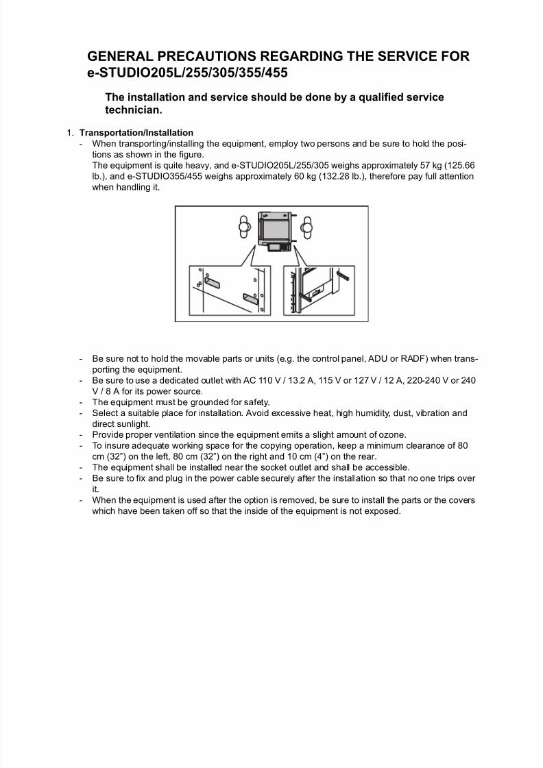
1. Transportation/Installation- When transporting/installing the equipment, employ two persons and be sure to hold the posi-
tions as shown in the figure.
The equipment is quite heavy, and e-STUDIO205L/255/305 weighs approximately 57 kg (125.66
lb.), and e-STUDIO355/455 weighs approximately 60 kg (132.28 lb.), therefore pay full attention
when handling it.
- Be sure not to hold the movable parts or units (e.g. the control panel, ADU or RADF) when trans-
porting the equipment.
- Be sure to use a dedicated outlet with AC 110 V / 13.2 A, 115 V or 127 V / 12 A, 220-240 V or 240
V / 8 A for its power source.
- The equipment must be grounded for safety.- Select a suitable place for installation. Avoid excessive heat, high humidity, dust, vibration and
direct sunlight.
- Provide proper ventilation since the equipment emits a slight amount of ozone.
- To insure adequate working space for the copying operation, keep a minimum clearance of 80
cm (32”) on the left, 80 cm (32”) on the right and 10 cm (4”) on the rear.
- The equipment shall be installed near the socket outlet and shall be accessible.
- Be sure to fix and plug in the power cable securely after the installation so that no one trips over
it.
- When the equipment is used after the option is removed, be sure to install the parts or the covers
which have been taken off so that the inside of the equipment is not exposed.

8/17/2019 Toshiba ES455 Service Manual
http://slidepdf.com/reader/full/toshiba-es455-service-manual 4/335
2) General Precautions at Service
- Be sure to turn the power OFF and unplug the power cable during service (except for the service
should be done with the power turned ON).
- Unplug the power cable and clean the area around the prongs of the plug and socket outlet once
a year or more. A fire may occur when dust lies on this area.
- When the parts are disassembled, reassembly is the reverse of disassembly unless otherwise
noted in this manual or other related documents. Be careful not to install small parts such as
screws, washers, pins, E-rings, star washers in the wrong places.- Basically, the equipment should not be operated with any parts removed or disassembled.
- The PC board must be stored in an anti-electrostatic bag and handled carefully using a wristband
since the ICs on it may be damaged due to static electricity.
- Avoid expose to laser beam during service. This equipment uses a laser diode. Be sure not to
expose your eyes to the laser beam. Do not insert reflecting parts or tools such as a screwdriver
on the laser beam path. Remove all reflecting metals such as watches, rings, etc. before starting
service.
- Be sure not to touch high-temperature sections such as the exposure lamp, fuser unit, damp
heater and areas around them.- Be sure not to touch high-voltage sections such as the chargers, transfer roller, developer, high-
voltage transformer, exposure lamp control inverter, inverter for the LCD backlight and power
supply unit. Especially, the board of these components should not be touched since the electric
charge may remain in the capacitors, etc. on them even after the power is turned OFF.
- Make sure that the equipment will not operate before touching potentially dangerous places (e.g.
rotating/operating sections such as gears, belts pulleys, fans and laser beam exit of the laser
optical unit).
- Be careful when removing the covers since there might be the parts with very sharp edges
underneath.
- When servicing the equipment with the power turned ON, be sure not to touch live sections and
rotating/operating sections. Avoid exposing your eyes to laser beam.
- Use designated jigs and tools.
- Use recommended measuring instruments or equivalents.
- Return the equipment to the original state and check the operation when the service is finished.
- Be very careful to treat the touch panel gently and never hit it. Breaking the surface could cause
malfunctions.
3) Important Service Parts for Safety
- The breaker, door switch, fuse, thermostat, thermofuse, thermistor, batteries, IC-RAMs including
lithium batteries, etc. are particularly important for safety. Be sure to handle/install them properly.
If these parts are short-circuited and their functions become ineffective, they may result in fatal
accidents such as burnout. Do not allow a short-circuit or do not use the parts not recommended
by Toshiba TEC Corporation.
4) Cautionary Labels- During servicing, be sure to check the rating plate and cautionary labels such as “Unplug the
power cable during service”, “CAUTION. HOT”, “CAUTION. HIGH VOLTAGE”, “CAUTION.
LASER BEAM”, etc. to see if there is any dirt on their surface and if they are properly stuck to the
equipment.
Caution: Before using the wristband, unplug the power cable of the equipment and
make sure that there are no charged objects which are not insulated in the
vicinity.

8/17/2019 Toshiba ES455 Service Manual
http://slidepdf.com/reader/full/toshiba-es455-service-manual 5/335
5) Disposal of the Equipment, Supplies, Packing Materials, Used Batteries and IC-RAMs includ-
ing lithium batteries
- Regarding the recovery and disposal of the equipment, supplies, packing materials, used batter-
ies and IC-RAMs including lithium batteries, follow the relevant local regulations or rules.
Caution:Dispose of used batteries and IC-RAMs including lithium batteries according to this manual.
Attention:Se débarrasser de batteries et IC-RAMs usés y compris les batteries en lithium selon ce manuel.Vorsicht:
Entsorgung der gebrauchten Batterien und IC-RAMs (inclusive der Lithium-Batterie) nach diesem Handbuch.

8/17/2019 Toshiba ES455 Service Manual
http://slidepdf.com/reader/full/toshiba-es455-service-manual 6/335

8/17/2019 Toshiba ES455 Service Manual
http://slidepdf.com/reader/full/toshiba-es455-service-manual 7/335
ALLEGEMEINE SICHERHEITSMASSNAHMEN IN BEZUGAUF DIE WARTUNG FÜR e-STUDIO205L/255/305/355/455
Die Installation und die Wartung sind von einem qualifizierten Service-Techniker durchzuführen.
1. Transport/Installation- Zum Transportieren/Installieren des Gerätes werden 2 Personen benötigt. Nur an den in der
Abbildung gezeigten Stellen tragen.
Das Gerät ist sehr schwer und wiegt etwa 57 kg (e-STUDIO205L/255/305) oder 60 kg (e-
STUDIO355/455); deshalb muss bei der Handhabung des Geräts besonders aufgepasst wer-
den.
- Beim Transportieren des Geräts nicht an den beweglichen Teilen oder Einheiten (z.B. das Bedie-
nungsfeld, die Duplexeinheit oder die automatische Dokumentenzuführung) halten.
- Eine spezielle Steckdose mit Stromversorgung von AC 110 V / 13.2 A, 115 V oder 127 V / 12 A,
220-240 V / 8 A als Stromquelle verwenden.
- Das Gerät ist aus Sicherheitsgründen zu erden.- Einen geeigneten Standort für die Installation wählen. Standorte mit zuviel Hitze, hoher Luft-
feuchtigkeit, Staub, Vibrieren und direkter Sonneneinstrahlung sind zu vermeiden.
- Für ausreichende Belüftung sorgen, da das Gerät etwas Ozon abgibt.
- Um einen optimalen Kopierbetrieb zu gewährleisten, muss ein Abstand von mindestens 80 cm
links, 80 cm rechts und 10 cm dahinter eingehalten werden.
- Das Gerät ist in der Nähe der Steckdose zu installieren; diese muss leicht zu erreichen sein.
- Nach der Installation muss das Netzkabel richtig hineingesteckt und befestigt werden, damit nie-
mand darüber stolpern kann.
- Falls der Auspackungsstandort und der Installationsstandort des Geräts verschieden sind, die
Bildqualitätsjustierung (automatische Gammajustierung) je nach der Temperatur und Luft-
feuchtigkeit des Installationsstandorts und der Papiersorte, die verwendet wird, durchführen.

8/17/2019 Toshiba ES455 Service Manual
http://slidepdf.com/reader/full/toshiba-es455-service-manual 8/335
2) Allgemeine Sicherheitsmassnahmen in bezug auf die Wartung
- Während der Wartung das Gerät ausschalten und das Netzkabel herausziehen (ausser Wartung,
die bei einem eingeschalteten Gerät, durchgeführt werden muss).
- Das Netzkabel herausziehen und den Bereich um die Steckerpole und die Steckdose die Umge-
bung in der Nähe von den Steckerzacken und der Steckdose wenigstens einmal im Jahr reini-
gen. Wenn Staub sich in dieser Gegend ansammelt, kann dies ein Feuer verursachen.
- Wenn die Teile auseinandergenommen werden, wenn nicht anders in diesem Handbuch usw
erklärt, ist das Zusammenbauen in umgekehrter Reihenfolge durchzuführen. Aufpassen, dasskleine Teile wie Schrauben, Dichtungsringe, Bolzen, E-Ringe, Stern-Dichtungsringe, Kabel-
bäume nicht an den verkehrten Stellen eingebaut werden.
- Grundsätzlich darf das Gerät mit enfernten oder auseinandergenommenen Teilen nicht in
Betrieb genommen werden.
- Das PC-Board muss in einer Anti-elektrostatischen Hülle gelagert werden. Nur Mit einer Man-
schette bei Betätigung eines Armbandes anfassen, sonst könnte es sein, dass die integrierten
Schaltkreise durch statische Elektrizität beschädigt werden.
- Setzen Sie sich während der Wartungsarbeiten nicht dem Laserstrahl aus. Dieses Gerät ist mit
einer Laserdiode ausgestattet. Es ist unbedingt zu vermeiden, direkt in den Laserstrahl zublicken. Keine reflektierenden Teile oder Werkzeuge, wie z. B. Schraubendreher, in den Pfad des
Laserstrahls halten. Vor den Wartungsarbeiten sämtliche reflektierenden Metallgegenstände, wie
Uhren, Ringe usw., entfernen.
- Auf keinen Fall Hochtemperaturbereiche, wie die Belichtungslampe, die Fixiereinheit, die
Heizquelle und die umliegenden Bereiche, berühren.
- Auf keinen Fall Hochspannungsbereiche, wie die Ladeeinheiten, das Transferband, die zweite
Transferwalze, die Entwicklereinheit, den Hochspannungstransformator, den Steuerumrichter für
die Belichtungslampe, den Umrichter für die LCD-Hintergrundbeleuchtung und das Netzgerät,
berühren. Insbesondere sollten die Platinen dieser Komponenten nicht berührt werden, da die
Kondensatoren usw. auch nach dem Ausschalten des Geräts noch elektrisch geladen sein kön-
nen.
- Vor dem Berühren potenziell gefährlicher Bereiche (z. B. drehbare oder betriebsrelevante Bere-
iche, wie Zahnräder, Riemen, Riemenscheiben, Lüfter und die Laseraustrittsöffnung der optis-chen Lasereinheit) sicherstellen, dass das Gerät sich nicht bedienen lässt.
- Beim Entfernen von Abdeckungen vorsichtig vorgehen, da sich darunter scharfkantige Kompo-
nenten befinden können.
- Bei Wartungsarbeiten am eingeschalteten Gerät dürfen keine unter Strom stehenden, drehbaren
oder betriebsrelevanten Bereiche berührt werden. Nicht direkt in den Laserstrahl blicken.
- Ausschließlich vorgesehene Werkzeuge und Hilfsmittel verwenden.
- Empfohlene oder gleichwertige Messgeräte verwenden.
- Nach Abschluss der Wartungsarbeiten das Gerät in den ursprünglichen Zustand zurück
versetzen und den einwandfreien Betrieb überprüfen.
- Das berührungsempfindliche Bedienungsfeld stets vorsichtig handhaben und keinen Stößen
aussetzen. Wenn die Oberfläche beschädigt wird, kann dies zu Funktionsstörungen führen.
3) Sicherheitsrelevante Wartungsteile
- Der Leistungsschutzschalter, der Türschalter, die Sicherung, der Thermostat, die Ther-
mosicherung, der Thermistor, die IC-RAMs einschließlich der Lithiumakkus usw. sind besonders
sicherheitsrelevant. Sie müssen unbedingt korrekt gehandhabt und installiert werden. Wenn
diese Teile kurzgeschlossen und funktionsunfähig werden, kann dies zu schwerwiegenden
Schäden, wie einem Abbrand, führen. Kurzschlüsse sind zu vermeiden, und es sind auss-
chließlich Teile zu verwenden, die von der Toshiba TEC Corporation empfohlen sind.
Vorsicht: Vor Benutzung der Manschette der Betätigung des Armbandes, das Netzkabeldes Gerätes herausziehen und prüfen, dass es in der Nähe keine geladenenGegenstände, die nicht isoliert sind, gibt.

8/17/2019 Toshiba ES455 Service Manual
http://slidepdf.com/reader/full/toshiba-es455-service-manual 9/335
4) Warnetiketten
- Im Rahmen der Wartung unbedingt das Leistungsschild und die Etiketten mit Warnhinweisen
überprüfen [z. B. „Unplug the power cable during service“ („Netzkabel vor Beginn der Wartung-
sarbeiten abziehen“), „CAUTION. HOT“ („VORSICHT, HEISS“), „CAUTION. HIGH VOLTAGE“
(„VORSICHT, HOCHSPANNUNG“), „CAUTION. LASER BEAM“ („VORSICHT, LASER“) usw.],
um sicherzustellen, dass sie nicht verschmutzt sind und korrekt am Gerät angebracht sind.
5) Entsorgung des Geräts, der Verbrauchs- und Verpackungsmaterialien, alter Akkus und IC-RAMs- In Bezug auf die Entsorgung und Wiederverwertung des Geräts, der Verbrauchs- und Verpack-
ungsmaterialien, alter Akkus und IC-RAMs, einschließlich Lithiumakkus, sind die einschlägigen
nationalen oder regionalen Vorschriften zu befolgen.
Caution:Dispose of used batteries and IC-RAMs including lithium batteries according to this manual.
Attention:Se débarrasser de batteries et IC-RAMs usés y compris les batteries en lithium selon ce manuel.
Vorsicht:Entsorgung der gebrauchten Batterien und IC-RAMs (inclusive der Lithium-Batterie) nach diesem Handbuch.
8/17/2019 Toshiba ES455 Service Manual
http://slidepdf.com/reader/full/toshiba-es455-service-manual 10/335
• Laseremissionseinheit
Diese Einheit besteht aus der Laserdiode, dem Fokussierungsobjektiv, der Blende und dem Zylin-
derobjektiv.
- Laserdiode
Diese Laserdiode zeichnet sich durch eine geringe Regeldifferenz, eine kleine Laservariation und
einen niedrigen Schwellenstrom aus.Die Blende der Laseremissionseinheit ist unter dem Fokussierobjektiv angeordnet, um die Form der
Laserstrahlen in der primären und sekundären Scanrichtung festzulegen.
Die Laserdiode gibt Laserstrahlen als Reaktion auf die Signale der Laseremissionssteuerung (ein/
aus) von der Lasertreiber-PC-Platine (LDR) aus. Die durch das Fokussierobjektiv geführten Laser-
strahlen werden auf die Trommeloberfläche fokussiert.
- Vorsichtsmaßnahmen im Zusammenhang mit Lasern
Dieses Gerät enthält eine Laserdiode, die einen unsichtbaren Laserstrahl emittiert.
Da man diesen Laserstrahl nicht sehen kann, ist bei der Handhabung der Komponenten der optis-
chen Lasereinheit, bei der Durchführung von Arbeiten und bei der Justierung des Laserstrahls
äußerste Vorsicht geboten. Arbeiten dürfen niemals anhand anderer als den vorgeschriebenen
Anleitungen durchgeführt werden; andernfalls kann es zu einer Schädigung Exposition durch Laser-
strahlung kommen.Die Lasereinheit ist vollständig mit einer Schutzabdeckung versiegelt. Solange ausschließlich die
Arbeitsschritte der vorgeschriebenen Anleitungen durchgeführt werden, tritt der Laserstrahl nicht
aus, und es besteht keine Gefahr, der Laserstrahlung ausgesetzt zu werden.
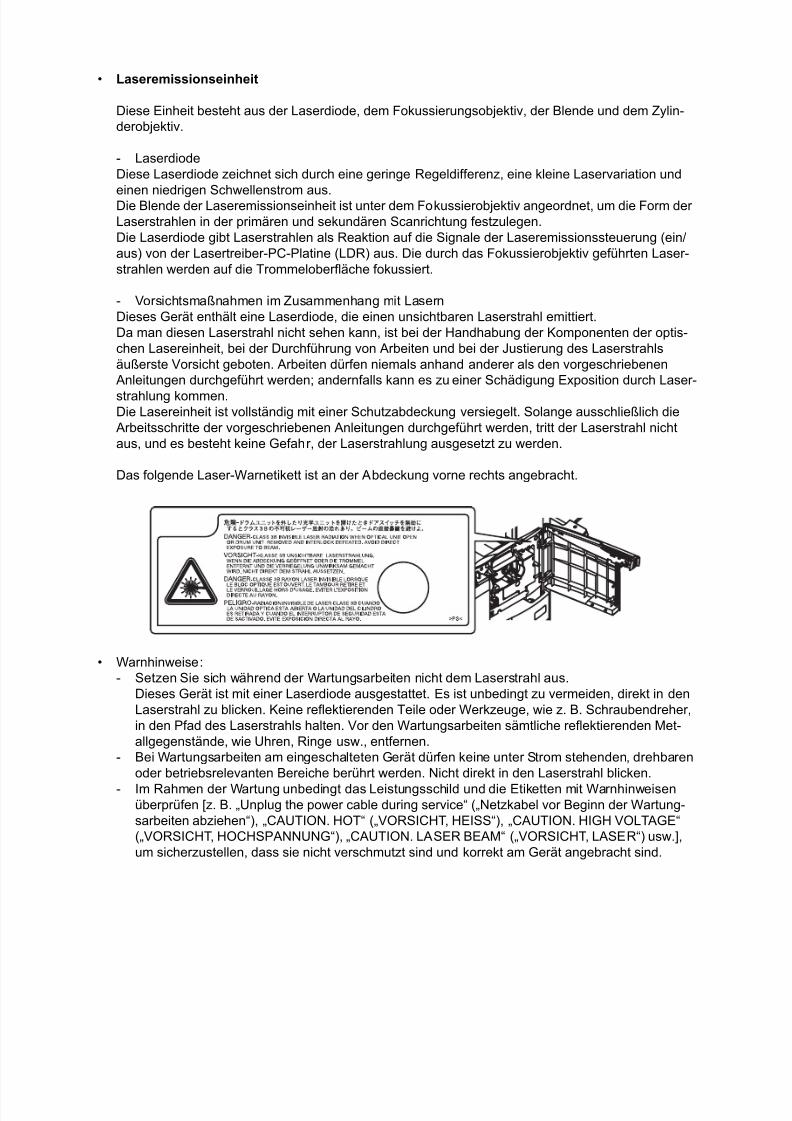
Das folgende Laser-Warnetikett ist an der Abdeckung vorne rechts angebracht.
• Warnhinweise:
- Setzen Sie sich während der Wartungsarbeiten nicht dem Laserstrahl aus.
Dieses Gerät ist mit einer Laserdiode ausgestattet. Es ist unbedingt zu vermeiden, direkt in den
Laserstrahl zu blicken. Keine reflektierenden Teile oder Werkzeuge, wie z. B. Schraubendreher,
in den Pfad des Laserstrahls halten. Vor den Wartungsarbeiten sämtliche reflektierenden Met-
allgegenstände, wie Uhren, Ringe usw., entfernen.
- Bei Wartungsarbeiten am eingeschalteten Gerät dürfen keine unter Strom stehenden, drehbaren
oder betriebsrelevanten Bereiche berührt werden. Nicht direkt in den Laserstrahl blicken.
- Im Rahmen der Wartung unbedingt das Leistungsschild und die Etiketten mit Warnhinweisenüberprüfen [z. B. „Unplug the power cable during service“ („Netzkabel vor Beginn der Wartung-
sarbeiten abziehen“), „CAUTION. HOT“ („VORSICHT, HEISS“), „CAUTION. HIGH VOLTAGE“
(„VORSICHT, HOCHSPANNUNG“), „CAUTION. LASER BEAM“ („VORSICHT, LASER“) usw.],
um sicherzustellen, dass sie nicht verschmutzt sind und korrekt am Gerät angebracht sind.

8/17/2019 Toshiba ES455 Service Manual
http://slidepdf.com/reader/full/toshiba-es455-service-manual 11/335
© 2009 TOSHIBA TEC CORPORATION All rights reserved e-STUDIO205L/255/305/355/455CONTENTS
1
CONTENTS
1. SPECIFICATIONS / ACCESSORIES / OPTIONS / SUPPLIES ...................................1-11.1 Specifications ....................................................................................................................1-1
1.1.1 General .............................................................................................................. 1-1
1.1.2 Copy .................................................................................................................. 1-4
1.2 Accessories.......................................................................................................................1-8
1.3 Options.............................................................................................................................. 1-9
1.4 Supplies ..........................................................................................................................1-101.5 System List......................................................................................................................1-11
1.5.1 e-STUDIO205L/255/305 ..................................................................................1-11
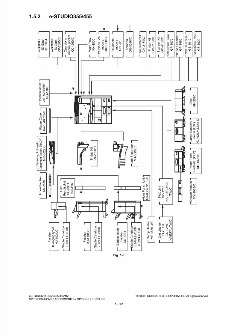
1.5.2 e-STUDIO355/455 ...........................................................................................1-12
2. OUTLINE OF THE MACHINE....................................................................................... 2-12.1 Sectional View................................................................................................................... 2-1
2.2 Electric Parts Layout ......................................................................................................... 2-4
2.3 Symbols and Functions of Various Components ............................................................2-13
2.4 System block diagram.....................................................................................................2-18
2.5 Installation and Replacement of Covers .........................................................................2-20
2.5.1 Front cover....................................................................................................... 2-20
2.5.2 Front upper cover ............................................................................................ 2-20
2.5.3 Front lower cover .............................................................................................2-212.5.4 Left upper cover............................................................................................... 2-21
2.5.5 Right upper cover ............................................................................................ 2-22
2.5.6 Rear cover .......................................................................................................2-22
2.5.7 Upper rear cover..............................................................................................2-23
2.5.8 Left rear cover..................................................................................................2-23
2.5.9 Inner tray.......................................................................................................... 2-23
2.5.10 Left cover.........................................................................................................2-24
2.5.11 Tray back cover ...............................................................................................2-24
2.5.12 Connecting port cover......................................................................................2-24
2.5.13 Right rear cover ...............................................................................................2-25
2.5.14 Right front cover ..............................................................................................2-25
2.5.15 Left front cover.................................................................................................2-262.6 Installation and Replacement of PC boards.................................................................... 2-27
2.6.1 Image processing PC board (IMG board)........................................................2-27
2.6.2 Hard disk (HDD) ..............................................................................................2-27
2.6.3 System control PC board (SYS board) ............................................................2-28
2.6.4 Logic PC board (LGC board) ...........................................................................2-28
2.6.5 MOT board (e-STUDIO205L/255/305) ............................................................ 2-29
2.6.6 MOT2 board (e-STUDIO355/455) ...................................................................2-29
2.6.7 Switching regulator .......................................................................................... 2-30
2.6.8 High-voltage transformer ................................................................................. 2-30
2.6.9 SRAM board .................................................................................................... 2-32
2.7 Installation and Replacement of Options ........................................................................2-33
2.7.1 MR-3021/MR3022 (Reversing Automatic Document Feeder (RADF)) ............2-33
2.7.2 KD-1025 (Paper Feed Pedestal (PFP)) ........................................................... 2-35
2.7.3 KD-1026 (Large Capacity Feeder (LCF)) ........................................................2-37
2.7.4 MJ-1031 (Hanging finisher) .............................................................................2-40
2.7.5 MJ-1101 (Finisher)........................................................................................... 2-41
2.7.6 MJ-1024 (Saddle stitch finisher) .....................................................................2-42
2.7.7 MJ-1025 (Saddle stitch finisher) ......................................................................2-44
2.7.8 KN-2520 (Bridge unit) ...................................................................................... 2-45
2.7.9 MJ-5004 (Job separator) (e-STUDIO205L/255/305) .......................................2-47
2.7.10 MJ-5005 (Offset tray) (e-STUDIO205L/255/305).............................................2-49
2.7.11 MJ-5006 (Job separator) (e-STUDIO355/455) ................................................ 2-51
2.8 Damp Heater Kit (MF-4550U/E) Installation Procedure ..................................................2-53
8/17/2019 Toshiba ES455 Service Manual
http://slidepdf.com/reader/full/toshiba-es455-service-manual 12/335
e-STUDIO205L/255/305/355/455 © 2009 TOSHIBA TEC CORPORATION All rights reservedCONTENTS
2
2.8.1 Preparation ...................................................................................................... 2-53
2.8.2 Procedure ........................................................................................................2-53
3. COPY PROCESS .......................................................................................................... 3-13.1 General Description of Copying Process ..........................................................................3-1
3.2 Details of Copying Process ...............................................................................................3-2
3.3 Comparison with e-STUDIO200L/202L/203L/230/230L/232/233/232S/280/280S/282/
283/282S/283S ............................................................................................................... 3-12
4. GENERAL OPERATION...............................................................................................4-1
4.1 Overview of Operation ......................................................................................................4-14.2 Description of Operation ...................................................................................................4-2
4.2.1 Warming-up .......................................................................................................4-2
4.2.2 Ready state (ready for copying).........................................................................4-2
4.2.3 Drawer feed copying (Upper drawer paper feeding).......................................... 4-3
4.2.4 Bypass feed copying..........................................................................................4-5
4.2.5 Interruption copying ...........................................................................................4-5
4.3 Detection of Abnormality................................................................................................... 4-6
4.3.1 Types of abnormality .........................................................................................4-6
4.3.2 Description of abnormality .................................................................................4-6
5. CONTROL PANEL........................................................................................................5-15.1 General Description .......................................................................................................... 5-1
5.2 Items Shown on the Display Panel ................................................................................... 5-25.2.1 Display ............................................................................................................... 5-2
5.2.2 Message ............................................................................................................5-3
5.3 Relation between the Equipment State and Operator’s Operation ................................... 5-7
5.4 Description of Operation .................................................................................................5-10
5.4.1 Dot matrix LCD circuit ...................................................................................... 5-10
5.4.2 LED display circuit ...........................................................................................5-11
5.5 Disassembly and Replacement.......................................................................................5-12
5.5.1 Stopper ............................................................................................................5-12
5.5.2 Control panel unit............................................................................................. 5-12
5.5.3 Panel inverter board (P-INV) ...........................................................................5-14
5.5.4 Display board (DSP) ........................................................................................5-14
5.5.5 KEY board (KEY)............................................................................................. 5-165.5.6 Touch panel (TCP) ..........................................................................................5-17
5.5.7 Control panel cover..........................................................................................5-17
6. SCANNER..................................................................................................................... 6-16.1 General Description .......................................................................................................... 6-1
6.2 Construction......................................................................................................................6-2
6.3 Functions........................................................................................................................... 6-3
6.4 Description of Operation ...................................................................................................6-6
6.4.1 Scanning operation............................................................................................6-6
6.5 Electric Circuit Description ................................................................................................6-7
6.5.1 Scan motor control circuit ..................................................................................6-7
6.5.2 Exposure lamp control circuit.............................................................................6-8
6.5.3 General description of CCD control.................................................................6-116.5.4 Automatic original size detection circuit........................................................... 6-12
6.6 Disassembly and Replacement.......................................................................................6-16
6.6.1 Original glass ...................................................................................................6-16
6.6.2 Lens cover .......................................................................................................6-16
6.6.3 Automatic original detection sensor (S1-5)...................................................... 6-17
6.6.4 Exposure lamp (EXP) ......................................................................................6-18
6.6.5 Lens unit .......................................................................................................... 6-20
6.6.6 Scan motor (M1) .............................................................................................. 6-23
6.6.7 Carriage-1........................................................................................................6-24
6.6.8 Lamp inverter board (INV) ............................................................................... 6-27
6.6.9 Installing the lamp harness ..............................................................................6-28

8/17/2019 Toshiba ES455 Service Manual
http://slidepdf.com/reader/full/toshiba-es455-service-manual 13/335
© 2009 TOSHIBA TEC CORPORATION All rights reserved e-STUDIO205L/255/305/355/455CONTENTS
3
6.6.10 Carriage wire / carriage-2 ................................................................................ 6-30
6.6.11 Platen sensor (S6) / Carriage home position sensor (S7) ............................... 6-31
6.6.12 SLG board (SLG).............................................................................................6-31
7. LASER OPTICAL UNIT ................................................................................................ 7-17.1 General Description .......................................................................................................... 7-1
7.2 Structure............................................................................................................................ 7-2
7.3 Laser Diode Control Circuit ............................................................................................... 7-5
7.4 Polygonal Motor Control Circuit ........................................................................................ 7-6
7.5 Disassembly and Replacement......................................................................................... 7-7
7.5.1 Laser optical unit................................................................................................7-7
8. PAPER FEEDING SYSTEM..........................................................................................8-18.1 General Descriptions.........................................................................................................8-1
8.2 Composition ...................................................................................................................... 8-3
8.3 Functions........................................................................................................................... 8-4
8.4 Operation ..........................................................................................................................8-6
8.4.1 Bypass feeding mechanism............................................................................... 8-6
8.4.2 Operation of drawer pickup roller....................................................................... 8-7
8.4.3 Separation of paper ...........................................................................................8-8
8.4.4 Operation of clutch.............................................................................................8-9
8.4.5 General operation............................................................................................8-10
8.5 Drive Circuit of Tray-up Motor.........................................................................................8-128.6 Disassembly and Replacement.......................................................................................8-13
8.6.1 Drawer ............................................................................................................. 8-13
8.6.2 Drawer feeding unit.......................................................................................... 8-13
8.6.3 Tray-up sensor (S16/S19) ...............................................................................8-14
8.6.4 Empty sensor (S17/S20)..................................................................................8-14
8.6.5 Paper stock sensor (S15/S18)......................................................................... 8-15
8.6.6 Separation roller ............................................................................................. 8-15
8.6.7 Feed roller .......................................................................................................8-16
8.6.8 Pickup roller .................................................................................................... 8-16
8.6.9 Drawer feed clutch (CLT4/CLT5)..................................................................... 8-17
8.6.10 Bypass tray......................................................................................................8-18
8.6.11 Paper width detection PC board (SFB)............................................................ 8-19
8.6.12 Bypass feed unit .............................................................................................. 8-208.6.13 Bypass separation pad ...................................................................................8-21
8.6.14 Bypass feed roller /Bypass feed clutch (CLT3)................................................8-21
8.6.15 Bypass paper sensor (S12) .............................................................................8-22
8.6.16 Registration guide............................................................................................8-23
8.6.17 Registration sensor (S22)................................................................................ 8-23
8.6.18 1st transport sensor (S21))..............................................................................8-24
8.6.19 Feed cover.......................................................................................................8-24
8.6.20 Transport roller ................................................................................................8-25
8.6.21 2nd transport sensor (S14)..............................................................................8-26
8.6.22 Feed cover opening/closing detection sensor (S13)........................................ 8-26
8.6.23 Flywheel........................................................................................................... 8-26
8.6.24 Registration roller clutch (CLT2)...................................................................... 8-278.6.25 Upper tray-up motor (M11) ..............................................................................8-27
8.6.26 Upper drawer detection switch (SW7) ............................................................. 8-28
8.6.27 Hi-speed clutch (CLT6) / Low-speed clutch(CLT7)..........................................8-29
8.6.28 Lower drawer detection switch (SW8) ............................................................. 8-30
8.6.29 Lower tray-up motor (M15) ..............................................................................8-31
8.6.30 Registration roller (rubber)...............................................................................8-32
8.6.31 Registration roller (metal) ................................................................................ 8-33
9. DRIVE SYSTEM............................................................................................................9-19.1 General Description .......................................................................................................... 9-1
9.2 Functions........................................................................................................................... 9-2
9.3 Main Motor ........................................................................................................................ 9-3
8/17/2019 Toshiba ES455 Service Manual
http://slidepdf.com/reader/full/toshiba-es455-service-manual 14/335
e-STUDIO205L/255/305/355/455 © 2009 TOSHIBA TEC CORPORATION All rights reservedCONTENTS
4
9.3.1 Main motor drive ................................................................................................9-3
9.4 Disassembly and Replacement......................................................................................... 9-5
9.4.1 Main motor (M8) ................................................................................................ 9-5
9.4.2 Toner motor (M4)...............................................................................................9-5
9.4.3 Main motor drive unit .........................................................................................9-6
10. DRUM RELATED SECTION....................................................................................... 10-110.1 Configuration................................................................................................................... 10-1
10.2 Composition ....................................................................................................................10-2
10.3 Functions.........................................................................................................................10-3
10.4 High-Voltage Transformer Output Control Circuit ...........................................................10-5
10.4.1 General description..........................................................................................10-5
10.4.2 Description of operation...................................................................................10-6
10.5 Drum Temperature Detection Circuit ..............................................................................10-7
10.5.1 General description..........................................................................................10-7
10.5.2 Construction.....................................................................................................10-7
10.6 Temperature/Humidity Detection Circuit .........................................................................10-8
10.6.1 General description..........................................................................................10-8
10.6.2 Construction .................................................................................................... 10-8
10.7 Disassembly and Replacement.......................................................................................10-9
10.7.1 Process unit ..................................................................................................... 10-9
10.7.2 Drum cleaner unit ............................................................................................10-9
10.7.3 Discharge LED............................................................................................... 10-1110.7.4 Main charger..................................................................................................10-12
10.7.5 Main charger grid ..........................................................................................10-13
10.7.6 Main charger cleaner .....................................................................................10-13
10.7.7 Needle electrode .......................................................................................... 10-13
10.7.8 Drum .............................................................................................................10-14
10.7.9 Drum cleaning blade .....................................................................................10-15
10.7.10 Drum separation finger ................................................................................ 10-15
10.7.11 Recovery blade ............................................................................................. 10-16
10.7.12 Ozone filter ...................................................................................................10-16
10.7.13 TRU fan (M9).................................................................................................10-17
10.7.14 Transfer roller unit..........................................................................................10-18
10.7.15 Transfer roller ...............................................................................................10-1910.7.16 Separation needle.......................................................................................... 10-19
10.7.17 Transfer unit................................................................................................... 10-20
10.7.18 Temperature/humidity sensor (S25) ..............................................................10-20
11. DEVELOPMENT SYSTEM.......................................................................................... 11-111.1 Configuration................................................................................................................... 11-1
11.2 Construction ....................................................................................................................11-2
11.3 Functions.........................................................................................................................11-3
11.3.1 General description..........................................................................................11-3
11.3.2 Recovered process unit mechanism................................................................11-4
11.3.3 Recovered toner supply mechanism ............................................................... 11-5
11.4 Electric Circuit Description .............................................................................................. 11-6
11.4.1 Functions of the toner cartridge PC board (CTRG) ......................................... 11-611.4.2 Drive circuit of toner motor............................................................................... 11-8
11.5 Auto-Toner Circuit ........................................................................................................... 11-9
11.5.1 General description..........................................................................................11-9
11.5.2 Function of auto-toner sensor........................................................................11-10
11.6 Disassembly and Replacement..................................................................................... 11-12
11.6.1 Process unit ...................................................................................................11-12
11.6.2 Developer unit................................................................................................11-13
11.6.3 Removing developer material ....................................................................... 11-13
11.6.4 Filling developer unit with developer material ................................................11-14
11.6.5 EPU memory board (EPU) ............................................................................11-15
11.6.6 Auto-toner sensor (S8) .................................................................................. 11-15
8/17/2019 Toshiba ES455 Service Manual
http://slidepdf.com/reader/full/toshiba-es455-service-manual 15/335
© 2009 TOSHIBA TEC CORPORATION All rights reserved e-STUDIO205L/255/305/355/455CONTENTS
5
11.6.7 Drum thermistor (THMS4) .............................................................................11-16
11.6.8 Guide roller / Developer sleeve ..................................................................... 11-16
11.6.9 Mixer..............................................................................................................11-21
11.6.10 Replacement of oil seal ................................................................................. 11-24
12. FUSER UNIT ............................................................................................................... 12-112.1 General Description ........................................................................................................12-1
12.2 Functions.........................................................................................................................12-3
12.3 Operation ........................................................................................................................ 12-4
12.4 Heater Control Circuit......................................................................................................12-5
12.4.1 Configuration ...................................................................................................12-5
12.4.2 Temperature detection section ........................................................................12-6
12.5 Fuser unit fuse status determining circuit......................................................................12-11
12.6 Disassembly and Replacement..................................................................................... 12-13
12.6.1 Fuser unit.......................................................................................................12-13
12.6.2 Fuser roller unit / Pressure roller unit............................................................. 12-13
12.6.3 Separation finger ...........................................................................................12-14
12.6.4 Fuser roller.....................................................................................................12-14
12.6.5 Heater lamp ...................................................................................................12-15
12.6.6 Thermistor......................................................................................................12-16
12.6.7 Thermostat.....................................................................................................12-17
12.6.8 Pressure roller ...............................................................................................12-19
12.6.9 Exit sensor..................................................................................................... 12-2112.6.10 Installation of the fuser unit fuse (service part) ..............................................12-22
13. PAPER EXIT SECTION/REVERSE SECTION ...........................................................13-113.1 General Description ........................................................................................................13-1
13.2 Functions.........................................................................................................................13-2
13.3 Control Circuit of Exit Motor / Reverse Motor / Offset Gate Motor .................................. 13-3
13.4 Exit Motor / Reverse Motor / Offset Gate Motor Drive ....................................................13-5
13.5 Disassembly and Replacement.......................................................................................13-7
13.5.1 Reverse unit (only installed for e-STUDIO355/455) ........................................13-7
13.5.2 Paper exit unit.................................................................................................. 13-8
13.5.3 Exit motor......................................................................................................... 13-9
13.5.4 Offset gate home position sensor..................................................................13-10
13.5.5 Exit roller........................................................................................................13-1013.5.6 Reverse motor (only installed for e-STUDIO355/455)...................................13-11
13.5.7 Reverse gate solenoid (only installed for e-STUDIO355/455).......................13-12
13.5.8 Reverse sensor (only installed for e-STUDIO355/455) .................................13-13
13.5.9 Offset gate motor (only installed for e-STUDIO355/455)...............................13-14
13.5.10 Reverse roller (only installed for e-STUDIO355/455) ....................................13-14
13.5.11 Upper transport roller (only installed for e-STUDIO355/455) ........................13-15
14. AUTOMATIC DUPLEXING UNIT (ADU)..................................................................... 14-114.1 General Description ........................................................................................................14-1
14.2 Functions.........................................................................................................................14-2
14.3 Description of Operations................................................................................................14-3
14.4 Drive of ADU ...................................................................................................................14-8
14.5 Disassembly and Replacement.......................................................................................14-9
14.5.1 Automatic Duplexing Unit (ADU) .....................................................................14-9
14.5.2 ADU entrance sensor ....................................................................................14-10
14.5.3 ADU exit sensor.............................................................................................14-11
14.5.4 ADU motor..................................................................................................... 14-12
14.5.5 ADU opening / closing switch ........................................................................14-13
14.5.6 ADU clutch..................................................................................................... 14-14
14.5.7 ADU lower transport roller ............................................................................. 14-16
14.5.8 ADU upper transport roller............................................................................. 14-16
15. POWER SUPPLY UNIT .............................................................................................. 15-115.1 Construction ....................................................................................................................15-1
8/17/2019 Toshiba ES455 Service Manual
http://slidepdf.com/reader/full/toshiba-es455-service-manual 16/335
e-STUDIO205L/255/305/355/455 © 2009 TOSHIBA TEC CORPORATION All rights reservedCONTENTS
6
15.2 Operation of DC Output Circuits .....................................................................................15-2
15.3 Output Channel ...............................................................................................................15-4
15.4 Fuse ................................................................................................................................15-6
15.5 Configuration of Power Supply Unit ................................................................................ 15-7
15.6 AC Wire Harness ............................................................................................................15-8
16. PC BOARDS ............................................................................................................... 16-1

8/17/2019 Toshiba ES455 Service Manual
http://slidepdf.com/reader/full/toshiba-es455-service-manual 17/335
© 2009 TOSHIBA TEC CORPORATION All rights reserved e-STUDIO205L/255/305/355/455SPECIFICATIONS / ACCESSORIES / OPTIONS / SUPPLIES
1 - 1
1. SPECIFICATIONS / ACCESSORIES / OPTIONS / SUPPLIES
1.1 Specifications
1.1.1 General
Type......................................... Desktop type (console type: when paper feed pedestal (PFP) and large
capacity feeder (LCF) are installed)
Original glass........................... Fixed type (the left rear corner used as guide to place originals)
Copy process .......................... Indirect electrophotographic process (dry)
Fixing method.......................... External heating STF fusing system
Photosensor type ....................OPC
Original scanning sensor......... Linear CCD sensor
Scanning light source..............Xenon lamp
Reproduction ratio ................... Actual ratio: 100±0.5%
Zooming: 25 to 400% in increments of 1%
(25 to 200% when using RADF)
Resolution ............................... Scanning: 600 dpi x 600 dpiPrinting: Equivalent to 2400 dpi x 600 dpi
Gradation................................. 256 steps
Paper feeding.......................... 2 drawers + Bypass feeding + LCF (optional)
2 drawers + Bypass feeding + 2 PFP (optional)
Paper supply ...........................Standard drawers:
Stack height 60.5 mm, equivalent to 550 sheets; 80 g/m2 (22 lb.
Bond)): Depends on destinations or versions.
Bypass feeding:Stack height 11 mm: equivalent to 100 sheets; 80 g/m2 (22 lb.
Bond)
PFP:(Option):
Two drawer: stack height 60.5 mm, 550 sheets; 80 g/m2 (22 lb.
Bond)
LCF:(Option)
Stack height 110 mm x 2: equivalent to 1000 sheets; 80 g/m2 (22
lb. Bond)
Values in [[ ]] are for e-STUDIO205L, values in {{ }} are for e-STUDIO305, values in [ ] are for e-
STUDIO355, values in { } are for e-STUDIO455 and values in < > are for e-STUDIO355/455 in case
that the specification is different among e-STUDIO205L, e-STUDIO255, e-STUDIO305, e-STUDIO355 and e-STUDIO455.

8/17/2019 Toshiba ES455 Service Manual
http://slidepdf.com/reader/full/toshiba-es455-service-manual 18/335
e-STUDIO205L/255/305/355/455 © 2009 TOSHIBA TEC CORPORATION All rights reservedSPECIFICATIONS / ACCESSORIES / OPTIONS / SUPPLIES
1 - 2
paper
Automatic duplexing unit ......... Stackless, Switchback type
e-STUDIO205L/255/305: No exclusive switchback mechanism
e-STUDIO355/455: Uses an exclusive switchback mechanism
Acceptable paper size
A3, A4, A4-R, A5-R, B4, B5, B5-R, FOLIO, 8K, 16K, 16K-R, LD,
LG, LT, LT-R, ST-R, COMPUTER, 13"LG, 8.5" x 8.5"
Acceptable paper weight
64 g/m2 to 105 g/m2 (17 lb. Bond to 28 lb. Cover)
Offset mechanism ................... e-STUDIO205L/255/305: No exclusive offset mechanism
e-STUDIO355/455: Uses an exclusive offset mechanism
Offsetting mechanism with movable exit roller
(Shift amount: 30 mm, Stack height: 40 mm (250 sheets))
Interface ..................................Standard:
USB 2.0 (High Speed),
Ethernet (10BASE-T/100BASE-TX)
Optional:Wireless LAN (IEEE 802.11b/g),
Bluetooth (HCRP and BIP)
Toner supply............................ Automatic toner density detection/supply
Toner cartridge replacing method (There is a recovered toner supply
mechanism.)
Toner density control ............... Automatic density mode and manual density mode selectable in 11
steps
Memory (RAM)........................ Main memory: 1GB(Incl. page memory)
Paper size Drawers A3, A4, A4-R, A5-R, B4, B5, B5-R, FOLIO, 8K, 16K, 16K-R,LD, LG, LT, LT-R, ST-R, COMPUTER, 13"LG, 8.5"x8.5"(Non-standard sizes are not available)
Bypass feeding A3, A4, A4-R, A5-R, B4, B5, B5-R, FOLIO, 8K, 16K, 16K-R,LD, LG, LT, LT-R, ST-R, COMPUTER, 13"LG, 8.5"x8.5"
LCF (optional) A4, LT(Non-standard sizes are not available)
Paper type Drawers/LCF (optional) Plain paper (Tracing paper, OHP films, sticker labels, envelopes andpunched paper are not available)
Bypass feeding Plain paper, Tracing paper, OHP film, Sticker labels, Tab paper
Paper weight Drawers/LCF (optional) 64 g/m2 to 105 g/m2 (17 lb. Bond to 28 lb. Cover)
Bypass feeding 52g/m2 to 209 g/m2 (14 lb. Bond to 110 lb. Cover)
Plain paper: 64g/m2 to 80 g/m2 (17 lb. Bond to 21 lb. Cover)
Thin paper: 52g/m2 to 63 g/m2 (14 lb. Bond to 17 lb. Cover)
Thick 1: 81g/m2 to 105 g/m2 (21.5 lb. Bond to 28 lb. Cover)
Thick 2: 106g/m2 to 163 g/m2 (28 lb. Bond to 43 lb. Cover)
Thick 3: 164g/m2 to 209 g/m2 (43.5 lb. Bond to 55.5 lb. Cover)
64g/m2 to 209 g/m2 (17 lb. Bond to 110 lb. Cover)
ADU 64 g/m2 to 105 g/m2 (17 lb. Bond to 28 lb. Cover)
8/17/2019 Toshiba ES455 Service Manual
http://slidepdf.com/reader/full/toshiba-es455-service-manual 19/335
© 2009 TOSHIBA TEC CORPORATION All rights reserved e-STUDIO205L/255/305/355/455SPECIFICATIONS / ACCESSORIES / OPTIONS / SUPPLIES
1 - 3
HDD......................................... 60GB
Account Codes ........................ 10,000 codes
Department Codes ..................1,000 codes
Warming-up time ..................... Approx. 20 sec. (temperature: 20°C)
Power requirements ................ AC 110 V / 13.2 A, 115 V or 127 V / 12 A
220-240 V or 240 V / 8 A (50/60 Hz)* The acceptable value of each voltage is ±10%.
Power consumption................. 1.5 kW or less (115 V series, 200 V series)
* The electric power is supplied to the RADF, (ADU), Finisher, Job Separator, Offset Tray, PFP and
LCF through the equipment.
Total counter............................ Electronical counter
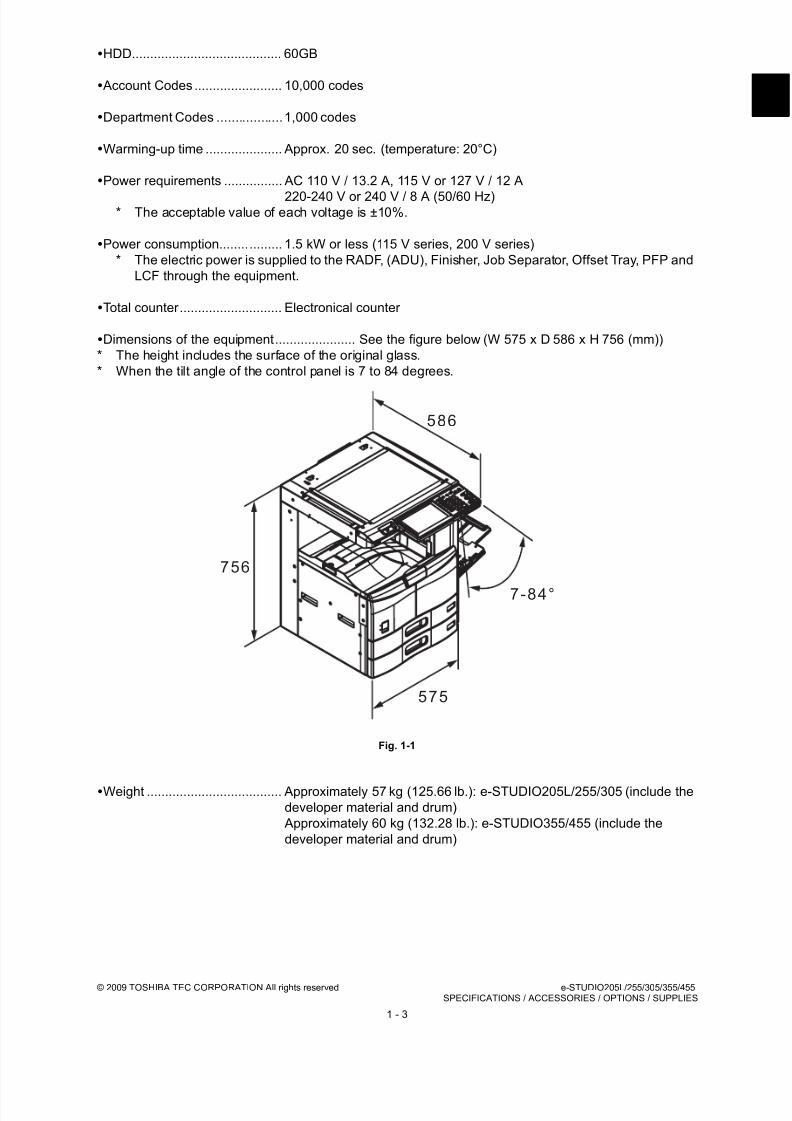
Dimensions of the equipment...................... See the figure below (W 575 x D 586 x H 756 (mm))
* The height includes the surface of the original glass.
* When the tilt angle of the control panel is 7 to 84 degrees.
Fig. 1-1
Weight ..................................... Approximately 57 kg (125.66 lb.): e-STUDIO205L/255/305 (include the
developer material and drum)
Approximately 60 kg (132.28 lb.): e-STUDIO355/455 (include the
developer material and drum)
586
756
575
7-84°
8/17/2019 Toshiba ES455 Service Manual
http://slidepdf.com/reader/full/toshiba-es455-service-manual 20/335
e-STUDIO205L/255/305/355/455 © 2009 TOSHIBA TEC CORPORATION All rights reservedSPECIFICATIONS / ACCESSORIES / OPTIONS / SUPPLIES
1 - 4
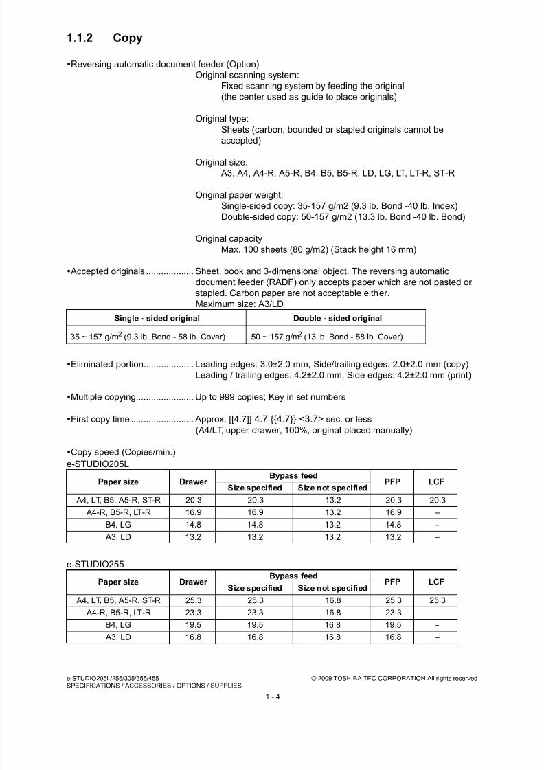
1.1.2 Copy
Reversing automatic document feeder (Option)
Original scanning system:
Fixed scanning system by feeding the original
(the center used as guide to place originals)
Original type:
Sheets (carbon, bounded or stapled originals cannot be
accepted)
Original size:
A3, A4, A4-R, A5-R, B4, B5, B5-R, LD, LG, LT, LT-R, ST-R
Original paper weight:
Single-sided copy: 35-157 g/m2 (9.3 lb. Bond -40 lb. Index)
Double-sided copy: 50-157 g/m2 (13.3 lb. Bond -40 lb. Bond)
Original capacity
Max. 100 sheets (80 g/m2) (Stack height 16 mm)
Accepted originals ................... Sheet, book and 3-dimensional object. The reversing automaticdocument feeder (RADF) only accepts paper which are not pasted or
stapled. Carbon paper are not acceptable either.
Maximum size: A3/LD
Eliminated portion.................... Leading edges: 3.0±2.0 mm, Side/trailing edges: 2.0±2.0 mm (copy)
Leading / trailing edges: 4.2±2.0 mm, Side edges: 4.2±2.0 mm (print)
Multiple copying....................... Up to 999 copies; Key in set numbers
First copy time ......................... Approx. [[4.7]] 4.7 {{4.7}} <3.7> sec. or less
(A4/LT, upper drawer, 100%, original placed manually)
Copy speed (Copies/min.)
e-STUDIO205L
e-STUDIO255
Single - sided original Double - sided original
35 ~ 157 g/m2 (9.3 lb. Bond - 58 lb. Cover) 50 ~ 157 g/m2 (13 lb. Bond - 58 lb. Cover)
Paper size Drawer Bypass feed
PFP LCFSize specified Size not specified
A4, LT, B5, A5-R, ST-R 20.3 20.3 13.2 20.3 20.3
A4-R, B5-R, LT-R 16.9 16.9 13.2 16.9 –
B4, LG 14.8 14.8 13.2 14.8 –
A3, LD 13.2 13.2 13.2 13.2 –
Paper size Drawer Bypass feed
PFP LCFSize specified Size not specified
A4, LT, B5, A5-R, ST-R 25.3 25.3 16.8 25.3 25.3
A4-R, B5-R, LT-R 23.3 23.3 16.8 23.3 –
B4, LG 19.5 19.5 16.8 19.5 –
A3, LD 16.8 16.8 16.8 16.8 –
8/17/2019 Toshiba ES455 Service Manual
http://slidepdf.com/reader/full/toshiba-es455-service-manual 21/335
© 2009 TOSHIBA TEC CORPORATION All rights reserved e-STUDIO205L/255/305/355/455SPECIFICATIONS / ACCESSORIES / OPTIONS / SUPPLIES
1 - 5
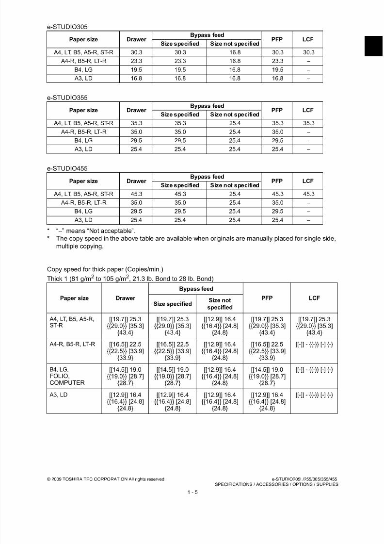
e-STUDIO305
e-STUDIO355
e-STUDIO455
* “–” means “Not acceptable”.
* The copy speed in the above table are available when originals are manually placed for single side,
multiple copying.
Copy speed for thick paper (Copies/min.)
Thick 1 (81 g/m2 to 105 g/m2, 21.3 lb. Bond to 28 lb. Bond)
Paper size Drawer Bypass feed
PFP LCFSize specified Size not specified
A4, LT, B5, A5-R, ST-R 30.3 30.3 16.8 30.3 30.3
A4-R, B5-R, LT-R 23.3 23.3 16.8 23.3 –
B4, LG 19.5 19.5 16.8 19.5 –
A3, LD 16.8 16.8 16.8 16.8 –
Paper size Drawer Bypass feed
PFP LCFSize specified Size not specified
A4, LT, B5, A5-R, ST-R 35.3 35.3 25.4 35.3 35.3
A4-R, B5-R, LT-R 35.0 35.0 25.4 35.0 –
B4, LG 29.5 29.5 25.4 29.5 –
A3, LD 25.4 25.4 25.4 25.4 –
Paper size Drawer Bypass feed
PFP LCFSize specified Size not specified
A4, LT, B5, A5-R, ST-R 45.3 45.3 25.4 45.3 45.3
A4-R, B5-R, LT-R 35.0 35.0 25.4 35.0 –
B4, LG 29.5 29.5 25.4 29.5 –
A3, LD 25.4 25.4 25.4 25.4 –
Paper size Drawer
Bypass feed
PFP LCFSize specified
Size not
specified
A4, LT, B5, A5-R,ST-R
[[19.7]] 25.3{{29.0}} [35.3]
{43.4}
[[19.7]] 25.3{{29.0}} [35.3]
{43.4}
[[12.9]] 16.4{{16.4}} [24.8]
{24.8}
[[19.7]] 25.3{{29.0}} [35.3]
{43.4}
[[19.7]] 25.3{{29.0}} [35.3]
{43.4}
A4-R, B5-R, LT-R [[16.5]] 22.5{{22.5}} [33.9]
{33.9}
[[16.5]] 22.5{{22.5}} [33.9]
{33.9}
[[12.9]] 16.4{{16.4}} [24.8]
{24.8}
[[16.5]] 22.5{{22.5}} [33.9]
{33.9}
[[-]] - {{-}} [-] {-}
B4, LG,FOLIO,
COMPUTER
[[14.5]] 19.0{{19.0}} [28.7]
{28.7}
[[14.5]] 19.0{{19.0}} [28.7]
{28.7}
[[12.9]] 16.4{{16.4}} [24.8]
{24.8}
[[14.5]] 19.0{{19.0}} [28.7]
{28.7}
[[-]] - {{-}} [-] {-}
A3, LD [[12.9]] 16.4{{16.4}} [24.8]
{24.8}
[[12.9]] 16.4{{16.4}} [24.8]
{24.8}
[[12.9]] 16.4{{16.4}} [24.8]
{24.8}
[[12.9]] 16.4{{16.4}} [24.8]
{24.8}
[[-]] - {{-}} [-] {-}

8/17/2019 Toshiba ES455 Service Manual
http://slidepdf.com/reader/full/toshiba-es455-service-manual 22/335
e-STUDIO205L/255/305/355/455 © 2009 TOSHIBA TEC CORPORATION All rights reservedSPECIFICATIONS / ACCESSORIES / OPTIONS / SUPPLIES
1 - 6
Thick 2 (106 g/m2 to 163 g/m2, 28 lb. Bond to 90 lb. Index)
Thick 3 (164 g/m2 to 209 g/m2, 90 lb. Index to 115.7 lb. Index)
* “–” means “Not acceptable”.
* Only A4/LT size is available for the LCF.
* The tolerance is within ±2.
* System copy speed
Paper size Drawer
Bypass feed
PFP LCFSize specified
Size not
specified
A4, LT, B5, A5-R,ST-R
[[-]] - {{-}} [-] {-} [[19.7]] 25.3{{29.0}} [35.3]
{43.4}
[[12.9]] 16.4{{16.4}} [24.8]
{24.8}
[[-]] - {{-}} [-] {-} [[-]] - {{-}} [-] {-}
A4-R, B5-R, LT-R [[-]] - {{-}} [-] {-} [[16.5]] 22.5
{{22.5}} [33.9]{33.9}
[[12.9]] 16.4
{{16.4}} [24.8]{24.8}
[[-]] - {{-}} [-] {-} [[-]] - {{-}} [-] {-}
B4, LG,FOLIO,COMPUTER
[[-]] - {{-}} [-] {-} [[14.5]] 19.0{{19.0}} [28.7]
{28.7}
[[12.9]] 16.4{{16.4}} [24.8]
{24.8}
[[-]] - {{-}} [-] {-} [[-]] - {{-}} [-] {-}
A3, LD [[-]] - {{-}} [-] {-} [[12.9]] 16.4{{16.4}} [24.8]
{24.8}
[[12.9]] 16.4{{16.4}} [24.8]
{24.8}
[[-]] - {{-}} [-] {-} [[-]] - {{-}} [-] {-}
Paper size Drawer
Bypass feed
PFP LCF
Size specified
Size not
specified
A4, LT, B5, A5-R,ST-R
[[-]] - {{-}} [-] {-} [[19.7]] 25.3{{29.0}} [35.3]
{43.4}
[[12.9]] 16.4{{16.4}} [24.8]
{24.8}
[[-]] - {{-}} [-] {-} [[-]] - {{-}} [-] {-}
A4-R, B5-R, LT-R [[-]] - {{-}} [-] {-} [[16.5]] 22.5{{22.5}} [33.9]
{33.9}
[[12.9]] 16.4{{16.4}} [24.8]
{24.8}
[[-]] - {{-}} [-] {-} [[-]] - {{-}} [-] {-}
B4, LG,FOLIO,COMPUTER
[[-]] - {{-}} [-] {-} [[14.5]] 19.0{{19.0}} [28.7]
{28.7}
[[12.9]] 16.4{{16.4}} [24.8]
{24.8}
[[-]] - {{-}} [-] {-} [[-]] - {{-}} [-] {-}
A3, LD [[-]] - {{-}} [-] {-} [[12.9]] 16.4{{16.4}} [24.8]
{24.8}
[[12.9]] 16.4{{16.4}} [24.8]
{24.8}
[[-]] - {{-}} [-] {-} [[-]] - {{-}} [-] {-}
A4 (%)
1 sheet 5 sheets 10 sheets 20 sheets
e-STUDIO 205L
Single-sided originals↓
Single-sided copies92 97 99 100
Single-sided originals↓
Double-sided copies83 97 99 100
Double-sided originals↓
Double-sided copies88 99 100 100
Double-sided originals↓
Single-sided copies93 99 100 100

8/17/2019 Toshiba ES455 Service Manual
http://slidepdf.com/reader/full/toshiba-es455-service-manual 23/335
© 2009 TOSHIBA TEC CORPORATION All rights reserved e-STUDIO205L/255/305/355/455SPECIFICATIONS / ACCESSORIES / OPTIONS / SUPPLIES
1 - 7
* The system copy speed, including scanning time, is available when 10 sheets of A4/LT size original
are set on RADF and one of the copy modes in the above table is selected. The period of time from
pressing [START] to the paper exit completely out of the equipment based on the actually measured
value.
* Upper drawer is selected and copying is at the non-sort mode.
* Automatic copy density, APS/AMS are turned off.
* Finisher is not installed.
e-STUDIO 255
Single-sided originals↓
Single-sided copies89 96 98 99
Single-sided originals↓
Double-sided copies78 95 98 99
Double-sided originals↓Double-sided copies
80 97 99 100
Double-sided originals↓
Single-sided copies87 98 99 100
e-STUDIO 305
Single-sided originals↓
Single-sided copies85 94 97 99
Single-sided originals↓
Double-sided copies72 93 96 98
Double-sided originals
↓Double-sided copies 67 96 98 99
Double-sided originals↓
Single-sided copies72 97 99 100
e-STUDIO 355
Single-sided originals↓
Single-sided copies88 96 97 99
Single-sided originals↓
Double-sided copies72 93 96 98
Double-sided originals↓
Double-sided copies
60 96 97 99
Double-sided originals↓
Single-sided copies64 97 99 100
e-STUDIO 455
Single-sided originals↓
Single-sided copies83 92 96 98
Single-sided originals↓
Double-sided copies61 90 94 97
Double-sided originals↓
Double-sided copies47 94 97 98
Double-sided originals↓
Single-sided copies49 96 98 99
A4 (%)
1 sheet 5 sheets 10 sheets 20 sheets

8/17/2019 Toshiba ES455 Service Manual
http://slidepdf.com/reader/full/toshiba-es455-service-manual 24/335
e-STUDIO205L/255/305/355/455 © 2009 TOSHIBA TEC CORPORATION All rights reservedSPECIFICATIONS / ACCESSORIES / OPTIONS / SUPPLIES
1 - 8
1.2 Accessories
Machine version
NAD: North America
ARD: Argentina and 220-volt South America
ASD: Hong Kong AUD: Australia
MJD: Europe
ASU: Asia
SAD: Saudi Arabia
CND: China
TWD: Taiwan
JPD: Japan
Unpacking/setup instruction 1 set
Operator’s manual 1 set (except for MJD)
Operator's manual pocket 1 pc. (for AUD)
Power cable 1 pc.
Warranty sheet 1 pc. (for NAD)
Setup report 1 set (for NAD and MJD, CND)
Drum (installed inside of the equipment) 1 pc.
Toner cartridge 1 pc. (except for NAD, MJD)
Developer material 1 pc. (except for NAD, MJD)
Control panel stopper 1 pc.
Rubber plug 6 pcs.
CD-ROM 1 set
8/17/2019 Toshiba ES455 Service Manual
http://slidepdf.com/reader/full/toshiba-es455-service-manual 25/335
© 2009 TOSHIBA TEC CORPORATION All rights reserved e-STUDIO205L/255/305/355/455SPECIFICATIONS / ACCESSORIES / OPTIONS / SUPPLIES
1 - 9
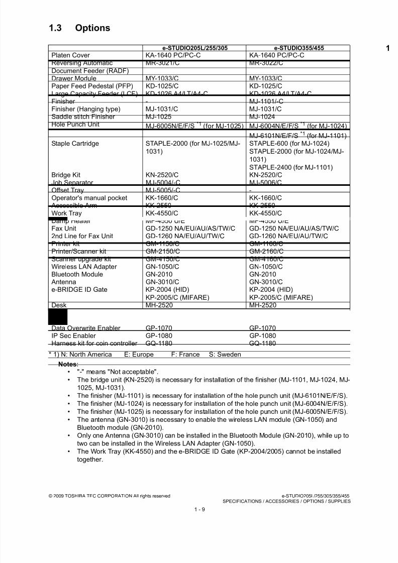
1.3 Options
* 1) N: North America E: Europe F: France S: Sweden
Notes:• "-" means "Not acceptable".
• The bridge unit (KN-2520) is necessary for installation of the finisher (MJ-1101, MJ-1024, MJ-
1025, MJ-1031).
• The finisher (MJ-1101) is necessary for installation of the hole punch unit (MJ-6101N/E/F/S).• The finisher (MJ-1024) is necessary for installation of the hole punch unit (MJ-6004N/E/F/S).
• The finisher (MJ-1025) is necessary for installation of the hole punch unit (MJ-6005N/E/F/S).
• The antenna (GN-3010) is necessary to enable the wireless LAN module (GN-1050) and
Bluetooth module (GN-2010).
• Only one Antenna (GN-3010) can be installed in the Bluetooth Module (GN-2010), while up to
two can be installed in the Wireless LAN Adapter (GN-1050).
• The Work Tray (KK-4550) and the e-BRIDGE ID Gate (KP-2004/2005) cannot be installed
together.
e-STUDIO205L/255/305 e-STUDIO355/455
Platen Cover KA-1640 PC/PC-C KA-1640 PC/PC-CReversing Automatic
Document Feeder (RADF)
MR-3021/C MR-3022/C
Drawer Module MY-1033/C MY-1033/CPaper Feed Pedestal (PFP) KD-1025/C KD-1025/CLarge Capacity Feeder (LCF) KD-1026 A4/LT/A4-C KD-1026 A4/LT/A4-CFinisher - MJ-1101/-CFinisher (Hanging type) MJ-1031/C MJ-1031/CSaddle stitch Finisher MJ-1025 MJ-1024Hole Punch Unit MJ-6005N/E/F/S *1 (for MJ-1025) MJ-6004N/E/F/S *1 (for MJ-1024)
MJ-6101N/E/F/S *1 (for MJ-1101)Staple Cartridge STAPLE-2000 (for MJ-1025/MJ-
1031)
STAPLE-600 (for MJ-1024)
STAPLE-2000 (for MJ-1024/MJ-
1031)
STAPLE-2400 (for MJ-1101)Bridge Kit KN-2520/C KN-2520/CJob Separator MJ-5004/-C MJ-5006/COffset Tray MJ-5005/-C -
Operator's manual pocket KK-1660/C KK-1660/C Accessible Arm KK-2550 KK-2550Work Tray KK-4550/C KK-4550/CDamp Heater MF-4550 U/E MF-4550 U/EFax Unit GD-1250 NA/EU/AU/AS/TW/C GD-1250 NA/EU/AU/AS/TW/C2nd Line for Fax Unit GD-1260 NA/EU/AU/TW/C GD-1260 NA/EU/AU/TW/CPrinter kit GM-1150/C GM-1160/CPrinter/Scanner kit GM-2150/C GM-2160/CScanner upgrade kit GM-4150/C GM-4160/CWireless LAN Adapter GN-1050/C GN-1050/CBluetooth Module GN-2010 GN-2010
Antenna GN-3010/C GN-3010/Ce-BRIDGE ID Gate KP-2004 (HID)
KP-2005/C (MIFARE)
KP-2004 (HID)
KP-2005/C (MIFARE)Desk MH-2520 MH-2520Meta Scan Enabler GS-1010 GS-1010External Interface Enabler GS-1020 GS-1020Data Overwrite Enabler GP-1070 GP-1070IP Sec Enabler GP-1080 GP-1080Harness kit for coin controller GQ-1180 GQ-1180

8/17/2019 Toshiba ES455 Service Manual
http://slidepdf.com/reader/full/toshiba-es455-service-manual 26/335
e-STUDIO205L/255/305/355/455 © 2009 TOSHIBA TEC CORPORATION All rights reservedSPECIFICATIONS / ACCESSORIES / OPTIONS / SUPPLIES
1 - 10
1.4 Supplies
* 1) T: Taiwan D: Asia C: China E: Europe A: Argentina/220-volt South America NONE: North America
e-STUDIO205L STUDIO255/305 e-STUDIO355/455
Drum OD-4530 /C OD-4530 /C OD-4530 /C
Toner cartridge PS-ZT4530(1) /T/D/C/E/A*1
PS-ZT4530C10K(1)PS-ZT4530(1) /T/D/C/E/A*1
PS-ZT4530C10K(1)PS-ZT4530(1) /T/D/C/E/A*1
PS-ZT4530C10K(1)
Developer D-4530 /C D-4530 /C D-4530 /C

8/17/2019 Toshiba ES455 Service Manual
http://slidepdf.com/reader/full/toshiba-es455-service-manual 27/335
© 2009 TOSHIBA TEC CORPORATION All rights reserved e-STUDIO205L/255/305/355/455SPECIFICATIONS / ACCESSORIES / OPTIONS / SUPPLIES
1 - 11
1.5 System List
1.5.1 e-STUDIO205L/255/305
Fig. 1-2
B l u e t o o t h
m o d u l e
G N - 2 0 1 0
W i r e l e s s L A N
m o d u l e
G N - 1 0 5 0 / C
S t a p l e C a r t r i d g e
S T A P L E - 2 0 0 0
H a r n e s s k i t f o r
c o i n c o n t r o l l e r
G Q - 1 1 8 0
P l a t e n C o v e r
K A - 1 6 4 0 P C / - C
B r i d g e K i t
K N - 2 5 2 0 / C
e - B R
I D G E
I D G
a t e
K P - 2 0 0 4
e - B R
I D G E
I D G
a t e
K P - 2 0 0 5 / C
A c c e s s i b l e A r m
K K - 2 5 5 0
F i n i s h e r
( H a n g i n g t y p e )
M J - 1 0 3 1 / C
2 n d L i n e f o r
F A X U n i t
G D - 1 2 6 0
N A / E U / A U / T W / C
F A X U n i t
G D - 1 2 5 0
N A / E U / A U / A S
/ T W / C
D e s k
M H
- 2 5 2 0
D r a w e r M o d u l e
M Y - 1 0 3 3 / C
L a r g e C a p a c i t y
F e e d e r ( L C F )
K D - 1 0 2 6 A 4 / L T / A 4 - C
P a p e
r F e e d
P e d e s t a l ( P F P )
K D - 1
0 2 5 / C
M e t a S c a n E n a b l e r
G S - 1 0 1 0
E x t e r n a l I n t e
r f a c e
E n a b l e r
G S - 1 0 2 0
W o r k
T r a y
K K - 4 5 5 0
A n t e
n n a
G N - 3 0 1 0 / C
O p e r a t o r ' s
m a n u a l p o c k e t
K K - 1 6 6 0 / C
I P S e c E n a b l e r
G P - 1 0 8 0
D a t a o v e r w
r i t e E n a b l e r
G P - 1 0 7 0
P r i n t e r / S c a n n e r K i t
G M - 2
1 5 0 / C
D a m p H e a t e r
M F - 4 5 5 0 U / E
P r i n t e r K i t
G M - 1
1 5 0 / C
S c a n n e r K i t
G M - 4
1 5 0 / C
J o b S e p a r a t o r
M J - 5 0 0 4 / C
O f f s e t T r a y
M J - 5 0 0 5 / C
R e
v e r s i n g A u t o m a t i c
D o c u m e n t F e e d e r ( R A D F )
M R - 3 0 2 1 / C
S a d d l e s t i t c h
F i n i s h e r
M J - 1 0 2 5
S t a p l e C a r t r i d g e
S T A P L E - 2 0 0 0
H o l e
P u n c h U n i t
M J - 6 0 0 5
N / E / F / S
8/17/2019 Toshiba ES455 Service Manual
http://slidepdf.com/reader/full/toshiba-es455-service-manual 28/335
e-STUDIO205L/255/305/355/455 © 2009 TOSHIBA TEC CORPORATION All rights reservedSPECIFICATIONS / ACCESSORIES / OPTIONS / SUPPLIES
1 - 12
1.5.2 e-STUDIO355/455
Fig. 1-3
B l u e t o o t h
m o d u l e
G N - 2 0 1 0
W i r e l e s s L A N
m o d u l e
G N - 1 0 5 0 / C
S t a p l e C a
r t r i d g e
S T A P L E - 2 0 0 0
H a r n e s s k i t f o r
c o i n c o n t r o l l e r
G Q - 1 1 8 0
P l a t e n C o
v e r
K A - 1 6 4 0 P C / - C
B r i d g e K i t
K N - 2 5 2 0 / C
e - B R I D G E
I D G a t e
K P - 2 0 0 4
e - B R I D G E
I D G a t e
K P - 2 0 0 5 / C
A c c e s s i b l e A r m
K K - 2 5 5 0
F i n i s h
e r
( H a n g i n g
t y p e )
M J - 1 0 3
1 / C
2 n d L i n e f o r
F
A X U n i t
G
D - 1 2 6 0
N A / E
U / A U / T W / C
F A X U n i t
G D - 1 2 5 0
N A / E U / A U / A S
/ T W / C
D e s k
M H - 2 5 2 0
D r a w e r M o d u l e
M Y - 1 0 3 3 / C
L a r g e C a p a c i t y
F e e d e r ( L C F )
K D - 1 0 2 6 A 4 / L T / A 4 - C
P a p e r F e e d
P e d e s t a l ( P F P )
K D - 1 0 2 5 / C
I P S e c E n a b l e r
G P - 1 0 8 0
M e t a S c a n E n a b l e r
G S - 1 0 1 0
E x t e r n a l I n t e r f a c e
E n a b l e r
G S - 1 0 2 0
W o r k T r a y
K K - 4 5 5 0
A n t e n n a
G N - 3 0 1 0 / C
O p e r a t o r ' s
m a n u a l p o c k e t
K K - 1 6 6 0 / C
D a t a o v e r w r i t e E n a b l e r
G P - 1 0 7 0
D a m p H e a t e r
M F - 4 5 5 0 U / E
S c a n n e r K i t
G M - 4 1 6 0 / C
P r i n t e r K i t
G M - 1 1 6 0 / C
P r i n t e r / S c a n n e r K i t
G M - 2 1 6 0 / C
H o l e P u n c h U n i t
M J - 6 0 0 4 N / E / F / S
R e v e r s i n g A u t o m a t i c
D o c u m e n t F e e d e r ( R A D F )
M R - 3 0 2 2 / C
F i n i s h
e r
M J - 1 1 0
1 / C
S t a p l e C a
r t r i d g e
S T A P L E - 2 4 0 0
S a d d l e s t i t c h
F i n i s h
e r
M J - 1 0
2 4
S t a p l e C a
r t r i d g e
S T A P L E - 2 0 0 0
S T A P L E
- 6 0 0
J o b S e p a r a t o r
M J - 5 0 0 6 / C
H o l e
P u n c h U n i t
M J - 6 0 0 1
N / E / F / S

8/17/2019 Toshiba ES455 Service Manual
http://slidepdf.com/reader/full/toshiba-es455-service-manual 29/335
© 2009 TOSHIBA TEC CORPORATION All rights reserved e-STUDIO205L/255/305/355/455OUTLINE OF THE MACHINE
2 - 1
2. OUTLINE OF THE MACHINE
2.1 Sectional View
Fig. 2-1 Front side view
e-STUDIO205L/255/305
B2 B1
A4 A5 A9
A2 A1 A8 A67 A3 A10 A11 A12
H5
H6
I1
J3
G8
I2
G2
H2
H4
H1
H3
G7
F8
F11
F10
F9
F12
F7
F6
F5
F4
F3
F2
C4
C3
5
2
6
C12
C11
C13
10
14
C1
C9
F1
E2
E1
E4
E3
G5
G6
G4
J1
G3
1
J2
I4
I3
D2
D3
D1
C17
C17
E6
E7
G4
H1
I1
G8
I2
G2
G7
G6
G3
G1
G5
e-STUDIO205L/255/305
B2 B1
A4 A5 A9
A2 A1 A8 A6 A7 A3 A10 A11 A12
H5
H6
I1
J3
G8
I2
G2
H2
H4
H1
H3
G7F8
F11F10
F9
F12F7
F6F5
F4F3
F2
C4C3C5C2
C6
C12C11
C13C10C14
C1
C9
F1
E2
E1
E4E3
G5
G6
G4
J1 G3G1
J2
I4I3
D2
D3
D1
C17
C20
E6
E7
G4
H1
I1G8
I2
G2G7
G6
G3G1
G5

8/17/2019 Toshiba ES455 Service Manual
http://slidepdf.com/reader/full/toshiba-es455-service-manual 30/335
e-STUDIO205L/255/305/355/455 © 2009 TOSHIBA TEC CORPORATION All rights reservedOUTLINE OF THE MACHINE
2 - 2
Fig. 2-2 Rear side view
e-STUDIO205L/255/305
A13
H8
J4
A16
I55
I6
H7
I7
D4
C18
C19
E5
H7
H8
H7
H99
F14
F13
C8
C16
C7
C15
A14 A15
e-STUDIO205L/255/305
A13
J4
A16
I5I5
I6
H7
I7
D4
C18
C19
E5
F14
F13
C8
C16C7
C15
A14 A15
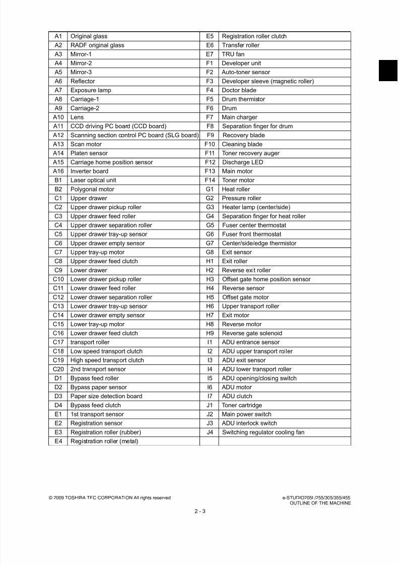
8/17/2019 Toshiba ES455 Service Manual
http://slidepdf.com/reader/full/toshiba-es455-service-manual 31/335
© 2009 TOSHIBA TEC CORPORATION All rights reserved e-STUDIO205L/255/305/355/455OUTLINE OF THE MACHINE
2 - 3
A1 Original glass E5 Registration roller clutch
A2 RADF original glass E6 Transfer roller
A3 Mirror-1 E7 TRU fan
A4 Mirror-2 F1 Developer unit
A5 Mirror-3 F2 Auto-toner sensor
A6 Reflector F3 Developer sleeve (magnetic roller)
A7 Exposure lamp F4 Doctor blade
A8 Carriage-1 F5 Drum thermistor A9 Carriage-2 F6 Drum
A10 Lens F7 Main charger
A11 CCD driving PC board (CCD board) F8 Separation finger for drum
A12 Scanning section control PC board (SLG board) F9 Recovery blade
A13 Scan motor F10 Cleaning blade
A14 Platen sensor F11 Toner recovery auger
A15 Carriage home position sensor F12 Discharge LED
A16 Inverter board F13 Main motor
B1 Laser optical unit F14 Toner motor
B2 Polygonal motor G1 Heat roller
C1 Upper drawer G2 Pressure roller C2 Upper drawer pickup roller G3 Heater lamp (center/side)
C3 Upper drawer feed roller G4 Separation finger for heat roller
C4 Upper drawer separation roller G5 Fuser center thermostat
C5 Upper drawer tray-up sensor G6 Fuser front thermostat
C6 Upper drawer empty sensor G7 Center/side/edge thermistor
C7 Upper tray-up motor G8 Exit sensor
C8 Upper drawer feed clutch H1 Exit roller
C9 Lower drawer H2 Reverse exit roller
C10 Lower drawer pickup roller H3 Offset gate home position sensor
C11 Lower drawer feed roller H4 Reverse sensor
C12 Lower drawer separation roller H5 Offset gate motor C13 Lower drawer tray-up sensor H6 Upper transport roller
C14 Lower drawer empty sensor H7 Exit motor
C15 Lower tray-up motor H8 Reverse motor
C16 Lower drawer feed clutch H9 Reverse gate solenoid
C17 transport roller I1 ADU entrance sensor
C18 Low speed transport clutch I2 ADU upper transport roller
C19 High speed transport clutch I3 ADU exit sensor
C20 2nd transport sensor I4 ADU lower transport roller
D1 Bypass feed roller I5 ADU opening/closing switch
D2 Bypass paper sensor I6 ADU motor
D3 Paper size detection board I7 ADU clutchD4 Bypass feed clutch J1 Toner cartridge
E1 1st transport sensor J2 Main power switch
E2 Registration sensor J3 ADU interlock switch
E3 Registration roller (rubber) J4 Switching regulator cooling fan
E4 Registration roller (metal)
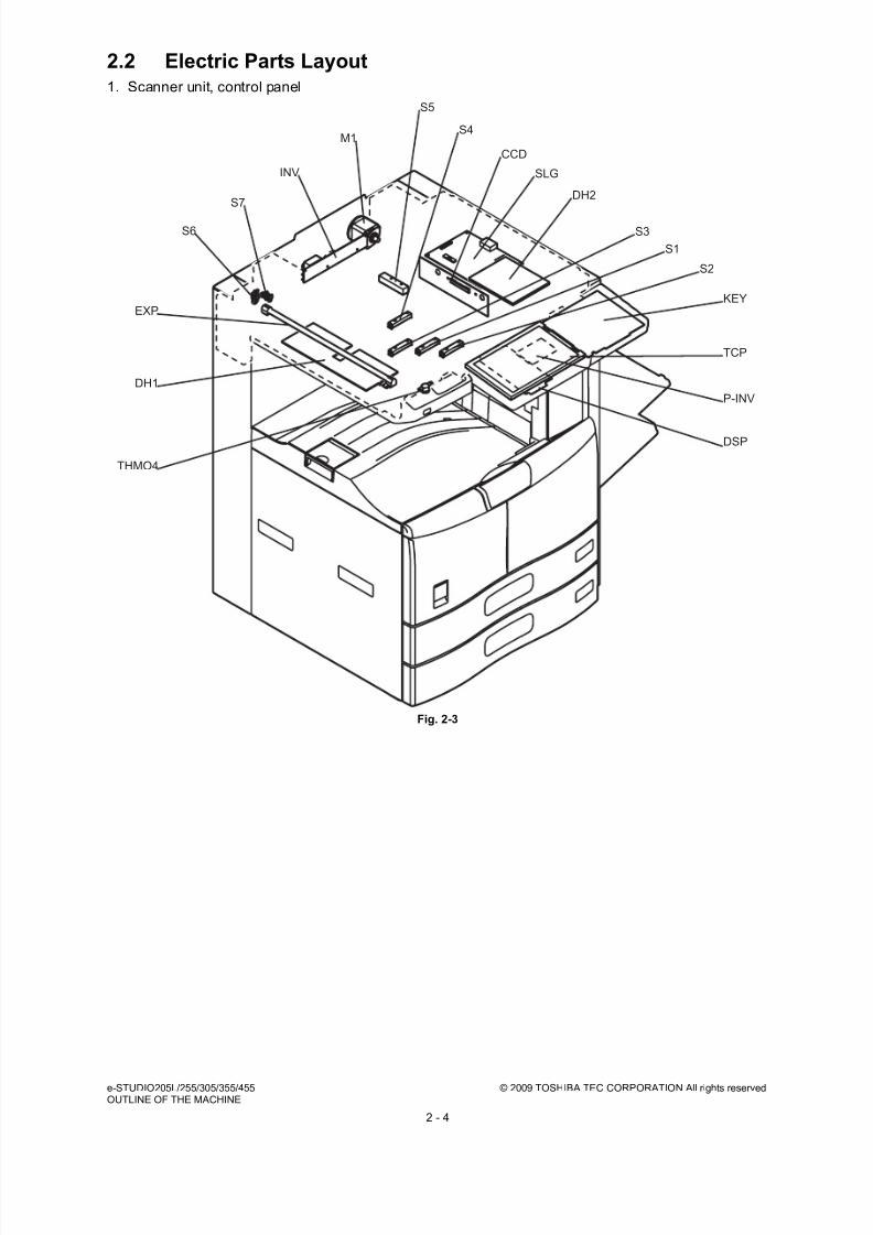
8/17/2019 Toshiba ES455 Service Manual
http://slidepdf.com/reader/full/toshiba-es455-service-manual 32/335
e-STUDIO205L/255/305/355/455 © 2009 TOSHIBA TEC CORPORATION All rights reservedOUTLINE OF THE MACHINE
2 - 4
2.2 Electric Parts Layout1. Scanner unit, control panel
Fig. 2-3
M1
S5
S4
S1
S3
KEY
TCP
DSP
P-INV
S7
INV
S6
DH1
DH2
CCD
SLG
EXP
S2
THMO4

8/17/2019 Toshiba ES455 Service Manual
http://slidepdf.com/reader/full/toshiba-es455-service-manual 33/335
© 2009 TOSHIBA TEC CORPORATION All rights reserved e-STUDIO205L/255/305/355/455OUTLINE OF THE MACHINE
2 - 5
2. Power supply, developer unit
Fig. 2-4
SW1
DH3
ERS
THMS4
SW3
EPU
SW2
LVPS
HVPS
M2
THMO3
S8
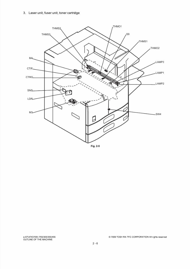
8/17/2019 Toshiba ES455 Service Manual
http://slidepdf.com/reader/full/toshiba-es455-service-manual 34/335
e-STUDIO205L/255/305/355/455 © 2009 TOSHIBA TEC CORPORATION All rights reservedOUTLINE OF THE MACHINE
2 - 6
3. Laser unit, fuser unit, toner cartridge
Fig. 2-5
THMS3
THMS2
THMS1
S9
THMO1
LAMP2
SW4
LAMP1
LAMP3
M4
CTIF
CTRG
M3
LDR
SNS
THMO2

8/17/2019 Toshiba ES455 Service Manual
http://slidepdf.com/reader/full/toshiba-es455-service-manual 35/335
© 2009 TOSHIBA TEC CORPORATION All rights reserved e-STUDIO205L/255/305/355/455OUTLINE OF THE MACHINE
2 - 7
4. Drive unit
e-STUDIO205L/255/305
Fig. 2-6
IMG
MOT
M5
HDD
FUS
M7
M8
M6
LGC
SYS
S25

8/17/2019 Toshiba ES455 Service Manual
http://slidepdf.com/reader/full/toshiba-es455-service-manual 36/335
e-STUDIO205L/255/305/355/455 © 2009 TOSHIBA TEC CORPORATION All rights reservedOUTLINE OF THE MACHINE
2 - 8
e-STUDIO355/455
Fig. 2-7
IMG
MOT2
M5
HDD
FUS
M7
M8
M6
LGC
SYS
S25
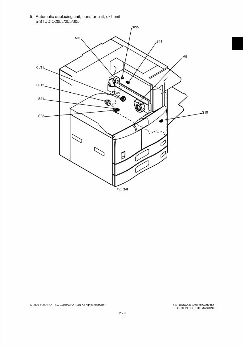
8/17/2019 Toshiba ES455 Service Manual
http://slidepdf.com/reader/full/toshiba-es455-service-manual 37/335
© 2009 TOSHIBA TEC CORPORATION All rights reserved e-STUDIO205L/255/305/355/455OUTLINE OF THE MACHINE
2 - 9
5. Automatic duplexing unit, transfer unit, exit unit
e-STUDIO205L/255/305
Fig. 2-8
M10
CLT1
S10
S11
SW5
M9
CLT2
S21
S22

8/17/2019 Toshiba ES455 Service Manual
http://slidepdf.com/reader/full/toshiba-es455-service-manual 38/335
e-STUDIO205L/255/305/355/455 © 2009 TOSHIBA TEC CORPORATION All rights reservedOUTLINE OF THE MACHINE
2 - 10
e-STUDIO355/455
Fig. 2-9
M14
M10
S24
CLT1
S10
M13
S11
SOL1
S23
SW5
M9
CLT2
S21
S22
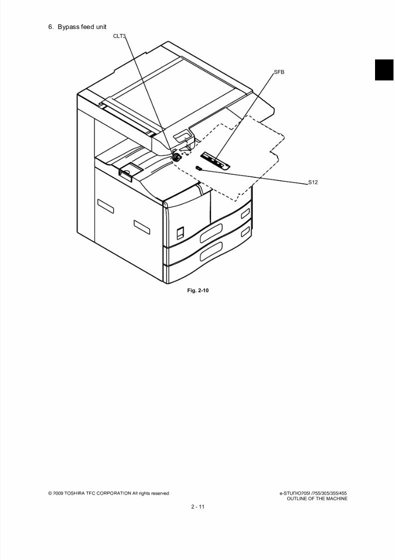
8/17/2019 Toshiba ES455 Service Manual
http://slidepdf.com/reader/full/toshiba-es455-service-manual 39/335
© 2009 TOSHIBA TEC CORPORATION All rights reserved e-STUDIO205L/255/305/355/455OUTLINE OF THE MACHINE
2 - 11
6. Bypass feed unit
Fig. 2-10
S12
SFB
CLT3

8/17/2019 Toshiba ES455 Service Manual
http://slidepdf.com/reader/full/toshiba-es455-service-manual 40/335
e-STUDIO205L/255/305/355/455 © 2009 TOSHIBA TEC CORPORATION All rights reservedOUTLINE OF THE MACHINE
2 - 12
7. Drawer unit
Fig. 2-11
S13
S20
S19
S17
S16
CLT5
S18
S14
M12
SW7
SW6
S15
CLT4
M11 CLT6
CLT7

8/17/2019 Toshiba ES455 Service Manual
http://slidepdf.com/reader/full/toshiba-es455-service-manual 41/335
© 2009 TOSHIBA TEC CORPORATION All rights reserved e-STUDIO205L/255/305/355/455OUTLINE OF THE MACHINE
2 - 13
2.3 Symbols and Functions of Various ComponentsThe column "P-I" shows the page and item number in the parts list.
1. Motors
2. Sensors and switches
Symbol Name Function Remarks P-I
M1 SCAN-MOTScan motor
Driving the carriages Fig. 2-3 15-14
M2 PU-FANProcess unit fan
Cooling down the process unit Fig. 2-4 1-25
M3 POL-MOTPolygonal motor
Driving the polygonal mirror Fig. 2-5 11-1
M4 TNR-MOTToner motor
Transporting toner from the tonercartridge to the developer unit
Fig. 2-5 14-29
M5 ADU-MOT ADU motor
Driving the automatic duplexing unit Fig. 2-6Fig. 2-7
8-1
M6 SYS-FAN-MOTSYS/HDD cooling fan
Cooling down the SYS board and harddisk
Fig. 2-6Fig. 2-7
9-3
M7 POW-FANSwitching regulator cooling fan
Cooling down the High-voltagetransformer and switching regulator
Fig. 2-6Fig. 2-7
4-14
M8 MAIN-MOTMain motor
Driving the drum, developer unit, fuserunit, registration roller, transport rollers,feed rollers and pickup rollers
Fig. 2-6Fig. 2-7
14-21
M9 TRU-FANTRU fan
Assisting the paper separation process Fig. 2-8Fig. 2-9
13-9
M10 EXIT-MOTExit motor
Driving the exit roller Fig. 2-8Fig. 2-9
33-18
M11 TRAY-U-MOTUpper tray-up motor
Driving the lifting movement of trays inupper drawer
Fig. 2-11 7-18
M12 TRAY-L-MOTLower tray-up motor
Driving the lifting movement of trays inlower drawer
Fig. 2-11 7-18
M13 OCT-GT-MOToffset gate motor
Driving the offset gate* e-STUDIO355/455 only
Fig. 2-9 34-24
M14 REV-MOTReverse motor
Driving the reverse roller * e-STUDIO355/455 only
Fig. 2-9 34-22
Symbol Name Function Remarks P-I
S1-5 APS1-3, APS-C, APS-R Automatic original detection sensor
Original size detection Fig. 2-3 S1-4:12-16S5:
12-17
S6 PLTN-SNRPlaten sensor Opening/closing detection of platencover or RADF Fig. 2-3 15-31
S7 HOME-SNRCarriage home position sensor
Carriage home position detection Fig. 2-3 12-25
S8 ATTNR-SNR Auto-toner sensor
Detecting the density of toner in thedeveloper unit
Fig. 2-4 28-20
S9 EXIT-SWExit sensor
Detecting the transporting paper at theexit section
Fig. 2-5 31-27
S10 ADU-TR1-SNR ADU exit sensor
Detecting the transporting paper inautomatic duplexing unit
Fig. 2-8Fig. 2-9
35-15

8/17/2019 Toshiba ES455 Service Manual
http://slidepdf.com/reader/full/toshiba-es455-service-manual 42/335
e-STUDIO205L/255/305/355/455 © 2009 TOSHIBA TEC CORPORATION All rights reservedOUTLINE OF THE MACHINE
2 - 14
S11 ADU-TR2-SNR ADU entrance sensor
Detecting the transporting paper atautomatic duplexing unit entrancesection
Fig. 2-8Fig. 2-9
35-15
S12 SFB-EMP-SNRBypass paper sensor
Detecting presence/absence of paperon the bypass tray
Fig. 2-10 35-15
S13 FEED-COV-SNRFeed cover opening/closing sensor
Feed cover opening/closing detection Fig. 2-11 18-6
S14 2ND-FEED-SNR2nd transport sensor
Detecting the transport paper and jamming fed from the lower drawer orPFP/LCF
Fig. 2-11 18-6
S15 NEAR-EMP-U-SNRUpper drawer paper stock sensor
Paper amount detection in the upperdrawer
Fig. 2-11 16-18
S16 TOP-U-SNRUpper drawer tray-up sensor
Position detection of the lifting tray of theupper drawer
Fig. 2-11 16-18
S17 EMP-U-SNRUpper drawer empty sensor
Paper presence/absence detection inthe upper drawer
Fig. 2-11 16-18
S18 NEAR-EMP-L-SNRLower drawer paper stock sensor
Paper amount detection in the lowerdrawer
Fig. 2-11 16-18
S19 TOP-L-SNRLower drawer tray-up sensor
Position detection of the lifting tray of thelower drawer
Fig. 2-11 16-18
S20 EMP-L-SNRLower drawer empty sensor
Paper presence/absence detection inthe lower drawer
Fig. 2-11 16-18
S21 1ST-FEED-SNR1st transport sensor
Detecting the transporting paper and jamming fed from the bypass, drawer, ADU
Fig. 2-8Fig. 2-9
21-14
S22 RGST-SNRRegistration sensor
Detecting the paper transport at theregistration roller section
Fig. 2-8Fig. 2-9
21-14
S23 REV-SNRReverse sensor
Detecting the transporting paper at thereverse section* e-STUDIO355/455 only
Fig. 2-9 34-2
S24 OCT-HOME-SNROffset gate home position sensor
Offset gate home position detection* e-STUDIO355/455 only
Fig. 2-9 33-25
S25 TEMP/HUMI-SNRTemperature/humidity sensor
Detecting the temperature and humidityof the outside air taken into theequipment
Fig. 2-6Fig. 2-7
4-16
SW1 MAIN-SWMain switch
Turning ON/OFF of the equipment Fig. 2-4 4-3
SW2 FRNT-COV-INTLCK-SWFront cover interlock switch
Supplying or shutting off AC power tothe switching regulator (voltage-generating circuit interlocked with these
covers) according to the opening/closingstatus of the front cover (Cover open:Shut off)
Fig. 2-4 1-11
SW3 ADU-INTLCK-SW ADU interlock switch
Supplying or shutting off AC power tothe switching regulator (voltage-generating circuit interlocked with thesecovers) according to the opening/closingstatus of the automatic duplexing unit(Cover open: Shut off)
Fig. 2-4 5-18
SW4 FRONT-COV-SWFront cover switch
Detecting opening/closing of the frontcover
Fig. 2-5 1-4
Symbol Name Function Remarks P-I
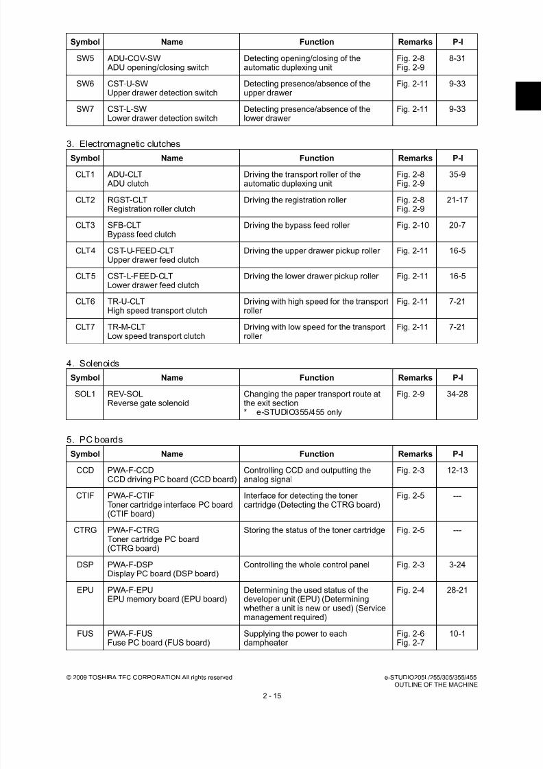
8/17/2019 Toshiba ES455 Service Manual
http://slidepdf.com/reader/full/toshiba-es455-service-manual 43/335
© 2009 TOSHIBA TEC CORPORATION All rights reserved e-STUDIO205L/255/305/355/455OUTLINE OF THE MACHINE
2 - 15
3. Electromagnetic clutches
4. Solenoids
5. PC boards
SW5 ADU-COV-SW ADU opening/closing switch
Detecting opening/closing of theautomatic duplexing unit
Fig. 2-8Fig. 2-9
8-31
SW6 CST-U-SWUpper drawer detection switch
Detecting presence/absence of theupper drawer
Fig. 2-11 9-33
SW7 CST-L-SWLower drawer detection switch
Detecting presence/absence of thelower drawer
Fig. 2-11 9-33
Symbol Name Function Remarks P-I
CLT1 ADU-CLT ADU clutch
Driving the transport roller of theautomatic duplexing unit
Fig. 2-8Fig. 2-9
35-9
CLT2 RGST-CLTRegistration roller clutch
Driving the registration roller Fig. 2-8Fig. 2-9
21-17
CLT3 SFB-CLTBypass feed clutch
Driving the bypass feed roller Fig. 2-10 20-7
CLT4 CST-U-FEED-CLTUpper drawer feed clutch
Driving the upper drawer pickup roller Fig. 2-11 16-5
CLT5 CST-L-FEED-CLTLower drawer feed clutch
Driving the lower drawer pickup roller Fig. 2-11 16-5
CLT6 TR-U-CLTHigh speed transport clutch
Driving with high speed for the transportroller
Fig. 2-11 7-21
CLT7 TR-M-CLTLow speed transport clutch
Driving with low speed for the transportroller
Fig. 2-11 7-21
Symbol Name Function Remarks P-I
SOL1 REV-SOL
Reverse gate solenoid
Changing the paper transport route at
the exit section* e-STUDIO355/455 only
Fig. 2-9 34-28
Symbol Name Function Remarks P-I
CCD PWA-F-CCDCCD driving PC board (CCD board)
Controlling CCD and outputting theanalog signal
Fig. 2-3 12-13
CTIF PWA-F-CTIFToner cartridge interface PC board(CTIF board)
Interface for detecting the tonercartridge (Detecting the CTRG board)
Fig. 2-5 ---
CTRG PWA-F-CTRG
Toner cartridge PC board(CTRG board)
Storing the status of the toner cartridge Fig. 2-5 ---
DSP PWA-F-DSPDisplay PC board (DSP board)
Controlling the whole control panel Fig. 2-3 3-24
EPU PWA-F-EPUEPU memory board (EPU board)
Determining the used status of thedeveloper unit (EPU) (Determiningwhether a unit is new or used) (Servicemanagement required)
Fig. 2-4 28-21
FUS PWA-F-FUSFuse PC board (FUS board)
Supplying the power to eachdampheater
Fig. 2-6Fig. 2-7
10-1
Symbol Name Function Remarks P-I

8/17/2019 Toshiba ES455 Service Manual
http://slidepdf.com/reader/full/toshiba-es455-service-manual 44/335
e-STUDIO205L/255/305/355/455 © 2009 TOSHIBA TEC CORPORATION All rights reservedOUTLINE OF THE MACHINE
2 - 16
6. Lamps and heaters
IMG PWA-F-IMGImage processing PC board(IMG board)
Controlling the image processing Fig. 2-6Fig. 2-7
9-16
KEY PWA-F-KEYKey control PC board (KEY board)
Controlling the key switches and LEDs Fig. 2-3 3-25
LDR PWA-F-LDRLaser driving PC board
(LDR board)
Driving the laser diode Fig. 2-5 11-1
LGC PWA-F-LGCLogic PC board (LGC board)
Controlling the print engine section Fig. 2-6Fig. 2-7
9-13
MOT PWA-F-MOTMOT board
Driving the automatic duplexing unit andexit section* e-STUDIO205/255/305 only
Fig. 2-6 14-22
MOT2 PWA-F-MOT2MOT2 board
Driving the automatic duplexing unit, exitsection, and paper handling option* e-STUDIO355/455 only
Fig. 2-7 14-22
SFB PWA-F-SFBPaper size detection board
Detecting the width of paper on thebypass tray
Fig. 2-10 19-13
SLG PWA-F-SLGScanning section control PC board(SLG board)
Controlling the original scanning section Fig. 2-3 12-12
SNS PWA-F-SNSH-sync signal detection PC board(SNS board)
Detection of the laser beam position Fig. 2-5 11-1
SYS PWA-F-SYSSystem control PC board(SYS board)
Controlling the whole system and imageprocessing
Fig. 2-6Fig. 2-7
9-10
Symbol Name Function Remarks P-I
DH1 SCN-L-DHScanner damp heater (Left)
Preventing condensation of the mirrorsof the carriages
Fig. 2-3 12-20
DH2 SCN-R-DHScanner damp heater (Right)
Preventing condensation of the lens Fig. 2-3 12-18
DH3 DRM-DHDrum damp heater
Preventing condensation of the drum Fig. 2-4 5-20
ERS LP-ERSDischarge LED
Removing the residual charge from thedrum surface
Fig. 2-4 27-32
EXP LP-EXPOExposure lamp
Exposing the original to the light Fig. 2-3 23-3
LAMP1 CNTR-LAMPCenter heater lamp
Heating the center section of fuser roller Fig. 2-5 31-19
LAMP2 SIDE-LAMPSide heater lamp
Heating the section of both sides offuser roller
Fig. 2-5 31-20
LAMP3 LAMP-TRIPLESub heater lamp
Sub heating of the fuser roller * e-STUDIO355/455 only
Fig. 2-5 31-21
Symbol Name Function Remarks P-I
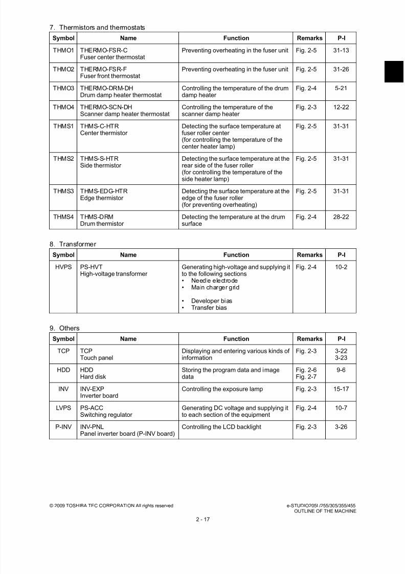
8/17/2019 Toshiba ES455 Service Manual
http://slidepdf.com/reader/full/toshiba-es455-service-manual 45/335
© 2009 TOSHIBA TEC CORPORATION All rights reserved e-STUDIO205L/255/305/355/455OUTLINE OF THE MACHINE
2 - 17
7. Thermistors and thermostats
8. Transformer
9. Others
Symbol Name Function Remarks P-I
THMO1 THERMO-FSR-CFuser center thermostat
Preventing overheating in the fuser unit Fig. 2-5 31-13
THMO2 THERMO-FSR-FFuser front thermostat
Preventing overheating in the fuser unit Fig. 2-5 31-26
THMO3 THERMO-DRM-DHDrum damp heater thermostat
Controlling the temperature of the drumdamp heater
Fig. 2-4 5-21
THMO4 THERMO-SCN-DHScanner damp heater thermostat
Controlling the temperature of thescanner damp heater
Fig. 2-3 12-22
THMS1 THMS-C-HTRCenter thermistor
Detecting the surface temperature atfuser roller center (for controlling the temperature of thecenter heater lamp)
Fig. 2-5 31-31
THMS2 THMS-S-HTRSide thermistor
Detecting the surface temperature at therear side of the fuser roller (for controlling the temperature of theside heater lamp)
Fig. 2-5 31-31
THMS3 THMS-EDG-HTR
Edge thermistor
Detecting the surface temperature at the
edge of the fuser roller (for preventing overheating)
Fig. 2-5 31-31
THMS4 THMS-DRMDrum thermistor
Detecting the temperature at the drumsurface
Fig. 2-4 28-22
Symbol Name Function Remarks P-I
HVPS PS-HVTHigh-voltage transformer
Generating high-voltage and supplying itto the following sections• Needle electrode• Main charger grid
• Developer bias• Transfer bias
Fig. 2-4 10-2
Symbol Name Function Remarks P-I
TCP TCPTouch panel
Displaying and entering various kinds ofinformation
Fig. 2-3 3-223-23
HDD HDDHard disk
Storing the program data and imagedata
Fig. 2-6Fig. 2-7
9-6
INV INV-EXPInverter board
Controlling the exposure lamp Fig. 2-3 15-17
LVPS PS-ACCSwitching regulator
Generating DC voltage and supplying itto each section of the equipment
Fig. 2-4 10-7
P-INV INV-PNLPanel inverter board (P-INV board)
Controlling the LCD backlight Fig. 2-3 3-26

8/17/2019 Toshiba ES455 Service Manual
http://slidepdf.com/reader/full/toshiba-es455-service-manual 46/335
e-STUDIO205L/255/305/355/455 © 2009 TOSHIBA TEC CORPORATION All rights reservedOUTLINE OF THE MACHINE
2 - 18
2.4 System block diagram
e-STUDIO205L/255/305
Fig. 2-12
P F P / L C F
C C D
S c a n n e r
C P U
S R A M
F l a s h
R O M
A F E
I / O
A F E
I m a g e d a t a
A S I C
E n g i n e -
C P U
I / O
F l a s h
R O M
E t h e r P H Y
A S I C
L V D S
d r i v e r
L V D S
r e c e i v e r
R T C
D D R 2 D I M M
L A N
( 1 0 B A S E - T / 1 0 0 B A S E - T
X )
P C
S o C
( S y s t e m o n c h i p )
A S I C
C C D b o a r d
R A D F b o a r d
S L G b o a r d
S Y S b o a r d
I M G b o a r d
L G C b o
a r d
1 6
U S B
H u b
P C I
S A T A 1 5 0
S R A M
1 6
1 6
1 6
6 4 1
6
8
8
R A D F
C P U
E E P R O M
8
8
8
S R A M
E E P
R O M
1 6
8
F A X
u n i t
1 6
1 6
P C I E x p r e s s X 1
F l a s h
R O M
e - B
R I D G E I D
G a t e
( M I F A R E )
e - B
R I D G E I D
G a t e
( H I D )
W i r e l w s s L A N
a d a p t e r
S A T A H D D
( 2 . 5 i n c h )
F r o n t
U S B ( h o s t )
R e a r
U S B ( h o s t )
R e a r
U S B ( h o s t )
U S B 2 . 0
( d e v i c e )
O n e - t i m e
d o n g l e
C o n t r o l p a n e l
: O p t i o n
A S I C
A S I C L
D R b o a r d
L a s e r b e a m s e n s o r
S N S b o a r d
L a s e r U n i t
1 6
I P C
O f f s e t t r a y
J o b s e p a r a t o r
A S I C
8
B r i d g e u n i t
K e y c o p y c o u n t e r
C o p y k e y c a r d
H V T
A D U
B y p a s s U n i t
S e n s o r s
M o t o r s
S w i t c h e s
S o l e n o i d s
C l u t c h e s
- D a t a o v e r w r i t e e n a b l e
r
- M e t a s c a n e n a b l e r
- E x t e r n a l i n t e r f a c e
e n a b l e r
- I P S e c e n a b l e r
B l u e t o o t h
m o d u l e
- P r i n t e r k i t
- P r i n t e r / S c a n n e r k i t
- S c a n n e r k i t
E n a b l e r
B a t t e r y
S R A M b o a r d
D o w n l o a d j i g
( S Y S )
B u s b u f f e r
B u s b u f f e r
B u s b u f f e r
B u s b u f f e r
I m a g e d a t a
F i n i s h e r
F i n i s h e r L
a s e r
d i o d e I m
a g e d a t a
I m a g e d a t a
A F E
I m a g e d a t a
I m a g e d a t a
D o w n l o a d j i g
( S L G )
D o w n l o a d j i g
( R A D F )
D / A
c o n v e r t e r
D o w n l o a d j i g
( L G C )
1 6

8/17/2019 Toshiba ES455 Service Manual
http://slidepdf.com/reader/full/toshiba-es455-service-manual 47/335
© 2009 TOSHIBA TEC CORPORATION All rights reserved e-STUDIO205L/255/305/355/455OUTLINE OF THE MACHINE
2 - 19
e-STUDIO355/455
Fig. 2-13
P F P / L C F
C C D
S c a n n e r
C P U
S R A M
F l a s h
R O M
I / O
I m a g e d a t a
A S I C
I / O
E t h e r P H Y
A S I C
L V D S
d r i v e r
L V D S
r e c e i v e r
R T C
D D R 2 D I M M
L A N
( 1 0 B A S E - T / 1 0 0 B A S E - T X )
P C
S
o C
( S y s t e m
o n c h i p )
A S I C
C C D b o a r d
R A D F b o
a r d
S
L G b o a r d
S Y S
b o a r d
I M G b o a r d
L G C b o a r d
1 6
U S B
H u b
P C I
S A T A 1 5 0
S R A M
1 6
1 6
1 6
6 4 1
6
8
8
R A D F
C P U
E E P R O M
8
8
8
1 6
8
F A X
u n i t
1 6
1 6
P C I E x p r e s s X 1
F l a s h
R O M
e - B
R I D G E
I D G
a t e
( M I F A R E )
e - B
R I D G E
I D G
a t e
( F e l i C a )
W i r e l w s s L A N
a d a p t e r
S A T A H D D
( 2 . 5
i n c h )
F r o n t
U S B ( h o s t )
R e a r
U S B ( h o s t )
R e a r
U S B ( h o s t )
U S B 2 . 0
( d e v i c e )
O n e - t i m e
d o n g l e
C o n t r o l p a n e l
: O p t i o n
A S I C
A S I C L
D R b o a r d
L a s e r b e a m s e n s o r
S N S b o a r d
L a s e r U n i t
M O T 2
b o a r d
1 6
I P C
O f f s e t t r a y
J o b s e p a r a t o r
A S I C
8
B r i d g e u n i t
K e y c o p y c o u n t e r
C o p y k e y c a r d
H V T
A D U
B y p a s s U n i t
S e n s o r s
M o t o r s
S w i t c h e s
S o l e n o i d s
C l u t c h e s
- D a t a o v e r w r i t e e n a b l e r
- M
e t a s c a n e n a b l e r
- E
x t e r n a l i n t e r f a c e
e n a b l e r
- I P S e c e n a b l e r
B l u e t o o t h
m o d u l e
- P
r i n t e r k i t
- P
r i n t e r / S c a n n e r k i t
- S
c a n n e r k i t
B a t t e r y
S R A M b o a r d
D o w n l o a d j i g
( S Y S )
B u s b u f f e r
B u s b u f f e r
B u s b u f f e r
B u s b u f f e r
I m
a g e d a t a
F i n i s h e r
F i n i s h e r L
a s e r
d i o d e
I m a g e d a t a
D
o w n l o a d j i g
( S L G )
D o w n l o a d j i g
( R A D F )
D / A
c o n v e r t e r
E n g i n e -
C P U
F l a s h
R
O M
S R
A M
E E P
R O M
E n a b l e r
A F E
A F E
I m a g e d a t a
I m a g e d a t a
A F E
I m a g e d a t a
D o w n l o a d j i g
( L G C )
1 6

8/17/2019 Toshiba ES455 Service Manual
http://slidepdf.com/reader/full/toshiba-es455-service-manual 48/335
e-STUDIO205L/255/305/355/455 © 2009 TOSHIBA TEC CORPORATION All rights reservedOUTLINE OF THE MACHINE
2 - 20
2.5 Installation and Replacement of Covers
2.5.1 Front cover
2.5.2 Front upper cover
(1) Open the front cover.
Fig. 2-14
(2) Slide the upper hinge to the left side while
holding it down, and then take off the upperhinge.
(3) Take off the lower hinge by lifting up the front
cover. Then take off the front cover.
Fig. 2-15
(1) Remove 1 screw and take off the front upper
cover.
Fig. 2-16
Front cover
Hinge
Hinge
Front upper cover

8/17/2019 Toshiba ES455 Service Manual
http://slidepdf.com/reader/full/toshiba-es455-service-manual 49/335
© 2009 TOSHIBA TEC CORPORATION All rights reserved e-STUDIO205L/255/305/355/455OUTLINE OF THE MACHINE
2 - 21
2.5.3 Front lower cover
2.5.4 Left upper cover
(1) Open the front upper cover.
P.2-20 "2.5.2 Front upper cover"
(2) Remove 2 screws and then take off the
control panel unit.
(3) Disconnect the USB port from the front lower
cover.
Fig. 2-17
(4) Remove 2 screws and pull the left side of the
front lower cover toward you. Then take off
the front lower cover by sliding it to the left
side.
Fig. 2-18
(1) Remove 2 screws and take off the left upper
cover.
Fig. 2-19
USB port
Left side offront Lowercover
Left upper cover
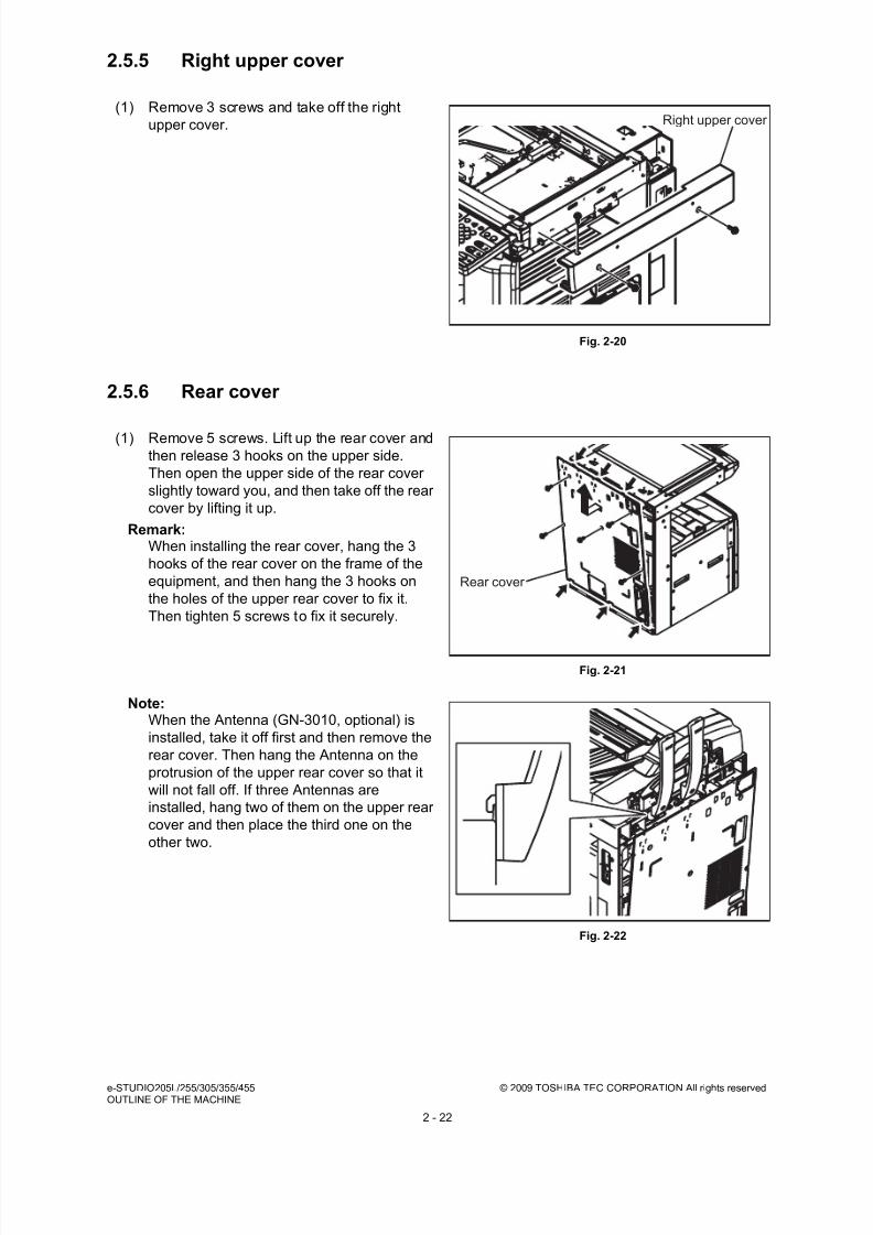
8/17/2019 Toshiba ES455 Service Manual
http://slidepdf.com/reader/full/toshiba-es455-service-manual 50/335
e-STUDIO205L/255/305/355/455 © 2009 TOSHIBA TEC CORPORATION All rights reservedOUTLINE OF THE MACHINE
2 - 22
2.5.5 Right upper cover
2.5.6 Rear cover
(1) Remove 3 screws and take off the right
upper cover.
Fig. 2-20
(1) Remove 5 screws. Lift up the rear cover and
then release 3 hooks on the upper side.
Then open the upper side of the rear cover
slightly toward you, and then take off the rear
cover by lifting it up.
Remark:When installing the rear cover, hang the 3
hooks of the rear cover on the frame of the
equipment, and then hang the 3 hooks on
the holes of the upper rear cover to fix it.
Then tighten 5 screws to fix it securely.
Note:When the Antenna (GN-3010, optional) is
installed, take it off first and then remove the
rear cover. Then hang the Antenna on the
protrusion of the upper rear cover so that it
will not fall off. If three Antennas are
installed, hang two of them on the upper rear
cover and then place the third one on the
other two.
Fig. 2-21
Fig. 2-22
Right upper cover
Rear cover

8/17/2019 Toshiba ES455 Service Manual
http://slidepdf.com/reader/full/toshiba-es455-service-manual 51/335
© 2009 TOSHIBA TEC CORPORATION All rights reserved e-STUDIO205L/255/305/355/455OUTLINE OF THE MACHINE
2 - 23
2.5.7 Upper rear cover
2.5.8 Left rear cover
2.5.9 Inner tray
(1) Take off the RADF or platen cover.
(2) Take off the left upper cover
( P.2-21 "2.5.4 Left upper cover").
(3) Take off the right upper cover.
( P.2-22 "2.5.5 Right upper cover").
(4) Take off the rear cover.
( P.2-22 "2.5.6 Rear cover").(5) Remove 2 screws and take off the upper rear
cover.
Fig. 2-23
(1) Remove 1 screw and then take off the left
rear cover by releasing 2 hooks.
Remark:When installing the left rear cover, hang the 2
hooks of the left rear cover on the frame of
the equipment, and then fix it with 1 screw.
Fig. 2-24
(1) Open the front cover and then take off the
toner cartridge.
(2) Remove 2 tap-tight screws, and then take off
the inner tray.
Fig. 2-25
Upper rear cover
Left rear cover
Inner tray

8/17/2019 Toshiba ES455 Service Manual
http://slidepdf.com/reader/full/toshiba-es455-service-manual 52/335
e-STUDIO205L/255/305/355/455 © 2009 TOSHIBA TEC CORPORATION All rights reservedOUTLINE OF THE MACHINE
2 - 24
2.5.10 Left cover
2.5.11 Tray back cover
2.5.12 Connecting port cover
(1) Remove 2 tap-tight screws and 5 screws.
Then take off the left cover.
Fig. 2-26
(1) Take off the left rear cover
( P.2-23 "2.5.8 Left rear cover").
(2) Take off the inner tray
( P.2-23 "2.5.9 Inner tray").
(3) Take off the tray back cover.
Fig. 2-27
(1) Open the automatic duplexing unit.
(2) Remove 1 screw and then take off the
connecting port cover by releasing 2 hooks.
Remark:When installing the connecting port cover,
hang the 2 hooks of the connecting portcover on the frame of the equipment, and
then fix it with 1 screw.
Fig. 2-28
Left cover
Tray back cover
Connecting port cover

8/17/2019 Toshiba ES455 Service Manual
http://slidepdf.com/reader/full/toshiba-es455-service-manual 53/335
© 2009 TOSHIBA TEC CORPORATION All rights reserved e-STUDIO205L/255/305/355/455OUTLINE OF THE MACHINE
2 - 25
2.5.13 Right rear cover
[A] e-STUDIO205L/255/305
[B] e-STUDIO355/455
2.5.14 Right front cover
(1) Take off the connecting port cover.
( P.2-24 "2.5.12 Connecting port cover").
(2) Open the transfer cover.
(3) Release 3 hooks by sliding the right rear
cover to the right side, and then take off theright rear cover.
Fig. 2-29
(1) Take off the connecting port cover.
( P.2-24 "2.5.12 Connecting port cover").
(2) Open the transfer cover.
(3) Release 2 hooks by sliding the right rear
cover to the right side, and then take off the
right rear cover.
Fig. 2-30
(1) Take off the front cover.
( P.2-22 "2.5.6 Rear cover").
(2) Take off the process unit.
( P.11-12 "11.6.1 Process unit").
(3) Pull out the upper and lower drawers.
(4) Open the feed cover.
(5) Remove 2 screws. Release 4 hooks by
sliding the right front cover downward, and
then take off the right front cover by pulling
out toward you.
Remark:When installing the right front cover, hang
the 4 hooks of the right front cover on the
frame of the equipment, and then fix it with 2
screws.Fig. 2-31
Right rear cover
Right rear cover
Right front cover

8/17/2019 Toshiba ES455 Service Manual
http://slidepdf.com/reader/full/toshiba-es455-service-manual 54/335
e-STUDIO205L/255/305/355/455 © 2009 TOSHIBA TEC CORPORATION All rights reservedOUTLINE OF THE MACHINE
2 - 26
2.5.15 Left front cover
(1) Take off the inner tray
( P.2-23 "2.5.9 Inner tray").
(2) Take off the right front cover
( P.2-25 "2.5.14 Right front cover").
(3) Remove 4 screws. Disconnect 3 connectors
from the left front cover, and then take off the
left front cover.
Fig. 2-32
Left front cover

8/17/2019 Toshiba ES455 Service Manual
http://slidepdf.com/reader/full/toshiba-es455-service-manual 55/335
© 2009 TOSHIBA TEC CORPORATION All rights reserved e-STUDIO205L/255/305/355/455OUTLINE OF THE MACHINE
2 - 27
2.6 Installation and Replacement of PC boards
Notes:• When the PC board/HDD is replaced, refer to each CAUTIONS of TROUBLESHOOTHING in
the SERVICE HANDBOOK.
• If the PC board has to be replaced due to an operational defect, this may have been caused
by a contact failure of the connector. Before replacing the board, disconnect and then
reconnect the connector to check if this action eliminates the operational defect.
2.6.1 Image processing PC board (IMG board)
2.6.2 Hard disk (HDD)
(1) Take off the rear cover
( P.2-22 "2.5.6 Rear cover").
(2) Disconnect 2 connectors, remove 4 screws,
and then take off the IMG board.
Fig. 2-33
(1) Take off the IMG board.
( P.2-27 "2.6.1 Image processing PC
board (IMG board)").
(2) Remove 4 screws, disconnect 1 connector,and then take off the HDD.
Fig. 2-34
IMG board
HDD

8/17/2019 Toshiba ES455 Service Manual
http://slidepdf.com/reader/full/toshiba-es455-service-manual 56/335
e-STUDIO205L/255/305/355/455 © 2009 TOSHIBA TEC CORPORATION All rights reservedOUTLINE OF THE MACHINE
2 - 28
2.6.3 System control PC board (SYS board)
2.6.4 Logic PC board (LGC board)
[A] e-STUDIO205L/255/305
(3) Remove 4 screws and then remove 2
brackets and the ground wire from the HDD.
Fig. 2-35
(1) Take off the IMG board.
( P.2-27 "2.6.1 Image processing PC
board (IMG board)").
(2) Disconnect 6 connectors, remove 4 screws,
and then take off the SYS board.
Fig. 2-36
(1) Take off the rear cover
( P.2-22 "2.5.6 Rear cover").
(2) Disconnect 15 connectors, remove 4 screws,
and then take off the LGC board.
Fig. 2-37
Bracket
Bracket
Ground wire
SYS board
LGC board
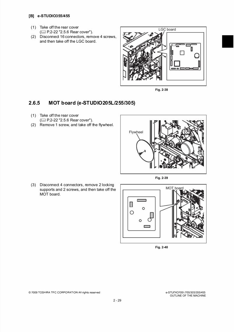
8/17/2019 Toshiba ES455 Service Manual
http://slidepdf.com/reader/full/toshiba-es455-service-manual 57/335
© 2009 TOSHIBA TEC CORPORATION All rights reserved e-STUDIO205L/255/305/355/455OUTLINE OF THE MACHINE
2 - 29
[B] e-STUDIO355/455
2.6.5 MOT board (e-STUDIO205L/255/305)
(1) Take off the rear cover
( P.2-22 "2.5.6 Rear cover").
(2) Disconnect 16 connectors, remove 4 screws,
and then take off the LGC board.
Fig. 2-38
(1) Take off the rear cover( P.2-22 "2.5.6 Rear cover").
(2) Remove 1 screw, and take off the flywheel.
Fig. 2-39
(3) Disconnect 4 connectors, remove 2 locking
supports and 2 screws, and then take off the
MOT board.
Fig. 2-40
LGC board
Flywheel
MOT board

8/17/2019 Toshiba ES455 Service Manual
http://slidepdf.com/reader/full/toshiba-es455-service-manual 58/335
e-STUDIO205L/255/305/355/455 © 2009 TOSHIBA TEC CORPORATION All rights reservedOUTLINE OF THE MACHINE
2 - 30
2.6.6 MOT2 board (e-STUDIO355/455)
2.6.7 Switching regulator Note:
Be very careful of residual charge in the capacitors of the switching regulator; this may remain
even after the main switch is turned OFF.
(1) Take off the rear cover
( P.2-22 "2.5.6 Rear cover").
(2) Remove 1 screw, and take off the flywheel.
Fig. 2-41
(3) Disconnect 9 connectors, remove 4 screws,
and then take off the MOT2 board.
Fig. 2-42
(1) Take off the laser optical unit.
( P.7-7 "7.5.1 Laser optical unit").
(2) Take off the left cover
( P.2-24 "2.5.10 Left cover").
(3) Disconnect 10 connectors, remove 9 screws,
and then take off the Switching regulator.
Note:Be careful not to touch the area covered with
a Mylar since electrical charge may remain.
Fig. 2-43
Flywheel
MOT2 board
Switching regulator
Except for NAD, MJD

8/17/2019 Toshiba ES455 Service Manual
http://slidepdf.com/reader/full/toshiba-es455-service-manual 59/335
© 2009 TOSHIBA TEC CORPORATION All rights reserved e-STUDIO205L/255/305/355/455OUTLINE OF THE MACHINE
2 - 31
2.6.8 High-voltage transformer
(1) Take off the laser optical unit.
( P.7-7 "7.5.1 Laser optical unit").
(2) Take off the left cover
( P.2-24 "2.5.10 Left cover").
(3) Remove 1 screw and take off the duct.
Fig. 2-44
(4)
• e-STUDIO205L/255/305: Disconnect 6
terminals and one connector, remove 2
screws, and then take off the High-
voltage transformer together with itsbracket.
Fig. 2-45
• e-STUDIO355/455: Disconnect 6
terminals and 2 connectors, remove 2
screws, and then take off the High-
voltage transformer together with its
bracket.
Fig. 2-46
Duct
High-voltage transformer
High-voltage transformer

8/17/2019 Toshiba ES455 Service Manual
http://slidepdf.com/reader/full/toshiba-es455-service-manual 60/335
e-STUDIO205L/255/305/355/455 © 2009 TOSHIBA TEC CORPORATION All rights reservedOUTLINE OF THE MACHINE
2 - 32
2.6.9 SRAM board
(5) Remove 5 screws and then take off the
bracket from the High-voltage transformer.
Fig. 2-47
(1) Take off the rear cover
( P.2-22 "2.5.6 Rear cover").
(2) Release 2 latches and take off the SRAM
board for the LGC board with the case.
Fig. 2-48
(3) Release 2 latches and take off the SRAMboard for SYS board from the case.
Fig. 2-49
High-voltage transformer
Bracket Bracket
Latch
Latch
Case
Latch SRAM board
Case

8/17/2019 Toshiba ES455 Service Manual
http://slidepdf.com/reader/full/toshiba-es455-service-manual 61/335
© 2009 TOSHIBA TEC CORPORATION All rights reserved e-STUDIO205L/255/305/355/455OUTLINE OF THE MACHINE
2 - 33
2.7 Installation and Replacement of Options
Important:• Be sure to turn the power OFF and unplug the power cable before installing and removing of
options.
2.7.1 MR-3021/MR3022 (Reversing Automatic Document Feeder
(RADF))
(1) Turn the power OFF and unplug the power
cable.
(2) Remove 1 screw and take off the connector
cover.
Fig. 2-50
(3) Disconnect the connector.
Fig. 2-51
(4) Remove 2 screws and take off the bracket on
the rear side.
Fig. 2-52
Connector cover
Connector
Bracket

8/17/2019 Toshiba ES455 Service Manual
http://slidepdf.com/reader/full/toshiba-es455-service-manual 62/335
e-STUDIO205L/255/305/355/455 © 2009 TOSHIBA TEC CORPORATION All rights reservedOUTLINE OF THE MACHINE
2 - 34
(5) Remove 1 screw and 1 washer on the rear
side.
Fig. 2-53
(6) Remove 1 screw on the rear side.
Fig. 2-54
(7) Open the RADF.
Fig. 2-55

8/17/2019 Toshiba ES455 Service Manual
http://slidepdf.com/reader/full/toshiba-es455-service-manual 63/335
© 2009 TOSHIBA TEC CORPORATION All rights reserved e-STUDIO205L/255/305/355/455OUTLINE OF THE MACHINE
2 - 35
2.7.2 KD-1025 (Paper Feed Pedestal (PFP))
(8) Remove 2 screws on the front side.
Fig. 2-56
(9) Slide the RADF backward and take it off by
lifting it up.
Fig. 2-57
(1) Turn the power OFF and unplug the powercable.
(2) Remove 1 screw and take off the connector
cover.
Fig. 2-58
Connector cover

8/17/2019 Toshiba ES455 Service Manual
http://slidepdf.com/reader/full/toshiba-es455-service-manual 64/335
e-STUDIO205L/255/305/355/455 © 2009 TOSHIBA TEC CORPORATION All rights reservedOUTLINE OF THE MACHINE
2 - 36
(3) Remove 1 screw and the ground wire, and
then disconnect 2 connectors (3 connectors
if the optional damp heater is installed).
Fig. 2-59
(4) Remove 1 screw each from the lower drawer
of the equipment and the PFP upper drawer.
Then take off the stoppers.
(5) Take off the lower drawer of the equipment
and PFP upper drawer.
Fig. 2-60
(6) Remove 3 screws and take off 2 fixing
brackets on the rear side.
Fig. 2-61
Drawer
Fixing bracket
Fixing bracket

8/17/2019 Toshiba ES455 Service Manual
http://slidepdf.com/reader/full/toshiba-es455-service-manual 65/335
© 2009 TOSHIBA TEC CORPORATION All rights reserved e-STUDIO205L/255/305/355/455OUTLINE OF THE MACHINE
2 - 37
2.7.3 KD-1026 (Large Capacity Feeder (LCF))
(7) Remove 3 screws and take off 2 fixing
brackets on the front side.
Fig. 2-62
(8) Lift up the equipment and take off the PFP.
Fig. 2-63
(1) Turn the power OFF and unplug the powercable.
(2) Remove 1 screw and take off the connector
cover.
Fig. 2-64
Fixing bracket Fixing bracket
Connector cover
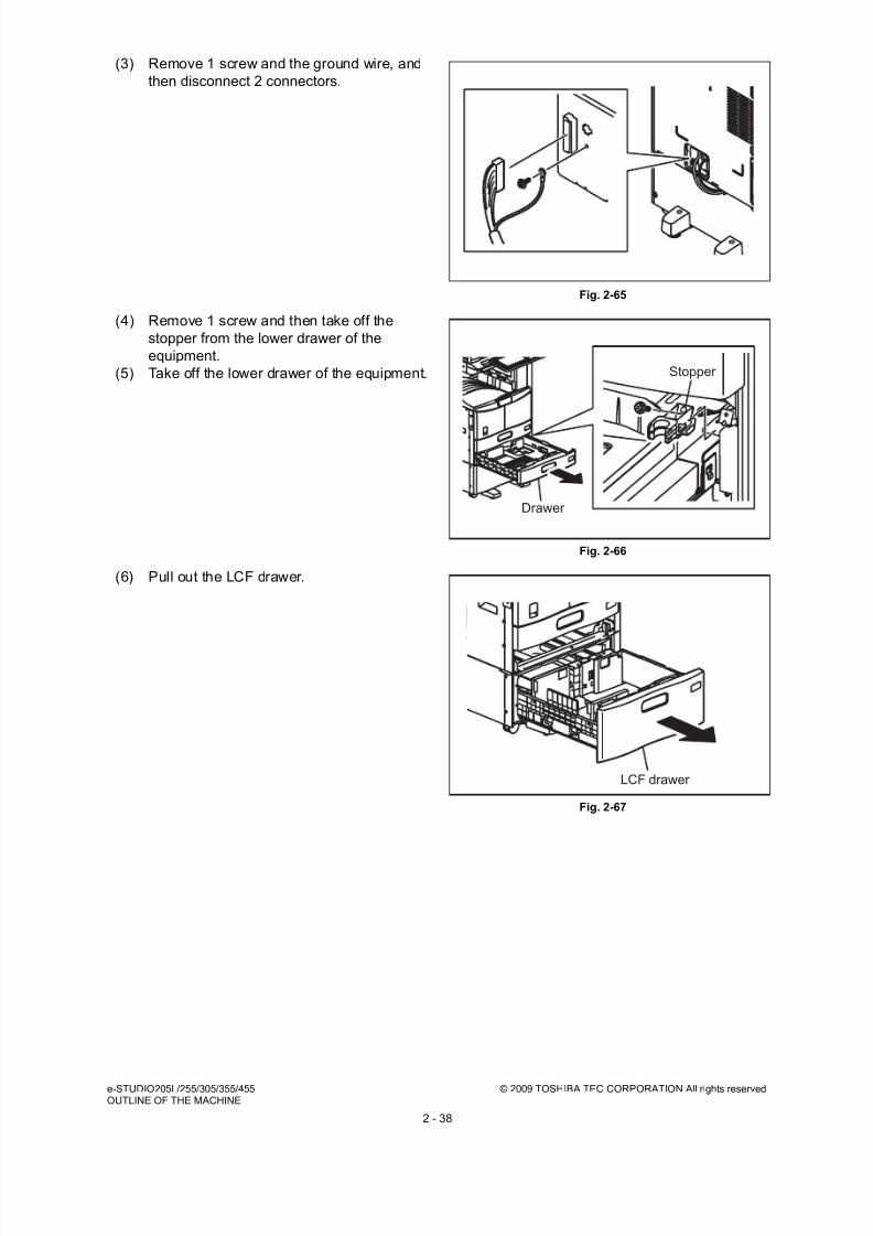
8/17/2019 Toshiba ES455 Service Manual
http://slidepdf.com/reader/full/toshiba-es455-service-manual 66/335
e-STUDIO205L/255/305/355/455 © 2009 TOSHIBA TEC CORPORATION All rights reservedOUTLINE OF THE MACHINE
2 - 38
(3) Remove 1 screw and the ground wire, and
then disconnect 2 connectors.
Fig. 2-65
(4) Remove 1 screw and then take off the
stopper from the lower drawer of the
equipment.
(5) Take off the lower drawer of the equipment.
Fig. 2-66
(6) Pull out the LCF drawer.
Fig. 2-67
Drawer
Stopper
LCF drawer

8/17/2019 Toshiba ES455 Service Manual
http://slidepdf.com/reader/full/toshiba-es455-service-manual 67/335
© 2009 TOSHIBA TEC CORPORATION All rights reserved e-STUDIO205L/255/305/355/455OUTLINE OF THE MACHINE
2 - 39
(7) Remove 3 screws and take off 2 fixing
brackets on the rear side.
Fig. 2-68
(8) Remove 3 screws and take off 2 fixing
brackets on the front side.
Fig. 2-69
(9) Lift up the equipment and take off the LCF.
Fig. 2-70
Fixing bracket
Fixing bracket
Fixing bracketFixing bracket
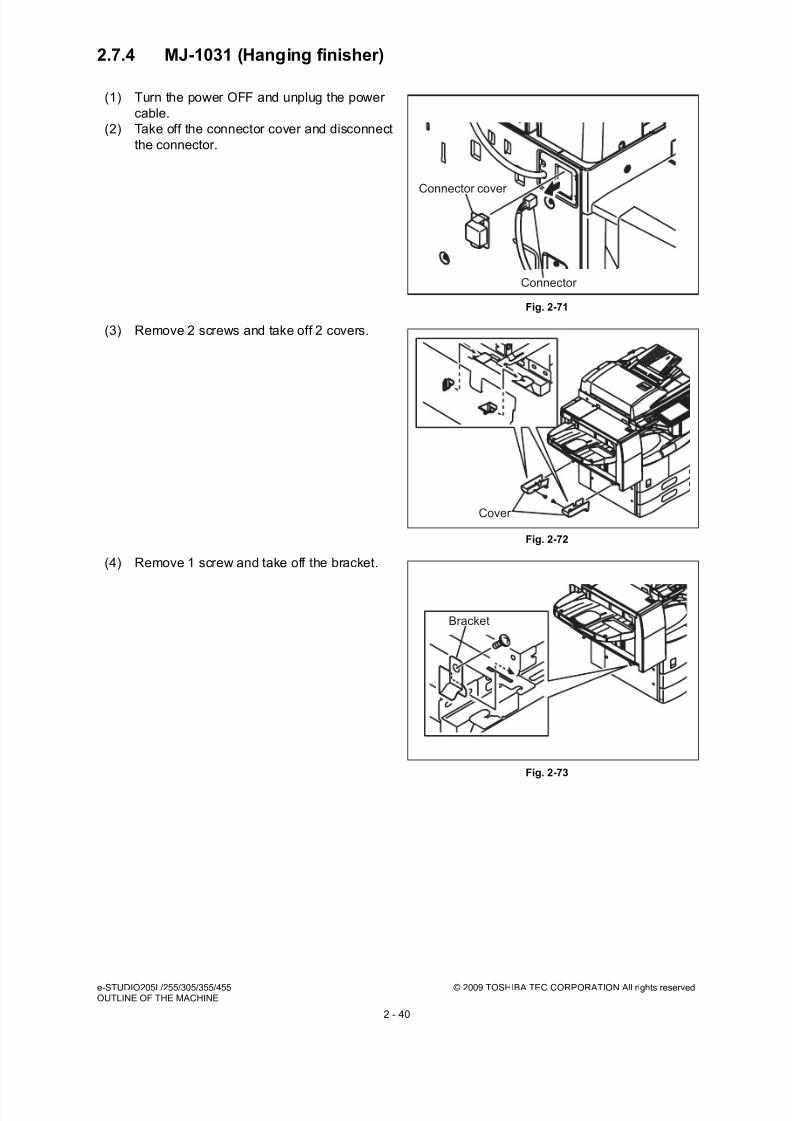
8/17/2019 Toshiba ES455 Service Manual
http://slidepdf.com/reader/full/toshiba-es455-service-manual 68/335
e-STUDIO205L/255/305/355/455 © 2009 TOSHIBA TEC CORPORATION All rights reservedOUTLINE OF THE MACHINE
2 - 40
2.7.4 MJ-1031 (Hanging finisher)
(1) Turn the power OFF and unplug the power
cable.
(2) Take off the connector cover and disconnect
the connector.
Fig. 2-71
(3) Remove 2 screws and take off 2 covers.
Fig. 2-72
(4) Remove 1 screw and take off the bracket.
Fig. 2-73
Connector
Connector cover
Cover
Bracket
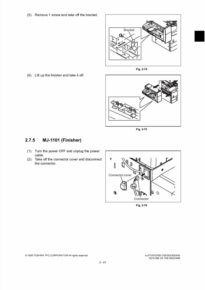
8/17/2019 Toshiba ES455 Service Manual
http://slidepdf.com/reader/full/toshiba-es455-service-manual 69/335
© 2009 TOSHIBA TEC CORPORATION All rights reserved e-STUDIO205L/255/305/355/455OUTLINE OF THE MACHINE
2 - 41
2.7.5 MJ-1101 (Finisher)
(5) Remove 1 screw and take off the bracket.
Fig. 2-74
(6) Lift up the finisher and take it off.
Fig. 2-75
(1) Turn the power OFF and unplug the powercable.
(2) Take off the connector cover and disconnect
the connector.
Fig. 2-76
Bracket
Connector cover
Connector

8/17/2019 Toshiba ES455 Service Manual
http://slidepdf.com/reader/full/toshiba-es455-service-manual 70/335
e-STUDIO205L/255/305/355/455 © 2009 TOSHIBA TEC CORPORATION All rights reservedOUTLINE OF THE MACHINE
2 - 42
2.7.6 MJ-1024 (Saddle stitch finisher)
(3) Open the front cover of the finisher.
(4) Remove 1 screw and take off the bracket.
Fig. 2-77
(5) Hold down the fixing lever of the finisher.
Then take off the Finisher.
Note:Be careful not to fell the finisher when
moving the finisher unit only.
Fig. 2-78
(1) Turn the power OFF and unplug the powercable.
(2) Take off the connector cover and disconnect
the connector.
Fig. 2-79
Bracket
Lever
Connector
Connector cover
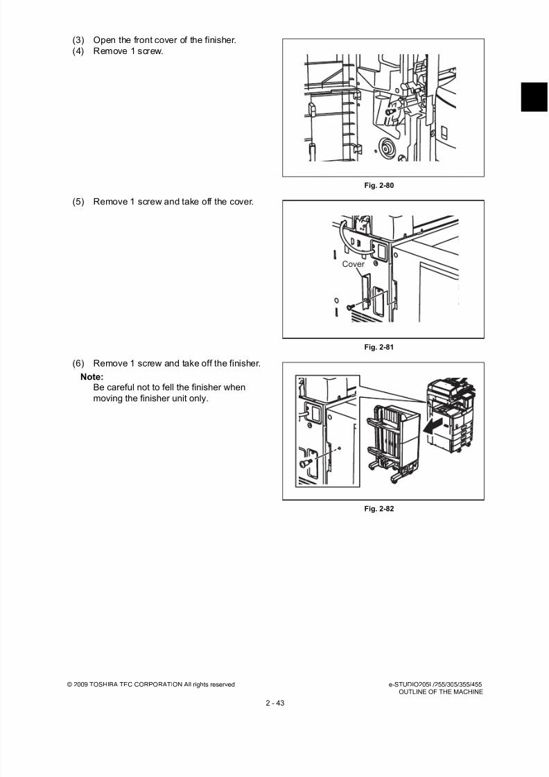
8/17/2019 Toshiba ES455 Service Manual
http://slidepdf.com/reader/full/toshiba-es455-service-manual 71/335
© 2009 TOSHIBA TEC CORPORATION All rights reserved e-STUDIO205L/255/305/355/455OUTLINE OF THE MACHINE
2 - 43
(3) Open the front cover of the finisher.
(4) Remove 1 screw.
Fig. 2-80
(5) Remove 1 screw and take off the cover.
Fig. 2-81
(6) Remove 1 screw and take off the finisher.
Note:Be careful not to fell the finisher when
moving the finisher unit only.
Fig. 2-82
Cover

8/17/2019 Toshiba ES455 Service Manual
http://slidepdf.com/reader/full/toshiba-es455-service-manual 72/335
e-STUDIO205L/255/305/355/455 © 2009 TOSHIBA TEC CORPORATION All rights reservedOUTLINE OF THE MACHINE
2 - 44
2.7.7 MJ-1025 (Saddle stitch finisher)
(1) Turn the power OFF and unplug the power
cable.
(2) Take off the connector cover and disconnect
the connector.
Fig. 2-83
(3) Pull out the finisher while pushing the lever.
Fig. 2-84
(4) Remove 1 screw and take off the finisher
from the rail.
Note:Be careful not to fell the finisher when
moving the finisher unit only.
Fig. 2-85
Connector cover
Connector
Lever
Rail
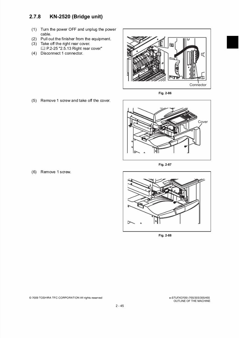
8/17/2019 Toshiba ES455 Service Manual
http://slidepdf.com/reader/full/toshiba-es455-service-manual 73/335
© 2009 TOSHIBA TEC CORPORATION All rights reserved e-STUDIO205L/255/305/355/455OUTLINE OF THE MACHINE
2 - 45
2.7.8 KN-2520 (Bridge unit)
(1) Turn the power OFF and unplug the power
cable.
(2) Pull out the finisher from the equipment.
(3) Take off the right rear cover.
P.2-25 "2.5.13 Right rear cover"
(4) Disconnect 1 connector.
Fig. 2-86
(5) Remove 1 screw and take off the cover.
Fig. 2-87
(6) Remove 1 screw.
Fig. 2-88
Connector
Cover
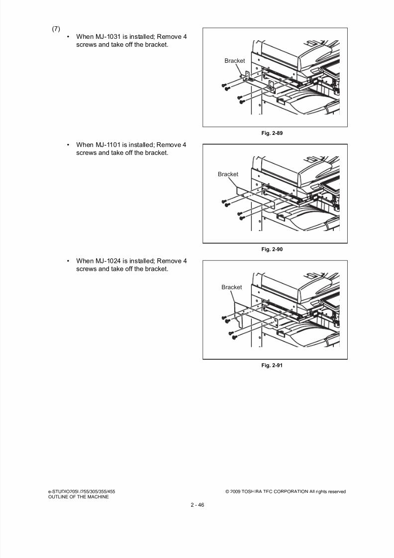
8/17/2019 Toshiba ES455 Service Manual
http://slidepdf.com/reader/full/toshiba-es455-service-manual 74/335
e-STUDIO205L/255/305/355/455 © 2009 TOSHIBA TEC CORPORATION All rights reservedOUTLINE OF THE MACHINE
2 - 46
(7)
• When MJ-1031 is installed; Remove 4
screws and take off the bracket.
Fig. 2-89
• When MJ-1101 is installed; Remove 4
screws and take off the bracket.
Fig. 2-90
• When MJ-1024 is installed; Remove 4
screws and take off the bracket.
Fig. 2-91
Bracket
Bracket
Bracket

8/17/2019 Toshiba ES455 Service Manual
http://slidepdf.com/reader/full/toshiba-es455-service-manual 75/335
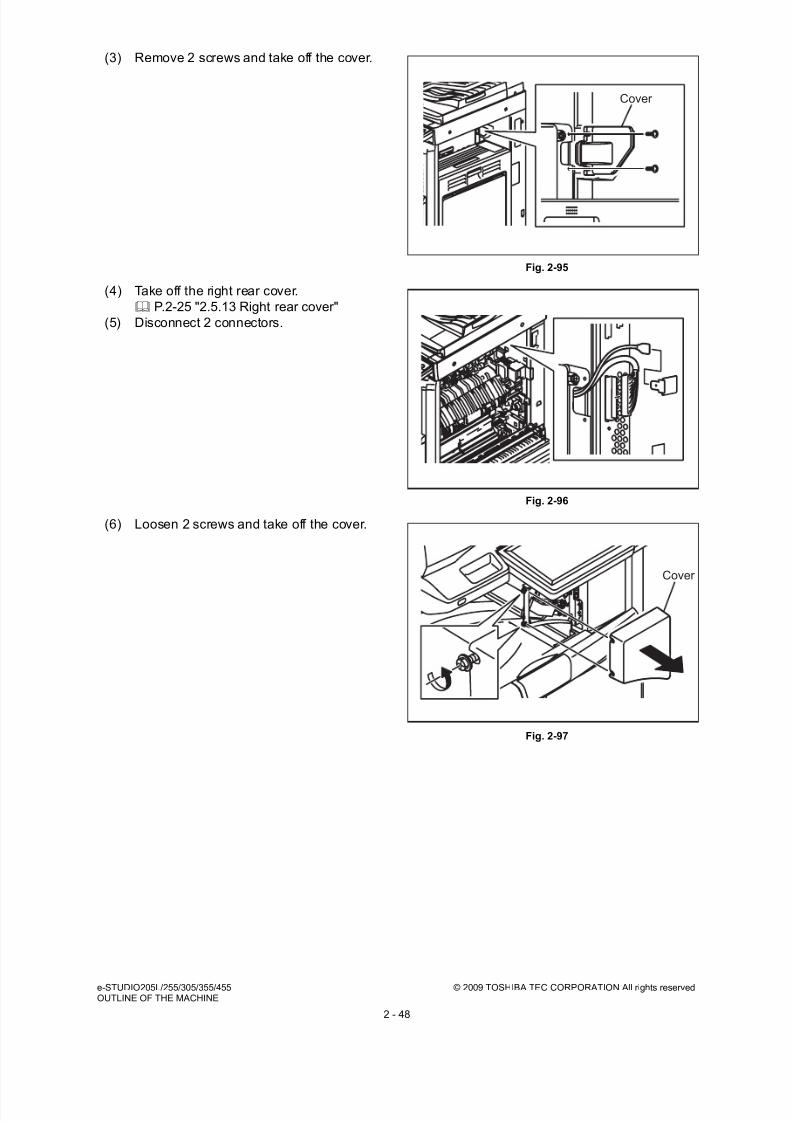
8/17/2019 Toshiba ES455 Service Manual
http://slidepdf.com/reader/full/toshiba-es455-service-manual 76/335
e-STUDIO205L/255/305/355/455 © 2009 TOSHIBA TEC CORPORATION All rights reservedOUTLINE OF THE MACHINE
2 - 48
(3) Remove 2 screws and take off the cover.
Fig. 2-95
(4) Take off the right rear cover.
P.2-25 "2.5.13 Right rear cover"
(5) Disconnect 2 connectors.
Fig. 2-96
(6) Loosen 2 screws and take off the cover.
Fig. 2-97
Cover
Cover

8/17/2019 Toshiba ES455 Service Manual
http://slidepdf.com/reader/full/toshiba-es455-service-manual 77/335
© 2009 TOSHIBA TEC CORPORATION All rights reserved e-STUDIO205L/255/305/355/455OUTLINE OF THE MACHINE
2 - 49
2.7.10 MJ-5005 (Offset tray) (e-STUDIO205L/255/305)
(7) Remove 1 screw. Lift up the job separator
and release the hook. Take off the job
separator toward the front.
Fig. 2-98
(1) Turn the power OFF and unplug the power
cable.
(2) Take off the tray.
Fig. 2-99
(3) Remove 2 screws and take off the cover.
Fig. 2-100
Tray
Cover
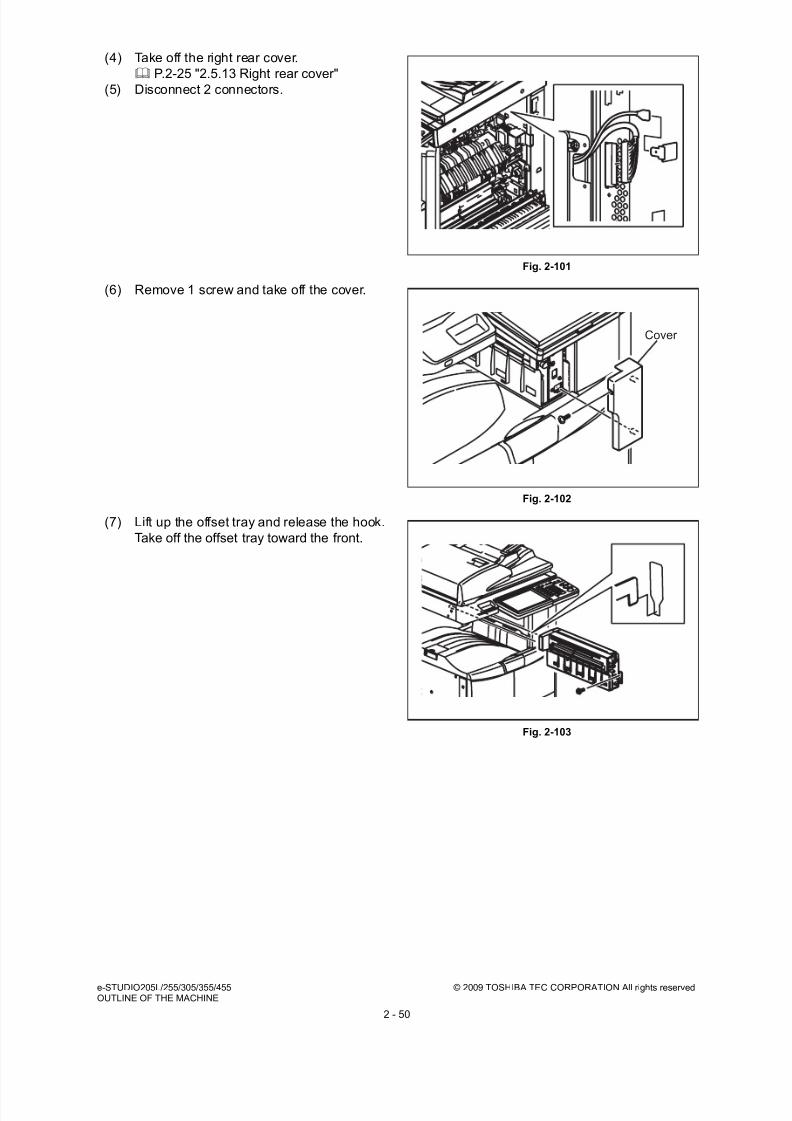
8/17/2019 Toshiba ES455 Service Manual
http://slidepdf.com/reader/full/toshiba-es455-service-manual 78/335
e-STUDIO205L/255/305/355/455 © 2009 TOSHIBA TEC CORPORATION All rights reservedOUTLINE OF THE MACHINE
2 - 50
(4) Take off the right rear cover.
P.2-25 "2.5.13 Right rear cover"
(5) Disconnect 2 connectors.
Fig. 2-101
(6) Remove 1 screw and take off the cover.
Fig. 2-102
(7) Lift up the offset tray and release the hook.
Take off the offset tray toward the front.
Fig. 2-103
Cover

8/17/2019 Toshiba ES455 Service Manual
http://slidepdf.com/reader/full/toshiba-es455-service-manual 79/335
© 2009 TOSHIBA TEC CORPORATION All rights reserved e-STUDIO205L/255/305/355/455OUTLINE OF THE MACHINE
2 - 51
2.7.11 MJ-5006 (Job separator) (e-STUDIO355/455)
(1) Turn the power OFF and unplug the power
cable.
(2) Take off the tray.
Fig. 2-104
(3) Remove 2 screws and take off the cover.
Fig. 2-105
(4) Take off the right rear cover.
P.2-25 "2.5.13 Right rear cover"
(5) Disconnect 2 connectors.
Fig. 2-106
Tray
Cover

8/17/2019 Toshiba ES455 Service Manual
http://slidepdf.com/reader/full/toshiba-es455-service-manual 80/335
e-STUDIO205L/255/305/355/455 © 2009 TOSHIBA TEC CORPORATION All rights reservedOUTLINE OF THE MACHINE
2 - 52
(6) Remove 2 screws and take off the cover.
Fig. 2-107
Cover

8/17/2019 Toshiba ES455 Service Manual
http://slidepdf.com/reader/full/toshiba-es455-service-manual 81/335
© 2009 TOSHIBA TEC CORPORATION All rights reserved e-STUDIO205L/255/305/355/455OUTLINE OF THE MACHINE
2 - 53
2.8 Damp Heater Kit (MF-4550U/E) Installation Procedure
2.8.1 Preparation
Damp Heater Kit (check if all of the following parts are in it), tools
Notes:1. When installing the Damp Heater, ensure sufficient work space for disassembling the
equipment.
2. Turn the power of the equipment OFF and unplug the power cable before the installation.
3. Take off the Finisher (optional), the FAX unit, the Job separator (optional), Offset tray
(optional), or the Hole Punch Unit (optional) before starting the installation, if installed.
4. Be sure not to drop small parts such as screws into the equipment.
2.8.2 Procedure
(a) Scanner Damp Heater (Left)
(b) Scanner Damp Heater (Right)
(c) Drum Damp Heater
(d) Fuse board
(e) Fixing screw (for the scanner (Left))
(f) Fixing screw (for the scanner (right), fuse
board, drum)
(g) Clamp (for the scanner (Left))
(h) Harness (for the scanner and drum)
(i) Harness (for the fuse board)
(j) Harness (for the scanner (right))
(k) Harness (for the fuse board and the
switching regulator join)
Fig. 2-108
(1) Remove 3 screws and take off the right
upper cover.
Fig. 2-109
(f)(e)
(f)
(i)
(k)
(j)
(a) (b)
(h)
(g)
(c)
10
5 12
27 27
39,40 37,38 34,3540
10,1129
6,7
(d)(f)
5
Right upper cover

8/17/2019 Toshiba ES455 Service Manual
http://slidepdf.com/reader/full/toshiba-es455-service-manual 82/335
e-STUDIO205L/255/305/355/455 © 2009 TOSHIBA TEC CORPORATION All rights reservedOUTLINE OF THE MACHINE
2 - 54
(2) Remove 2 screws and take off the fixing
bracket.
Fig. 2-110
(3) Take off the original glass.
Fig. 2-111
(4) Remove 4 screws and take off the lens
cover.
Fig. 2-112
Fixing bracket
Original glass
Lens cover

8/17/2019 Toshiba ES455 Service Manual
http://slidepdf.com/reader/full/toshiba-es455-service-manual 83/335
© 2009 TOSHIBA TEC CORPORATION All rights reserved e-STUDIO205L/255/305/355/455OUTLINE OF THE MACHINE
2 - 55
(5) Install the Scanner Damp Heater (Right) on
the lens cover with 2 screws.
Fig. 2-113
(6) Connect the connector of the harness and
install the clamp to the lens unit.
(7) Insert the connector into the lens unit.
Fig. 2-114
(8) Install the lens cover with 4 screws.
Fig. 2-115
Scanner Damp
Heater (Right)
Lens cover

8/17/2019 Toshiba ES455 Service Manual
http://slidepdf.com/reader/full/toshiba-es455-service-manual 84/335
e-STUDIO205L/255/305/355/455 © 2009 TOSHIBA TEC CORPORATION All rights reservedOUTLINE OF THE MACHINE
2 - 56
(9) Rotate the pulley to move the carriage to the
paper exit side.
Fig. 2-116
(10) Install the Scanner Damp Heater (Left) with 2
screws.
Fig. 2-117
(11) Install the Scanner Damp Heater (Left) in the
cutout of the frame in the equipment as
shown in the right-hand figure.Fix the Scanner Damp Heater (Left) with 1
screw and then insert 1 connectors.
Note:Check that no harnesses will be caught by
moving the carriage.
Fig. 2-118
Carriage
Scanner Damp
Heater (Left)

8/17/2019 Toshiba ES455 Service Manual
http://slidepdf.com/reader/full/toshiba-es455-service-manual 85/335
© 2009 TOSHIBA TEC CORPORATION All rights reserved e-STUDIO205L/255/305/355/455OUTLINE OF THE MACHINE
2 - 57
(12) Attach the harness to 1 connector and then
install the clamp in the equipment.
(13) Fix the harness with 2 clamps.
Fig. 2-119
(14) Install the original glass.
Note:When installing, fit 2 small protrusions of the
original glass in the groove of the equipment
and fix the original glass with the fixing
bracket by pushing it to the left rear direction.
Fig. 2-120
(15) Install the fixing bracket with 2 screws.
Fig. 2-121
2
1
Original glass
Fixing bracket
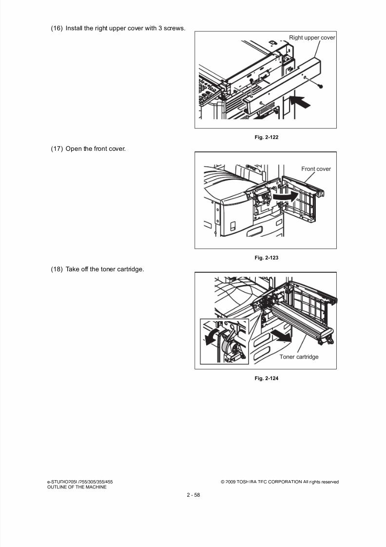
8/17/2019 Toshiba ES455 Service Manual
http://slidepdf.com/reader/full/toshiba-es455-service-manual 86/335
e-STUDIO205L/255/305/355/455 © 2009 TOSHIBA TEC CORPORATION All rights reservedOUTLINE OF THE MACHINE
2 - 58
(16) Install the right upper cover with 3 screws.
Fig. 2-122
(17) Open the front cover.
Fig. 2-123
(18) Take off the toner cartridge.
Fig. 2-124
Right upper cover
Front cover
Toner cartridge

8/17/2019 Toshiba ES455 Service Manual
http://slidepdf.com/reader/full/toshiba-es455-service-manual 87/335
© 2009 TOSHIBA TEC CORPORATION All rights reserved e-STUDIO205L/255/305/355/455OUTLINE OF THE MACHINE
2 - 59
(19) Open the automatic duplexing unit.
Fig. 2-125
(20) Loosen 2 screws and pull out the process
unit.
Fig. 2-126
(21) Remove 2 screws, and then take off the
inner tray.
Fig. 2-127
Automatic duplexing unit
Process unit
Inner tray

8/17/2019 Toshiba ES455 Service Manual
http://slidepdf.com/reader/full/toshiba-es455-service-manual 88/335
e-STUDIO205L/255/305/355/455 © 2009 TOSHIBA TEC CORPORATION All rights reservedOUTLINE OF THE MACHINE
2 - 60
(22) Remove 1 screw and disconnect 1
connector. Take off the duct.
Fig. 2-128
(23) Remove 1 screw and then take off the Damp
Heater cover.
Fig. 2-129
(24) Remove 5 screws. Lift up the rear cover and
then release 3 hooks on the upper side.
Then open the upper side of the rear coverslightly toward you, and then take off the rear
cover by lifting it up.
Fig. 2-130
Duct
Screw
Damp Heater cover
Rear cover

8/17/2019 Toshiba ES455 Service Manual
http://slidepdf.com/reader/full/toshiba-es455-service-manual 89/335
© 2009 TOSHIBA TEC CORPORATION All rights reserved e-STUDIO205L/255/305/355/455OUTLINE OF THE MACHINE
2 - 61
(25) Disconnect 2 connectors from the LGC
board.
Fig. 2-131
(26) Remove 1 screw and take off the laser
optical unit.
Note:When removing and installing the laser
optical unit, be careful not to deform the leaf
spring.
Fig. 2-132
(27) Fix the fuse board with 2 screws.
Fig. 2-133
Connector
LGC board
Laser optical unit
Leaf spring
Fuse board

8/17/2019 Toshiba ES455 Service Manual
http://slidepdf.com/reader/full/toshiba-es455-service-manual 90/335
e-STUDIO205L/255/305/355/455 © 2009 TOSHIBA TEC CORPORATION All rights reservedOUTLINE OF THE MACHINE
2 - 62
(28) Attach the harness to the connector of the
fuse board.
Fig. 2-134
(29) Run the harness through the clamp, and
then through the hole of the frame of the
equipment.
Fig. 2-135
(30) Run the harness through the clamp. Then
run it through the hole in the equipment and
wire it to the front side as shown in the right-hand figure.
Fig. 2-136
Fuse board

8/17/2019 Toshiba ES455 Service Manual
http://slidepdf.com/reader/full/toshiba-es455-service-manual 91/335
© 2009 TOSHIBA TEC CORPORATION All rights reserved e-STUDIO205L/255/305/355/455OUTLINE OF THE MACHINE
2 - 63
(31) Connect 1 connector and install 3 clamps.
Fig. 2-137
(32) Remove 1 screw and take off the duct.
Fig. 2-138
(33) Fix the harness with 1 clamp, and then insert
the connector into the hole of the frame of
the equipment.
Fig. 2-139
Duct

8/17/2019 Toshiba ES455 Service Manual
http://slidepdf.com/reader/full/toshiba-es455-service-manual 92/335
e-STUDIO205L/255/305/355/455 © 2009 TOSHIBA TEC CORPORATION All rights reservedOUTLINE OF THE MACHINE
2 - 64
(34) Attach the harness to the connector of the
switching regulator.
(35) Run the harness through the hole of the
frame of the equipment, and then wire it to
the rear side.
Fig. 2-140
(36) Attach the harness to the clamp.
Fig. 2-141
(37) Attach the harness to the connector of the
fuse board and the one of the frame of the
equipment.(38) Connect the harness coming from the clamp
to the connector.
Fig. 2-142
Switching regulator
Clamp
Fuse board

8/17/2019 Toshiba ES455 Service Manual
http://slidepdf.com/reader/full/toshiba-es455-service-manual 93/335
© 2009 TOSHIBA TEC CORPORATION All rights reserved e-STUDIO205L/255/305/355/455OUTLINE OF THE MACHINE
2 - 65
(39) Apply 1 hook to the frame of the equipment.
(40) Attach the harness to the connector, and
then fix the Drum Damp Heater with 1 screw.
Notes:• After the Scanner Damp Heater (Left),
Scanner Damp Heater (Right) and Drum
Damp Heater have been installed,
perform the installation following the
opposite procedure of the disassembly.
• Check the following after the installation
of the Damp Heater
1. Image quality
2. Abnormal heating
3. Any screws not installedFig. 2-143

8/17/2019 Toshiba ES455 Service Manual
http://slidepdf.com/reader/full/toshiba-es455-service-manual 94/335
e-STUDIO205L/255/305/355/455 © 2009 TOSHIBA TEC CORPORATION All rights reservedOUTLINE OF THE MACHINE
2 - 66

8/17/2019 Toshiba ES455 Service Manual
http://slidepdf.com/reader/full/toshiba-es455-service-manual 95/335
© 2009 TOSHIBA TEC CORPORATION All rights reserved e-STUDIO205L/255/305/355/455COPY PROCESS
3 - 1
3. COPY PROCESS
3.1 General Description of Copying Process
Fig. 3-1
(1) Charging: Applies negative charge on the
surface of the photoconductive drum.
(7) Transfer: Transfers the visible toner image
on the photoconductive drum onto paper.
(2) Original exposure: Converts images on the
original into optical signals.
(8) Separation: Separates paper with the toner
image from the photoconductive drum.
(3) Data reading: The optical signals are
converted into electrical signals.
(9) Fusing: Fuses the toner image onto the
paper by applying heat and pressure.
(4) Data writing: The electrical signals areconverted into light signal (laser emission)
which exposes the surface of the
photoconductive drum.
(10) Cleaning: Scrapes off the residual tonerfrom the drum.
(5) Development: Negatively-charged toner
adheres to the photoconductive drum and
forms visible image.
(11) Discharging: Eliminates the residual
negative charge from the surface of the
photoconductive drum.
(6) Transfer assist bias: Improves transfer
efficiency.
Original exposure
Xenon lamp19.2 W
Data reading(scanning)
CCD
600 dpi,7450 pixel
Image processing
Discharging
Discharge LED (red)
Wavelength 650nm
e-STUDIO205L/255/305 :
10pcs
e-STUDIO355/455 :
14pcs
(11)
(8)
(7)
(6)
(10)
(2)
(3)
(1)
(4)
(5)
Data writing
Semiconductive laser
Pw=
e-STUDIO205L/255/305 :
4nJ/mm2
e-STUDIO355/455 :
4.5nJ/mm2
Charging
e-STUDIO205L/255/305 :
-502V
e-STUDIO355/455 : -516V
(grid voltage)
Development
Magnetic roller
Bias
e-STUDIO205L/255/305 :
-377VDC+AC
e-STUDIO355/455 :
-377VDC+AC
Toner
Carrier
Cleaning
Blade method
Bypass feeding(100 sheets)
PFP (upper/lower )(550 sheets) or
LCF(200 sheets
)
Drawer feeding(upper/lower )(550 sheets)
Separation
e-STUDIO205L/255/305 :
H -4µADC
C -2.5µADC
L -2.5µADC
e-STUDIO355/455 :
H -4µADC
C -2.5µADC
L -2.5µADC
Transfer assist bias
Fuser pressure roller
+250V
Registration roller
+250V
(9)
Paper exit
Fusing
Lamp heating method
e-STUDIO205L/255/305:
600W x 2
e-STUDIO355/455:
600W x 2 + 300W x 1
Transfer
e-STUDIO205L/255/305 :
H +16µADC
C +16µADC
L +12µADC
e-STUDIO355/455 :
H +23µADC
C +23µADC
L +18µADC

8/17/2019 Toshiba ES455 Service Manual
http://slidepdf.com/reader/full/toshiba-es455-service-manual 96/335
e-STUDIO205L/255/305/355/455 © 2009 TOSHIBA TEC CORPORATION All rights reservedCOPY PROCESS
3 - 2
3.2 Details of Copying Process1. Photoconductive drum
The photoconductive drum consists of two layers.The outer layer is a photoconductive layer made of
an organic photoconductive carrier (OPC), and the inner layer is an aluminum conductive base in a
cylindrical form. The photoconductor has the following property: when it is exposed to light, the
electrical resistance it possesses increases or decreases according to the strength of the light.
Example:
- Strong light
Resistance is decreased (works as a conductor.)- Weak light
Resistance is increased (works as an insulator.)
Fig. 3-2
[Formation of electrostatic latent image]
In the processes of charging, data reading, data writing, discharging described later, negative
potential of the areas on the drum corresponding to black areas of the original are eliminated, while
the areas on the drum corresponding to white areas retains the negative charge.
As this image on the drum formed by the negative potential is not visible, it is called an “electrostatic
latent image.”
Fig. 3-3
Photoconductive layer
Base
Structure of the photoconductive drum(Example of OPC)
0
Time (t)
Black area of original
White area of original
S u r f a c e p o
t e n t i a l ( V )
Dischargeprocess
Chargingprocess
Electric potential of the photoconductive drum
-500

8/17/2019 Toshiba ES455 Service Manual
http://slidepdf.com/reader/full/toshiba-es455-service-manual 97/335

8/17/2019 Toshiba ES455 Service Manual
http://slidepdf.com/reader/full/toshiba-es455-service-manual 98/335
e-STUDIO205L/255/305/355/455 © 2009 TOSHIBA TEC CORPORATION All rights reservedCOPY PROCESS
3 - 4
4. Data writing
Data writing is the process of converting the image signals sent from the image processing section
into optical signal and exposing the drum surface with the light.
Semiconductive laser element converts image signals transmitted from the image processing
section into optical signal (laser emission) to expose the drum surface and form an electrostatic
latent image on it.
Fig. 3-7
Semiconductive
laser element
Polygonal mirror
Photo-
conductive
drum
Imageprocessing
section
LDR board
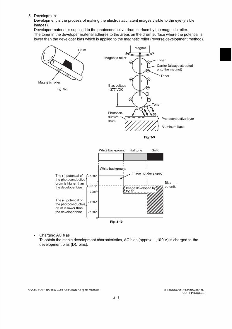
8/17/2019 Toshiba ES455 Service Manual
http://slidepdf.com/reader/full/toshiba-es455-service-manual 99/335
© 2009 TOSHIBA TEC CORPORATION All rights reserved e-STUDIO205L/255/305/355/455COPY PROCESS
3 - 5
5. Development
Development is the process of making the electrostatic latent images visible to the eye (visible
images).
Developer material is supplied to the photoconductive drum surface by the magnetic roller.
The toner in the developer material adheres to the areas on the drum surface where the potential is
lower than the developer bias which is applied to the magnetic roller (reverse development method).
Fig. 3-10
- Charging AC bias
To obtain the stable development characteristics, AC bias (approx. 1,100 V) is charged to the
development bias (DC bias).
Fig. 3-8
Fig. 3-9
Drum
Magnetic roller
Photoconductive layer
Magnet
Magnetic roller
Photocon-
ductive
drum
Aluminum base
Toner
Carrier (always attractedonto the magnet)
Toner
Bias voltage
- 377 VDC
Toner
The (-) potential of the photoconductivedrum is higher thanthe developer bias.
The (-) potential of the photoconductivedrum is lower thanthe developer bias.
0
- 100V
- 200V
- 300V
White background Halftone Solid
White background
Image not developed
Biaspotential
- 508V
- 377VImage developed bytoner

8/17/2019 Toshiba ES455 Service Manual
http://slidepdf.com/reader/full/toshiba-es455-service-manual 100/335
e-STUDIO205L/255/305/355/455 © 2009 TOSHIBA TEC CORPORATION All rights reservedCOPY PROCESS
3 - 6
- Developer material
The developer material consists of a mixture of the toner and carrier. The toner is charged to the
negative polarity and the carrier to positive polarity due to the friction with each other caused by
mixing.
- Magnetic roller
Magnetic brush development
The south and north poles are arranged inside the magnetic roller as shown in the right figure.
The developer material forms a brush-like fluff which contacts the photoconductive drum surface.
This is caused by the magnetic force lines between the south and north poles.
Fig. 3-13
Toner: Mainly consists of the resin and carbon.
Fig. 3-11
Carrier: Consists of the ferrite and resin coating on
its surface to provide consistent frictional
electrification.
Note:If the developer material is used for a long time (beyond its normallife span), the toner is caked onto the carrier.
The charging performance of the carrier is lowered.Symptom: 1. Image density is lowered.
2. Toner scattering occurs.3. Background fogging occurs.
Solution: Replace the developer material.
Fig. 3-12
Carbon(5-10%)
Resin (90-95%)
[Toner ]
approx.
8.5μm
Ferrite
approx. 44 μm
[Carrier ]
No frictional electrification
occurs on the area where thetoner is caked.
Toner Carrier
NS
S
Magnetic forcelineMagnetic roller
Photoconductivedrum

8/17/2019 Toshiba ES455 Service Manual
http://slidepdf.com/reader/full/toshiba-es455-service-manual 101/335
© 2009 TOSHIBA TEC CORPORATION All rights reserved e-STUDIO205L/255/305/355/455COPY PROCESS
3 - 7
- Additional Explanation
The life of the toner cartridge (number of output pages) varies depending on the following
conditions.
Coverage of originals (printing image ratio of the original size) and density of original background
Size and density of originals
The existence of solid black when making prints (when a book is copied and the original cover is
partially opened)
Temperature and humidity in the room when making prints.
Prints density and image quality mode
As indicated in the figure below, the life of the toner cartridge varies depending on the copy mode
and coverage of originals.
A full block in the figure below denotes approx. 5,000 output pages.
Fig. 3-14
A A B C A
Type of originals
A B C
Block

8/17/2019 Toshiba ES455 Service Manual
http://slidepdf.com/reader/full/toshiba-es455-service-manual 102/335
e-STUDIO205L/255/305/355/455 © 2009 TOSHIBA TEC CORPORATION All rights reservedCOPY PROCESS
3 - 8
6. Transfer
Transfer is a process of transferring the toner image (visible image) formed on the drum surface
onto the paper.
An electric charge applied by the high voltage power supply flows to the transfer roller. Then it flows
to the paper and photo conductor. The toner, which has been developed on the photo conductor, is
transferred to this paper with an electric charge.
Fig. 3-15
Fig. 3-16
- Output is controlled as follows to realizes the desirable transfability.
Since the drum and the transfer roller are always contacted, control the amount of adhering
toner.Output is controlled the optimal cleaning efficiency.
Paper position
against transfer
point
Transfer output
e-STUDIO205L/255/305 e-STUDIO355/455
Leading edge (H) +16µADC +23µADC
Center (C) +16µADC +23µADC
Trailing edge (L) +12µADC +18µADC
DrumPaper
Transfer roll
Direction of transportation
Transfer roller Toner
Drum rotation

8/17/2019 Toshiba ES455 Service Manual
http://slidepdf.com/reader/full/toshiba-es455-service-manual 103/335
© 2009 TOSHIBA TEC CORPORATION All rights reserved e-STUDIO205L/255/305/355/455COPY PROCESS
3 - 9
7. Separation
Separation is the process of separating paper which is temporarily adhering to the drum due to the
static electricity during the transfer process.
- Output is controlled as follows to realizes the desirable separability.
Paper may not be separated from the drum surface because of moisture or malfunction of the
separation output during printing. As the result, the paper enters into the cleaner and causes
jamming. To prevent this, a separation finger is used to forcibly separate the paper which was left
around the drum.
Fig. 3-18
8. Transfer assist biasIn the transfer assist bias processing of this equipment, bias voltage is applied to the registrationroller and fuser pressure roller to prevent the charge produced by the transfer roller from flowinginto the transfer unit transport path through the paper.
Method: Apply negative DC bias to the separation
needle.
The positive charge on the paper is decreased.
The electrostatic adherence force between the
paper and drum becomes weak.
The paper is separated from the drum by its
own stiffness.
Fig. 3-17
Paper position against transfer point
Separation output
e-STUDIO205L/255/
305e-STUDIO355/455
Leading edge (H) -4µADC -4µADC
Center (C) -2.5µADC -3µADC
Trailing edge (L) -2.5µADC -3µADC
Separationneedle
Direction of transportation
Drumrotation
Separation needle
Paper movement
Separation finger
Drum rotation
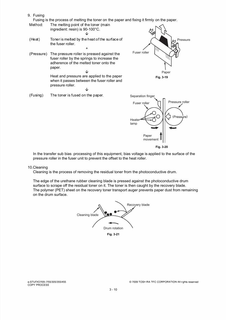
8/17/2019 Toshiba ES455 Service Manual
http://slidepdf.com/reader/full/toshiba-es455-service-manual 104/335
e-STUDIO205L/255/305/355/455 © 2009 TOSHIBA TEC CORPORATION All rights reservedCOPY PROCESS
3 - 10
9. Fusing
Fusing is the process of melting the toner on the paper and fixing it firmly on the paper.
In the transfer sub bias processing of this equipment, bias voltage is applied to the surface of the
pressure roller in the fuser unit to prevent the offset to the heat roller.
10.CleaningCleaning is the process of removing the residual toner from the photoconductive drum.
The edge of the urethane rubber cleaning blade is pressed against the photoconductive drum
surface to scrape off the residual toner on it. The toner is then caught by the recovery blade.
The polymer (PET) sheet on the recovery toner transport auger prevents paper dust from remaining
on the drum surface.
Fig. 3-21
Method: The melting point of the toner (main
ingredient: resin) is 90-100°C.
Fig. 3-19
Fig. 3-20
(Heat) Toner is melted by the heat of the surface of
the fuser roller.
+
(Pressure) The pressure roller is pressed against the
fuser roller by the springs to increase the
adherence of the melted toner onto the
paper.
Heat and pressure are applied to the paper
when it passes between the fuser roller and
pressure roller.
(Fusing) The toner is fused on the paper.
Fuser roller
Paper
Pressure
Pressureressure
Paper movement
Heaterlamp
Fuser roller Pressure roller
Separation finger
(Pressure)
Cleaning blade
Drum rotation
Recovery blade
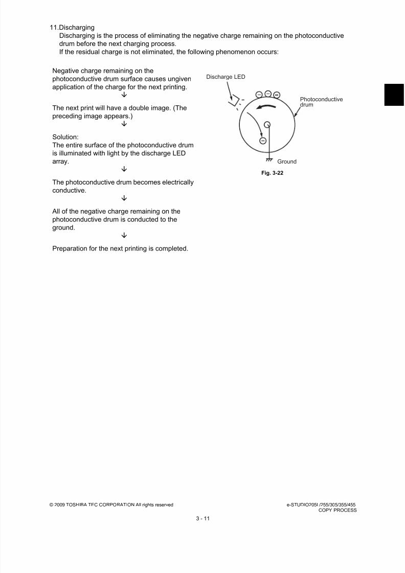
8/17/2019 Toshiba ES455 Service Manual
http://slidepdf.com/reader/full/toshiba-es455-service-manual 105/335
© 2009 TOSHIBA TEC CORPORATION All rights reserved e-STUDIO205L/255/305/355/455COPY PROCESS
3 - 11
11.Discharging
Discharging is the process of eliminating the negative charge remaining on the photoconductive
drum before the next charging process.
If the residual charge is not eliminated, the following phenomenon occurs:
Negative charge remaining on the
photoconductive drum surface causes ungiven
application of the charge for the next printing.
Fig. 3-22
The next print will have a double image. (The
preceding image appears.)
Solution:
The entire surface of the photoconductive drum
is illuminated with light by the discharge LED
array.
The photoconductive drum becomes electrically
conductive.
All of the negative charge remaining on the
photoconductive drum is conducted to the
ground.
Preparation for the next printing is completed.
Discharge LED
Photoconductivedrum
Ground

8/17/2019 Toshiba ES455 Service Manual
http://slidepdf.com/reader/full/toshiba-es455-service-manual 106/335
e-STUDIO205L/255/305/355/455 © 2009 TOSHIBA TEC CORPORATION All rights reservedCOPY PROCESS
3 - 12
3.3 Comparison with e-STUDIO200L/202L/203L/230/230L/232/233/
232S/280/280S/282/283/282S/283S
Process
e-STUDIO200L/202L/203L/230/
230L/232/233/232S/280/280S/
282/283/282S/283S
e-STUDIO205L/255/305/355/455
e-STUDIO205L/255/
305e-STUDIO355/455
1. Photoconductivedrum• Sensitivity• Surface potential
OD-1600 (OPC ø30)
Highly sensitized/durable drum-475 V (Adjustment not required)
OD-4530, OD-4530C(OPC ø30)
-508V (Adjustment notrequired)
2. Charging
• Grid voltage
Scorotron method(Needleelectrode)-495 V(Adjustment not required)
-502 V(Adjustment notrequired)
-516 V(Adjustment notrequired)
3. Data writing• Light source
• Light amount
Semiconductor laser (Adjustmentnot required)
4.0 nJ/mm2
4.5nJ/mm2
4. Development• Magnetic roller • Auto-toner • Toner supply• Toner-empty
detection• Toner
• Developer
material• Developer bias
One magnetic roller Magnetic bridge-circuit methodToner cartridgeDensity detection method
T-2320, T-2320E, T-2320D, T-2320C, T-2320T (e-STUDIO200L/230/230L/280/280S)T-2340, T-2340E, T-2340D, T-2340C, T-2340T (e-STUDIO202L/232/232S/282/282S)T-2840, T-2840E, T-2340C(e-STUDIO203L/233/283/283S)D-2320, D-2320C
DC-357 V Adjustable output(during printing) AC 1100 V (Adjustment notrequired, during printing)DC+150 V Fixed (others)
PS-ZT4530, PS-ZT4530A,PS-ZT4530C, PS-ZT4530D,PS-ZT4530T, PS-ZT4530E,PS-ZT4530C10K
PS-ZD4530, D-4530C
DC-377 V Adjustableoutput AC 1100 V
No reverse bias output
5. Transfer • Transfer method• Transfer output
• Transfer assistbias
Corotron transfer method Adjustable output (Constantcurrent)+600 V
Transfer roller output Adjustable output(Constant current)+250V
6. Separation
• Separationmethod
• Separation output
Corotron separation method(Wireelectrode) Adjustable output (Constantcurrent)
Needle separationmethod Adjustable output(Constant current)
7. Discharge• Discharging
position• Discharge LED
Exposure after cleaning
15 red LED’s
10 red LED’s
14 red LED’s
8. Cleaning• Method• Recovered toner
Cleaning bladeReuse (There is the recoveredtoner supply mechanism.)

8/17/2019 Toshiba ES455 Service Manual
http://slidepdf.com/reader/full/toshiba-es455-service-manual 107/335
© 2009 TOSHIBA TEC CORPORATION All rights reserved e-STUDIO205L/255/305/355/455COPY PROCESS
3 - 13
9. Fusing• Method
• Cleaning
• Heater
Long-life fuser roller method• Fuser roller:
Thin roller coated withfluoroplastic (ø30)
• Pressure roller:PFA tube roller (ø30)
Cleaning roller for pressure roller(ø16)Heater lamp(564W x 2)Turned ON/OFF by thermistor
• Fuser roller:Thin roller coatedwith fluoroplastic(ø35)
• Pressure roller:PFA tube roller (ø30)
(600W x 2)
•
• Pressure roller:PFA tube roller (ø35)
(600W x 2 + 300W x 1)
Process
e-STUDIO200L/202L/203L/230/
230L/232/233/232S/280/280S/
282/283/282S/283S
e-STUDIO205L/255/305/355/455
e-STUDIO205L/255/
305e-STUDIO355/455

8/17/2019 Toshiba ES455 Service Manual
http://slidepdf.com/reader/full/toshiba-es455-service-manual 108/335
e-STUDIO205L/255/305/355/455 © 2009 TOSHIBA TEC CORPORATION All rights reservedCOPY PROCESS
3 - 14

8/17/2019 Toshiba ES455 Service Manual
http://slidepdf.com/reader/full/toshiba-es455-service-manual 109/335
© 2009 TOSHIBA TEC CORPORATION All rights reserved e-STUDIO205L/255/305/355/455GENERAL OPERATION
4 - 1
4. GENERAL OPERATION
4.1 Overview of Operation
Operation of equipment Operation during initializing, pre-running and ready
Copying operation
Drawer feed copying by [START] button
Bypass feed copying
Interrupt copying

8/17/2019 Toshiba ES455 Service Manual
http://slidepdf.com/reader/full/toshiba-es455-service-manual 110/335
e-STUDIO205L/255/305/355/455 © 2009 TOSHIBA TEC CORPORATION All rights reservedGENERAL OPERATION
4 - 2
4.2 Description of Operation
4.2.1 Warming-up
1. Initialization
Power ON
→ Heater lamp ON
→ Set number “1” reproduction ratio “100%” and “WAIT WARMING UP” are displayed
→ Fan motors ON
→ Initialization of scanning system- The carriage moves to the home position.
- The carriage moves to the peak detection position.
- The exposure lamp is turned ON.
- Peak detection (white color is detected by the shading correction plate)
- The exposure lamp is turned OFF.
→ “READY (WARMING UP)” is displayed
2. Pre-running operation
The pre-running operation is started when the temperature of the fuser roller surface reaches a
certain temperature.
→ The main motor is turned ON.
- Fuser roller rotated- Drum rotated
→ Initialization of feeding system
- Each drawer tray goes up.
→ Pre-running operation stops after three seconds.
3. When the surface temperature of the fuser roller becomes sufficient for fusing,
→ “READY” is displayed.
4.2.2 Ready state (ready for copying)
Buttons on the control panel enabled
→ When no button is pressed for a certain period of time,
- Set number “1” and reproduction ratio “100%” are displayed. Equipment returns to the normal
ready state.

8/17/2019 Toshiba ES455 Service Manual
http://slidepdf.com/reader/full/toshiba-es455-service-manual 111/335
© 2009 TOSHIBA TEC CORPORATION All rights reserved e-STUDIO205L/255/305/355/455GENERAL OPERATION
4 - 3
4.2.3 Drawer feed copying (Upper drawer paper feeding)
1. Press the [START] button
→ “READY” changes to “COPYING”
→ Exposure lamp ON
→ Scan motor ON → carriages -1 and -2 move forward
→ Polygonal motor rotates in high speed
→ Main motor and exit motor ON
- The drum, fuser unit, developer unit and exit roller are driven.
2. Drawer paper feeding
→ Main charger, developer bias and discharge LED ON. Fans are rotated in high speed. Drawer
feed clutch ON.
- The pickup roller, feed roller and separation roller start to rotate.
→ Paper reaches the 1st transport sensor
- The 1st transport sensor is turned ON.
→ Paper reaches the registration roller.
- The registration sensor is turned ON and aligning is performed.
→ Drawer feed clutch OFF after a certain period of time
3. After the carriage operation:
→ Registration clutch ON after a certain period of time paper is transported to the transfer area.
→ Copy counter operates
4. After the registration clutch is turned ON:
→ Transfer charger ON after a certain period of time
→ Copy counter operates
5. Completion of scanning
→ Scan motor OFF
→ Exposure lamp OFF
→ Registration clutch OFF (after the trailing edge of the paper passed the registration roller)
→ “READY (PRINTING)” is displayed
→ “WAIT” is displayed
6. Paper exit
→ Exit sensor detects the trailing edge of the paper
→ Main charger, developer bias and discharge LED OFF
→ Polygonal motor, main motor and exit motor OFF
→ Drum, fuser unit and developer unit stop
→ Fans return to the ready rotation
→ “READY” is displayed and the equipment enters the ready mode
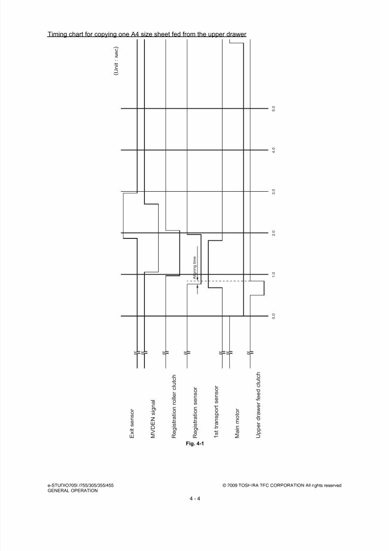
8/17/2019 Toshiba ES455 Service Manual
http://slidepdf.com/reader/full/toshiba-es455-service-manual 112/335
e-STUDIO205L/255/305/355/455 © 2009 TOSHIBA TEC CORPORATION All rights reservedGENERAL OPERATION
4 - 4
Timing chart for copying one A4 size sheet fed from the upper drawer
Fig. 4-1
0 . 0
1 . 0
2 . 0
3 . 0
4 . 0
5 . 0
A l i g n i n g t i m e
( U n i t : s e c )
E x i t s e n s o r
M V D E N
s i g n a l
R e g i s t r a t i o n r o l l e r c l u t c h
M a i n m o t o r
U p p e r d r a w e r f e e d c
l u t c h
R e g i s t r a t i o n s e n s o r
1 s t t r a n s p o r t s e n s o r

8/17/2019 Toshiba ES455 Service Manual
http://slidepdf.com/reader/full/toshiba-es455-service-manual 113/335
© 2009 TOSHIBA TEC CORPORATION All rights reserved e-STUDIO205L/255/305/355/455GENERAL OPERATION
4 - 5
4.2.4 Bypass feed copying
1. Insert a sheet of paper into the bypass tray.
→ Bypass paper sensor ON
- “Ready for bypass feeding” is displayed.
2. Press the [START] button
→ “Ready for bypass feeding” changes to “COPYING”
→ Exposure lamp ON
→Scan motor ON
Carriages -1 and -2 move forward
→ Polygonal motor rotates in high speed
→ Main motor and exit motor ON
- The drum, fuser unit, developer unit and exit roller are driven.
3. Bypass feeding
→ Main charger, developer bias and discharge LED ON. Fans are rotated in high speed.
→ Bypass feed clutch ON
- The bypass feed roller start to rotate.
→ Aligning operation
→ Paper reaches the registration roller
→ After a certain period of time, the bypass feed clutch OFF
4. Hereafter, the operation 3) through 6) of P.4-3 "4.2.3 Drawer feed copying (Upper drawer paper
feeding)" is repeated.
4.2.5 Interruption copying
1. Press the [INTERRUPT] button
→ LED “INTERRUPT” ON
→ Copying operation in progress is temporarily stopped. Carriages -1 and -2 return to appropriate
positions.
→ “Job interrupted job 1 saved” is displayed.
→ Automatic density and reproduction ratio 100% are set (The set number remains the same)
2. Select the desired copy condition
3. After the interruption copying is finished:
→ LED “INTERRUPT” OFF by pressing the [INTERRUPT] button
→ Equipment returns to the status before the interruption
→ “Ready to resume job 1” is displayed
4. Press the [START] button
→ The copying operation before the interruption is resumed.

8/17/2019 Toshiba ES455 Service Manual
http://slidepdf.com/reader/full/toshiba-es455-service-manual 114/335
e-STUDIO205L/255/305/355/455 © 2009 TOSHIBA TEC CORPORATION All rights reservedGENERAL OPERATION
4 - 6
4.3 Detection of AbnormalityWhen something abnormal has occurred in the equipment, the symbols corresponding to the type of
abnormality are displayed.
4.3.1 Types of abnormality
1. Abnormality cleared without turning OFF the door switch
(A) Add paper
(B) Pick-up failure in bypass
(C) Set key copy counter
2. Abnormality not cleared without turning OFF the door switch
(D) Misfeed in equipment
(E) Replace the toner cartridge
(F) EPU not installed properly
3. Abnormality not cleared without turning OFF the main switch
(G) Call for service
4.3.2 Description of abnormality
(A) Add paper • Drawer empty sensor detects the presence or absence of paper.
[When drawer is not installed]
No drawer detected
Tray not going up (drawer empty sensor OFF)
“Add paper” displayed
[START] button disabled
[When drawer is installed]
Drawer detected
Tray going up (drawer empty sensor OFF)
“Add paper” displayed
[START] button disabled

8/17/2019 Toshiba ES455 Service Manual
http://slidepdf.com/reader/full/toshiba-es455-service-manual 115/335
© 2009 TOSHIBA TEC CORPORATION All rights reserved e-STUDIO205L/255/305/355/455GENERAL OPERATION
4 - 7
(B) Pick-up failure in bypass ( )
• When the power is turned ON or the LCF drawer is inserted (when the power is turned ON or
equipment drawer / PFP drawers are inserted), LCF (PFP/equipment) performs initialization.
Detects the presence of paper
Tray-up motor ON – The tray goes up
At this time, the tray-up sensor and empty sensor are OFF.
When the tray-up sensor is not turned ON in a fixed period of time, it means thatthe tray is in abnormal condition.
“Add paper” is displayed regardless of presence/absence of paper.
Cleared by turning the drawer open/close
Tray-up sensor is turned ON in a fixed period of time.
- The tray motor stops.
At this time, if the empty sensor is ON: It is judged that there is paper.
OFF: It is judged that there is no paper.
Drawer area of the LCD panel blinks (When the drawer is selected)
• When the paper in the drawer runs out during copying,
The tray-up sensor turned OFF
The tray-up motor turned ON Tray goes up
The tray-up sensor turned ON Tray-up motor stopped.
• Empty sensor turned OFF during the copying in spite of the tray-up sensor is ON
It is judged that there is no paper.
Drawer area of the LCD panel blinks (When the drawer is selected)
The copying operation is stopped.
• During bypass feeding
Bypass feed clutch ON
1st transport sensor is not turned ON in a fixed period of time

8/17/2019 Toshiba ES455 Service Manual
http://slidepdf.com/reader/full/toshiba-es455-service-manual 116/335
e-STUDIO205L/255/305/355/455 © 2009 TOSHIBA TEC CORPORATION All rights reservedGENERAL OPERATION
4 - 8
(C) Set key copy counter
(D) Misfeed in equipment ( )
Clear paper symbol is displayed ( ): E120
Copying operation is disabled
Solution: The bypass paper sensor is turned OFF by removing the paper from the bypass tray.
• When the key copy counter (optional) is pulled out from the equipment which installs it:
“Set key copy counter” displayed
Copying operation disabled
• When the counter is pulled out during copying:
Copying is stopped when the key copy counter is pulled out.
“Set key copy counter” displayed
Copying operation disabled
• Exit sensor detects jamming of the leading edge of paper.
Registration clutch ON
Fig. 4-2
Less than regulation time
Exit sensor ON
If the exit sensor is not turned ON after the
regulation time
Paper jam (E010) The copying operation
is stopped
• Exit sensor detects jamming of the tailing edge of paper
Registration clutch
Exit sensor
Timer 0
Paper jam (E010)
ON
ON
Regulation time

8/17/2019 Toshiba ES455 Service Manual
http://slidepdf.com/reader/full/toshiba-es455-service-manual 117/335
© 2009 TOSHIBA TEC CORPORATION All rights reserved e-STUDIO205L/255/305/355/455GENERAL OPERATION
4 - 9
Registration clutch OFF
Fig. 4-3
Less than regulation time
Exit sensor OFF
If the exit sensor is not turned OFF after the
regulation time
Paper jam (E020) The copying operationis stopped
• Reverse sensor detects jamming of the leading edge of paper: e-STUDIO355/455
Exit sensor ON
Less than regulation time
Reverse sensor ON
If the reverse sensor is not turned ON after the
regulation time
Paper jam (E570) The copying operation
is stopped.
• Reverse sensor detects jamming of the tailing edge of paper: e-STUDIO355/455
Exit sensor OFF
Less than regulation time
Reverse sensor OFFIf the reverse sensor is not turned OFF after
the regulation time
Paper jam (E580) The copying operation
is stopped.
• Immediately after the power ON
Any of all sensors on paper transport path detects paper (ON)
Paper jam (E030)
• Front cover is opened during copying
Paper jam (E410)
Registration clutch
Exit sensor
Timer 0
Paper jam (E020)
ON
OFF
Regulation time

8/17/2019 Toshiba ES455 Service Manual
http://slidepdf.com/reader/full/toshiba-es455-service-manual 118/335
e-STUDIO205L/255/305/355/455 © 2009 TOSHIBA TEC CORPORATION All rights reservedGENERAL OPERATION
4 - 10
(E) Replace the toner cartridge ( )
(F) EPU not installed properly
(G) Call for service
Error code is displayed instead of the set number by pressing the [CLEAR] button and [8] button
simultaneously when the “Call for service” is blinking.
Refer to the error code table in the Service Handbook.
• Registration sensor detects jamming of the leading edge of paper:
Registration sensor is not turned ON in a fixed period of time after the leading edge of paper
passed the 1st transport sensor.
Paper jam (E200, E210, E270, E300, E330 and E3C0)
• During paper feeding from ADU:
Registration sensor is not turned ON in a fixed period of time after the ADU motor is turned ON.
Paper jam (E110)
• During paper transporting from ADU:
ADU entrance/exit sensors do not detect the paper at the fixed timing
Paper jam (E510 or E520)
• The 1st/2nd transport sensor and each sensors of PFP/LCF are not turned ON in a fixed period oftime after the feed clutch is turned ON
Paper jam (E220, E310, E320, E340–E360, E3D0 and E3E0: Error code differs depending on the
paper source.) Refer to the error code table in the Service Handbook.
• Toner density becomes low
Auto-toner sensor detects the absence of the toner
Control circuit “Install new toner cartridge” displayed: the copying operation disabled
Solution: Open the front cover and replace the toner cartridge with a new one.
Toner is supplied copying operation enabled.
• EPU not installed properly
“EPU not installed” is displayed.
Solution: Check if the connector between the EPU drawer and the developer unit is connected.
Then check if the EPU is installed in the equipment properly and close the front cover.
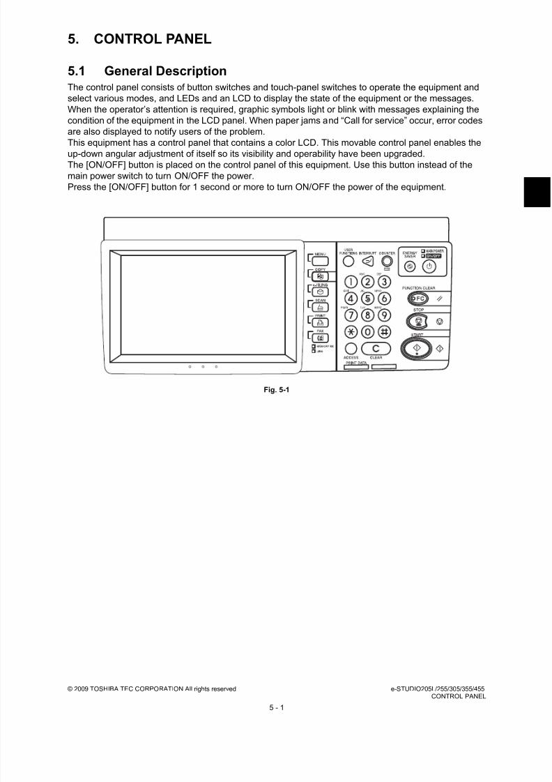
8/17/2019 Toshiba ES455 Service Manual
http://slidepdf.com/reader/full/toshiba-es455-service-manual 119/335
© 2009 TOSHIBA TEC CORPORATION All rights reserved e-STUDIO205L/255/305/355/455CONTROL PANEL
5 - 1
5. CONTROL PANEL
5.1 General DescriptionThe control panel consists of button switches and touch-panel switches to operate the equipment and
select various modes, and LEDs and an LCD to display the state of the equipment or the messages.
When the operator’s attention is required, graphic symbols light or blink with messages explaining the
condition of the equipment in the LCD panel. When paper jams and “Call for service” occur, error codes
are also displayed to notify users of the problem.
This equipment has a control panel that contains a color LCD. This movable control panel enables the
up-down angular adjustment of itself so its visibility and operability have been upgraded.
The [ON/OFF] button is placed on the control panel of this equipment. Use this button instead of the
main power switch to turn ON/OFF the power.
Press the [ON/OFF] button for 1 second or more to turn ON/OFF the power of the equipment.
Fig. 5-1
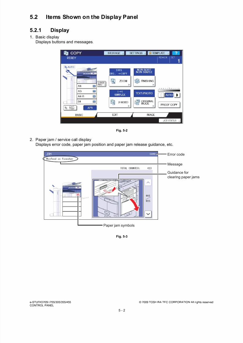
8/17/2019 Toshiba ES455 Service Manual
http://slidepdf.com/reader/full/toshiba-es455-service-manual 120/335
e-STUDIO205L/255/305/355/455 © 2009 TOSHIBA TEC CORPORATION All rights reservedCONTROL PANEL
5 - 2
5.2 Items Shown on the Display Panel
5.2.1 Display
1. Basic display
Displays buttons and messages.
Fig. 5-2
2. Paper jam / service call display
Displays error code, paper jam position and paper jam release guidance, etc.
Fig. 5-3
Error code
Message
Guidance for
clearing paper jams
Paper jam symbols

8/17/2019 Toshiba ES455 Service Manual
http://slidepdf.com/reader/full/toshiba-es455-service-manual 121/335
© 2009 TOSHIBA TEC CORPORATION All rights reserved e-STUDIO205L/255/305/355/455CONTROL PANEL
5 - 3
5.2.2 Message
No. Message State of equipment Note
1 - Power is OFF (at Sleep Mode) Press the [START] button or functionbutton to clear
2 Saving energy -press START button
At Energy Saving Mode Press the [START] button to clear
3 Wait Warming Up Scanner warming up
• Displayed until the equipmentbecomes ready to start scanning
Auto Start can be set
4 Wait Warming Up Auto Start
Scanner warming up• Displayed when Auto Start is set
Press the [STOP] button to clear the Auto Start.
5 WAIT Displayed when performing thecontrolling function to keep theequipment at the best condition
6 Wait adding toner Supplying toner • Equipment becomes the toner
supply state
Recovers when the toner supply hasfinished
7 READY Ready for copying• Waiting for the operation
8 READYPress START button tocopy
Copying job interrupted Press the [START] button to resumecopying or press [MEMORY CLEAR]button to delete the job
9 READY(WARMING UP)
Scanner warming up• Ready to scan the original
10 READY(PRINTING)
Printing out the data• Scanning is enabled
11 READY(ADDING TONER)
Supplying toner • Scanning is enabled
12 READY(INNER TRAY FULL)
Inner tray in the equipment is full• Scanning is enabled
- When the bridge unit is installed- Resumes printing by removingpaper from the tray
13 READY(CHECK STAPLER)
No staples in finisher • Scanning is enabled
Cleared by supplying staples
14 READY(CHECK STAPLER) Stapling jam occurred in finisher Cleared by supplying staples
15 READY(CHECK SADDLE STITCHSTAPLER)
No staples in saddle stitcher • Scanning is enabled
Cleared by supplying staples
16 READY(ADD PAPER)Press JOB STATUS button
No paper in drawer • Scanning is enabled
Cleared by supplying papers
17 READY(FINISHER FULL)
Finisher is full of paper • Scanning is enabled
Resumes printing by removing paperfrom the finisher
18 READY(HOLE PUNCH DUST BINIS FULL)
Punching dust box is full• Scanning is enabled
Resumes printing by removingpunching dust from the dust box
19 READY(SADDLE STITCH TRAYFULL)
Saddle stitcher tray is full of paper • Scanning is enabled
20 READY(CHANGE DRAWER TOCORRECT PAPER SIZE)
Incorrect paper size setting
21 Ready for bypass feeding Paper is set on the bypass tray
22 COPYING At the copying state
23 Auto Start Auto Start is set during printing Cleared by pressing [FUNCTIONCLEAR] button
24 Close Large CapacityFeeder
LCF drawer is not installed whenfeeding from LCF is set
Cleared by installing LCF drawer
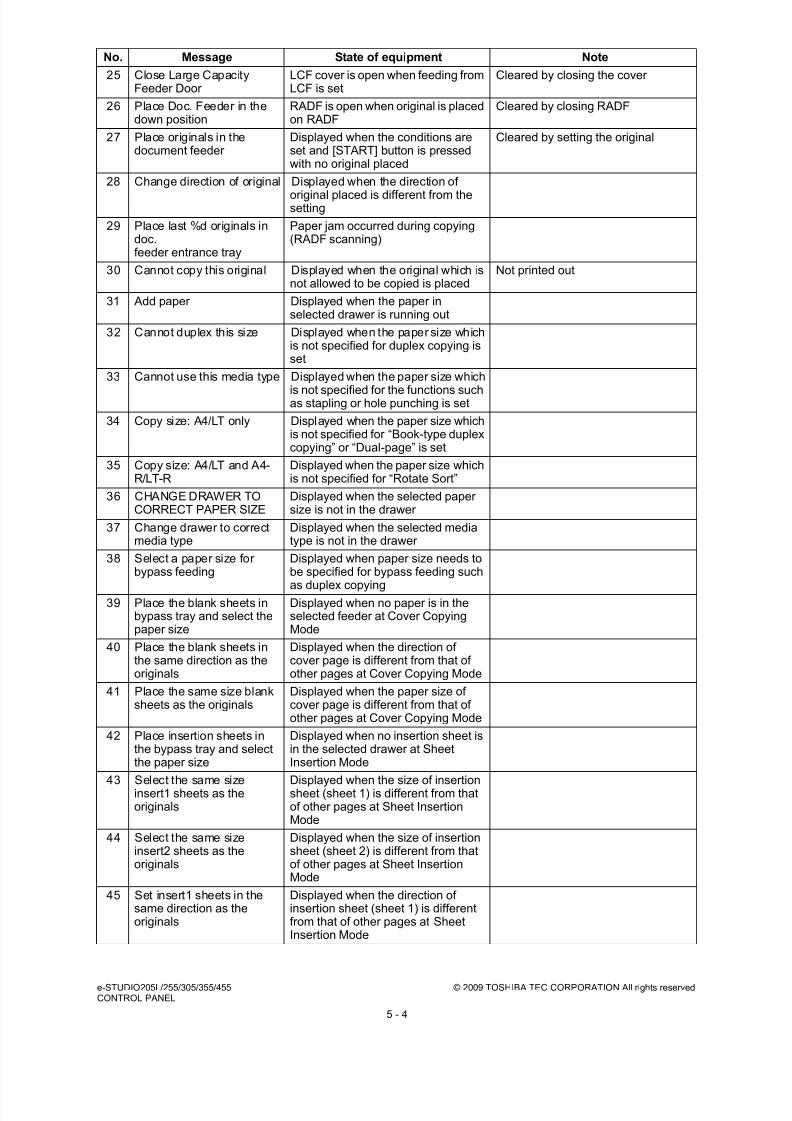
8/17/2019 Toshiba ES455 Service Manual
http://slidepdf.com/reader/full/toshiba-es455-service-manual 122/335
e-STUDIO205L/255/305/355/455 © 2009 TOSHIBA TEC CORPORATION All rights reservedCONTROL PANEL
5 - 4
25 Close Large CapacityFeeder Door
LCF cover is open when feeding fromLCF is set
Cleared by closing the cover
26 Place Doc. Feeder in thedown position
RADF is open when original is placedon RADF
Cleared by closing RADF
27 Place originals in thedocument feeder
Displayed when the conditions areset and [START] button is pressedwith no original placed
Cleared by setting the original
28 Change direction of original Displayed when the direction of
original placed is different from thesetting
29 Place last %d originals indoc.feeder entrance tray
Paper jam occurred during copying(RADF scanning)
30 Cannot copy this original Displayed when the original which isnot allowed to be copied is placed
Not printed out
31 Add paper Displayed when the paper inselected drawer is running out
32 Cannot duplex this size Displayed when the paper size whichis not specified for duplex copying isset
33 Cannot use this media type Displayed when the paper size which
is not specified for the functions suchas stapling or hole punching is set
34 Copy size: A4/LT only Displayed when the paper size whichis not specified for “Book-type duplexcopying” or “Dual-page” is set
35 Copy size: A4/LT and A4-R/LT-R
Displayed when the paper size whichis not specified for “Rotate Sort”
36 CHANGE DRAWER TOCORRECT PAPER SIZE
Displayed when the selected papersize is not in the drawer
37 Change drawer to correctmedia type
Displayed when the selected mediatype is not in the drawer
38 Select a paper size forbypass feeding
Displayed when paper size needs tobe specified for bypass feeding such
as duplex copying39 Place the blank sheets in
bypass tray and select thepaper size
Displayed when no paper is in theselected feeder at Cover CopyingMode
40 Place the blank sheets inthe same direction as theoriginals
Displayed when the direction ofcover page is different from that ofother pages at Cover Copying Mode
41 Place the same size blanksheets as the originals
Displayed when the paper size ofcover page is different from that ofother pages at Cover Copying Mode
42 Place insertion sheets inthe bypass tray and selectthe paper size
Displayed when no insertion sheet isin the selected drawer at SheetInsertion Mode
43 Select the same sizeinsert1 sheets as theoriginals
Displayed when the size of insertionsheet (sheet 1) is different from thatof other pages at Sheet InsertionMode
44 Select the same sizeinsert2 sheets as theoriginals
Displayed when the size of insertionsheet (sheet 2) is different from thatof other pages at Sheet InsertionMode
45 Set insert1 sheets in thesame direction as theoriginals
Displayed when the direction ofinsertion sheet (sheet 1) is differentfrom that of other pages at SheetInsertion Mode
No. Message State of equipment Note

8/17/2019 Toshiba ES455 Service Manual
http://slidepdf.com/reader/full/toshiba-es455-service-manual 123/335
© 2009 TOSHIBA TEC CORPORATION All rights reserved e-STUDIO205L/255/305/355/455CONTROL PANEL
5 - 5
46 Set insert2 sheets in thesame direction as theoriginals
Displayed when the direction ofinsertion sheet (sheet 2) is differentfrom that of other pages at SheetInsertion Mode
47 Set transparency film in A4/LT direction
Displayed when the selected papersize is other than A4/LT at OHPmode
48 CHECK PAPER IN LARGE
CAPACITY FEEDER
Papers in LCF are set incorrectly
49 CANNOT PUNCH THISSIZE PAPER
Displayed when the selected papersize is not specified for hole punching
50 Remove paper from thefinisher
Displayed when the paper sizes aremixed at Staple Sorting Mode
51 Cannot staple this size Displayed when the paper size is notspecified for stapling at StapleSorting Mode
52 Remove paper from thesaddle stitch unit
Finisher is full of papers
53 Examine stapler Trouble in the stapler unit in finisher
54 Check staple cartridge No stapler in finisher section
55 Check staple cartridge in
the saddle stitch unit
No stapler in saddle stitch unit
56 Job interrupted job 1 saved Interrupt copying is accepted
57 Ready to resume job 1 Interrupt copying is cancelled (finished)
58 Cannot use AMS mode Displayed when reproduction ratio isset to be over 200% at AMS Mode onRADF
Set the reproduction ratio 200% orbelow manually
59 More than 200% is notavailable
Displayed when reproduction ratio isset manually to be over 200% onRADF
Set the reproduction ratio 200% orbelow
60 Updated the templatesetting
Displayed when the template storedis recalled by pressing [TEMPLATE]button
61 Enter Department Code Displayed when a button is pressedwhile the department managementsetting is available
62 Cannot copyCheck DEPARTMENTCOUNTER
Displayed when the number ofprintouts exceeds the limit number ofdepartment counter
63 Not enough memory tostore original(s)Will you print out storedoriginals?
Displayed when confirming the userto print out the data as much asstored at memory - full state
64 Not enough memory tostore original(s)Will you send stored
originals in?
Displayed when confirming the userto send the FAX data as much asstored at memory - full state
Displayed only in FAX Function
65 Not enough memory tostore original(s)Will you save storedoriginals in?
Displayed when confirming the userto save the scanning data as muchas stored at memory-full state
Displayed only in FAX Function
66 The number of originalsexceeds the limitsWill you copy storedoriginals?
Displayed when confirming the userto print out the data as much asstored at memory-full state
67 The number of originalsexceeds the limits.Will you send storedoriginals?
Displayed when confirming the userto send the FAX data as much asstored at memory-full state
Displayed only in FAX Function
No. Message State of equipment Note
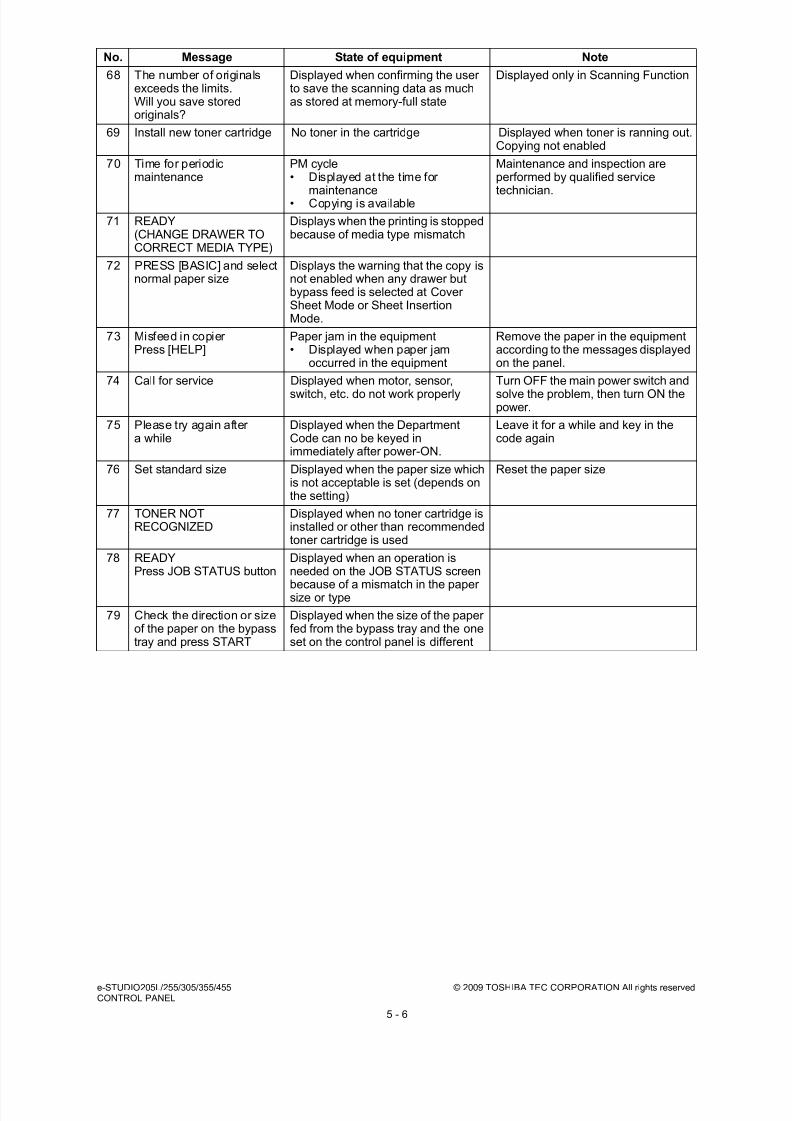
8/17/2019 Toshiba ES455 Service Manual
http://slidepdf.com/reader/full/toshiba-es455-service-manual 124/335

8/17/2019 Toshiba ES455 Service Manual
http://slidepdf.com/reader/full/toshiba-es455-service-manual 125/335

8/17/2019 Toshiba ES455 Service Manual
http://slidepdf.com/reader/full/toshiba-es455-service-manual 126/335
e-STUDIO205L/255/305/355/455 © 2009 TOSHIBA TEC CORPORATION All rights reservedCONTROL PANEL
5 - 8
Printing out
the copy
During paper
jam
When
interrupting
When displaying
HELP screen
During energy
saving mode
Press [ENERGYSAVER] button
Display notchanged
Display notchanged
Display notchanged
Switches to energysaving mode
Energy savingmode is clearedand displaysBASIC screen
Press[INTERRUPT]button
Display notchanged (LEDblinking)
Display notchanged
Returns to thestatus beforeinterrupting
Switches tointerrupting mode
Display notchanged
Press[FUNCTIONCLEAR] buttonafter setting thecopy mode
Copy mode iscleared after thecopy mode is set
Display notchanged
Copy mode iscleared afterthe copy modeis set
Displays BASICscreen after thecopy mode is setand then cancelled
Display notchanged
Press[STOP] button
Printing outstops, and“READY PressSTART to copy”and “MEMORYCLEAR” aredisplayed
Display notchanged
Display notchanged
Display notchanged
Display notchanged
Press [CLEAR]button aftersetting the copymode
Number ofprintoutschanges to 1while the settingremainsunchanged afterthe copy mode isset
Display notchanged
Number ofprintoutschanges to 1while thesetting remainsunchangedafter the copymode is set
Number ofprintouts changesto 1 while thesetting remainsunchanged afterthe copy mode isset
Display notchanged
Press [CLEAR]button afterkeying innumbers (digitalkeys)
Number keyed inchanges to 1after beingentered
Display notchanged
Number keyedin changes to 1after beingentered
Number keyed inchanges to 1 afterbeing entered
Display notchanged
Press [FAX]button
Displays FAXscreen
Display notchanged
Display notchanged
Displays FAXscreen
Displays FAXscreen
Press [COPY]button Display notchanged Display notchanged Display notchanged Display notchanged Displays COPYscreen
Press [SCAN]button
Displays SCANscreen
Display notchanged
Display notchanged
Displays SCANscreen
Displays SCANscreen
Press [USERFUNCTIONS]button
Displays USERFUNCTIONSscreen
Display notchanged
Display notchanged
Displays USERFUNCTIONSscreen
Display notchanged
Press [START]button with theoriginal set onRADF
Displays“COPYING” andRADF startsfeeding
Display notchanged
Displays“COPYING”and RADFstarts feeding
Displays “COPYING” andRADF startsfeeding
Energy savingmode is clearedand displaysBASIC screen
Press [MENU]button
Display notchanged
Display notchanged
Display notchanged
Displays MENUscreen
Displays MENUscreen
Press[COUNTER]button
Display notchanged Display notchanged Display notchanged DisplaysCOUNTER screen DisplaysCOUNTERscreen
Press [e-FILING]button
Displays E-FILING screen
Display notchanged
Display notchanged
Displays E-FILINGscreen
Displays E-FILING screen
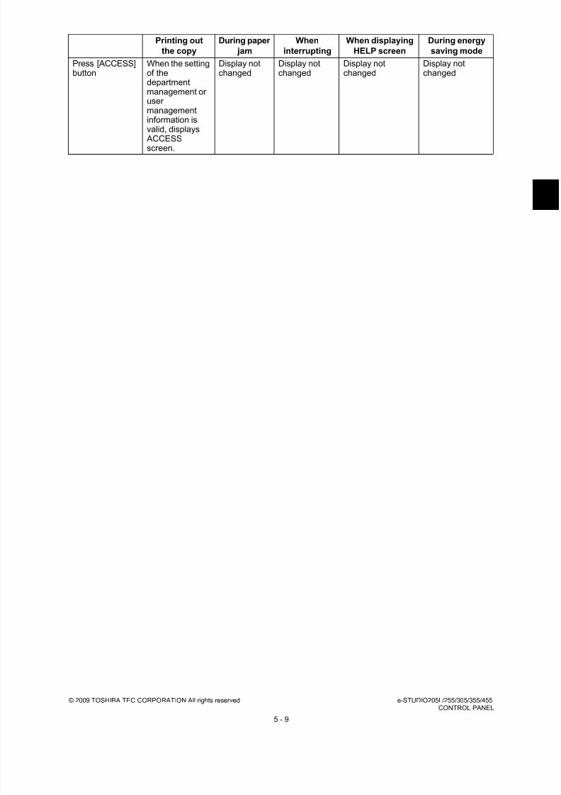
8/17/2019 Toshiba ES455 Service Manual
http://slidepdf.com/reader/full/toshiba-es455-service-manual 127/335
© 2009 TOSHIBA TEC CORPORATION All rights reserved e-STUDIO205L/255/305/355/455CONTROL PANEL
5 - 9
Press [ACCESS]button
When the settingof thedepartmentmanagement orusermanagementinformation isvalid, displays
ACCESSscreen.
Display notchanged
Display notchanged
Display notchanged
Display notchanged
Printing out
the copy
During paper
jam
When
interrupting
When displaying
HELP screen
During energy
saving mode

8/17/2019 Toshiba ES455 Service Manual
http://slidepdf.com/reader/full/toshiba-es455-service-manual 128/335
e-STUDIO205L/255/305/355/455 © 2009 TOSHIBA TEC CORPORATION All rights reservedCONTROL PANEL
5 - 10
5.4 Description of Operation
5.4.1 Dot matrix LCD circuit
1. Structure
Fig. 5-4
The DSP-LCD-470 is an TFT type LCD with (800 x R, G, B) x 480-dot display capacity. It consists of
a driver LSI, frame, printed circuit board, and straight type CCFL backlight.
* TFT: Thin Film Transistor
* CCFL: Cold Cathode Fluorescent Lamp
2. Block diagram
Fig. 5-5
800 x R,G,B x 480 dots
LCDPanel
Controller Y D r i v e r
X Driver
Backlight
R0 - R5
Inverter
G0 - G5 B0 - R5
CKV-SyncH-Sync
Enab
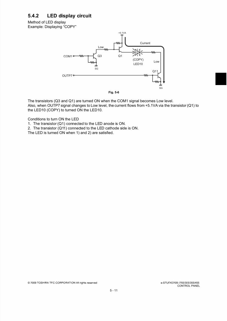
8/17/2019 Toshiba ES455 Service Manual
http://slidepdf.com/reader/full/toshiba-es455-service-manual 129/335
© 2009 TOSHIBA TEC CORPORATION All rights reserved e-STUDIO205L/255/305/355/455CONTROL PANEL
5 - 11
5.4.2 LED display circuit
Method of LED display
Example: Displaying “COPY”
Fig. 5-6
The transistors (Q3 and Q1) are turned ON when the COM1 signal becomes Low level.
Also, when OUTP7 signal changes to Low level, the current flows from +5.1VA via the transistor (Q1) to
the LED10 (COPY) to turned ON the LED10.
Conditions to turn ON the LED
1. The transistor (Q1) connected to the LED anode is ON.
2. The transistor (Q11) connected to the LED cathode side is ON.
The LED is turned ON when 1) and 2) are satisfied.
Low
Low(COPY)
LED10
G
Q11
Q1
+5.1VA
SG
SG
Q3COM1
OUTP7
Current

8/17/2019 Toshiba ES455 Service Manual
http://slidepdf.com/reader/full/toshiba-es455-service-manual 130/335
e-STUDIO205L/255/305/355/455 © 2009 TOSHIBA TEC CORPORATION All rights reservedCONTROL PANEL
5 - 12
5.5 Disassembly and Replacement
5.5.1 Stopper
5.5.2 Control panel unit
(1) Slide the stopper and pull it out.
Fig. 5-7
(2) Hook the stopper into the grooves of the rearcover.
Fig. 5-8
(1) Take off the front upper cover.
P.2-20 "2.5.2 Front upper cover"
(2) Lower the control panel and remove 2
screws.
Fig. 5-9
Control panel unit

8/17/2019 Toshiba ES455 Service Manual
http://slidepdf.com/reader/full/toshiba-es455-service-manual 131/335
© 2009 TOSHIBA TEC CORPORATION All rights reserved e-STUDIO205L/255/305/355/455CONTROL PANEL
5 - 13
(3) Release the hook and then take off the
control panel unit.
Fig. 5-10
(4) Remove the 3 screws and screw of the
clamp. Take off the cover.
Note:When installing the cover, set the cable in the
case.
Fig. 5-11
(5) Remove 1 screw and take out the clamp.
Fig. 5-12
Control panel unit
Cover

8/17/2019 Toshiba ES455 Service Manual
http://slidepdf.com/reader/full/toshiba-es455-service-manual 132/335
e-STUDIO205L/255/305/355/455 © 2009 TOSHIBA TEC CORPORATION All rights reservedCONTROL PANEL
5 - 14
5.5.3 Panel inverter board (P-INV)
5.5.4 Display board (DSP)
(6) Disconnect 1 connector, and then take off the
control panel unit.
Fig. 5-13
(1) Take off the control panel unit.
P.5-12 "5.5.2 Control panel unit"
(2) Remove 2 screws and disconnect 2connectors, and then take off the panel
inverter board.
Fig. 5-14
(1) Take off the control panel unit.
P.5-12 "5.5.2 Control panel unit"
(2) Disconnect 1 connector.
Fig. 5-15
Control panel unit
Panel inverter board
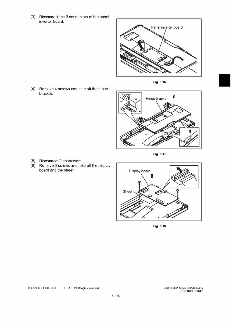
8/17/2019 Toshiba ES455 Service Manual
http://slidepdf.com/reader/full/toshiba-es455-service-manual 133/335
© 2009 TOSHIBA TEC CORPORATION All rights reserved e-STUDIO205L/255/305/355/455CONTROL PANEL
5 - 15
(3) Disconnect the 2 connectors of the panel
inverter board.
Fig. 5-16
(4) Remove 4 screws and take off the hinge
bracket.
Fig. 5-17
(5) Disconnect 2 connectors.
(6) Remove 3 screws and take off the display
board and the sheet.
Fig. 5-18
Panel inverter board
Hinge bracket
Display board
Sheet
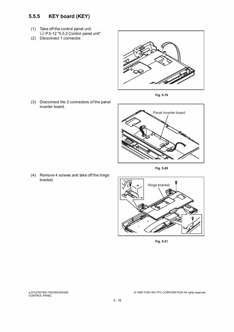
8/17/2019 Toshiba ES455 Service Manual
http://slidepdf.com/reader/full/toshiba-es455-service-manual 134/335
e-STUDIO205L/255/305/355/455 © 2009 TOSHIBA TEC CORPORATION All rights reservedCONTROL PANEL
5 - 16
5.5.5 KEY board (KEY)
(1) Take off the control panel unit.
P.5-12 "5.5.2 Control panel unit"
(2) Disconnect 1 connector.
Fig. 5-19
(3) Disconnect the 2 connectors of the panel
inverter board.
Fig. 5-20
(4) Remove 4 screws and take off the hingebracket.
Fig. 5-21
Panel inverter board
Hinge bracket

8/17/2019 Toshiba ES455 Service Manual
http://slidepdf.com/reader/full/toshiba-es455-service-manual 135/335
© 2009 TOSHIBA TEC CORPORATION All rights reserved e-STUDIO205L/255/305/355/455CONTROL PANEL
5 - 17
5.5.6 Touch panel (TCP)
5.5.7 Control panel cover
(5) Disconnect 1 connector and remove 12
screws. Take off the KEY board.
Fig. 5-22
(1) Take off the control panel unit.
P.5-12 "5.5.2 Control panel unit"
(2) Remove the DSP board. P.5-14 "5.5.4 Display board (DSP)"
(3) Remove 2 screws and take off the touch
panel.
Fig. 5-23
(1) Release the 4 latches, and take off the
control panel cover.
Fig. 5-24
KEY board
Touch panel
Control panel cover Latch
Latch

8/17/2019 Toshiba ES455 Service Manual
http://slidepdf.com/reader/full/toshiba-es455-service-manual 136/335
e-STUDIO205L/255/305/355/455 © 2009 TOSHIBA TEC CORPORATION All rights reservedCONTROL PANEL
5 - 18
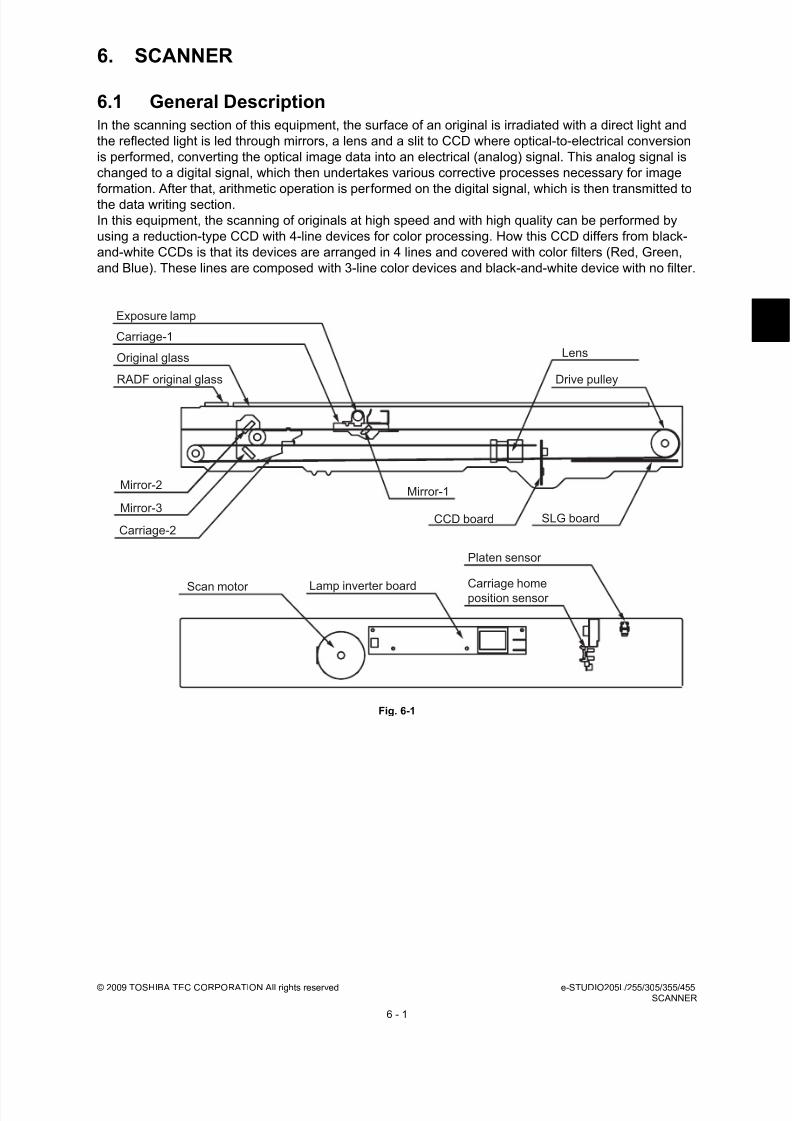
8/17/2019 Toshiba ES455 Service Manual
http://slidepdf.com/reader/full/toshiba-es455-service-manual 137/335
© 2009 TOSHIBA TEC CORPORATION All rights reserved e-STUDIO205L/255/305/355/455SCANNER
6 - 1
6. SCANNER
6.1 General DescriptionIn the scanning section of this equipment, the surface of an original is irradiated with a direct light and
the reflected light is led through mirrors, a lens and a slit to CCD where optical-to-electrical conversion
is performed, converting the optical image data into an electrical (analog) signal. This analog signal is
changed to a digital signal, which then undertakes various corrective processes necessary for image
formation. After that, arithmetic operation is performed on the digital signal, which is then transmitted to
the data writing section.
In this equipment, the scanning of originals at high speed and with high quality can be performed by
using a reduction-type CCD with 4-line devices for color processing. How this CCD differs from black-
and-white CCDs is that its devices are arranged in 4 lines and covered with color filters (Red, Green,
and Blue). These lines are composed with 3-line color devices and black-and-white device with no filter.
Fig. 6-1
RADF original glass
Original glass
Carriage-1
Exposure lamp
Mirror-2
Mirror-3
Carriage-2CCD board SLG board
Drive pulley
Lens
Mirror-1
Scan motor Lamp inverter board Carriage homeposition sensor
Platen sensor

8/17/2019 Toshiba ES455 Service Manual
http://slidepdf.com/reader/full/toshiba-es455-service-manual 138/335
e-STUDIO205L/255/305/355/455 © 2009 TOSHIBA TEC CORPORATION All rights reservedSCANNER
6 - 2
6.2 Construction
Scanner
Original glass Original glass
RADF original glass
Carriage-1 Exposure lamp (EXP) Xenon lamp (17W)
Reflector
Mirror-1
Carriage-2 Mirror-2
Mirror-3
Lens unit
CCD driving PCboard (CCD)
Scanning sectioncontrol PC board(SLG)
Automatic originaldetection sensor(S1-5)
Lamp inverter
board (INV)Driving section Scan motor (M1) • 2-phase stepping motor
• Wire drive• Driving the carriage-1 and carriage-2
Other Carriage home position sensor (S7)
Platen sensor (S6)
Rubber damper
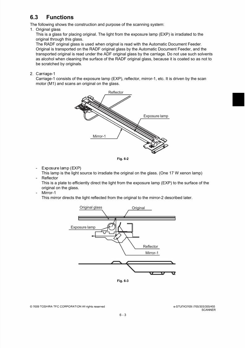
8/17/2019 Toshiba ES455 Service Manual
http://slidepdf.com/reader/full/toshiba-es455-service-manual 139/335
© 2009 TOSHIBA TEC CORPORATION All rights reserved e-STUDIO205L/255/305/355/455SCANNER
6 - 3
6.3 FunctionsThe following shows the construction and purpose of the scanning system:
1. Original glass
This is a glass for placing original. The light from the exposure lamp (EXP) is irradiated to the
original through this glass.
The RADF original glass is used when original is read with the Automatic Document Feeder.
Original is transported on the RADF original glass by the Automatic Document Feeder, and the
transported original is read under the ADF original glass by the carriage. Do not use such solvents
as alcohol when cleaning the surface of the RADF original glass, because it is coated so as not tobe scratched by originals.
2. Carriage-1
Carriage-1 consists of the exposure lamp (EXP), reflector, mirror-1, etc. It is driven by the scan
motor (M1) and scans an original on the glass.
Fig. 6-2
- Exposure lamp (EXP)
This lamp is the light source to irradiate the original on the glass. (One 17 W xenon lamp)
- Reflector
This is a plate to efficiently direct the light from the exposure lamp (EXP) to the surface of theoriginal on the glass.
- Mirror-1
This mirror directs the light reflected from the original to the mirror-2 described later.
Fig. 6-3
Mirror-1
Exposure lamp
Reflector
Original glass Original
Exposure lamp
Reflector
Mirror-1

8/17/2019 Toshiba ES455 Service Manual
http://slidepdf.com/reader/full/toshiba-es455-service-manual 140/335
e-STUDIO205L/255/305/355/455 © 2009 TOSHIBA TEC CORPORATION All rights reservedSCANNER
6 - 4
3. Carriage-2
Carriage-2 mainly consists of the mirror-2, mirror-3, etc. and directs the reflected light from the
mirror-1 through the mirrors-2 and -3 to the lens.
This carriage is driven by the same scan motor (M1) as that for the carriage-1 at half the scanning
speed of the carriage-1 (The scanning distance is also half that of the carriage-1).
Fig. 6-4
4. Lens unit
The light reflected from the mirror-3 is led to the CCD placed at the focal point of the lens which is
fixed in a position.
5. CCD driving PC board (CCD)
Processes such as signal amplification and A/D conversion are applied on the electrical signal
which was converted by CCD.
Fig. 6-5
6. Scanning section control PC board (SLG)This is a board to perform the image correction, such as the shading correction and 3-line
correction, and control the scan motor (M1).
7. Automatic original detection sensor (S1-5)
The size of an original placed on the glass is instantly detected using the automatic original
detection sensors (S1-5) fixed on the base frame without moving the carriage-1.
Mirror-3
Mirror-2
Lens unit CCD driving PC board

8/17/2019 Toshiba ES455 Service Manual
http://slidepdf.com/reader/full/toshiba-es455-service-manual 141/335
© 2009 TOSHIBA TEC CORPORATION All rights reserved e-STUDIO205L/255/305/355/455SCANNER
6 - 5
8. Lamp inverter board (INV)
Controls lighting of the exposure lamp (EXP).
It is installed on the rear side since the scanner thickness is reduced.
Fig. 6-6
Lamp inverter board

8/17/2019 Toshiba ES455 Service Manual
http://slidepdf.com/reader/full/toshiba-es455-service-manual 142/335
e-STUDIO205L/255/305/355/455 © 2009 TOSHIBA TEC CORPORATION All rights reservedSCANNER
6 - 6
6.4 Description of Operation
6.4.1 Scanning operation
Fig. 6-7
• Scanning of an original placed on the original glass
This motor drives the carriages-1 and -2 through the timing belt and carriage wire. First, the scan
motor drives the carriages-1 and -2 to their respective home positions. The home positions are
detected when the carriage-1 passes the carriage home position sensor (S7). When the [START]button is pressed, the both carriages start to move and scan the original on the glass.
• Scanning of an original placed on the RADF
It stops at the scanning position and starts scanning, and performs shading correction before
scanning and at constant intervals during scanning.
• Scanning speed
The carriage speed of the original in the color scanning mode is half of that in the black and white
scanning mode.
Scan motor Carriage-1
Motor speed-reduction pulley Carriage-2
Idler pulleyMotor pulley

8/17/2019 Toshiba ES455 Service Manual
http://slidepdf.com/reader/full/toshiba-es455-service-manual 143/335
© 2009 TOSHIBA TEC CORPORATION All rights reserved e-STUDIO205L/255/305/355/455SCANNER
6 - 7
6.5 Electric Circuit Description
6.5.1 Scan motor control circuit
The scan motor is a stepping motor driven by the control signal output from the scanner CPU on the
SLG board and drives carriage-1 and -2.
The scan motor is driven by the pulse signal (SCNM-A, SCNM-AB, SCNM-B, SCNM-BB) output from
the motor driver. These pulse signals are formed based on the reference clock (MOTCLK) and output
only when the enable signal (MOTEN) is a low level. Also, the rotation speed or direction of the motor
can be switched by changing the output timing of each pulse signal.
Fig. 6-8
Control signal
* CW: Clockwise rotation, CCW: Counter clockwise rotation viewing from the axis
Signal FunctionStatus
High level Low level
MOTCLK Reference clock --- ---
MOTEN Enable signal ON OFF
MOTDIR Rotation direction signal CCW CWMOTRST Reset signal Normal operation Reset
MOTREF Motor current setting Analog signal
IC10
Scanner CPU
Reset signalgeneration circuit
MOTEN
MOTCLK
Scan motor
MOTDIR
SCNM-AB
SCNM-A
SCNM-BB
SCNM-B
IC2
Motor driver
SLG board +24VMT(+24VD4)
+24VMT(+24VD4)+5.1VB
SG +24VMTGN D(PG)
MOTRST
MOTREF

8/17/2019 Toshiba ES455 Service Manual
http://slidepdf.com/reader/full/toshiba-es455-service-manual 144/335
e-STUDIO205L/255/305/355/455 © 2009 TOSHIBA TEC CORPORATION All rights reservedSCANNER
6 - 8
6.5.2 Exposure lamp control circuit
[ 1 ] General description
Control circuit for the exposure lamp consists of the following two blocks:
1. Lighting device for the exposure lamp (Lamp inverter board)
Turns ON/OFF the exposure lamp.
2. CCD boardThis circuit converts the reflected light amount from the original surface and the shading correction
plate to electrical signals. The exposure amount is controlled in two ways:
- White reference formation - reads the reflected light amount from the white shading correction
plate
- Black reference formation - reads the light amount at the regulation position with the exposure
lamp lights OFF
Fig. 6-9
Exposure lamp (Xenon lamp)
Shading correction plateOriginal
Lighting device for
exposure lamp
(Lamp inverter board)
CCD board
CCD sensor
SLG board
A/DScanner
CPU
ASIC IMG board

8/17/2019 Toshiba ES455 Service Manual
http://slidepdf.com/reader/full/toshiba-es455-service-manual 145/335
© 2009 TOSHIBA TEC CORPORATION All rights reserved e-STUDIO205L/255/305/355/455SCANNER
6 - 9
[ 2 ] Exposure lamp
External electrode type xenon fluorescent lamp is used as an exposure lamp in this equipment.
1. Structure
Fluorescer is applied on the inside surface of the lamp pipe (except a part to be an opening) which is
filled with the xenon gas.
A pair of the external electrodes covered by the film with the adhesive agent is attached over the
pipe.
Fig. 6-10
2. Behavior inside the lamp
The electron inside the pipe is led to the electric field by applying voltage to the pair of the external
electrodes, and discharge is started. Electrons then flow and clash with the xenon atoms inside the
pipe to excite them, and generate ultraviolet rays. These ultraviolet rays excite the fluorescent
substance to generate visible light.
Fig. 6-11
PET film
Aluminum tape
electrode
Adhesive agent, PET, film
Glass valve
Fluorescer
Xenon gas
(2)(7)
(5)
(4)
(3)
(1)(6)
(1) Electrode (2) Electron (3) Xenon atom
(4) Ultraviolet lay (5) Fluorescer
(6) Visible light (irradiated from the opening to outside the pipe)
(7) Opening (8) Harness
(8)
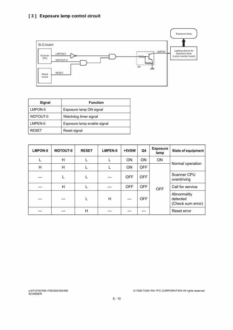
8/17/2019 Toshiba ES455 Service Manual
http://slidepdf.com/reader/full/toshiba-es455-service-manual 146/335
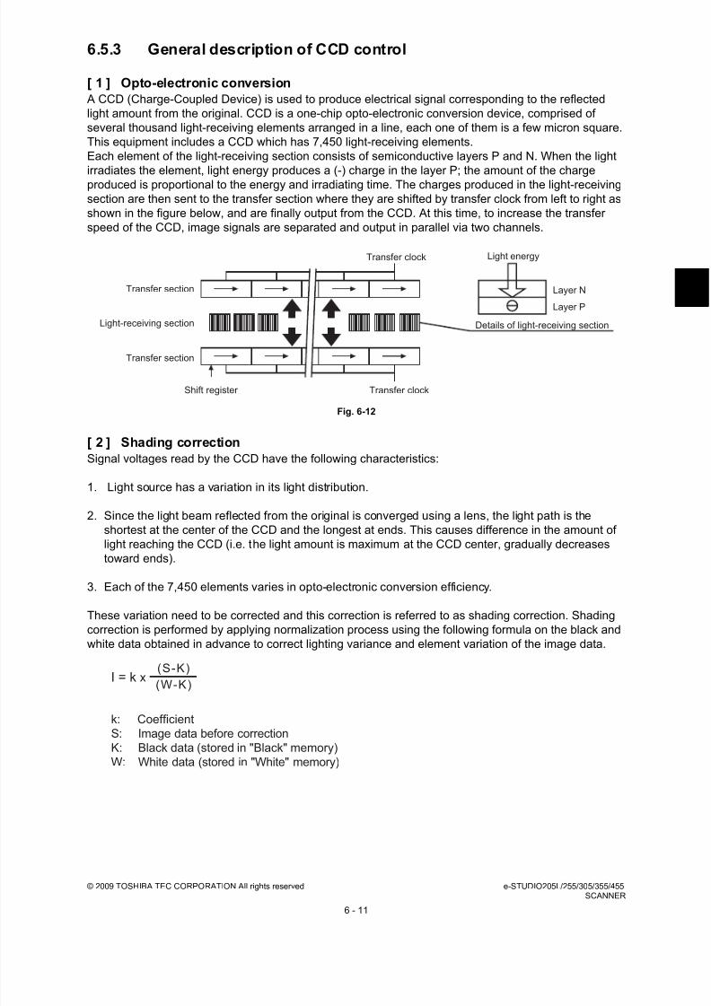
8/17/2019 Toshiba ES455 Service Manual
http://slidepdf.com/reader/full/toshiba-es455-service-manual 147/335
© 2009 TOSHIBA TEC CORPORATION All rights reserved e-STUDIO205L/255/305/355/455SCANNER
6 - 11
6.5.3 General description of CCD control
[ 1 ] Opto-electronic conversion
A CCD (Charge-Coupled Device) is used to produce electrical signal corresponding to the reflected
light amount from the original. CCD is a one-chip opto-electronic conversion device, comprised of
several thousand light-receiving elements arranged in a line, each one of them is a few micron square.
This equipment includes a CCD which has 7,450 light-receiving elements.
Each element of the light-receiving section consists of semiconductive layers P and N. When the light
irradiates the element, light energy produces a (-) charge in the layer P; the amount of the chargeproduced is proportional to the energy and irradiating time. The charges produced in the light-receiving
section are then sent to the transfer section where they are shifted by transfer clock from left to right as
shown in the figure below, and are finally output from the CCD. At this time, to increase the transfer
speed of the CCD, image signals are separated and output in parallel via two channels.
Fig. 6-12
[ 2 ] Shading correction
Signal voltages read by the CCD have the following characteristics:
1. Light source has a variation in its light distribution.
2. Since the light beam reflected from the original is converged using a lens, the light path is the
shortest at the center of the CCD and the longest at ends. This causes difference in the amount oflight reaching the CCD (i.e. the light amount is maximum at the CCD center, gradually decreases
toward ends).
3. Each of the 7,450 elements varies in opto-electronic conversion efficiency.
These variation need to be corrected and this correction is referred to as shading correction. Shading
correction is performed by applying normalization process using the following formula on the black and
white data obtained in advance to correct lighting variance and element variation of the image data.
Transfer clock
Transfer section
Transfer section
Light-receiving section
Light energy
Layer N
Layer P
Transfer clockShift register
Details of light-receiving section
(S-K)
(W-K)I = k x
k: Coefficient
S: Image data before correction
K: Black data (stored in "Black" memory)
W: White data (stored in "White" memory)
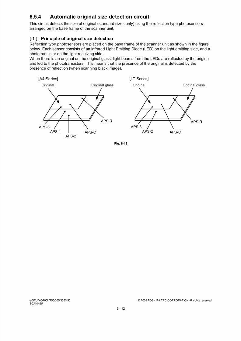
8/17/2019 Toshiba ES455 Service Manual
http://slidepdf.com/reader/full/toshiba-es455-service-manual 148/335
e-STUDIO205L/255/305/355/455 © 2009 TOSHIBA TEC CORPORATION All rights reservedSCANNER
6 - 12
6.5.4 Automatic original size detection circuit
This circuit detects the size of original (standard sizes only) using the reflection type photosensors
arranged on the base frame of the scanner unit.
[ 1 ] Principle of original size detection
Reflection type photosensors are placed on the base frame of the scanner unit as shown in the figure
below. Each sensor consists of an infrared Light Emitting Diode (LED) on the light emitting side, and a
phototransistor on the light receiving side.
When there is an original on the original glass, light beams from the LEDs are reflected by the originaland led to the phototransistors. This means that the presence of the original is detected by the
presence of reflection (when scanning black image).
Fig. 6-13
Original Original glass
[ A4 Series] [LT Series]
Original Original glass
APS-3
APS-1
APS-2 APS-C
APS-R
APS-3
APS-2 APS-C
APS-R
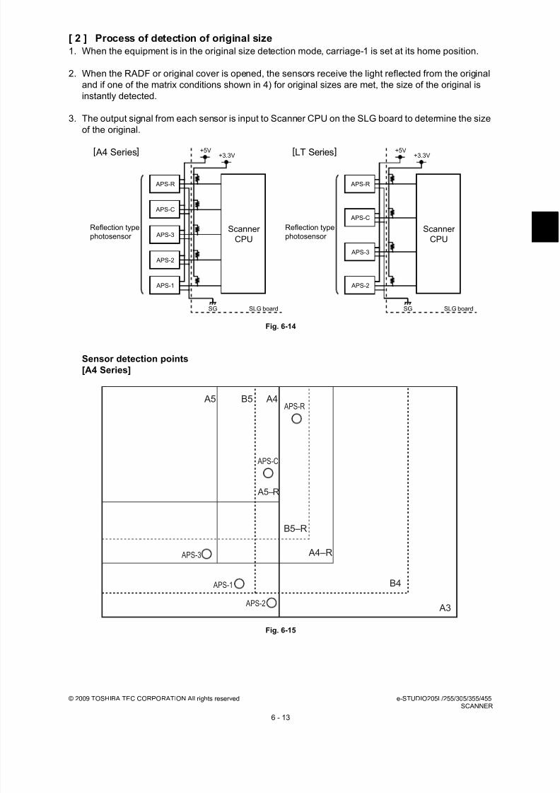
8/17/2019 Toshiba ES455 Service Manual
http://slidepdf.com/reader/full/toshiba-es455-service-manual 149/335
© 2009 TOSHIBA TEC CORPORATION All rights reserved e-STUDIO205L/255/305/355/455SCANNER
6 - 13
[ 2 ] Process of detection of original size
1. When the equipment is in the original size detection mode, carriage-1 is set at its home position.
2. When the RADF or original cover is opened, the sensors receive the light reflected from the original
and if one of the matrix conditions shown in 4) for original sizes are met, the size of the original is
instantly detected.
3. The output signal from each sensor is input to Scanner CPU on the SLG board to determine the size
of the original.
Fig. 6-14
Sensor detection points
[A4 Series]
Fig. 6-15
SLG board
APS-C
APS-3
APS-2
APS-R
Scanner
CPU
+5V+3.3V
+5V+3.3V
SG SGSLG board
APS-C
APS-2
APS-3
APS-1
APS-R
Scanner
CPU
Reflection type
photosensor
Reflection type
photosensor
[ A4 Series] [LT Series]
A5 B5 A4
B4
A3
A5–R
A4–R
B5–R
APS-R
APS-C
APS-3
APS-1
APS-2
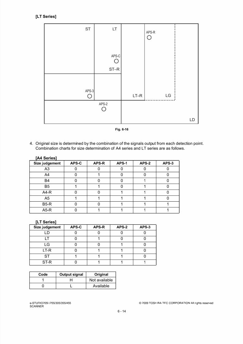
8/17/2019 Toshiba ES455 Service Manual
http://slidepdf.com/reader/full/toshiba-es455-service-manual 150/335
e-STUDIO205L/255/305/355/455 © 2009 TOSHIBA TEC CORPORATION All rights reservedSCANNER
6 - 14
[LT Series]
Fig. 6-16
4. Original size is determined by the combination of the signals output from each detection point.
Combination charts for size determination of A4 series and LT series are as follows.
[A4 Series]
[LT Series]
Size judgement APS-C APS-R APS-1 APS-2 APS-3
A3 0 0 0 0 0
A4 0 1 0 0 0
B4 0 0 0 1 0B5 1 1 0 1 0
A4-R 0 0 1 1 0
A5 1 1 1 1 0
B5-R 0 0 1 1 1
A5-R 0 1 1 1 1
Size judgement APS-C APS-R APS-2 APS-3
LD 0 0 0 0
LT 0 1 0 0
LG 0 0 1 0
LT-R 0 1 1 0
ST 1 1 1 0
ST-R 0 1 1 1
Code Output signal Original
1 H Not available
0 L Available
ST LT
LG
LD
ST–R
LT–R
APS-R
APS-C
APS-3
APS-2
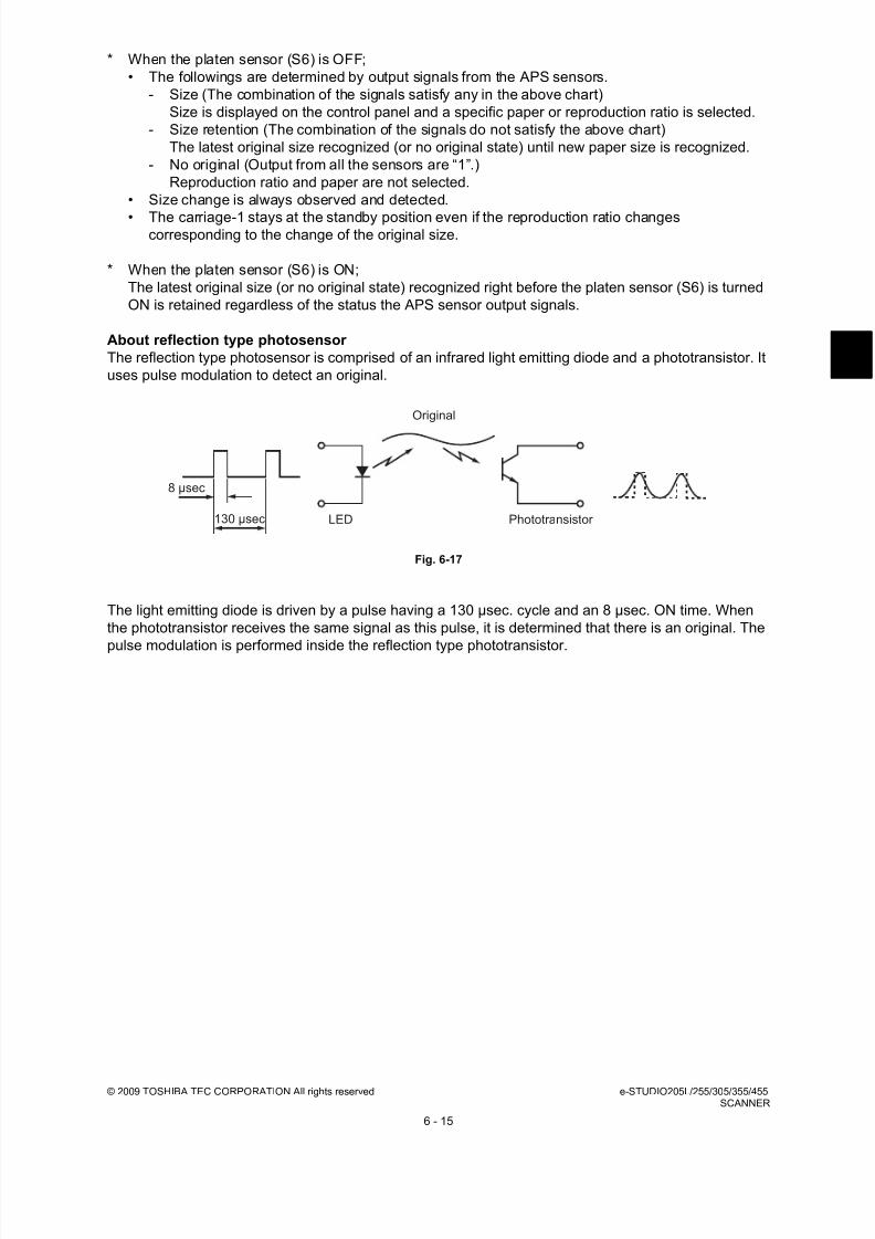
8/17/2019 Toshiba ES455 Service Manual
http://slidepdf.com/reader/full/toshiba-es455-service-manual 151/335
© 2009 TOSHIBA TEC CORPORATION All rights reserved e-STUDIO205L/255/305/355/455SCANNER
6 - 15
* When the platen sensor (S6) is OFF;
• The followings are determined by output signals from the APS sensors.
- Size (The combination of the signals satisfy any in the above chart)
Size is displayed on the control panel and a specific paper or reproduction ratio is selected.
- Size retention (The combination of the signals do not satisfy the above chart)
The latest original size recognized (or no original state) until new paper size is recognized.
- No original (Output from all the sensors are “1”.)
Reproduction ratio and paper are not selected.
• Size change is always observed and detected.
• The carriage-1 stays at the standby position even if the reproduction ratio changescorresponding to the change of the original size.
* When the platen sensor (S6) is ON;
The latest original size (or no original state) recognized right before the platen sensor (S6) is turned
ON is retained regardless of the status the APS sensor output signals.
About reflection type photosensor
The reflection type photosensor is comprised of an infrared light emitting diode and a phototransistor. It
uses pulse modulation to detect an original.
Fig. 6-17
The light emitting diode is driven by a pulse having a 130 µsec. cycle and an 8 µsec. ON time. When
the phototransistor receives the same signal as this pulse, it is determined that there is an original. The
pulse modulation is performed inside the reflection type phototransistor.
130 µsec LED Phototransistor
Original
8 µsec
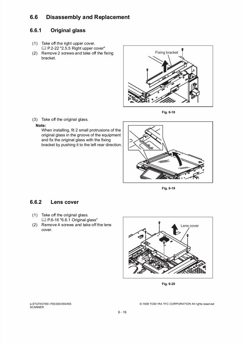
8/17/2019 Toshiba ES455 Service Manual
http://slidepdf.com/reader/full/toshiba-es455-service-manual 152/335
e-STUDIO205L/255/305/355/455 © 2009 TOSHIBA TEC CORPORATION All rights reservedSCANNER
6 - 16
6.6 Disassembly and Replacement
6.6.1 Original glass
6.6.2 Lens cover
(1) Take off the right upper cover.
P.2-22 "2.5.5 Right upper cover"
(2) Remove 2 screws and take off the fixing
bracket.
Fig. 6-18
(3) Take off the original glass.Note:
When installing, fit 2 small protrusions of the
original glass in the groove of the equipment
and fix the original glass with the fixing
bracket by pushing it to the left rear direction.
Fig. 6-19
(1) Take off the original glass.
P.6-16 "6.6.1 Original glass"
(2) Remove 4 screws and take off the lens
cover.
Fig. 6-20
Fixing bracket
Lens cover

8/17/2019 Toshiba ES455 Service Manual
http://slidepdf.com/reader/full/toshiba-es455-service-manual 153/335
© 2009 TOSHIBA TEC CORPORATION All rights reserved e-STUDIO205L/255/305/355/455SCANNER
6 - 17
6.6.3 Automatic original detection sensor (S1-5)
[A] A4 series (APS-1, -2, -3, -C, -R)
[B] LT series (APS-1, -3, -C, -R)
(1) Take off the lens cover.
P.6-16 "6.6.2 Lens cover"
(2) Disconnect 1 connector and remove 1 screw.
Take off APS sensor.
Fig. 6-21
(3) Disconnect 1 connector each, release 2
latches each and take off 4 APS sensors.
Fig. 6-22
(1) Take off the lens cover.
P.6-16 "6.6.2 Lens cover"
(2) Disconnect 1 connector and remove 1 screw.
Take off APS sensor.
Fig. 6-23
Latch

8/17/2019 Toshiba ES455 Service Manual
http://slidepdf.com/reader/full/toshiba-es455-service-manual 154/335
e-STUDIO205L/255/305/355/455 © 2009 TOSHIBA TEC CORPORATION All rights reservedSCANNER
6 - 18
6.6.4 Exposure lamp (EXP)
(3) Disconnect 1 connector and remove 1 screw
for each APS sensor. Take off 3 APS
sensors.
Fig. 6-24
(1) Take off the original glass.
P.6-16 "6.6.1 Original glass"
(2) Take off the front upper cover. P.2-20 "2.5.2 Front upper cover"
(3) Release the harness from 1 harness clamp.
Fig. 6-25
(4) Release the harness from the harness guide.
Fig. 6-26
Latch

8/17/2019 Toshiba ES455 Service Manual
http://slidepdf.com/reader/full/toshiba-es455-service-manual 155/335
© 2009 TOSHIBA TEC CORPORATION All rights reserved e-STUDIO205L/255/305/355/455SCANNER
6 - 19
(5) Rotate the drive pulley and move the
carriage-1 so that the screw can be seen.
Fig. 6-27
(6) Take off the rear cover.
P.2-22 "2.5.6 Rear cover"
(7) Disconnect the connector of the lamp
harness from the lamp inverter board.
Note:
Be careful not to apply load to the lampinverter board when disconnecting the
connector.
See the following chapter for the installation
procedure.
P.6-28 "6.6.9 Installing the lamp harness"
Fig. 6-28
(8) Release 1 clamp of the carriage and take off
the harness wiring on the rear frame.
Fig. 6-29
Lamp inverter board
Clamp

8/17/2019 Toshiba ES455 Service Manual
http://slidepdf.com/reader/full/toshiba-es455-service-manual 156/335
e-STUDIO205L/255/305/355/455 © 2009 TOSHIBA TEC CORPORATION All rights reservedSCANNER
6 - 20
6.6.5 Lens unit
(9) Release the harness from the harness
holder.
Fig. 6-30
(10) Remove 1 screw.
(11) Lift up the front side of the exposure lamp
and take off by sliding it.
Fig. 6-31
(1) Remove the lens cover.
P.6-16 "6.6.2 Lens cover"
(2) Remove 1 screw and take off the APS
sensor.
Fig. 6-32
Exposure lamp

8/17/2019 Toshiba ES455 Service Manual
http://slidepdf.com/reader/full/toshiba-es455-service-manual 157/335
© 2009 TOSHIBA TEC CORPORATION All rights reserved e-STUDIO205L/255/305/355/455SCANNER
6 - 21
(3) Disconnect 1 connector and remove 4
screws. Take off the lens unit.
Fig. 6-33
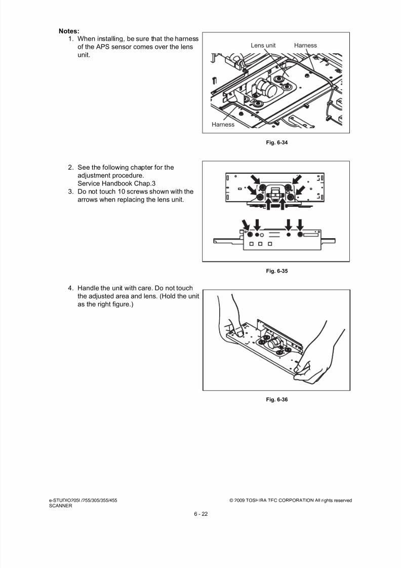
8/17/2019 Toshiba ES455 Service Manual
http://slidepdf.com/reader/full/toshiba-es455-service-manual 158/335
e-STUDIO205L/255/305/355/455 © 2009 TOSHIBA TEC CORPORATION All rights reservedSCANNER
6 - 22
Notes:1. When installing, be sure that the harness
of the APS sensor comes over the lens
unit.
2. See the following chapter for the
adjustment procedure.
Service Handbook Chap.3
3. Do not touch 10 screws shown with the
arrows when replacing the lens unit.
4. Handle the unit with care. Do not touch
the adjusted area and lens. (Hold the unitas the right figure.)
Fig. 6-34
Fig. 6-35
Fig. 6-36
HarnessLens unit
Harness

8/17/2019 Toshiba ES455 Service Manual
http://slidepdf.com/reader/full/toshiba-es455-service-manual 159/335
© 2009 TOSHIBA TEC CORPORATION All rights reserved e-STUDIO205L/255/305/355/455SCANNER
6 - 23
6.6.6 Scan motor (M1)
(1) Take off the rear cover.
P.2-22 "2.5.6 Rear cover"
(2) Take off the upper rear cover.
P.2-23 "2.5.7 Upper rear cover"
(3) Disconnect 1 connector.
Fig. 6-37
(4) Remove 2 screws and take off the scan
motor with the whole bracket.
Fig. 6-38
Notes:When installing the scan motor, use the belt
tension jig (spring). The procedure is as
follows.
1. Temporarily fix the screw A and B.
P.6-23 "Fig. 6-38 "
2. Hook the belt tension jig to the motor
bracket and the flame.
3. The scan motor is pulled by the belt
tension jig. Fix the screw A and then B at
the stopped position.
4. Remove the belt tension jig.
Fig. 6-39
A
Scan motor
B
Belt tension jig

8/17/2019 Toshiba ES455 Service Manual
http://slidepdf.com/reader/full/toshiba-es455-service-manual 160/335
e-STUDIO205L/255/305/355/455 © 2009 TOSHIBA TEC CORPORATION All rights reservedSCANNER
6 - 24
6.6.7 Carriage-1
(1) Take off the original glass.
P.6-16 "6.6.1 Original glass"
(2) Take off the upper rear cover.
P.2-23 "2.5.7 Upper rear cover"
(3) Take off the front upper cover.
P.2-20 "2.5.2 Front upper cover"
(4) Release the harness from 1 harness clamp.
Fig. 6-40
(5) Release the harness from the harness guide.
Fig. 6-41
(6) Rotate the drive pulley and move thecarriage-1 so that the screw can be seen.
Fig. 6-42

8/17/2019 Toshiba ES455 Service Manual
http://slidepdf.com/reader/full/toshiba-es455-service-manual 161/335
© 2009 TOSHIBA TEC CORPORATION All rights reserved e-STUDIO205L/255/305/355/455SCANNER
6 - 25
(7) Disconnect the connector of the lamp
harness from the lamp inverter board.
Note:Be careful not to apply load to the lamp
inverter board when disconnecting the
connector.
See the following chapter for the installation
procedure.
P.6-28 "6.6.9 Installing the lamp harness"
Fig. 6-43
(8) Release 1 harness clamp of the carriage and
take off the harness wiring on the rear frame.
Fig. 6-44
(9) Release the harness from the harness
holder.
Fig. 6-45
Lamp inverter board
Clamp

8/17/2019 Toshiba ES455 Service Manual
http://slidepdf.com/reader/full/toshiba-es455-service-manual 162/335
e-STUDIO205L/255/305/355/455 © 2009 TOSHIBA TEC CORPORATION All rights reservedSCANNER
6 - 26
(10) Remove 2 screws and take off the brackets
fixing the carriage-1 to the wire.
Fig. 6-46
(11) Rotate the carriage-1 in the direction shown
in the figure at right, not to touch the mirror.
Then take off the carriage-1.
Note:When replacing the mirror-1, replace the
carriage-1 together with mirror-1.Mirror-1 should not be removed.
Fig. 6-47
Note:When installing carriage-1, fix the bracket
temporarily at the position (A). Then move itto the direction (B), push it to the end and fix
securely.
Fig. 6-48
(B)
( A)
( A)

8/17/2019 Toshiba ES455 Service Manual
http://slidepdf.com/reader/full/toshiba-es455-service-manual 163/335
© 2009 TOSHIBA TEC CORPORATION All rights reserved e-STUDIO205L/255/305/355/455SCANNER
6 - 27
6.6.8 Lamp inverter board (INV)
(1) Take off the rear cover.
P.2-22 "2.5.6 Rear cover"
(2) Disconnect 2 connector of the lamp inverter
board.
Fig. 6-49
(3) Remove 2 screws and take off the inverter
unit.
Fig. 6-50
(4) Remove 2 screws and take off the invertercover.
Fig. 6-51
Lamp inverter board
Inverter unit
Inverter cover

8/17/2019 Toshiba ES455 Service Manual
http://slidepdf.com/reader/full/toshiba-es455-service-manual 164/335
e-STUDIO205L/255/305/355/455 © 2009 TOSHIBA TEC CORPORATION All rights reservedSCANNER
6 - 28
6.6.9 Installing the lamp harness
(5) Remove 3 screws and take off the lamp
inverter board.
Fig. 6-52
(1) Install the harness to 2 harness clamps and
wire it under carriage-2.
Fig. 6-53
(2) Rotate the drive pulley and move the
carriage-1 to the left side.
Fig. 6-54
Lamp inverter board

8/17/2019 Toshiba ES455 Service Manual
http://slidepdf.com/reader/full/toshiba-es455-service-manual 165/335
© 2009 TOSHIBA TEC CORPORATION All rights reserved e-STUDIO205L/255/305/355/455SCANNER
6 - 29
(3) Install the harness in the harness guide and
wire it to the rear side of the equipment.
Fig. 6-55
(4) Fix the harness with 1 clamp, and fold the
harness back.
(5) After installing, move carriage-1 to the left
edge and confirm that there is no
abnormality such as a twisted lamp harness.
Fig. 6-56
(6) Install the harness in the connector of the
lamp inverter board.
Fig. 6-57
Lamp inverter board

8/17/2019 Toshiba ES455 Service Manual
http://slidepdf.com/reader/full/toshiba-es455-service-manual 166/335
e-STUDIO205L/255/305/355/455 © 2009 TOSHIBA TEC CORPORATION All rights reservedSCANNER
6 - 30
6.6.10 Carriage wire / carriage-2
(1) Take off the carriage-1.
P.6-24 "6.6.7 Carriage-1"
(2) Attach the wire holder jigs to the pulleys to
prevent the wires from loosening.
Note:Refer to the following procedure for the
direction of the wire holder jigs.Service Handbook Chap.3
Fig. 6-58
(3) Detach the tension springs of the front and
rear sides.
(4) Remove the carriage wires.
Fig. 6-59
(5) Take off carriage-2 by rotating it as shown inthe figure on the right without touching the
mirrors.
Notes:1. When replacing the mirrors-2 and -3,
replace the carriage-2 together with
mirrors-2 and -3. Mirrors-2 and -3 should
not be removed.
2. When installing carriage-2, fix the bracket
temporarily at the position (A). Then
move it to the direction (B), push it to the
end and fix securely.
P.6-26 "Fig. 6-48 "
Fig. 6-60
Carriage wire
Tension spring
Tension spring
Carriage wire

8/17/2019 Toshiba ES455 Service Manual
http://slidepdf.com/reader/full/toshiba-es455-service-manual 167/335
© 2009 TOSHIBA TEC CORPORATION All rights reserved e-STUDIO205L/255/305/355/455SCANNER
6 - 31
6.6.11 Platen sensor (S6) / Carriage home position sensor (S7)
6.6.12 SLG board (SLG)
(1) Take off the upper rear cover.
P.2-23 "2.5.7 Upper rear cover"
(2) Disconnect 1 connector. Release the latches
and take off the platen sensor.
(3) Remove the seal on the carriage home
position sensor.
(4) Disconnect 1 connector. Release the latchesand take off the carriage home position
sensor.
Fig. 6-61
(1) Take off the lens cover.
P.6-16 "6.6.2 Lens cover"
(2) Disconnect 7 connectors, remove 4 screws
and take off the SLG board.
Fig. 6-62
SealPlaten sensor
Carriage home
position sensor
SLG board

8/17/2019 Toshiba ES455 Service Manual
http://slidepdf.com/reader/full/toshiba-es455-service-manual 168/335
e-STUDIO205L/255/305/355/455 © 2009 TOSHIBA TEC CORPORATION All rights reservedSCANNER
6 - 32

8/17/2019 Toshiba ES455 Service Manual
http://slidepdf.com/reader/full/toshiba-es455-service-manual 169/335
© 2009 TOSHIBA TEC CORPORATION All rights reserved e-STUDIO205L/255/305/355/455LASER OPTICAL UNIT
7 - 1
7. LASER OPTICAL UNIT
7.1 General DescriptionThe laser optical unit radiates the laser beam onto the photoconductive drum responding to the digital
image signals transmitted from the LGC board. to create the latent image. Image signal is converted
into the light emission signal of the laser diode on the laser driving PC board (LDR), then radiated on
the drum through the optical elements such as cylinder lenses, polygonal mirror and f θ lens.
The unit must not be disassembled in the field as they are very sensitive to dust and finely adjusted at
the factory.
Fig. 7-1
Fig. 7-2
LDR board
SNS board
Fine focus lens
Laser diode
H-sync returning mirror
Slit glass
Polygonal motor Cylinder lens
Aperture (Slit)
f lens-1
f lens-2

8/17/2019 Toshiba ES455 Service Manual
http://slidepdf.com/reader/full/toshiba-es455-service-manual 170/335
e-STUDIO205L/255/305/355/455 © 2009 TOSHIBA TEC CORPORATION All rights reservedLASER OPTICAL UNIT
7 - 2
7.2 Structure
1. Laser emission Unit
This unit consists of the laser diode, finite focus lens, aperture and cylinder lens.- Laser diode
This laser diode features low droop, small laser variation and low threshold current.
Aperture determines the shape of the laser beam at laser emission position of the primary
scanning and secondary scanning.
Laser diode radiates the laser beams responding to the laser emission control (ON/OFF) signals
from the laser driving PC board (LDR). Laser beams which passed through the finite focus lens
are focused on the drum surface.
- Laser precautions
A laser diode is used for this equipment and radiates an invisible laser beam.
Since it is not visible, be extremely careful when handling the laser optical unit components,
performing operations or adjusting the laser beam. Also never perform the procedure with otherthan the specified manuals because you could be exposed to the laser radiation.
The laser optical unit is completely sealed with a protective cover. As long as only the operations
of specified manuals are performed, the laser beam is not leaked and you are in no danger of
being exposed to laser radiation.
The following cautionary label for the laser is attached to the right front cover.
Fig. 7-3
Laser optical unit (1 beam)
Laser emission unit Laser diode Wavelength: Approx.785 nmOutput power rating: 7 mW
Fine focus lens
Aperture (Slit)
Cylinder lens
Laser driving PC board (LDR)
Polygonal motor unit Polygonal motor (M3)
Polygonal mirror 8 planes
f θ lens-1
f θ lens-2
H-Sync returning mirror
Slit glass
H-sync signal detection PC board(SNS)

8/17/2019 Toshiba ES455 Service Manual
http://slidepdf.com/reader/full/toshiba-es455-service-manual 171/335
© 2009 TOSHIBA TEC CORPORATION All rights reserved e-STUDIO205L/255/305/355/455LASER OPTICAL UNIT
7 - 3
Cautions:
- Avoid expose to laser beam during service. This equipment uses a laser diode. Be sure not to
expose your eyes to the laser beam. Do not insert reflecting parts or tools such as a screwdriver
on the laser beam path. Remove all reflecting metals such as watches, rings, etc. before starting
service.
- When servicing the equipment with the power turned ON, be sure not to touch live sections and
rotating/operating sections. Avoid exposing your eyes to laser beam.
- During servicing, be sure to check the rating plate and cautionary labels such as "Unplug the
power cable during service", "CAUTION. HOT", "CAUTION. HIGH VOLTAGE", "CAUTION.
LASER BEAM", etc. to see if there is any dirt on their surface and if they are properly stuck to theequipment.
2. Polygonal motor unit
This unit consists of the polygonal motor (M3) and polygonal mirror.
a. Polygonal motor (M3)
This motor rotates the polygonal mirror in high
speed.
Fig. 7-4
b. Polygonal mirror
One laser beam emitted from the laser diode
is reflected by this mirror. As the polygonal
mirror is rotated by the polygonal motor (M3),
the reflected laser light moves in sync with the
rotation. The direction of the movement is the
primary scanning direction of the image. One
scan is performed on one plane of the
polygonal mirror.
As the polygonal mirror has eight planes, eight
scans are performed in one rotation of the
polygonal mirror.
One scan is completed by completion of steps (A)
to (C). One scan is performed on one plane of the
polygonalmirror. Eight scans can be made with
one rotation of the polygonal mirror.
(A)
Drum
(B)
(C)
Laser beam
Laser beam
Laser beam
Drum
Drum

8/17/2019 Toshiba ES455 Service Manual
http://slidepdf.com/reader/full/toshiba-es455-service-manual 172/335
e-STUDIO205L/255/305/355/455 © 2009 TOSHIBA TEC CORPORATION All rights reservedLASER OPTICAL UNIT
7 - 4
3. f θ lenses 1 and 2
These two lenses perform the following adjustment on the laser beams reflected by the polygonal
mirror.
4. H-Sync signal detection PC board (SNS)
The laser light which is started to be scanned from one of the reflected plane of the polygonal mirror
is reflected by the H-Sync returning mirror and enters the PIN diode on the H-Sync signal detection
PC board (SNS). The primary scanning synchronizing signal is generated based on this reflection.
5. Slit glass
Slit glass is located where the laser beams are output from the laser optical unit, and it protects the
unit from dust.
a. Uniform-velocity scanning
Since the polygonal mirror is rotating at a
uniform velocity, the laser beam reflected from
the mirror scans over the drum surface at a
uniform angular velocity; namely, the pitch
between the dots on the drum is wider at both
ends than at the center of the scanning range.
The f θ lenses help to correct this difference,
making all the dot-to-dot pitches equal on the
drum surface.
Fig. 7-5
b. Face tilt correction
The reflecting face of the polygonal mirror is
tilted slightly to one side against the perfect
vertical. Horizontal deviation of the laser light
which is caused by the tilt is corrected.
Fig. 7-6
c. Sectional shape of laser beam
The shape of the laser beam spotted on the
drum is adjusted.
Wider
Narrower
Drum
f Lens-1f Lens-2
Same intervals
Mirror plane is tilted. Deviation

8/17/2019 Toshiba ES455 Service Manual
http://slidepdf.com/reader/full/toshiba-es455-service-manual 173/335
© 2009 TOSHIBA TEC CORPORATION All rights reserved e-STUDIO205L/255/305/355/455LASER OPTICAL UNIT
7 - 5
7.3 Laser Diode Control CircuitThis equipment uses an AlGaAs type semiconductive laser with 7 mW of optical output power rating.
This laser emits a beam in a single transverse mode in approx. 785 nm wavelength. PIN diode for
monitoring optical output in this laser controls the laser intensity.
The relation between the forward current and optical output of a semiconductive laser is as shown
below. Beam emission starts when the forward current exceeds a threshold current, and then the laser
outputs a monitor current which is proportionate to the optical output. Since semiconductive lasers have
an individual variability in their threshold current and monitor current, the optical output needs an
adjustment to be maintained at a certain value.The optical output of a semiconductive laser decreases as the laser temperature rises. Therefore APC
(Auto Power Control) needs to be performed to maintain a constant optical output.
Fig. 7-7
A block diagram of the semiconductive laser control circuit is shown below. The semiconductive laser
performs a monitor efficiency regulation (a process to regulate a monitor current regarding the beam
emission amount), and adjusts the optical output in the initial state.
The voltage of the monitor output, which has been regulated by this adjustment, is then fed back to a
laser power comparison circuit.
In the laser power comparison circuit, this voltage fed back and a laser power voltage set for the controlcircuit are compared for every scanning. As the result of this, a laser driver circuit increases its forward
current when the laser power is insufficient and decreases it when the laser power is excessive to
maintain a constant optical output.
Fig. 7-8
Threshould current
Forward currentMonitor current
Current (mA)
O p t i c a l O u t p u t ( m W )
Low temp.
High temp.Regulation
Monitor outputMonitor efficiency
regulation circuit
Laser power
comparison
circuit
Laser driver
circuit
Semiconductive laser
Constant
optical output
Power source

8/17/2019 Toshiba ES455 Service Manual
http://slidepdf.com/reader/full/toshiba-es455-service-manual 174/335
e-STUDIO205L/255/305/355/455 © 2009 TOSHIBA TEC CORPORATION All rights reservedLASER OPTICAL UNIT
7 - 6
7.4 Polygonal Motor Control CircuitThe polygonal motor is a DC motor rotated by a clock signal (POMCK-1) output from the ASIC. This
motor is controlled under PLL (Phase Locked Loop) to realize an accurate and constant rotation. Its
rotation status is converted to a status signal (POMPL-0) and then output to the ASIC. PMTRSTS-0
signal moves to a low level only when the rotation status of the motor is constant. The ASIC detects the
rotation status with this signal, and emits a laser beam only when the rotation status is constant.
Fig. 7-9
Signal Function Low level High level
POMON-0 Polygonal motor ON signal ON OFF
POMCK-1 Polygonal motor reference clock - -
POMPL-0 Polygonal motor PLL control signal Rotating at a constantspeed
Stopping or error
CPU
IC33
ASIC
IC22
Polygonal motor
+24V
PG
LGC board
POMPL-0A
POMCK-1
POMPL-0
+5V
POMON-0APOMON-0
IC36
POMCK-1A
IC10

8/17/2019 Toshiba ES455 Service Manual
http://slidepdf.com/reader/full/toshiba-es455-service-manual 175/335
© 2009 TOSHIBA TEC CORPORATION All rights reserved e-STUDIO205L/255/305/355/455LASER OPTICAL UNIT
7 - 7
7.5 Disassembly and Replacement
7.5.1 Laser optical unit
(1) Take off the rear cover.
P.2-22 "2.5.6 Rear cover"
(2) Disconnect 2 connectors from the LGC
board.
Note:Connect the flat harness to the LGC board
with its erectrode side down. An error “CA20“
will be displayed if the connection is
incorrect.
Fig. 7-10
(3) Take off the inner tray.
P.2-23 "2.5.9 Inner tray"(4) Disconnect 1 connector and remove 1 screw.
Take off the duct.
Fig. 7-11
(5) Remove 1 screw and take off the laser
optical unit.
Note:When removing and installing the laser
optical unit, be careful not to deform the leaf
spring.
Fig. 7-12
Connector
Duct
Laser optical unit
Leaf spring

8/17/2019 Toshiba ES455 Service Manual
http://slidepdf.com/reader/full/toshiba-es455-service-manual 176/335
e-STUDIO205L/255/305/355/455 © 2009 TOSHIBA TEC CORPORATION All rights reservedLASER OPTICAL UNIT
7 - 8
(6) Release the catch of the leaf spring and then
remove it from the laser optical unit.
Fig. 7-13
Notes:1. Do not leave fingerprints or stain on the
slit glass of the laser optical unit.
2. Pay close attention not to make an impact
or vibration on the laser optical unit
because it is a precise apparatus.3. Place the removed laser optical unit so as
not to load on the polygonal motor.
4. Do not disassemble the laser optical unit
in the field because it is precisely
adjusted and very sensitive to dust and
stain.
5. Hold the laser optical unit vertically. Do
not press the top of the unit where the
polygonal motor is installed with your
hands or other things.
Fig. 7-14
Leaf spring
Laser optical unit
Slit glass

8/17/2019 Toshiba ES455 Service Manual
http://slidepdf.com/reader/full/toshiba-es455-service-manual 177/335
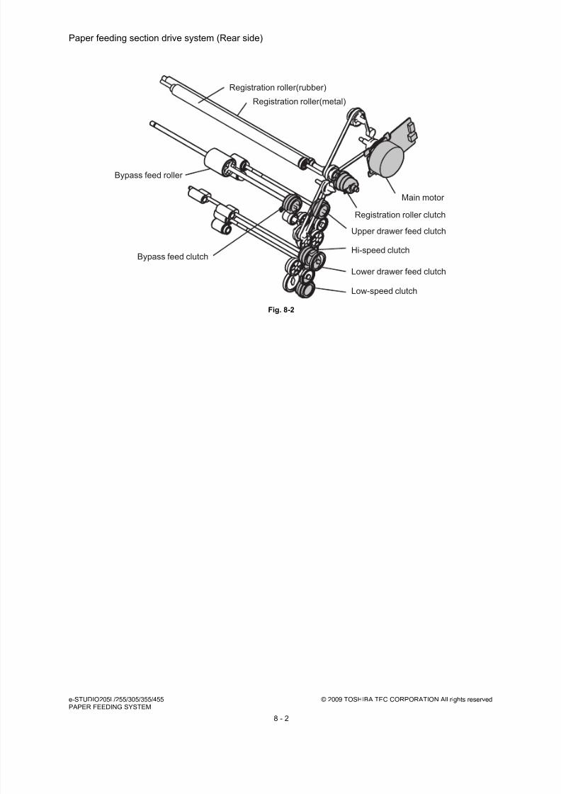
8/17/2019 Toshiba ES455 Service Manual
http://slidepdf.com/reader/full/toshiba-es455-service-manual 178/335
e-STUDIO205L/255/305/355/455 © 2009 TOSHIBA TEC CORPORATION All rights reservedPAPER FEEDING SYSTEM
8 - 2
Paper feeding section drive system (Rear side)
Fig. 8-2
Registration roller(metal)
Registration roller(rubber)
Main motor
Registration roller clutch
Hi-speed clutch
Low-speed clutch
Bypass feed roller
Bypass feed clutch
Upper drawer feed clutch
Lower drawer feed clutch

8/17/2019 Toshiba ES455 Service Manual
http://slidepdf.com/reader/full/toshiba-es455-service-manual 179/335
© 2009 TOSHIBA TEC CORPORATION All rights reserved e-STUDIO205L/255/305/355/455PAPER FEEDING SYSTEM
8 - 3
8.2 Composition
Paper feed
Upper/Lower drawer feed unit Upper/Lower drawer pickup roller PM parts
Upper/Lower drawer feed roller PM parts
Upper/Lower drawer separation roller PM parts
Upper/Lower drawer paper stock sensor S15/S18
Upper/Lower drawer tray-up sensor S16/S19
Upper/Lower drawer empty sensor S17/S20
Upper/Lower drawer feed clutch CLT4/CLT5
Bypass unit Bypass feed roller PM parts
Bypass separation pad PM parts
Bypass paper sensor S12
Bypass feed clutch CLT3
Paper width detection PC board SFB
Transport section, other Upper/Lower drawer tray-up motor M11/M12
Upper/Lower drawer detection switch SW7/SW8
Registration sensor S22
Registration roller (rubber)
Registration roller (metal)
1st/2nd transport sensor S21/S14
Transport roller
Registration roller clutch CLT2
Hi-speed clutch CLT6
Low-speed clutch CLT7
Feed cover opening/closing detectionsensor
S13

8/17/2019 Toshiba ES455 Service Manual
http://slidepdf.com/reader/full/toshiba-es455-service-manual 180/335
e-STUDIO205L/255/305/355/455 © 2009 TOSHIBA TEC CORPORATION All rights reservedPAPER FEEDING SYSTEM
8 - 4
8.3 Functions
1. Pickup roller
This roller moves up and down to draw out a sheet of paper from the drawer, and transport it to the
feed roller.
2. Feed roller
This roller transports the paper from the pickup roller to the registration roller.
3. Separation roller
This roller is mounted against the feed roller. When two sheets of paper or more are transported
from the pickup roller, the load of the torque limiter (spring) of the separation roller is greater than the
frictional force between the sheets. As the result, the separation roller is stopped and the lower
sheet of paper is not transported any further. When only one sheet of paper is transported from the
pickup roller, the separation roller is forced to rotate following the feed roller.
4. Transport roller
This roller transports the paper from the lower drawer or PFP/LCF to the 1st transport roller.
5. Registration roller
Paper transported from the 1st transport roller is pushed against the registration rollers, which aligns
the leading edge of paper. The registration roller then rotates to transport the paper to the transfersection.
6. Bypass feed roller
This roller picks up and feeds paper from the bypass unit.
7. Bypass separation pad
This pad is located under the bypass feed roller and pressed to this roller with spring force. This pad
prevents more than one sheet of paper from being fed simultaneously with its frictional surface.
8. Bypass paper sensor(S12)
This sensor detects whether paper is set in the bypass tray or not. If it is, bypass feeding is
performed in preference to drawer feeding. And also detects whether paper has been transportedfrom the bypass tray or not. In other words, whether the leading/trailing edge of paper has passed
the feed sensor or not. This sensor is utilized to detect the jams such as paper misfeeding in the
bypass unit.
9. Upper/Lower drawer empty sensor (S17/S20)
This is a transmissive-type sensor which detects the presence/absence of paper in the drawer using
an actuator. When there is no paper in the drawer, the actuator blocks the light path of the sensor.
Then the sensor determines that there is no paper.
10.Upper/Lower drawer paper stock sensor (S15/S18)
This is a transmissive-type sensor which detects the amount of paper remaining in the drawer using
an actuator. When the remaining paper has become around 100 sheets, the actuator blocks the light
path of the sensor to notify that the paper quantity is getting less.
11.Registration sensor (S22)
This sensor detects whether the leading edge of the paper has reached the registration roller or not,
and the trailing edge of paper has passed the registration roller or not.
12.1st transport sensor sensor (S21)
This sensor detects whether paper from each paper source is being transported or not.
8/17/2019 Toshiba ES455 Service Manual
http://slidepdf.com/reader/full/toshiba-es455-service-manual 181/335
© 2009 TOSHIBA TEC CORPORATION All rights reserved e-STUDIO205L/255/305/355/455PAPER FEEDING SYSTEM
8 - 5
13.2nd transport sensor (S14)
This sensor detects whether paper from the lower drawer, PFP or LCF (both optional) is being
transported or not.
14.Upper/Lower drawer feed clutch (CLT4/CLT5)
These clutches drive the upper and lower drawer pickup rollers. When these clutches are turned ON
while the main motor (M8) is being rotated, the drive from these clutches rotates the pickup rollers
so as to pick up paper.
15.Hi-speed clutch (CLT6)Drives the Transport roller at high speed by transmitting the drive from the main motor.
16.Low-speed clutch (CLT7)
Drives the Transport roller at low speed by transmitting the drive from the main motor.
17.Registration roller clutch (CLT2)
Drives the registration roller.
18.Bypass feed clutch (CLT3)
This clutch drives the rotation of the bypass feed roller. When this clutch is turned ON while the main
motor (M8) is being rotated, the drive from this clutch feeds and transports paper on the bypass tray
to the inside of this equipment.

8/17/2019 Toshiba ES455 Service Manual
http://slidepdf.com/reader/full/toshiba-es455-service-manual 182/335
e-STUDIO205L/255/305/355/455 © 2009 TOSHIBA TEC CORPORATION All rights reservedPAPER FEEDING SYSTEM
8 - 6
8.4 Operation
8.4.1 Bypass feeding mechanism
Paper on the bypass tray becomes ready for being fed when the paper holding lever is laid down to a
side on which paper is placed (the equipment side).
When the paper holding lever is laid down to the equipment side, the paper holding guide lifts up the
paper as shown in the figure so as to contact the paper with the bypass feed roller.
Then the paper is fed along with the rotation of the bypass feed roller.
The bypass separation pad prevents more than one sheet of paper from being fed simultaneously.
Fig. 8-3
Paper holding lever
Paper
Bypass feed roller
(Bypass feed clucth)
Separation padPaper holding guide

8/17/2019 Toshiba ES455 Service Manual
http://slidepdf.com/reader/full/toshiba-es455-service-manual 183/335
© 2009 TOSHIBA TEC CORPORATION All rights reserved e-STUDIO205L/255/305/355/455PAPER FEEDING SYSTEM
8 - 7
8.4.2 Operation of drawer pickup roller
When the drawer is inserted, the pickup roller and roller holder fall by the trayup motor driving force.
Then the drawer tray lifts up and paper feeding is enabled.
When the drawer feed clutch is turned ON, the drive from the main motor is transmitted. Then the feed
roller and pickup roller rotate to transport the paper from the drawer.
The separation roller under the feed roller prevents multiple transporting of paper.
Fig. 8-4
Drawer feed clutch
Feed roller
Separation
roller
Pickup roller

8/17/2019 Toshiba ES455 Service Manual
http://slidepdf.com/reader/full/toshiba-es455-service-manual 184/335
e-STUDIO205L/255/305/355/455 © 2009 TOSHIBA TEC CORPORATION All rights reservedPAPER FEEDING SYSTEM
8 - 8
8.4.3 Separation of paper
The separation roller in this equipment works to
separate the sheets of paper being fed. The
separation roller section consists of the feed
roller, separation roller, spring joint, etc. The feed
roller rotates in the direction of the white arrow
(shown below in the figure at right) at the same
timing as the pickup roller rotation when the feedclutch is turned ON.
Fig. 8-5
When two sheets of paper are transported
(shown in the figure at right), the lower sheet is
braked by the separation roller and not
transported any further and the upper sheet is
transported in the direction of black arrow sincethe frictional force between two sheets is small.
(Example)
When only one sheet enters into the separation
roller section:
Since the transporting force of the feed roller is
greater than the braking force of the separation
roller, these two rollers rotate together to
transport the sheet to the registration roller.
When two sheets enter into the separation roller
section:Since the transporting force of the feed roller and
the breaking force of the separation roller are
greater than the frictional force between two
sheets, the sheet A is transported in the direction
of the black arrow and the sheet B is braked by
the separation roller and is not transported any
further.
Fig. 8-6
Feed roller
Spring joint
Separation roller
Feed roller
Separation roller

8/17/2019 Toshiba ES455 Service Manual
http://slidepdf.com/reader/full/toshiba-es455-service-manual 185/335

8/17/2019 Toshiba ES455 Service Manual
http://slidepdf.com/reader/full/toshiba-es455-service-manual 186/335
e-STUDIO205L/255/305/355/455 © 2009 TOSHIBA TEC CORPORATION All rights reservedPAPER FEEDING SYSTEM
8 - 10
8.4.5 General operation
[A] From power-ON to ready status
• When the equipment is turned ON, the tray-up motor starts to rotate forward and the upper/lower
drawer trays starts to rise. When the tray has risen and the tray-up sensor is turned ON, the tray-
up motor is turned OFF, then the tray stops to rising. At this time, if the empty sensor is OFF, it is
judged that there is no paper in the drawer. If the empty sensor is ON, there is paper in the
drawer. The tray stops at raised position regardless of the presence/absence of paper.
• If the drawer is not completely inserted when the equipment is turned ON, the tray in that drawer
does not rise. When the drawer is inserted completely, the tray is raised and checks the
presence/absence of paper.
• If either of the feed sensors is ON (= there is paper on the transport path) at power-ON, it is
determined that a paper jam has occurred and no operation is enabled until the jammed paper is
removed.
[B] Ready status
• After the tray is moved up to check the presence/absence of paper as described above, the
equipment enters the ready state. During the ready mode, the tray stays at the raised position.
• When a drawer is inserted or removed in the ready state, the tray is raised again and checks the
presence/absence of paper.
[C] Bypass feeding
• The bypass feed sensor detects the passing of paper.
• The bypass feed clutch is turned ON, and the bypass feed roller is rotated to start feeding.
• Paper feeding is started and the bypass feed sensor detects the passing of paper.
• TThe leading edge of the paper turns the registration sensor ON, and the paper is aligned withthe registration rollers.
• The bypass feed clutch is turned OFF, and the bypass feed roller is stopped.
• The registration clutch is turned ON, and the paper is transported to the transfer unit.
[D] Paper feeding
• Lower drawer
- The feed clutch and high speed clutch is turned ON, and the pickup roller, feed roller and
transport roller rotate to start paper feeding.
- The leading edge of paper turns the 1st transport sensor ON, and the feed clutch is turned
OFF. (Pick-up roller and feed roller stop rotating.)
- The leading edge of paper turns the registration sensor ON and the paper is aligned by the
registration rollers.
- The high speed clutch is turned OFF, and the transport roller stop rotating.
- The registration roller clutch and low speed clutch are turned ON, and the paper is
transported to the transfer unit.

8/17/2019 Toshiba ES455 Service Manual
http://slidepdf.com/reader/full/toshiba-es455-service-manual 187/335
© 2009 TOSHIBA TEC CORPORATION All rights reserved e-STUDIO205L/255/305/355/455PAPER FEEDING SYSTEM
8 - 11
• Upper drawer
- The feed clutch is turned ON and the pickup roller and feed roller rotate to start paper feeding.
- The leading edge of paper turns the registration sensor ON, and the paper is aligned by the
registration rollers.
- The feed clutch is turned OFF and the pickup roller and feed roller to stop rotating.
- The registration roller clutch is turned ON, and the paper is transported to the transfer unit.
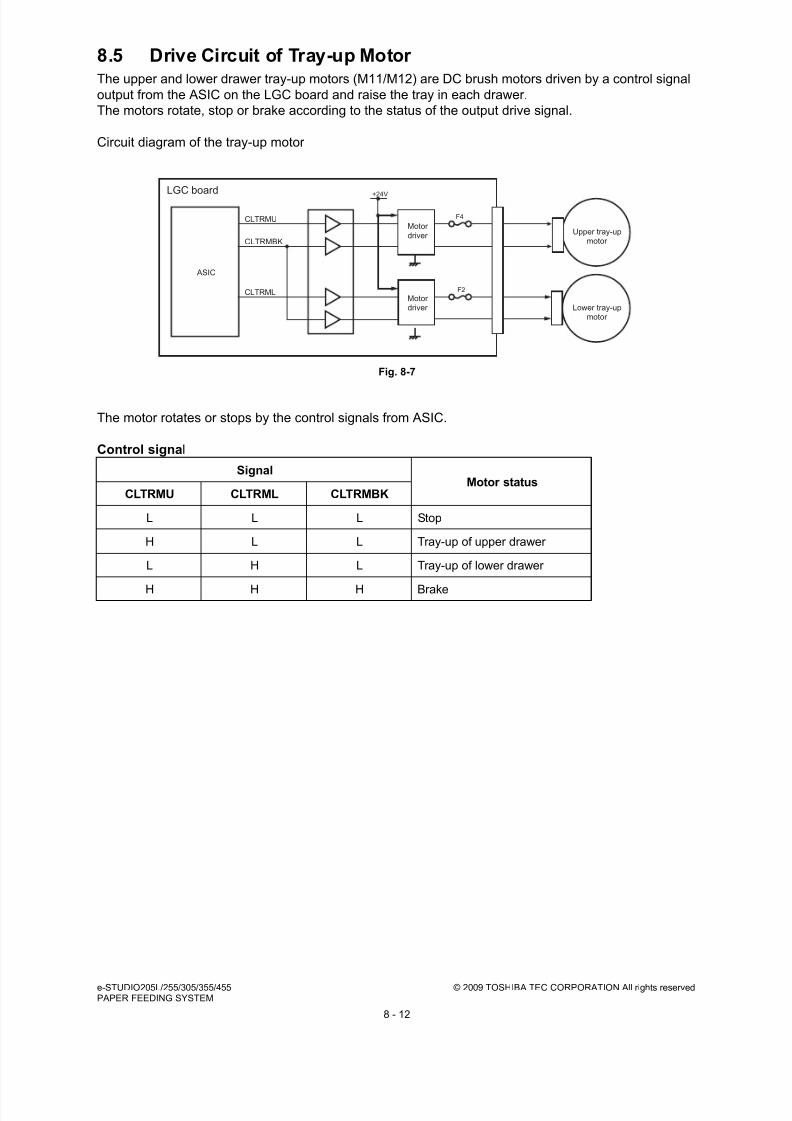
8/17/2019 Toshiba ES455 Service Manual
http://slidepdf.com/reader/full/toshiba-es455-service-manual 188/335
e-STUDIO205L/255/305/355/455 © 2009 TOSHIBA TEC CORPORATION All rights reservedPAPER FEEDING SYSTEM
8 - 12
8.5 Drive Circuit of Tray-up Motor The upper and lower drawer tray-up motors (M11/M12) are DC brush motors driven by a control signal
output from the ASIC on the LGC board and raise the tray in each drawer.
The motors rotate, stop or brake according to the status of the output drive signal.
Circuit diagram of the tray-up motor
Fig. 8-7
The motor rotates or stops by the control signals from ASIC.
Control signal
SignalMotor status
CLTRMU CLTRML CLTRMBK
L L L Stop
H L L Tray-up of upper drawer
L H L Tray-up of lower drawer
H H H Brake
ASIC
+24V
CLTRMBK
CLTRMU
CLTRML
Motor
driver
F4
F2
Upper tray-upmotor
LGC board
Lower tray-upmotor
Motor driver

8/17/2019 Toshiba ES455 Service Manual
http://slidepdf.com/reader/full/toshiba-es455-service-manual 189/335
© 2009 TOSHIBA TEC CORPORATION All rights reserved e-STUDIO205L/255/305/355/455PAPER FEEDING SYSTEM
8 - 13
8.6 Disassembly and Replacement
8.6.1 Drawer
8.6.2 Drawer feeding unit
(1) Pull out the drawer until it comes to a stop.
(2) Remove 1 screw and the stopper.
(3) Take off the drawer.
Fig. 8-8
(1) Take off the drawer.
( P.8-13 "8.6.1 Drawer").
(2) Open the feed cover.
(3) Remove 1 screw and take off the drawer
feeding unit by sliding it to the front side.
Fig. 8-9
Stopper
Drawer feeding unit
Feed cover

8/17/2019 Toshiba ES455 Service Manual
http://slidepdf.com/reader/full/toshiba-es455-service-manual 190/335
e-STUDIO205L/255/305/355/455 © 2009 TOSHIBA TEC CORPORATION All rights reservedPAPER FEEDING SYSTEM
8 - 14
8.6.3 Tray-up sensor (S16/S19)
8.6.4 Empty sensor (S17/S20)
(1) Take off the drawer feeding unit
( P.8-13 "8.6.2 Drawer feeding unit").
(2) Disconnect the connector and release the 3
latches to take off the tray-up sensor.
Fig. 8-10
(1) Take off the drawer feeding unit
( P.8-13 "8.6.2 Drawer feeding unit").
(2) Remove 1 screw and then slide the guide
slightly.
Fig. 8-11
(3) Disconnect 1 connector and then take off the
upper/lower drawer empty sensor by
releasing 3 latches.
Fig. 8-12
Tray-up sensor
Guide
Empty sensor

8/17/2019 Toshiba ES455 Service Manual
http://slidepdf.com/reader/full/toshiba-es455-service-manual 191/335
© 2009 TOSHIBA TEC CORPORATION All rights reserved e-STUDIO205L/255/305/355/455PAPER FEEDING SYSTEM
8 - 15
8.6.5 Paper stock sensor (S15/S18)
8.6.6 Separation roller
(1) Take off the drawer feeding unit
( P.8-13 "8.6.2 Drawer feeding unit").
(2) Pull up the paper stock sensor arm.
(3) Disconnect the connector and release the 3
latches to take off the paper stock sensor.
Fig. 8-13
(1) Take off the drawer feeding unit( P.8-13 "8.6.2 Drawer feeding unit").
(2) Remove 1 screw and take off the separation
roller holder.
Fig. 8-14
(3) Detach the lever from the holder and take off
the separation roller with the shaft.
Fig. 8-15
Paper stock sensor
Separation roller holder
Lever
Separation roller

8/17/2019 Toshiba ES455 Service Manual
http://slidepdf.com/reader/full/toshiba-es455-service-manual 192/335
e-STUDIO205L/255/305/355/455 © 2009 TOSHIBA TEC CORPORATION All rights reservedPAPER FEEDING SYSTEM
8 - 16
8.6.7 Feed roller
8.6.8 Pickup roller
(4) Detach the cover, arbor and clutch spring
from the shaft, and then take off the
separation roller.
Fig. 8-16
(1) Take off the separation roller holder
( P.8-15 "8.6.6 Separation roller").
(2) Remove the clip and take off the feed roller.
Fig. 8-17
(1) Take off the drawer feeding unit
( P.8-13 "8.6.2 Drawer feeding unit").
(2) Remove the pickup roller assembly from the
pickup arms. Take off the timing belt and
then take off the pickup roller assembly.
Fig. 8-18
Arbor
Arbor
Cover
Clutch spring
Separation roller
Shaft
Clip
Feed roller
One-way clutch
Pickup roller assembly
Timing belt
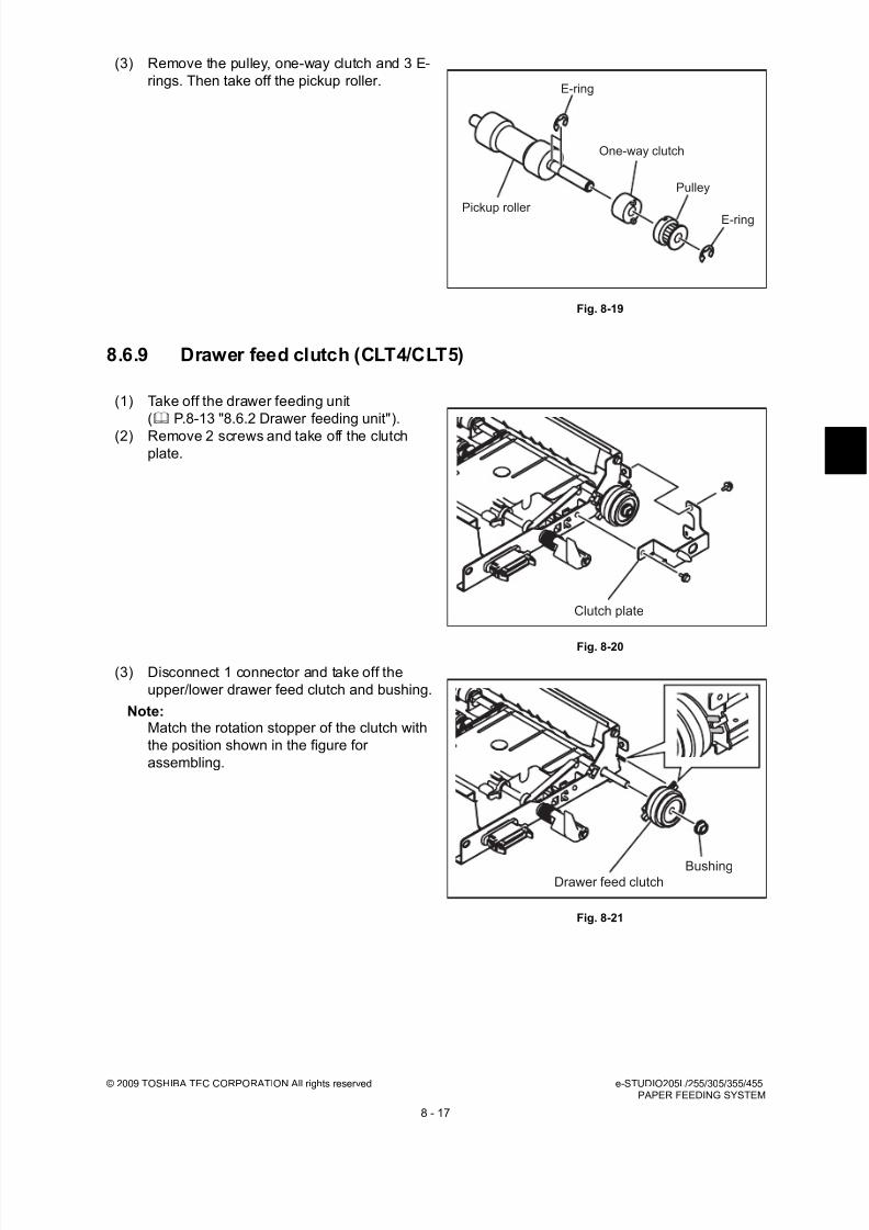
8/17/2019 Toshiba ES455 Service Manual
http://slidepdf.com/reader/full/toshiba-es455-service-manual 193/335
© 2009 TOSHIBA TEC CORPORATION All rights reserved e-STUDIO205L/255/305/355/455PAPER FEEDING SYSTEM
8 - 17
8.6.9 Drawer feed clutch (CLT4/CLT5)
(3) Remove the pulley, one-way clutch and 3 E-
rings. Then take off the pickup roller.
Fig. 8-19
(1) Take off the drawer feeding unit
( P.8-13 "8.6.2 Drawer feeding unit").
(2) Remove 2 screws and take off the clutchplate.
Fig. 8-20
(3) Disconnect 1 connector and take off the
upper/lower drawer feed clutch and bushing.
Note:Match the rotation stopper of the clutch with
the position shown in the figure for
assembling.
Fig. 8-21
E-ring
One-way clutch
Pickup roller
Pulley
E-ring
Clutch plate
Drawer feed clutchBushing
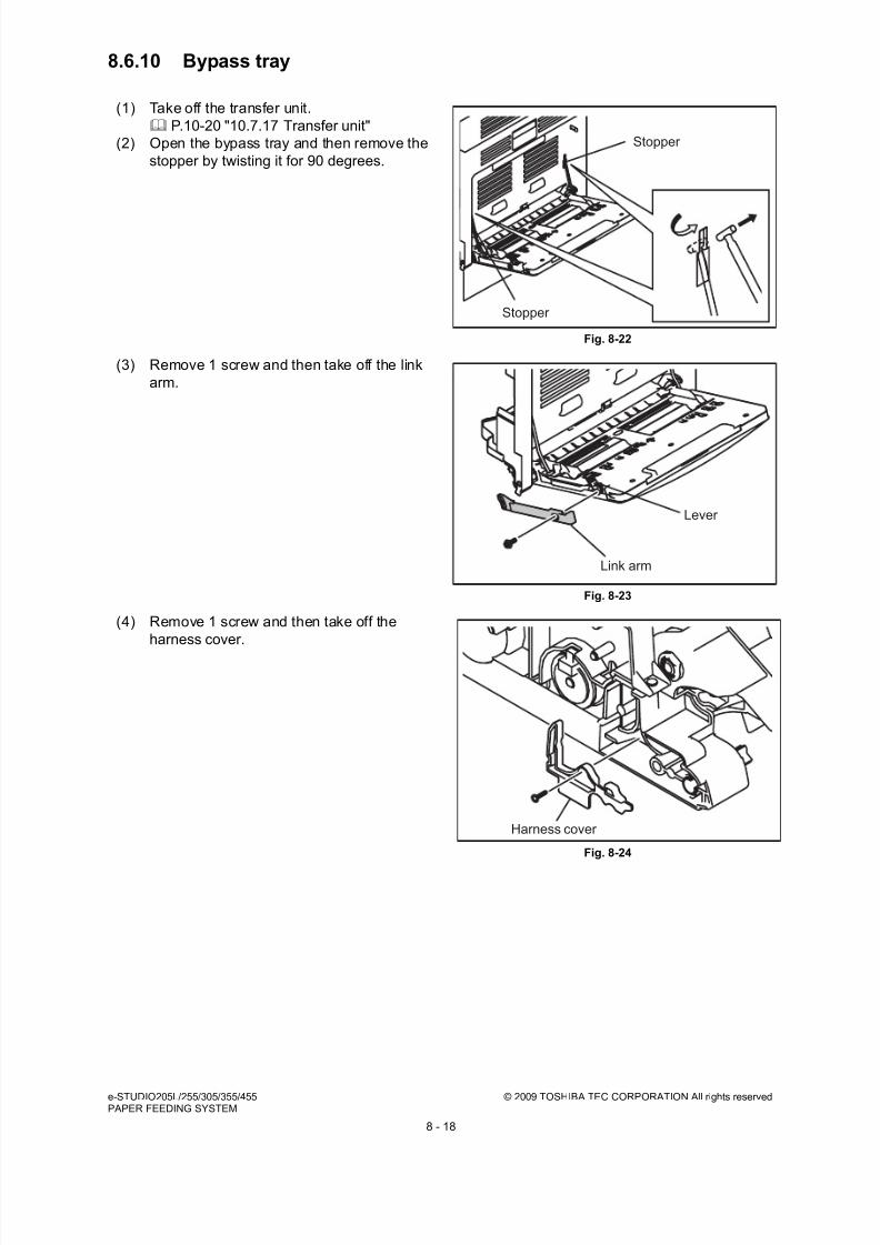
8/17/2019 Toshiba ES455 Service Manual
http://slidepdf.com/reader/full/toshiba-es455-service-manual 194/335
e-STUDIO205L/255/305/355/455 © 2009 TOSHIBA TEC CORPORATION All rights reservedPAPER FEEDING SYSTEM
8 - 18
8.6.10 Bypass tray
(1) Take off the transfer unit.
P.10-20 "10.7.17 Transfer unit"
(2) Open the bypass tray and then remove the
stopper by twisting it for 90 degrees.
Fig. 8-22
(3) Remove 1 screw and then take off the link
arm.
Fig. 8-23
(4) Remove 1 screw and then take off the
harness cover.
Fig. 8-24
Stopper
Stopper
Lever
Link arm
Harness cover

8/17/2019 Toshiba ES455 Service Manual
http://slidepdf.com/reader/full/toshiba-es455-service-manual 195/335
© 2009 TOSHIBA TEC CORPORATION All rights reserved e-STUDIO205L/255/305/355/455PAPER FEEDING SYSTEM
8 - 19
8.6.11 Paper width detection PC board (SFB)
(5) Disconnect 1 connector and then take off the
bypass tray downward obliquely.
Fig. 8-25
(1) Take off the bypass tray.
( P.8-18 "8.6.10 Bypass tray").
(2) Remove 3 screws and take off the bypass
tray upper cover.
Fig. 8-26
(3) Remove 1 screw and then take off the
sensor cover by releasing 3 hooks.
Fig. 8-27
Bypass tray
Bypass tray upper cover
Sensor cover

8/17/2019 Toshiba ES455 Service Manual
http://slidepdf.com/reader/full/toshiba-es455-service-manual 196/335
e-STUDIO205L/255/305/355/455 © 2009 TOSHIBA TEC CORPORATION All rights reservedPAPER FEEDING SYSTEM
8 - 20
8.6.12 Bypass feed unit
(4) Disconnect 1 connector and then take off the
paper width detection PC board.
Fig. 8-28
(1) Take off the automatic duplexing unit.
P.14-9 "14.5.1 Automatic Duplexing Unit
(ADU)"(2) Release 2 latches and then take off the
spring holder.
Fig. 8-29
(3) Disconnect 1 connector and remove 2
screws. Then take off the bypass feed unit.
Fig. 8-30
Paper size detection board
Spring hplder
Bypass feed unit

8/17/2019 Toshiba ES455 Service Manual
http://slidepdf.com/reader/full/toshiba-es455-service-manual 197/335
© 2009 TOSHIBA TEC CORPORATION All rights reserved e-STUDIO205L/255/305/355/455PAPER FEEDING SYSTEM
8 - 21
8.6.13 Bypass separation pad
8.6.14 Bypass feed roller /Bypass feed clutch (CLT3)
(1) Take off the bypass feed unit
( P.8-20 "8.6.12 Bypass feed unit").
(2) Remove 1 clip and then slide the bypass
feed roller.
Fig. 8-31
(3) Take off the bypass separation pad (arm).
Fig. 8-32
(1) Take off the bypass feed unit
( P.8-20 "8.6.12 Bypass feed unit").
(2) Remove 1 clip.
Fig. 8-33
Clip
Bypass feed roller
Arm
Bypass separation pad
Clip

8/17/2019 Toshiba ES455 Service Manual
http://slidepdf.com/reader/full/toshiba-es455-service-manual 198/335
e-STUDIO205L/255/305/355/455 © 2009 TOSHIBA TEC CORPORATION All rights reservedPAPER FEEDING SYSTEM
8 - 22
8.6.15 Bypass paper sensor (S12)
(3) Take off the shaft by sliding it.
Note:When installing the bypass feed clutch, be
sure that the rotation stopper is inserted in
the hole of the guide securely.
Fig. 8-34
(4) Remove 1 clip and 2 bushings. Then take off
the bypass feed roller and the bypass feed
clutch.
Fig. 8-35
(1) Take off the bypass feed unit
( P.8-20 "8.6.12 Bypass feed unit").
(2) Disconnect 1 connector and then take off the
bypass paper sensor by releasing 3 latches.
Fig. 8-36
Shaft
Shaft
Bypass feed roller
Bypass feed clutch
Clip
Bypass paper sensor
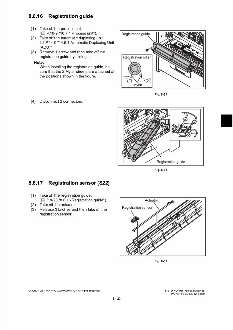
8/17/2019 Toshiba ES455 Service Manual
http://slidepdf.com/reader/full/toshiba-es455-service-manual 199/335
© 2009 TOSHIBA TEC CORPORATION All rights reserved e-STUDIO205L/255/305/355/455PAPER FEEDING SYSTEM
8 - 23
8.6.16 Registration guide
8.6.17 Registration sensor (S22)
(1) Take off the process unit.
( P.10-9 "10.7.1 Process unit").
(2) Take off the automatic duplexing unit.
P.14-9 "14.5.1 Automatic Duplexing Unit
(ADU)"
(3) Remove 1 screw and then take off the
registration guide by sliding it.Note:
When installing the registration guide, be
sure that the 2 Mylar sheets are attached at
the positions shown in the figure.
Fig. 8-37
(4) Disconnect 2 connectors.
Fig. 8-38
(1) Take off the registration guide.
( P.8-23 "8.6.16 Registration guide").
(2) Take off the actuator.
(3) Release 3 latches and then take off the
registration sensor.
Fig. 8-39
Registration guide
Registration roller
Mylar
Registration guide
Registration sensor
Actuator

8/17/2019 Toshiba ES455 Service Manual
http://slidepdf.com/reader/full/toshiba-es455-service-manual 200/335
e-STUDIO205L/255/305/355/455 © 2009 TOSHIBA TEC CORPORATION All rights reservedPAPER FEEDING SYSTEM
8 - 24
8.6.18 1st transport sensor (S21))
8.6.19 Feed cover
(1) Take off the registration guide.
( P.8-23 "8.6.16 Registration guide").
(2) Take off the actuator.
(3) Release 3 latches and then take off the 1st
transport sensor.
Fig. 8-40
(1) Open the feed cover and then pull out the
locking pin.
Fig. 8-41
(2) Take off the feed cover by sliding it.
Fig. 8-42
1st transport sensor
Actuator
Locking pin
Feed cover

8/17/2019 Toshiba ES455 Service Manual
http://slidepdf.com/reader/full/toshiba-es455-service-manual 201/335
© 2009 TOSHIBA TEC CORPORATION All rights reserved e-STUDIO205L/255/305/355/455PAPER FEEDING SYSTEM
8 - 25
8.6.20 Transport roller
(1) Take off the right front cover.
P.2-25 "2.5.14 Right front cover"
(2) Take off the high-speed clutch.
( P.8-29 "8.6.27 Hi-speed clutch (CLT6) /
Low-speed clutch(CLT7)").
(3) Take off the feed cover.
( P.8-24 "8.6.19 Feed cover").(4) Remove 2 screws and then take off the stay.
Fig. 8-43
(5) Remove 1 screw and then slide the paper
guide B to the rear side.
(6) Disconnect 2 connectors and then take off
the paper guide B.
Fig. 8-44
(7) Remove 1 clip, 1 E-ring, and then take off thetransport roller.
Fig. 8-45
Stay
Paper guide B
Clip
Transport roller
Bushing
Bushing

8/17/2019 Toshiba ES455 Service Manual
http://slidepdf.com/reader/full/toshiba-es455-service-manual 202/335
e-STUDIO205L/255/305/355/455 © 2009 TOSHIBA TEC CORPORATION All rights reservedPAPER FEEDING SYSTEM
8 - 26
8.6.21 2nd transport sensor (S14)
8.6.22 Feed cover opening/closing detection sensor (S13)
8.6.23 Flywheel
(1) Take off the transport roller.
( P.8-25 "8.6.20 Transport roller").
(2) Take off the actuator.
(3) Release 3 latches and then take off the 2nd
transport sensor.
Fig. 8-46
(1) Take off the transport roller.
( P.8-25 "8.6.20 Transport roller").
(2) Release 3 latches and then take off the feed
cover opening/closing sensor.
Fig. 8-47
(1) Take off the rear cover.
P.2-22 "2.5.6 Rear cover"
(2) Remove 1 screw and then remove 4
flywheels.
Fig. 8-48
Actuator
2nd transport sensor
Feed cover sensor
Flywheel

8/17/2019 Toshiba ES455 Service Manual
http://slidepdf.com/reader/full/toshiba-es455-service-manual 203/335
© 2009 TOSHIBA TEC CORPORATION All rights reserved e-STUDIO205L/255/305/355/455PAPER FEEDING SYSTEM
8 - 27
8.6.24 Registration roller clutch (CLT2)
8.6.25 Upper tray-up motor (M11)
(1) Take off the flywheel.
P.8-26 "8.6.23 Flywheel"
(2) Remove 2 screws and then take off the
clutch cover.
Note:Match the rotation stopper of the clutch with
the position shown in the figure forassembling.
Fig. 8-49
(3) Disconnect 1 connector and then take off the
registration roller clutch.
Fig. 8-50
(1) Pull out the upper drawer.
(2) Take off the rear cover.
P.2-22 "2.5.6 Rear cover"
(3) Remove 3 screws and then take off the tray-
up gear unit.
Fig. 8-51
Clutch cover
Registration roller clutch
Tray-up gear unit

8/17/2019 Toshiba ES455 Service Manual
http://slidepdf.com/reader/full/toshiba-es455-service-manual 204/335
e-STUDIO205L/255/305/355/455 © 2009 TOSHIBA TEC CORPORATION All rights reservedPAPER FEEDING SYSTEM
8 - 28
8.6.26 Upper drawer detection switch (SW7)
(4) Remove 1 clip and 1 gear.
Fig. 8-52
(5) Disconnect 1 connector and then remove 2
screws. Then take off the upper tray-up
motor.
Fig. 8-53
(1) Pull out the upper drawer.
(2) Take off the rear cover.
P.2-22 "2.5.6 Rear cover"
(3) Disconnect 1 connector and then take off the
upper drawer detection switch.
Fig. 8-54
Gear
Clip
Upper drawer tray-up motor
Upper drawer detection switch

8/17/2019 Toshiba ES455 Service Manual
http://slidepdf.com/reader/full/toshiba-es455-service-manual 205/335
© 2009 TOSHIBA TEC CORPORATION All rights reserved e-STUDIO205L/255/305/355/455PAPER FEEDING SYSTEM
8 - 29
8.6.27 Hi-speed clutch (CLT6) / Low-speed clutch(CLT7)
(1) Take off the rear cover.
P.2-22 "2.5.6 Rear cover"
(2) Remove 1 clip and then take off the bushing.
Fig. 8-55
(3) Remove 3 screws and then take off the
bracket.
Fig. 8-56
(4) Disconnect 1 connector and then take off thelow-speed clutch.
Note:Match the rotation stopper of the clutch with
the position shown in the figure for
assembling.
Fig. 8-57
Bushing
Clip
Bracket
Low-speed clutch
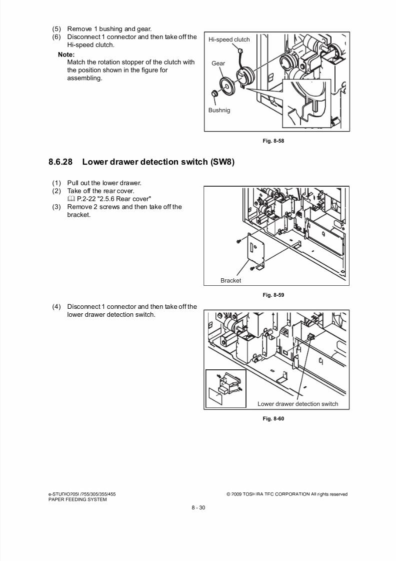
8/17/2019 Toshiba ES455 Service Manual
http://slidepdf.com/reader/full/toshiba-es455-service-manual 206/335
e-STUDIO205L/255/305/355/455 © 2009 TOSHIBA TEC CORPORATION All rights reservedPAPER FEEDING SYSTEM
8 - 30
8.6.28 Lower drawer detection switch (SW8)
(5) Remove 1 bushing and gear.
(6) Disconnect 1 connector and then take off the
Hi-speed clutch.
Note:Match the rotation stopper of the clutch with
the position shown in the figure for
assembling.
Fig. 8-58
(1) Pull out the lower drawer.
(2) Take off the rear cover.
P.2-22 "2.5.6 Rear cover"(3) Remove 2 screws and then take off the
bracket.
Fig. 8-59
(4) Disconnect 1 connector and then take off the
lower drawer detection switch.
Fig. 8-60
Hi-speed clutch
Gear
Bushnig
Bracket
Lower drawer detection switch
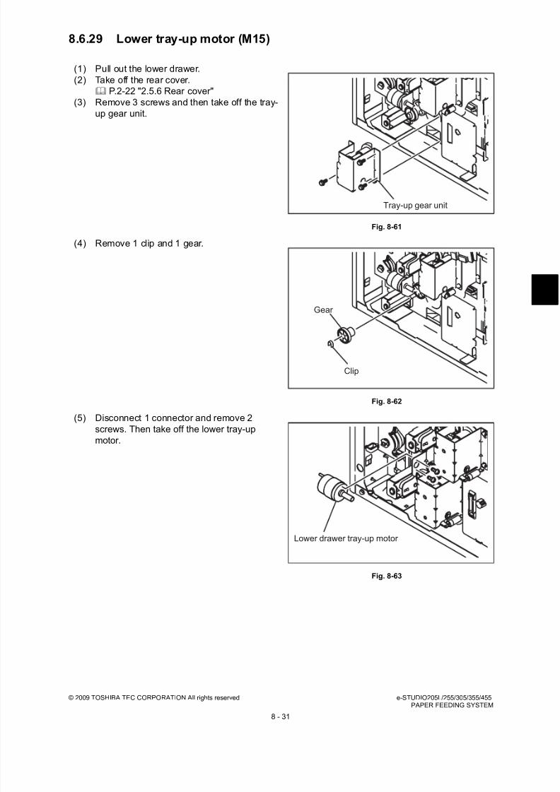
8/17/2019 Toshiba ES455 Service Manual
http://slidepdf.com/reader/full/toshiba-es455-service-manual 207/335
© 2009 TOSHIBA TEC CORPORATION All rights reserved e-STUDIO205L/255/305/355/455PAPER FEEDING SYSTEM
8 - 31
8.6.29 Lower tray-up motor (M15)
(1) Pull out the lower drawer.
(2) Take off the rear cover.
P.2-22 "2.5.6 Rear cover"
(3) Remove 3 screws and then take off the tray-
up gear unit.
Fig. 8-61
(4) Remove 1 clip and 1 gear.
Fig. 8-62
(5) Disconnect 1 connector and remove 2screws. Then take off the lower tray-up
motor.
Fig. 8-63
Tray-up gear unit
Gear
Clip
Lower drawer tray-up motor

8/17/2019 Toshiba ES455 Service Manual
http://slidepdf.com/reader/full/toshiba-es455-service-manual 208/335
e-STUDIO205L/255/305/355/455 © 2009 TOSHIBA TEC CORPORATION All rights reservedPAPER FEEDING SYSTEM
8 - 32
8.6.30 Registration roller (rubber)
(1) Take off the transfer unit
P.10-20 "10.7.17 Transfer unit"
(2) Remove 1 screw and then take off the
bracket while holding the registration roller.
Fig. 8-64
(3) Lift up the rear side of the registration roller
and then pull out the roller to the rear side.
Fig. 8-65
(4) Take off 2 guide rollers. Then remove 1 E-ring and 1 gear.
Fig. 8-66
Bracket
Registration roller (rubber)
Washer
Washer
E-ring
Pin
Gear

8/17/2019 Toshiba ES455 Service Manual
http://slidepdf.com/reader/full/toshiba-es455-service-manual 209/335
© 2009 TOSHIBA TEC CORPORATION All rights reserved e-STUDIO205L/255/305/355/455PAPER FEEDING SYSTEM
8 - 33
8.6.31 Registration roller (metal)
(1) Take off the process unit
P.10-9 "10.7.1 Process unit"
(2) Take off the automatic duplexing unit.
P.14-9 "14.5.1 Automatic Duplexing Unit
(ADU)"
(3) Take off the registration roller clutch.
P.8-27 "8.6.24 Registration roller clutch(CLT2)"
(4) Remove 1 clip on the rear side.
Fig. 8-67
(5) Take off the registration roller (metal) by
sliding it to the rear side and pulling it out
toward you.
Fig. 8-68
Clip
Registration roller (metal)

8/17/2019 Toshiba ES455 Service Manual
http://slidepdf.com/reader/full/toshiba-es455-service-manual 210/335
e-STUDIO205L/255/305/355/455 © 2009 TOSHIBA TEC CORPORATION All rights reservedPAPER FEEDING SYSTEM
8 - 34
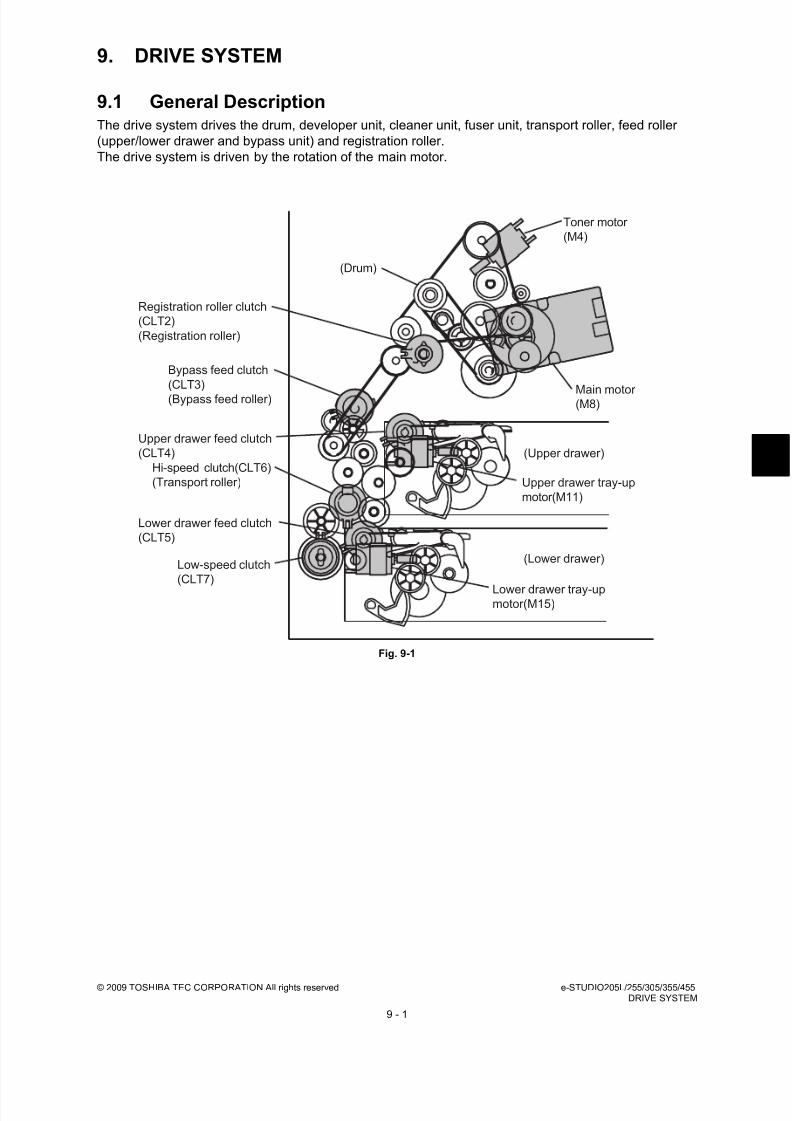
8/17/2019 Toshiba ES455 Service Manual
http://slidepdf.com/reader/full/toshiba-es455-service-manual 211/335
© 2009 TOSHIBA TEC CORPORATION All rights reserved e-STUDIO205L/255/305/355/455DRIVE SYSTEM
9 - 1
9. DRIVE SYSTEM
9.1 General DescriptionThe drive system drives the drum, developer unit, cleaner unit, fuser unit, transport roller, feed roller
(upper/lower drawer and bypass unit) and registration roller.
The drive system is driven by the rotation of the main motor.
Fig. 9-1
Main motor (M8)
Toner motor
(M4)
Registration roller clutch
(CLT2)
(Registration roller)
Bypass feed clutch
(CLT3)
(Bypass feed roller)
Upper drawer feed clutch
(CLT4)
Lower drawer tray-upmotor(M15)
Upper drawer tray-up
motor(M11)
Lower drawer feed clutch
(CLT5)
Hi-speed clutch(CLT6)
(Transport roller)
Low-speed clutch
(CLT7)
(Drum)
(Upper drawer)
(Lower drawer)
8/17/2019 Toshiba ES455 Service Manual
http://slidepdf.com/reader/full/toshiba-es455-service-manual 212/335
e-STUDIO205L/255/305/355/455 © 2009 TOSHIBA TEC CORPORATION All rights reservedDRIVE SYSTEM
9 - 2
9.2 Functions
1. Drum cleaner unit drive
Drives the drum by transmitting the rotation of the main motor through the gears and the timing belt
to the drum flange gear. Also drives the toner recovery auger to transport the used toner to the
developer unit.
2. Developer unit drive
Drives the developer unit by transmitting the rotation of the main motor through the gears to thedeveloper unit gears.
3. Fuser unit drive
Drives the fuser unit by transmitting the rotation of the main motor through the gears and timing belt
to the fuser unit gears. The bridge unit, the job separator and the offset tray are driven by
transmitting from the fuser unit.
4. Registration roller drive
Drives the registration roller by transmitting the rotation of the main motor through the gears, timing
belt and clutches.
5. Transport roller drive
Drives the transport roller by transmitting the rotation of the main motor through the gears, timingbelt and clutches.
6. Feed roller drive
Drives the cassette feed roller by transmitting the rotation of the main motor through the gears and
clutches.
7. Drives the paper exit options
Drives the Bridge Kit, Job Separator and Offset Tray (all optional) by transmitting the rotation of the
main motor through the gears and the timing belt to their gears.
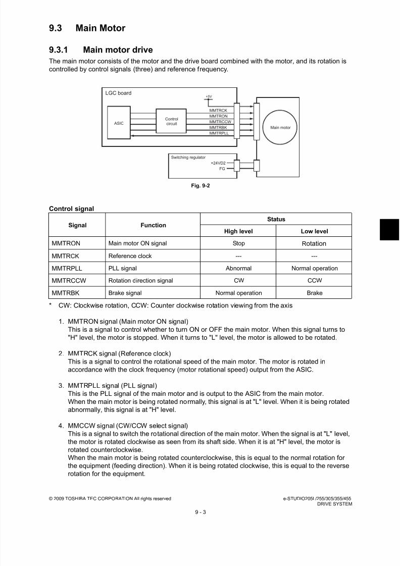
8/17/2019 Toshiba ES455 Service Manual
http://slidepdf.com/reader/full/toshiba-es455-service-manual 213/335
© 2009 TOSHIBA TEC CORPORATION All rights reserved e-STUDIO205L/255/305/355/455DRIVE SYSTEM
9 - 3
9.3 Main Motor
9.3.1 Main motor drive
The main motor consists of the motor and the drive board combined with the motor, and its rotation is
controlled by control signals (three) and reference frequency.
Fig. 9-2
Control signal
* CW: Clockwise rotation, CCW: Counter clockwise rotation viewing from the axis
1. MMTRON signal (Main motor ON signal)
This is a signal to control whether to turn ON or OFF the main motor. When this signal turns to
"H" level, the motor is stopped. When it turns to "L" level, the motor is allowed to be rotated.
2. MMTRCK signal (Reference clock)
This is a signal to control the rotational speed of the main motor. The motor is rotated in
accordance with the clock frequency (motor rotational speed) output from the ASIC.
3. MMTRPLL signal (PLL signal)
This is the PLL signal of the main motor and is output to the ASIC from the main motor.When the main motor is being rotated normally, this signal is at "L" level. When it is being rotated
abnormally, this signal is at "H" level.
4. MMCCW signal (CW/CCW select signal)
This is a signal to switch the rotational direction of the main motor. When the signal is at "L" level,
the motor is rotated clockwise as seen from its shaft side. When it is at "H" level, the motor is
rotated counterclockwise.
When the main motor is being rotated counterclockwise, this is equal to the normal rotation for
the equipment (feeding direction). When it is being rotated clockwise, this is equal to the reverse
rotation for the equipment.
Signal FunctionStatus
High level Low level
MMTRON Main motor ON signal Stop Rotation
MMTRCK Reference clock --- ---
MMTRPLL PLL signal Abnormal Normal operation
MMTRCCW Rotation direction signal CW CCW
MMTRBK Brake signal Normal operation Brake
MMTRON
+5V
Main motor
LGC board
ASICControlcircuit
Switching regulator
MMTRCCW
MMTRCK
MMTRBK
MMTRPLL
FG
+24VD2

8/17/2019 Toshiba ES455 Service Manual
http://slidepdf.com/reader/full/toshiba-es455-service-manual 214/335
e-STUDIO205L/255/305/355/455 © 2009 TOSHIBA TEC CORPORATION All rights reservedDRIVE SYSTEM
9 - 4
5. MMTRBK signal (Brake signal)
This is a signal to put a brake on the main motor. When this signal turns to "L" level, the brake is
applied to the motor. (Normally it is at "H" level.)
The brake is applied to the main motor also when the power supply shut-off signal is output from
the switching regulator or when 24V is shut down (the cover is opened).

8/17/2019 Toshiba ES455 Service Manual
http://slidepdf.com/reader/full/toshiba-es455-service-manual 215/335

8/17/2019 Toshiba ES455 Service Manual
http://slidepdf.com/reader/full/toshiba-es455-service-manual 216/335
e-STUDIO205L/255/305/355/455 © 2009 TOSHIBA TEC CORPORATION All rights reservedDRIVE SYSTEM
9 - 6
9.4.3 Main motor drive unit
(1) Take off the toner motor
P.9-5 "9.4.2 Toner motor (M4)"
(2) Take off the registration roller clutch.
P.8-27 "8.6.24 Registration roller clutch
(CLT2)"
(3) Disconnect 9 connectors. (e-STUDIO205L/
255/305: 4 connectors.)(4) Disconnect 2 connectors of the main motor.
Fig. 9-6
(5) Remove 4 screws and then take off the main
motor drive unit.
Fig. 9-7
e-STUDIO205L/255/305
e-STUDIO355/455
Connector
Main motor drive unit

8/17/2019 Toshiba ES455 Service Manual
http://slidepdf.com/reader/full/toshiba-es455-service-manual 217/335

8/17/2019 Toshiba ES455 Service Manual
http://slidepdf.com/reader/full/toshiba-es455-service-manual 218/335
e-STUDIO205L/255/305/355/455 © 2009 TOSHIBA TEC CORPORATION All rights reservedDRUM RELATED SECTION
10 - 2
10.2 Composition
Drum related section
Drum cleaner unit Drum PM parts
Main charger PM parts
Cleaner
Cleaning blade PM parts
Recovery blade PM parts
Needle electrode PM parts
Discharge LED ERS
Transfer roller unit Transfer roller PM parts
Separation needle
Other Drum thermistor THMS4
High-voltage transformer HVT
Temperature-humidity sensor S25
TRU fan M9
Process unit fan M2
Ozone filter PM parts
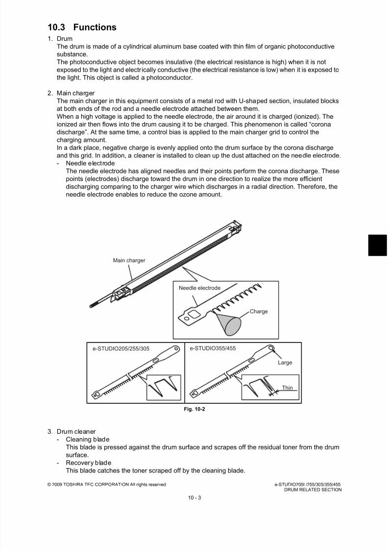
8/17/2019 Toshiba ES455 Service Manual
http://slidepdf.com/reader/full/toshiba-es455-service-manual 219/335
© 2009 TOSHIBA TEC CORPORATION All rights reserved e-STUDIO205L/255/305/355/455DRUM RELATED SECTION
10 - 3
10.3 Functions1. Drum
The drum is made of a cylindrical aluminum base coated with thin film of organic photoconductive
substance.
The photoconductive object becomes insulative (the electrical resistance is high) when it is not
exposed to the light and electrically conductive (the electrical resistance is low) when it is exposed to
the light. This object is called a photoconductor.
2. Main charger The main charger in this equipment consists of a metal rod with U-shaped section, insulated blocks
at both ends of the rod and a needle electrode attached between them.
When a high voltage is applied to the needle electrode, the air around it is charged (ionized). The
ionized air then flows into the drum causing it to be charged. This phenomenon is called “corona
discharge”. At the same time, a control bias is applied to the main charger grid to control the
charging amount.
In a dark place, negative charge is evenly applied onto the drum surface by the corona discharge
and this grid. In addition, a cleaner is installed to clean up the dust attached on the needle electrode.
- Needle electrode
The needle electrode has aligned needles and their points perform the corona discharge. These
points (electrodes) discharge toward the drum in one direction to realize the more efficient
discharging comparing to the charger wire which discharges in a radial direction. Therefore, the
needle electrode enables to reduce the ozone amount.
Fig. 10-2
3. Drum cleaner
- Cleaning blade
This blade is pressed against the drum surface and scrapes off the residual toner from the drum
surface.
- Recovery blade
This blade catches the toner scraped off by the cleaning blade.
Needle electrode
Main charger
Charge
e-STUDIO205/255/305 e-STUDIO355/455
Large
Thin
8/17/2019 Toshiba ES455 Service Manual
http://slidepdf.com/reader/full/toshiba-es455-service-manual 220/335
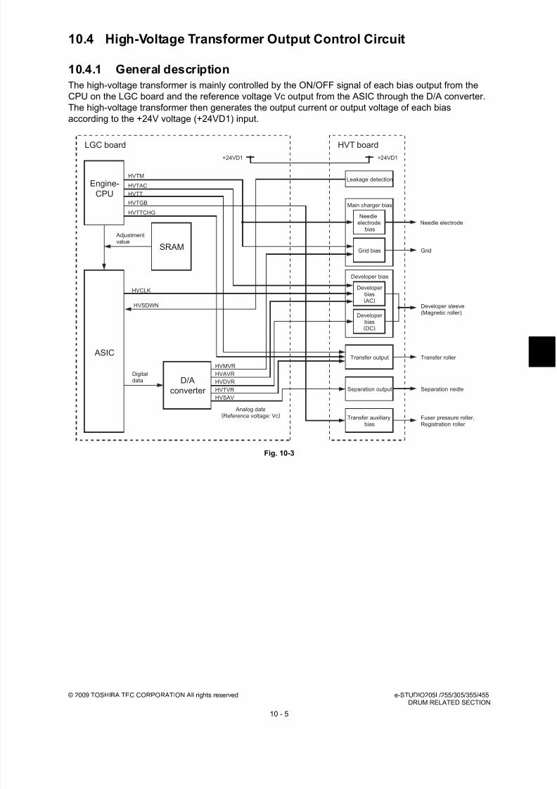
8/17/2019 Toshiba ES455 Service Manual
http://slidepdf.com/reader/full/toshiba-es455-service-manual 221/335
© 2009 TOSHIBA TEC CORPORATION All rights reserved e-STUDIO205L/255/305/355/455DRUM RELATED SECTION
10 - 5
10.4 High-Voltage Transformer Output Control Circuit
10.4.1 General description
The high-voltage transformer is mainly controlled by the ON/OFF signal of each bias output from the
CPU on the LGC board and the reference voltage Vc output from the ASIC through the D/A converter.
The high-voltage transformer then generates the output current or output voltage of each bias
according to the +24V voltage (+24VD1) input.
Fig. 10-3
HVT board
HVMVR
HVAVR
HVDVR
HVTVR
HVSAV
HVTM
HVSDWN
HVTAC
HVCLK
HVTT
HVTGB
SRAM
Engine-
CPU
LGC board
ASIC
D/A
converter
Digitaldata
Adjustmentvalue
+24VD1 +24VD1
Analog data
(Reference voltage: Vc) Transfer auxiliarybias
Transfer output
Separation output
Developer bias
Main charger bias
Leakage detection
Developer bias(DC)
Developer bias( AC)
Grid
Developer sleeve(Magnetic roller)
Transfer roller
Separation nedle
Fuser pressure roller,Registration roller
Grid bias
Needle electrodeNeedle
electrode bias
HVTTCHG

8/17/2019 Toshiba ES455 Service Manual
http://slidepdf.com/reader/full/toshiba-es455-service-manual 222/335

8/17/2019 Toshiba ES455 Service Manual
http://slidepdf.com/reader/full/toshiba-es455-service-manual 223/335
© 2009 TOSHIBA TEC CORPORATION All rights reserved e-STUDIO205L/255/305/355/455DRUM RELATED SECTION
10 - 7
10.5 Drum Temperature Detection Circuit
10.5.1 General description
If the temperature of the drum and its surrounding area becomes too high, the property of the toner
which is recovered by the drum cleaner easily changes. To prevent this, the drum thermistor detects the
surface temperature of the drum. Based on the result, it controls the process unit fan to cool down the
inside of the equipment.
10.5.2 Construction
The configuration of the drum temperature detection circuit is shown below. The voltage detected by
the drum thermistor is input to the CPU on the LGC board through the EPU memory board.
The higher the detected temperature is, the smaller the resistance of the drum thermistor becomes.
Therefore the input voltage to the CPU is lowered as the temperature rises.
Fig. 10-4
SG
SG
+3.3V
LGC board
Drum
thermistor
DRTH-1A CPU
EPU memoryboard

8/17/2019 Toshiba ES455 Service Manual
http://slidepdf.com/reader/full/toshiba-es455-service-manual 224/335
e-STUDIO205L/255/305/355/455 © 2009 TOSHIBA TEC CORPORATION All rights reservedDRUM RELATED SECTION
10 - 8
10.6 Temperature/Humidity Detection Circuit
10.6.1 General description
To prevent a deterioration of printing quality by the variation of the temperature and humidity where the
equipment is installed, the temperature/humidity sensor detects the temperature and humidity of the
outside air taken into the equipment. Based on the result of the detection, this circuit corrects each
output of main charger bias, developer bias, transfer bias and separation bias, output of the auto-toner
sensor and output of the laser.
10.6.2 Construction
The configuration of the temperature/humidity detection circuit is shown below. The voltage detected by
the temperature/humidity sensor is input to the CPU of the LGC board.
Signals output from the temperature/humidity sensor indicate that the higher the temperature is, the
lower the detected voltage becomes, and the higher the humidity is, the higher the detected voltage
becomes.
Fig. 10-5
+5V
SG
SG
+3.3V
-
+
LGC board
HUMI-THS
TEMP-1
HMS-1
CPU
RTH
(TEMP)
VRHV
(HUM)

8/17/2019 Toshiba ES455 Service Manual
http://slidepdf.com/reader/full/toshiba-es455-service-manual 225/335
© 2009 TOSHIBA TEC CORPORATION All rights reserved e-STUDIO205L/255/305/355/455DRUM RELATED SECTION
10 - 9
10.7 Disassembly and Replacement
10.7.1 Process unit
10.7.2 Drum cleaner unit
(1) Open the automatic duplexing unit.
(2) Open the front cover and take off the toner
cartridge.
(3) Loosen 2 screws and pull out the process
unit.
Fig. 10-6
(1) Take off the process unit
( P.10-9 "10.7.1 Process unit").
(2) Release 1 latch. Then pull out the harness
cover and take it off.
Fig. 10-7
(3) Remove 1 screw and the ground wire, and
then disconnect 3 connectors.
Fig. 10-8
Process unit
Harness cover
Connector
Connector
Connector
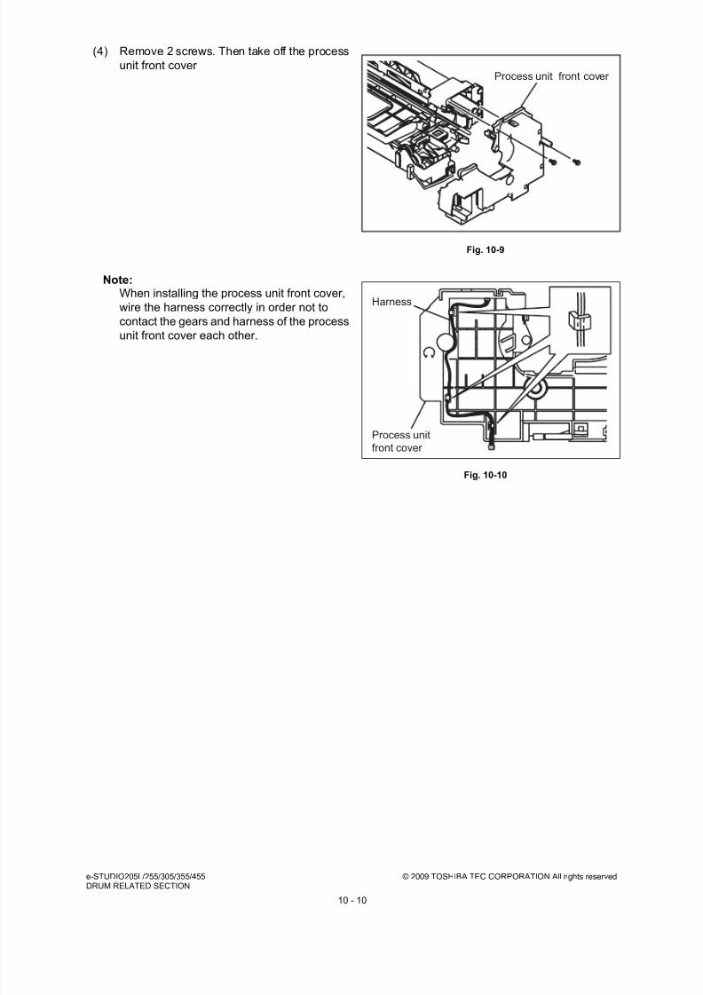
8/17/2019 Toshiba ES455 Service Manual
http://slidepdf.com/reader/full/toshiba-es455-service-manual 226/335
e-STUDIO205L/255/305/355/455 © 2009 TOSHIBA TEC CORPORATION All rights reservedDRUM RELATED SECTION
10 - 10
(4) Remove 2 screws. Then take off the process
unit front cover
Note:When installing the process unit front cover,
wire the harness correctly in order not to
contact the gears and harness of the process
unit front cover each other.
Fig. 10-9
Fig. 10-10
Process unit front cover
Process unit
front cover
Harness
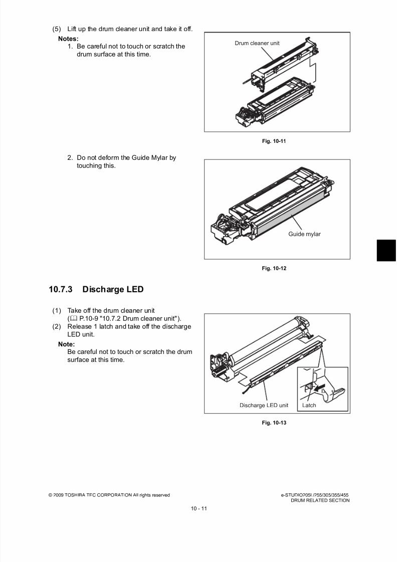
8/17/2019 Toshiba ES455 Service Manual
http://slidepdf.com/reader/full/toshiba-es455-service-manual 227/335
© 2009 TOSHIBA TEC CORPORATION All rights reserved e-STUDIO205L/255/305/355/455DRUM RELATED SECTION
10 - 11
10.7.3 Discharge LED
(5) Lift up the drum cleaner unit and take it off.
Notes:1. Be careful not to touch or scratch the
drum surface at this time.
2. Do not deform the Guide Mylar by
touching this.
Fig. 10-11
Fig. 10-12
(1) Take off the drum cleaner unit
( P.10-9 "10.7.2 Drum cleaner unit").
(2) Release 1 latch and take off the discharge
LED unit.
Note:Be careful not to touch or scratch the drum
surface at this time.
Fig. 10-13
Drum cleaner unit
Guide mylar
Discharge LED unit Latch

8/17/2019 Toshiba ES455 Service Manual
http://slidepdf.com/reader/full/toshiba-es455-service-manual 228/335
e-STUDIO205L/255/305/355/455 © 2009 TOSHIBA TEC CORPORATION All rights reservedDRUM RELATED SECTION
10 - 12
10.7.4 Main charger
(3) Release the harness from the harness clamp
and pull out the discharge LED.
Note:The number of the discharge LEDs for the e-
STUDIO205L/255/305 differs from that for
the e-STUDIO355/455, therefore do not
install the LEDs in a wrong model.
Fig. 10-14
(1) Take off the discharge LED unit
( P.10-11 "10.7.3 Discharge LED").
(2) Pull out the main charger and take it off by
sliding it to the rear side.
Note:Be careful not to touch or scratch the drum
surface at this time.
Fig. 10-15
Discharge LED
e-STUDIO205L/255/305
e-STUDIO355/455
Main charger

8/17/2019 Toshiba ES455 Service Manual
http://slidepdf.com/reader/full/toshiba-es455-service-manual 229/335
© 2009 TOSHIBA TEC CORPORATION All rights reserved e-STUDIO205L/255/305/355/455DRUM RELATED SECTION
10 - 13
10.7.5 Main charger grid
10.7.6 Main charger cleaner
10.7.7 Needle electrode
(1) Take off the main charger
( P.10-12 "10.7.4 Main charger").
(2) Remove the spring and take off the main
charger grid.
Note:Do not touch the mesh area of the grid.
Fig. 10-16
(1) Take off the main charger( P.10-12 "10.7.4 Main charger").
(2) Release the hook of the cleaning shaft. Then
rotate the shaft at 90 degrees to take it off.
Fig. 10-17
(1) Take off the main charger grid and main
charger cleaner.
P.10-13 "10.7.5 Main charger grid"
P.10-13 "10.7.6 Main charger cleaner"
(2) Take off the terminal covers of both front and
rear sides.
Fig. 10-18
Main charger grid
Spring
Main charger cleaner
Terminal cover

8/17/2019 Toshiba ES455 Service Manual
http://slidepdf.com/reader/full/toshiba-es455-service-manual 230/335
e-STUDIO205L/255/305/355/455 © 2009 TOSHIBA TEC CORPORATION All rights reservedDRUM RELATED SECTION
10 - 14
10.7.8 Drum
(3) Remove the terminal and spring. Then take
off the needle electrode.
Notes:1. Do not touch the needle electrode directly
with bare hands.
2. Make sure not to hold or bend the needle
electrode.
3. The form of the needle electrode differs
depending on the model as shown in the
figure.
Do not mix them when installing.
Fig. 10-19
Fig. 10-20
(1) Take off the main charger
( P.10-12 "10.7.4 Main charger").
(2) Rotate the lever while pushing its latch and
pull it out.
(3) Take off the drum.
Notes:1. Be careful not to touch, spit or scratch the
drum surface.
2. Avoid direct light. Place the drum in a
dark place immediately after taking off.
3. Be careful not to touch or scratch the
edge of the cleaning blade.
Fig. 10-21
Needle electrode
Terminal
Spring
3.55 mm
2.5 mm
e-STUDIO355/455
e-STUDIO205L/255/305
Drum
Lever

8/17/2019 Toshiba ES455 Service Manual
http://slidepdf.com/reader/full/toshiba-es455-service-manual 231/335
© 2009 TOSHIBA TEC CORPORATION All rights reserved e-STUDIO205L/255/305/355/455DRUM RELATED SECTION
10 - 15
10.7.9 Drum cleaning blade
10.7.10 Drum separation finger
(1) Take off the drum
( P.10-14 "10.7.8 Drum").
(2) Remove 2 screws and take off the drum
cleaning blade.
Note:Be careful not to touch or scratch the edge of
the drum cleaning blade.
Fig. 10-22
(1) Take off the drum
( P.10-14 "10.7.8 Drum").
(2) Remove 1 screw of each unit to take off the
drum separation finger units (2 pc.).
Note:1. When replacing the drum separation
fingers, make sure that the drum has been
taken off first since the fingers may scratch
the drum surface.
Fig. 10-23
(3) Remove the spring and take off the drum
separation fingers.
Note:When the drum separation fingers have been
replaced, check if the pressure movement is
normal by moving them with your hands.
Fig. 10-24
Drum cleaning blade
Drum separation finger unit
Drum separation finger Spring
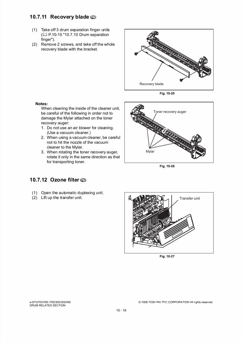
8/17/2019 Toshiba ES455 Service Manual
http://slidepdf.com/reader/full/toshiba-es455-service-manual 232/335

8/17/2019 Toshiba ES455 Service Manual
http://slidepdf.com/reader/full/toshiba-es455-service-manual 233/335
© 2009 TOSHIBA TEC CORPORATION All rights reserved e-STUDIO205L/255/305/355/455DRUM RELATED SECTION
10 - 17
10.7.13 TRU fan (M9)
(3) Release 1 hook and then take off the filter
cover.
Fig. 10-28
(4) Take off the ozone filter.
Fig. 10-29
(1) Take off the transfer unit
( P.10-20 "10.7.17 Transfer unit").
(2) Remove 1 screw and then take off the
terminal on the rear side.
Fig. 10-30
Filter cover
Ozone filter
Terminal

8/17/2019 Toshiba ES455 Service Manual
http://slidepdf.com/reader/full/toshiba-es455-service-manual 234/335
e-STUDIO205L/255/305/355/455 © 2009 TOSHIBA TEC CORPORATION All rights reservedDRUM RELATED SECTION
10 - 18
10.7.14 Transfer roller unit
(3) Remove 4 screws and then take off the inner
duct.
Fig. 10-31
(4) Take off the TRU fan.
Fig. 10-32
(1) Open the automatic duplexing unit.
(2) Release the hook on the rear side and then
take off the transfer roller unit.
Notes:1. Be careful not to drop the spring.
2. When installing the charger, pay attention
to the position of the spring.
Fig. 10-33
Inner duct
TRU fan
Transfer roller unit

8/17/2019 Toshiba ES455 Service Manual
http://slidepdf.com/reader/full/toshiba-es455-service-manual 235/335
© 2009 TOSHIBA TEC CORPORATION All rights reserved e-STUDIO205L/255/305/355/455DRUM RELATED SECTION
10 - 19
10.7.15 Transfer roller
10.7.16 Separation needle
(1) Take off the transfer roller unit
( P.10-18 "10.7.14 Transfer roller unit").
(2) Release 4 hooks and then take off the
transfer roller.
Note:Be careful not to drop the spring.
Fig. 10-34
(3) Remove 1 gear, 2 guide rollers and 2
bushings from the transfer roller.
Note:
When installing the bushings and gear, payattention to the direction of them.
Fig. 10-35
(1) Take off the transfer roller unit.
( P.10-18 "10.7.14 Transfer roller unit").
(2) Release 2 hooks and then take off the cover.
(3) Take off the separation needle paying
attention not to deform it.
Note:When installing the separation needle, be
sure to insert it underneath the power supply
plate.
Fig. 10-36
Transfer roller
Gear
Transfer roller
Bushing
Guide roller
Bushing
Guide roller
Separation needle
Cover
Power supply plate

8/17/2019 Toshiba ES455 Service Manual
http://slidepdf.com/reader/full/toshiba-es455-service-manual 236/335
e-STUDIO205L/255/305/355/455 © 2009 TOSHIBA TEC CORPORATION All rights reservedDRUM RELATED SECTION
10 - 20
10.7.17 Transfer unit
Note:When taking off the transfer unit, take off the process unit first to prevent the drum from light.
10.7.18 Temperature/humidity sensor (S25)
(1) Take off the automatic duplexing unit.
P.14-9 "14.5.1 Automatic Duplexing Unit
(ADU)"
(2) Take off 2 brackets by removing 2 screwseach.
(3) Disconnect 1 connector and then take off the
transfer unit.
Fig. 10-37
(1) Take off the rear cover.
P.2-22 "2.5.6 Rear cover"
(2) Disconnect 1 connector, remove 1 screw and
then take off the temperature/humidity
sensor.
Fig. 10-38
Transfer unit
Temperature/humidity sensor

8/17/2019 Toshiba ES455 Service Manual
http://slidepdf.com/reader/full/toshiba-es455-service-manual 237/335
© 2009 TOSHIBA TEC CORPORATION All rights reserved e-STUDIO205L/255/305/355/455DEVELOPMENT SYSTEM
11 - 1
11. DEVELOPMENT SYSTEM
11.1 ConfigurationThe developer unit in this equipment has a recovered toner supply mechanism which recovers the
recovered toner scraped off by the drum cleaning blade and recycles the recovered toner. The
developer unit is driven by the main motor to rotate the mixers and developer sleeve.
Fig. 11-1
Doctor blade
Drum
Developer sleeve Auto-toner sensor
Mixer-3
Mixer-1Mixer-2
Drum thermistor
Toner recycling auger
Toner
recovery roller (e-STUDIO355/455)

8/17/2019 Toshiba ES455 Service Manual
http://slidepdf.com/reader/full/toshiba-es455-service-manual 238/335
e-STUDIO205L/255/305/355/455 © 2009 TOSHIBA TEC CORPORATION All rights reservedDEVELOPMENT SYSTEM
11 - 2
11.2 Construction
Developer unit Developer material PM parts
Mixers-1, -2 and -3
Developer sleeve (Magnet roller)
Doctor blade
Auto-toner sensor S8
Drum thermistor THMS4
EPU memory board EPU
Recovered toner supply mechanism(Toner recycling auger)
Toner cartridge Toner cartridge PC board CTRG
Toner cartridge interface PC board CTIF
Toner motor M4
8/17/2019 Toshiba ES455 Service Manual
http://slidepdf.com/reader/full/toshiba-es455-service-manual 239/335
© 2009 TOSHIBA TEC CORPORATION All rights reserved e-STUDIO205L/255/305/355/455DEVELOPMENT SYSTEM
11 - 3
11.3 Functions
11.3.1 General description
1. Toner cartridge drive unit / Toner cartridge installation detection mechanism (IC chip)
The toner cartridge is filled with toner. The toner motor drives the cartridge to supply the toner to the
developer unit.
The IC chip detects whether a toner cartridge is installed.
2. Developer unit- Developer material
The developer material is made of a mixture of the carrier and toner.
The carrier is an electrical conductive ferrite whose size is approx 44 µm. The toner is a resin
particle whose size is approx 8.5 µm.
The developer material needs periodic replacement since its quality is deteriorated by long use.
- Mixers-1, -2 and -3
Friction is generated by mixing the developer material. The carrier is charged to (+) and the toner
to (–), and the image is formed on the drum surface by the static electricity caused by the friction.
The mixer-3 is mounted exclusively for the recovered toner to mix it with sufficient time.
- Developer sleeve (Magnetic roller)This is an aluminum roller with a magnet inside. The magnet works to absorb the developer
material and forms the magnetic brush. The magnet is fixed and only the sleeve around is
rotated. This rotation makes the magnetic brush of the developer sleeve sweep over the drum
surface and perform development.
- Doctor blade
Doctor blade controls the amount of the developer material transported by the developer sleeve
so that the magnetic brush of the developer material contacts with the drum surface properly.
- Auto-toner sensor
The carrier and the toner (toner density) in the developer material should be always fixed to a
certain ratio to output normal images. The auto-toner sensor detects the inclusion ratio of the
toner in the developer material by using a magnetic bridge circuit. When the quantity of toner
becomes insufficient, the toner motor is driven to supply the toner from the toner cartridge.
- Recovered toner supply mechanism
The recovered toner transported from the drum cleaner is transported into the developer unit by
the toner recycling auger on the front side of the developer unit. The drive of the toner recycling
auger is transmitted by the mixer-3.

8/17/2019 Toshiba ES455 Service Manual
http://slidepdf.com/reader/full/toshiba-es455-service-manual 240/335
e-STUDIO205L/255/305/355/455 © 2009 TOSHIBA TEC CORPORATION All rights reservedDEVELOPMENT SYSTEM
11 - 4
11.3.2 Recovered process unit mechanism
The process unit of this equipment has two types; one is for the e-STUDIO205L/255/305 and another is
for the e-STUDIO355/455.
The differences between two are shown below.
Be sure not to install the process unit to a wrong model when replacing them because they are
incompatible each other.
To distinguish them, check the position of the bracket hole seen from the back side.
Fig. 11-2
Parts e-STUDIO205L/255/305 e-STUDIO355/455Toner recovery roller Not installed Installed
Gear, belt For low speed For high speed
Discharge LED 10 LEDs 14 LEDs
Needle electrode For low speed For high speed
Position of bracket hole(seen from the back side)
Bottom Top
Discharge LED
Needle electrode
Pulley Belt
Tonerrecovery roller
e-STUDIO205L/255/305 e-STUDIO355/455

8/17/2019 Toshiba ES455 Service Manual
http://slidepdf.com/reader/full/toshiba-es455-service-manual 241/335
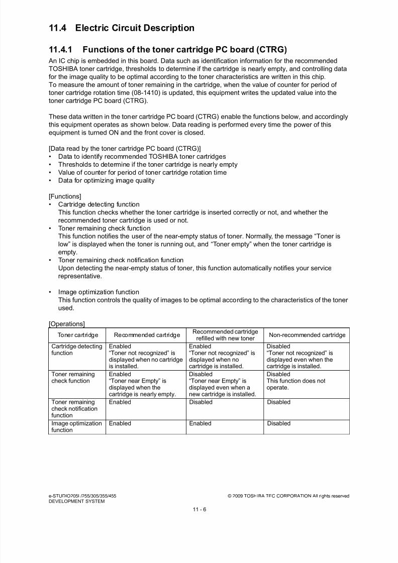
8/17/2019 Toshiba ES455 Service Manual
http://slidepdf.com/reader/full/toshiba-es455-service-manual 242/335
e-STUDIO205L/255/305/355/455 © 2009 TOSHIBA TEC CORPORATION All rights reservedDEVELOPMENT SYSTEM
11 - 6
11.4 Electric Circuit Description
11.4.1 Functions of the toner cartridge PC board (CTRG)
An IC chip is embedded in this board. Data such as identification information for the recommended
TOSHIBA toner cartridge, thresholds to determine if the cartridge is nearly empty, and controlling data
for the image quality to be optimal according to the toner characteristics are written in this chip.
To measure the amount of toner remaining in the cartridge, when the value of counter for period of
toner cartridge rotation time (08-1410) is updated, this equipment writes the updated value into the
toner cartridge PC board (CTRG).
These data written in the toner cartridge PC board (CTRG) enable the functions below, and accordingly
this equipment operates as shown below. Data reading is performed every time the power of this
equipment is turned ON and the front cover is closed.
[Data read by the toner cartridge PC board (CTRG)]
• Data to identify recommended TOSHIBA toner cartridges
• Thresholds to determine if the toner cartridge is nearly empty
• Value of counter for period of toner cartridge rotation time
• Data for optimizing image quality
[Functions]• Cartridge detecting function
This function checks whether the toner cartridge is inserted correctly or not, and whether the
recommended toner cartridge is used or not.
• Toner remaining check function
This function notifies the user of the near-empty status of toner. Normally, the message “Toner is
low” is displayed when the toner is running out, and “Toner empty” when the toner cartridge is
empty.
• Toner remaining check notification function
Upon detecting the near-empty status of toner, this function automatically notifies your service
representative.
• Image optimization function
This function controls the quality of images to be optimal according to the characteristics of the toner
used.
[Operations]
Toner cartridge Recommended cartridgeRecommended cartridge
refilled with new toner Non-recommended cartridge
Cartridge detectingfunction
Enabled“Toner not recognized” isdisplayed when no cartridgeis installed.
Enabled“Toner not recognized” isdisplayed when nocartridge is installed.
Disabled“Toner not recognized” isdisplayed even when thecartridge is installed.
Toner remainingcheck function
Enabled“Toner near Empty” isdisplayed when the
cartridge is nearly empty.
Disabled“Toner near Empty” isdisplayed even when a
new cartridge is installed.
DisabledThis function does notoperate.
Toner remainingcheck notificationfunction
Enabled Disabled Disabled
Image optimizationfunction
Enabled Enabled Disabled
8/17/2019 Toshiba ES455 Service Manual
http://slidepdf.com/reader/full/toshiba-es455-service-manual 243/335
© 2009 TOSHIBA TEC CORPORATION All rights reserved e-STUDIO205L/255/305/355/455DEVELOPMENT SYSTEM
11 - 7
A sign of the status that the toner cartridge is nearly empty (= the behavior of the toner lamp) appears
when the value of counter for period of toner cartridge rotation time has exceeded the thresholds
previously written in the toner cartridge PC board (CTRG). When a used cartridge refilled with new
toner is used, that is the value of counter for period of toner cartridge rotation time in the toner cartridge
PC board (CTRG) had already exceeded the threshold to determine the near-empty status of the toner
at this moment, the sign of the near-empty status appears immediately after the installation of this
cartridge. When a non-recommended toner cartridge is used, "Toner not recognized" appears on the
touch panel, the equipment may stop normal operations. The toner remaining check function, automatic
remote supply order to TOSHIBA sales representatives and image optimization function may also be
disabled.The toner near-empty status threshold setting (08-971) is provided to adjust the timing for displaying
the toner near-empty status as follows.
The toner near-empty status threshold setting (08-971)
0: The period from the appearance of the toner near-empty sign to the actual complete
consumption of the toner is set long.
1: Normal (Default)
2: The period from the appearance of the toner near-empty sign to the actual complete
consumption of the toner is set short.
3: The sign of the status that the cartridge is nearly empty does not appear.
Note that the shorter the period described above is set, the more frequently the toner in the cartridgemay run out before the sign of the near-empty status of the toner appears because the way the toner
remains in the cartridge differs every time.
When the value of the toner near-empty status threshold setting (08-971) is set at “3”, the toner
remaining check function is disabled.
When the cartridge detecting function is set to OFF (08-499 is set at “0”), the value of the toner near-
empty status threshold setting (08-971) is automatically set at “3” and the toner remaining check
function is disabled
When the cartridge detecting function is set to ON (08-499 is set at “1” or “2”), the value of the toner
near-empty status threshold setting (08-971) is automatically set at “1” and the toner remaining check
function is enabled.
Cartridge detecting function (08-499)
0: Not detected
1: Only displays a warning message (user selection)
2: Printing stops
When "0" is set for this code, the functions of the toner cartridge PC board (CTRG) will be disabled.
When "1" is set, the equipment will confirm whether the user can continue using the current toner
cartridges, if the recommended TOSHIBA toner cartridge data cannot be verified.
When "2" is set, all print jobs requiring toner cartridges will be disabled if the recommended TOSHIBA
toner cartridge data cannot be verified.
Image optimization function
Data for controlling the image quality according to the toner characteristics are written in the toner
cartridge PC board (CTRG) so that images can be optimally printed.
Also there is a function that sets the image controlling level as required (08-5101).
0: Controlling amount - Medium (default)
1: Controlling amount - Small
2: Controlling amount - Large
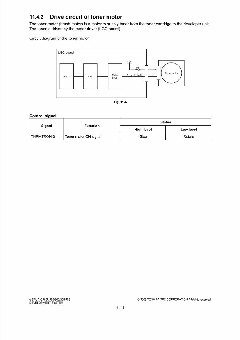
8/17/2019 Toshiba ES455 Service Manual
http://slidepdf.com/reader/full/toshiba-es455-service-manual 244/335
e-STUDIO205L/255/305/355/455 © 2009 TOSHIBA TEC CORPORATION All rights reservedDEVELOPMENT SYSTEM
11 - 8
11.4.2 Drive circuit of toner motor The toner motor (brush motor) is a motor to supply toner from the toner cartridge to the developer unit.
The toner is driven by the motor driver (LGC board).
Circuit diagram of the toner motor
Fig. 11-4
Control signal
Signal FunctionStatus
High level Low level
TNRMTRON-0 Toner motor ON signal Stop Rotate
CPUTNRMTRON-0
+24V
Toner motor
LGC board
F1
ASICMotor driver

8/17/2019 Toshiba ES455 Service Manual
http://slidepdf.com/reader/full/toshiba-es455-service-manual 245/335
© 2009 TOSHIBA TEC CORPORATION All rights reserved e-STUDIO205L/255/305/355/455DEVELOPMENT SYSTEM
11 - 9
11.5 Auto-Toner Circuit
11.5.1 General description
1. Function of the auto-toner circuit
- Detects the toner density in the developer material, and supplies toner when the density is
lowered to a certain level.
- Detects that there is no toner left in the cartridge (toner-empty detection).
2. The auto-toner circuit consists of the following:
- Auto-toner sensor:
Detects the toner density.
- Control section:
Controls the toner density so that the toner in the developer material is fixed to certain ratio.
- Toner motor:
Supplies toner to the developer material.
Fig. 11-5
SRAM ASIC
CPU
Motor driver
Temperature/humidity sensor
LGC board
Developer unit
Toner density signal
Control voltage signal
Auto-toner sensor
Toner
Toner cartridge
Toner motor
Developer material
D/Aconverter
A/D converter
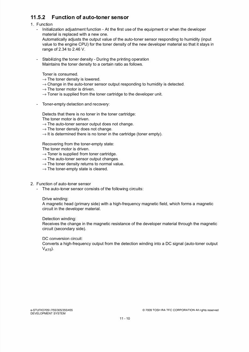
8/17/2019 Toshiba ES455 Service Manual
http://slidepdf.com/reader/full/toshiba-es455-service-manual 246/335
e-STUDIO205L/255/305/355/455 © 2009 TOSHIBA TEC CORPORATION All rights reservedDEVELOPMENT SYSTEM
11 - 10
11.5.2 Function of auto-toner sensor
1. Function
- Initialization adjustment function - At the first use of the equipment or when the developer
material is replaced with a new one.
Automatically adjusts the output value of the auto-toner sensor responding to humidity (input
value to the engine CPU) for the toner density of the new developer material so that it stays in
range of 2.34 to 2.46 V.
- Stabilizing the toner density - During the printing operation
Maintains the toner density to a certain ratio as follows.
Toner is consumed.
→ The toner density is lowered.
→ Change in the auto-toner sensor output responding to humidity is detected.
→ The toner motor is driven.
→ Toner is supplied from the toner cartridge to the developer unit.
- Toner-empty detection and recovery:
Detects that there is no toner in the toner cartridge:
The toner motor is driven.
→ The auto-toner sensor output does not change.→ The toner density does not change.
→ It is determined there is no toner in the cartridge (toner empty).
Recovering from the toner-empty state:
The toner motor is driven.
→ Toner is supplied from toner cartridge.
→ The auto-toner sensor output changes.
→ The toner density returns to normal value.
→ The toner-empty state is cleared.
2. Function of auto-toner sensor - The auto-toner sensor consists of the following circuits:
Drive winding:
A magnetic head (primary side) with a high-frequency magnetic field, which forms a magnetic
circuit in the developer material.
Detection winding:
Receives the change in the magnetic resistance of the developer material through the magnetic
circuit (secondary side).
DC conversion circuit:
Converts a high-frequency output from the detection winding into a DC signal (auto-toner output
V ATS).
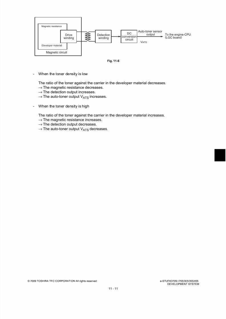
8/17/2019 Toshiba ES455 Service Manual
http://slidepdf.com/reader/full/toshiba-es455-service-manual 247/335
© 2009 TOSHIBA TEC CORPORATION All rights reserved e-STUDIO205L/255/305/355/455DEVELOPMENT SYSTEM
11 - 11
Fig. 11-6
- When the toner density is low
The ratio of the toner against the carrier in the developer material decreases.
→ The magnetic resistance decreases.
→ The detection output increases.
→ The auto-toner output V ATS increases.
- When the toner density is high
The ratio of the toner against the carrier in the developer material increases.
→ The magnetic resistance increases.
→ The detection output decreases.
→ The auto-toner output V ATS decreases.
Drivewinding
Detectionwinding
DCconversion
circuit
Auto-toner sensoroutput To the engine-CPU
(LGC board)
V ATS
Magnetic circuit
Magnetic resistance
(Developer material)

8/17/2019 Toshiba ES455 Service Manual
http://slidepdf.com/reader/full/toshiba-es455-service-manual 248/335
e-STUDIO205L/255/305/355/455 © 2009 TOSHIBA TEC CORPORATION All rights reservedDEVELOPMENT SYSTEM
11 - 12
11.6 Disassembly and Replacement
11.6.1 Process unit
(1) Open the automatic duplexing unit.
(2) Open the front cover and take off the toner
cartridge.
(3) Loosen 2 screws and pull out the process
unit.
Fig. 11-7
Process unit

8/17/2019 Toshiba ES455 Service Manual
http://slidepdf.com/reader/full/toshiba-es455-service-manual 249/335
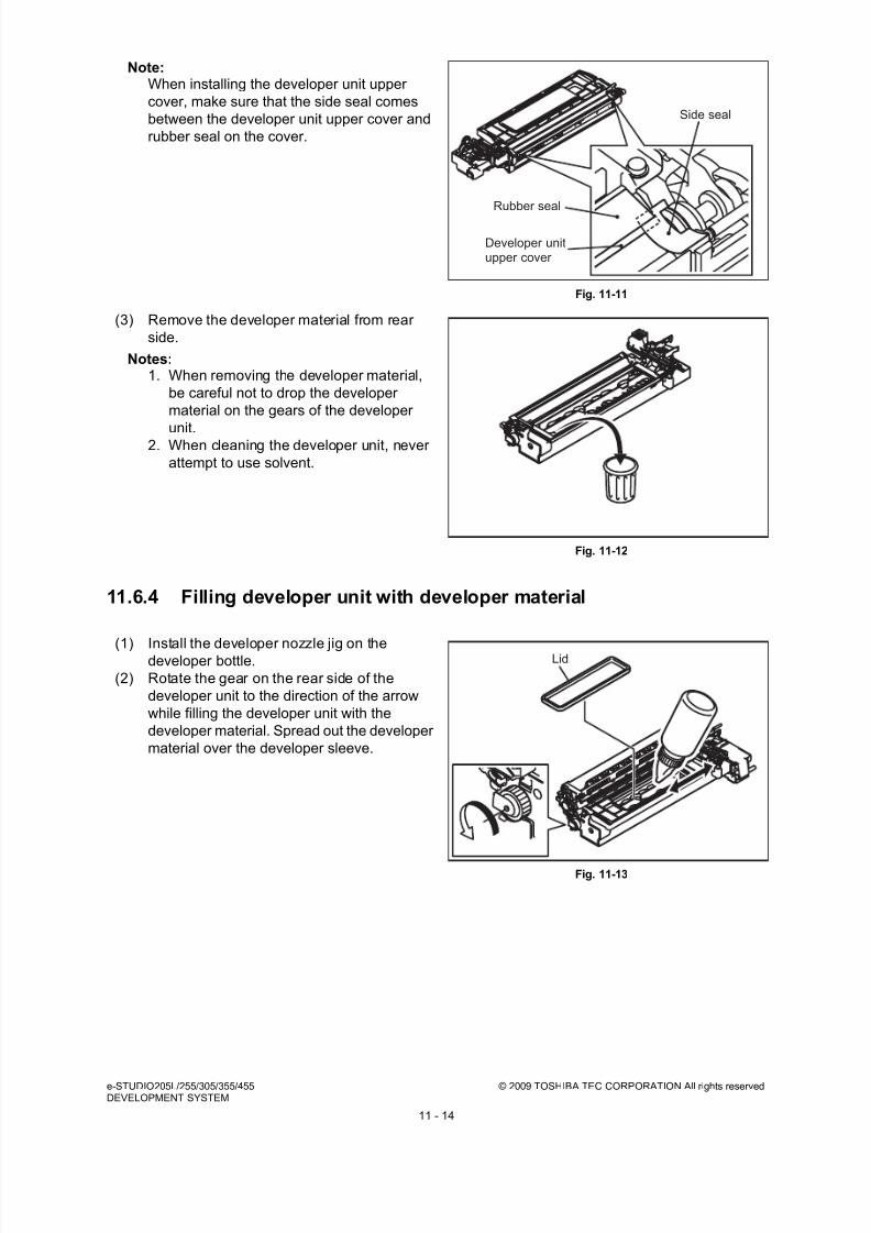
8/17/2019 Toshiba ES455 Service Manual
http://slidepdf.com/reader/full/toshiba-es455-service-manual 250/335
e-STUDIO205L/255/305/355/455 © 2009 TOSHIBA TEC CORPORATION All rights reservedDEVELOPMENT SYSTEM
11 - 14
11.6.4 Filling developer unit with developer material
Note:When installing the developer unit upper
cover, make sure that the side seal comes
between the developer unit upper cover and
rubber seal on the cover.
Fig. 11-11
(3) Remove the developer material from rear
side.
Notes:1. When removing the developer material,
be careful not to drop the developer
material on the gears of the developer
unit.2. When cleaning the developer unit, never
attempt to use solvent.
Fig. 11-12
(1) Install the developer nozzle jig on thedeveloper bottle.
(2) Rotate the gear on the rear side of the
developer unit to the direction of the arrow
while filling the developer unit with the
developer material. Spread out the developer
material over the developer sleeve.
Fig. 11-13
Side seal
Rubber seal
Developer unitupper cover
Lid

8/17/2019 Toshiba ES455 Service Manual
http://slidepdf.com/reader/full/toshiba-es455-service-manual 251/335
© 2009 TOSHIBA TEC CORPORATION All rights reserved e-STUDIO205L/255/305/355/455DEVELOPMENT SYSTEM
11 - 15
11.6.5 EPU memory board (EPU)
11.6.6 Auto-toner sensor (S8)
(1) Remove the developer material
( P.11-13 "11.6.3 Removing developer
material").
(2) Place the developer unit upside down.
Disconnect 2 connectors.
Fig. 11-14
(3) Remove 1 screw. Then take off the EPU
memory board.
Fig. 11-15
(1) Remove the developer material
( P.11-13 "11.6.3 Removing developer
material").
(2) Place the developer unit upside down.
Disconnect 1 connector.
Fig. 11-16
EPU memory board
EPU memory board
Connector

8/17/2019 Toshiba ES455 Service Manual
http://slidepdf.com/reader/full/toshiba-es455-service-manual 252/335
e-STUDIO205L/255/305/355/455 © 2009 TOSHIBA TEC CORPORATION All rights reservedDEVELOPMENT SYSTEM
11 - 16
11.6.7 Drum thermistor (THMS4)
11.6.8 Guide roller / Developer sleeve
(3) Take off the auto-toner sensor by rotating it.
Fig. 11-17
(1) Remove the developer material
( P.11-13 "11.6.3 Removing developer
material").
(2) Disconnect 1 connector, remove 1 screw andtake off the drum thermistor.
Fig. 11-18
(1) Remove the developer material
( P.11-13 "11.6.3 Removing developer
material").
(2) Remove 2 screws and take off the recovered
toner supply unit.
Fig. 11-19
Auto-toner sensor
Connector
Drum thermistor
Recovered toner supply unit
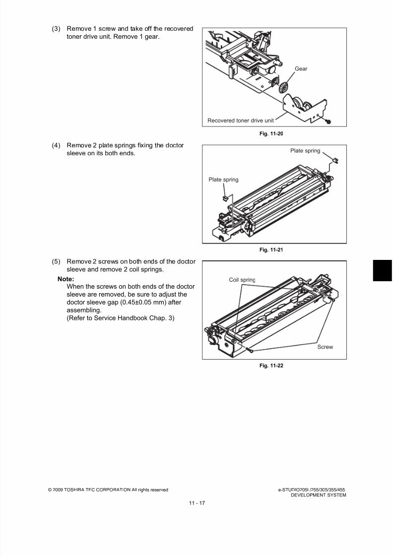
8/17/2019 Toshiba ES455 Service Manual
http://slidepdf.com/reader/full/toshiba-es455-service-manual 253/335
© 2009 TOSHIBA TEC CORPORATION All rights reserved e-STUDIO205L/255/305/355/455DEVELOPMENT SYSTEM
11 - 17
(3) Remove 1 screw and take off the recovered
toner drive unit. Remove 1 gear.
Fig. 11-20
(4) Remove 2 plate springs fixing the doctor
sleeve on its both ends.
Fig. 11-21
(5) Remove 2 screws on both ends of the doctor
sleeve and remove 2 coil springs.
Note:When the screws on both ends of the doctor
sleeve are removed, be sure to adjust thedoctor sleeve gap (0.45±0.05 mm) after
assembling.
(Refer to Service Handbook Chap. 3)
Fig. 11-22
Gear
Recovered toner drive unit
Plate spring
Plate spring
Screw
Coil spring

8/17/2019 Toshiba ES455 Service Manual
http://slidepdf.com/reader/full/toshiba-es455-service-manual 254/335
e-STUDIO205L/255/305/355/455 © 2009 TOSHIBA TEC CORPORATION All rights reservedDEVELOPMENT SYSTEM
11 - 18
(6) Remove 1 screw and plate spring.
(only e-STUDIO355/455)
(7) Remove 1 screw and take off the polarity
adjustment lever.
Note:Make a note of the position where the
polarity adjustment lever is pointing. (Mark
the position if needed.) When reassembling,
match the polarity adjustment lever with the
previously marked position on the scale.
Fig. 11-23
(8) Remove 2 screws and take off the bracket.
Fig. 11-24
(9) Remove 1 E-ring and take off the guide roller
on the front side.
Fig. 11-25
Plate spring
Polarity adjustment lever
Bracket
E-ring Guide roller

8/17/2019 Toshiba ES455 Service Manual
http://slidepdf.com/reader/full/toshiba-es455-service-manual 255/335

8/17/2019 Toshiba ES455 Service Manual
http://slidepdf.com/reader/full/toshiba-es455-service-manual 256/335

8/17/2019 Toshiba ES455 Service Manual
http://slidepdf.com/reader/full/toshiba-es455-service-manual 257/335
© 2009 TOSHIBA TEC CORPORATION All rights reserved e-STUDIO205L/255/305/355/455DEVELOPMENT SYSTEM
11 - 21
11.6.9 Mixer
(17) Take off the developer sleeve.
Fig. 11-32
(1) Take off the developer sleeve
( P.11-16 "11.6.8 Guide roller / Developer
sleeve").
(2) Take off the doctor sleeve.
Fig. 11-33
(3) Remove 2 screws and take off the holder.
Fig. 11-34
Developer sleeve
Doctor sleeve
Holder

8/17/2019 Toshiba ES455 Service Manual
http://slidepdf.com/reader/full/toshiba-es455-service-manual 258/335
e-STUDIO205L/255/305/355/455 © 2009 TOSHIBA TEC CORPORATION All rights reservedDEVELOPMENT SYSTEM
11 - 22
(4) Remove 2 bushings and 2 oil seals from the
holder.
(Replacement of Oil Seal: P.11-24
"11.6.10 Replacement of oil seal")
Fig. 11-35
(5) Take off the mixers-2 and -3.
Fig. 11-36
(6) Remove 2 bushings and 2 oil seals on the
front side.
(Replacement of Oil Seal: P.11-24
"11.6.10 Replacement of oil seal"
Fig. 11-37
Oil seal
Bushing
Mixer-3
Mixer-2
Oil seal
Bushing

8/17/2019 Toshiba ES455 Service Manual
http://slidepdf.com/reader/full/toshiba-es455-service-manual 259/335
© 2009 TOSHIBA TEC CORPORATION All rights reserved e-STUDIO205L/255/305/355/455DEVELOPMENT SYSTEM
11 - 23
(7) Remove the end section of the mixer-1.
(8) Remove the bushing and oil seal.
(Replacement of Oil Seal: P.11-24
"11.6.10 Replacement of oil seal")
Fig. 11-38
(9) Take off the mixer-1.
Fig. 11-39
(10) Remove the bushing on the rear side.
(11) Remove the oil seal.
(Replacement of Oil Seal: P.11-24
"11.6.10 Replacement of oil seal")
Fig. 11-40
Oil sealBushing
End section of mixer-1
Mixer-1
Oil seal
Bushing

8/17/2019 Toshiba ES455 Service Manual
http://slidepdf.com/reader/full/toshiba-es455-service-manual 260/335
e-STUDIO205L/255/305/355/455 © 2009 TOSHIBA TEC CORPORATION All rights reservedDEVELOPMENT SYSTEM
11 - 24
11.6.10 Replacement of oil seal
(1) Insert a fine screwdriver into the depression
of the oil seal to take it out.
(2) Push in a new oil seal parallel to the frame or
bushing (shown figure at right).
(3) Apply the grease (Alvania No.2; amount of 2
rice grains) on entire surface of the oil seal
evenly.Note:
Wipe off the excessive grease.
Fig. 11-41
OutsideInside
Oil seal
Grease

8/17/2019 Toshiba ES455 Service Manual
http://slidepdf.com/reader/full/toshiba-es455-service-manual 261/335
© 2009 TOSHIBA TEC CORPORATION All rights reserved e-STUDIO205L/255/305/355/455FUSER UNIT
12 - 1
12. FUSER UNIT
12.1 General DescriptionIn the fuser unit, toner is fused by applying heat and pressure on the transferred image on the
transported paper. The paper is then transported to the paper exit section after completion of fusing.
The fuser unit consists of the heater lamps, fuser roller, pressure roller, separation fingers, thermistors,
thermostat, etc.
Fig. 12-1
[ e-STUDIO355/455 ][ e-STUDIO205L/255/305 ]
Reverse section
Paper exit sectionThermostat
Separation finger
Fuser roller
Exit sensor
Fuser unit
Entrance guide
Center
heater lamp
Sub
heater lamp
Side heater lamp
Thermistor
Thermostat
Pressure
roller
Pressure roller
Fuser roller
Separation finger
Paper exit section
Exit sensor
Thermostat
Center
heater lamp
Side
heater lamp
Thermistor
Thermostat

8/17/2019 Toshiba ES455 Service Manual
http://slidepdf.com/reader/full/toshiba-es455-service-manual 262/335
e-STUDIO205L/255/305/355/455 © 2009 TOSHIBA TEC CORPORATION All rights reservedFUSER UNIT
12 - 2
Differences between e-STUDIO205L/255/305 and e-STUDIO355/455
Fig. 12-2
item e-STUDIO205L/255/305 e-STUDIO355/455
Sub heater lamp
Pressure roller
Connector
Not installed
ø30(mm)For e-STUDIO205L/255/305
Installed
ø35(mm)For e-STUDIO355/455
[ e-STUDIO205L/255/305] [ e-STUDIO355/455]
[ e-STUDIO205L/255/305] [ e-STUDIO355/455]

8/17/2019 Toshiba ES455 Service Manual
http://slidepdf.com/reader/full/toshiba-es455-service-manual 263/335
© 2009 TOSHIBA TEC CORPORATION All rights reserved e-STUDIO205L/255/305/355/455FUSER UNIT
12 - 3
12.2 Functions1. Heater lamp
The heater lamps are halogen lamps to apply heat to the fuser roller. The fuser unit in this
equipment has 3 heater lamps with different functions each other.
3 heater lamps having different functions are called the center heater lamp, the side heater lamp
and the sub heater lamp. The center heater lamp has a coil wound up on its center and this part
generates heat. The side heater lamp has coils wound up on its both ends and these parts generate
heat. Te sub heater lamp has a coil wound up in whole and generates heat to assist the center
heater lamp and the side heater lamp.For e-STUDIO205L/255/305, the sub heater lamp is not installed.
The following is the output of each heater lamp.
Center heater lamp: 600W
Side heater lamp: 600W
Sub heater lamp: 300W
2. Fuser roller
The fuser roller applies heat onto the paper and is heated by the heater lamps installed inside of the
fuser roller. The heat from this roller fuses toner onto the paper. The fuser roller in this equipment is
a thin roller and the warming-up time is shortened.
3. Pressure roller
The pressure roller is a sponge roller which assures the nip amount of the fuser roller. The pressurefrom the spring presses the paper onto the fuser roller to fuse the toner onto the paper efficiently.
The pressure roller is electrical conductive, and to improve the transferability and prevent offset,
positive (+) bias is applied to the pressure roller and the entrance guide. A sponge roller with a lower
hardness is adopted for the pressure roller in this fuser unit to enable envelopes to pass through.
The outside diameter of the pressure roller is ø30(mm) for e-STUDIO205L/255/305 and ø35(mm)
for e-STUDIO355/455.
4. Separation fingers
The separation fingers are installed, five above the pressure roller and five above the fuser roller, in
order to separate the paper adhered on each roller.
5. Center thermistor / Side thermistor This thermistor detects the temperature of the fuser roller to maintain it in a certain temperature
range (actually around 180°C) between the lower limit causing the poor fusing and the upper limit
causing the high temperature offsetting. When the temperature of the fuser roller is lower than the
preset temperature, it turns ON the power supply to the heater lamps, and when it is higher than the
preset temperature, it cuts off the supply.
The center thermistor detects the temperature of the center part of the fuser roller, and the side
thermistor detects the temperature of one side of fuser roller and control the both sides.
6. Edge thermistor
It detects the temperature abnormality at the both ends of the fuser roller. This area may be
overheated without heat absorption by paper since paper does not pass through this area. This
thermistor is not related to the temperature control of the fuser roller.
7. Thermostat
The thermostat cuts off the power supply to the heater lamps by opening itself if the fuser roller
becomes abnormally hot as a result of the problem such as thermistor malfunction. The thermostat
for this equipment is used to prevent abnormal operation. When the thermostat detects any
abnormality, it must be replaced as well as the other damaged parts in the fuser unit.
8. Exit sensor
The exit sensor detects if the leading edge of the paper or the paper has passed through the fuser
unit. This sensor is also used for the detection of a paper jam in the fuser unit and paper exit section.

8/17/2019 Toshiba ES455 Service Manual
http://slidepdf.com/reader/full/toshiba-es455-service-manual 264/335
e-STUDIO205L/255/305/355/455 © 2009 TOSHIBA TEC CORPORATION All rights reservedFUSER UNIT
12 - 4
12.3 OperationThe fuser roller is pressed with the spring force from the pressure roller side, and is rotated by the main
motor drive. Then the paper transported to the fuser unit is hold between the fuser roller and pressure
roller and the toner is fused on the paper with heat and pressure. After this, the separation fingers
separate the paper from the fuser roller or pressure roller. Then the paper is transported to the inner
tray, paper exiting options or ADU through the exit roller. In addition, the heater lamps in the fuser roller
do not structurally rotate.
3 heater lamps having different functions each other are installed; the center heater lamp applies heat
to the center part of the fuser roller, the side heater lamp applies heat to both ends of the roller, and thesub heater lamp applies heat to the whole roller and assists the heater lamp and the side heater lamp.
For e-STUDIO205L/255/305, the sub heater lamp is not installed.
The thermistors control the temperature of fuser roller and detect temperature abnormalities. If the
temperature becomes excessively high, the thermostat is opened to stop the power supply to the
heater lamps.
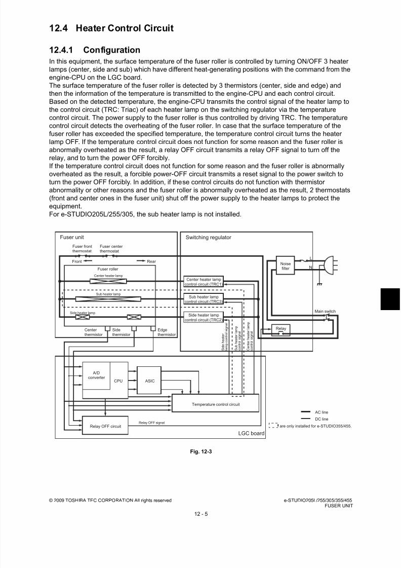
8/17/2019 Toshiba ES455 Service Manual
http://slidepdf.com/reader/full/toshiba-es455-service-manual 265/335
© 2009 TOSHIBA TEC CORPORATION All rights reserved e-STUDIO205L/255/305/355/455FUSER UNIT
12 - 5
12.4 Heater Control Circuit
12.4.1 Configuration
In this equipment, the surface temperature of the fuser roller is controlled by turning ON/OFF 3 heater
lamps (center, side and sub) which have different heat-generating positions with the command from the
engine-CPU on the LGC board.
The surface temperature of the fuser roller is detected by 3 thermistors (center, side and edge) and
then the information of the temperature is transmitted to the engine-CPU and each control circuit.
Based on the detected temperature, the engine-CPU transmits the control signal of the heater lamp tothe control circuit (TRC: Triac) of each heater lamp on the switching regulator via the temperature
control circuit. The power supply to the fuser roller is thus controlled by driving TRC. The temperature
control circuit detects the overheating of the fuser roller. In case that the surface temperature of the
fuser roller has exceeded the specified temperature, the temperature control circuit turns the heater
lamp OFF. If the temperature control circuit does not function for some reason and the fuser roller is
abnormally overheated as the result, a relay OFF circuit transmits a relay OFF signal to turn off the
relay, and to turn the power OFF forcibly.
If the temperature control circuit does not function for some reason and the fuser roller is abnormally
overheated as the result, a forcible power-OFF circuit transmits a reset signal to the power switch to
turn the power OFF forcibly. In addition, if these control circuits do not function with thermistor
abnormality or other reasons and the fuser roller is abnormally overheated as the result, 2 thermostats
(front and center ones in the fuser unit) shut off the power supply to the heater lamps to protect theequipment.
For e-STUDIO205L/255/305, the sub heater lamp is not installed.
Fig. 12-3
Relay OFF circuit
Temperature control circuit
A/Dconverter
Center heater lamp
Fuser roller
Fuser frontthermostat
Fuser centerthermostat
Edgethermistor
Sidethermistor
Center thermistor
Noisefilter
Main switch
AC line
DC line
Relay
Fuser unit
Relay OFF signal
LGC board
L
N
Switching regulator
Front Rear
CPU
S i d e h e a t e r
l a m p c o n t r o l s i g n a l
C e n t e r h e a t e r l a m p
c o n t r o l s i g n a l
Sub heater lampcontrol circuit (TRC3)
ASIC
are only installed for e-STUDIO355/455.
Sub heater lamp
Center heater lamp
control circuit (TRC1)
Side heater lamp
control circuit (TRC2)
S u b h e a t e r l a m p
c o n t r o l s i g n a l
Side heater lamp

8/17/2019 Toshiba ES455 Service Manual
http://slidepdf.com/reader/full/toshiba-es455-service-manual 266/335
e-STUDIO205L/255/305/355/455 © 2009 TOSHIBA TEC CORPORATION All rights reservedFUSER UNIT
12 - 6
12.4.2 Temperature detection section
To maintain the surface temperature of the fuser roller at a certain level, 3 thermistors (center, side and
edge) detect the surface temperature of the fuser roller to turn ON/OFF and control 3 heater lamps
(center, side and sub).
For e-STUDIO205L/255/305, the sub heater lamp is not installed.
1. Relation between the thermistor output voltage and surface temperature of the fuser roller
2. Control of the surface temperature of the fuser roller
Fig. 12-4
3. Temperature control for the both ends of the fuser roller
During continuous printing, the temperature of the end of the fuser roller (area where the paper does
not pass on) generally tends to be higher than that of other areas (areas where the paper passes
on). For this reason, the edge thermistor detects the temperature of the end of the fuser roller. When
this thermistor detects the abnormal temperature (230°C), the heater lamp is turned OFF regardless
of the temperature of the area where the paper passes on.
Output voltages of thermistors [V] Surface temperatures of fuser roller [ºC] Approx. 0.3 40
Approx. 1.2 100
Approx. 2.4 180
0
Heater lampON
°C
180
[185]
Temperature
of fuser roller OFF ON OFF ON OFF ON OFF OFFON ON
Ready(190°C [180°C]) During printing(190°C [180°C])
* [ ] are for e-STUDIO205L/255/305.
Warming-up
(180°C [160°C])

8/17/2019 Toshiba ES455 Service Manual
http://slidepdf.com/reader/full/toshiba-es455-service-manual 267/335

8/17/2019 Toshiba ES455 Service Manual
http://slidepdf.com/reader/full/toshiba-es455-service-manual 268/335
e-STUDIO205L/255/305/355/455 © 2009 TOSHIBA TEC CORPORATION All rights reservedFUSER UNIT
12 - 8
5. Fuser unit error status counter control
- To enhance the safety of the fusing section unit, engine-CPU provides the following protection:
When the third [C410] error has occurred after two consecutive [C410] errors, the heater lamp is
not turned ON and error [C410] is displayed immediately even if an operator turns OFF the
power and back ON. However, if the equipment goes into a ready state normally with the fuser
unit error status counter "1" or below, the counter is cleared to "0".
- If the error codes [C410] and [C430] to [C450] are displayed and still not cleared even though the
thermistor, thermostat and heater lamp have been repaired (and the power ON/OFF does notclear the error), check the Setting Mode (08-400) to set the fuser unit error status counter to "0".
Remark:The fuser unit error status counter (Setting Mode (08-400)) never has values other than 0-9.
• If the heater lamp does not turn ON and the service call [C410] is displayed immediately after
the power is ON, ensure the fuser unit error status counter is "2" or over. If it is "2" or over, be
sure to check the thermistor, thermostat and heater lamp. Reset the counter to "0" after
repairing them, then turn ON the power.
• If the fuser unit error status counter is "20" or over (e.g., 21), the data in EEPROM or
EEPROM itself may possibly have been ruined due to causes such as leakage from the
chargers.
Check the bias, high-voltage transformers and charge wires to see if any of them is defective,and also look through all the data in the EEPROM.
• When the thermistors detect overheating, the engine-CPU decides the error code and
counter value of the fuser unit error status. After turning OFF each output (the heater lamp,
exposure lamp, control panel display, motors and so on), the engine-CPU turns OFF the
power to protect the fuser unit.
Error code: C440 ([C] and [9])
Counter value of the fuser unit error status: 9 (08-400)
Thermistors continue detecting the abnormal temperature even after the error codes and
counter values are decided. Even if the power is turned ON immediately, it is automatically
turned OFF again when the surface temperature of the fuser roller is still higher than the
abnormal temperature detected.
Wait until the surface temperature of the fuser roller is lowered enough, and turn ON the
power to check the counter value while it is turned OFF again. After confirming that it is the
fuser unit abnormality, correct the abnormality and reset the counter value (08-400) to "0" to
start up the equipment normally.
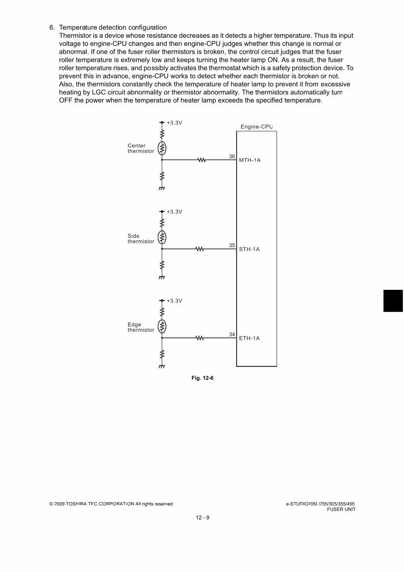
8/17/2019 Toshiba ES455 Service Manual
http://slidepdf.com/reader/full/toshiba-es455-service-manual 269/335
© 2009 TOSHIBA TEC CORPORATION All rights reserved e-STUDIO205L/255/305/355/455FUSER UNIT
12 - 9
6. Temperature detection configuration
Thermistor is a device whose resistance decreases as it detects a higher temperature. Thus its input
voltage to engine-CPU changes and then engine-CPU judges whether this change is normal or
abnormal. If one of the fuser roller thermistors is broken, the control circuit judges that the fuser
roller temperature is extremely low and keeps turning the heater lamp ON. As a result, the fuser
roller temperature rises, and possibly activates the thermostat which is a safety protection device. To
prevent this in advance, engine-CPU works to detect whether each thermistor is broken or not.
Also, the thermistors constantly check the temperature of heater lamp to prevent it from excessive
heating by LGC circuit abnormality or thermistor abnormality. The thermistors automatically turn
OFF the power when the temperature of heater lamp exceeds the specified temperature.
Fig. 12-6
35
36MTH-1A
STH-1A
Engine-CPU
Center thermistor
Sidethermistor
Edgethermistor
+3.3V
34ETH-1A
+3.3V
+3.3V

8/17/2019 Toshiba ES455 Service Manual
http://slidepdf.com/reader/full/toshiba-es455-service-manual 270/335
e-STUDIO205L/255/305/355/455 © 2009 TOSHIBA TEC CORPORATION All rights reservedFUSER UNIT
12 - 10
7. Abnormality detection by the thermistors
The following table shows the conditions judging the fuser roller temperature abnormality and
detecting timing.
* The figures in the “priority” section denote the priority of error checking.
Checking
timing
Prio
rity
Temperature judged Error-
judging
timing
Error
codeCenter
thermistor
Side
thermistor
Edge
thermistor
Power ON 1240°C or above - - Power ON C440
- 240°C or above -
Detecting 40°C
1240°C or above - - On usual C440
- 240°C or above -
240°C or below - - Specified
timeC410
- 40°C or below -
Detecting 100°C
1240°C or above - - On usual C440
- 240°C or above -
240°C or below 150°C or above - During
warming-up status
C430
150°C or above 40°C or below -
3100°C or below - - Specified
timeC440
- 100°C or below
Detecting readytemperature
1 240°C or above - - On usual C440- 240°C or above -
2
40°C or below 150°C or above - Duringwarming-up status
C430
150°C or above 40°C or below -
- 150°C or above 40°C or below
3
Ready temp. orbelow
- - Specifiedtime
C440
- Ready temp. orbelow
During ready status
1240°C or above - - On usual C440
- 240°C or above -
2
40°C or below 150°C or above - During
readystatus
C430
150°C or above 40°C or below -
- 150°C or above 40°C or below
340°C or below - - During
readystatus
C440
- 40°C or below -
During printing
1
240°C or above - - On usual C440
- 240°C or above -
- - 240°C or above
40°C or below - - Duringprinting- 40°C or below -
2 - - 40°C or below Duringprinting
C450
In Energy SavingMode
1240°C or above - - On usual C440
- 240°C or below -
At paper jam1 240°C or above - - On usual C440
- 240°C or below -
In Self-diagnosisMode
1240°C or above - - On usual C440
- 240°C or below -
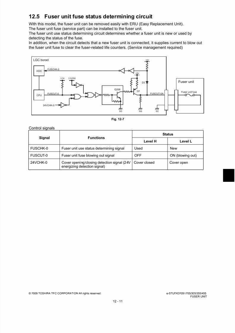
8/17/2019 Toshiba ES455 Service Manual
http://slidepdf.com/reader/full/toshiba-es455-service-manual 271/335
© 2009 TOSHIBA TEC CORPORATION All rights reserved e-STUDIO205L/255/305/355/455FUSER UNIT
12 - 11
12.5 Fuser unit fuse status determining circuit
With this model, the fuser unit can be removed easily with ERU (Easy Replacement Unit).
The fuser unit fuse (service part) can be installed to the fuser unit.
The fuser unit use status determining circuit determines whether a fuser unit is new or used by
detecting the status of the fuse.
In addition, when the circuit detects that a new fuser unit is connected, it supplies current to blow out
the fuser unit fuse to clear the fuser-related life counters. (Service management required)
Fig. 12-7
Control signals
Signal FunctionsStatus
Level H Level L
FUSCHK-0 Fuser unit use status determining signal Used New
FUSCUT-0 Fuser unit fuse blowing out signal OFF ON (blowing out)
24VCHK-0 Cover opening/closing detection signal (24Venergizing detection signal)
Cover closed Cover open
LGC borad
FUSCHK-0
FUSCUT-0
+5V
+5V
FUSCUT-0AQ1
D3
Q206
SGSGSG
24VCHK-0
ASIC
CPU
3.3VSW3.3V
Fuser unit
Fuser unit fuse
8/17/2019 Toshiba ES455 Service Manual
http://slidepdf.com/reader/full/toshiba-es455-service-manual 272/335
e-STUDIO205L/255/305/355/455 © 2009 TOSHIBA TEC CORPORATION All rights reservedFUSER UNIT
12 - 12
Notes:• C4C0 error occurs when it can not blow out the fuser unit fuse even if it detects a new fuser
unit.
• Confirm if 08-4549 is "0" when the counter is not cleared even if a new fuser unit is
connected.
When it is "1", change it to "0" and confirm the counter again after turning the power off and
on.
08-4549 (Detection setting of new or old fuser unit) 0: Valid 1:Invalid
• When replacing supplies without installing the fuser unit fuse, clear the fuser-related life
counters in the PM support mode written in chapter 5.
• The life counters which will be cleared when the fuser unit fuse is blown out are as follows in
the table below.
- Fuser roller counter 08-1246
- Pressure roller counter 08-1250
- Fuser roller separation finger counter 08-1268
- Heater and energizing time accumulating counter 08-1372
- Counter for period of time fuser unit is at ready temperature 08-1378
- Counter for period of time fuser unit is at printing temperature 08-1380
- Counter for period of time fuser unit is at energy saving temperature 08-1382- Number of output pages (Thick paper 1) 08-1385
- Number of output pages (Thick paper 1) 08-1385
- Number of output pages (Thick paper 2) 08-1386
- Number of output pages (Thick paper 3) 08-1387
- Number of output pages (OHP film) 08-1388
- Counter for envelopes 08-1411
- Counter for tab paper 08-1412

8/17/2019 Toshiba ES455 Service Manual
http://slidepdf.com/reader/full/toshiba-es455-service-manual 273/335
© 2009 TOSHIBA TEC CORPORATION All rights reserved e-STUDIO205L/255/305/355/455FUSER UNIT
12 - 13
12.6 Disassembly and Replacement
12.6.1 Fuser unit
12.6.2 Fuser roller unit / Pressure roller unit
(1) Open the small right rear cover.
(2) Loosen 2 screws and take off the fuser unit.
Note:
Be careful when handling the fuser unit as itmay become very hot.
Fig. 12-8
(1) Take off the fuser unit
( P.12-13 "12.6.1 Fuser unit").
(2) Remove 1 screw and take off the rear cover.
Disconnect 1 connector.
Note:When installing the rear cover, make sure
that the harness is not caught.
Fig. 12-9
(3) Remove 2 screws and take off the fuser
roller unit and the pressure roller unit.
Note:When installing, be sure to release the
pressure release lever.
Fig. 12-10
Fuser unit
Small right
rear cover
Rear cover
Connector
Fuser roller unit
Pressure roller unit
Pressure release lever Release
Release
Pressurerelease lever

8/17/2019 Toshiba ES455 Service Manual
http://slidepdf.com/reader/full/toshiba-es455-service-manual 274/335
e-STUDIO205L/255/305/355/455 © 2009 TOSHIBA TEC CORPORATION All rights reservedFUSER UNIT
12 - 14
12.6.3 Separation finger
12.6.4 Fuser roller
(1) Take off the fuser roller unit
( P.12-13 "12.6.2 Fuser roller unit /
Pressure roller unit").
(2) Remove 5 springs and take off 5 separation
fingers.
Fig. 12-11
(1) Take off the separation fingers
( P.12-14 "12.6.3 Separation finger").
(2) Remove 6 screws and take off the fuser
roller and three heater lamps.
Notes:1. Be careful not to deform the fuser roller
by pushing strongly.
2. When installing the heater lamps, refer to
the installation procedure.( P.12-15 "12.6.5 Heater lamp")
3. For e-STUDIO205L/255/305, the sub
heater lamp is not installed.
4. When installing the fuser roller, be careful
not to deform the thermistor.
5. When installing the fuser roller, confirm
that the drive gears are engaged. Fig. 12-12
(3) Remove 1 C-ring and 1 bearing from the
fuser roller front side.
(4) Remove 1 C-ring, 1 gear and 1 bearing from
the fuser roller rear side.
Fig. 12-13
Spring
Separation finger
Fuser roller
WhiteBlue
White
Side Sub
Center
C-ring
Bearing
C-ring
Gear
Bearing

8/17/2019 Toshiba ES455 Service Manual
http://slidepdf.com/reader/full/toshiba-es455-service-manual 275/335
© 2009 TOSHIBA TEC CORPORATION All rights reserved e-STUDIO205L/255/305/355/455FUSER UNIT
12 - 15
12.6.5 Heater lamp
(1) Take off the separation fingers
( P.12-14 "12.6.3 Separation finger").
(2) Remove 2 screws of each lamp, and then
take off the center heater lamp, side heater
lamp, sub heater lamp and fuser roller.
Notes:
1. When fixing the screws, do not mix up thetypes of screws.
2. When installing the heater lamps, do not
mix up the types of heater lamps.The shapes and screw holes of each
lamp vary. Install the heater lamps while
referring to the figure at right.
3. Install the heater lamps on their welded
sides on upper.
4. Make sure to connect the white lines to
the center heater lamp and side heater
lamp, and the blue line to the sub heater
lamp.
5. For e-STUDIO205L/255/305, the sub
heater lamp is not installed.
6. Be careful not to deform the fuser roller
by pushing strongly.
Fig. 12-14
Fig. 12-15
Fig. 12-16
Fuser roller
WhiteBlue
White
Side Sub
Center
Side heater lamp Center heater lamp
Sub heater lamp
Weld
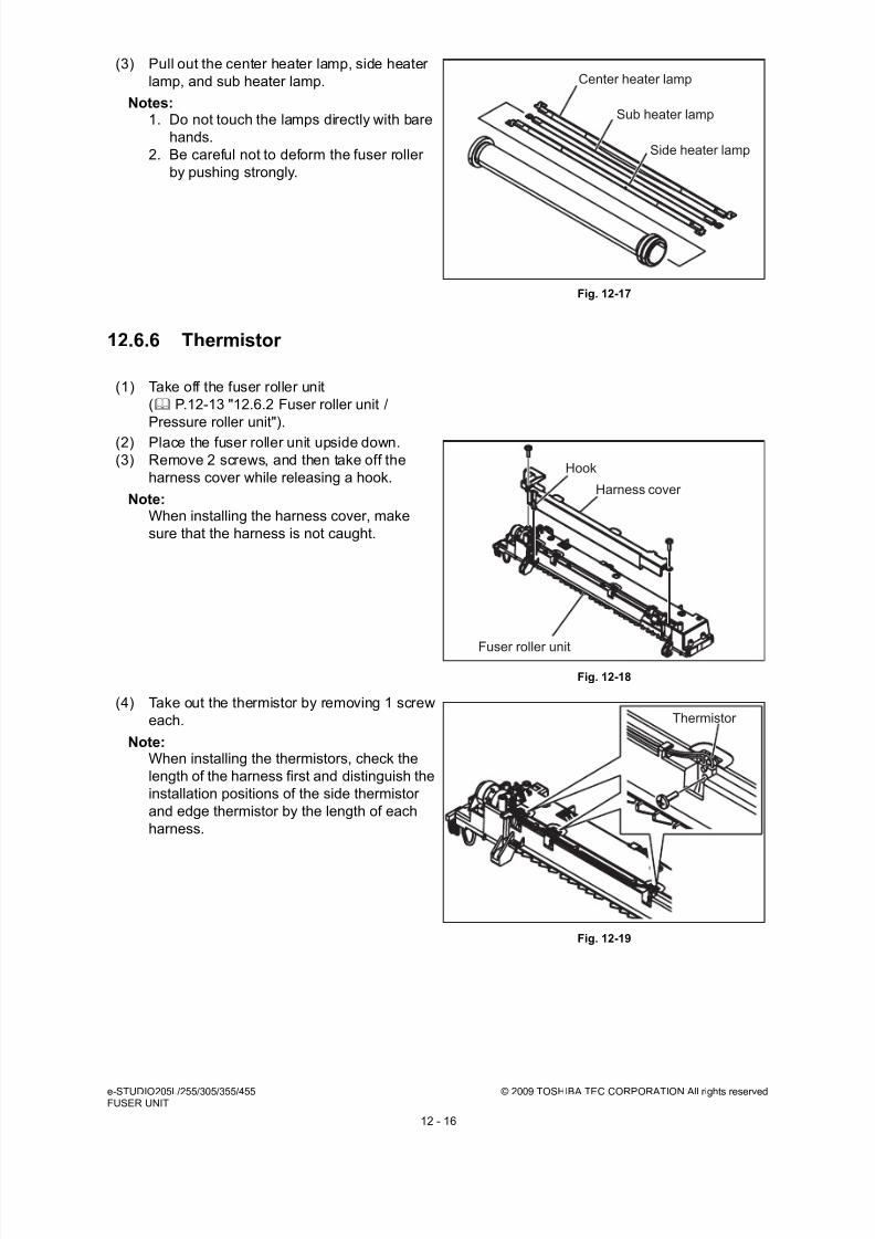
8/17/2019 Toshiba ES455 Service Manual
http://slidepdf.com/reader/full/toshiba-es455-service-manual 276/335
e-STUDIO205L/255/305/355/455 © 2009 TOSHIBA TEC CORPORATION All rights reservedFUSER UNIT
12 - 16
12.6.6 Thermistor
(3) Pull out the center heater lamp, side heater
lamp, and sub heater lamp.
Notes:1. Do not touch the lamps directly with bare
hands.
2. Be careful not to deform the fuser roller
by pushing strongly.
Fig. 12-17
(1) Take off the fuser roller unit
( P.12-13 "12.6.2 Fuser roller unit /
Pressure roller unit").
(2) Place the fuser roller unit upside down.
(3) Remove 2 screws, and then take off the
harness cover while releasing a hook.
Note:When installing the harness cover, make
sure that the harness is not caught.
Fig. 12-18
(4) Take out the thermistor by removing 1 screw
each.
Note:When installing the thermistors, check the
length of the harness first and distinguish the
installation positions of the side thermistor
and edge thermistor by the length of each
harness.
Fig. 12-19
Center heater lamp
Sub heater lamp
Side heater lamp
Hook
Harness cover
Fuser roller unit
Thermistor
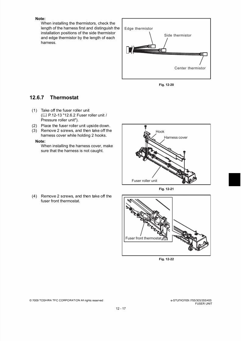
8/17/2019 Toshiba ES455 Service Manual
http://slidepdf.com/reader/full/toshiba-es455-service-manual 277/335
© 2009 TOSHIBA TEC CORPORATION All rights reserved e-STUDIO205L/255/305/355/455FUSER UNIT
12 - 17
12.6.7 Thermostat
Note:When installing the thermistors, check the
length of the harness first and distinguish the
installation positions of the side thermistor
and edge thermistor by the length of each
harness.
Fig. 12-20
(1) Take off the fuser roller unit
( P.12-13 "12.6.2 Fuser roller unit /
Pressure roller unit").(2) Place the fuser roller unit upside down.
(3) Remove 2 screws, and then take off the
harness cover while holding 2 hooks.
Note:When installing the harness cover, make
sure that the harness is not caught.
Fig. 12-21
(4) Remove 2 screws, and then take off the
fuser front thermostat.
Fig. 12-22
Center thermistor
Side thermistor
Edge thermistor
Hook
Harness cover
Fuser roller unit
Fuser front thermostat

8/17/2019 Toshiba ES455 Service Manual
http://slidepdf.com/reader/full/toshiba-es455-service-manual 278/335
e-STUDIO205L/255/305/355/455 © 2009 TOSHIBA TEC CORPORATION All rights reservedFUSER UNIT
12 - 18
(5) Remove 1 screw, and then take off the
thermostat cover.
Fig. 12-23
(6) Remove 2 screws, and then take off the
fuser center thermostat.
Fig. 12-24
Note:Wire the harness as shown in the figure and
fix it with clamp securely.
Fig. 12-25
Thermostat cover
Fuser center thermostat
Harness Thermostat

8/17/2019 Toshiba ES455 Service Manual
http://slidepdf.com/reader/full/toshiba-es455-service-manual 279/335
© 2009 TOSHIBA TEC CORPORATION All rights reserved e-STUDIO205L/255/305/355/455FUSER UNIT
12 - 19
12.6.8 Pressure roller
(1) Take off the pressure roller unit
( P.12-13 "12.6.2 Fuser roller unit /
Pressure roller unit").
(2) Remove 3 screws and take off the entrance
guide.
Fig. 12-26
(3) Take off the front cover.
Fig. 12-27
(4) Disconnect 1 connector, and then take off the
fuse cover while holding a hook.
Fig. 12-28
Pressure roller unit
Entrance guide
Front cover
Fuse cover Hook

8/17/2019 Toshiba ES455 Service Manual
http://slidepdf.com/reader/full/toshiba-es455-service-manual 280/335
e-STUDIO205L/255/305/355/455 © 2009 TOSHIBA TEC CORPORATION All rights reservedFUSER UNIT
12 - 20
(5) Remove 2 springs of both front and rear
sides of the pressure roller unit.
Fig. 12-29
Note:When installing the spring, catch the spring
on the hook in the middle.
Fig. 12-30
(6) Remove 4 screws, and then take off 2
stoppers.
(7) Pull out the pressure roller.
Fig. 12-31
Spring
Front side
Hook
Rear side
Spring
Spring HookHook
Front Side Rear Side
Stopper
Stopper
Pressure roller
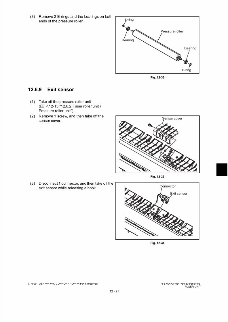
8/17/2019 Toshiba ES455 Service Manual
http://slidepdf.com/reader/full/toshiba-es455-service-manual 281/335
© 2009 TOSHIBA TEC CORPORATION All rights reserved e-STUDIO205L/255/305/355/455FUSER UNIT
12 - 21
12.6.9 Exit sensor
(8) Remove 2 E-rings and the bearings on both
ends of the pressure roller.
Fig. 12-32
(1) Take off the pressure roller unit
( P.12-13 "12.6.2 Fuser roller unit /
Pressure roller unit").(2) Remove 1 screw, and then take off the
sensor cover.
Fig. 12-33
(3) Disconnect 1 connector, and then take off the
exit sensor while releasing a hook.
Fig. 12-34
E-ring
E-ring
Bearing
Bearing
Pressure roller
Sensor cover
Connector
Exit sensor

8/17/2019 Toshiba ES455 Service Manual
http://slidepdf.com/reader/full/toshiba-es455-service-manual 282/335
e-STUDIO205L/255/305/355/455 © 2009 TOSHIBA TEC CORPORATION All rights reservedFUSER UNIT
12 - 22
12.6.10 Installation of the fuser unit fuse (service part)
Note:Wire the harness as shown in the figure and
fix it with clamp securely.
Fig. 12-35
(1) Take off the fuser unit
( P.12-13 "12.6.1 Fuser unit").
(2) Remove 1 screw and take off the rear cover.Disconnect 1 connector.
Note:When installing the rear cover, make sure
that the harness is not caught.
Fig. 12-36
(3) Connect the connectors of the fuser unit
fuse.
Fig. 12-37
Rear cover
Connector
Fuser unit fuse
Connector

8/17/2019 Toshiba ES455 Service Manual
http://slidepdf.com/reader/full/toshiba-es455-service-manual 283/335

8/17/2019 Toshiba ES455 Service Manual
http://slidepdf.com/reader/full/toshiba-es455-service-manual 284/335
e-STUDIO205L/255/305/355/455 © 2009 TOSHIBA TEC CORPORATION All rights reservedPAPER EXIT SECTION/REVERSE SECTION
13 - 2
13.2 Functions1. Exit motor
The exit motor is a stepping motor which drives the exit roller. For e-STUDIO205L/255/305, this
motor rotates exit roller reversely to switchback when the paper is transported to the ADU.
2. Exit roller
The exit roller transports the paper from the fuser unit to the inner tray. This roller is driven by the
exit motor.
For e-STUDIO205L/255/305, this roller switchbacks to transport the paper to the ADU.For e-STUDIO355/455, the exit roller has the offset function.
3. Reverse sensor (only installed for e-STUDIO355/455)
The reverse sensor detects if the leading edge of the paper from the paper exit section has reached
to the exit roller. This sensor is also used for the detection of a paper jam in the reverse section, and
the detection of the trailing edge of the reversed paper at duplex printing as well.
4. Reverse motor (only installed for e-STUDIO355/455)
The reverse motor is a stepping motor which drives the reverse roller, however, this motor rotates
reversely to switchback when the paper is transported to the upper exit area.
5. Reverse roller (only installed for e-STUDIO355/455)
The reverse roller transports the paper from the paper exit section to the job separator (MJ-5006) or ADU. This roller is driven by the reverse motor.
6. Offset gate motor (only installed for e-STUDIO355/455)
This offset gate motor drives the offset gate and shift the paper exit position back and forth.
7. Offset gate home position sensor (only installed for e-STUDIO355/455)
This offset gate home position sensor detects if the offset gate driven is back in the home position.
8. Reverse gate solenoid (only installed for e-STUDIO355/455)
This reverse gate solenoid drives the reverse gate and switches the paper transport path (exit
section of reverse section).

8/17/2019 Toshiba ES455 Service Manual
http://slidepdf.com/reader/full/toshiba-es455-service-manual 285/335
© 2009 TOSHIBA TEC CORPORATION All rights reserved e-STUDIO205L/255/305/355/455PAPER EXIT SECTION/REVERSE SECTION
13 - 3
13.3 Control Circuit of Exit Motor / Reverse Motor / Offset Gate
Motor 1. Exit Motor
The following is the control circuit of the exit motor.
The exit motor is a stepping motor.
It is driven by the pulse signals (EXTM+A, EXTM-A, EXTM+B, EXTM-B) output by the motor driver.
These pulse signals are generated by the reference clock (EXTMCK-1) from the ASIC, and output
only when the enable signal (EXTMEN-1) is at level "H".
The direction and speed of its rotation is switched by changing the output timing of each pulsesignal.
EXTVR-1 is the reference voltage for the current control of the motor.
Fig. 13-2
Control signals
* CW: rotates clockwise from the rotating shaft side, CCW: rotates counterclockwise
2. Reverse Motor (only installed for e-STUDIO355/455)
The following is the control circuit of the reverse motor which drives the reverse roller.
The reverse motor is a stepping motor.
It is driven by the pulse signals (REVM+A, REVM-A, REVM+B, REVM-B) output by the motor driver.
These pulse signals are generated by the reference clock (REVMCK-1) from the ASIC, and output
only when the enable signal (REVMEN-1) is at level "H".
The direction and speed of its rotation is switched by changing the output timing of each pulse
signal.
REVVR-1 is the reference voltage for the current control of the motor.
Signal FunctionsStatus
Level H Level L
EXTMCK-1 Reference clock - -
EXTMEN-1 Enable signal ON OFF
EXTMDIR-0 Rotation direction signal CCW CW
MOTRST-0 Reset signal Normal Reset
EXTVR-1 Reference voltage for the current control - -
ASIC
D/A
Converter
Motor
driver Exit motor
DACDT-1
DACLD-1 EXTVR-1
+5V +24V
DACCK-1
LGC board
MOT board (e-STUDIO205L/255/305)
MOT2 board (e-STUDIO355/455)
+24V
EXTMEN-1
MOTRST-0
EXTMDIR-0
EXTMCK-1
EXTM+A
EXTM-B
EXTM-A
EXTM+B
Reset signal
generation
circuit

8/17/2019 Toshiba ES455 Service Manual
http://slidepdf.com/reader/full/toshiba-es455-service-manual 286/335
e-STUDIO205L/255/305/355/455 © 2009 TOSHIBA TEC CORPORATION All rights reservedPAPER EXIT SECTION/REVERSE SECTION
13 - 4
Fig. 13-3
Control signals
* CW: rotates clockwise from the rotating shaft side, CCW: rotates counterclockwise
3. Offset gate motor (only installed for e-STUDIO355/455)
The following is the control circuit of the offset gate motor which drives the offset gate.
Fig. 13-4
Signal FunctionsStatus
Level H Level L
REVMCK-1 Reference clock - -
REVMEN-1 Enable signal ON OFF
REVMDIR-0 Rotation direction signal CCW CW
MOTRST-0 Reset signal Normal Reset
REVVR-1 Reference voltage for the current control - -
ASIC
D/A
Converter
Motor
driver Reverse
motor
DACDT-1
DACLD-1 REVVR-1
+5V +24V
DACCK-1
LGC board
MOT2 board
+24V
REVMEN-1
MOTRST-0
REVMDIR-0
REVMCK-1
REVM+A
REVM-B
REVM-A
REVM+B
Reset signal
generation
circuit
CS6/PC6
CS7/PC7
ASIC
OFFSET-2
Offset gate motor
OFFSET-1
OFFSET2
OFFSET1
F1
TA8428
IN2
IN1
OUT A
OUT A
LGC board MOT2 board

8/17/2019 Toshiba ES455 Service Manual
http://slidepdf.com/reader/full/toshiba-es455-service-manual 287/335
© 2009 TOSHIBA TEC CORPORATION All rights reserved e-STUDIO205L/255/305/355/455PAPER EXIT SECTION/REVERSE SECTION
13 - 5
13.4 Exit Motor / Reverse Motor / Offset Gate Motor Drive1. Exit Motor
The figure shown below is the layout of the driving gears of the exit roller.
Fig. 13-5
2. Reverse Motor (only installed for e-STUDIO355/455)
The figure shown below is the layout of the driving gears of the reverse roller.
Fig. 13-6
(G20)
Exit motor(P20)
(P40/G16)
Exit roller
Reverse
Forward
(G20)
(G27)
(G20)
(P40/G16)Reverse motor (P20)
Forward
Reverse Upper transport roller
Reverse roller
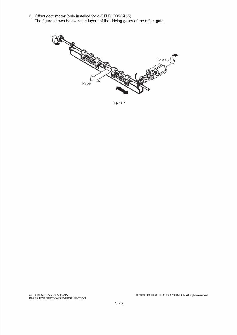
8/17/2019 Toshiba ES455 Service Manual
http://slidepdf.com/reader/full/toshiba-es455-service-manual 288/335
e-STUDIO205L/255/305/355/455 © 2009 TOSHIBA TEC CORPORATION All rights reservedPAPER EXIT SECTION/REVERSE SECTION
13 - 6
3. Offset gate motor (only installed for e-STUDIO355/455)
The figure shown below is the layout of the driving gears of the offset gate.
Fig. 13-7
Forward
Paper

8/17/2019 Toshiba ES455 Service Manual
http://slidepdf.com/reader/full/toshiba-es455-service-manual 289/335
© 2009 TOSHIBA TEC CORPORATION All rights reserved e-STUDIO205L/255/305/355/455PAPER EXIT SECTION/REVERSE SECTION
13 - 7
13.5 Disassembly and Replacement
13.5.1 Reverse unit (only installed for e-STUDIO355/455)
(1) Take off the fuser unit.
( P.12-13 "12.6.1 Fuser unit")
Note:
Be careful when handling the fuser unit as itmay become very hot.
(2) Remove 3 screws from the left side of the
reverse section, and then take off the cover.
Fig. 13-8
(3) Take off the connecting port cover.
( P.2-24 "2.5.12 Connecting port cover")
(4) Release the latches and take off the inner
cover.
Fig. 13-9
(5) Disconnect 1 connecter and remove 1 screw,
and take off the switch unit.
Fig. 13-10
Reverse section
Cover
latches
Inner cover
Connector
Switch unit
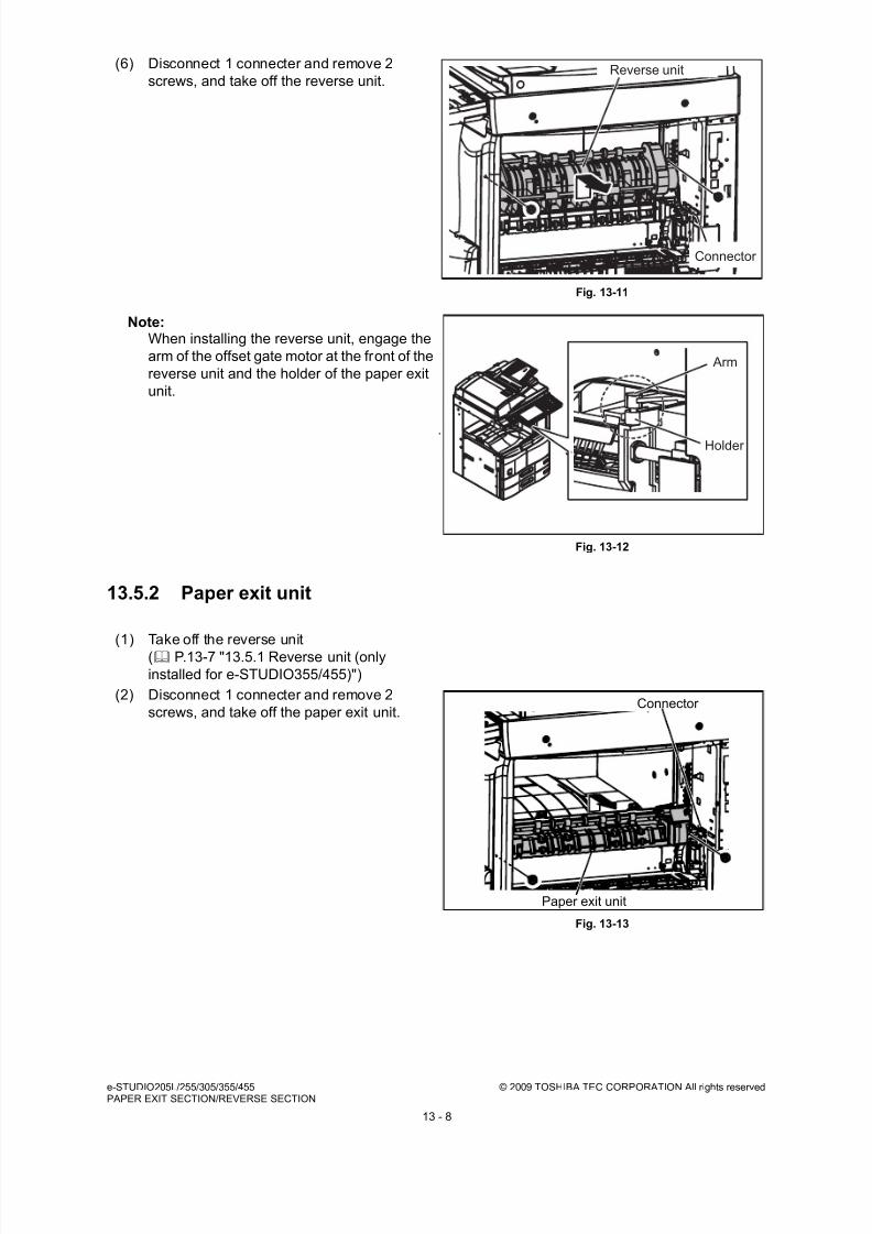
8/17/2019 Toshiba ES455 Service Manual
http://slidepdf.com/reader/full/toshiba-es455-service-manual 290/335
e-STUDIO205L/255/305/355/455 © 2009 TOSHIBA TEC CORPORATION All rights reservedPAPER EXIT SECTION/REVERSE SECTION
13 - 8
13.5.2 Paper exit unit
(6) Disconnect 1 connecter and remove 2
screws, and take off the reverse unit.
Fig. 13-11
Note:When installing the reverse unit, engage the
arm of the offset gate motor at the front of the
reverse unit and the holder of the paper exit
unit.
Fig. 13-12
(1) Take off the reverse unit
( P.13-7 "13.5.1 Reverse unit (only
installed for e-STUDIO355/455)")
(2) Disconnect 1 connecter and remove 2
screws, and take off the paper exit unit.
Fig. 13-13
Reverse unit
Connector
Arm
Holder
Paper exit unit
Connector
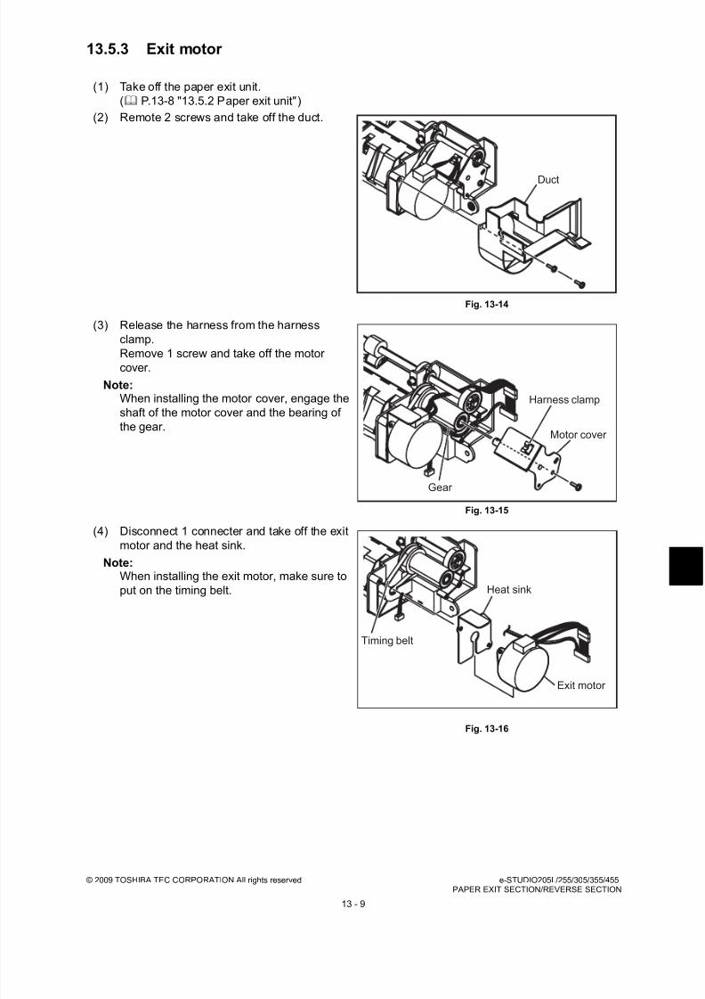
8/17/2019 Toshiba ES455 Service Manual
http://slidepdf.com/reader/full/toshiba-es455-service-manual 291/335
© 2009 TOSHIBA TEC CORPORATION All rights reserved e-STUDIO205L/255/305/355/455PAPER EXIT SECTION/REVERSE SECTION
13 - 9
13.5.3 Exit motor
(1) Take off the paper exit unit.
( P.13-8 "13.5.2 Paper exit unit")
(2) Remote 2 screws and take off the duct.
Fig. 13-14
(3) Release the harness from the harness
clamp.
Remove 1 screw and take off the motorcover.
Note:When installing the motor cover, engage the
shaft of the motor cover and the bearing of
the gear.
Fig. 13-15
(4) Disconnect 1 connecter and take off the exit
motor and the heat sink.
Note:When installing the exit motor, make sure to
put on the timing belt.
Fig. 13-16
Duct
Harness clamp
Motor cover
Gear
Timing belt
Exit motor
Heat sink

8/17/2019 Toshiba ES455 Service Manual
http://slidepdf.com/reader/full/toshiba-es455-service-manual 292/335
e-STUDIO205L/255/305/355/455 © 2009 TOSHIBA TEC CORPORATION All rights reservedPAPER EXIT SECTION/REVERSE SECTION
13 - 10
13.5.4 Offset gate home position sensor
13.5.5 Exit roller
(1) Take off the paper exit unit.
( P.13-8 "13.5.2 Paper exit unit")
(2) Disconnect 1 connector, release the latch
and take off the offset gate home position
sensor.
Fig. 13-17
(1) Take off the paper exit unit.
( P.13-8 "13.5.2 Paper exit unit")
(2) Remove 2 screws and take off the duct.
Fig. 13-18
(3) Release the harness from the harness
clamp.
Remove 1 screw and take off the motor
cover.
Note:When installing the motor cover, engage the
shaft of the motor cover and the bearing of
the gear.
Fig. 13-19
Offset gatehome positionsensor
Connector
Duct
Harness clamp
Motor cover
Gear
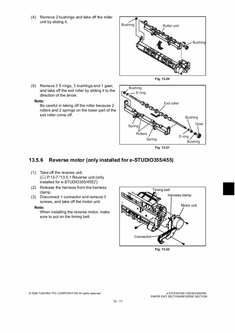
8/17/2019 Toshiba ES455 Service Manual
http://slidepdf.com/reader/full/toshiba-es455-service-manual 293/335
© 2009 TOSHIBA TEC CORPORATION All rights reserved e-STUDIO205L/255/305/355/455PAPER EXIT SECTION/REVERSE SECTION
13 - 11
13.5.6 Reverse motor (only installed for e-STUDIO355/455)
(4) Remove 2 bushings and take off the roller
unit by sliding it.
Fig. 13-20
(5) Remove 2 E-rings, 3 bushings and 1 gear,
and take off the exit roller by sliding it to the
direction of the arrow.
Note:Be careful in taking off the roller because 2
rollers and 2 springs on the lower part of the
exit roller come off.
Fig. 13-21
(1) Take off the reverse unit.
( P.13-7 "13.5.1 Reverse unit (only
installed for e-STUDIO355/455)")
(2) Release the harness from the harness
clamp.
(3) Disconnect 1 connector and remove 3
screws, and take off the motor unit.
Note:When installing the reverse motor, make
sure to put on the timing belt.
Fig. 13-22
Roller unit
Bushing
Bushing
Bushing
E-ring
Exit roller
Bushing
Gear
Bushing
E-ringSpring
Spring
Rollers
Timing belt
Harness clamp
Motor unit
Connector

8/17/2019 Toshiba ES455 Service Manual
http://slidepdf.com/reader/full/toshiba-es455-service-manual 294/335
e-STUDIO205L/255/305/355/455 © 2009 TOSHIBA TEC CORPORATION All rights reservedPAPER EXIT SECTION/REVERSE SECTION
13 - 12
13.5.7 Reverse gate solenoid (only installed for e-STUDIO355/455)
(4) Remove 2 screws and take off the reverse
motor.
Fig. 13-23
(1) Take off the reverse unit.
( P.13-7 "13.5.1 Reverse unit (only
installed for e-STUDIO355/455)")
(2) Remove 3 screws and take off the plate.
Note:When installing, engage the slit of the
reverse gate solenoid and the lever of the
gate.
Fig. 13-24
(3) Release the harness from the harness
clamp.
(4) Disconnect 1 connector and remove 2
screws, and take off the reverse gate
solenoid.
Fig. 13-25
Reverse motor
Reverse unit
Lever
Plate
Slit
Reverse gate solenoid
Connector
Harness clamp

8/17/2019 Toshiba ES455 Service Manual
http://slidepdf.com/reader/full/toshiba-es455-service-manual 295/335
© 2009 TOSHIBA TEC CORPORATION All rights reserved e-STUDIO205L/255/305/355/455PAPER EXIT SECTION/REVERSE SECTION
13 - 13
13.5.8 Reverse sensor (only installed for e-STUDIO355/455)
Notes:• Check the position of the scale before
taking off the solenoid.
• When installing the solenoid, match the
position of the scale to the previous
position.
Fig. 13-26
(1) Take off the reverse unit.
( P.13-7 "13.5.1 Reverse unit (only
installed for e-STUDIO355/455)")(2) Remove 3 screws and take off the plate.
Note:When installing, engage the slit of the
reverse gate solenoid and the lever of the
gate.
Fig. 13-27
(3) Disconnect 1 connector, release the latch,
and take off the reverse sensor.
Fig. 13-28
Reverse gate
solenoid
Window
Reverse unit
Lever
Plate
Slit
Reverse sensor
Connector
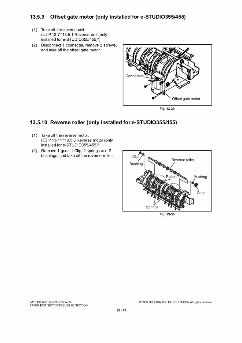
8/17/2019 Toshiba ES455 Service Manual
http://slidepdf.com/reader/full/toshiba-es455-service-manual 296/335
e-STUDIO205L/255/305/355/455 © 2009 TOSHIBA TEC CORPORATION All rights reservedPAPER EXIT SECTION/REVERSE SECTION
13 - 14
13.5.9 Offset gate motor (only installed for e-STUDIO355/455)
13.5.10 Reverse roller (only installed for e-STUDIO355/455)
(1) Take off the reverse unit.
( P.13-7 "13.5.1 Reverse unit (only
installed for e-STUDIO355/455)")
(2) Disconnect 1 connecter, remove 2 screws,
and take off the offset gate motor.
Fig. 13-29
(1) Take off the reverse motor.
( P.13-11 "13.5.6 Reverse motor (only
installed for e-STUDIO355/455)"
(2) Remove 1 gear, 1 Clip, 2 springs and 2
bushings, and take off the reverse roller.
Fig. 13-30
Offset gate motor
Connector
Bushing
Bushing
Reverse roller
Rollers
Gear
Springs
Clip

8/17/2019 Toshiba ES455 Service Manual
http://slidepdf.com/reader/full/toshiba-es455-service-manual 297/335
© 2009 TOSHIBA TEC CORPORATION All rights reserved e-STUDIO205L/255/305/355/455PAPER EXIT SECTION/REVERSE SECTION
13 - 15
13.5.11 Upper transport roller (only installed for e-STUDIO355/455)
(1) Take off the reverse motor.
( P.13-11 "13.5.6 Reverse motor (only
installed for e-STUDIO355/455)")
(2) Remove 1 gear, 1 clip and 2 bushings, and
take off the upper transport roller.
Fig. 13-31
Bushing
Gear
Upper transport roller Clip
Bushing

8/17/2019 Toshiba ES455 Service Manual
http://slidepdf.com/reader/full/toshiba-es455-service-manual 298/335
e-STUDIO205L/255/305/355/455 © 2009 TOSHIBA TEC CORPORATION All rights reservedPAPER EXIT SECTION/REVERSE SECTION
13 - 16

8/17/2019 Toshiba ES455 Service Manual
http://slidepdf.com/reader/full/toshiba-es455-service-manual 299/335
© 2009 TOSHIBA TEC CORPORATION All rights reserved e-STUDIO205L/255/305/355/455 AUTOMATIC DUPLEXING UNIT (ADU)
14 - 1
14. AUTOMATIC DUPLEXING UNIT (ADU)
14.1 General DescriptionThe Automatic Duplexing Unit (ADU) of this equipment is a unit to transport the paper, which is
switchbacked at the paper exit section/ reverse section and transported reversed, to the registration
roller again.
Fig. 14-1
ADU
ADU
Reverse roller
Reverse section
Exit roller
Paper exit section
Fuser section
Exit roller
Paper exit
section
Fuser section
ADU entrance sensor
ADU opening/closing switch
ADU upper transport roller
ADU lower transport roller
ADU clutch
ADU motor
ADU exit sensor
[ e-STUDIO355/455 ][ e-STUDIO205L/255/305 ]
8/17/2019 Toshiba ES455 Service Manual
http://slidepdf.com/reader/full/toshiba-es455-service-manual 300/335
e-STUDIO205L/255/305/355/455 © 2009 TOSHIBA TEC CORPORATION All rights reserved AUTOMATIC DUPLEXING UNIT (ADU)
14 - 2
14.2 Functions1. ADU motor (M5)
Drives the ADU upper transport roller and the ADU lower transport roller. The ADU motor is installed
to the rear frame of the equipment.
2. ADU clutch (CLT1)
Transmits the drive from the ADU motor (M5) to the ADU lower transport roller.
3. ADU entrance sensor (S11)Detects the paper transported in the ADU.
4. ADU exit sensor (S10)
Detects the paper transported in the ADU.
5. ADU opening/closing switch (SW5)
Detects opening/closing of the ADU.
6. ADU upper transport roller, ADU lower transport roller
Transports the paper inside the ADU.
8/17/2019 Toshiba ES455 Service Manual
http://slidepdf.com/reader/full/toshiba-es455-service-manual 301/335
© 2009 TOSHIBA TEC CORPORATION All rights reserved e-STUDIO205L/255/305/355/455 AUTOMATIC DUPLEXING UNIT (ADU)
14 - 3
14.3 Description of OperationsThe back side printing (recording data of the back side of paper) is performed first by selecting duplex
printing mode and pressing the [START] button.
Then for e-STUDIO355/455, when the paper passed the reverse sensor, the reverse gate solenoid
switches the reverse gate, and the reverse roller switchbacks to transport the paper into the ADU.
For e-STUDIO205L/255/305, when the paper passed the exit sensor, the exit roller switchbacks to
transport the paper into the ADU.
The switchbacked paper is transported with acceleration. The transportation decelerates in front of the ADU exit sensor. The front side printing (recording data of the front side of paper) is performed at the
registration section. The paper passes through the exit gate again and is transported to the inner tray to
complete duplex printing.
There are three methods of judging a paper jam: (1) whether the ADU entrance sensor is turned ON or
not in a specified period of time after the switchback to the ADU started (E510). (2) whether the ADU
exit sensor is turned ON or not in a specified period of time after the ADU entrance sensor is turned ON
(E520). (3) whether the registration sensor is turned ON or not in a specified period of time after the
paper feeding from the ADU to the equipment (E110).
If the ADU is opened during duplex printing, the ADU motor and ADU clutch are stopped, namely, ADU
open jam occurs (E430).
The equipment is never to be stopped during printing by interruption in any case except paper jam orservice call.
The operation of the duplex printing differs depending on the size of the paper; single-paper circulation
and alternateness circulation. The figures in the following pages show the circulating operations during
duplex copying. The numbers in the figures indicate the page numbers.

8/17/2019 Toshiba ES455 Service Manual
http://slidepdf.com/reader/full/toshiba-es455-service-manual 302/335
e-STUDIO205L/255/305/355/455 © 2009 TOSHIBA TEC CORPORATION All rights reserved AUTOMATIC DUPLEXING UNIT (ADU)
14 - 4
1. Single-paper circulation (e-STUDIO205L/255/305)
With the paper larger than A4 size, duplex printing (back-side printing .. front-side printing) is
performed for one sheet at a time as shown below.
Fig. 14-2
(1)
(4)
(7)
(2)
(5)
(8)
(3)
(6)
(9)
2
2
2
4
4
4
4
1
22
1
1
2
1
2
1
2
1
3
2
1
3
Exit section
4
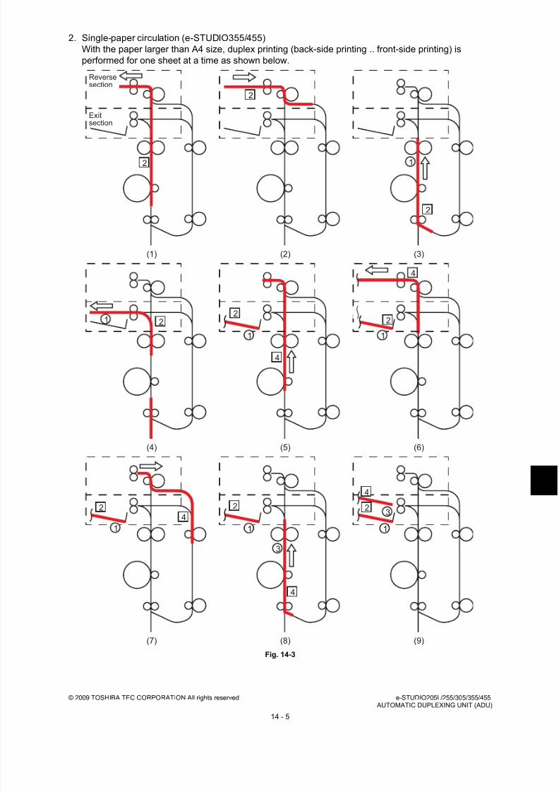
8/17/2019 Toshiba ES455 Service Manual
http://slidepdf.com/reader/full/toshiba-es455-service-manual 303/335
© 2009 TOSHIBA TEC CORPORATION All rights reserved e-STUDIO205L/255/305/355/455 AUTOMATIC DUPLEXING UNIT (ADU)
14 - 5
2. Single-paper circulation (e-STUDIO355/455)
With the paper larger than A4 size, duplex printing (back-side printing .. front-side printing) is
performed for one sheet at a time as shown below.
Fig. 14-3
Exitsection
Reversesection
(1)
(4)
(7)
(2)
(5)
(8)
(3)
(6)
(9)
2
2
2
4
4
4
4
1
22
1
1
2
1
2
1
2
1
3
2
1
3
4

8/17/2019 Toshiba ES455 Service Manual
http://slidepdf.com/reader/full/toshiba-es455-service-manual 304/335
e-STUDIO205L/255/305/355/455 © 2009 TOSHIBA TEC CORPORATION All rights reserved AUTOMATIC DUPLEXING UNIT (ADU)
14 - 6
3. Double-paper alternateness circulation (e-STUDIO205L/255/305)
With A4 size paper or smaller, duplex printing is performed for two sheets at a time as shown below.
Back side of the 1st sheet Back side of the 2nd sheet Front side of the 1st sheet Front side
of the 2nd sheet
Fig. 14-4
(1)
(4)
(7)
(2)
(5)
(8)
(3)
(6)
2
2
4
4
4
2
4
2
2
1
3
2
1
2
1
3
4
Exit section

8/17/2019 Toshiba ES455 Service Manual
http://slidepdf.com/reader/full/toshiba-es455-service-manual 305/335
© 2009 TOSHIBA TEC CORPORATION All rights reserved e-STUDIO205L/255/305/355/455 AUTOMATIC DUPLEXING UNIT (ADU)
14 - 7
4. Double-paper alternateness circulation (e-STUDIO355/455)
With A4 size paper or smaller, duplex printing is performed for two sheets at a time as shown below.
Back side of the 1st sheet Back side of the 2nd sheet Front side of the 1st sheet Front side
of the 2nd sheet
Fig. 14-5
2
2
4
4
4
2
4
2
2
1
3
2
1
2
1
3
4
(1)
(4)
(7)
(2)
(5)
(8)
(3)
(6)
Exit
section
Reversesection

8/17/2019 Toshiba ES455 Service Manual
http://slidepdf.com/reader/full/toshiba-es455-service-manual 306/335
e-STUDIO205L/255/305/355/455 © 2009 TOSHIBA TEC CORPORATION All rights reserved AUTOMATIC DUPLEXING UNIT (ADU)
14 - 8
14.4 Drive of ADUWhen the ADU motor rotates in the direction A, the ADU upper transport roller is rotated with the drive
of the gears and belt, and thus the paper is transported. When the ADU clutch is turned ON, the ADU
lower transport roller is rotated.
Fig. 14-6
ADU motor(21)
ADU clutch(G28)
A
(G15) (G28)
(G28)
ADU upper transport roller (G23)
(G39)
ADU lower transport roller
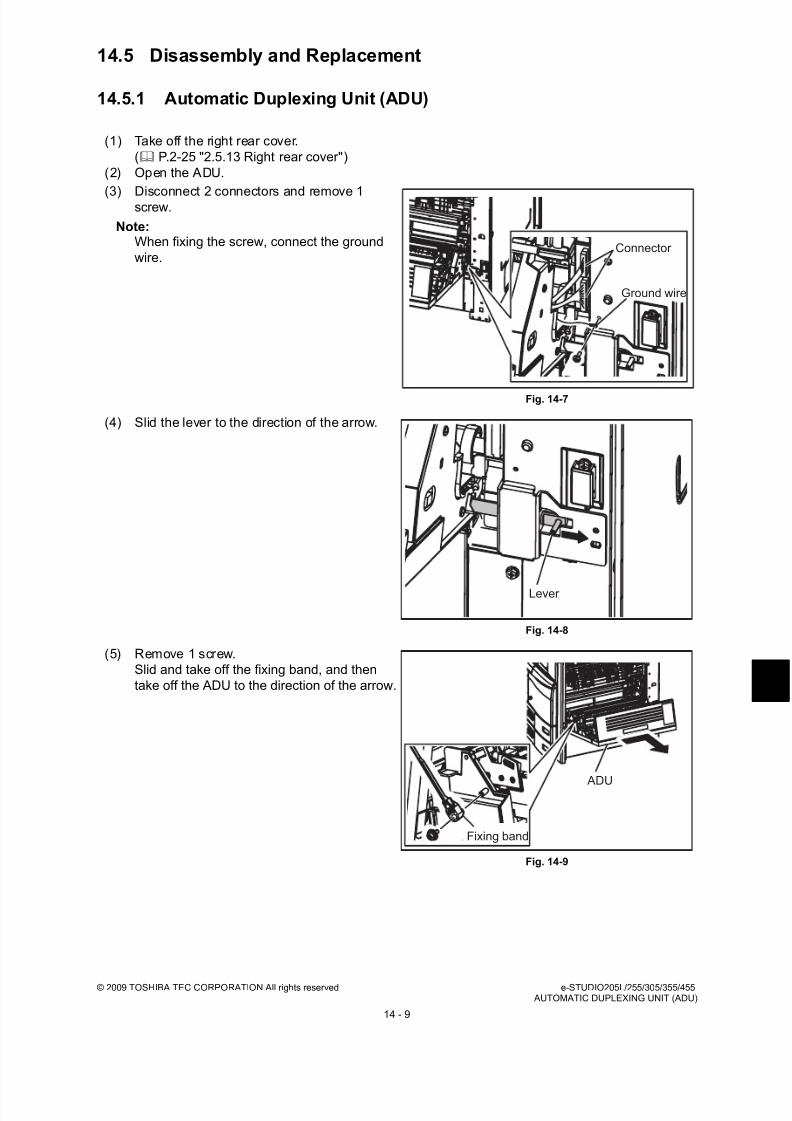
8/17/2019 Toshiba ES455 Service Manual
http://slidepdf.com/reader/full/toshiba-es455-service-manual 307/335
© 2009 TOSHIBA TEC CORPORATION All rights reserved e-STUDIO205L/255/305/355/455 AUTOMATIC DUPLEXING UNIT (ADU)
14 - 9
14.5 Disassembly and Replacement
14.5.1 Automatic Duplexing Unit (ADU)
(1) Take off the right rear cover.
( P.2-25 "2.5.13 Right rear cover")
(2) Open the ADU.
(3) Disconnect 2 connectors and remove 1screw.
Note:When fixing the screw, connect the ground
wire.
Fig. 14-7
(4) Slid the lever to the direction of the arrow.
Fig. 14-8
(5) Remove 1 screw.
Slid and take off the fixing band, and then
take off the ADU to the direction of the arrow.
Fig. 14-9
Connector
Ground wire
Lever
ADU
Fixing band

8/17/2019 Toshiba ES455 Service Manual
http://slidepdf.com/reader/full/toshiba-es455-service-manual 308/335

8/17/2019 Toshiba ES455 Service Manual
http://slidepdf.com/reader/full/toshiba-es455-service-manual 309/335
© 2009 TOSHIBA TEC CORPORATION All rights reserved e-STUDIO205L/255/305/355/455 AUTOMATIC DUPLEXING UNIT (ADU)
14 - 11
14.5.3 ADU exit sensor
(1) Take off the ADU.
( P.14-9 "14.5.1 Automatic Duplexing Unit
(ADU)").
(2) Remove 4 screws and take off the 2
brackets.
(3) Take off the transfer unit.
Fig. 14-13
(4) Disconnect 1 connector, remove 2 screws
and take off the bypass feed unit.
Fig. 14-14
(5) Remove 4 screws and the take off the ADU
lower guide.
Fig. 14-15
Bracket
Bracket
Transfer unit
Bypass feed unit
ADU lower guide Connector

8/17/2019 Toshiba ES455 Service Manual
http://slidepdf.com/reader/full/toshiba-es455-service-manual 310/335
e-STUDIO205L/255/305/355/455 © 2009 TOSHIBA TEC CORPORATION All rights reserved AUTOMATIC DUPLEXING UNIT (ADU)
14 - 12
14.5.4 ADU motor
(6) Disconnect 1 connector, release the latches
and take off the ADU exit sensor.
Fig. 14-16
(1) Take off the rear cover.
( P.2-22 "2.5.6 Rear cover")
(2) Disconnect 1 connector and remove 2
screws, and take off the ADU motor unit.
Fig. 14-17
(3) Loosen 1 screw.
Note:When installing the ADU motor, install the
ADU motor unit to the equipment, then close
the Automatic Duplexing Unit before
tightening this screw.
Fig. 14-18
ADU exitsensor
Connector
ADU motor unit
Connector
Screw
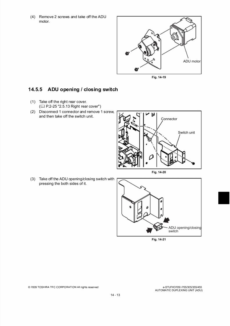
8/17/2019 Toshiba ES455 Service Manual
http://slidepdf.com/reader/full/toshiba-es455-service-manual 311/335
© 2009 TOSHIBA TEC CORPORATION All rights reserved e-STUDIO205L/255/305/355/455 AUTOMATIC DUPLEXING UNIT (ADU)
14 - 13
14.5.5 ADU opening / closing switch
(4) Remove 2 screws and take off the ADU
motor.
Fig. 14-19
(1) Take off the right rear cover.
( P.2-25 "2.5.13 Right rear cover")
(2) Disconnect 1 connector and remove 1 screw,
and then take off the switch unit.
Fig. 14-20
(3) Take off the ADU opening/closing switch with
pressing the both sides of it.
Fig. 14-21
ADU motor
Connector
Switch unit
ADU opening/closingswitch
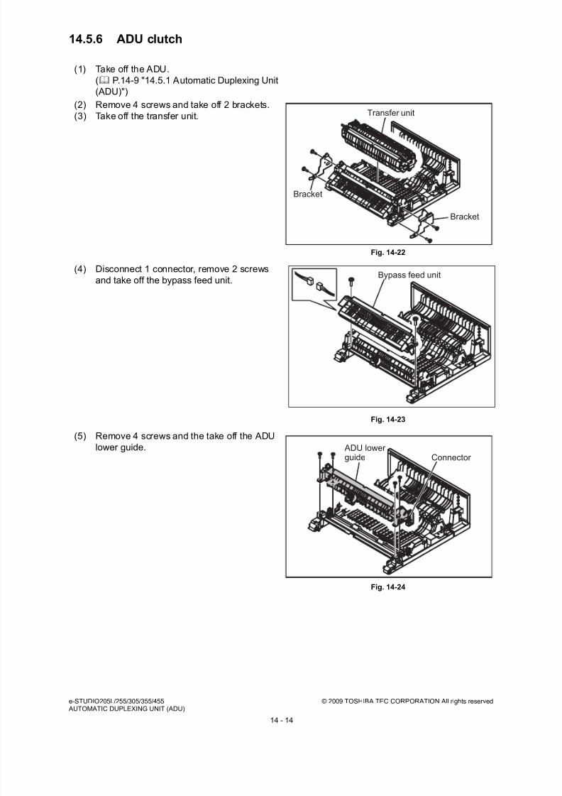
8/17/2019 Toshiba ES455 Service Manual
http://slidepdf.com/reader/full/toshiba-es455-service-manual 312/335
e-STUDIO205L/255/305/355/455 © 2009 TOSHIBA TEC CORPORATION All rights reserved AUTOMATIC DUPLEXING UNIT (ADU)
14 - 14
14.5.6 ADU clutch
(1) Take off the ADU.
( P.14-9 "14.5.1 Automatic Duplexing Unit
(ADU)")
(2) Remove 4 screws and take off 2 brackets.
(3) Take off the transfer unit.
Fig. 14-22
(4) Disconnect 1 connector, remove 2 screws
and take off the bypass feed unit.
Fig. 14-23
(5) Remove 4 screws and the take off the ADU
lower guide.
Fig. 14-24
Bracket
Bracket
Transfer unit
Bypass feed unit
ADU lower guide Connector
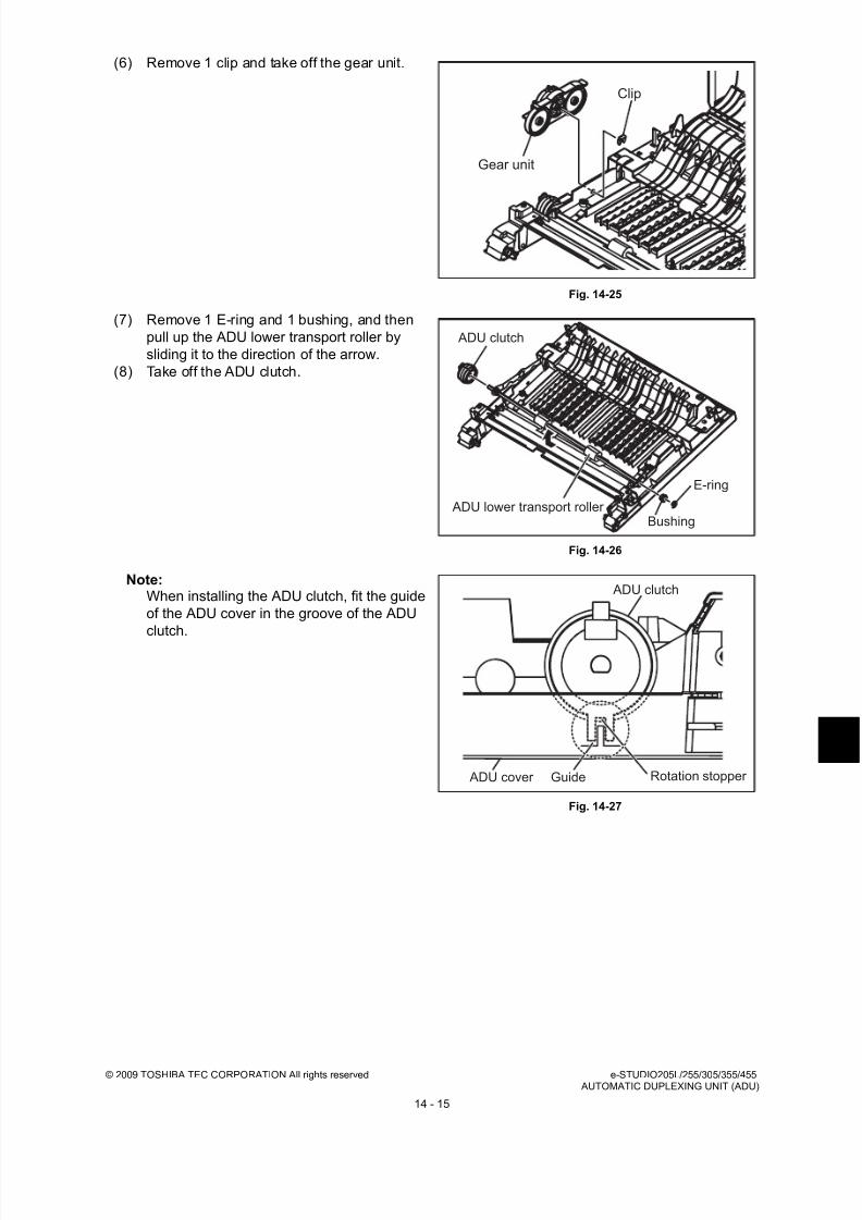
8/17/2019 Toshiba ES455 Service Manual
http://slidepdf.com/reader/full/toshiba-es455-service-manual 313/335
© 2009 TOSHIBA TEC CORPORATION All rights reserved e-STUDIO205L/255/305/355/455 AUTOMATIC DUPLEXING UNIT (ADU)
14 - 15
(6) Remove 1 clip and take off the gear unit.
Fig. 14-25
(7) Remove 1 E-ring and 1 bushing, and then
pull up the ADU lower transport roller by
sliding it to the direction of the arrow.
(8) Take off the ADU clutch.
Fig. 14-26
Note:When installing the ADU clutch, fit the guide
of the ADU cover in the groove of the ADU
clutch.
Fig. 14-27
Clip
Gear unit
ADU clutch
ADU lower transport roller
E-ring
Bushing
ADU clutch
Rotation stopper Guide ADU cover

8/17/2019 Toshiba ES455 Service Manual
http://slidepdf.com/reader/full/toshiba-es455-service-manual 314/335
e-STUDIO205L/255/305/355/455 © 2009 TOSHIBA TEC CORPORATION All rights reserved AUTOMATIC DUPLEXING UNIT (ADU)
14 - 16
14.5.7 ADU lower transport roller
14.5.8 ADU upper transport roller
(1) Take off the ADU clutch.
( P.14-14 "14.5.6 ADU clutch")
(2) Remove the ground plate, 1 E-ring and 1
bushing, and then take off the ADU lower
transport roller.
Fig. 14-28
(1) Take off the ADU.
( P.14-9 "14.5.1 Automatic Duplexing Unit
(ADU)")
(2) Remove 4 screws and take off 2 brackets.
(3) Take off the transfer unit.
Fig. 14-29
(4) Disconnect 1 connector, remove 2 screws
and take off the bypass feed unit.
Fig. 14-30
ADU lower transport roller
Bushing
E-ring
Ground plate
Bracket
Bracket
Transfer unit
Bypass feed unit

8/17/2019 Toshiba ES455 Service Manual
http://slidepdf.com/reader/full/toshiba-es455-service-manual 315/335
© 2009 TOSHIBA TEC CORPORATION All rights reserved e-STUDIO205L/255/305/355/455 AUTOMATIC DUPLEXING UNIT (ADU)
14 - 17
(5) Remove 4 screws and the take off the ADU
lower guide.
Fig. 14-31
(6) Remove 1 clip and take off the gear unit.
Fig. 14-32
(7) Disconnect 1 connector and remove 4
screws, and the take off the ADU upper
guide.
Fig. 14-33
(8) Remove 2 clips, 1 bushing, 1 gear, 1 pin and
the ground plate. Then take off the ADU
upper transport roller.Note:
When installing the gear, insert the pin in the
roller shaft and fit it in the groove of the gear.
Fig. 14-34
ADU lower guide Connector
Clip
Gear unit
ADU upper guide
Connector
Clip
Bushing
Pin
Bushing
Ground plateGear
Clip
ADU upper transport roller

8/17/2019 Toshiba ES455 Service Manual
http://slidepdf.com/reader/full/toshiba-es455-service-manual 316/335
e-STUDIO205L/255/305/355/455 © 2009 TOSHIBA TEC CORPORATION All rights reserved AUTOMATIC DUPLEXING UNIT (ADU)
14 - 18

8/17/2019 Toshiba ES455 Service Manual
http://slidepdf.com/reader/full/toshiba-es455-service-manual 317/335
© 2009 TOSHIBA TEC CORPORATION All rights reserved e-STUDIO205L/255/305/355/455POWER SUPPLY UNIT
15 - 1
15. POWER SUPPLY UNIT
15.1 ConstructionThe power supply unit consists of the AC filter, insulation type DC output circuit, heater lamp control
circuit and damp heater power supply circuit.
1. AC filter
Eliminates noise from the outside and prevents the noise generated by the equipment from leaking
to the outside.
2. DC output circuits
Converts AC voltage input from outside to DC voltage and supplies it to each electric part. The DC
voltage is divided into the following two lines.
a. Main switch line:Power supply used in the entire equipment during image forming process.
Two kinds of voltage (+5V, +12V) are output when the main switch of the
equipment is turned ON.
b. Door switch line :Power supply used in the entire equipment during image forming process, being
supplied via the interlock switch. Two kinds of voltage (+5VD and +24VD) are
output only when the main switch of the equipment is turned ON and two doors(front cover and ADU unit) are closed.
3. Heater lamp control circuit
TRC (Triac) is driven by the heater control signal (HTR1ON/HTR2ON/HTRASTON) from the LGC
board and then AC power is supplied to each heater lamp (center, side and sub) in the fuser unit.
For e-STUDIO205L/255/305, the sub heater lamp is not installed and the HTRASTON signal is not
supplied.
4. Damp heater power supply circuit
AC power input from outside is output directly to the FUS board and then supplied to the damp
heater in each section in the equipment. The damp heater switch is set to OFF as initial setting for
shutting off the power to the damp heater. When using the damp heater, the damp heater switchneeds to be turn ON after installing the equipment. The damp heater (including the FUS board) is an
option in NAD/MJD model, and is installed as standard device in other models.
8/17/2019 Toshiba ES455 Service Manual
http://slidepdf.com/reader/full/toshiba-es455-service-manual 318/335
e-STUDIO205L/255/305/355/455 © 2009 TOSHIBA TEC CORPORATION All rights reservedPOWER SUPPLY UNIT
15 - 2
15.2 Operation of DC Output Circuits1. Starting line output
When the main switch of the equipment is turned ON, power starts supplying to all the lines only
when two doors (front cover and ADU) are closed.
2. Stopping line output
When the main switch of the equipment is turned OFF, PWR-DN signal is output after the
instantaneous outage insurance time elapses and then the supply of each voltage stops. If the
supply of voltage of the main line (+5VS, +5VA, +12VA) stops earlier than the 24V line does, it maycause the damage of the electron device on each control circuit. To prevent this, the supply of these
voltages stops after the PWR-DN signal is output and the minimum retaining time elapses.
3. Output protection
Each output system includes an overcurrent and overvoltage protection circuits (a fuse and internal
protection circuit). This is to prevent the defectives (damage or abnormal operation of the secondary
circuit) which may be caused by an overcurrent due to a short circuit or an overvoltage due to a
short circuit between different voltages. If the protection circuit is activated (except the case the fuse
is blown out), remove the causes such as short-circuit. Turn ON the power again to clear the
overcurrent protection.
4. Recovering from super sleep mode (normal starting)
When the [ON/OFF] button on the control panel is pressed during the super sleep mode, a supersleep mode shifting/recovering signal (SYS-EN) is output from the SYS board and then voltage
starts being supplied to all the lines, if no error was detected.
5. Shifting to super sleep mode (normal stopping)
When the [ON/OFF] button on the control panel is pressed for 1 second or more while the main
switch of the equipment is toggled ON, a super sleep mode shifting/recovering signal (SYS-EN) is
output from the SYS board after the initialization is finished and then all lines for output voltage
except +5VS are closed.
The Super sleep mode is disabled under the following conditions.
- When the Super sleep mode is set to be disabled on the control panel, TopAccess and with thecode 08-8543
- When the Wireless LAN Module, Bluetooth Module, e-BRIDGE ID Gate or Data Overwrite
Enabler is installed, or when the IPsec Enabler is installed and its function is set to be enabled
- When the setting for receiving confidential data on each line (08-3846) is set to ON
- When operation is being performed in the self-diagnosis mode (Disabled until the main switch is
turned OFF)
6. State of the power supply
- Power OFF
The main switch of the equipment is turned OFF. Since DC voltage is not supplied to each board,
the equipment is not operable.
- Normal state (including Energy saving mode)
The main switch of the equipment is turned ON and DC voltage is supplied to each board. When
the cover of the equipment is closed, 24V DC voltage is supplied and the equipment enters into
the ready/printing state.
- Sleep mode
Since +5VB, +5VD, +12VB and +24V DC voltages are not supplied but +12VA, +5VA and +5VS
DC voltages only, the equipment does not enter into the ready state.

8/17/2019 Toshiba ES455 Service Manual
http://slidepdf.com/reader/full/toshiba-es455-service-manual 319/335
© 2009 TOSHIBA TEC CORPORATION All rights reserved e-STUDIO205L/255/305/355/455POWER SUPPLY UNIT
15 - 3
- Super Sleep mode
Only DC voltage and +5VS are output from the power supply unit. The [ON/OFF] button is
monitored and the LED of the main switch is lit.
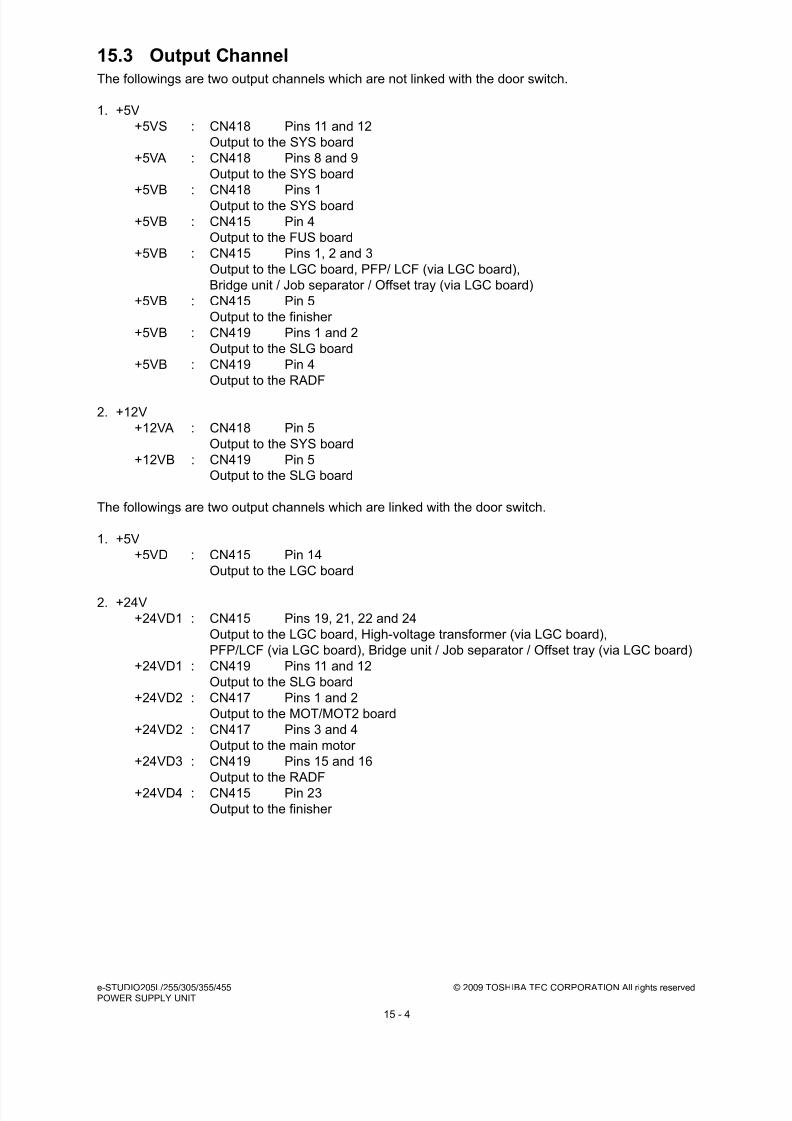
8/17/2019 Toshiba ES455 Service Manual
http://slidepdf.com/reader/full/toshiba-es455-service-manual 320/335
e-STUDIO205L/255/305/355/455 © 2009 TOSHIBA TEC CORPORATION All rights reservedPOWER SUPPLY UNIT
15 - 4
15.3 Output ChannelThe followings are two output channels which are not linked with the door switch.
1. +5V
+5VS : CN418 Pins 11 and 12
Output to the SYS board
+5VA : CN418 Pins 8 and 9
Output to the SYS board
+5VB : CN418 Pins 1Output to the SYS board
+5VB : CN415 Pin 4
Output to the FUS board
+5VB : CN415 Pins 1, 2 and 3
Output to the LGC board, PFP/ LCF (via LGC board),
Bridge unit / Job separator / Offset tray (via LGC board)
+5VB : CN415 Pin 5
Output to the finisher
+5VB : CN419 Pins 1 and 2
Output to the SLG board
+5VB : CN419 Pin 4
Output to the RADF
2. +12V
+12VA : CN418 Pin 5
Output to the SYS board
+12VB : CN419 Pin 5
Output to the SLG board
The followings are two output channels which are linked with the door switch.
1. +5V
+5VD : CN415 Pin 14
Output to the LGC board
2. +24V
+24VD1 : CN415 Pins 19, 21, 22 and 24
Output to the LGC board, High-voltage transformer (via LGC board),
PFP/LCF (via LGC board), Bridge unit / Job separator / Offset tray (via LGC board)
+24VD1 : CN419 Pins 11 and 12
Output to the SLG board
+24VD2 : CN417 Pins 1 and 2
Output to the MOT/MOT2 board
+24VD2 : CN417 Pins 3 and 4
Output to the main motor
+24VD3 : CN419 Pins 15 and 16
Output to the RADF
+24VD4 : CN415 Pin 23
Output to the finisher

8/17/2019 Toshiba ES455 Service Manual
http://slidepdf.com/reader/full/toshiba-es455-service-manual 321/335
© 2009 TOSHIBA TEC CORPORATION All rights reserved e-STUDIO205L/255/305/355/455POWER SUPPLY UNIT
15 - 5
<<Output connector>>
Not linked with the door switch
Linked with the door switch
Connector Destination Voltage
CN418 For the SYS board +5VS, +5VA, +5VB, +12VA
CN415 For the LGC board, FUS board, PFP/LCF (via LGCboard), Bridge unit / Job separator / Offset tray (viaLGC board), finisher
+5VB
CN419 For the SLG board, RADF +5VB, +12VB
Connector Destination Voltage
CN415 For the LGC board, High-voltage transformer (viaLGC board), PFP/LCF (via LGC board), Bridge unit /Job separator / Offset tray (via LGC board), finisher
+5VD, +24VD1, +24VD4
CN417 For the Main motor, MOT/MOT2 board +24VD2
CN419 For the SLG board, RADF +24VD1, +24VD3

8/17/2019 Toshiba ES455 Service Manual
http://slidepdf.com/reader/full/toshiba-es455-service-manual 322/335
e-STUDIO205L/255/305/355/455 © 2009 TOSHIBA TEC CORPORATION All rights reservedPOWER SUPPLY UNIT
15 - 6
15.4 FuseWhen the power supply secondary fuse is blown out, confirm that there is no abnormality with each part
using the following table.
Voltage Board/Unit Part Fuse type
+24VD1 LGC Process unit fan F201:8A (Time-lag)
Toner motor
Polygonal motor
Upper Tray-up motor
Lower Tray-up motor
TRU fan
Switching regulator cooling fan
Auto-toner sensor
Upper drawer feed clutch
Lower drawer feed clutch
Registration roller clutch
High speed transport clutch
Low speed transport clutch
ADU clutch
Discharge LED
Main switch
High-voltage transformer
Bypass feed clutch
SLG Scan motor
Exposure lamp (lamp Inverter board)
Key copy counter / Coin controller
Bridge unit / Job separator / Offset tray
PFP/LCF
+24VD2 MOT/MOT2 ADU motor F202:8A (Time-lag)
Exit motor
Reverse motor (e-STUDIO355/455 only)
REV gate solenoid (e-STUDIO355/455 only)
Main motor
+24VD3 RADF F203:4A (Time-lag)
+24VD4 Finisher F204:5A (Time-lag)

8/17/2019 Toshiba ES455 Service Manual
http://slidepdf.com/reader/full/toshiba-es455-service-manual 323/335
© 2009 TOSHIBA TEC CORPORATION All rights reserved e-STUDIO205L/255/305/355/455POWER SUPPLY UNIT
15 - 7
15.5 Configuration of Power Supply Unit
Fig. 15-1
P W R - D N
P W R - E N
+ 5 V S
+ 5 V A
+ 5 V B
C N 4 1 8
C N 4 1 8
C N 4 1 5
+ 5 V B
C N 4 1 9
S Y S b o a r d
S Y S b o a r d ,
L G C b o a r d
S Y S b o a r d
S Y S b o a r d
S L G b o a r d , R A
D F
+ 5 V B
C N 4 1 8
S Y S b o a r d
+ 1 2 V A
C N 4 1 8
S Y S b o a r d
S L G b o a r d
+ 1 2 V B
C N 4 1 9
L G C b o a r d
L G C b o a r d
L G C b o a r d
M a i n m o t o r , M O T / M O T 2 b o a r d
+ 5 V D
C N 4 1 5
L G C b o a r d , P F
P / L C F ( v i a L G C b o a r d ) ,
H i g h - v o l t a g e t r
a n s f o r m e r ( v i a L G C b o a r d ) ,
B r i d g e u n i t / J o
b s e p a r a t o r / O f f s e t t r a y
( v i a L G C b o a r d )
+ 2 4 V D 1
+ 2 4 V D 2
C N 4 1 5
C N 4 1 7
S L G b o a r d
+ 2 4 V D 1
C N 4 1 9
L G C b o a r d , F U
S b o a r d ,
P F P / L C F ( v i a L G C
b o a r d ) ,
B r i d g e u n i t / J o
b s e p a r a t o r / O f f s e t t r a y ( v i a L G C
b o a r d ) , F i n i s h e
r
C N 4 1 8
R L Y - O N
C N 4 1 6 , C
N 4 1 8
R e g u l a t o r R e g u l a t o r
F 2 0 1
R A D F
+ 2 4 V D 3
C N 4 1 9
F 2 0 3
F 1 0 3
F i n i s h e r
+ 2 4 V D 4
C N 4 1 5
H T R 1 O N
C N 4 1 6
H T R 2 O N
C N 4 1 6
L G C b o a r d ( F o r e - S T U D I O 3 5 5 / 4 5 5 o n l y )
H T R A S T O N
C N 4 1 6
F 2 0 4
F 2 0 2
S i d e h e a t e r
l a m p
c o n t r o l c i r
c u i t
( T R C 2 )
S u b h e a t e r
l a m p
c o n t r o l c i r
c u i t
( T R C 3 )
C e n t e r h e a t e
r l a m p
c o n t r o l c i r
c u i t
( T R C 1 )
M a i n
s w i t c h
D a m p h e a t e r s s w i t c h
C o v e
r o p e n i n g / c l o s i n g
i n t e r l o c k s w i t c h
F u s e r c e n t e r
t h e r m o s t a t
F u s e r f r o n t
t h e r m o s t a t
L i v e
N e u t r a l
S w i t c h i n g r e g u l a t o r
C N
4 1 1
C N 4 1 2 ( e - S T U D I O 3 5 5 / 4 5 5 ) / C N 4 3 0 ( e - S T U D I O 2 0 5 L / 2 5 5 / 3 0 5 )
C N 4 1 4
C N 4 1 0
N o i s e
f i l t e r
C e n t e r h e a t e r l a m p
S i d e h e a t e r l a m p
S u b h e a t e r l a m p
F U S b o a r d
D a m p
h e a t e r s
F 1 0 2 N
o i s e
f i l t e r
R Y
( F o r e - S T U D I O 3 5 5 / 4 5 5 o n l y )
( F
o r e - S T U D I O 3 5 5 / 4 5 5 o n l y )
C N 4 1 3
S Y S - E N
S Y S b o a r d
C N 4 1 8
L G C b o a r d
C N 4 1 6

8/17/2019 Toshiba ES455 Service Manual
http://slidepdf.com/reader/full/toshiba-es455-service-manual 324/335
e-STUDIO205L/255/305/355/455 © 2009 TOSHIBA TEC CORPORATION All rights reservedPOWER SUPPLY UNIT
15 - 8
15.6 AC Wire Harness
Fig. 15-2
J41
2
1
2
1
J40
2
1
2
1
2
1
J42
2
1
J46J45
2
1
2
1
Front cover interlock switch
ADU interlockswitch
Main switch
INLET
HRNS-MAIN-SW-471
HRNS-INLET-471
CN411
CN410
A
B
C
ACMAIN-L
ACMAIN-N
1
3
1
2
3
4
3
4
1
2
AC-SW-IN(N)
AC-SW-IN(L)
AC-SW-OUT(L)
AC-SW-OUT(N)
(AC-IN)
FG
1
3
A
B
A
B
HRNS-INTERLOCK-471CN413
SW-OUT
SW-IN
HRNS-PWR-LGC-471
CN415
J603
(Mini Uni-2pin)
10
4
2
1
2
1
Scanner
D - T H R - L
D - T H R - N
S G
+ 5 V
34 12
CN432
(Faston-#250)
CN431
AC(N:SCN-DH)
AC(L:SCN-DH)
AC(N:DRM-DH)
AC(L:DRM-DH)
J562D-HTR-SCND-HTR-DRM
LVPS
4
6
1
3
1
2
1
2HRNS-D/H-471
Drum
Fuse PC board
CN433
1
2D-HTR-CST
Optional for NAD/MJD model, standard for other models
Scanner dampheater (Right)
Scanner dampheater (Left)
Drum damp heater HRNS-D/H-DRM-471
HRNS-D/H-SCN-471
HRNS-ACIN2-471(473)
HRNS-ACIN1-471(473)
VH-3pin:e-STUDIO205L/255/305
VH-4pin:e-STUDIO355/455
Scanner damp
heater thermostat
B
(Faston-#250)
A
(Faston-#250)
Drum damp
heater thermostat
B
(Faston-#250)
A
1
2
J568
Switching regulator
(LVPS)
CN412:
e-STUDIO355/455
CN430:
e-STUDIO205L/255/305 J616
HTR_L
HTR1_N
HTR2_N
HTR3_N
1
2
3
4
1
2
3
4
Center heater lamp
Side heater lamp
Sub heater lamp
(For only e-STUDIO355/455)
Fuser frontthermostat
Fuser center thermostat
Fuser unit
Damp heater switch
A
B
A
B
SW-IN
HRNS-FUS2-471-J
SW-OUT
CN414
HRNS-FUS-471-J
1
3
3
1
3
1
CN414J560
(Mini Uni-3pin) HRNS-FUS2-471
HRNS-FUS-471
1
3
(For other models)
(For only NAD/MJD model)
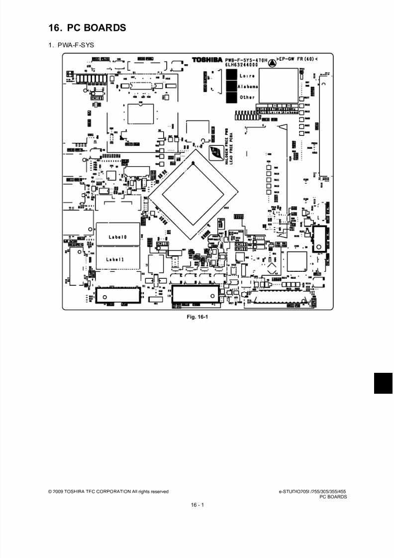
8/17/2019 Toshiba ES455 Service Manual
http://slidepdf.com/reader/full/toshiba-es455-service-manual 325/335
© 2009 TOSHIBA TEC CORPORATION All rights reserved e-STUDIO205L/255/305/355/455PC BOARDS
16 - 1
16. PC BOARDS
1. PWA-F-SYS
Fig. 16-1

8/17/2019 Toshiba ES455 Service Manual
http://slidepdf.com/reader/full/toshiba-es455-service-manual 326/335
e-STUDIO205L/255/305/355/455 © 2009 TOSHIBA TEC CORPORATION All rights reservedPC BOARDS
16 - 2
2. PWA-F-LGC
Fig. 16-2
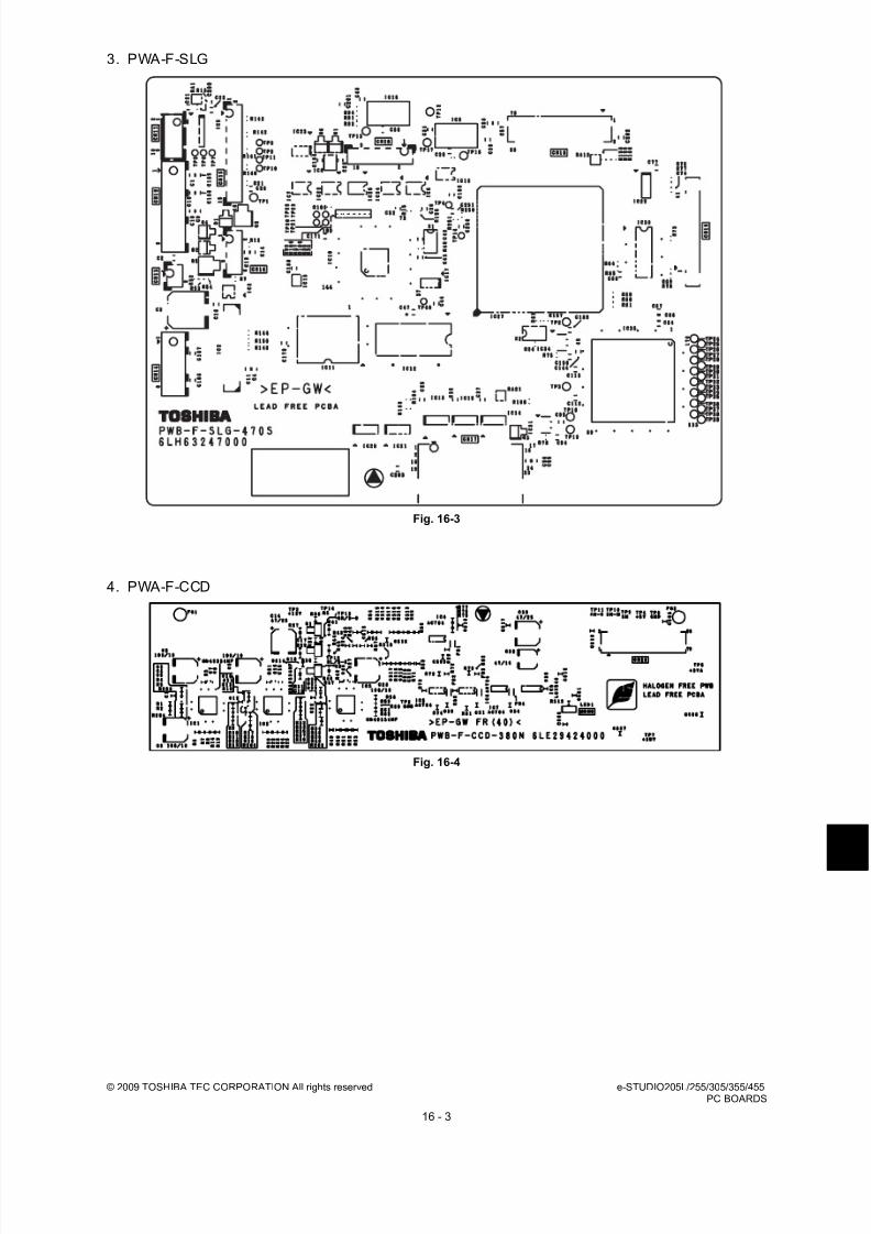
8/17/2019 Toshiba ES455 Service Manual
http://slidepdf.com/reader/full/toshiba-es455-service-manual 327/335
© 2009 TOSHIBA TEC CORPORATION All rights reserved e-STUDIO205L/255/305/355/455PC BOARDS
16 - 3
3. PWA-F-SLG
Fig. 16-3
4. PWA-F-CCD
Fig. 16-4
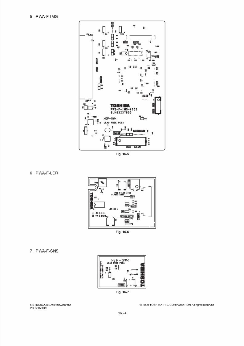
8/17/2019 Toshiba ES455 Service Manual
http://slidepdf.com/reader/full/toshiba-es455-service-manual 328/335
e-STUDIO205L/255/305/355/455 © 2009 TOSHIBA TEC CORPORATION All rights reservedPC BOARDS
16 - 4
5. PWA-F-IMG
Fig. 16-5
6. PWA-F-LDR
Fig. 16-6
7. PWA-F-SNS
Fig. 16-7

8/17/2019 Toshiba ES455 Service Manual
http://slidepdf.com/reader/full/toshiba-es455-service-manual 329/335
© 2009 TOSHIBA TEC CORPORATION All rights reserved e-STUDIO205L/255/305/355/455PC BOARDS
16 - 5
8. PWA-F-MOT
e-STUDIO205L/255/305
Fig. 16-8
9. PWA-F-MOT2
e-STUDIO355/455
Fig. 16-9

8/17/2019 Toshiba ES455 Service Manual
http://slidepdf.com/reader/full/toshiba-es455-service-manual 330/335
e-STUDIO205L/255/305/355/455 © 2009 TOSHIBA TEC CORPORATION All rights reservedPC BOARDS
16 - 6
10.PWA-F-DSP
Fig. 16-10
11.PWA-F-KEY
Fig. 16-11

8/17/2019 Toshiba ES455 Service Manual
http://slidepdf.com/reader/full/toshiba-es455-service-manual 331/335
© 2009 TOSHIBA TEC CORPORATION All rights reserved e-STUDIO205L/255/305/355/455PC BOARDS
16 - 7
12.PWA-F-FUS
* ASD/AUD/SAD/ASU/TWD/CND/IRD/ARD/KRD models: Standard, NAD/MJD models: Option
Fig. 16-12
13.PWA-F-CTRG
Fig. 16-13
14.PWA-F-EPU
Fig. 16-14

8/17/2019 Toshiba ES455 Service Manual
http://slidepdf.com/reader/full/toshiba-es455-service-manual 332/335
e-STUDIO205L/255/305/355/455 © 2009 TOSHIBA TEC CORPORATION All rights reservedPC BOARDS
16 - 8
8/17/2019 Toshiba ES455 Service Manual
http://slidepdf.com/reader/full/toshiba-es455-service-manual 333/335
© 2009 TOSHIBA TEC CORPORATION All rights reserved e-STUDIO205L/255/305/355/455REVISION RECORD
1
REVISION RECORD
Ver.01
Ver.01 <2009.06.03>
Page Contents
1-8 Errors in "1.2 Accessories" have been corrected.
1-10 An error in "1.4 Supplies" has been corrected.
2-22 Arrows have been added to Fig. 2-21.The direction of the antenna in Fig. 2-22 has been corrected.
2-27 A note for replacing the board has been added.

8/17/2019 Toshiba ES455 Service Manual
http://slidepdf.com/reader/full/toshiba-es455-service-manual 334/335
e-STUDIO205L/255/305/355/455 © 2009 TOSHIBA TEC CORPORATION All rights reservedREVISION RECORD
2

8/17/2019 Toshiba ES455 Service Manual
http://slidepdf.com/reader/full/toshiba-es455-service-manual 335/335