Embed Size (px)
Citation preview
Tough Enough for Today’s World
FIELD REPLACEABLE UNIT DOCUMENTATION
5200 Series
GENERAL INFORMATION
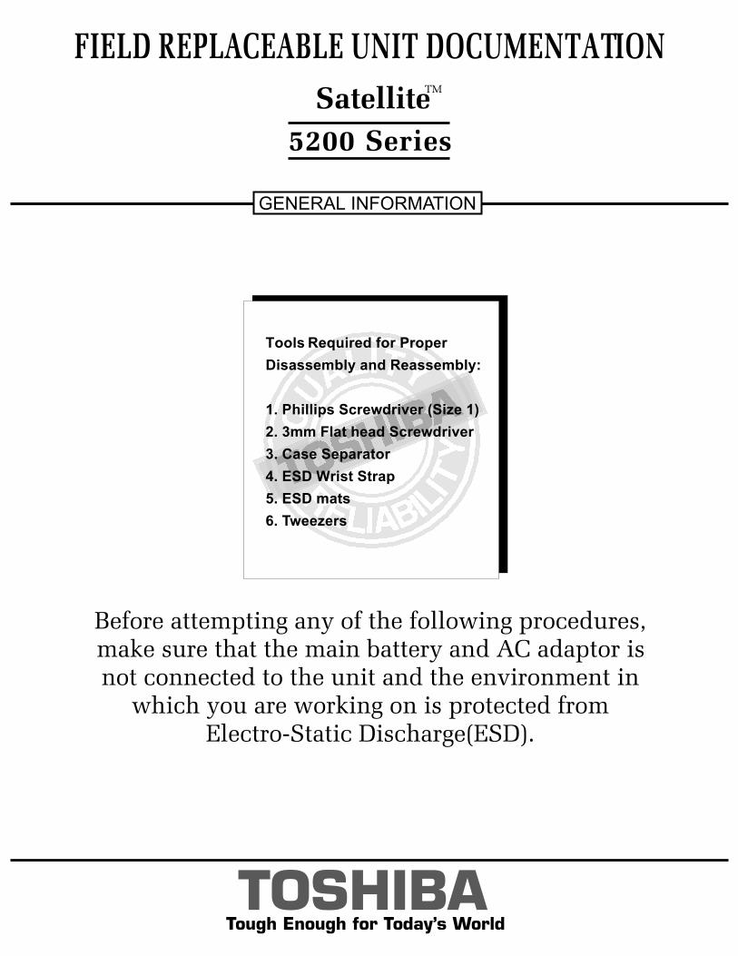
Before attempting any of the following procedures,make sure that the main battery and AC adaptor is not connected to the unit and the environment in
which you are working on is protected fromElectro-Static Discharge(ESD).
TOSHIBATough Enough for Today’s World
FIELD REPLACEABLE UNIT DOCUMENTATION
5200 Series
GENERAL INFORMATION
Before attempting any of the following procedures,make sure that the main battery and AC adaptor is not connected to the unit and the environment in
which you are working on is protected fromElectro-Static Discharge(ESD).
TOSHIBA
Tools Required for Proper
Disassembly and Reassembly:
1. Phillips Screwdriver (Size 1)
2. 3mm Flat head Screwdriver
3. Case Separator
4. ESD Wrist Strap
5. ESD mats
6. Tweezers
SatelliteTM
TOSHIBATough Enough for Today’s World
TABLE OF CONTENTS:
1. BATTERY PACK REMOVAL
2. OPTIONAL PC CARD REMOVAL
3. HDD REMOVAL
4. MEMORY MODULE REMOVAL
5. MINI PCI CARD REMOVAL
6. MODEM BOARD REMOVAL
7. KEYBOARD REMOVAL
8. TOP COVER REMOVAL
9. CD-R/W/DVD-ROM DRIVE REMOVAL
10. SPEAKER(WOOFER) REMOVAL
11. PC CARD SLOT REMOVAL
12. SOUND BOARD REMOVAL
13. RTC REMOVAL
14. COOLING MODULE REMOVAL
15. CPU REMOVAL
16. TOSHIBA STYLE BAY REMOVAL
17. USB BOARD REMOVAL
18. SYSTEM BOARD REMOVAL
19. SD CARD BOARD REMOVAL
20. CPAD AND SUB LCD REMOVAL
21. CD CONTROL/SUB LCD REMOVAL
22. SWITCH BOARD REMOVAL
23. SPEAKERS REMOVAL
24. 15’’ DISPLAY MASK REMOVAL
25. FL INVERTER AND 15’’ LCD REMOVAL
FIELD REPLACEABLE UNIT DOCUMENTATION
5200 Series Satellite
TM
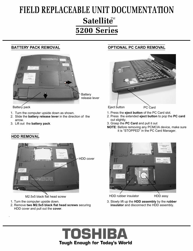
BATTERY PACK REMOVAL OPTIONAL PC CARD REMOVAL
TOSHIBATough Enough for Today’s World
1. Turn the computer upside down as shown.2. Slide the battery release lever in the direction of the arrow. 3. Lift out the battery pack.
1. Press the eject button of the PC Card slot.2. Press the extended eject button to pop the PC card out slightly.3. Grasp the PC Card and pull it out
HDD REMOVAL
3. Slowly lift up the HDD assembly by the rubber insulator and disconnect the HDD assembly.
1. Turn the computer upside down. 2. Remove two M2.5x5 black flat head screws securing HDD cover and pull out the cover.
.
NOTE: Before removing any PCMCIA device, make sure it is “STOPPED” in the PC Card Manager.
FIELD REPLACEABLE UNIT DOCUMENTATION
5200 Series Satellite
TM
Batteryrelease lever
Battery pack
M2.5x5 black flat head screw
HDD cover
HDD assyHDD rubber insulator
PC CardEject button
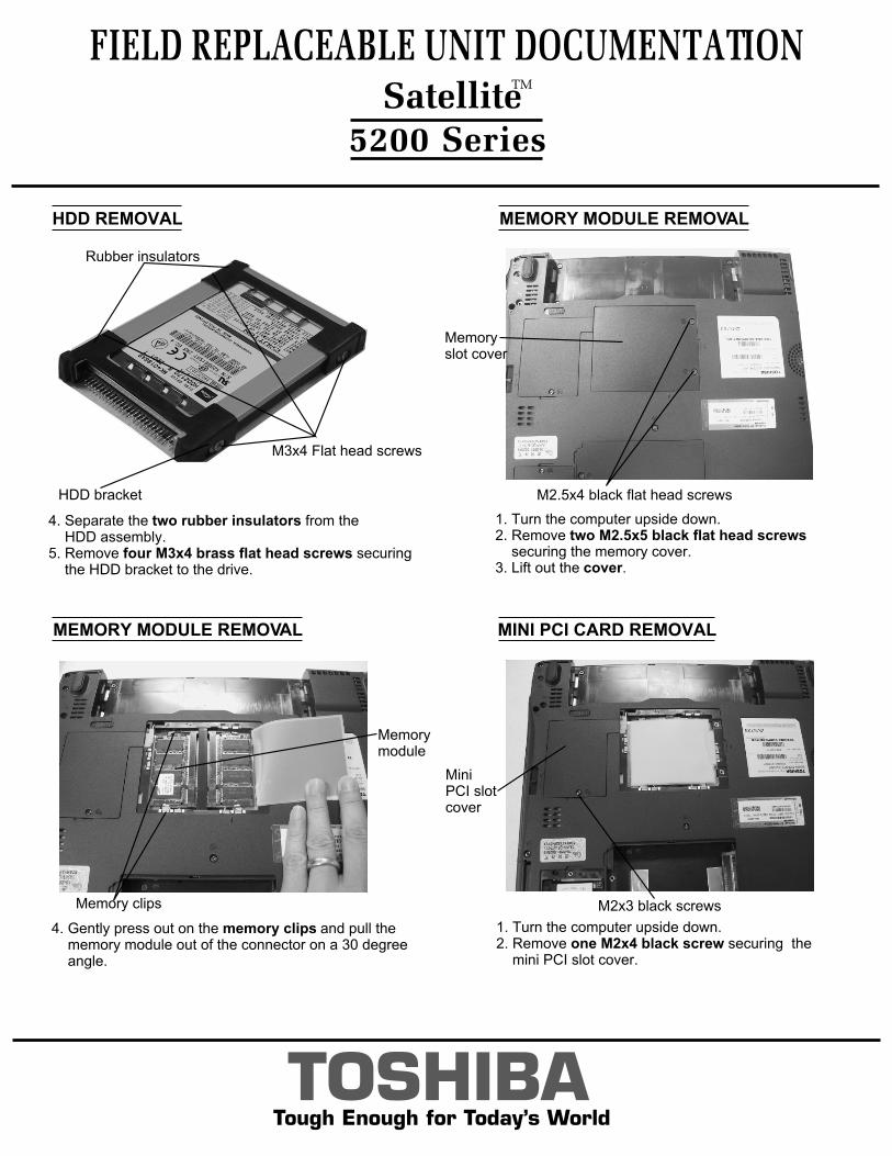
MEMORY MODULE REMOVAL
MEMORY MODULE REMOVAL
1. Turn the computer upside down. 2. Remove two M2.5x5 black flat head screws securing the memory cover.3. Lift out the cover.
TOSHIBATough Enough for Today’s World
MINI PCI CARD REMOVAL
FIELD REPLACEABLE UNIT DOCUMENTATION
5200 Series
HDD REMOVAL
4. Gently press out on the memory clips and pull the memory module out of the connector on a 30 degree angle.
SatelliteTM
1. Turn the computer upside down.2. Remove one M2x4 black screw securing the mini PCI slot cover.
M2.5x4 black flat head screws
Memoryslot cover
Memorymodule
Memory clips
Mini PCI slotcover
M2x3 black screws
4. Separate the two rubber insulators from the HDD assembly. 5. Remove four M3x4 brass flat head screws securing the HDD bracket to the drive.
M3x4 Flat head screws
HDD bracket
Rubber insulators
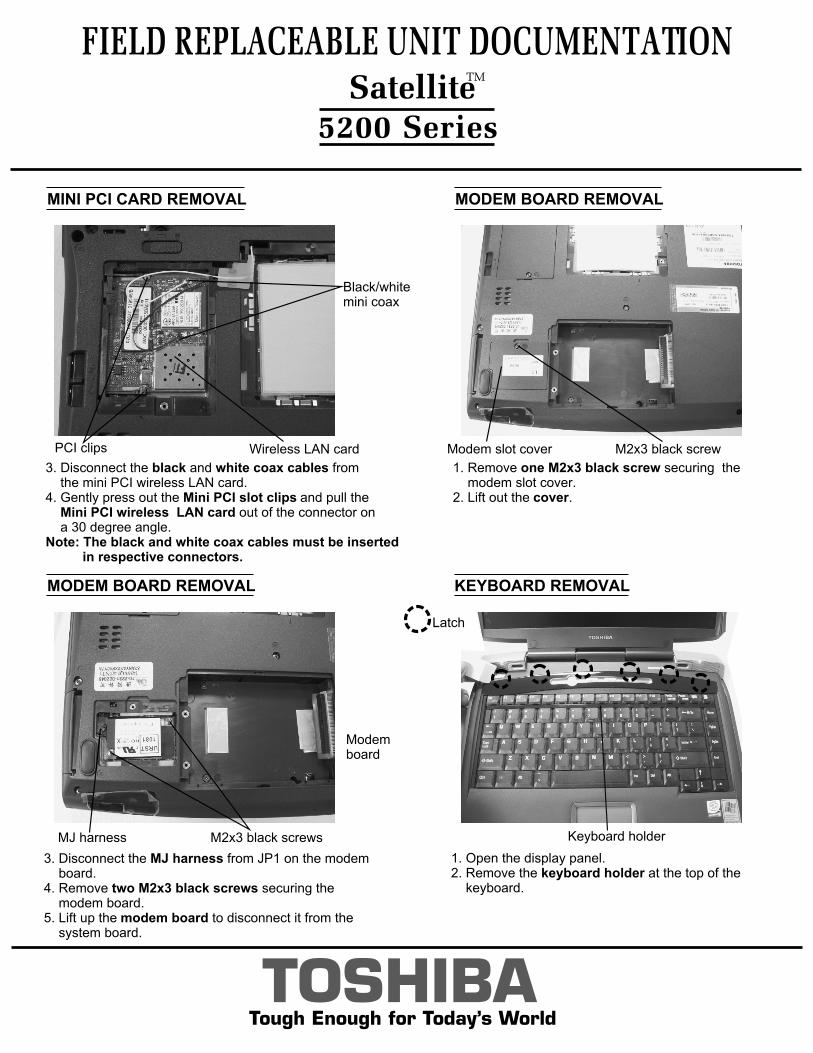
MODEM BOARD REMOVAL
MODEM BOARD REMOVAL
MINI PCI CARD REMOVAL
1. Remove one M2x3 black screw securing the modem slot cover.2. Lift out the cover.
TOSHIBATough Enough for Today’s World
1. Open the display panel.2. Remove the keyboard holder at the top of the keyboard.
KEYBOARD REMOVAL
FIELD REPLACEABLE UNIT DOCUMENTATION
5200 Series
3. Disconnect the black and white coax cables from the mini PCI wireless LAN card.4. Gently press out the Mini PCI slot clips and pull the Mini PCI wireless LAN card out of the connector on a 30 degree angle.Note: The black and white coax cables must be inserted in respective connectors.
3. Disconnect the MJ harness from JP1 on the modem board.4. Remove two M2x3 black screws securing the modem board.5. Lift up the modem board to disconnect it from the system board.
Keyboard holder
SatelliteTM
Latch
M2x3 black screwModem slot cover
MJ harness M2x3 black screws
Modem board
Wireless LAN cardPCI clips
Black/whitemini coax
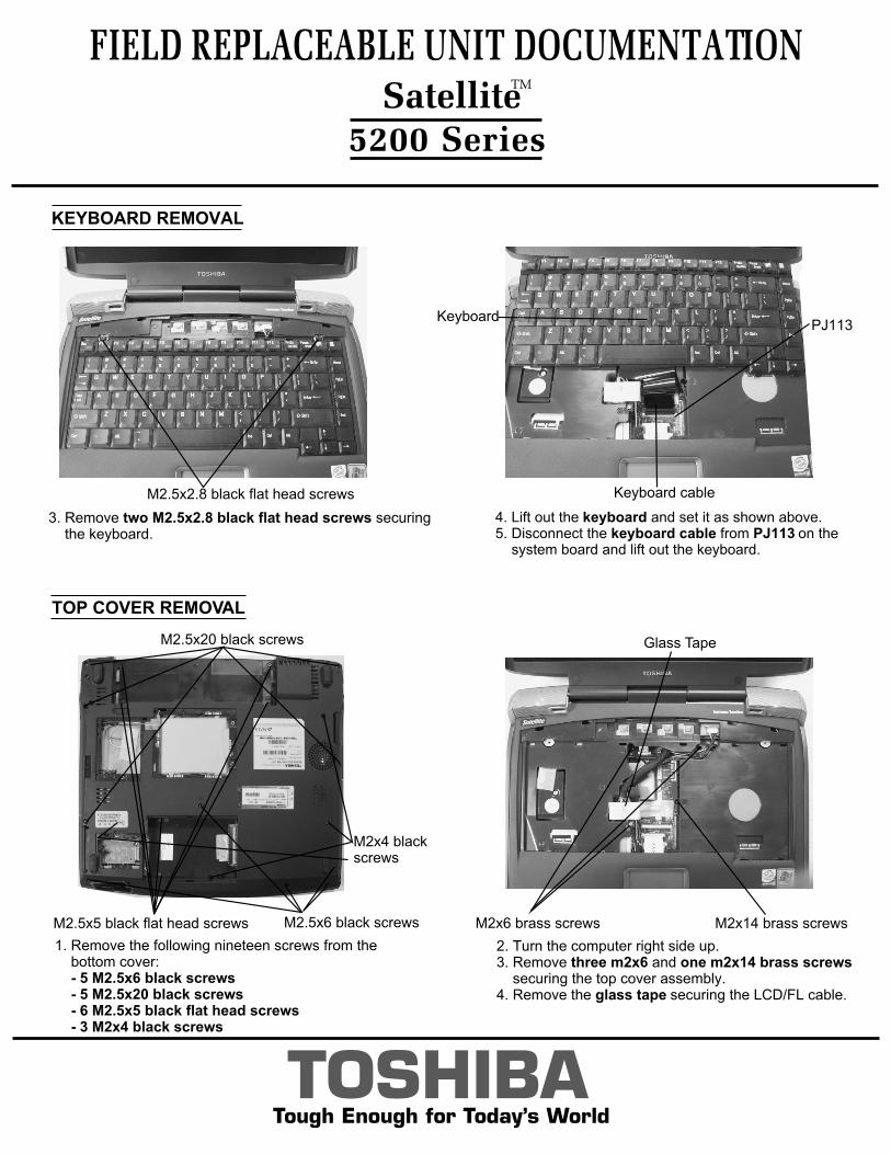
4. Lift out the keyboard and set it as shown above.5. Disconnect the keyboard cable from PJ113 on the system board and lift out the keyboard.
KEYBOARD REMOVAL
FIELD REPLACEABLE UNIT DOCUMENTATION
5200 Series
TOSHIBATough Enough for Today’s World
3. Remove two M2.5x2.8 black flat head screws securing the keyboard.
TOP COVER REMOVAL
SatelliteTM
1. Remove the following nineteen screws from the bottom cover: - 5 M2.5x6 black screws - 5 M2.5x20 black screws - 6 M2.5x5 black flat head screws - 3 M2x4 black screws
M2.5x2.8 black flat head screws
PJ113
Keyboard cable
Keyboard
M2.5x20 black screws
M2.5x5 black flat head screws M2.5x6 black screws
M2x4 blackscrews
2. Turn the computer right side up.3. Remove three m2x6 and one m2x14 brass screws securing the top cover assembly.4. Remove the glass tape securing the LCD/FL cable.
Glass Tape
M2x6 brass screws M2x14 brass screws
TOSHIBATough Enough for Today’s World
TOP COVER REMOVAL
FIELD REPLACEABLE UNIT DOCUMENTATION
5200 Series
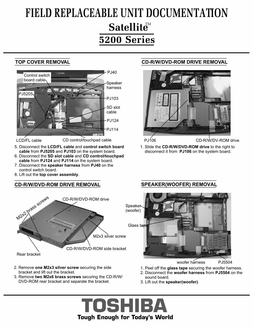
2. Remove one M2x3 silver screw securing the side bracket and lift out the bracket.3. Remove two M2x6 brass screws securing the CD-R/W/ DVD-ROM rear bracket and separate the bracket.
SatelliteTM
CD-R/W/DVD-ROM DRIVE REMOVAL
1. Slide the CD-R/W/DVD-ROM drive to the right to disconnect it from PJ106 on the system board.
5. Disconnect the LCD/FL cable and control switch board cable from PJ5205 and PJ103 on the system board.6. Disconnect the SD slot cable and CD control/touchpad cable from PJ124 and PJ114 on the system board.7. Disconnect the speaker harness from PJ40 on the control switch board.8. Lift out the top cover assembly.
PJ106 CD-R/W/DV-ROM driveLCD/FL cable
PJ5205
Speakerharness
PJ40
CD control/touchpad cable
PJ124
SD slotcable
PJ114
Control switch board cable
PJ103
M2x3 silver screw
CD-R/W/DVD-ROM side bracket
CD-R/W/DVD-ROM drive
M2x2 bra
ss sc
rews
Rear bracket
CD-R/W/DVD-ROM DRIVE REMOVAL SPEAKER(WOOFER) REMOVAL
1. Peel off the glass tape securing the woofer harness.2. Disconnect the woofer harness from PJ5504 on the sound board.3. Lift out the speaker(woofer).
woofer harness
Glass tape
Speaker(woofer)
PJ5504
TOSHIBATough Enough for Today’s World
PC CARD SLOT REMOVAL
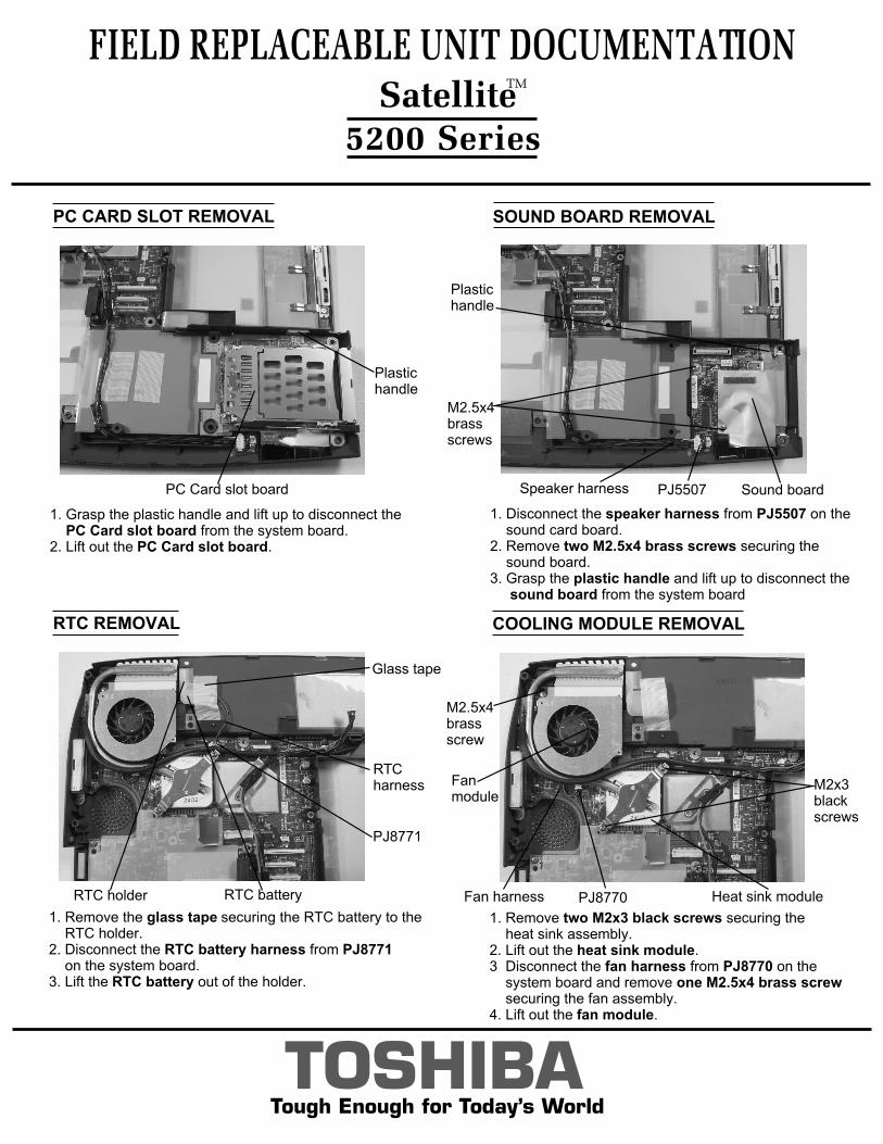
1. Grasp the plastic handle and lift up to disconnect the PC Card slot board from the system board. 2. Lift out the PC Card slot board.
FIELD REPLACEABLE UNIT DOCUMENTATION
5200 Series
RTC REMOVAL
1. Remove the glass tape securing the RTC battery to the RTC holder.2. Disconnect the RTC battery harness from PJ8771 on the system board.3. Lift the RTC battery out of the holder.
SatelliteTM
SOUND BOARD REMOVAL
1. Disconnect the speaker harness from PJ5507 on the sound card board.2. Remove two M2.5x4 brass screws securing the sound board.3. Grasp the plastic handle and lift up to disconnect the sound board from the system board
Plastic handle
PC Card slot board
M2.5x4brassscrews
Plastichandle
PJ5507Speaker harness Sound board
Glass tape
RTC harness
RTC batteryRTC holder
PJ8771
COOLING MODULE REMOVAL
1. Remove two M2x3 black screws securing the heat sink assembly. 2. Lift out the heat sink module.3 Disconnect the fan harness from PJ8770 on the system board and remove one M2.5x4 brass screw securing the fan assembly.4. Lift out the fan module.
Fan harness Heat sink module
M2x3black screws
PJ8770
Fan module
M2.5x4brassscrew
CPU REMOVAL
FIELD REPLACEABLE UNIT DOCUMENTATION
5200 Series
TOSHIBATough Enough for Today’s World
SatelliteTM
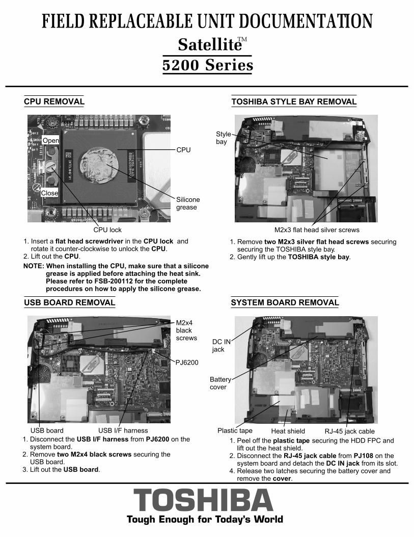
1. Insert a flat head screwdriver in the CPU lock and rotate it counter-clockwise to unlock the CPU.2. Lift out the CPU.
NOTE: When installing the CPU, make sure that a silicone grease is applied before attaching the heat sink. Please refer to FSB-200112 for the complete procedures on how to apply the silicone grease.
CPU
CPU lock
Silicone grease
Open
Close
TOSHIBA STYLE BAY REMOVAL
1. Remove two M2x3 silver flat head screws securing securing the TOSHIBA style bay.2. Gently lift up the TOSHIBA style bay.
USB BOARD REMOVAL
1. Disconnect the USB I/F harness from PJ6200 on the system board.2. Remove two M2x4 black screws securing the USB board.3. Lift out the USB board.
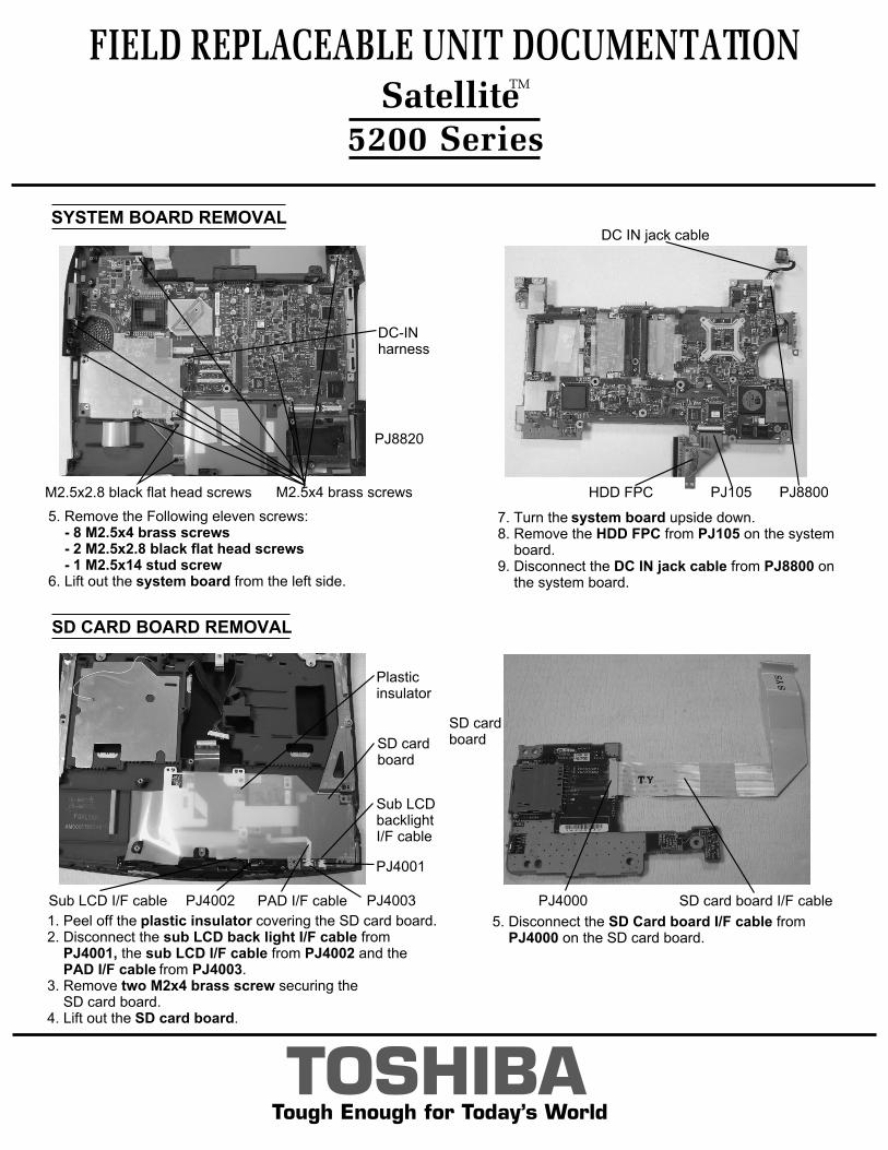
SYSTEM BOARD REMOVAL
1. Peel off the plastic tape securing the HDD FPC and lift out the heat shield. 2. Disconnect the RJ-45 jack cable from PJ108 on the system board and detach the DC IN jack from its slot. 4. Release two latches securing the battery cover and remove the cover.
M2x3 flat head silver screws
Style bay
M2x4blackscrews
USB I/F harnessUSB board
PJ6200
Plastic tape
Battery cover
RJ-45 jack cableHeat shield
DC INjack
TOSHIBATough Enough for Today’s World
FIELD REPLACEABLE UNIT DOCUMENTATION
5200 Series
SD CARD BOARD REMOVAL
7. Turn the system board upside down. 8. Remove the HDD FPC from PJ105 on the system board. 9. Disconnect the DC IN jack cable from PJ8800 on the system board.
1. Peel off the plastic insulator covering the SD card board.2. Disconnect the sub LCD back light I/F cable from PJ4001, the sub LCD I/F cable from PJ4002 and the PAD I/F cable from PJ4003. 3. Remove two M2x4 brass screw securing the SD card board.4. Lift out the SD card board.
SatelliteTM
SYSTEM BOARD REMOVAL
5. Remove the Following eleven screws: - 8 M2.5x4 brass screws - 2 M2.5x2.8 black flat head screws - 1 M2.5x14 stud screw6. Lift out the system board from the left side.
5. Disconnect the SD Card board I/F cable from PJ4000 on the SD card board.
DC-INharness
M2.5x2.8 black flat head screws
PJ8820
M2.5x4 brass screws PJ105HDD FPC PJ8800
DC IN jack cable
SD cardboard
SD card board I/F cablePJ4000
Plastic insulator
SD cardboard
Sub LCDbacklightI/F cable
PJ4001
Sub LCD I/F cable PJ4002 PAD I/F cable PJ4003
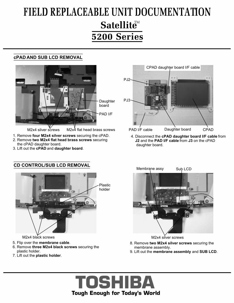
8. Remove two M2x4 silver screws securing the membrane assembly. 9. Lift out the membrane assembly and SUB LCD.
CD CONTROL/SUB LCD REMOVAL
5. Flip over the membrane cable.6. Remove three M2x4 black screws securing the plastic holder.7. Lift out the plastic holder.
FIELD REPLACEABLE UNIT DOCUMENTATION
5200 Series Satellite
TM
cPAD AND SUB LCD REMOVAL
1. Remove four M2x4 silver screws securing the cPAD.2. Remove two M2x4 flat head brass screws securing the cPAD daughter board. 3. Lift out the cPAD and daughter board.
TOSHIBATough Enough for Today’s World
M2x4 silver screws M2x4 flat head brass screws
Daughterboard
PAD I/F
CPAD daughter board I/F cable
CPADDaughter boardPAD I/F cable
PJ2
PJ3
4. Disconnect the cPAD daughter board I/F cable from J2 and the PAD I/F cable from J3 on the cPAD daughter board.
M2x4 black screws
Plastic holder
M2x4 silver screws
Sub LCDMembrane assy
FIELD REPLACEABLE UNIT DOCUMENTATION
5200 Series
TOSHIBATough Enough for Today’s World
SatelliteTM
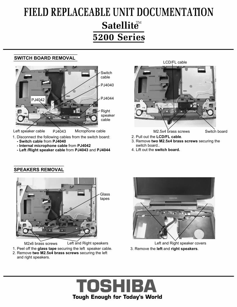
2. Pull out the LCD/FL cable. 3. Remove two M2.5x4 brass screws securing the switch board.. 4. Lift out the switch board.
1. Peel off the glass tape securing the left speaker cable. 2. Remove two M2.5x4 brass screws securing the left and right speakers.
3. Remove the left and right speakers.
SPEAKERS REMOVAL
Glasstapes
Left and Right speakersM2x6 brass screws Left and Right speaker covers
M2.5x4 brass screws
LCD/FL cable
Switch board
SWITCH BOARD REMOVAL
1. Disconnect the following cables from the switch board: - Switch cable from PJ4040 - Internal microphone cable from PJ4042 - Left /Right speaker cable from PJ4043 and PJ4044
Right speaker cable
Left speaker cable Microphone cable
Switch cable
PJ4040
PJ4042 PJ4044
PJ4043
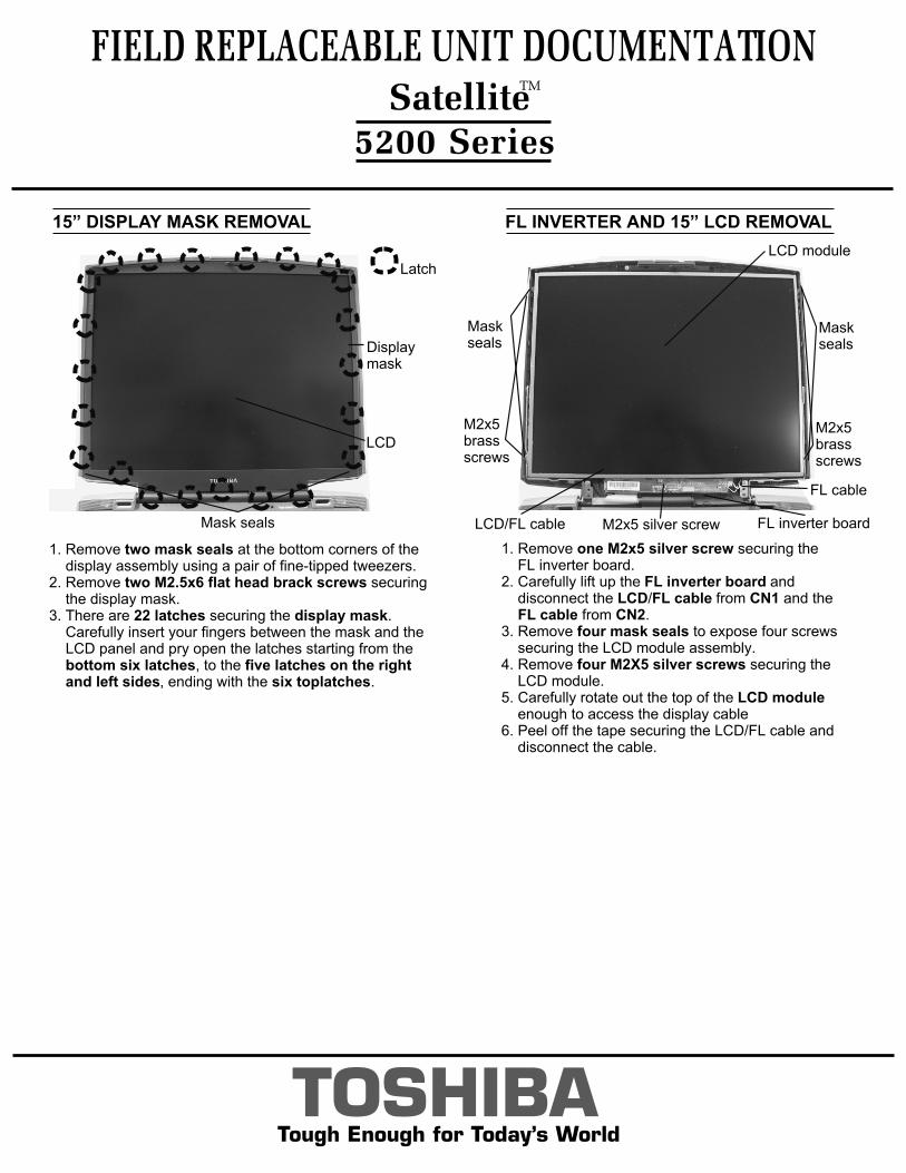
FL INVERTER AND 15” LCD REMOVAL
FIELD REPLACEABLE UNIT DOCUMENTATION Satellite
TM
5200 Series
TOSHIBATough Enough for Today’s World
15” DISPLAY MASK REMOVAL
1. Remove two mask seals at the bottom corners of the display assembly using a pair of fine-tipped tweezers.2. Remove two M2.5x6 flat head brack screws securing the display mask.3. There are 22 latches securing the display mask. Carefully insert your fingers between the mask and the LCD panel and pry open the latches starting from the bottom six latches, to the five latches on the right and left sides, ending with the six toplatches.
Latch
Mask seals
Displaymask
LCD
LCD module
M2x5 silver screw FL inverter board
M2x5brassscrews
M2x5 brassscrews
Maskseals
Maskseals
LCD/FL cable
FL cable
1. Remove one M2x5 silver screw securing the FL inverter board.2. Carefully lift up the FL inverter board and disconnect the LCD/FL cable from CN1 and the FL cable from CN2.3. Remove four mask seals to expose four screws securing the LCD module assembly.4. Remove four M2X5 silver screws securing the LCD module.5. Carefully rotate out the top of the LCD module enough to access the display cable6. Peel off the tape securing the LCD/FL cable and disconnect the cable.