Embed Size (px)
Citation preview

r- 1

To the audio professional, when a compressor or limiter is needed to tame the potentially disastrous consequences of uncontrolled level or to create special effects, one name stands out as the best: UREI.
Studio Standards for more than a decade, the compressors and limiters from UREI have earned their way into thousands of recording, mastering, and broadcast installa- tions around the world.
Because we built our reputation for unparalleled professional performance and quality with our compressors and limiters, we have continuously advanced their engineering and technology to offer more reliability, features and performance. When you need the fastest, quietest and most flexible gain control instruments available, you can be totally assured that these products will prove to you why they've earned the title - Studio Standard:
The Model LA-4 A single channel, half -rack unit with patented electro- optical attenuator. Featuring smooth, natural sounding MIS action, it offers selectable compression ratios, a large VU meter, adjustable output and thresh- old levels and stereo coupling. The Model 1176LN A peak limiter which features adjustable input and output levels; individual attack and release time controls; selectable compression '
ratios; switchable metering; and
stereo coupling. The 1176LN is the most widely used limiter in the world. The Model 1178 A two channel version the The UREI v of 1176LN in a compact (3 -1/2) rack Compressor /Limiters mounting design. Featuring perfect tracking in the selectable stereo mode, it additionally offers selectable VU or Peak reading meter ballistics.
From One Pro To Another - trust all your toughest signal processing needs to UREI.
CHANNEL 8
CI From One Pro To Another United Recording Electronics Industries 8460 San Fernando Road. Sun Valley. California 91352 (213) 767 -1000 Telex: 65 -1389 UREI SNVY Worldwide: Gotham Export Corporation. New York; Canada: E.S. Gould Marketing. Montreal
See your professional audio products dealer for full technical information.

Publisher Larry Zide
Editor John M. Woram
European Editor John Borwick
Associate Editor Mark B. Waldstein
Advertising Production & Layout Karen Cohn
Classified Advertising Carol Vitelli
Book Sales Lydia Calogrides
Circulation Manager Eloise Beach
Art Director Bob Laurie
Graphics K & S Graphics
Typography Spartan Phototype Co.
sales offices Roy McDonald Associates, Inc.
Dallas, Texas 75237 First Continental Bank Bldg.
5801 Marvin D. Love Freeway Suite 303
(214) 941 -4461
Denver, Colorado Area Englewood, Colorado 80112
14 Inverness Dr. East Bldg. 1- Penthouse
(303) 771-8181 Houston, Texas 77036 6901 Corporate Drive
Suite 210 (713) 988-5005
Los Angeles Area Glendale, California 91204 424 West Colorado Street
Suite 201 (213) 244-8176 Portland Area
Hillsboro, Oregon 97123 510 South First
P.O. Box 696 (503) 640-2011
San Francisco Area Emeryville, California 94608 265 Baybridge Office Plaza
5801 Christie Avenue (415) 653-2122
Sagamore Publishing Co., Inc. New York
Plainview, NY 11803 1120 Old Country Rd.
(516) 433 -6530
About The Cover High in the Andes mountains near
Quito, Ecuador, the antennae of HC'JB radio transmit "l.a Voi de los Andes" to the rest of the world. In editor John Woram's cover photo, we catch a glimpse of an antenna designed by Clarence Moore. who later founded Crown International.
DEPARTMENTS
LETTERS 6
APRIL 1982 VOLUME 16. NO. 4
CALEN DAR 8
EDITORIAL 34
CLASSIFIED 66
DIGITAL AUDIO Barry Blesser 10
THEORY AND PRACTICE Ken Pohlmann 16
SOUND WITH IMAGES Len Feldman 24
SOUND REINFORCEMENT John Eargle 28
NEW PRODUCTS AND SERVICES 62
l'EOPLE, PLACES, HAPPENINGS 68
FEATURES
A db SPECIAL REPORT: BROADCAST MANUFACTURERS SURVEY 39
Mark B. Waldstein
BROADCASTING AND RECORDING IN ECUADOR 44
John M. Woram
SELECTIVE LIMITING Nigel Branwell 52
BROADCAST AUDIO A PRIMER FOR THE RECORDING ENGINEER 54
Garry Margolis
db. the Sound Engineering Magarine ( ISSN WI I -71451 is published monthly by Sagamore Publishing Company. Inc. I mue coo- tents eopyright ` 1982 by Sagamore Publishing ( -o., 11 2001d Country Road. Plains rew. l_i.. N.Y. 1 1801. Ielephone1516i 433 6530. db u published Ior those Indr.tduais and lams in prolcsmmnai audio- recording. broadcast. audio -visual -sound reinforcement. con- sultants. video recording. lüm sound. etc. Application should he made on the subscription form in the rear of each issue Subscrip- tions arc $15.00 per year (528.00 per year outside U.S. Possessions; 516.00 per year Canada) in U.S. funds. Single copies arc 51.95 each. Editorial. Publishing and Sales 0l1 lces: 1120 Old Country Road. Plains lev.. New York 11803. Controlled circular nn postage paid al Plainview. NY 1 1803 and an additional mailing office. (71

Bi-v.t :._.s
..-'SAOS SUPPLIED
PLACE YOUR ORDER TODAY
O C.
THD-1
L EAS'JVE LI ALS AS WELL IS
.R A+ON>LIr:EC SIGNALS
'iv0111105 c.
COARSE rRE,OEVCY
n1. .n rvICT:OI SWITCr.
.,.50 snipping S nari'-
PAG -1 PORTABLE MelO GENERATOR
GTNERATES TRE COMPLETE 411310 SPECTIIP TOR ruts TESTON:.
LOW DISTORTION
II -CLICS :ONTMNS TOR EASY
RESEITI56.
GREAT FOR SETTING LEVELS A
TASTING YES>OISE , A SYSTE,
$129.95 .03.50 shipping 5 handling
Ö O
USE 17UP VISA OP YAS.TCP ,f,APL.
;- o D
AVM -1 AC VOLTMETER
$79.95 i aping a handling
AFM-1 AGOTO FREQUENCY METER
MASQUES AYAL050E 'YEOOP:::II IN ME RAISE Or 0_lOW SST
REQUIRES NO TUO. )R MIA AnJOSnEITS.
5 A.,,MAC.
., .Wer)SI:r .Va. ..a,
$79.95 .53.50 shipping & Handling
o
Ö 30
SEND FOR YOUR FREE COPY OF OUR
NEW EXPANDED 1982 CATALOG
éáné SESCOM. INC. RETAIL SALES DIVISION I l l I Las Vegas Blvd. North L Vegas. NV 89101 -1197 U.S.A.
(702)384 -0993 (800)634 -3457
TWX (910)397 -8996
Circle 19 on Reader Servire Card
Index of Left Pit Aldver tlsen
EXTRA "M" MAKES A DIFFERENCE
To THE EDITOR: In his otherwise interesting and useful
article. "Monitoring Program Levels." in the December 1981 db Magazine. Jack K. Gordon includes a misstatement:
The test tone reference -level for a
reading of zero VU is +4 dBm..." I'm sure what Mr. Gordon meant to
say was: "The test tone reference level of +4 dBm drives the pointer on a VI meter to an apparent readingofzero V U."
Of course, the actual level is +4 VU because the attenuator setting of +4 must be added to the apparent meter reading to obtain the actual VU value. ANSI C16.5 -1954 stipulates that a standard volume indicator (VI) consists of two parts -(I) a meter and (2) an attenuator or pad. Because current VI meters do not include an attenuator (hence do not truly meet the standard). their manu- facturers have adjusted their sensitivity so that 1.23 volts drives the pointer to an apparent reading of zero VU. This is
done so that one of the new meters minus an attenuator will have its pointer at the same position on the meter scale as the older meters with their attenuator when both are driven with the same signal. It is.
necessary. however. to add +4 to the new meter reading to obtain the correct level.
A very interesting reference explain- ing all of this in greater detail is: "What the VU Meter Is Is Not/ Will Be" by Dr. Ronald Gubisch of Weston Instru- ments in the October 1977 issue of BM E
magazine. pp. 82 -86. To summarize: a correctly calibrated
VI meter will read a total value (pointer value plus any attenuator values present) of zero VU when the test signal is a con- tinuous sine wave .775 volts RMS into a
600 ohm load (1 milliwatt) and when the VI meter is bridged across the 600 5z
load. DON DAVIS. President Synergetic Audio Concepts
To THE EDITOR: I was thoroughly puzzled by Mr. Davis'
observation until I noted that an extra "m" had crept into my FIGURE I. so that the vertical scale for the general unread - peak curve of the VU Meter had become absolute. Hence Mr. Davis' inference that meter calibration was being dis- cussed. and his valid comments on that subject. But substitute "dB" (relative) for "dBm" (absolute) on the vertical scale.
(Continued un page hll)
American Song Festival 31
Ampex Cover III. 57 Aspen Music Festival 12
Auditronics Cover 1V Beyer 23
Cetec Vega 18
Electro -Voice 29 Fitzco 10
Garner 20 Hewlett- Packard 61
JBL 9
Kimball 8
Klark -Teknik 21
Lexicon 27 Linear & Digital Systems. Inc 22 Magnefax 63 Maxell 13
MCI 35 -38 Otari 58 -59 Panasonic 15
Polyline 22
Saki Magnetics 14
Sescom 6
Shure Bros. 7
Sound Technology 17
Standard Tape Labs 53 Swintek 26 3M 25. 43. 45. 47. 49 Telex 16
TOA 11. 19
LREI Cover II White 8
Coming Next Month
May's topic is recording studios. Howard Sherman checks in with a report on Normandy Sound in Providence. Rhode Island: our own Ken Pohlmann gives us a look at what's new at Criteria Studios in Miami. and Bill Kothen provides us with the details on Select Sound Studio. Buffalo's only 24 track studio. In addition. Curtis Chan takes a
detailed look at the Sony PC M -3324 digital tape recorder. and our European correspondent John Borwick reports on the recently -concluded AES conven- tion in Montreux. All this and more in
May's db -The Sound Engineering Magazine.
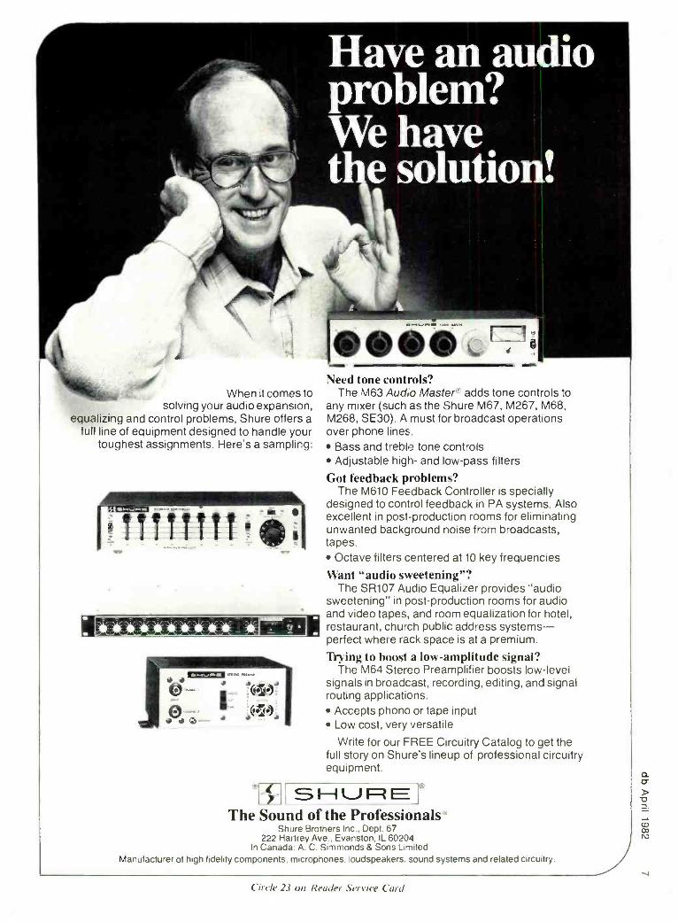
When it comes to solving your audio expansion,
equalizing and control problems, Shure offers a full line of equipment designed to handle your
toughest assignments. Here's a sampling:
Need tone controls? The M63 Audo Master' adds tone controls to
any mixer (such as the Shure M67. M267, M68, M268, SE30). A must for broadcast operations over phone lines.
Bass and treble tone controls Adjustable high- and low -pass filters
Got feedback problems? The M610 Feedback Controller is specially
designed to control feedback in PA systems. Also excellent in post -production rooms for eliminating unwanted background noise from broadcasts, tapes.
Octave filters centered at 10 key frequencies
Want "audio sweetening "? The SR107 Audio Equalizer provides "audio
sweetening" in post -production rooms for audio and video tapes, and room equalization for hotel, restaurant, church public address systems - perfect where rack space is at a premium.
'Frying to boost a low- amplitude signal? The M64 Stereo Preamplifier boosts low -level
signals in broadcast, recording, editing, and signal routing applications.
Accepts phono or tape input Low cost, very versatile
Write for our FREE Circuitry Catalog to get the full story on Shure's lineup of professional circuitry equipment.
SHURE 0
The Sound of the Professionals Shure Brothers Inc.. Dept. 67
222 Hartrey Ave., Evanston, IL 60204 In Canada: A. C. Simmonds & Sons Limited
Manufacturer of high fidelity components. microphones. loudspeakers. sound systems and related circuitry.
Circle 23 on Reader Service Card

co rn
a
THE EXPANDABLE SYSTEM 200
/ Broadband Memory Control Di splay and I Input /Out Resolution Fitters T. and Options
Advanced Microprocessor Controlled Real Time Analyzer. Featuring:
Interchangeable Filters 45 dB Dynamic Range 16 x 31 High Intensity LED Display 8 Non -volatile Memories
All Functions Microprocessor Controlled. Plug -in Options Available
3 Smoothing Time Constants Simultaneous Peak and Average Processing 0.5 dB Precision T0 Measurements
3 dB, 2 dB or 1 dB Resolution Bpilt-in Pink Noise Generator 15 V Microphone Power Oscilloscope and Plotter Drive Optional Function Generator
:
, ,: nium li nli- i11111I11n11L1I1ii11nIi111iF
\Oak Ira st rt.41114a rits. ¡rum. P. O. Box 698, Austin, Texas 78767 512. 892 -0752 TELEX 776409 WHITE INST AUS
More and more recording studios are discovering the great sound of the Kimball Professional Grand. Here's why: The Kimball 6' 7" Professional Grand derives its heri-
tage of greatness from the world's finest piano -the Bosendorfer. The scale and plate design are derived from the Bosendorfer Model 200, and the plate is ex- tra thick to assure maximum sustain and to avoid plate noise from hammer strikes. The Bosendorfer-derived scale and non - duplexed trebles enhance tonal depth, clarity, and pitch perception. The Kimball Professional Grand is specifically designed for clear, pure tonality, free of spurious noise and false harmonics. It also offers superior durability and tuning stability. Its entire struc- ture, including the soundboard, is of precision -laminated woods, greatly reducing eifferential expansion in changes of temperature and humidity.
kim8a1T The key resounding great' 349 Royal St. Box 460
tasper,:IN 47546
far more information about the Kimball
Professional Grand, contact Wade Bray at (812) 482 -1600.
Circle 35 on Reader .Servire Curd
Calendar APRIL
24 Midwest Acoustic Conference. Hermann Hall, Illinois Institute of Technology Chicago, IL. For more information contact: Hugh Pearl, Shure Bros., Inc., 1501 W. Shure Drive, Arlington Heights, IL. Tel: (312) 259 -7700, ext. 313.
29 -30 Electronic Distribution Show and May Conference. New Orleans Hilton,
I LA. For more information con- tact: David L. Fisher, Executive Vice President Electronic Indus- try Show Corporation, 222 South Riverside Plaza, Suite 1606, Chi- cago. IL 60606. Tel: (312) 648- 1140.
29 -30 3rd National Sound and Elec- May Ironic Systems Conference. New
I Orleans Marriott Hotel, New Or- leans. LA. For more information contact: National Sound and Com- munications Association. 5105 lollview Dr.. Rolling Meadows. IL 60008. Tel: (312) 577 -8360.
30 National Council of Acoustical May Consultants (N('AC) 20th Anni-
versar Meeting. Indian Lakes Resort. Bloomingdale. Illinois. For more information contact: NCAC. 66 Morris Ave.. 1'.O. Box 359. Springfield. NJ 07081. Tel: (20I) 379 -1100.
MAY
4 -6. Syn -Aud -Con Seminars. 4 -6. San 12 -14. Francisco: 12 -14. Salt Lake City: 25 -27 25 -27. Minneapolis. For more in-
formation contact: Syn- Aud -Con. P.O. Box 669. San Juan Capi- strano. C:\ 92693. Tel: (714) 496- 9599.
JUNE 4 -6 AES Conference: 11w New Vsorld
of Digital Audio, R e limn Hil- ton. Rye. NY. For more informa- tion contact: AES Headquarters. 60 E. 42nd St.. New York. NY 10165. Tel: (212) 661 -8528.
10 -13, National Video Festival. Spon- 24-27 sored by American Film Institute
and Sony. June 10 -13, Kennedy Center. Washington. D.C.. June 24 -27. AH Campus. Hollywood. CA. For more information con- tact: Television and Video Ser- vices program of the American Film Institute. Kennedy Center. Washington, D.C. 20566.
21- MIT's Experimental Studio Sum - luly mer Session. Cambridge. MA. 30 June 21 -July 2. Techniques of
Computer Sound Synthesis: July 5 -30. Workshop in Computer Music Composition. For more in- formation contact: Director of the Summer Session. Room E19- 356. Massachusetts Institute of I echnology. Cambridge. \1A 02139.

Before you invest in new studio monitors, consider all the ankles.
\o one has tu tell you how impor- tant flat frequency response is in a
studio monitor. But if you judge a
monitor's performance by its on -axis response curve, youire only getting part of the story.
Most conventional monitors tend to narrow their dispersion as frequency increases. So while their on -axis response may be flat, their off -axis response can roll off dramatically, liter - ally locking you into the on- axis "sweet spot:' Even worse, drastic changes in the horns directivity contribute signif- icantly to horn colorations.
Introducing the JBI. Bi- Radial Studio Monitors.
At JBI.. \te'ye been investigating the relationship bet%yeen on and off axis frequency response for several years. The result is a new generation of studio monitors that provide flat response over an exceptionally wide range of horizontal and vertical angles. The sweet spot and its traditional restrictions are essentially eliminated.
The key to this improved perfor- mance lies in the unique geometry of the monitors Bi- Radial horn) 1)e.el- oped with the aid of the latest com- puter design and analysis techniques, the horn provides constant coverage from its crossover point of 100(1 Hz to beyond lo kHz. The Bi- Radial compound flare configuration main- tains precise control of the horn's %vide 100° x 100° coverage angle.
I. Patent applied for.
JBL Professional Products Division
7ipira/ horizonta/
T tie c/ culled//
And the Bi- Radial horn's perfor- mance advantages aren't limited to just heamwidth control. The horn's rapid flare rate, for instance, dramatically reduces second harmonic distortion and its shallow depth allows for opti- mal acoustic alignment of the drivers. This alignment lets the monitors fall well below the Blauert and Laws criteria for minimum audible time delay discrepancies.
But while the Bi- Radial horn offers outstanding performance. it's only part of the total package. The new monitors also incorporate JBLs most advanced high and low fre- quency transducers and dividing networks. Working together. these
Polar response comparison ofa typical two- way coaxial studio monitor and JRI.} new 4130 Br- Radial studio monitor from J kHz to JO kHz.
.11il, !LlOhr,rr:r,utrd
JR], !/.l0 vertical
components provide exceptionally smooth response, high power capa- city, extended bandwidth. and extremely low distortion.
Judge For Yourself Of course. the only way to really
judge a studio monitor is to listen for yourself. So before you invest in new monitors, ask your local J BL profes- sional products dealer for Bi- Radial monitor demonstration. And consider all the angles.
James 13. Lansing Sound, Inc. 8500 Balboa Boulevard P.O. Box 220(1 Northridge. California 91329 U.S.A.
Circle 33 on Reader Service Card
7lt. /Nu man mternatami
Avanane in Canada through Gou/d Marketing Montreal Quebec co

/ o
P-260:0 D, INC.
AAE "Concept One" Automation
AKG
AMPEX
AMPEX TAPE
AUDIOARTS ENGINEERING
BGW TANNOY
HANNAY
(Cable Reels)
EVENTIDE
WIE
LEXICON
SENNHEISER
TECHNICS
VEGA
WIREWORKS
204 N. Midkiff Midland, Texas 79701
(915) 684 -0861
Circle 13 an Reader Servire Card
BARRY BLESSER
Digital Audio
High Level
Architecture
Last month we discussed the details of building a digital delay line using shift registers, which in turn were made out of flip- flops. For a short delay, this requires relatively few discrete flip -flops. A fixed longer delay could be made with shift - register ICs. However, these approaches have certain disadvantages, so let's con- sider a new approach to achieving a specified functionality.
RING MEMORY FIGURE I represents a "ring" of mem-
ory cells with no interconnections. Think of the ring as being made up of N indi- vidual flip -flops. numbered from() to N -1
(for our discussion, let's assume there are 4,096 flip -flops for N). In order to pass data from our input to a specific flip -flop. we first need a 12 -bit number to tell us the "address" of the flip -flop which is to receive the data.
Conceptually, think of each memory cell as being made up of the circuit shown in FIGRI 2. This flip -flop has a special comparator which compares two digital numbers, each of 12 bits. When the numbers are the same, it puts out a clock; otherwise, it does nothing. Each of the cells has its own 12 -bit code number. For example. cell 7 has code number 000.000 .000.I II. and cell 4.094 would have code number 1 11,1 11.1 11.1 I0. This
I_ -hit code number
Code number 1 1 1 1 1 1 1 1 1 I 1 1
for cell 3357- I 1 0 1 0 0 0 1 1 1 0 1
Con parator
-- Figure 1. A ring of memory cells.
makes each cell unique. and only one cell's number will match any given address (the address is the other 12 -bit number which is sent to the comparator.
Now we are ready to connect up our ring memory. All of the D inputs are wired in common to form a master D input for the full ring; all of the address wires are also wired in common. We need a total of 14 wires for the entire memory: one input wire. 12 address wires. and one output wire (not yet mentioned). Since we also need power and ground, the total number of pins is 16. which is easy to put on one IC chip. This kind of access to a memory is called address decoding. All of the flip -flop inputs and outputs are wired together, but a separate data word is used to select which one is actually being considered.
The next step in our development is to introduce the concept ofa pointer. This is
a convenient way of identifying which cell is being addressed. Moreover, we can discriminate between a READ pointer and a WRl I t: pointer, as shown in FIGURE 3.
The input pointer is at memory cell 13. and the output pointer is at memory cell 7.
In other words. we are writing data into cell 13, and reading data from cell 7. Next, both pointers are advanced by one count. The input pointer would now write the next data into cell 14 while the
IIIIIIIIIIII. 1_- it address hts
L
4095 other Flip -Flops
Cell 3357
IIII'I1(IP
Figure
Output
Figure 2. Circuit of a memory cell.

THE RUGGED, COMPACT TOA MONITORS DESIGNED TO PERFORM WHERE YOU NEED THEM THE MOST.
For the stage, the powerful SM -60 stage monitor speaker system. For the studio or stage, the equally powerful RS -21M reference mini -monitor. Both as small and as rugged as we could en- gineer them- without compromising the performance you need for accuracy and higher power- handling. They're everything you've always wanted in smaller, high quality monitors. And less. Less bulk and less set -up hassles.
Our SM -60 is a full- range, dual trans- ducer speaker system with a rated in- put of 70 watts? It features a sensitivity of 90 dB SPL -for operation at levels that really cut through. The frequency response is 110Hz to 16kHz- extended top and bottom to cover a broad musical range. And instead of cheap plastic or flimsy wooden boxes, we enclose the SM -60 in a tough, extruded aluminum shell with solid cast end panels.
When you make your set -ups with an SM -60 you've got options too. The ad- justable mounting bracket will securely attach the monitor to the top of the mic stand or anywhere along the stand itself. And when a speaker cable is stepped on, you're not going to lose the show because the connections are terminated with our exclusive positive -locking, 1/4"
phone jack. The RS -21M is a closed enclosure,
full -range reference monitor that can handle a rated input of 35 watts" It gives you a sensitivity of 88 dB SPL (1W @lm) and a frequency response of 100Hz to 17kHz. The RS -21M is de- signed to fit right where you usually need it the most -right on top of the meter bridge of our RX Series boards.
Both new monitors can take the tough- est, continuous high power use on stage or in studio. They're companion
systems that join our compact RX Series consoles and the extension of our philosophy that professional sound gear doesn't have to be bulky, unsightly and a drag to set -up.
The SM -60, the RS -21M and our RX Series consoles- they're big on perfor- mance and stingy on space, the kind of studio equipment designed to perform where you need it the most. 16 ohms "8 ohms
Crafted in Japan Proven in the States.
TOA Electronics, Inc. 480 Carlton Court South San Francisco, Ca. 94080 (415) 588-2538 Telex: 331 -332
In Canada: TOA Electronics, Inc. 10712 -181 Street Edmonton, Alberta T5S 1E8 (403) 489 -5511 Telex: 037 -43255

Output
Read
pointer
\ \..- \ ......__..... ../ \\
Figure 3. Pointer representation of ring memory.
outward pointer reads data from cell 8. With each advance of the pointers, the output data will be the same as the input data, but delayed by 6 counts. Since the "pointer" is actually a I2 -bit data word which increments by one unit every cycle, this could be implemented by a counter.
IMPLEMENTATION We can now see the way in which the
ring memory must be implemented. Apparently, there need to be two pointers which increment once per clock cycle.
These pointers (address words) need to differ by a fixed amount (delay value). FIGURE 4 shows a simple implementa- tion, which eliminates the complexity of requiring two pointers for the address decode of the ring memory. This would require two address decodes: one for the input, and one for the output. In- stead, we have made the address selection of the cell the same for input and output; but we now need an extra select input to determine if the operation is to be read (output) or write (input).
FIGURE 4 shows the way in which the read and write cycles can share the same hardware using the concept of time multiplexing. (For diagram simplicity. signals which are bits in a word are represented collectively as a single line, but with a number giving the true number of wires.) The counter is a 12 -bit counter
Counter
Adder
Delay number
with 12 output signals going to the 12
input pins of the adder. The delay number to be added comes from a binary switch (conceptually) which allows the user to select the offset between the two pointers. A digital switch. called a
multiplexer, allows a Select Bit to deter- mine which way the switch is thrown. Thus, the actual I2 -bit address data presented to the ring memory is either the counter (input pointer) direct or the counter -plus- offset (output pointer). The Select Bit will also determine if the ring memory is to read data or write data.
This is a flexible memory because its basic characteristics can be changed by changing the offset factor. It is even more flexible because we could add additional pointers in order to create additional delay lines. Since a point can actually be used for both operations, an additional
RI 4Up (N'HIIF
t' 1
Ring memory
/I
Figure 4. Read and write cycles sharing the same hardware via time multiplexing.
GORDON HARDY President & Dean JORGE MESTER Music Director
announce
AUDIO -RECORDING INSTITUTE HAROLD BOXER - Director
Three three -week sessions offering experience in recording live symphony, opera, and chamber music with world- renowned artists.
June 21- August 22, 1982 Aspen, Colorado
"The Aspen Audio -Recording Institute has something no other recording studio -oriented course has -the Aspen Music Festival."
BILLBOARD MAGAZINE
Address all inquiries to: Aspen Music Festival, 1860 Broadway, New York, NY 10023 (212) 581 -2196 After June 1st: Box AA, Aspen, Colorado
81612 (303) 925-3254
The Aspen Music School admits students of any race, color, and national or ethnic origin.
(' irrte 24 on Reader Service Card
Input (read dala)
Output (write data)
Select hit tread /write)
pointer gives a new line; i.e. 3 pointers gives 2 lines. as shown in FIGURE 5.
The pointer represented by Output I
Input 2 means that when this memory cell is addressed, the stored data is read out first and then the new input data for delay line 2 is entered. This further enhances the time -shared nature of the memory. Stop and think carefully about what time -sharing really means. In the shift- register memory described last month. the data was passed from cell -to- cell on each clock cycle. In between clocks there was no activity necessary. With the time -multiplexed ring memory, we still must enter our read data at each clock transition: however, it is not neces- sary to do so at the beginning of the clock. Consider a digital audio system with a 50 kHz sampling rate correspond- ing to 20 u sec clocks. This says that every 20 u sec will get one new input data point and generate one new output data point for each delay line we wish to implement. If a read or write cycle takes 0.5 u sec. then we could create 40 such activities in the 20 u sec between data points.
Another way of looking at this is that with each new audio clock interval (20 u sec in this example). the set of operations must be performed com- pletely since the next interval will re- quire the identical set of operations. All audio data is equal. However. within the 20 u sec interval, we can perform the

We're going to share our expertise in duplication. .m
We know a lot about duplication. After all, millions of our cassettes and open reel tapes are duped every day under conditions that can make you hopping mad. So, we had to learn how to make cassettes that sound terrific, last, and are as trou- ble free as possible.
Maxell gives you the cassettes you need, with the quality you must have. Tape ends stay anchored. Our shells have a five screw construction to eliminate warping. Maxell devel-
oped a four -function leader with A/B side indications, directional arrows, non -abrasive head cleaner and five -second cue to set timing and level. In performance, highs are clear and lows are solid and pleas- ing. On the business side, supplies are delivered when you need them. What more do you need to know about duplicating cassettes? Call us, we'll give you the name of your nearest Maxell distributor, quick as a bunny.
maxell. PROFESSIONAL/ INDUSTRIAL DIVISION
Our success is magnetic.
Maxell Corporation of America, 60 Oxford Dr., Moonachie, N.J. 07074 (201) 440 -8020
Circle 34 on Reader Service Card

required tasks in any order. Time multi- plexing gives us the freedom to use the same hardware for many different func- tions if each function has a unique time interval within that full audio cycle of 20 u sec. The speed of the digital logic becomes an interesting factor when time multiplexing is used. The addition of the offset to the pointer for IO pointers only requires one physical set of add ICs, if they are fast enough.
So far, we have seen that the ring memory processes a single audio bit (i.e. one bit of input and one bit of out- put). A full 16 -bit audio word would of course require 16 such ring memories. When we talk of memories there is often a reference to the organization of the IC as well as a description of the number of bits. An IC with a 4k (4096) memory could be organized as one ring memory of 4096 bits, or it could be organized as four ring memories of 1024 bits each. Larger memory chips tend to be one - memory rings because this reduces the number of input output pins. Those memories which have multiple rings sometimes share the input and output pins so that the memory can be used for read or write but not for both at the same time. Those which do not share input and output allow for data to be read out while the input data is present.
We have described the ring memory organization as unique, but, in fact, any addressable memory can be thought of
as a ring. The ring quality comes from the fact that the highest memory address (4095 in our example) is I binary count below the lowest memory address. In binary arithmetic, 4095 is 111,111,111, 111. Adding 1 to this number gives 1,000,000,000,000: but the 1 in the 13th bit does not feed the memory address; only the lower 12 bits are present. The binary number system is inherently circular! Thus, the notion of a circular memory is actually created by the property of the counter which creates
Input 3
\
Figure 5. Multiple partition of ring memory.
40,000 MPH* '40,000 MILES PER HEAD of tape travel - routine performance for Saki premium quality audio heads. We are the world's leading manufacturer of professional long-life audio and instrumentation heads. Ask about our 2- track, 1/2 inch format.
AMP" "NM. -- SAKI M/4C .
A CALIF
HA DEN PIACE. CULVER CITY. CALIFORNIA''!
See us at NAB booth #1722.
INC.
Circle 20 un Reader Service Card
IiYMV10-328-6100)
the address rather than by the memory itself. The memory is dumb, being only a random access device which responds to an address. The address sequence creates the ring.
PROGRAMMING What we have just described as time
multiplexing can also be thought of as programming. In this context, the term programming means that the same hard- ware is reconfigured to perform different functions and that the characteristics of the functions is the program. In the current example, the program would look like the following:
I. write input -I 2. read input -I 3. write input -2 4. read input -2 5. write input -3
6. etc.
The program notation above is in terms of its function, but the actual commands are in terms of bits. The actual information for the program might look like the following:
I. 000,000,000.001 2. 000,000,000.00( 3. 001.000.000.001 4. etc.
Each of these bits controls certain aspects of the hardware. The least -significant bit (underlined) might, for example. determine if the operation is a read or a
write, with I = write and 0 = read. The first 3 bits might represent which audio channel is being selected. with 000 being channel I. 001 being channel 2. etc. These bits are called microcode in that they are the lowest level of control for the hardware.
Historically. the program sequence was not called that because it was embedded in complex discrete combina- torial logic. With the invention of RAMs and ROMs it became more efficient to place the control of the hardware in a
single compact location. If the program is fixed in RAM it is called software because it was actually created by pro- gramming; if it is fixed in ROM. it is
called "firm- ware." Firmware means that it is like software but it is fixed by the designer. With the advent of EPROMs (erasable) the distinction is more difficult.
We have just described the beginnings of a programmable audio signal processor. This is a primitive processor because the hardware can only create delay lines. In the next series of articles we will extend the concept to include more sophisticated processors by the addition of new func- tions. Because the operations in the machine we just described are limited to unmodified audio data except for delay. the name of such a machine is really an audio controller rather than a processor. Processor usually refers to the ability to effect the actual signals rather than just sorting and bookkeeping the control of the audio.

--.-._,-::..vr_
_
Now Technics lets you hear nothing but the sound of the source.
Introducing the SV -P100 Digital Cassette Recorder. No tape hiss. No wow and flutter. Not even head contact distortion. With Technics new SV -P100, they no longer exist. The result -now you listen to the actual music... the source, not the tape or the tape player.
Utilizing the Pulse Code Modulation (PCM) digital process, the SV -P100 instantaneously translates musical notes into an exact numerical code, stores them on any standard VHS cassette, then "translates" them back into music on playback. Duplicate tapes are exactly the same as the original. Thus, every recording and every copy is
a "master. " The revolutionary size of the new Technics SV -P100
recorder (17 "x1 1 "x10 "( is the result of state -of- the -art semiconductor technology. The built -in videotape transport mechanism brings the convenience normally associated with conventional front -loading cassette
decks to a digital application. Tape loading is now fully automatic. And, frequently used controls are grouped together on a slanted panel with LED's to confirm operating status.
Despite its compact size, the SV -P100 recorder offers performance beyond even professional open reel decks. Since the digital signal is recorded on the video track, the space usually available for audio can therefore be used for editing "jump and "search" marks. The unit employs the EIAJ standard for PCM recording. And, in addition, editing and purely digital dubbing are easily accomplished with any videotape deck employing tie NTSC format.
Technics new SV -P100 is available at selected audio dealers. To say that it must be heard to be appreciated is
an incredible understatement.
( II', I. /a1 , u1 I:r,lJrr .1rn I, e dr,l
UJ
KEN POHLMANN
041U theory & Practice
The Problem of Audio Uncertainty
Of course, theory and practice in audio have nothing to do with one another - nothing whatsoever. They are estranged and apart, they are even frequently in opposition. This column's title might as well be changed to Theory Versus Prac- tice because there's no hope for reconcil- iation. Two thousands words a month, no matter how intelligently conceived and articulately written, could never deflect the audio industry's grim deter-
mination to cherish its non sequiturs. That determination is as intangible and oppressive as the force of gravity and it seems intent on keeping audio as a speculative process, never allowing it to become precise or absolutely knowable.
Of course, indulging fallacy is wide- spread and distrusting absolutes is probably wise in any circumstances, but the audio industry seems to have a real penchant for hypotheses like "we'll fix it
in the mix," and "if the client likes it, it's good," and "don't worry, you can trust my ears." To anyone involved in audio, those ways of thinking are obvious and make perfect sense. And it's everywhere and it influences and is perpetrated by everyone from researchers and educators to advertisers and sales representatives to studio owners and recording engineers, and producers. We are all at fault in keeping audio an inexact business, sus-
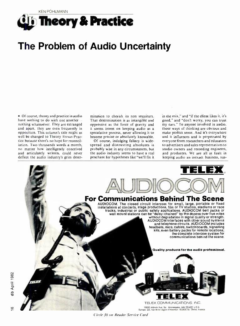
TELEX.
C o IN11 For Communications Behind The Scene
AUDIOCOM. The closed circuit intercom for small, large, portable or fixed installations at concerts, stage productions, film or TV studios, stadiums or race
tracks, industrial or public safety applications. AUDIOCOM belt packs or wall mount stations can be "daisy- chained" by the dozens over five miles
without degradation in signal quality or strength. AUDIOCOM interfaces with other sound systems
and telephone circuits. AUDIOCOM includes headsets, mics, cables, switchboards, signalling
kits, even battery packs for remote locations; the complete intercom system for
communications behind the scene.
Quality products for the audio professional.
TELEX COMMUNICATIONS. INC. 9600 Aldrich Ave So . Minneapolis. MN 55420 U 5 A
Europe. 22. rue de la Légion -d'Honneur. 93200 St Demo. France
< ircle 30 on Reader Service Card

L- Ì- .10dBiD L-19 0dB
THE INTELLIGENT TEST SET
THAT CLEANS UP YOUR ACT.
The Sound Technology 1500A
It's the first microprocessor con- trolled audio measurement test system. It can do in minutes what used to take hours with more conventional and ordi- nary test set -ups. And, it can show you things you've never seen before.
Designed around the most advanced microprocessor hardware, the 1500A will show you the whole story on an inte- gral CRT with adjustable cursor. Push a "Copy" button, and it delivers a hard - copy printout from the optional VP -150 Video Printer.
What Will It Do? Conceived to be the ultimate preci-
sion test instrument for tape recorder analysis, the 1500A evolved into a com- prehensive audio test system for many applications. Here's just a small sample of the varied jobs it will do:
Complete tape recorder mechanical and electronic performance checks Thorough phono cartridge analysis One -third octave spectral analysis
Evaluation of audio quality for VTR's Acoustical room analysis including microphone and loudspeaker measurements Quality control for high speed tape duplication systems Semi -automated production testing Research and development for the audio tape manufacturer Quality assurance for the audio distribution network Exclusive asynchronous inputs and outputs for remote location testing (satellite, transmitter, studios, etc.)
Here's the kind of data you can get: Frequency Response Azimuth at 4 discrete frequencies 2nd and 3rd Harmonic Distortion Vs. Level Wow & Flutter; noise; weighted or flat
Because of the modular plug -in design, the 1500A is designed to grow with you. Many accessories are now available which include a 1/3 octave spectrum analyzer card (noise: 20Hz- 20kHz, Wow & Flutter, .5Hz- 200Hz) that easily plugs into the mainframe; a hard copy printer; a com- prehensive test record that lets you test cartridges, tonearms and turntables; a balancing system that will allow you to interface balanced I/O test applica- tions; and a heavy -duty transport case. There's even a kit for rack mounting.
Add to the above the powerful new GPIB, IEEE interface for computers, and you have an extremely broad range of functions and applications that the advanced 1500A can tackle.
Who Can Use It? Broadcaster. Recording studio. Film
sound studio. Audio manufacturer. Audio dealer. Service technician. Re- searcher. Virtually anyone whose job requires accurate evaluation of audio equipment performance. Wherever you are in the audio spectrum, it can make life a whole lot easier.
Clean up your act with the 1500A. It's intelligent. And so is a phone call to Sound Technology. We'll be pleased to send full information on the 1500A and our other industry standard test equipment.
S SOUND i TECHNOLOGY 1400 Dell Avenue, Campbell, CA 95008
Channel Separation 20Hz -20k (408) 378 -6540 Telex: 357445 Delta Speed & Drift Circle 32 on Reader Service Card © Sound Technology, 1982
CO
pended like Muhammad's tomb some- where between art and science. Seem- ingly no other industry thrives on the incompatibility of its theory and practice the way the audio industry does.
AUDIO AND OBSOLESCENCE The IBM 704 was one of the last
vacuum -tube computers; its 32K core occupied 100 cubic feet. and its instruc- tion time was 12 microseconds. That computer was introduced in 1956 and rendered obsolete in 1959; no one in today's computer industry would use such a machine. But many people in audio still prefer tube compressors of similar- vintage technology. And does the automobile industry still employ its early planetary transmission designs? Many people in audio think certain early tape transports have never been equaled. And does television still use ribbon microphones? A lot of recording engi- neers still regard old ribbon microphones as being their ultimate, secret weapon. In every other industry, progressing tech- nology theory constantly revises industry practices; the audio industry differs - it apparently has compelling reasons to retain otherwise obsolete hardware. And the problem is not limited to equipment usage. Even basic questions remain points of contention. The industry still hasn't made up its mind on the most fundamental questions -what is a flat loudspeaker? How much distortion is
audible? Why does bias linearize analog magnetic recordings? And even con- ceptually -the way in which we view the practice of sound recording- nothing much has changed since the days of Edison and Helmholtz, despite strong advances in research. There exists in audio an underlying backwardness. Of course, there is the argument which defends that troubling state of audio - arguing that since audio is really both an art and a science, both music and tech- nology, it always must be a relative pursuit. But that doesn't provide much comfort. If we followed that line of thought we would be forced to conclude that since audio is subjective, no one ever really knows what he likes.
Is that really the case? Can there be a
question as to what sounds good to us, and what sounds bad? It doesn't seem like it should be a big problem; the task of sound recording and reproduction appears to be eminently reasonable. It's only a question of accuracy -of fidelity. In preparation for our first orchestral recording, a short list could be drawn up with basic criteria to monitor -fre- quency range, dynamic range, clarity. balance, ambience, panorama, spatiality. those sorts of things. Then it should be easy: we have only to listen to our record- ing and vary our technique until the re- produced sound is faithful to the live sound, as according to our criteria. If any disagreement were to arise it would
be a simple matter to walk out into the concert hall and listen to the sound out there.
MICROPHONE THEORY AND PRACTICE
Nell, in practice it isn't quite so straightforward. Immediately we face the fact that although our reproduced sound is good (essentially it reproduces an orchestra), it is also pretty bad (it's nowhere realistic enough to fool anyone into thinking it's a live orchestra playing instead of two loudspeakers). Our recording practice could use some refinement, so we turn to theory to learn more about the idea of placing two microphones some distance up and away from the orchestra. Leaving aside the question of optimal placement. we examine the relative orientation of the microphones themselves. Theory sug- gests that a sensible arrangement might be two cardioid microphones angled out- ward and spaced apart by a head's width. We see that such a pair encodes phase- difference information to produce a very accurate localization. If the two channels are combined into mono, phase cancellation is a problem. but the stereo sounds good. Another possibility would be an arrangement in which coincident capsules utilize intensity differences; this yields good results. and the phase cancellation problem is
eliminated. Further consideration sug-
The Ultimate PORTABLE RECEIVER
for wireless microphones .. , óI -..,.- ,,..,.R
Vega offers the most advdrï Model 66 provides operation superior to the highly successful Vega but in a rugged single unit that is much smaller. (Dimensions: W 5.4" x H 1.3" x Dö. Designed for the professional sound user, the 66's compact size makes it sui-able for mounting to leading portable recòrders, both audio and VTR's. The unit operates from either internal 9V batteries or an existing D.C. voltage source. Contact Vega for complete specifications on this exciting unit.
C Cetec Vega Division of Cetec Corporation P. 0. Box 5348 El Monte, California 91731 Telephone: 1213) 442 -0782 TW
Circle 14 on Reader Service ( and

THE COMPACT TOA MODEL RX -31C MIXING CONSOLE. They're all over the place. From
the big city to the rural recesses of America. And no doubt, many of them are your best customers. Or should be. They're the small churches, synagogues and various houses of worship that need a cost -effective and dependable solution to spreading the word; an affordable sound system controller that gets the message across to the fold without emptying the collection plate -a way to communicate the words and music clearly without garbling missives and slurring sermons. ,
Introducing the TOA Model RX -31C Church Mixer.
The perfect eight by one, tabletop or rack mounting mixer that can be spec'd into the smallest chapel on the stingiest budget.
Engineered with the same reliability and quality performance that is the hallmark of the TOA 900 Series P.A. Amplifiers, the RX -31C ( "C" for church, get it ?) is compact and loaded with the practical, useful features that you need for the church job. Like: effective, five section peaking equalization and built -in high and low pass filters on each input,
mic /line and trim control, channel on/off, phantom power for condensers from a heavy -duty power supply, headphone monitoring, and L.E.D. peak indicators for accurate level control. The 31C is fully transformer isolated on both the in's n' out's which are on XLR's. From a nominal + 4 to a max of + 24 dBm you get performance for any pulpit: 20 Hz to 20 kHz, +0.0 -2.5 dB' less than 0.05% THD (+ 4 dBm @ 1 kHz); and a quiet -132 dBm E.I.N. on hum and noise: to keep the hum out of the hymn. To keep the control setting sacred, an optional attractive cover can be easily fitted over the top panel. To feed a tape machine there's an individual Record Out from the Line feed. Literally, everything you need to convert the tired, worn-out junk and go on your own crusade to go after the new business that's out there waiting for you.
Start with a TOA RX -31C mixer, but don't forget that you've got all the modular TOA 900 Series P.A. components to go with it. The RX -31C has been engineered to be an additional, integral component to an entire 900 Series P.A. system. No
matter which way you turn, TOA has a way for you to get wholly involved in the religious market.
And see a profit. Call us for all the d tails. You just
got the word.
Crafted in Japan. Proven in the States.
TOA Electronics, Inc. 480 Carlton Court, South San Francisco, CA 940 0 (415) 588 -2538 Telex: 331 -332 ® 1981. TOA Elec,«
Circle /7 on Reader Service Card

N
gests a variation of the coincident idea in which one capsule, a cardioid, faces the sound source while the other capsule, a bidirectional, is set 90 degrees off -axis. Theory tells us that a simple sum -and- difference matrix would yield a phase - shifted stereo sound. and since the shift is
electrical, it would be more impervious to mono combining problems. And theory suggests other possibilities -two crossed bidirectional capsules, or sepa- rated omnidirectional capsules, and so on. Thus a quick theoretical examination offers the possibility of AB. XY, MS. Blumlein bidirectional, and spaced -apart configurations. It is evident that each pair type utilizes a different underlying principle, but the similarities are obvious too. All five types could yield satisfactory results with our orchestra recording; we decide to try them all. The results are predictable. In our first try, one con- figuration. let's say the MS. clearly sounded better than the others. But the recording was a little too ambient so we moved the microphone pairs a little closer to the orchestra. And then the XY was our favorite. Obviously the different pairs sound better or worse according to their application. Furthermore. we notice that in some acoustic environ- ments, all of the configurations sound about the same. And so it goes.
The theories underlying each micro- phone type, and the theories unifying all the types seemed consistent enough,
but in practice consistency seems impos- sible. And how many hundreds of examples of that problem do you want? I'll give you two. First -in April, for a live opera recording in Miami, I was depending on MS pairs to again succeed where they had so often previously succeeded. But they produced a test recording in which even the great Pavarotti sounded bad. Eventually an XY system, my least favorite choice, produced a good recording. Second -in May, Robert Shafer delivered a paper at the 69th AES convention ( "A Listen- ing Comparison of Far -Field Micro- phone Techniques" AES Preprint 1753). He played an orchestral recording made simultaneously with three spaced -apart omnis. an ORTF near -coincident pair. and a pair of Blumlein bidirectional microphones. Everyone, myself included, agreed that the Blumlein pair was far superior to the others. What's going on- XY. AB, MS, Blumlein, spaced- apart, DIN (20 cm, 90 degrees), ORTF (17 cm. 110 degrees)? At least in the simple question of stereo -pair microphones, why can't it be ascertained once and for all which configuration is best? Of course, that is an impossible question - individually none of them is any better than any other. No consistency, none whatsoever, not even possible. And of course, that's not surprising. The kind of ensemble, the type of music being played. the acoustics of the hall, all of those
parameters influence specific recording practice. Microphone theory suggests several configurations, but the practical choice of types and placement is strictly a
question of trial -and -error. The only thing positively learned is that the worst - sounding microphone set -up is the one done according to the theoretical rules of microphone placement. It looks great on paper, but the sound is something else. Theory must remain, at best, a
point of departure. It's the old audio problem again- theory- versus- practice, just as discouraging as gravity.
Clearly. as far as microphone philos- ophy and technique go, there is still plenty to disagree on. And the problem, which began simply enough, soon grows quite complex. Apparently, questions of good or bad orchestral sound, this microphone technique or that, must always remain an uneasy, subjective decision- and more importantly, and unexpectedly - it remains a subjective decision in the face of the knowledge that all of us objectively know what an orchestra sounds like. This is a strange idea, and one as difficult to explain as
gravity, but I can at least illustrate the problem. And the illustration paren- thetically leads us into yet another disagreement between theory and prac- tice: what contemporary recording engineer would compromise and settle for two microphones on an orchestra when he could use twenty'?
N you hear
Left to right: Model 70 Model 105 Model 114
Model 116
Garner tape erasers have a reputation we're proud of, and we've earned it.
er audio tape erasers are designed to meet your most exacting standards. Just drop the reel.
cassette or cartridge onto the belt, and, four seconds later, you have a completely erased tape...free of any noise.
Whatever your requirements, Garner has an audio tape eraser designed for you...the machines of the '80's.
Ask about Garner video
tape erasers, too.
Dependability...Guaranteed Garner Industries
4200 N. 48th Street Lincoln, NE 68504
402/464 -5911
arner
Circle 37 on Reader Service Card

IR illiam Shakespeare 1363.1616)
Our considerable DN22 GRAPHIC
experience in the field of EQUALISER
equalisation coupled with a philosophy of continual :- research and development has enabled the realisation of a range of high quality Graphic Equalisers which have become standard tools for correcting room acoustics and offer the solution to tricky equalisation problems.
The latest Klark -Teknik equalisers incorporate scale switching which facilitates a fine resolution for small adjustments and yet retains full boost and cut when required. Construction is to the highest standard using selected components and all units are rigorously bench- tested and aligned before a burn -in period and final music test.
DN27A GRAPHIC EQUALISER
DN3O /30 GRAPHIC EQUALISER
,mn
The DN22 is a dual - channel Graphic Equaliser, each channel having 11 filters providing up to 12dB boost or cut at 11 centre frequencies, covering the entire audio spectrum. Separate low and high pass filters are provided on each channel giving 12dB per octave attenuation above and below their respective turnover frequencies.
The DN22 offers an extremely wide dynamic range and negligible channel- to-channel crosstalk.
The DN27A is the successor to the widely acclaimed DN27. It is a 1rd Octave Graphic Equaliser, providing boost or cut of up to 12dB at 27 I.S.O. centre frequencies covering the entire audio spectrum.
The equaliser filters are of computer -aided design and consist of actively -coupled L.C. networks of the 'minimum phase type. The inductors have precision -ground ferrite cores and coils wound to extremely tight tolerances.
The DN30 /30 Stereo Graphic Equaliser represents a breakthrough in equaliser design, giving two channels of full 1rd octave equalisation in one compact unit. In addition to saving on rack space the DN30 /30 also means a considerable financial saving for anyone requiring stereo system equalisation.
AB -new circuitry developed specifically for the DN30 /30 uses ultra -stable N.I.C. minimum phase, combining filter networks to give unequalled performance.
For further information on our complete range of professional audio equipment and application details telephone 15161249.3660
Klark -Teknik Electronics Inc. 262a Eastern Parkway, Farmingdale, NV 11735, USA. 'Telephone: (51612493660
Klark- Teknik Research Limited Coppice Trading Estate, Kidderminster, DY I 1 7H. England. Telephone: (05621 741515 Telex: 339821
Omnimedia Corporation Limited 9653 Côte de Liesse /Dorval, Quebec H9P 1A3, Canada. Telephone: (5141 636 9971 Circle 39 on Reader Service Card
MOH TEK11111 S(H(T3d S('!('ll('('

N N
tHudio îapa' professionals rofessionals
REEL TO REEL TAPE Ampex, 3M. All grades. On reels or hubs.
CASSETTES, C- 10 -C -90 With Agfa, TDK tape.
LEADER & SPLICING TAPE
EMPTY REELS & BOXES All widths, sizes.
Competitive! Shipped from Stock!
Ask for our recording supplies catalog.
Poly 3121298 -5300 1233 Rand Rd. Des Plaines. IL 60011
Circle 25 on Reader Service Card
Noise Suppression &
Power Protection
MIME Model PS -1
The PS-I is a power line conditioning unit designed to protect audio equipment from high voltage transients and RE interference. Three neun lamps indicate relative phasing of the line. neutral and ground connections. A latching relay helps to avoid amp speaker damage due to power up transients generated after a temporary lass of power. Ask your local music dealer for more details.
Linear & Digital Systems, Inc.
40 Marco Lane. Centerville. OH
45459 (513)439.1758
Circle 2/ on Reader Service Card
BEETHOVEN AND MICROPHONES
Last winter, a single -blind test was given to some music engineering students at the University of Miami by the illus- trious John Woram. (Freelance writer's rule number two -flatter the editor no matter what kind of person he really is.
The first rule is to say something nice about the publisher, but that is usually impossible.) Mr. Woram had taken two LP recordings of the last movement of Beethoven's Ninth Symphony. one a
contemporary performance with the Berlin Philharmonic recorded with multiple microphones, and the other an early stereo recording also with the Berlin Philharmonic recorded with per- haps two or three microphones. He copied parts of the two performances onto tape and smoothly edited between the recordings, switching back and forth between them. The students listened to the recordings; the alternating sections were evident but both recordings were full -fidelity reproductions. There were many differences and relative strengths and weaknesses, but there was no imme- diate way to guess which was twenty years old. and which was contemporary.
Finally, after repeated hearings, the consensus was that one of the recordings was a little more "up- front" and "tighter" and "cleaner," while the other was a
little more "distant." Suspecting a trick, second -guessing that the "better" sound was from the old recording, most of the students picked the "cleaner" recording, the one finally perceived as being better. as the old one. They were wrong. of course. The tight and clean recording was the new multitrack recording. obviously. How could it be otherwise? That record- ing technique details every orchestral section. bringing every part up to the fore. Every part is audible, unnaturally audible. And that's a problem. The kind of sound which has popularly come to be identified as good or correct is a
wholly artificial sound, a pan of mono- phonic point sources. The old coincident - pair Beethoven recording was an ac- curate reproduction, precisely encoding both panorama and depth; it reproduced the orchestra as it really sounds in the concert hall- violins on the left and violincellos on the right, and more importantly. soloists in front and then the orchestra. and the chorus in back. But the real dilemma is that the students knew all of that. They realized that one recording was a more realistic recording. They outwitted themselves because the force of gravity was too much -they had already decided that the clean and tight recording was the better one. even though each of them knew exactly what a
live orchestra sounds like. There is no need for any more com-
mentary; it's the same old problem with audio, that strange kind of perversity which makes us agree that an orchestral recording is a good recording, when in fact we also agree that the orchestra
performing in the hall sounded quite different.
Well, I'll confess that l've painted an especially unfair picture of the situation; there is more to audio than incoher- ence and confusion. Significant research has been 'accomplished and the quality of both hardware and software continue to improve markedly every year. And as
far as some of the inconsistencies l've pointed out, they are excusable because the audio profession must always meet the tremendous challenge of touching, and collaborating, with art. And in deal- ing with art, grim determination to get it right is the only important criteria. At the point of the bass soloist's entrance in Beethoven's Ninth Symphony, the paper of the autograph score has a hole worn through it because Beethoven wrote and erased that entrance over and over until it was right. He had to be demand - ing-it was the first time a vocalist had appeared in one of his (or anyone else's) symphonies. And the audio profession is always trying something new too, with the same admirable persistence.
But on the other hand. consider -a twenty year old recording is a more ac- curate reproduction than a new one. We should limit our praise for an industry in which that is possible. and sometimes common. So, what is to be done? Noth- ing, probably. Muhammad's tomb will remain suspended between heaven and earth until the end of time. And it will probably take that long for the audio in- dustry' to agree on a flat loudspeaker, or discover the true meaning of quad. Theory- versus -practice, forever.
Introducing... KEN POHLMANN
Effective this month. Ken Pohl- mann takes over our fheory and Practice column. as Norman Crow - hurst departs to pursue other interests. Ken is the Assistant Director of the Music Engineering Program at the University of Miami. and has served as chief recording engineer and audio consultant for the Miami Opera's National Public Radio broadcasts. He holds Bachelor and Master of Science degrees with high honors from the University of Illinois. and for his Master's thesis designed and built a real -time hybrid computer music system for that university's Experimental Music Studio.
Pohlmann is the founder and co -owner of Microcomputer Arts, Inc., a free -lance design engineer for International Business Information Systems. and has served as engineer, producer and composer on many contemporary music sessions in this country and in Europe.
No doubt he'll be giving up most of the above. now that he's writing a
monthly column for us. And then again. maybe not.

Great announcer mics should be heard and not seen.
You won't see the MCE 5. but you will hear the rich full frequency sound that tells you its a Beyer. Now the top quality and reliability for which Beyer is famous has been packaged into the world's smallest broadcast microphone - the MCE 5 - the an- nouncer's mic.
The MCE 5 is an omni -directional electret condenser microphone with 20Hz -20kHz ± 3dB frequency re- sponse. 62dB signal -to -noise ratio and a maximum rated SPL at 1kHz of
116dB. Its matte black finish will not reflect light. so it goes unnoticed on camera. And Beyer's unique floating element eliminates pick -up of clothes rustle and body movement. Wind and air noises are reduced by up to 20dB. with the (removable) windscreen. You get only the announcer's voice.
Unlike conventional mini mics that are Subject to breakdown from tem- perature and humidity. the MCE 5 is
specially designed to withstand the elements.
The Beyer MCE 5 is available in a variety of configurations and connec- tors including: balanced. unbal- anced. XLR. 1/4-inch and open end: as well as phantom and self -powered with its own battery.
You may not find the Beyer MCE 5 on our announcer, but you'll find it at your local Beyer dealer. today
Bever)))) Dynamic
ACTUAL SIZE.
BEYER DYNAMIC, INC. 5 -05 Burns Avenue. Hicksvtlle. NY 11801
(516) 935 -8000 In Canada. H. Roy Gray. Ltd.
Can you find it?
Circle 27 oil Reader
Service Card

N
LEN FELDMAN
found With Images
Another David & Goliath Scenario
Back in the 1940s and early 1950s, an unbelievably prolific inventor by the name of Edwin H. Armstrong was busy fighting some of the then giants of the electronic industry- hoping to sub- stantiate his claims for payment of royalties for having invented radio circuitry which is still in use today. Before the ultimate victories, Major Armstrong leaped to his death from his apartment in New York. leaving his widow to collect millions of dollars from some of the defendant corporations with whom he had been in litigation for years before his death.
Later, in the 1950s and early 1960s, another almost equally prolific inventor by the name of Murray Crosby fought a
losing battle against the likes of such giant corporations as General Electric and Zenith. Crosby's system for trans- mitting stereo sound over FM radio was one of five that were considered by the FCC. after extensive field and lab testing. Though many still feel that the Crosby system was technically superior, the FCC selected a system which had been pro- posed by General Electric and Zenith (actually, their two systems differed in minor details but were made identical and became known as the GE- Zenith system). That system is, in fact, still used today.
As almost everyone who owns a stereo FM radio knows, in all but the strongest of signal areas, stereo FM reception is
far noisier than the same program received in its equivalent monophonic form. Such would not have been the case had the Crosby system prevailed. And since, in those days, most of the world looked to the U.S. for leadership in
communication technology, nearly all industrialized nations adopted the sanie stereo FM system as that used in the United States.
All of which brings us to the present. As I mentioned in this column a few months ago, an industry committee is
now in the midst of deliberations con- cerning the choice of a system to be used for stereo and /or bilingual audio trans- missions on TV. Of the three systems under consideration, two come from familiar sources. One, of course, is
sponsored by the Electronic Industries Association of Japan (EIAJ). It is, with minor modifications, the same system which has been in use commercially in Japan for more than three years. Were it to be adopted as a U.S. standard, Japanese manufacturers would have things pretty easy, since common audio multiplex circuitry could then be used in sets destined for the domestic Japanese market as well as the export market to the U.S.
The second system under considera- tion is one proposed by Zenith Radio Corporation, the well -established U.S. manufacturer of TV sets and other electronic communications products. Remember, too, that Zenith shared a
victory (with G.E.) in the matter of stereo FM broadcasting mentioned earlier. While the EIAJ system utilizes an FM subcarrier for transmission of the stereo "difference" (L -R) audio information, the Zenith system resorts to a suppressed - carrier, double -sideband AM subcarrier for transmission of that same informa- tion. In that respect, the system proposed by Zenith is very similar in concept to the system used for stereo FM broad-
casting. Instead of requiring a pilot carrier (such as the 19 kHz pilot signal used in stereo FM), the Zenith system utilizes the already- present horizontal sync pulse, at a frequency of 15,734 Hz (in the case of color transmissions). Their suppressed AM sub -carrier is at twice that frequency, or at 31,468 Hz.
BUT WHO IS TELESONICS? I he third system for stereo TV audio
being considered is one proposed by Telesonics Systems, Inc., located in Glen Ellyn, Illinois, a near -suburb of Chicago. I recently met one of the principals of the company, James R. Simanton. Simanton, I discovered, is an electronics engineer and nuclear chemist who now leads a research and develop- ment group consisting of 25 scientists, engineers and technicians working at the forefront of electronics and computer technology at a major nuclear research laboratory. In other words, Telesonics Systems, Inc. is a sideline of Simanton's who, along with another scientist - inventor, Carl R. Wegner, formed the company for the primary purpose of promoting the Telesonics Stereophonic Television Sound System. The system is covered by two granted U.S. patents with a total of 65 granted claims. Wegner is the actual inventor and has several other granted patents covering many facets of transmission and reception for a high - fidelity stereophonic TV sound system. A veteran of more than 20 years in the electronics field, Wegner has created an impressive volume of sophisticated, state -of- the -art equipment and instru-

Beginning as a Nashville session musician with a burning desire to be a producer, Larry Butler watched and listened. His first break came when he got a producer job with Capital Records in Nashville. The first record he ever cut, with Jean Shepard, was a hit. Since then he has cut over 50 gold and platinum records as producer for CBS, Johnny Cash Productions, Tree International, United Artists and now as an independent. His recent relationship with a man named Kenny Rogers, has produced hits like Lucille, She Believes In Me and The Gambler. Larry won the Grammy Award as producer of the year in 1980.
ON DEVELOPING A STYLE When I started producing, I was producing
like everybody in town. I started to produce a record like Billy Sherrill would do it or like Owen Bradley would do it or whatever. And then one day I listened to a lot of records I had done and I
thought now wait a minute. If somebody wants a record that sounds like a Billy Sherrill record they can go get the real thing. So I started producing the way I wanted to produce. It was a great lesson for me. It was a big turning point in my career. I
think that nobody is really going to sell or really succeed until they reach that point where they're putting themselves into it, instead of making a copy of someone else's work:'
ON REACHING THE LISTENER "I'm a believer in the simplicity of a song.
I believe in laying something in somebody's lap they don't have to search for mentally. I've said this before, if a guy's driving home from work he's got a million things on his mind. He's got to spank the kids when he gets there. He's got a flat tire on the way home. And through all of this there's a song. He's got his radio turned down kind of low and a song cuts through all of that and he finds himself humming along with it. When that happens you've hit one in the upper decks:'
ON KENNY ROGERS Kenny is such a univelsal name, such a big
name. I try not to let any prejudice enter into comments about Kenny because we've been so close, but I guess he has to be the strongest single male artist in the United States. I can't think of anybody that's reaching the mass of people that he's reaching and I think it's unfair that people say he's the new Elvis. Well, there's never going to be another Elvis. There's Elvis Presley. That's it. Forever. But as far as sales. you might compare them:'
ON KNOWING WHEN TO STOP "I think the most common mistake for an
engineer and producer to make is maybe not really realizing the take when they've gotten it.
Sometimes going too far because they're looking for that emotion or magic. Sometimes you can have it and not realize it. Sometimes you can have maybe one guitar part that bothers you, so you go ahead and do another take. Well, you have gone by the one that had the feeling, the one that had the emotion:'
ON TAPE "I use the philosophy and theory of sur-
rounding myself with people who know what the hell they're doing and letting them do it. I let the engineer do his job.
The only things I've heard them say about 3M is it's dependable, you can trust it, you don't have to worry about it. When you're spending money and you get good service you're not going anywhere else. You're going to stay there with whoever it is.
I just know 3M has always been very, very open for ideas and suggestions. It's just like "money making music:' Three M's. That's the way I think of the tape, because it works and it sounds great:'
SCOTCH 250 WHEN YOU LISTEN FOR A LIVING.
neticA /V Products Division /3M

THE ALL NEW SWINTEK
DESIGNER SERIES FEATURING SWINTEK ROAD
SHOW RELIABILITY AND:
BODIES in BLACK CHROME, GOLD or SILVER to compliment the attire and highlight the production
HEADS including BEYER M500 or SHURE SM85 for vocal excellence
ENGINEERED with DBS com pandors utilizing BANDWIDTH REDUCTION for future use with LPTV
-Swink* TELECOMMUNICATIONS DIVISION 1180 Aster Avenue, Unit J. Sunnyvale. CA 94086 (408) 249 -5594 TELEX #172 -150 SUVL SWINTEK
Circle 43 ou Reader Service Card
mentation covering virtually all cate- gories of electronic technology. Other members of this tiny corporate entity include a patent attorney, Eugene Cummings, who is a member of the firm that helped Wegner prepare his patent applications, and several inactive in- vestors who provided the "seed money" for their fledgling corporation. Given this sort of "basement lab" background. I was nothing short of amazed that Telesonics had managed to get as far in the stereo TV sweepstakes as it had! Clearly. they must have demonstrated sufficient technical merit to those sitting on the industry committee charged with testing and evaluating all proposed systems to have remained a contender for this long -right up through the re- cently completed on- the -air field tests which took place over public radio station WTTW, in Chicago. I decided to find out all I could about the Telesonics System.
While I haven't spoken with Carl Wegner as yet. I recently spent several hours with Jim Simanton. I learned that his career has spanned technical and administrative positions in industry and in university scientific research. Among his accomplishments was the co -dis- covery of long -lived Aluminum -26, an intensively sought radio -active tracer. This feat was acclaimed as the foremost research event of the year in which it occurred (1954). Simanton was also the inventor of nuclear particle instrumenta- tion now used in all modern accelerators. He and his associate. Carl Wegner. were also the inventors of commercially produced intelligent computer graphics terminals. Here, I concluded, were two men fashioned much in the mold of Armstrong and Crosby. Could these " Davids" succeed in the face of a pair of " Goliaths" the size of Japan, Inc. and Zenith? Only time will tell.
As for the Telesonics System itself. upon first inspection I felt that it differed little from the already -proposed Zenith system. That is. it utilizes a suppressed - carrier, double sideband AM sub - carrier system for transmission of the stereo difference information. Further- more. it does utilize a pilot carrier -this time at a frequency of 19,667.83 Hz. or exactly 5 4 of the horizontal line fre- quency used in NTSC color trans- missions in the U.S.. Canada, Mexico and Japan. This places the center - frequency of the suppressed sub- carrier at 39,335.66 Hz -not all that far from the 38 kHz frequency currently used in stereo FM radio broadcasting for its sub- carrier. With so many similarities between the Telesonics system and the competing Zenith system as well as long - established stereo FM broadcast systems, I wondered how the people at Telesonics were able to acquire such strong patents as they did. I soon learned that some very important interactions between the video and audio portions of a composite stereo
TV signal prompted Telesonics to choose the precise baseband frequencies that they did.
Before I spoke to Simanton I had concluded (simply from my knowledge of stereo FM) that any system proposing to use an all -FM sub -carrier for stereo TV audio (in this case, the EIAJ) was hound to produce audio having a better signal -to -noise ratio than any system using an AM sub- carrier (suppressed, or otherwise). You probably would have guessed the same; after all "FM is always quieter than AM," right? Well. Simanton set me straight on that point, by showing me how. because of a poor choice of sub -carrier frequencies. har- monics of the line- repetition rate of the video signal can cause interference with the audio signals recovered in a stereo TV system. He demonstrated how signal - to -noise ratios can vary with varying video scenes. both in color and black - and -white and how, by a very careful analysis. he arrived at the particular center- frequencies for his system's sub - carrier. By centering his suppressed sub -carrier between the second and third harmonics of the horizontal (video) scanning frequency, interference from video to the stereo difference(L -R) audio component is reduced to a single compo- nent at approximately 7.8 kHz instead of three components at 6.5 kHz, 9.25 kHz and 2.75 kHz. While Simanton contends that in the coming era of stereophonic TV his system will perform best if TV manufacturers revert to split -sound (separate I -F sections for video and audio carriers) circuitry as opposed to some- what less expensive " intercarrier" TV set designs (which utilize only a single intermediate frequency section and recover audio as a 4.5 MHz difference signal between video and audio RF frequencies), he also proved. to my satisfaction. that if set manufacturers continue to sell intercarrier -type sets when stereo TV comes. the Telesonics System would be the only one that would provide tolerable performance under those conditions as well.
The lab and field tests are over now. and Jim Simanton was present during all of them and has had an opportunity to review the results of these compre- hensive tests. While pledged not to disclose the results of the test until they are officially submitted to the FCC in the form of a report and recommenda- tion by the EIA committee charged with this work. Mr. Simanton seemed com- pletely pleased with the way his system fared. He is convinced that if a system is
chosen strictly on the basis of merit, in terms of quality of audio reproduction. his system will be the winner. If his prediction turns out to be true, it will be
the first time in anyone's recollection that "David" prevailed against a couple of "Goliaths " -unless you count that first slingshot episode that took place about 3000 years ago!

r
The Lexicon 1200 has a wideband twin! With the Lexicon Model 1200, you can speed up
taped material, or slow it down, and still maintain true broadcast -quality sound.
And now the 1200 has a wideband twin: the Model 1200B.
The 12008 does everything the 1200 does, with the added feature of wideband (15 KHz) operation to meet network N and AM radio broadcasting standards.
Like the 1200, the 1200B automatically reduces or expands the playtime of recorded material. Commercials can be tailored to fit with the push of a button. Tag lines
are easy to add. Taped newscasts can quickly and easily be tine- adjusted. All without loss of audio quality.
Lexicon Audio Time Compressors work with virtually any variable -speed tape recorder or variable -speed projector and/or videotape recorder.
Write for detailed information and application notes today.
60 Turner Street Waltham, MA 02154 1617)891 -6790 /TELEX 923468
Epot GOthdrtt HmOlt CorRa . rlEw 1crk. 1C014
Circle 40 an Reader Service Card

Cancer isn't just a grown -up disease.
Cancer is the number one killer disease of thousands of children each year. Time is running our for many of these children, but with your support the research can continue and the cure will be found.
For information on how you can help please write St. Jude Children's Research Hospital, 505 N. Parkway. Box 3704, Memphis, Tennessee 38103, or call 1 -800- 238 -9100.
' ST. JUDE CHILDREN'S RESEARCH HOSPITAL Danny Thomas. Founder
JOHN EARGLE
ØJ,j) Sound Reinforcement
High- Frequency Horns and Acoustic Lenses: Part
1.25
1.00 d,,.r Resielance
,r5 _
S, s: .50
.25 Reactance
u I 1
8 10 X -+t (A)
Figure 1A. An infinitely -long exponential horn.
1131
Figure 1B. Radiation resistance and reactance for an infinite exponential horn.
(C)
Figure 1C. A finite horn.
There are five basic types of horns which we will discuss: multi -cellular horns, radial (sectoral) horns, horn lens combinations, diffraction horns and con- stant- coverage horns. Together, they form the basis of high- frequency design for most high -level sound reinforcement applications. While the newer constant - coverage horns have solved most of the pattern control problems inherent in older designs, there are certain applica-
4
nf, (D)
10
Figure 1D. Radiation resistance and reactance for a finite horn.
tions in which the less- than -perfect char- acteristics of the earlier horns may be de- sirable.
ideally, a horn should efficiently cou- ple the high frequency driver's output, and produce a smooth, extended re- sponse. It should also exhibit smooth dispersion over its operating range. Horns have become better in recent years, but there are still compromises inherent in all designs.

Think of us as your
mike expert.
The 635A- Perfect design from the start
The Electro -Voice 635A is probably the most widely used broadcast microphone currently available. Yet it was introduced back in 1967! There are microphone companies that haven't been around as long as the 635A! What makes a micro- phone continue to be the broadcasters' favorite after 15 years in the field?
The 635A was designed to be used anywhere. Its screw- machined steel case and mechanically nested parts set stan- dards for durability and ruggedness that the competition still strives for. It was the
first omnidirectional microphone design- ed to have a shaped, rather than flat. frequency response. A rolled off
bass response combined with a slight- ly rising high end make it perfect for vocal reproduction. And it was the first micro- phone of its type to feature an elastomer
encased head capsule for reduced handling noise and additional protection from severe mechanical shock.
Despite all the technological ad- vances in the broadcast, recording and sound reinforcement industries, the 635A continues to be the "audio man's screwdriver " -a microphone tool that can be used anytime, anywhere, for almost anything. When a product is designed right to start with, there's no need for it to become obsolete. All Electro -Voice professional microphones are designed with the same goal in mind. That's why people think of Electro -Voice as their microphone expert.
8ectro:Voicé a gukon cowpony
600 Cecil Street. Buchanan. Michigan 49107
In Canada Electro- voice. Div. of Gution Industries (Canada) Ltd .
345 Herbert St.. Gananoque. Ontano K7G 2V1.
Circle 38 on Reader Service Card

(A)
Figure 2A. A typical 2 x 5 multi- cellular horn (Altec photo).
We will begin our survey of horns with a look at an infinitely -long exponential horn, as shown in FIGURE I. The horn's cut -off frequency, j, should be at least one octave below the lowest frequency at which the horn is expected to operate.
The graph in FIGURE IB shows the re- sistive and reactive loading of an infin- itely -long horn. Note that when the ratio off to J; is 2 (or greater), the leading ef- fect is mostly resistive.
Of course, there are no infinite horns, and the typical horn will present X, and R, curves which have "lumps" in them due to reflections from the discontinuity of the mouth back to the driver. These conditions are shown in FIGURE IC and ID.
To determine the shape of the horn, we begin by calculating the flare constant, m, which will determine just how rapidly the horn flares out as the distance from the throat increases. The equation is:
in = 47rf, c, where m = the flare constant,
= the cutoff frequency, and c = the speed of sound.
At any point along the length of the horn, its cross -sectional area may now be
found from the equation
S, = S,e 'm
where S, = the cross -sectional area at a
distance, x, S, = the cross -sectional area at
the horn throat, e = 2.718,
m = the flare constant, and v = the distance from the throat.
d
d A'
120
c ö,110 0
0. 100
ó 3 0 ..
E
m
160
150
140
130
90
80
70
60
50
40
30
6543 2
1
s
-2
25
6
p Number of cells s
5
` 1 i
1 11111 lo 'loo 1000
Frequency, Hertz
(B)
Figure 2B. Theoretical beamwidth for multi -cellular horns (data from Beranek, Acoustics, McGraw -Hill, New York, 1954).
If the circumference of the horn mouth, divided by the longest wavelength to be
reproduced, is greater than about 3 (i.e., c,,,, Am > 3), then the horn will behave approximately as though it were infinite, with a quite smooth resistance.
THE MULTI -CELLULAR HORN Although a simple exponential horn
provides ideal loading for a driver, it does tend to focus high frequencies along the axis of the horn. The multi -cellular horn. developed in the early thirties by Wente and Thuras, was the first attempt
m
10,000
to overcome this problem of high - frequency narrowing. A group of expo- nential horns, or "cells," were clustered together, as shown in FIGURE 2A, and each cell was expected to control radia- tion in its own direction. The ideal per- formance of the multi -cellular group is
shown in FIGURE 2B. In reality, perform- ance is not this good, especially at high frequencies. "Fingering" is the problem; the cells interfere with each other and produce "hot spots" along the common edges between the cells. FIGURES 2C and 2D show this tendency for a two-by -five multi -cellular horn. The depth of the
,.
Figure 2C. Polar response of a 2 x 5 multi -cellular horn at 2 kHz (horizontal, dashed line: vertical, solid line).
á

YOU CAN HAVE A COLUMBIA RECORDS
RECORDING CONTRACT Columbia Records and the American Song Festival' have joined forces to offer talented performers an unprecedented opportunity to receive a fabulous contract to record and release an album. Columbia Records is looking for new performing talent, and for original record concepts and ideas. Columbia Records releases and promotes all kinds of music: Pop, Rock, Jazz, Folk, Country, R & B, Soul, Classical, Gospel, etc. No matter what kind of music you per- form, there may be a place for you on the Columbia label.
In its first 8 years, the American Song Festival has awarded over $700,000 in cash prizes to winners of its lyric and song writing competitions. Even more impor- tant, hundreds of winning songs have been recorded by major recording stars. Plus grand prize winning songwriters have recorded their own songs for the top labels, and have #1 singles and #1 albums to their credit. It could happen to you.
All you need is a simple home demo to display your performing talents. You define the type of music on your tape and the American Song Festival finds the right people in your style of music to do an honest appraisal of your artistic endeavor. The top pros in the music industry will listen to your work. Imagine being able to audition for a record company, a music publisher, an artist manager, and a record producer all at once. That's the kind of exposure you could receive.
If you want to further your career and record for Columbia Records, the first step on your path to suc- cess is to mail the coupon to:
American Song Festival Recording Contract Search 5900 Wilshire Boulevard Los Angeles, CA 90036 © 1982 American Song Festival
OR CALL TOLL FREE: In the Continental United States (except California) 800 -421 -4212 In California 800 -252 -2252 Columbia is a trademark of CBS Inc.
Send to: American Song Festival, Recording Contract Search 5900 Wilshire Boulevard, Los Angeles, California 90036
Please send me free details of the Columbia Records Recording Contract.
Name
Address
City State _ Zip A Presentation of Sterling Recreation c 1082 American Song F rival UBIIC
Circle 22 an Reader Service Card

fingering approachs 10 dB at the highest frequencies.
Multi- cellular horns have been largely replaced by the newer constant -coverage horns in modern speech and music reinforcement work. However, they are still found throughout the motion picture industry, which seems reluctant to give them up. They come in a variety of configurations with various cutoff frequencies. The most common con- figurations are four -by -two. five -by -two and five -by- three.
RADIAL HORNS I hese devices are so -named because,
when viewed from above, they resemble a sector of a circle, with the straight radial boundaries characteristic of a sector. They may also be referred to as
sectoral horns. Top and side views of a
90° x 40° radial horn are shown in FIGURE 3A. The typical directional characteristics of such a horn are shown in FIGURE 3B. In these graphs, we have plotted the included angle over which the response is no more than 6 dB down from the on -axis response. Note that the wider horizontal angular coverage of 90 degrees can be maintained fairly well, due to the large mouth dimension in that plane. Since the vertical dimension is fairly small, its pattern control is poor at low frequencies. In keeping with its expo- nential cross -section, the vertical pattern control narrows with rising frequency.
For many applications, the vertical narrowing of a radial horn is a benefit. Where horizontal coverage is the main concern, the rising directivity in the vertical plane acts to "equalize" the driver's high -frequency response by an amount equal to the horn's directivity index. The directivity index is shown in FIGURE 3C.
There are more sizes and shapes of radial horns than all other types, and the user can pick and choose as required for the application at hand. One point to watch for is the high -frequency hori- zontal coverage. Many horns tend to narrow in the horizontal plane above about 8 kHz because of poor flare de- velopment in the throat region. Through careful attention to throat design, a
radial horn can maintain excellent coverage out to 16 kHz in the horizontal plane.
Manufacturers generally publish coverage data on radial horns in the form of -6 dB horizontal and vertical coverage angles, as well as plots of directivity index (Dl) and directivity factor (Q). DI (in dB) and Q (a ratio) are measures of the power radiated along the axis of a loudspeaker relative to that same power radiated equally in all direc- tions. We will discuss DI and Q in greater detail in a future column.
Next month, we will continue with a
discussion of the horn( lens combination, diffraction horns. constant -coverage' horns and distortion in horn systems.
(D)
Figure 2D. Polar response of a 2 x 5 multi- cellular horn at 10 kHz (horizontal, dashed line; vertical, solid line).
Figure 3A. The radial horn.
Figure 38. Horizontal and vertical beamwidth of a typical 90 x 40 radial horn (JBL data).
Figure 3C. Directivity Index (DI) for the radial horn whose beamwidth data is shown in Figure 3B.
400
2200
. 150
140
g 1051
TOP VIEO SIDE VOW
o
415 n?0
15
In
Hoarnnmi
1 251 5014 SK
Frequency. quency. Her, 181
'315 640 I._SK 2.50K SK IOK 20K
Fre,ulenc5. lleno ICI

MICROPHONES! At long last, all the questions you ever asked ... all the problems you ever grappled with ... are answered clearly and definitively.,
micriihone Hamiboek
In 256 fact -filled pages, liberally sprinkled with over 500 illuminating photographs, drawings and diagrams, John Eargie covers virtually every practical aspect of micro- phone design and usage.
The Microphone
Completely up to date, this vital new handbook is
a must for any professional whose work involves microphones. Here are just a few of the topics that are thoroughly covered
Directional characteristics -the basic patterns. Using patterns effectively. Microphone sensitivity ratings. Remote powering of capacitors. Proximity and distance effects. Multi- microphone interference problems. Stereo microphone techniques. Speech and music reinforcement. Studio microphone techniques. Microphone accessories. And much, much more!
THE MICROPHONE HANDBOOK. You'll find yourself reaching for it every time a new or unusual problem crops up. Order your copy now!
JOHN EARGLE noted author, lecturer and audio expert, is vice-president, market planning for James B Lansing Sound He has also served as chief engineer with Mercury Records, and is a
member of SMPTE, IEEE and AES. for which he served as president in 1974 -75. Listed in Engineers of Distinction, he has over 30 published articles and record reviews to his credit, and is the author of another important book. Sound Recording
528.50
r
ELAR PUBLISHING CO., INC. 1120 Ola Country Roaa, Plainview, NY 11803
Yes! Please send _ copies of The Micro- phone Handbook ar 528.50 per copy. (New York State residents add appropriate sales tax.
E Payment enclosed. Or charge my F. MasterCard f Visa
Acct. # Exp.Date
Name (please print)
Address
City
State /Zip
Signature
Outside U.S.A. add 52.00 for postage. Checks must be in U.S. funds drawn on a U.S. bank If you aren't completely satisfied, you may return your copy In good condition within 15 days for full refund or credit.

M
Editorial
L LIAI.Y. tttt:RES HIEN no shortage of commentary about
the citizen's right (or lack of it) to use the airwaves for various purposes, some of which turn out to be potentially illegal.
No doubt the biggest attention- getter has been the on- going efforts of Walt Disney Productions to prevent the private use of home video recorders.
Arguments by the Disney organization and others have persuaded the Ninth U.S. Circuit Court of Appeals to hold that off- the -air recording of Copyrighted TV programs is an infringement of Copyright law. In other words, if you press the record button on your Betamax while watching your favorite soap opera, you're a crook.
Sony is fighting the decision, in order "...to defend the consumer's right to use their machines." Possibly. they're thinking about future VCR sales as well, although the recent press releases haven't mentioned this. Oh well. they can't be
expected to remember ever7ihing. A little closer to home, the National Association of Broad-
casters has also been considering their position on public 'o\ nership" of the airwaves. That position is: the government may need to regulate the use of the broadcast spectrum- if only to maintain order- but it has no right to regulate the program content.
And even closer to home. we've been considering our own position on the subject. So far. we're still in the considering stage. The livelihood of most of our readers depends on a
healthy market for recorded and broadcast audio. And while it's fun to live in Disneyland and sing "Heigh -ho, heigh -ho. it's off to tape we go" while letting others worry about legal niceties. the Grumpys in the crowd keep reminding us that the consumer had better keep buying our stuff, or we're all going to he in big trouble.
Well now. is Uncle Sani (or possibly Uncle Remus) helping or hurting us by intervening in the fine points of broadcast transmissions? The more we think about this. the more con- fused we get. Does anyone know where Joseph Heller lives? We think we've discovered Catch 22.5.
Consider the drug -crazed purse snatcher who sinks even lower down on Society's ladder. Now he's making videotape recordings of The Wonderful World of Disney." And what's he going to do with them? He's certainly not going to rent them out. Why. Walt Disney does that himself. Just walk into any video emporium and for five bucks you can rent Mickey, Donald and all the gang. Yes, that's the same Disney who's suing the world for recording off -the -air. But this, of course. is different. (Make that Catch 23.)
Getting back to those illegal off- the -air recordings, if they fall into the hands of unsuspecting viewers, the net result is that the program has reached an even -wider audience. That means more exposure for the artists, sponsors and all concerned. Isn't that terrible? Well. uh
Now that we've settled that one, let's move along to off - the -air recording of radio programs. Here, the broadcast that is being taped is usually of a commercially -available product (no doubt, engineered by a db subscriber). The listener recordist saves himself a few bucks by taping his music. rather than buying the record at the store.
Obviously, the direct consequence is a loss of revenue to the record company, the artist, and eventually to the recording studio, when and if the record companies feel the pinch. It certainly sounds illegal. But it isn't. Some ten years ago. Congress ruled that off -the -air audio recordings for personal
use were not subject to the existing Copyright laws. (For more details on the subject, and some possible future changes, see
Len Feldman's Sound With Images column in our February issue.)..
So the situation stands as this: off- the -air (video) tapings, which help the artist. are illegal. Off- the -air (audio) recordings, which hurt the artist, are not illegal. No doubt. all of this makes perfect sense to a lawyer, and as soon as we find one who can explain it to an editor, we'll pass along the word.
And in the meantime, from that wonderful state that brought us Ronald Reagan, comes word that the tax department is re- examining the recording industry. in an apparently heavy - handed attempt to dig up some extra funds to re -stock the treasury. According to a press release from the newly-formed California Entertainment Organization (CEO), the state's Board of Equalization (SBE) has just "reinterpreted" the Revenue and Tax Code.
The CEO notes that all independent producers, engineers, production companies and recording studios in that state must now pay a six percent sales tax. Independent engineers are now told that they should have been charging sales tax and are subject to retroactive penalties and interest for failing to do so.
That "retroactive" part bothered us, and so we did a little "Sacramento snooping" to see what we could discover. When contacted by phone. no one at SHE seemed to know what we were talking about. (That's certainly happened to us before.) An SHE staff member thought that while recording services are not taxable. the record fabrication process is. That leaves unanswered the question: What goes on in the recording studio? (Save the wisecracks: we mean. is it a service or a
fabrication process?) Our personal opinion doesn't really matter. What does
matter is how the law is interpreted. As far as we could dis- cover, there have been no recent changes in the law, although "interpretations" come and go. almost with the tides. This season's interpretation seems to be: "Let's get the recording engineers- everybody knows how rich those guys are."
While awaiting further enlightenment. we'd like to pass on some friendly advice to the California recording industry: You may be under close examination (remember, you read it here first). Once a precedent is set (of forcing sales tax out of some engineers), it becomes easier to prosecute the entire recording industry. According to CEO. "Capitol Records. Warner Brothers. Chrysalis. A & M (and others) have already been served with sales tax bills. Many have had to pay and arc now in court. By law. the state has the power to impose taxes and collect them by any means it deems suitable. The law also states that in order to fight the tax, you have to pay it first."
The CEO has been formed to fight the tax and defend the recording industry against enemy attack. While there are already quite enough special interest lobbies around which try to shelter their members against meeting their obligations as citizens, we've heard enough taxation horror stories to know that all of us need all the protection we can get. No, we're not quite in the same boat with Solidarity (yet), but this is one little facet of Americana in which the average citizen is always guilty until proven innocent. The CEO thinks you're innocent. According to a spokesperson, "In the past, we've been guilty of getting together once a year and putting on our tuxedoes for the camera. This time, if we don't get together and fight, we're dead. It's that simple."
You can get in touch with the California Entertainment Organization at P.O. Box 512, Van Nuys, California 91408. Or call (213) 906 -2080. JMW
Circle /5 on Reader Service Card i

SIOPI PSI `PIoo aLI,L

MCI invites you to compare specifications for the JH -11OB against those of any other tape recorder on the market today. No pretty pictures, no bright copy, just facts. The JH- 11OB...unsurpassed in a field of professionals. And that is a cold, hard fact.
Unless otherwise specified, the following conditions apply to all graphs:
Speed: 30 ips
Overbias: 1.0dB @ 10kHz Fluxivity: OdBm = 250nWb /m
Speed: 15 ips
Overbias: 3.0dB @ 10kHz
Fluxivity: OdBm = 250nWb /m Speed: 71/2 ips
Overbias: 3.0dB (a 10kHz
Fluxivity: -10dBm = 80nWb /m
All tests were performed utilizing Scotch Type 226 Tape.
800.1s 15
e0
d
0
1000
os
6.6.6 lilsoicio-Ai
`
frppnt, 4 HI
ds
2,91064
ee
koz
Or
-10
100 1m0
IN 00000/10,01000 = i00000/10,01000
.a.w.
101 50.
mil/my In Hf
RECORD /REPRODUCE RESPONSE These graphs represent the frequency response of the recorder on and off tape, assuming a constant input level. They demonstrate the flat and extended response of the JH -110B Recorder.
.m
i0
-60 vs 219516 Od11, . 606126,
-SO
60
10 100 1000 101 50,
frpufnt) In H[
REPRODUCE EQ RANGE A wide range of reproduce equalization adjustment ensures that the JH -110B will conform to NAB, IEC and AES standard response curves. There is sufficient range to compensate for head wear and to align to reference tones on aged or degraded tape copies.
. zc
. io
-1
.za1
.30
.tu
50
.60
ID
rs Idd
fwLm 0001, ee.w -
100 '00C 505
f'pufM in 30
RECORD EQUALIZER RANGE The record circuitry of a recorder is aligned to complement the reproduce response previously aligned to match standard curves. The JH -110B features a wide range of adjustment to allow alignment using any of the range of tapes available today.

..9MM. . 949, SY,M
209 110.000.1. 'an
SQUARE WAVE RESPONSE Square Wave Response demonstrates both transient response and phase linearity throughout the recording process. Response such as with the JH -110B produces excellent reproduction of live, dynamic material and reduces copy to copy degradation.
20001004 M
91M
50
60
BO
90
100
na
1}o
130
100 1000
2r02w.,óln M:
STANDING NOISE/REPRO MODE This is an amplitude versus frequency plot of the various noise components generated internally by the electronic circuitry. Use of latest technology and high specification components ensures low noise figures on the JH -110B.
Mer
.5
.9
.4
.2
.6
2Ba.. 0014n M
140
«.na. 1oYM, Tom
} .. ..nenas 1
Nr401044F^^I lviiiii00*'nl'4440114.4tla'w' A N^h 7tV'YY1,
20 70 40 50 60
TAPE WALK Phasing between tracks is very important and is a function of the machine's tape path stability. The JH -110B transport and head assembly design yield a most stable tape path for maximum phase integrity.
469
.40
loo 1100 7100 3100 4100 5100 6100
211511940,1 M M,
DISTORTION /PURITY OF SIGNAL Both flutter, or variations in tape speed caused by transport eccen- tricities, and distortion degrade the purity of recorded signals. Using latest technology op amp design, the JH -110B minimizes second order distortion, while maintaining a wide dynamic range and very low noise floor. This, in combination with the closed loop servo capstan drive system and standard scrape flutter filter provides purity of signal un-
surpassed by any other professional recorder. Odd order harmonic distortion and modulation noise are functions of the tape used.
-20
[Bann. in
10 Input M40. 30
-,0
50
oM6 M
u. .60
w+` .t0
60
90
10 IDO 1000
2r0009q In M.
109 50k
COMMON MODE REJECTION RATIO Common Mode Rejection is the ability of the electronics circuitry to reject any signal applied equally to both sides of its balanced input, signals such as RF, hum, etc. The JH -110B design ensures a high Common Mode Rejection Ratio, making it ideal for use in any operational atmosphere.
2900000
ei.
_10
-90
_so '` , .10
-60
.90
100 1000
n1 Cn Necora
11.0 in 1.41*. Y.a. 51,
Cl 9 011011 Snwn
10k 509
pu.11ry In M,
REPRODUCE CROSSTALK Crosstalk is the leakage from one track or channel to another, and is
primarily a function of the heads. The JH -110B exhibits excellent crosstalk figures across the frequency spectrum, including minimizing of the low frequency nodes encountered in typical head design.
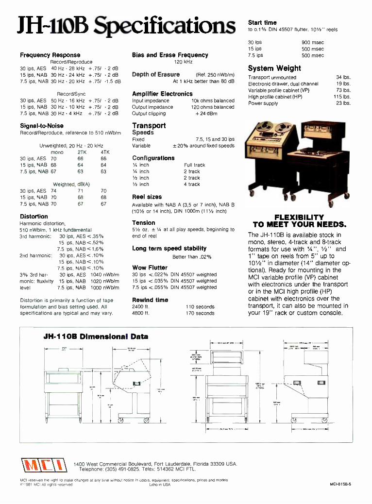
JH41OB Specifications Start time to 0.1 % DIN 45507 flutter, 101/2" reels
Frequency Response Record /Reproduce
30 ips, AES 40 Hz - 28 kHz +.75/ 15 ips, NAB 30 Hz - 24 kHz +.75/ 7.5 ips, NAB 30 Hz - 20 kHz +.75/
Record /Sync 30 ips, AES 50 Hz - 16 kHz +.75/ 15 ips, NAB 30 Hz - 10 kHz +.75/ 7.5 ips, NAB 30 Hz - 4 kHz +.75/
- 2 d -2dB -1.5 dB
- 2 d - 2 d
- 2 d
Bias and Erase Frequency 120 kHz
Depth of Erasure (Ref. 250 nWb /m) At 1 kHz better than 80 dB
Amplifier Electronics Input impedance 10k ohms balanced Output impedance 120 ohms balanced Output clipping +24 dBm
30 fps 900 msec 15 ips 500 msec 7.5 ips 500 msec
System Weight Transport unmounted Electronic drawer, dual channel Variable profile cabinet (VP)
High profile cabinet (HP)
Power supply
34 lbs.
19 lbs.
73 lbs. 115 lbs.
23 lbs.
Signal -to-Noise Record /Reproduce, reference to 510 nWb /m
Unweighted, 20 Hz - 20 kHz mono 2TK 4TK
Transport Speeds Fixed 7.5, 15 and 30 fps
Variable ± 20% around fixed speeds
30 ips, AES 70 66 66 Configurations 15 ips, NAB 68 64 64 '/4 inch Full track 7.5 ips, NAB 67 63 63 1/4 inch 2 track
'/2 inch 2 track Weighted, dB(A) '/2 inch 4 track
30 ips, AES 74 71 70
15 fps, NAB 70 68 68 Reel sizes 7.5 ips, NAB 70 67 67 Available with NAB A (3,5 or 7 inch), NAB B
(101/2 or 14 inch), DIN 1000m (111/2 inch) Distortion Harmonic distortion, 510 nWb /m, 1 kHz fundamental 3rd harmonic: 30 ips, AES <.35%
15 ips, NAB <.52% 7.5 ips, NAB <1.6°/0
2nd harmonic: 30 ips, AES <.10% 15 ips, NAB <.10%
7.5 ips, NAB <.10% 30/0 3rd har- 30 ips, AES 1040 nWb /m monic: fluxivity 15 fps, NAB 1020 nWb /m level 7.5 ips, NAB 1000 nWb /m
Distortion is primarily a function of tape formulation and bias setting used. All specifications are typical and may vary.
Tension 51/2 oz. ± 1/4 at all play speeds, beginning to
end of reel
Long term speed stability Better than .02%o
Wow Flutter 30 ips <.022% DIN 45507 weighted 15 ips <.035% DIN 45507 weighted 7.5 ips <.055% DIN 45507 weighted
Rewind time 2400 ft. 4800 ft.
110 seconds 170 seconds
FLEXIBILITY TO MEET YOUR NEEDS.
The JH -110B is available stock in mono, stereo, 4 -track and 8 -track formats for use with Y < ", 1/2" and 1" tape on reels from 5" up to 10'/2" in diameter (14" diameter op- tional). Ready for mounting in the MCI variable profile (VP) cabinet with electronics under the transport or in the MCI high profile (HP) cabinet with electronics over the transport, it can also be mounted in your 19" rack or custom console.
JH -11OB Dimensional Data
I I
If MP.
.21 ow
1
-
-, \u\i\\ 1400 West Commercial Boulevard, Fort Lauderdale, Florida 33309 USA.
Telephone: (305) 491 -0825. Telex: 514362 MCI FTL.
MCI reserves the right to make changes at any time without notice in colors. equipment. specifications. prices and models. 1981 MCI All rights reserved Litho in USA MCI- 81Sa -5

Special Report MARK B. WALDSTEIN
Broadcast Manufacturers Survey
The MCI Broadcast Audio Production Package. Console: JH- 618- 10- 60 /VU; Tape Recorder; JH- 110C -8 with autolocator /remote control, JH- 110B -2 -HP.
- How important is the hroadcast market to you? - How much of your business is derived from this source? -Is the broadcast market looking for specific broadcast
equipment or are they simply buying recording hardware and adopting it to meet their needs? - What are your liuure broadcast marketing plans!
T, s1 w'P.RL I HE QU[S1IONS we put to 23 equipment manufacturers in an attempt to get a feel for what is
going on in the broadcast industry. As could be ex- pected, the answers varied, both in terms of opinions
and length. Whereas some companies were quite taciturn in
their responses, others severely tested the (admittedly poor) dictation skills of our staff.
Mark 14aldsiein is the associate editor of db magazine. .- Circle /5 on Reader Service Card
ITS IMPORTANT
The one question to which the large majority of the manu- facturers' answers seemed to be in agreement was the one pertaining to how important the broadcast market was. There, the operative word was "Important! ": with variations ranging from "becoming more important," to "increasing in impor- tance," to the ever -popular "very important "; all the way up
CD

0
The ITC Series 99 Recorder; Reproducer.
to a vociferous "extremely important." Only two of the companies we contacted did not consider the broadcast market to be particularly important to them, while one other company described themselves as "just getting into the market."
in responding to our second question on actual percentages. answers varied from "none to speak of." to 100 percent. with the most popular answer being in the 40-60 percent range.
WHAT DO THEY WANT? Perhaps the most interesting answers we got were in response
to our question dealing with what the broadcast market was looking for. Not surprisingly, the answers given seemed to be somewhat related to the amount of emphasis the individual
companies give to the broadcast market. For example. one company. for which the broadcast market makes up only l0 percent of their business, felt that the broadcasters were buying recording equipment. while two other companies, for whom the broadcast market makes up 50 and 85 percent of their business, felt that broadcasters were buying products specifi- cally designed for them.
In terms of numbers. 13 of the companies we contacted felt that broadcasters were looking for product designed for them. four that they were buying the recording equipment. and six responded that it was a little of both.
Despite these disparate numbers, there did seem to be a few common threads throughout the answers that we received.
The Harrison PP -1 Post Production Mixing Console.

University Microfilms International Please send additional information for _
(name of publication)
Name
Institution
Street
City
State Zip
300 North Zeeb Road 30 -32 Mortimer Street Dept. P.R. Dept. P.R. Ann Arbor, Mi. 48106 London WIN 7RA U.S.A. England

N
The EMT 266 Transient Limiter for FM broadcast transmission.
Broadcast Audio's System 20 Audio Console.
Most of the manufacturers who answered a little of both felt that, as far as broadcast production goes, many broad- casters are willing to buy the recording hardware that is
already out there. This was generally conceded to be the case even by many of the manufacturers who believed the broad- casters wanted their own product. The main reasons for this appear to be a lack of true broadcast product available and even more importantly, the question of cost -effectiveness.
In other words, the broadcast market, with its own specific needs, is looking for and wants, product that is not only geared to them, but that is also cost -effective. And, until they find that combination, they (small stations in particular) will continue to buy the recording product, at least for production use.
1 1 1 -
111 111 II 111
The Tascam Series 32 2- channel Recorder.
The EMT 948 Broadcast Turntable.
One tact that emerged from this survey that appears perfectly clear (to borrow a phrase) is that the broadcast market is a
strong market that is still growing. And, as could be expected, this situation has been duly noted by the manufacturers we contacted. More and more broadcast products are being developed, with an eye towards both the high -powered stations and networks and the small -scale station as well.
WHAT'S AHEAD For example. Sphere has on its drawing board a low -cost
board for broadcasters, while Orban is introducing their 422A and 424A Studio OPTIMOD. designed for broadcast production studios, at the upcoming NAB Convention.
The Studer 269 Portable Broacast Mixing Console.

The Auditronics 200 Series Stereo On -Air Console.
At Broadcast Audio, the System 20 Console, which has already been purchased by Group W, Viacom, and CBS in San Francisco. is helping to move them into the "big time." Yet, they are quick to point out that they have by no means deserted the small stations.
At Neve (who began delivering consoles to CBS -TV City in Hollywood in 1975), deliveries of eight large audio consoles have recently been made to CBS in New York, while they also have been busy designing their 5100 range of consoles for TV stations and their 5300 Series for radio broadcasters.
Over at SSL, 18 of their 4000E Series Master Studio Systems have recently been sold. They are also introducing two new products at the NAB. The SSL Real -Time System, according to the manufacturer, is the first console automation package designed to bring full mixing computer assistance to live large -scale radio and TV production, while their multi -terminal hard -disk -based broadcast production scheduling system coordinates and simplifies scheduling of operating personnel, talent, in -house and outside facilities and equipment.
As Otani sees it, the key to the broadcast market is to make producers more productive. Therefore, Otari's new broadcast products will be geared towards making products that help producers cut down on the time it takes to do their job.
Auditronics, with one eye towards stereo TV, is looking to get into the video market, while Harrison. also looking at the TV market, is introducing their TV3 Console at NAB, a
Neve's new 5322 On -Air Stereo Broadcast Production Console.
TV audio production console with features to support up to 24 tracks or more. Harrison will also introduce a high- resolu- tion graphic metering system designated the DS -I.
Also being introduced at the NAB is Studer's new broadcast recorder -the A810. It is laid out in floppy disk, based on SMPTE time -code.
3M, which has merged with ITC to form (imaginatively enough) ITC /3M, has developed for broadcasters an improved player/ recorder and cartridge system which is about to be introduced.
MCI (now, MCI /Sony) has an audio production package upcoming at NAB, while their J H -800, a small general purpose audio console, is out and doing well.
Teac reported that their Tascam Series is being advertised in strictly broadcast magazines, and that many of their new products are broadcast oriented, with greater emphasis placed on systems; e.g. a mixer along with a mastering deck.
From Quad -Eight comes the Ventura II, a 28 -input record- ing -type console addressed to meet the needs of the video sweetening market.
An interesting piece of news comes from Tweed. It seems that they have developed broadcast equipment that is totally remote -controlled, and it is now being used by Capitol Radio in London, the largest radio station in London.
Other companies, while not as specific as the ones mentioned above, made it clear that the broadcast market is of interest to them, and even the companies that didn't consider it an important part of their business presently, had plans for either entering the market or increasing their output to meet the industry's needs.
Not too long ago, the "pro" audio industry ignored broad- casters and vice versa. With the increased awareness in audio quality, broadcasters are becoming more demanding in their audio requirements, and the audio industry is beginning to meet the demands of this lucrative industry.
WE'LL GIVE YOU SOUND AS CLASSIC
AS THE MUSIC.
Imagine a new broadcast cartridge that delivers musical sound like reel -to -reel. Sound impossible? Listen for yourself at BOOTH 3133 of the NAB Show.
Magnetic A/V Products Division 3M 3M hears you.
Circle 28 on Reader Servire Card
W

JOHN M. WORAM
Broadcasting and Recording in Ecuador Join our own John Woram as he takes us on a trip through some of the recording studios and radio stations of that well -known tourist trap- Ecuador.
',/yfl Ilmm
WHEN THE AMERICAN traveller thinks "far away," it usually means somewhere on the other side of the globe, or at least well on the way there. Thus, for the New Yorker, Tahiti qualifies, San Francisco
v John Woram is the editor of db magazine.
certainly doesn't. Everyone goes to San Francisco (or plans to) while hardly anyone makes it to Tahiti (although we all dream).
What about Ecuador? To which, many reply, "What about where ?" Those of us who stayed awake during high school geography class may dimly remember that Ecuador was in South America, and may be there still for all we know. Now, if only we could recall where South America is....

Figure 1. Two of Clarence Moore's early efforts: a 1950s- vintage mono tape recorder (A), and a somewhat -later two- channel machine (B) with built -in 30 -watt stereo amplifier.
NOW YOU CAN KEEP IT FROM
SOUNDING FLAT.
Andy's Tire Service 30 Sec.
We can show you a new broadcast ca~ brightest, fullest sound ever Just stop of the NAB Show
Magnetic A V Products Division 3M
ige with the BOOTH 3133
3M hears you
3M Circle 28 mi Reader .ervice Curd

Figure 2. The view from Quito. In this great- circle map, most of the world is downhill and just across the water from the HCJB transmitters.

(A) Figure 3. At the HCJB compound in Quito, consoles range from older rotary -knob boards (A) to a small 10 -in/ 2 -out Neve desk (B).
Unfortunately, most of us have managed to get through life ignoring the place. and although we've probably heard about the Amazon and the Andes. they may as well be on the dark side of the moon. Obviously. they qualify as "far away."
Not quite. Geographically, the Ecuadorian Andes and the headwaters of the Amazon are about as far removed from New York as is the Golden Gate Bridge. Culturally and spiritually, the distance is far greater. Scarcely 25 years ago. Ecuador's fierce Auca Indians still had the nasty habit of routinely dispatching visitors who came in faith to lead them into the 20th century. Just last year. a border skirmish with neighboring Peru was prolonged because authorities could not penetrate the jungle to let the troops know about the cease -fire agreement. And all this within the same time zone as the Big Apple!
By a long and happy set of circumstances. your reporter has made several trips to Ecuador, and on the most recent one was able to look in on the local broadcasting and recording scene there. Since this report appears in our Broadcast Audio issue. let's begin with a visit to the legendary I b_ de /ay- Andes: HCJB Radio.
Our story really begins some fifty years ago. when two American missionaries persuaded the government of Ecuador to let them set up a little radio station atop a mountain near the capitol city of Quito. Clarence Jones and Reuben Larson began broadcasting un Christmas day. 193E Thus. HCJB Radio was horn. although fcss may have been witness to the birth. At the time. there were six radios in Ecuador, and perhaps half of these were out -of -range of the 250 -watt transmitter.
Nesertheless, HC.IB was the most powerful missionary radio yuice un earth. I t was also the only one. By 1982. the station had long since lost its claim to exclusis ity. although its most - powertul title still holds. For today. HC.IB broadcasts over a
500M00 watt transmitter. Although there may be a handful of other such transmitters in operation around the world. HCJB stallcrs don't know of any that are larger.
In addition to its primary purpose of providing a missionary radio soke. the HCJB presence has been felt in the secular world as well. Some years after the birth of the station, a young engineer named Clarence Moore joined the growing HCJB staff. His contributions to the broadcast industry were many. including a voltage -dependent field- winding coil and a cubical quad antenna design. Moore returned to the United States in 1947 to develop a rugged tape recorder to meet the demands of the missionary broadcasting sers ice.
liven today, the HCJB environment is tough on audio hard- ware. At 9500 feet above sea level, the air is crisp and clean - there just isn't very much of it. The rarified atmosphere encourages arcing and inhibits cooling of electronic devices. As a general rule, equipment needs a power rating about thirty
(B)
percent above what's required at sea level. Capstan motors constantly overheat, and the HCJB staff has had to replace many of them with cooler -running mechanisms.
Apparently, Moore's early products met the need of a lot of other people besides his missionary colleagues. For today, there are few recording studios that have not used some of the products of the company he founded: Crown International. Inc. The company's letterhead still bears the message: "By All Means Today for Souls Tomorrow " -a quiet reminder of its late founder's faith.
WE'VE PUTAN END TO STALE SOUNDING
JINGLES.
We've developed a new cartridge with sound so bright and fresh it'd give new dimension to your music program- ming. See what we mean at BOOTH 3133 of the NAB Show.
Magnetic A V Products Division 3M 3M hears you..
3M Circle 28 on Reader Service Card

co
Figure 4. Our editor, trying to look knowledgeable about the intricacies of HCJB's hydro- electric plant.
While HCJB grew by several orders of magnitude, Crown grew to occupy a similar niche within the pró audio industry. The Crown tape recorder was soon joined (and eventually eclipsed) by a line of rugged power amplifiers, and more recently, microphones and test equipment.
By the mid- 1970s, HCJB's engineering staff in Quito had completed their initial engineering- concept plans for a new 500 kW transmitter. And by now, Crown International had grown considerably. and Clarence Moore offered the use of his facilities for the construction and testing of the transmitter.
On February 18. 1981, the official dedication of the transmitter took place at the transmission site in Pifo, some 20 miles from Quito.
If HCJB had to buy its electricity in the US, it would cost about $80 per hour to stay on the air. In Ecuador, the cost is
about $10 per hour, since the station is able to generate most of its own power. HCJB engineers credit a series of "divine coincidences" for this. For one, the transmitter site turns out to be comfortably close to the headwaters of the Amazon, which begin in the surrounding mountains. The nearby Rio Papallacta conveniently drops almost 500 feet in a series of beautiful waterfalls. It's a splendid place for a hydro -electric plant.
To make a very long story short, by coincidence the mission was able to find a turbine, originally installed in Seattle in 1910, that could be purchased for $2,500 -half of its scrap value. By another coincidence, the turbine design exactly matched the conditions at the river site. And so today, the Papallacto hydro- electric plant turns out 1,800,000 watts. A four -wire power line traverses the 20 miles to Pifo, passing over the Continental Divide at altitudes of up to 14.000 feet.
The HCJ B production studios are located on a two -city block compound in Quito. The facilities are extensive, yet sparsely furnished. There are five studios and eleven control rooms. The two largest are equipped for stereo; all else is mono. Audio consoles range from vintage RCAs with rotary knobs to a IO
in; 2 out Neve in the main studio. Tape recorders include early Crown and Ampex models, and a goodly number of ITC and Revox machines.
Most programming is taped for future transmission. At HCJB, the broadcasting "follows the sun," with programs reaching targeted areas in the early morning and evening hours. A maximum of six programs may be transmitted simulta- neously, though three or four is the more -usual number. The station beams at least one hour's worth of programming into each of the eleven times zones of the Soviet Union, and also
covers North America, Europe and Japan. While Soviet listener response is difficult to measure, the station has little doubt about its reception elsewhere. It is not unusual to receive several thousand letters per month from Japan. and HCJB enjoys the distinction of being the only Christian station to receive consistent mention in shortwave popularity polls. In fact, it regularly places in the list of "top ten" stations preferred by shortwave listeners around the globe.
Closer to home, the HCJB accent is of course Spanish, and also Quechua: the language of about 4,000,000 South American Indians. Resident technic() de sonido Al McElheran reports that Quechua recording sessions may run to 8 or more hours at a time, since the Indians have had to travel to Quito from so far away. In Ecuador, "far away" may mean 50 miles or so. Further distances- especially eastward -are almost unthinkable.
Looking ahead, McElheran hopes that eventually he can upgrade at least one of his studios for multi -track production work. With recording going on in 14 languages plus 17 Quechua dialects for a total of 70 program hours a day, he needs all the help he can get.
In any language, the typical (music) recording session may consist of a native -born singer, backed by a chorus of local talent who may or may not be comfortable in the language of the moment. It's a situation in which a few extra tracks for "fixing it in the mix" would go a long, long way. A four -track machine would be a great blessing, and as for a completely - equipped multi -track studio, that would positively be a gift from heaven. Which, in Quito. is not very far away at all.
COMING DOWN TO EARTH From Quito, high in the Andes, to Guayaquil on Ecuador's
Pacific coast, is a distance of not even 200 miles, as the condor flies. On the ground, make that 300 (it feels more like 3000) miles of hair -raising travel on one of the engineering marvels of the century: the spectacular "Devil's Nose Railway." As the railway's single narrow -gauge car plummets two miles downhill, it passes more than 300 bridges, tunnels and bends, with a liberal sprinkling of switchbacks thrown in for good measure. Some 12 hours later (if all goes well), the slightly - dazed traveller is deposited in Duran, just across the Guayas River from Guayaquil.
Guayaquil looks like -and is -a steamy tropical seaport. Quito escapes this traditional equatorial climate by virtue of its position high in the Andes. It's one of the few places on earth where, if you like, you can freeze to death on the equator.
No one ever froze to death in Guayaquil. For your standard gringo tourist, a day -long visit in February is like spending a
week locked in the steam room at Jack LaLanne's. Most visitors (including yours truly) pass through Guayaquil as quickly as
Figure 5. The main transmitter room at Pilo.

possible on their way between Quito and Ecuador's world - famous Galapagos Islands. Some never even leave the airport.
Summer in Guayaquil is quite another matter, as your reporter was to find out last August when he participated in El Curso Latinoantericano sobre Tecnicas de Grabación or, A Latin -American Course in Recording Techniques. This week- long seminar was sponsored by MCI and took place at the Fahrica Ecuatoriana de Discos S.A.: that is, the Fediscos Recording Studios. (The weather was delightful.)
What sort of studio does one find in a sometimes -steamy tropical seaport? What else -an automated 24 -track installation in a room designed by Tom Hidley's Eastlake Audio.
Fediscos' gerente general is Senor Bronislaw Wierdak Feraud. or "Broni," who gave us a capsule history of the company.
" Fediscos started out as a record pressing plant in 1966. It began with three old presses and four employees, and the operation was limited to pressing only. Today, we have a
complete manufacturing facility which includes a 24 -track recording studio, disc -cutting rooms, compound mixing, galvanic department, record presses: and a cassette duplicating system. We also have a printing shop, a radio station, and do our own injection molding, among other things. Our work force now numbers 200 people.
"So far, our largest project has been the construction and installation of our 24 -track recording studio. It took about 21 years to complete, and plenty of difficulties were encountered along the way.
"Eastlake provided the design, and sent a foreman here to supervise the work. Other labor was locally provided.
"Our troubles began when we couldn't find soft wood locally that was both dry and straight. We had assumed that Ecuador, being an important producer and exporter of fine woods, could provide any kind of wood we needed. The reality was another thing. Our solution was to import the wood, but we were blocked at first by an Ecuadorian trade law which forbids such imports. To get the proper import license took seven months of paperwork.
Figure 6. The Central Control Room, from which up to six programs may be sent out simultaneously.
OUR NEW CART CAN GIVE IT MORE LIFE.
Rosehill Funeral Home 60 Sec.
Stop by BOOTH 3133 of the NAB Show and we'll show you a new broadcast cartridge witn sound so good, it'll bring any commercial alive.
Magnetic A/V Products Division /3M 3M hears you
3M Circle 28 on Reader Service Card

Figure 7. The Eastlake- designed studio and control room at the Fediscos Recording Studio in Guayaquil, Ecuador.
"Once the wood arrived, construction work went smoothly. although getting other material was often very difficult. Many of us had to travel back and forth to the United States in search of the needed supplies.
"The electronic package was provided by Estemac Peruana S.A., a manufacturers' representative with offices in Lima. Sao Paulo and Hamburg. It included an MCI J H-I 14 -24 recorder with AutoLocator, two 1/4-inch machines. an MCI J H-636-28
c console with J H -50g 600 automation, Dolby noise reduction on all tracks, an Eastlake monitoring system, UREI LA-4
compressors and 527A graphic equalizers, four (!) Eventide 2830 Omnipressors, an H910 Harmonizer, and all the necessary microphones, earphones and test equipment.
"For Fediscos, it was a very big move. In one jump, we went from quarter -inch to 24 -track recording. Our technology and multi -track recording know -how were very limited, so we brought in recording engineers and technicians from the United States and other countries to help train our staff. We also presented some locally- designed audio courses. Over the years. our recordings have been progressing in quality and talent. and

VILIALFJNbl1A
Imlli IIIÌIIIIIIII1111O111Wlllll nnmlumnunun
m /,1111b t p 11m-r nulllluono u,j
1'1_ls-lR' C 11111.:PC'::: C If1111119I1II1'IlII1111Y17:-PI'IJ73`71 ' ,IrIIP ahG\a\\,...
- 41g. . ' /ry
lll` 1140 I Ili III11
=le/{._/\' ,/ dC 1 /I,c \1\ i III II111r11 I11r11
lA 11 11111 YII Il / \ _r' tr\ % \-/. 1 /d r¡ ,`\,
u 1 `t\ 1(1_il\.1z\
at the present time we are producing records of international quality.
"In August, 1981, MCI selected Fediscos for its first Latin - American seminar on recording and maintenance techniques. MCI Field Service Engineer Gregg Lamping and db Editor John Woram were the instructors. Recording engineers from Venezuela, Colombia. Ecuador. Peru. Chile. Brazil and Bolivia participated. It was a great success, and marks the beginning of a series of such seminars to be held throughout Latin America.
"The construction of a multi -track studio in an under- developed country involves all the normal planning that is
required in any industrialized land. plus a lot more. If any db readers plan to embark on such a task. there are three important steps to follow: I. Think it over. 2. Re -think it over. 3. Don't do it.
"However, if you are determined to be one of those heroes who do not want to follow step 3, let me offer some advice: make sure that you are able to obtain all building materials locally. If you must import anything, make sure you can do so legally. (Visiting consultants, please note --Ed.) Next. get all your materials and tools to do the job down to the last nail and staple. Then, and only then, begin construction.
"Check local laws and tariffs very carefully. Local labor may be a problem, and at the least an experienced foreman should be contracted. And make sure he is able to cope with the local conditions and customs. Once the studio is constructed and the equipment installed, appropriate training of your staff should follow.
"The making of a recording studio the way we did it is a story that should not be repeated. and we will be only too glad to guide anybody in Latin America who wants to follow our example, but not our mistakes.
"Having completed our recording studio, Fediscos is now expanding its operations to include cassette tape slitting, and cassette molding and assembly. We look forward to a bright
future as a source of industry, work, talent and culture."
LOOKING TO THE FUTURE What does tomorrow hold for the fledgling recording in-
dustry in Ecuador? For the moment, the prospects are not promising. There are but a handful of studios in the entire na- tion, and none to rival the premier position of Fediscos. In Quito, Sonox Grabaciones is doing some imaginative work, but is held back by the difficulty in getting equipment.
Would -be suppliers of recording hardware are advised to proceed with caution, for doing business in Ecuador is not easy -in fact, it's almost impossible. Except for its natural beauty, the country is not wealthy. To protect its balance of payments, the Ecuadorian authorities impose staggering tariffs on a va- riety of imported products. Some are understandable; others seem capricious.
The Ecuadorian citizen who resists buying an imported car will wind up spending his money on locally -provided trans- portation. thus assuring jobs and bolstering the country's economy.
On the other hand, Ecuador's rich musical heritage is being short- changed. The bureaucracy imposes a de -facto embargo on electronic equipment by imposing tariffs that prevent the development of a local recording industry. As a result. musi- cians are forced to leave home in order to record their music.
If they can afford to do so, they wind up spending their money in foreign recording studios. and the Ecuadorian economy is deprived of one more industry that could go a long way towards improving, through entertainment, the quality of life there. it's ironic that the wound is self -inflicted.
Hopefully, the recording industry of Ecuador may look for- ward to some enlightened changes in future legislation that will help to stimulate its growth. For as Charles Darwin realized after visiting Ecuador's Galapagos Islands, things do indeed change; it just takes a little time. vt

NIGEL BRANWELL
Selective Limiting Author Branwell offers some expansion on one aspect of multi -band limiting -or, Dynamic Processing: Part III.
Ii
The Transdynamic Tri -Band Processor
(12) Calibrate System using built -in Pink Noise generator or programme audio
(13) Monitor L 8 R or sum on Modulation Meter (14) Modulation Meter (PPM Ballistics) will monitor
unprocessed and processed audio (15) Gain reduction in Master Limiter (16) Indicates 6 or 12dB /octave crossover selected (17) Indicates processed /unprocessed signal at main
output (18) Indicates DIR -MIX (Direct /Mix compression)
switched IN /OUT (19) Return levels from Compressor /Limiter
(1) Channel Master Input (2) LF /MF Crossover Variable (3) MF /HF Crossover Variable (4) Limiter Threshold (5) Channel Master Output (6) Calibrates Modulation Meter to following system (7) Indicates Clipper Circuit switched IN /OUT (8) Clip indication (9) System Master IN /OUT
(10) Stereo /Dual Mono (11) FM Pre -emphasis selectable
SELECTIVE LIMITING IS THE action of limiting (or momentarily attenuating) any previously -bandsplit sections of an audio signal where energy levels exceed the established threshold levels. This process results in
higher cutting levels in disc mastering /cutting, or higher transmission levels in broadcasting, without apparently alter-
Nigel Branwell is vice president of Audio + Design V) Recording, Inc.
ing the dynamic range of the original program. Normally, the threshold levels from multi -band limiters are
set to the same level, although these relationships may be adjusted to suit any particular overload characteristics in the following chain (for example, pre -emphasis or tape saturation characteristics). When output levels are the same in each band, it will be found that on wide dynamic orchestral music the low - frequency energy band will often lead other bands by as much as
4 to 6 dB in peak level. If processed by a single wide -band limiter, such an inbalance could cause modulation effects by

depressing the mid -band and high- frequency section, noticeably flattening the presence and high- frequency content. The effect might be so great that it would normally be considered impractical to significantly limit such programs.
EQUALIZATION IN DYNAMIC FORM By selectively processing the low -frequency section in
particular, it will be found possible to increase program level by 4 to 6 dB in average modulation level at the expense of a periodic and momentary attenuation of peak low frequencies. This is equalization in dynamic form. Without such processing, the entire program would have to be transmitted or transferred some 6 dB lower. In disc cutting, where higher average levels are important to reduce subsequent pressing problems, even a fixed attenuation of the low frequencies might be used, in order to increase average level or playing time.
On light orchestral or pop programming, the mid -frequency section is likely to equal the low frequencies in peak energy, though often not at the same time. On average, it will be 2 to 3 dB lower, but on vocals it can equal, or even momentarily exceed, the low -frequency band. Under such program conditions, an additional modulation influence is added to complicate wide -band limiting. But since a faster release time can be used, the effect may not be considered as severe as high - frequency modulation by low -frequency program.
On big -band type programs with strong brass sections. the energy spectrum will be more evenly spread into the high - frequency band, but it will still be noted that peaks in each section are random, and by no means always synchronous. Even for such program content, a tri -band limiter with correctly adjusted crossover points can significantly increase average level in excess of 6 dB. without apparently altering the dynamic range of the program. Because the average level is higher, it sounds louder for the same peak level. Thus, although the average low level program is increased, the average peak level is
also. The dynamic range will be subjectively similar, but a gain of some 6 dB will have been made through the transmission system.
LIMITING Such changes as occur in selective limiting are momentary
modifications to peak level response, with the spectral balance being briefly altered. Higher levels are not achieved at the expense of a fixed equalization that degrades the entire duration of the program. There is, rather. a momentary variation in response that lasts for less than 5 percent of program duration on orchestral material. On pop selections, the duration of the modification could be longer, and will depend on the amount of limiting action established. But changes of frequency balance at peak level are undetectable to the listener, whereas deficiencies in disc noise or in the transmission channel are constantly present. Such restricted modification must be considered greatly advantageous.
Even on program material where the energy spread is more even throughout the bandwidth, limiting action in a tri -band system will be subtle and free from band -related modulation effects.
In order to handle specific problems such as obtaining longer playing times or coping with high- frequency saturation or overload, the appropriate band's threshold can be lowered with respect to the other bands. In the limiter section, the built -in gain makeup is usually adjusted to maintain a flat response below threshold (each band has equal gain below threshold). Therefore, the effect of lowering a threshold would be to increase the limiting action in that band, thus modifying the program for a greater proportion of its duration. The ratio selected in the processor would normally be tight (5:1 to 20:1), in order to minimize attenuation effects to the top few decibels of the signal.
When selectively attenuating a high- frequency signal in particular (that is, when followed by pre -emphasis), care should be taken not to overdo the high- frequency attenuation more than is absolutely necessary. In the case of Audio + Design's
Transdynamic system, as a final protection, pre -emphasis can be switched into the master limiter and clipper combination. Crossover points should be adjusted to be comparable to the pre -emphasis curve used in subsequent equipment (or tape saturation curve).
Selective limiting can involve momentary gain reduction in any of the three bands; action is likely to be random, being completely program- dependent. The system response is adjusted on /v when necessary above the threshold settings. Below the threshold, a flat response prevails.
Tri -band compression can be used with selective limiting and will normally be established so that at peak level the same amount of gain reduction occurs on all sections. giving a flat response at peak level. Dependent on release time and slopes used in each section, the response down to threshold can be dynamically controlled. An evenly- spread amount of gain change gives a flat response, with variations leading to dynamic changes and possible enhancement effects. Below threshold, the response will normally be flat with equal gain established in each processor.
An increasing amount of "new" music originating in Great Britain has been processed in this way, and the results are obvious in terms of longer disc playing times and /or hotter discs, while the dynamic integrity remains unchanged.
In the United States, radio and television stations are employing the techniques of selective limiting with excellent results: while achieving competitive loudness, the program material remains apparently unaltered.
Nigel Branwe// two -part "Dynamic Processing" appeared in the July and September. 198/ issues of db. The author welcomes questions, comments and further discussion on the subject.
S T PRECISION
Oras
MAGNETIC TEST TAPES
STANDARD TAPE LABORATORY, INC. 26120 EDEN LANDING RUAI) 5. HAYWARD. CALIFORNIA 94545 I4I5I 781.3546
Circle 26 on Reader Service Card

GARRY MARGOLIS
Broadcast Audio A Primer for the Recording Engineer The following article on broadcast audio is written with an eye towards the recording engineer.
BL-40 MODUUMITER
Yq a+1M 1.1 V1
iSrt
* ..
^ a -i_
i
The UREI BL -40 Modulimiter combines the functions of RMS and peak limiting with automatic polarity inversion and 125 percent positive modulation.
N BROADCAST AUDIO, the state of the art is quite different from the state of the art in the recording of discs and tapes. Each medium has its unique requirements, and the unwary producer or recording engineer can create severe
problems if he or she is not aware of the limitations of broadcast audio.
Some manufacturers of recording studio equipment have
Gary Margolis is director of sales at URE /- United n Recording Electronics Industries.
also not understood these limitations, and their products have not been well accepted in the broadcast market. For example, there is no reason for an on -air broadcast console to 'have the superb technical specifications now required for recording con- soles. On the other hand, the broadcaster's equipment must be even more reliable than the recording studio's -an equipment failure at a recording studio can be quite expensive in terms of lost time and income, but a failure at a broadcast station can result in serious legal and financial problems because of gov- ernment enforcement.

We have been involved with both recording and broadcast audio for many years and have seen and heard the unfortunate results of these two communities not understanding each other's requirements and constraints. This article is intended for the recording engineer without extensive broadcast audio knowledge. It will address the limitations of broadcast audio and suggest some means of alleviating some of the resulting problems.
COMMERCIAL RECORDING the finest of the audio art is expected, and usually de-
manded, by the artist,. engineer and audiophile. Limitations in recording and reproduction media are frequently viewed as barriers to creativity, and much effort is expended on over- coming them.
One of the most irksome problems, particularly for the classi- cal musician, has been the limited dynamic range available. Until the advent of digital recording, there had been no prac- tical way to capture the full 70 -80 dB (or greater) dynamic range of a symphony orchestra on a master tape, let alone to preserve it through the many steps leading to the home play- back. Popular music generally does not have the inherent dy- namic range of classical music, but the buildup of noise from multiple tracks being combined through several generations becomes thoroughly bothersome as well. Dolby, dbx, CX and other methods of noise reduction help, but do not completely solve the problem.
Available bandwith has not been as serious a problem as dynamics, particularly with the recent improvements in con- sumer phono cartridges and loudspeakers. During the past five years, the effective low frequency limit has gone from about 40 Hz to below 20 Hz, and some recordings exploit the increase with vigor (viz. Telarc's /8/2 Overture disc #10041).
The broadcaster, however, has quite a bit less bandwidth and dynamic range available than the recording engineer. There has been no fundamental improvement in broadcast audio since the introduction of FM stereo broadcasting in the early Sixties, apart from Dolby's valiant attempt to introduce noise reduction into FM radio broadcasting and the stereo and bi- lingual telecasts in Japan and West Germany.
FM RADIO BROADCASTING I he potential 60+ dB dynamic range of FM radio transmis-
sion is actually quite reasonable but is rarely encountered on the air, for several reasons. First, there is a statutory ceilng on the amount of modulation which any broadcaster can put on the air. If an FM broadcaster exceeds this limit, it may cause inter- ference with adjacent stations and distortion may be gen- erated in some receivers. Second, 20 percent of the potential modulation capacity of most FM stations is taken up by the stereo pilot signal and the SCA (Subsidiary Commu- nications Authorization) signal used for background music. If the station's transmitter and antenna are not in excellent shape, the SCA signal can create interference with the stereo subcarrier, resulting in high frequency noise. Third, some sta- tions operate on limited budgets and consequently are not able to obtain the best equipment available and keep it in the best possible shape. Fourth, most FM listeners will be using inex- pensive equipment, and many will be in automobiles, where the background noise will drown out quiet passages.
Most FM radio broadcasters utilize some form of peak limit- ing to put an absolute ceiling on their broadcast level and insure that they don't interfere with other broadcasters, and i or re- ceive a citation from the government regulators. A broadcast peak limitor must quickly respond to a rapid change in instan- taneous level with little or no overshoot. It must have a large level- control range (limiting ratio), usually 20:1 -a 20 dB change in input strength above the limiting threshold (the level where limiting begins) results in only I dB of output level increase.
Fast peak limiting can increase the average modulation level of an FM station by 6 to 10 dB, depending on the type of pro- gram material, the original dynamic range of that material,
and the skill of the station's staff. Tastefully done, this will gen- erally not be objectionable, and can make the difference be- tween usable and unlistenable reception, particularly in weak signal areas and in automobiles.
Since most classical and pre -1970 popular music, as well as normal speech, does not have a powerful high- frequency con- tent, FM transmissions have the high end of the audio spec- trum boosted, with a complementary rolloff built into the re- ceiver. This pre- emphasis and de- emphasis (75 microsecond time constant unless Dolby encoding is being used) reduces the amount of hiss encountered by the listener. The peak limiter used by the FM broadcaster will usually compensate for the effects of pre -emphasis, so that the transmitter will not be over - modulated by excessive high frequencies.
However, program material is now much richer in high fre- quency content than it was at the time when this equalization curve was chosen. Tape and disc equipment and materials have improved to the point where astounding amounts of high frequencies (cymbals, sibilance, etc.) can be recorded in the studio, transferred, and reproduced in the home. But an FM station with an ordinary peak limiter will not be able to repro- duce these highs without either significantly reducing the over- all signal level or overmodulating. Some limiters designed for FM broadcasting break up the frequency spectrum into sepa- rate bands and limit them separately (allowing for pre- empha- sis), thereby minimizing the level pumping which can result from large amounts of highs forcing a broad -band limiter into reducing the level of the entire spectrum.
Additionally, many stations wish to keep their dynamic range even more restricted -they may be specializing in music in- tended for background listening; or their targeted audience may be primarily using portable or automobile radios. These stations will use a compressor in addition to a limiter, to keep the overall level within an even -narrower range.
While a limiter acts quickly and drastically on the dynamics, trying to follow the peaks, a compressor generally acts slowly and gently, following the arms or approximate average signal level. The compression ratios are generally in the 2:I to 4:1 range, and short -term peaks are allowed to go through without modification -the peak limiter will follow the compressor and take care of peaks which could create overmodulation. The compressor's threshold is set at a much lower level than the limiter's, taking care not to set it so low that the background noise becomes too noticeable.
Some broadcast signal processors include both compressors and limiters in the same package, with two identical interlinked channels to keep the stereo image from wandering if one chan- nel needs different processing than the other.
FM broadcasters generally will restrict the audio bandwidth of their transmissions. When significant amounts of low fre- quency energy are present, the maximum midband audio level must be reduced to stay within permissible modulation limits. Cue tones for switching automatic programming equipment are in the 20 -25 Hz region and can create annoying distortion in the receiver if they leak into the transmission, so all program audio below 40 or 50 Hz is usually filtered out. High -frequency pro- gram material can beat with or override the 19 kHz stereo pilot signal, so most FM stereo stations filter out all program ma- terial above 15 kHz.
One additional factor which is built into FM broadcasts is
limited stereo separation. In the early Sixties, when stereo multiplex broadcasting was adopted, portable and automotive FM radios were rare, the audience was small, and most FM broadcasters were struggling to keep their doors open. SCA background music broadcasts helped many to survive. There were two major competing methods of broadcasting stereo while maintaining compatibility with monaural receivers. Both the Zenith -GE and Crosby systems used the familiar L + R monaural sum for the main audio channel, which is picked up by a standard monaural receiver. Both also used an out -of- phase combination of the two channels (L - R) on an inaudible subcarrier, to be added to and subtracted from the main chan- nel in a stereo receiver, obtaining separate left and right out-
tr

puts. Crosby's system had better potential stereo separation than the Zenith -GE, but could not be used simultaneously with an SCA signal. If it had been adopted, few broadcasters could have afforded to convert to stereo and, after much deliberation, the FCC chose the Zenith -GE method. Many stations quickly installed stereo equipment, listenership increased rapidly, and the powerful FM broadcast industry of today resulted.
The separation available from the Zenith -GE system was originally about the same as from a reasonable phono cartridge (about 30 dB in midband) and, as such, was not grossly objec- tionable unless extreme separation was the goal, such as the early stereo broadcast practice of putting the announcer into one channel only. Phase -locked loops have improved the sepa- ration of high -quality receivers, and careful transmitter and antenna maintenance can keep midband stereo separation in the 40 dB range, which is adequate for most purposes.
FM broadcasts , then, generally have a bandwidth of 50 Hz to 15 kHz, a dynamic range of about 30 to 40 dB, good stereo separation, and distortion which depends on how much signal processing is done as well as the quality and conditions of the rest of the station's equipment.
TELEVISION AUDIO Television audio is impressed on its carrier by FM, using the
same 75 microsecond pre -emphasis as the FM radio standard. However, its maximum modulation level is only about 40 per- cent of that used by an FM radio station (after subtracting the stereo pilot and SCA signals on the radio carrier). Conse- quently, the dynamic capability on TV is even worse than on FM radio, by 6 dB or more. But there is still more to get in the way. Most television receivers use a miniscale audio power amplfier feeding a miserable loudspeaker in an acoustically - ridiculous enclosure. If that isn't bad enough, most receivers process the audio, video and synchronizing information simul- taneously through much of their circuitry. This cost -saving technique, called "intercarrier," often results in buzz and hash leaking from the video and synchronizing signals and circuits into the audio. The average viewer doesn't have much of a chance for decent quality audio unless he or she has a TV audio tuner or VCR with good audio quality connected to home high fidelity equipment.
Television audio is almost always processed to an even greater degree than FM broadcast audio, so that the sound quality fed through the typically poor reception can be intelli- gible and as pleasant as possible. The same type of signal proc- essing is done for both media, but TV audio will typically be compressed more, and some frequency contouring may be in- troduced with an equalizer to attempt to get a hint of low -fre- quency response out of the receiver. Mixes done with home listening in minds can be problematic when used on television as backup for an artist's lip- synchronization unless the potential problems have been anticipated.
AM BROADCASTING AM radio has a statutory restriction on the amount of mod-
ulation which may be broadcast, just as FM and television broadcasts do. However, there is an important difference. FM carrier signal strength is constant and independent of the audio signal, since the frequency -and not the strength -of the car- rier is changed. Audio is impressed on an AM radio carrier by changing the strength, or amplitude, of the carrier. The carrier amplitude follows the audio waveform so that if a I kHz sine wave is broadcast, the carrier's amplitude will vary up and down 1.000 times per second. If there is no audio signal, the carrier will be radiating at its nominal authorized power (in watts) and will not vary in strength. At 100 percent modulation of a sinusoidal input, the signal will cause the carrier strength to vary from four times the nominal authorized power at the positive peaks to no power radiation at the negative peaks of the modulating sine wave.
Because the amplitude of the carrier is directly proportional to the geographical area over which the station is heard, all else being equal, AM broadcasters have a vested interest in
keeping the average modulation level of their stations as high as possible. Consequently, AM stations use a considerable amount of signal processing. Large amounts of compression and limiting are used to restrict the program level variation to only about 6 to IO dB, or even less in extreme cases.
AM broadcasters have even more reason to avoid overmod- ulation than FM broadcasters do. When an FM station over - modulates, there might be interference with adjacent channels. However, when an AM station overmodulates, it tries to go over and under the 100 percent to 0 percent modulation range. Since it is not possible to radiate less than zero percent of auth- orized power, the resulting waveforms will be clipped. Besides severely distorting the audio, this generates gobs of harmonics which will splatter all over the electromagnetic spectrum, cre- ating interference with many other broadcasts.
Since most program material is not sinusoidal and AM inter- ference is caused by negative -going overmodulation, AM broadcasters in the USA, Canada, Mexico and some other countries are permitted to radiate up to 125 percent modulation on positive -going peaks. Peak limiters designed for use in AM broadcasting may have specialized circuitry to allow this asym- metric condition to pass through, and some, such as the peak - limiting section of the UREI BL-40 Modulimeter, will sense which direction the asymmetry favors and invert the signal polarity until an envelope of opposite asymmetry is detected, at which time the polarity will again be inverted.
Multi -band signal processing has become increasingly popu- lar in AM broadcasting, with up to six or seven subdivisions of the spectrum being processed separately for maximum level. Such processors are extremely powerful tools, capable of pro- ducing good- sounding results on a variety of types of program material while dramatically increasing the average modulation level and, therefore, station coverage. If, however, these signal processors are improperly designed and/ or adjusted, they can wreak havoc with the subjective balance of the program material.
No pre- emphasis or de- emphasis is done in AM broadcast- ing, although midrange boost is commonly used to increase presence and brightness. Unlike FM and TV audio, which have complementary high- frequency equalization in the transmitter and receiver, AM broadcasts do not have a specific high -fre- quency rolloff in the receiver, but few AM receivers will repro- duce above 5 kHz. Some broadcasters can produce a fairly wide -bandwidth signal, but if they do, they will probably be wasting power on a broadcast which few will appreciate.
SOME SUGGESTIONS Many recording engineers and producers monitor their re-
cordings on small, inexpensive loudspeakers such as Aura - tones, to try to approximate the effect which will be heard when the final product is played on the air. This can work fairly well for FM and television audio simulation. However. many FM and television stations may not have multi -band limiters available and may have trouble broadcasting record- ings which have very large amounts of high frequencies, such as synthesizers, very sibilant vocals and prominent cymbals. Some restraint when mixing will save later grief.
Considering the amount of signal processing which will be
used in an AM broadcast, it may be advisable to monitor the mix through a typical AM broadcast signal processing system and a low- power. limited range AM transmitter. In- studio monitoring on a portable radio. off the air, will allow the producer and engineer to judge the mix under realistic con- ditions and better anticipate the balances and dynamics which will result after actual AM broadcast.
Since there is no standard method of AM signal processing. and much depends on the adjustment of the processor used, the results from this system of monitoring cannot precisely dupli- cate the sound broadcast by any particular station. However, there is no other way to simulate the effects of AM processing unless the engineer and producer have a great deal of experi- ence, and such monitoring may avoid serious and costly dis- appointment.

The Needle Knows Even when your ears
can't tell the difference, your VU meters can.
Which is why we test every reel of our 2" Grand Master 456 Studio Mastering Tape end -to -end and edge- to-edge. To make certain you get a rock -solid readout with virtually
no tape -induced level varia- tions from one reel of 456 to another or within a single reel.
No other brand of tape undergoes such rigorous test- ing. And as a result no other brand offers you the reliable consistency of Ampex Tape.
AMPEX Ampex Corporation One of The Sgnal Compamesls
4 out of 5 Professionals Master on Ampex Tape:
AMPEX 11
A consistency that lets you forget the tape and concen- trate on the job.
Ampex Corporation, Magnetic Tape Division 401 Broadway. Redwood City, CA 94063
(415) 367 -4463
'1981-1982 Billboard Magazine Brand Usage Survey
Circle 36 on Reader Servie

The Performance a Broadcaster Expects,
The Features and Reliability He Demands.
( N1 le IS .VI /s% 7h/iv' ./''9 i' Car,/

THE NEW OTARI MTR -10 SERIES
PRODUCTION RECORDERS
W e engineered them to be the ultimate in broadcast production. They embody the
innovative technology and the highest reliability that has made us The New Workhorse in audio production.
THE ULTIMATE IN PRODUCTION EFFICIENCY
Three speeds: 33/4, 71/2. 15 or 71/2, 15, 30 ips. Full, two and four track formats. Flexibility in cabinet choice: desk type, overbridge or rack mount for custom installation. Full servo, D.C. PLL transport governed by an on -board microprocessor -an industry first. ±20% vari -speed with ips or percentage display. Built -in, no overshoot return -to -zero with optional 10 memory/one stroke and keyboard access autolocator. Internal multi- frequency square /sine wave generator. Preset master bias switching. Electronically balanced I/O with direct -coupled, high current outputs. Automatic reel size sensing with single hand. bi- directional tape rocking. Cue control with lifter defeat and controlled wind. Dump edit and shuttle edit control. Integral, precision splicing block. Cue speaker and headphone monitoring. Direct access playback head. Modular, single card electronics with high slew -rate integrated circuits.
THE ULTIMATE IN ANALOG AUDIO
,
Dynamic Range: 75dB measured from noise floor to 3 °° THD (30 ips. =226 tape). Frequency Response: 0 VU ( +4) 35Hz- 29kHz. +1.0, -3.OdB@ 30ips.
111111111141111.wr.;e:a +ruu
Wow & Flutter: Less than 0.04 %, DIN 45507 Distortion: Less than 0.1% @ 1kHz, 250nWb /m. Maximum Output: +28 dBm. Adjustable record phase compensation. These features and more will allow
you to do your job faster while delivering every last dB of performance. It's the productive and efficient solution to the demanding new realities of the contemporary broadcast facility.
ENGINEERED TO BE EASILY SERVICED
Access to all components makes maintenance straightforward. The audio, transport, master CPU and
power supply electronics are all of modular, card frame design; the entire transport assembly is top- hinged to allow wide -open access while the deck is in operation.
ENGINEERED TO THE HIGHEST STANDARD OF RELIABILITY
world leader in t (Model ARS -10( production reco Series). With the
successfully bric the new technol
Evaluate the D
yourself by cont MTR -10 Series I
dealer. It will bec is several steps competition -aç performance, fe reliability that wi broadcasters fol
If you're real) broadcast preci logical decision
oadcast automation and compact
ers (the 5050 new MTR -10, we have
ged the gap between gy and reliability. 1TR -10 recorder for acting your authorized professional audio ome evident that Otari ahead of the ain. Audition the atures and engineered I meet the needs of all years to come. thinking of buying ion, there's only one
Reliability is paramount in Otari's approach to doing business. We've earned an enviable reputation for
quality and value that has made us the
2 Davis Drive Belmont. California 94002
(415) 592 -8311 Telex: 910- 376 -4890
1992 Ojai Corp

o
(Continued from page 6)
and the curve becomes independent of calibration as intended.
Once this is done, it can be seen that the statement he cites applies to the console operating -conditions of FIGURE 2,
which are correctly expressed in dBm. I believe that the familiar phrase I used will convey to most studio engineers that a console test -tone lineup -level of +4 dBm had been chosen for illustrative purposes, rather than +8 or + 10, the other popular console operating -levels at which VU meters are pre -calibrated to read a steady zero VU during lineup.
If an extra "m" altered the meaning here, an extra "meter" which crept into a
sentence on the second page of the article must have made some readers wonder what I was talking about. For a moment I wasn't sure myself. The con- fusion will be cleared for any it bothered if the last sentence in the first paragraph on p. 53 is amended to read, "The proba- bility that sound will generate transient voltage -peaks increases rapidly with the density of the sound -spectrum, but other- wise the relation of voltage -peaks to sound is unpredictable."
The fact is, of course, that few readers are bothered by misprints, annoying as
they may be to perfectionists such as
authors and editors. Most readers will note a typo with amusement, translate it correctly, and carry on. I sometimes wonder if there isn't a wry little imp hiding somewhere who injects them from time to time, just to temper our serious discussions with a touch of humor. Comedy relief -beneficial even when inadvertant.
JACK K. GORDON
THINKING LOGICALLY To THE EDITOR:
With all due respect to Dr. Barry Blesser's Digital Audio column (which is most welcome), a correction seems needed. Assuming that by up he means HI and by down LO (from the first drawing in the December column), the operational description, "... either switch being Down creates darkness," is incorrect. Rather, either switch being Up (HI inputs) creates light (HI output). If the second symbol was also an AND gate instead of an OR gate, then his operational description for it would be correct.
Yeah! It sure is "easy to make mis- takes," but why make simple matters complicated? Why make your readers dizzy with doors and bulbs, when most of them could follow better in terms of voltages. How much simpler can you get? The digital domain definitely has its own language which may cause anyone a spell or two, but if we only beat around the bush without getting to the straight- forward definitions, it certainly won't take long to put someone in a comatose
m state.
Trying to stay simple is fine, as long as we don't suddenly jump the gun, which happened in the last section of the article. It was never quite explained what the rules are for implementing a NAND gate out of a NOR gate, though I deduced that some kind of implied attempt was made.
To sum it up, the column felt like a
Disney movie directed by Orson Welles. Can you imagine ?!
Maybe there should be two regular columns. "Introduction to Digital Audio" and "Digital Audio World. "This last could be a forum for current practical problems, solutions and applications encountered by the professional users of digital audio.
As a last personal request, I would like to see a poll and survey of different systems being used (by their users of course) in db this year.
ISRAEL SOMMER Los Angeles, California
db replies: Fes indeed, it's sure easy to make mis-
takes. especially when wading through the semantic fine points of digital logic. Turning either switch ON (or if you like, Down. True. High. etc.) does turn on the darkness. The trouble is, most of us are used to turning on the light. But think of light /dark in the sanie terms as hot cold, north! south. forward /reverse. etc'.. and we can easily design a system that will turn either state ON (or OFF). And the switch can surely be designed to be ON when it is down. i /'that s what's required.
To implement a NAND out ofa NOR (or vice versa) just put an inverter in each of the lines, as shown in the 7400 and 7402 drawings un page 22 of Dr. Blesser's December column.
To THE EDITOR: Thank you for printing my letter in
the December issue concerning Dr. Diamond and digital recording. I was reading through some old issues of Popular Electronics recently, and noticed an editorial by Harold Rodgers. He apparently reached the same conclusion as I did, only his thoughts were in print in June. I just wanted to pass this on, because I wasn't sure how many people in the recording industry would see this article.
STEVEN J. HEBROCK
dh replies: Rodgers' comments appeared in the
June 1981 issue of Popular Electronics. As in our own April issue. Rodgers speculates that perhaps digital recording preserves the stress of the live perfirrm- ance. while analog does not. Rodgers concludes. "The vast library of existing analog recordings should prove suf- ficient for Dr. Diamond and his patients. while those of us who are foolish enough to want all the emotional qualities that great composers put into their music... are free to listen to digital, stress and all."
Special binders now available. All you regular db readers who, smartly enough, keep all your back issues, can now get our special binders to hold a whole year's worth of db magazines in neat order. No more torn -off covers, loose pages, mixed -up sequence. Twelve copies, Jan- uary to December, can be main- tained in proper order and good condition, so you can easily refer to any issue you need, any time, with no trouble.
They look great, too! Made of fine quality royal blue vinyl, with a clear plastic pocket on the spine for indexing infor- mation, they make a handsome looking addition to your pro- fessional bookshelf.
Just $7.95 each, available in North America only. (Payable in U.S. currency drawn on U.S. banks.) r
Sagamore Publishing Co., Inc. 1120 Old Country Road Plainview, NY 11803
YES! Please send db binders @ $7.95 each, plus applicable sales tax. Total amount enclosed $
Name
Company
Addre«
City
State /Zip L'

it EXPERIENCE IN AUDIO TECHNOLOGY
HP's 8903A now makes audio testing easier than ever before.
Now a single microprocessor- controlled instrument offers you the versatility of an extremely wide range of audio measurements with just a few keystrokes. Manual or HP -IB programmable, the H P 8903A Audio Analyzer is ideal for testing 20 Hz to100 kHz character- istics of stereo amplifiers, pre- and line amplifiers, tape decks, cassettes, and other high performance audio equipment.
The 8903A measures such basics as distortion, gain and frequency response,
04105 i power, AC or DC volts, and frequency; as well as more complex parameters like signal -to -noise and SINAD. It includes a sweepable low distortion audio source and drives an X -Y recorder directly. It's an automatic test system all in one box, yet is priced at only $6200!
For more information, contact your nearby HP sales office, or write to Hewlett -Packard Co., 1820 Embarcadero Road, Palo Alto, CA 94303. 'Domestic US price only.
HEWLETT P PACKARD
Circle 41 on Reader Service Card
SYSTEMS

N m
New Products & Servkes
RADIO CART
The ScotchCart Radio Broadcast Cartridge, consisting of a new continu- ous loop magnetic tape cartridge and tape formulation. helps minimize the problems present in current radio carts. A key design feature of the cart is a tape tension control arm. This arm provides and maintains tension at the tape -to- head point. An adjustble cam is built into the cartridge to compensate for changes in loop length. Concave guiding posts center the tape to make it easier for the record playback equipment to guide the tape over the heads. This results in lower phase error, more uniform out- put and cart -to -cart consistency. A play- back head shield, built into the cart, pre- vents stray radiated fields from getting to the equipment playback head. The tape cartridge performance is equivalent. at a speed of 71/2 inches per second (ips), to that of the high output tapes that are mastered at the reel -to -reel speed of 15
ips. ScotchCart cartridges will be offered in standard lengths from 40 seconds up to 91 minutes. and are compatible with existing tape cartridge hardware. 41k: 3M Circle 66 on Reader Service Card
TV AUDIO SIGNAL PROCESSOR
Derived from the OPTIMOD -FM. OPTIMOD-TV provides subtle multi - band compression. high frequency limit- ing, and effective control of peak levels and output spectrum. Its circuitry has been custom -tailored to the character- istics of typical television audio feeds. providing significant increases in trans- parency, naturalness, and consistency. OPTIMOD -TV is delivered as a stereo processor. Its built -in 15 kHz lowpass filters assure compatibility with future multiplex stereo systems, and prevent interference to the video. OPTIMOD- TV is easy to set up. yet is versatile enough to permit its sound to be cus- tomized to the exact needs of the individ- ual broadcaster. An optional Accessory Chassis houses the compression circuitry and setup controls, allowing compres- sion to occur before the STL. protecting it from overload. .N/r: Orban Price: $4.195.00 Circle 48 on Reader Service Card
OOPS!! In last month's New Products
section, reader service numbers were inadvertently left out for Klark -Teknik's stereo profanity delay. Ursa Major's digital rever- berator remote unit and Teac's floor console. If you wish information on these products. please contact: Klark -Teknik Electronics. Inc.. 262a Eastern Parkway. Farming- dale, NY 11735; Ursa Major. Inc.. Box 18. Belmont. MA 021780: Teac Corp. of America. 7733 Tele- graph Road. Montebello. CA90640.
CONSOLES
The RX -7's are completely modular consoles available with 16 to 32 inputs and 4 or 8 outputs. With the modular concept. a user can literally build the board he needs whether for recording. sound reinforcement orstage monitoring. Input modules feature 3 -band EQ. two echo and foldback sends. long travel faders. peak indicators and stereo panning. Inputs are transformer isolated. The remote power supply also provides phantom power for condenser mics. Mfr: TOA Electronics. Inc. Circle 49 on Reader Service Card
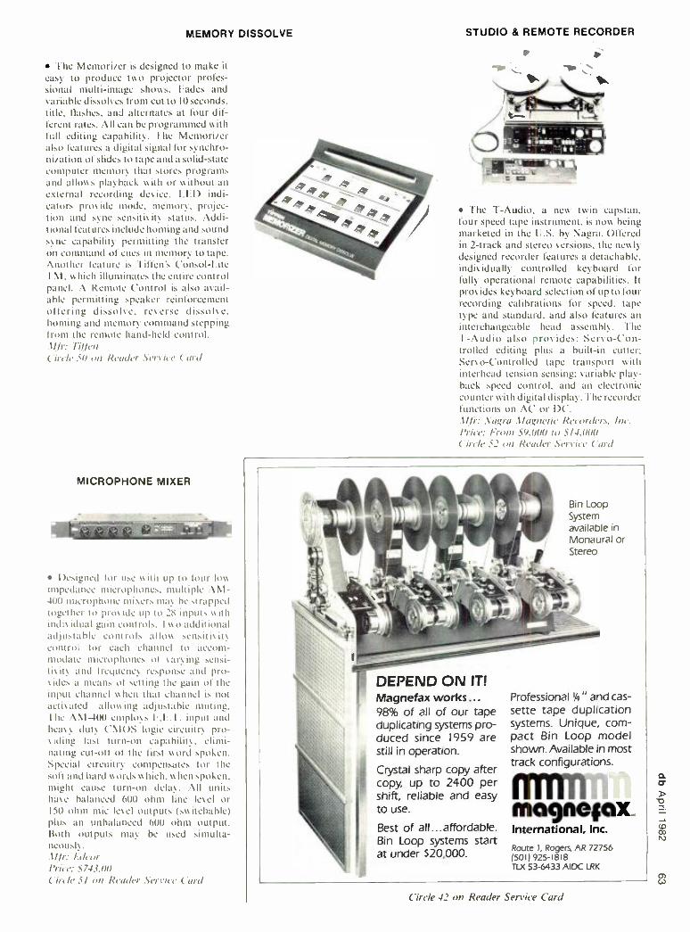
MEMORY DISSOLVE
The Memorizer is designed to make it easy to produce two projector profes- sional multi -image shows. Fades and variable dissolves from cut to 10 seconds, title. flashes, and alternates at four dif- ferent rates. All can he programmed with full editing capability. The Memorizer also features a digital signal for synchro- nization of slides to tape and a solid -state computer memory that store, programs and allows playback with or without an external recording des ice. LED indi- cators provide mode, memory, projec- tion and sync sensitivity status. Addi- tional features include homing and sound sync capability permitting the transfer on command of cues in memory to tape. Another feature is 'linen's Consol -Lite TM, which illuminates the entire control panel. A Remote Control is also avail- able permitting speaker reinforcement offering dissolve, reverse dissolve, homing and memory command stepping from the remote hand -held control.
Ur: 17./Ten
('ire/e 50 on Reader .Service Curd
MICROPHONE MIXER
Ora- tik.01,4
Designed for use with up to lour loss
impedance microphones, multiple AM- 400 microphone mixers may he strapped together to pros ide up to 28 inputs with indis idual gain controls. I wu additional adjustable controls allow sensitiSlt\ control for each channel to accom- modate microphones of s :trying sensi- tisity and lie4uenc\ response and pro - ides a means of setting the gain of the input channel when that channel is not actitmed allowing adjustable muting. -I he , \ \1 -400 employs VV. I. input and heavy duty ('MUS logic circuitry pro- f iding last turn -on capability. elimi- nating cut -oll of the first word spoken. Special circuitry compensates for the soft and hard words which, w lien spoken. might cause turn -on delay. All units have balanced 600 ohm line let el or 150 ohm ntic level outputs (switchable) plus an unbalanced 600 ohm output. Both outputs may he used simulta- neously. .tI /r: lidctir Price: 5743.00 Circle 51 on Reader Service Curd
STUDIO & REMOTE RECORDER
to
\ J ì--
The I -Audio. a new tw in capstan, four speed tape instrument, is now being marketed in the U.S. by Nagra. Offered in 2 -track and stereo versions, the newly designed recorder features a detachable, individually controlled keyboard for fully operational remote capabilities. It provides keyboard selection of up to four recording calibrations for speed, tape type and standard, and also features an interchangeable head assembly. The T -Audio also provides: Servo -Con- trolled editing plus a built -in cutter: Servo- Controlled tape transport with interhead tension sensing: variable play- back speed control, and an electronic counter with digital display. The recorder functions on AC or DC. Mk: . Nagra Magnetic Recorders, Inc. /'rice: From S9.00(I to 5/4.000 ( iole 52 on Reader Service Card
Bin Loop System available in Monaural or Stereo
DEPEND ON IT! Magnefax works,,, 98% of all of our tape duplicating systems pro- duced since 1959 are still in operation.
Crystal sharp copy after copy, up to 2400 per shift, reliable and easy to use.
Best of all...affordable. Bin Loop systems start at under $20,000.
Professional 1,4 " and cas- sette tape duplication systems. Unique, com- pact Bin Loop model shown. Available in most track configurations.
mclgneiox. International, Inc.
Route I, Rogers, AR 72756 /501) 925 -1818 TLX 53 -6433 AIDC LRK
Circle 42 on Reader Service Card

co
DUAL CHANNEL AUDIO ANALYZER
RE Instruments Dual Channel Audio Analyzer is a flexible automatic testing system which rapidly checks out high purity linear circuits and equipment. Designated Model RE 256. the analyzer provides complete measurement capa- bilities for voltages frequencies. power le\ els. channel separations. s n ratios. frequency responses, plus measurement and analysis of all firms of distortion. including TH D. I M. and TI M. Realtime results are displayed on the CRT in tabular. meter. graphical or symbolic formats. The CRT also provides video prompting, test system diagrams and other display capabilities. .t!/r: RE ln.vrrumen1, (.S. Circle 53 on Reader Service Card
WIRELESS BASE STATION
System 50 base stations provide full - duplex intercommunication between a
producer, director. etc. (wearing an R- Columbia FM wireless headphone) and camera. lighting, and or sound equipment operators who communicate via existing hard -wired intercom systems like Clear -Com or RTS. Within its range (I50 yards). the System 50 provides clear two -way voice communication between studio. stage. and set manage- ment personnel and technical operators without the use of wires. Markets of interest include radio. television. video. recording and theatre. Each System 50 includes one transmitting and receiving base station plus one Model TR50, AE FM wireless intercom headphone. tI /r: R- Columbia Prod. Co.. Inc. Price: S995.90 Circle 54 on Reader Service Card
COUNTER /TIMER
The Model 310 is live tunetion, two channel. and measures frequency. per- iod. unit. frequency ratio and time. It has lour gene times from I O milliseconds to I O
seconds. I he 8 digit display is is -inch LFl)s. I here is a two -step prescale for Irequency measurement. Sensitiv its for a
sine wave is 35 nullisolts rms across all ranges. I here s a two -step low -pass fil- ter. two -step attenuator. AC or DC coupling select for the I meg ohm input. and trigger level control with a LEI) indicator. Both channels hate trigger outputs. By monitoring this output on an oscilloscope, a precise trigger point can be selected and stable and accurate trig- gering can he assured I or complex wave forms. .tIlr: TS/
- /21411//
Circle 55 on Reader Service Card
ON- LOCATION MIXER
Designed for on- location broadcast application in LNG l:F1' situations, the MX -P42 mixer combines up to lour sep- arate audio sources to stereo outputs and features onboard compression ex- pansion for greater dynamic range capa- bilities. Features including solo Functions on all lour inputs, as well as low cut fil- ters selectable at either 80 or 160 Hz. and I I kHz high cut filters. All filters provide attenuation of 18 dB octave.
Soar Corp. Circle 56 on Reader Service C'a'd
GRAPHIC EQUALIZER
I he Pro -Graph. model PEQ -I. is a 16
band programmable graphic equalizer capable of storing 64 response curves in its memory. Each curve is easily created or manipulated s ia step up step down buttons under each frequency hand. The variable intensity screen is comprised of a lighted graticule and a matrix of 240 LEDs which produce a display easily s is- ihle from across a room. An A 13 switch is pros ided to allow instantaneous com- parison of the direct signal and the equalized signal. l'EQ -I oilers both bal- anced and unbalanced inputs and out- puts. The Pro -Graph conies equipped with two computer I O ports allowing the unit to be remotely controlled. .t//r: Poly /itslon Circle 57 on Reader Service Card

PROFESSIONAL MICROPHONE
Teac's 'Iascam division has recently announced the availability of the PE -250 moving coil cardioid microphone. Mov- ing coil elements in the PE -250 have the ability to handle very high transient spikes without overloading or distorting sound. The PE -250 is equipped with a
four position high pass filter for maxi- mum effectiveness in most recording situations. Studio standard X1.12-type connectors are used. Mfr: 7iac Corporation of America Price: $250.00 Circle 6/ on Reader Service Card
AUDIO METER LINE
r;;1 am= Scico's VU meters have been de-
signed to the requirements of American National Standard ANS C'16.5 -1954. and. according to the manufacturer, fully meet the dynamic characteristics, frequency response, harmonic distortion. impedance. and other criteria of the specification. These meters. designated the Monitor. the Director, the Clarity and the Clarity Focus, are available in various sizes, mounting arrangements and scale lengths. All have the standard butt dial face, black -and -red scale, and
20 to +3VU range. Flattened arc scales and internal illumination can be provided. The VU meters are ready for connection to a 600 -ohm line. and are sell- contained with the exception of an external 3,600 ohm resistor, required to produce the correct reference deflection. Three of the meters, the Director, the Clarity and the Clarity Focus styles, also meet the peak program meter (ppm) requirements of specification BS 4297: 1968. In this application, the meters are provided with a black dial face and white pointer. They can also be supplied with the scale marked 12 dB to +12 dB, to meet European broadcasting stan- dards as well as BBC specifications ED 1476 and El) 1477. Mfr: Se /cu Products Co. Circle 60 on Reader Service Card
MIXING CONSOLE The Audiotrack is a new low -cost
console line designed for road/ stage use,
8 -track recording or mobile broadcast production. It features 16 input channels, 8 monitor sections (which can be used for 8 -track monitoring or as sub -groups) and a stereo master output. Three band EQ is standard on all input channels, which have electronically balanced mic inputs. Three effects sends are in- cluded for each input -two pre -fade, one post -fade. Output is typically +2I dB. Mir: European Audio Distributors Circle 62 on Reader Service Card
LOG AMPLIFIER
fhc LPA -1305 linear /logarithmic amplifier is used to convert a linear fre- quency response envelope to a loga- rithmic DC output, enabling relative dB values to be measured directly from a
linear scale, such as an oscilloscope graticule. After setting the amplifier's attenuator controls, a standard linear scale may be calibrated to equal incre- ments of dB values. The unit features linear or logarithmic amplitude opera- tion and a 20 Hz to 300 kHz bandwidth over an operating input range of - 70 dBv to +40 dBv. The LPA -1305 has three adjustable frequency markers and a
built -in linear detector circuit which has a switchable fast/ slow response time for average readings of noisy waveforms. M/r: Leader Instruments Corporation Price: $440.00 Circle 63 on Reader Service Card
AUDIO DISTRIBUTION SYSTEM
The Model PC-1 audio distribution system features the 990 op -amp and Jen- sen transformers. Each of the 16 outputs of the PC -1 are selectable to line or microphone level. The PC -1 is suited for use in mobile recording on location, interfacing large audio systems, and iso- lating feeds in applications where AC ground currents might present problems. Mfr: Bonneville Productions Circle 64 on Reader Service .Card
OMNIDIRECTIONAL AND CARDIOID MICROPHONES
Astatic's new 920 and 957 Series microphones are designed for profes- sional sound installations, especially public address installations. Available in low (920L) or high (920H) impedance, the 920 Series omnidirectional dynamic microphones feature wide band fre- quency response, multi -stage pop filter- ing, shock mounted cartridges and con- veniently located on -off switch. The 957 Series cardioid dynamic microphones are available in low (957L) or high(957H ) impedance and feature full -frequency response, a specially designed suspen- sion system to reduce handling noise and multi -stage pop filter. Both series have a zinc die -cast housing with a semi- gloss black urethane paint finish. Mfr: Asiatic. Corp. Circle 65 on Reader Service Card
w at

Classified Closing date is the fifteenth of the second month preceding the date of issue. Send copies to: Classified Ad Dept. db THE SOUND ENGINEERING MAGAZINE 1120 Old Country Road. Plainview, New York 11803
Minimum order accepted: $25.00 Rates: $1.00 a word Boxed Ads: $40.00 per column inch db Box Number: $8.50 for wording "Dept. XX.' etc. Plus $1.50 to cover postage
Frequency Discounts: 6 times, 15 %; 12 times, 30%
ALL CLASSIFIED ADS MUST BE PREPAID.
REELS AND BOXES 5" and 7" large and small hubs, heavy duty white boxes. W -M Sales, 1118 Dula Circle, Duncanville, Texas 75116 (214) 296 -2773.
ORBAN and LEXICON. All products in stock. FOR IMMEDIATE DELIVERY. UAR Professional Systems, 8535 Fair- haven, San Antonio, TX 78229. 512 -690- 8888.
USED RECORDING equipment for sale. Dan (415) 441 -8934.
FOR SALE -NAGRA IV -S stereo tape re- corder. Mint condition, hardly used. In- cludes leather case and power supply Half- track, stereo, NAB Nagramaster. No sync. Ideal for stereo location record- ing. Call (305) 448 -6571.
MICROPHONES BY UPS. Quicker. You'll save more with us. All popular models for immediate delivery. UAR Professional Systems. (512) 690 -8888.
FREE 32pg Catalog 8 50 Audio Video Applic. 17 VIDEO su,.o ma, ,HC o
TV Audio 61 12-in
Prod consoles OOPAMP LABS INC (213) 934 -3566
1033 N Sycamore Av LOS ANGELES CA, 90038
FOR SALE
TECHNICS, BGW, EVENTIDE, AKG, Scully, and many more IN STOCK. FOR IMMEDIATE DELIVERY: UAR Profes- sional Systems, 8535 Fairhaven, San Antonio, TX 78229. (512) 690 -8888.
THE LIBRARY...Sound effects recorded in STEREO using Dolby throughout. Over 350 effects on ten discs. $100.00. Write The Library, P.O. Box 18145, Denver, Colo. 80218.
AUDIO SERVICES -Best prices on EV, Tapco, dbx, Lexicon, Ampex Tape, Sy- metrix, Audioarts, White, Revox, more. Write for specific quotes. P.O. Box 8220, Greensboro, NC 27419.
PROFESSIONAL AUDIO EQUIPMENT Shop for pro audio from N.Y s leader, no matter where you live! Use the Harvey Pro Hot Line (800) 223 -2642 (except N.Y.. Ak. & Hi.). Expert advice. in -depth parts dept.. ki" video systems available. Broadest selection such as Otani. Quad Eight. Soundcraft. Tascam and more. Write or call for price or product info:
Harvey Professional Products Division 25 W. 45th Street
New York. NY 10036 (212) 921 -5920
MASTER THE RECORDING SCIENCE. Sherman Keene's "Practical Techniques for the Recording Engineer" is a book about the real world of studio recording. Acclaimed by magazines, reviewers, col- lege teachers, studio owners and engi- neers. 381 pages, 28 chapters (4 on com- puter mixing). To order send $29.75 plus $2.25 shipping plus 6% (Calif.) to: Opamp Books, 1033 N. Sycamore, Suite D, L.A., CA 90038. Order by phone (213) 464 -4322.
FOR SALE AKG C -24 and other tube type condenser mics. (415) 441 -8934 or 527- 6167.
CROWN M -600 AMPLIFIERS, absolutely mint, $1250 ea. Otani MX -5050 QXHD 4 track, new, unused. Needs electrical repairs in transport, $1200. (301) 862 -4487.
NEUMANN AM 131 cutting lathe with or without cutterhead and drive system (Ortofon). (212) 582 -6227.
BLANK AUDIO AND VIDEO CASSETTES direct from manufacturer, below whole- sale, any length cassettes: 4 different qualities to choose from. Bulk and reel mastertape -from 1/4-inch to 2 -inch. Cas- sette duplication also available. Brochure. Andol Audio Products, Inc., Dept. db, 42 -12 14th Ave., Brooklyn, NY 11219. Toil free 1-800- 221 -6578, ext. 1, NY residents (212) 435 -7322.
SCULLY MASTERING LATHE with Capps Varipitch /Varidepth Computer. Complete disk mastering system available on re- quest. (201) 385 -0940, Carl.
AMPEX AG- 440 -2B recorder with Russ Lang console 71 -15 ips. Ivie IE -10 RTA and 1E-20B pink noise generator. All equipment excellent condition. Call (205) 263 -6353, Eddie.
AUDIOHOUSE SELLS, Ecoplate, Valley People, MicMix, Symetrix, (303)751 -2268.
AMPEX, OTARI, SCULLY -In stock, all major professional lines; top dollar trade - ins; write or call for prices. Professional Audio Video Corporation, 384 Grand Street, Paterson, New Jersey 07505. (201) 523 -3333.
LEXICON, dbx, & UREI. Most items for im- mediate delivery. UAR Professional Sys- tems, 8535 Fairhaven, San Antonio, TX 78229. (512) 690 -8888.
ACOUSTIC TEST INSTRUMENTS USE TO ADJUST EQUALIZERS. OPTIMIZE
SPEAKER PLACEMENT. ETC.
Complete Tes' Se $449 CauDrated SOUrd Lev. Mete 5199 Fraclonal Octave Pnk
No se Generator 5339 Handbook on Acoustic Test"nq 5,0
free brocs HALL ENGINEERING Dept E5 P 0 Bos 506 MaOnsvr.le NJ 08836
12011 617 -0377

ENGLAND'S MOST FAMOUS STUDIO DESK
IS FOR SALE DUE TO RE- EQUIPPING OF
THE MANOR STUDIOS ENGLAND WE HAVE THE
FOLLOWING HELIOS RECORDING CONSOLE FOR
SALE SPECIFICATION
Custom Design 32 inputs 42 outputs Full parametric equalisers 2 stereo foldback sends 2 echo sends Melquist UCA faders Allison 65K mixdown computor 8 DC sub groups Fully quadraphonic
For further information contact: Rod Vickery, Virgin Holdings Ltd,
95.99 Ladbroke Grove, London WI1, F;nxland. Tel: 229 -1282 Telex 8954617.
QUALITY STEREO CASSETTE duplica- tion in real time. G.G. Productions, Box 24164, Denver, CO 80231. (303) 751 -2268.
INSTRUCTION
SHERMAN KEENE CORRESPONDENCE course. Author of acclaimed textbook "Practical Techniques for the Recording Engineer" invites you to study recording at home. Course includes reading and homework assignments in two textbooks with personal dialog via cassette. Eight lessons per level, 3 levels. $250 per level. For info write: Correspondence Course, 1626 N. Wilcox No. 677D, Hollywood, CA 90028.
EMPLOYMENT
OPENING FOR AN ENERGETIC record- ing engineer. Must be free to drive and travel. Great opportunity and future for ambitious person who wishes to apply himself. Seek a mature, neat and man- nerly individual with good habits. Prefer someone with classical music knowledge. Not a position for the "rock- oriented ". Sal- ary commensurate with skill, experience and ability. Send complete resume in- cluding salary range to Dept. 40, db Mag- azine, 1120 Old Country Road, Plainview, NY 11803.
SOFTWARE/HARDWARE ENGINEER. A position is available for an individual with a strong hardware and software back- ground in 8080/Z80 and similar instru- ment systems. This position requires 2 or more years experience with assembly language software development and a B.S.E.E. or equivalent degree. PROJECT ENGINEER. This position requires an individual who is able to assume overall responsibility for development of digital audio products from specification through introduction to production. Applicants should be familiar with both digital and analog processing systems and have prior experience in designing products for the professional audio or broadcast market. Interested applicants are invited to submit their resumes (specifying posi- tion of interest) to: Lexicon, Inc., 60 Tur- ner St., Waltham, MA 02154. (617) 891- 6790. Lexicon is an Equal Opportunity Employer.
AUDIO ENGINEER -The School of Music, University of Michigan, offers an immedi- ate opening for an audio electronics and recording engineer, skilled in the design, construction amd maintenance of pro- fessional recording systems and analog - digital music synthesis facilities with com- parable abilities as a recording specialist. Professional experience required. B.S. in Electrical Engineering or in a related tech- nical field preferred. Familiarity with com- puter hardware and program implementa- tion desirable. Reasonable background in a broad range of musical literature with an ability to communicate effectively with a diverse group of student, faculty and non -university clientele essential. Salary dependent on qualifications and experi- ence. Address letter of application and resume to: Prof. George Balch Wilson, School of Music, The University of Michi- gan, Ann Arbor, MI 48109. Application deadline: April 30. An affirmative action. non -discriminatory employer
SERVICES
MAGNETIC HEAD relapping -24 hour service. Replacement heads for profes- sional recorders. IEM. 350 N. Eric Drive, Palatine, IL 60067. (312) 358 -4622.
VIF INTERNATIONAL will remanufacture your Ampex or Scully (Ashland /Bodine) direct drive capstan motor for $200. Average turn around time -2 -3 weeks. For details write PO Box 1555, Mtn. View, CA 94042, or phone (408) 739 -9740.
JBL AND GAUSS SPEAKER WARRANTY CENTER
Fast emergency service. Speaker re- coning and repair. Compression driver diaphragms for immediate shipment. NEWCOME SOUND, 4684 Indianola Avenue, Columbus, OH 43214. (614) 268 -5605.
ACOUSTIC CONSULTATION- Special- izing in studios, control rooms, discos. Qualified personnel, reasonable rates. Acoustilog, Bruel & Kjaer, HP, Tektronix, Ivie, equipment calibrated on premises. Reverberation timer and RTA rentals. Acoustllog, 19 Mercer Street, New York, NY 10013 (212) 925 -1365.
CUTTERHEAD REPAIR SERVICE for all models Westrex, HAECO, Grampian. Modifications done on Westrex. Quick turnaround. New and used cutterheads for sale. Send for free brochure: Inter- national Cutterhead Repair, 194 Kings Ct., Teaneck, N.J. 07666. (201) 837 -1289.
CUSTOM RECORDING SERVICE: Tapes, discs and cassettes; stereo and mono; live recording and copies; editing, mas- ters. High quality at reasonable rates. Audio -Tech Laboratories, 1158 Stewart Avenue, Bethpage, NY 11714. (516) 433 -0171.
WANTED
WANTED: TRANSCRIPTION discs, any size, speed. Radio shows, music. P.O. BOX 724 -db, Redmond, WA 98052.
WANTED TFull
INSTRUCTORS Time
FOR AUDIO RECORDING
TECHNOLOGY To teach
basic and advanced theory and operation
of multi -track recording studio equipment.
Audio field experience required. Teaching
experience preferred. Location- historic Greenwich Village. Salary- attractive; commensurate with background, experience and responsibility of position.
Send detailed resume, including salary history to
Philip Stein, Director
Institute of Audio Research 64 University Place
Greenwich Village New York, N.Y. 10003

People/Places/Happenings
Donald H. Haight has been appointed general manager of the audio products group of the Ampex Audio -Video Systems Division, it was announced by Donald V. Kleffman, vice president - general manager of the division. Haight is responsible for the development, manufacturing and marketing of all Ampex audio products in his new position. He succeeds Charles Coovert who has been named manager of product management for the video recorder group in the Ampex Audio -Video Systems Division. Haight was most recently director of business manage- ment in the Ampex Magnetic Tape Division. Previously he served as con- troller in the Magnetic Tape Division and has held several financial positions over the past eight years.
New York City, long regarded as a
communication arts center, is now ac- tively engaged in the expansion of its facilities for films and made -for- tele- vision films. Deborah P. Ferolito, dep- uty executive director of the New York City Industrial Development Agency, has announced the agency's approval of a
$3.000.000 bond issue for the expansion of Trans /Audio, Inc., an established production company that offers fully automated sound mixing equipment for use in film post production. The money will be used to add an additional 20,000 square feet for more studios and editing rooms across from Trans/ Audio's pres- ent location at 254 West 54th Street, ac- cording to the company's president, Richard Vorisek. Trans/ Audio has played a major role in the production of the Emmy Award P.B.S. specials "Pava - rotti at Juilliard" and "Picasso." They have also shared their creative energies in the successful film production of "Prince of the City," "Blow Out," "Arthur," and "Reds." The Industrial Development
rn Agency previously has approved an ex- - pansion for Unitel, a video services coin-
a pany on Manhattan's west side. The < agency is providing financing assistance
to convert the former Silvercup bread factory in Queens into a fully equipped film studio. This effort will complement another project in Queens, the restora-
S tion of the Astoria film studios.
Altec Lansing recently announced that Roy Cizek, former president of Cizek Audio and, most recently, speaker division manager for Audio Dynamics Corporation (ADC), has joined Altec's engineering department. Cizek comes to Altec with 18 years of loudspeaker design and development experience, including specialty speaker design and production, acoustic consulting posi- tions, and terms as president of Audio Engineering, Inc., and founder and operations director of Sound Research.
Electro -Voice is now marketing the Patrician 800 in the United States on a
very limited basis according to Bob Morrill, E -V's vice president of market- ing and sales. "The Patrician 800 was put back into production two years ago," said Morrill, "with all production ear- marked for Japan, where the Patrician has a cult following that is unbelievable. We recently made the decision to produce a limited number for distribution domes- tically." The Patrician was originally produced in 1952. The last Patrician prior to its reintroduction in Japan was crafted in 1972. The current Patrician 800 stands close to 41A-feet tall and is crafted in satin walnut veneers with woven cane grilles. One of the hallmarks of the Patrician was its low- frequency response which was, and is accomplished by a
30 -inch woofer, the largest low -fre- quency driver currently in production. The frequency response of this four -way system extends from 15- 23.000 Hz. For the names of dealers authorized to carry the Patrician, write Electro- Voice, Inc., Dept. P -3, P.O. Box 186, Buchanan, Michigan 49107.
Alfred E. Smith has been named vice president of 3M's Magnetic Audio/ Video Products Division, succeeding John E. Povolny who becomes industry relations vice president, Memory Tech- nologies Group /3M. Smith has been general manager of the Data Recording Products Division for six years, after serving 3M in a variety of manufacturing, engineering and marketing posts since 1957. The Professional Audio/ Video Equipment Project and the recently acquired International Tapetronics Corporation (ITC) will also report to him.
Studer Revox America, Inc. president Bruno Hochstrasser has announced the appointment of Lawrence G. Jaffe as
director of marketing and sales for the Revox Division. Jaffe will direct all United States marketing for Revox high fidelity and professional product lines from the company's headquarters in Nashville. Jaffe comes to Revox with more than eight years of diversified experience in audio marketing. Most recently he served as director of technical creative services at the Frank Barth Agency in New York, and his earlier assignments included director of market- ing and sales /professional products at dbx.
Katrine Barth, executive vice president of Frank Barth, Inc., today announced the appointment of Ms. Lois Levin as
public relations manager for the Agency. According to Ms. Barth, Lois will report to Arnold Singer, vice president of public relations. Ms. Levin came to the Agency from National Video Clearing- house, Inc., where she was most recently Editor -in- Chief, responsible for their monthly publication, Video Retailer Magazine, as well as for the American and foreign editions of the Annual Video Source Book and Video Tape and Disc Guides.
TOA Electronics, th San Francisco - based commercial sound and profes- sional audio marketing firm, has re- cently expanded their offices and ware- housing to accommodate a more than 50 percent increase in business since this time last year. Extensive new product introductions and an expanded business plan by the multi -product, multi- market parent Japanese manufacturing firm put strains on an already cramped U.S. facility that was occupied less than 5 years.

BROADCAST PRECISION
Introducing the Ampex ATR -800. More features than ever before in a broadcast audio recorder. In a busy broadcast environment, every minute counts. That's why Ampex designed the ATP-800 with saving time in mind. With more standard features than any other recorder in its class, the ATR -800 is the perfect choice for broadcast professionals. And recording studio engineers? Take note.
The ATR -800 was designed for tape editing. The wide open head assembly gives you fast, accurate tape access. Recessed head gate and transport controls prevent tape snag. And a continuously variable shuttle, under control of the microprocessor, regulates tape speed and direction.
But the features don't stop there. You'll find a standard cue amplifier that allows monitoring of any or all chan- nels, a quick change head assembly, a digital tape timer with single -point search- to-cue, three tape speeds
with built -in vari- speed, fader start for remote control from a console and much, much more. All standard. And with a switchable NAB /IEC setup, the ATR -800 is a true interna- tional recorder in every sense of the word.
Look around, no other audio recorder offers you more standard features than the ATR -800. Whether you need rack mount, console or pedestal versions, call your Ampex dealer or write Ampex Corporation, Audio-Video Systems Division, 401 Broadway, Redwood City, CA 94063 (415) 367 -2011. Sales, spares and service worldwide.
AMPEX TOOLS }OR TOMORROW
Ampex Corporation One of The Signal Companies f
Serviceability Plug -in assemblies are easily
accessible from the front of the ` - - -- recorder, even when
rack mounted. f
Quick Change Head Assembly
Converts from one to two to four channels, or back quickly with no mechanical re-alignment.
Three Speeds with Variable Speed Operation
Machines are shipped with three speeds, 71/2, 15 and 30 In /sec.
Field convertible fo 33, 71/2 and 15 in /sec.
Switchabie NAB /IEC Setup Converts between NAB and IEC
setup, including bias as well as equalization.
Digital Tape Timer with / Single -Point Search -To-Cue
For accurate timing in hours, minutes and seconds.
@
Circle II on Reader Service Card
Microprocessor Control Microprocessor system ensures safe. gentle and foolproof tape
handling.
Designed For Editing Head assembly Is wide open for unequaled accessibility. Dump edit and hands-on -reel editing
modes Included.

Ed ^ Auditronics' o^ v 00 ^ for ~ Nm~N "° here's 0 NN0", °°°~~000=, 0 ~~m~m,0~,°° center °°° 0N=~ ~~ N0° ,
in addition to all the features I need for multi-track re- corÓing. I felt this console was the only one properly equipped for TV production."
"Second. Auditronics' transformer circuit design with state-of- the-art transformer-less specs has the transient response and distortion- free sound I need for the digital decade of the eighties.
"Third. when I'm working live. there's no second chance. With AuÚitronicsre|iabi|ity|knovveverything'sgoingtoÓerigAtthefirsttirne.^
If you'd like to know more about why Ed Greene and other world-class mixers prefer Auditronics consoles for recording and post' production. circle reader service number or contact us at
J75O Old Gew,e| Rood. Memphis. Tennessee J8nO*(9O1)8ó2'135O
Circle 12 on Reader Service Card
Greene-Crowe mobile TV production center
°u^ ° oU UK Uo inc. U~v~xUKKwn vx" ov x~^