Embed Size (px)
Citation preview

Touch Panel PC A H P - 2 1 7 3
AHP-2173
Onboard Intel® Atom™ D2550
1.86 GHz Processor
Touch Panel PC
With 17” TFT LCD
AHP-2173 Manual 1st Ed.
March 26, 2014

Touch Panel PC A H P - 2 1 7 3
i
Copyright Notice
This document is copyrighted, 2014. All rights are reserved. The
original manufacturer reserves the right to make improvements to
the products described in this manual at any time without notice.
No part of this manual may be reproduced, copied, translated, or
transmitted in any form or by any means without the prior written
permission of the original manufacturer. Information provided in
this manual is intended to be accurate and reliable. However, the
original manufacturer assumes no responsibility for its use, or for
any infringements upon the rights of third parties that may result
from its use.
The material in this document is for product information only and is
subject to change without notice. While reasonable efforts have
been made in the preparation of this document to assure its
accuracy, AAEON assumes no liabilities resulting from errors or
omissions in this document, or from the use of the information
contained herein.
AAEON reserves the right to make changes in the product design
without notice to its users.

Touch Panel PC A H P - 2 1 7 3
ii
Acknowledgments
All other products’ name or trademarks are properties of their respective owners.
AMI is a trademark of American Megatrends Inc.
Intel®, and Atom™ are trademarks of Intel
® Corporation.
Microsoft Windows®
is a registered trademark of Microsoft Corp.
IBM, PC/AT, PS/2, and VGA are trademarks of International Business Machines Corporation.
All other product names or trademarks are properties of their respective owners.

Touch Panel PC A H P - 2 1 7 3
iii
Packing List
Before you begin operating your PC, please make sure that the following materials are enclosed:
AHP-2173 Touch Panel PC
Mounting brackets and screws
DVD-ROM for manual (in PDF format) and drivers
If any of these items should be missing or damaged, please contact
your distributor or sales representative immediately.

Touch Panel PC A H P - 2 1 7 3
iv
Safety & Warranty
1. Read these safety instructions carefully.
2. Keep this user's manual for later reference.
3. Disconnect this equipment from any AC outlet before cleaning. Do not use liquid or spray detergents for cleaning. Use a damp cloth.
4. For pluggable equipment, the power outlet must be installed near the equipment and must be easily accessible.
5. Keep this equipment away from humidity.
6. Put this equipment on a firm surface during installation. Dropping it or letting it fall could cause damage.
7. The openings on the enclosure are for air convection. Protect the equipment from overheating. DO NOT COVER THE OPENINGS.
8. Make sure the voltage of the power source is correct before connecting the equipment to the power outlet.
9. Position the power cord so that people cannot step on it. Do not place anything over the power cord.
10. All cautions and warnings on the equipment should be noted.
11. If the equipment is not used for a long time, disconnect it from the power source to avoid damage by transient over-voltage.
12. Never pour any liquid into an opening. This could cause fire or electrical shock.
13. Never open the equipment. For safety reasons, only qualified service personnel should open the equipment.
14. If any of the following situations arises, get the equipment checked by service personnel:
a. The power cord or plug is damaged.
b. Liquid has penetrated into the equipment.
c. The equipment has been exposed to moisture.

Touch Panel PC A H P - 2 1 7 3
v
d. The equipment does not work well, or you cannot get it to work according to the user’s manual.
e. The equipment has been dropped and damaged.
f. The equipment has obvious signs of breakage.
15. DO NOT LEAVE THIS EQUIPMENT IN AN ENVIRONMENT WHERE THE STORAGE TEMPERATURE IS BELOW -20°C (-4°F) OR ABOVE 60°C (140°F). IT MAY DAMAGE THE EQUIPMENT.
FCC
This device complies with Part 15 FCC Rules.
Operation is subject to the following two
conditions: (1) this device may not cause
harmful interference, and (2) this device must
accept any interference received including
interference that may cause undesired
operation.
Caution: There is a danger of explosion if the battery is incorrectly replaced. Replace only with the same or equivalent type recommended by the manufacturer. Dispose of used batteries according to the manufacturer’s instructions and your local government’s recycling or disposal directives.

Touch Panel PC A H P - 2 1 7 3
vi
Below Table for China RoHS Requirements
产品中有毒有害物质或元素名称及含量
AAEON Panel PC/ Workstation
部件名称
有毒有害物质或元素
铅
(Pb)
汞
(Hg)
镉
(Cd)
六价铬
(Cr(VI))
多溴联苯
(PBB)
多溴二苯醚
(PBDE)
印刷电路板
及其电子组件 × ○ ○ ○ ○ ○
外部信号
连接器及线材 × ○ ○ ○ ○ ○
外壳 × ○ ○ ○ ○ ○
中央处理器
与内存 × ○ ○ ○ ○ ○
硬盘 × ○ ○ ○ ○ ○
液晶模块 × ○ ○ ○ ○ ○
光驱 × ○ ○ ○ ○ ○
触控模块 × ○ ○ ○ ○ ○
电源 × ○ ○ ○ ○ ○
O:表示该有毒有害物质在该部件所有均质材料中的含量均在
SJ/T 11363-2006 标准规定的限量要求以下。
X:表示该有毒有害物质至少在该部件的某一均质材料中的含量超出
SJ/T 11363-2006 标准规定的限量要求。
备注:
一、此产品所标示之环保使用期限,系指在一般正常使用状况下。
二、上述部件物质中央处理器、内存、硬盘、光驱、触控模块为选购品。

Touch Panel PC A H P - 2 1 7 3
vii
Contents
Chapter 1 General Information
1.1 Introduction ................................................................ 1-2
1.2 Features .................................................................... 1-3
1.3 Specification .............................................................. 1-4
1.4 Dimension ................................................................. 1-7
Chapter 2 Hardware Installation
2.1 Panelmount Installation ............................................. 2-2
2.2 COM 1/2 RS-232/422/485 Serial Port Connector ..... 2-4
2.3 Hard Disk Drive Installation ....................................... 2-5
Chapter 3 AMI BIOS Setup
3.1 System Test and Initialization ................................... 3-2
3.2 AMI BIOS Setup ........................................................ 3-3
Chapter 4 Driver Installation
4.1 Introduction ................................................................ 4-3
Appendix A Programming the Watchdog Timer
A.1 Programming ......................................................... A-2
A.2 ITE8783 Watchdog Timer Initial Program............ A-16
Appendix B I/O Information
B.1 I/O Address Map .................................................... B-2
B.2 Memory Address Map ............................................ B-4
B.3 IRQ Mapping Chart ................................................ B-5

Touch Panel PC A H P - 2 1 7 3
viii
B.4 DMA Channel Assignments ................................... B-5
Appendix C AHCI Setting
C.1 Setting AHCI ......................................................... C-2

Touch Panel PC A H P - 2 1 7 3
Chapter 1 General Information 1- 1
General Information
Chapter
1

Touch Panel PC A H P - 2 1 7 3
Chapter 1 General Information 1- 2
1.1 Introduction
The AHP-2173 operator panel is an Intel® Atom™ D2550 1.86 GHz
processor computer that is designed to serve as a human machine
interface (HMI). It is a PC-based system with 17" color TFT LCD
display, onboard Ethernet controller, multi-COM port interfaces and
an audio controller. With a built-in CFast™ socket, the AHP-2173 is
as compact and user friendly as a multi-function computer. In
addition, its "fit anywhere" design makes it very flexible and able to
be used in many different kinds of installations. It can be Panel/
VESA 100/ wall mounted.
For system integrators, this simple, complete, compact and highly
integrated system let you easily build an operator panel into your
applications. Common industrial applications include factory
automation systems, precision machinery, and production process
control. It is also suitable for many non-industrial applications,
including vending machine, and car park automation. Our operator
panel is a reliable, cost-effective solution to your application's
processing requirements.

Touch Panel PC A H P - 2 1 7 3
Chapter 1 General Information 1-3
1.2 Features
17” SXGA TFT LED LCD
Onboard Intel Atom D2550 1.86GHz
Fanless Operation
IP65 Rugged Aluminum Front Bezel & Metal Back Chassis
Supports Windows 7/ Windows XP/ Windows Embedded
Standard 7/ Linux

Touch Panel PC A H P - 2 1 7 3
Chapter 1 General Information 1- 4
1.3 Specification
System
CPU Onboard Intel® Atom™ D2550 1.86 GHz
Processor
System Memory DDR3 SODIMM x 1, Max. 4 GB (Default
is 2 GB)
Ethernet 10/100/1000Base-TX, RJ-45 x 2
LCD / CRT Controller Integrated in Processor
I/O Port USB2.0 x 2
RS-232 x 2
RS-232/422/485 x 1
LAN x 2
VGA x 1
Line-out x 1
Power switch x 1
Storage Disk Drive 2.5” SATA Hard Disk Drive x 1, wide
temperature
Expansion Slot Mini-PCIe Card x 1
OS Support Windows® XP 32 bits, Windows
® 7 32
bits, Linux Fedora
Mechanical
Construction IP65 aluminum die cast front bezel
Mounting Panel/ Wall/ VESA 100
Touch Panel PC A H P - 2 1 7 3
Chapter 1 General Information 1-5
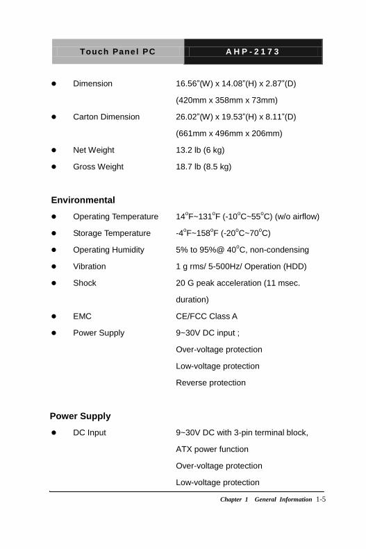
Dimension 16.56”(W) x 14.08”(H) x 2.87”(D)
(420mm x 358mm x 73mm)
Carton Dimension 26.02”(W) x 19.53”(H) x 8.11”(D)
(661mm x 496mm x 206mm)
Net Weight 13.2 lb (6 kg)
Gross Weight 18.7 lb (8.5 kg)
Environmental
Operating Temperature 14oF~131
oF (-10
oC~55
oC) (w/o airflow)
Storage Temperature -4oF~158
oF (-20
oC~70
oC)
Operating Humidity 5% to 95%@ 40oC, non-condensing
Vibration 1 g rms/ 5-500Hz/ Operation (HDD)
Shock 20 G peak acceleration (11 msec.
duration)
EMC CE/FCC Class A
Power Supply 9~30V DC input ;
Over-voltage protection
Low-voltage protection
Reverse protection
Power Supply
DC Input 9~30V DC with 3-pin terminal block,
ATX power function
Over-voltage protection
Low-voltage protection
Touch Panel PC A H P - 2 1 7 3
Chapter 1 General Information 1- 6
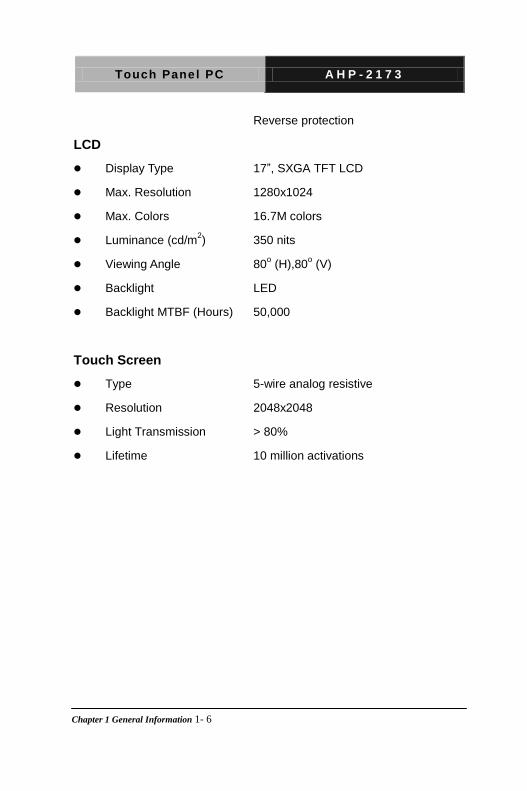
Reverse protection
LCD
Display Type 17”, SXGA TFT LCD
Max. Resolution 1280x1024
Max. Colors 16.7M colors
Luminance (cd/m2) 350 nits
Viewing Angle 80o (H),80
o (V)
Backlight LED
Backlight MTBF (Hours) 50,000
Touch Screen
Type 5-wire analog resistive
Resolution 2048x2048
Light Transmission > 80%
Lifetime 10 million activations

Touch Panel PC A H P - 2 1 7 3
Chapter 1 General Information 1-7
1.4 Dimension
AHP- 2 1 7 3Un its:m m
VESA 1 0 0
Touch Panel PC A H P - 2 1 7 3
Chapter 2 Quick Installation Guide 2-1
Hardware Installation
Chapter
2

Touch Panel PC A H P - 2 1 7 3
Chapter 2 Quick Installation Guide 2 - 2
2.1 Panelmount Installation
The display panel can be mounted into the wall. You will need the
screws along with the mounting brackets, which be packed in the
accessory box. Follow the steps below:
Before you start to follow the instructions, please place the
display panel into the wall. See the following illustration on the
left.
Step 1: Place the mounting brackets and plug the screw.
Step 2: Aim the mounting set at the hole on the monitor.
Step 3: Move the mounting set to the narrow gauge and fix it with
screws.
Step 4: You’ve completed the preliminary when the mounting set
is tightened. Next, repeat the steps and tighten all mounting set
around the monitor until the monitor is firmly mounting on the
wall.

Touch Panel PC A H P - 2 1 7 3
Chapter 2 Quick Installation Guide 2 - 3
1 2 3 4
Complete Illustration

Touch Panel PC A H P - 2 1 7 3
Chapter 2 Quick Installation Guide 2 - 4
2.2 COM1/2/3 RS-232/422/485 Serial Port Connector
COM1/COM3 RS-232 (D-sub 9 male)
Pin 2BSignal Pin 3BSignal
1 DCD 2 RXD
3 TXD 4 DTR
5 GND 6 DSR
7 RTS 8 CTS
9 RI
COM2 RS-232/422/485 (D-sub 9 male)
Pin Signal Pin Signal
1 DCD (422TXD-/485DATA-)
2 RXD (422RXD+)
3 TXD (422TXD+/485DATA+)
4 DTR (422RXD-)
5 GND 6 DSR
7 RTS 8 CTS
9 RI/+5Volt/+12Volt
1
2 4
5
6
7 8
9
1
2 4
5
6
7 8
9

Touch Panel PC A H P - 2 1 7 3
Chapter 2 Quick Installation Guide 2 - 5
2.3 Hard Disk Drive Installation
Step 1: Unfasten the screws of the heatsink
Step 2: Get the Bracket of Hard Disk Drive from the package
Touch Panel PC A H P - 2 1 7 3
Chapter 2 Quick Installation Guide 2 - 6
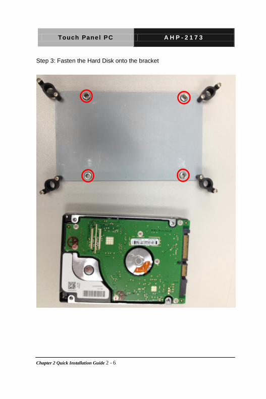
Step 3: Fasten the Hard Disk onto the bracket

Touch Panel PC A H P - 2 1 7 3
Chapter 2 Quick Installation Guide 2 - 7
Step 4: Fasten the screws of the hard disk bracket onto the AHP-2173

Touch Panel PC A H P - 2 1 7 3
Chapter 3 AMI BIOS Setup 3-1
AMI BIOS Setup
Chapter
3

Touch Panel PC A H P - 2 1 7 3
Chapter 3 AMI BIOS Setup 3-2
3.1 System Test and Initialization
These routines test and initialize board hardware. If the routines
encounter an error during the tests, you will either hear a few short
beeps or see an error message on the screen. There are two kinds
of errors: fatal and non-fatal. The system can usually continue the
boot up sequence with non-fatal errors.
System configuration verification
These routines check the current system configuration against the
values stored in the CMOS memory. If they do not match, the
program outputs an error message. You will then need to run the
BIOS setup program to set the configuration information in memory.
There are three situations in which you will need to change the
CMOS settings:
1. You are starting your system for the first time
2. You have changed the hardware attached to your system
3. The CMOS memory has lost power and the configuration
information has been erased.
The AHP-2173 CMOS memory has an integral lithium battery
backup for data retention. However, you will need to replace the
complete unit when it finally runs down.

Touch Panel PC A H P - 2 1 7 3
Chapter 3 AMI BIOS Setup 3-3
3.2 AMI BIOS Setup
AMI BIOS ROM has a built-in Setup program that allows users to modify the basic system configuration. This type of information is stored in battery-backed CMOS RAM so that it retains the Setup information when the power is turned off. Entering Setup Power on the computer and press <Del> or <F2> immediately. This will allow you to enter Setup. Main Set the date, use tab to switch between date elements. Advanced Enable disable boot option for legacy network devices. Chipset Host bridge parameters. Boot Enables/disable quiet boot option. Security Set setup administrator password. Save&Exit Exit system setup after saving the changes.

Touch Panel PC A H P - 2 1 7 3
Chapter 3 AMI BIOS Setup 3-4
Setup Menu
Setup submenu: Main
Options summary: (default setting)
System Date Day MM:DD:YYYY
Change the month, year and century. The ‘Day’ is changed
automatically.
System Time HH : MM : SS
Change the clock of the system.

Touch Panel PC A H P - 2 1 7 3
Chapter 3 AMI BIOS Setup 3-5
Setup submenu: Advanced
Options summary: (default setting)
ACPI Settings
System ACPI Parameters
CPU Configuration
CPU Configuration Parameters
SATA Configuration
SATA Device Options Settings
USB Configuration
USB Configuration Parameters

Touch Panel PC A H P - 2 1 7 3
Chapter 3 AMI BIOS Setup 3-6
Super IO
Configuration
System Super IO Chip Parameters
H/W Monitor
Monitor hardware status

Touch Panel PC A H P - 2 1 7 3
Chapter 3 AMI BIOS Setup 3-7
ACPI Settings
Options summary: (default setting)
ACPI Sleep State
Suspend Disabled
S1 only(CPU Stop
Clock)
S3 only(Suspend to
RAM)
Select the ACPI state used for System Suspend
Wake on Ring Enabled
Disabled
Enabled or disabled wake on ring function.

Touch Panel PC A H P - 2 1 7 3
Chapter 3 AMI BIOS Setup 3-8
RTC Wake Settings
Enable system to wake from S5 using RTC alarm.
RTC Wake Settings
Options summary: (default setting)
Wake system with
Fixed Time
Disabled
Enabled
Enable or disable System wake on alarm event. Wake up time is
setting by following settings.
Wake up hour 0-23

Touch Panel PC A H P - 2 1 7 3
Chapter 3 AMI BIOS Setup 3-9
Wake up minute 0-59
Wake up second 0-59
Wake system with
Dynamic Time
Disabled
Enabled
Enable or disable System wake on alarm event. Wake up time is
current time + Increase minutes.
Wake up minute
increase
1-5

Touch Panel PC A H P - 2 1 7 3
Chapter 3 AMI BIOS Setup 3-10
CPU Configuration
Options summary: (default setting)
Hyper-Threading Disabled
Enabled
En/Disable CPU Hyper-Threading function

Touch Panel PC A H P - 2 1 7 3
Chapter 3 AMI BIOS Setup 3-11
SATA Configuration
Options summary: (default setting)
SATA Controller(s) Disabled
Enabled
En/Disable SATA controller
Configure SATA as IDE
AHCI
Configure SATA controller operating as IDE/AHCI mode.
SATA Port 0/Port 1 Disabled
Enabled
En/Disable the selected port.

Touch Panel PC A H P - 2 1 7 3
Chapter 3 AMI BIOS Setup 3-12
SATA Port 0/Port 1 Hot
Plug
Disabled
Enabled
En/Disable Hot Plug feature for specified port.

Touch Panel PC A H P - 2 1 7 3
Chapter 3 AMI BIOS Setup 3-13
USB Configuration
Options summary: (default setting)
Legacy USB Support Enabled
Disabled
Auto
Enables BIOS Support for Legacy USB Support. When enabled,
USB can be functional in legacy environment like DOS. AUTO option
disables legacy support if no USB devices are connected. DISABLE
option will keep USB devices available only for EFI application
Device Name
(Emulation Type)
Auto
Floppy

Touch Panel PC A H P - 2 1 7 3
Chapter 3 AMI BIOS Setup 3-14
Forced FDD
Hard Disk
CD-ROM
If Auto. USB devices less than 530MB will be emulated as Floppy
and remaining as Floppy and remaining as hard drive. Forced FDD
option can be used to force a HDD formatted drive to boot as
FDD(Ex. ZIP drive)

Touch Panel PC A H P - 2 1 7 3
Chapter 3 AMI BIOS Setup 3-15
Super IO Configuration
Options summary: (default setting)
Serial Port 1/2/3
Configuration
Set Parameters of Serial Port 1/2/3
Restore AC Power Loss Power Off
Power On
Last State
Select AC power state when power is re-applied after a power
failure.

Touch Panel PC A H P - 2 1 7 3
Chapter 3 AMI BIOS Setup 3-16
Serial Port 1 Configuration
Options summary: (default setting)
Serial Port Disabled
Enabled
En/Disable specified serial port.
Change Settings
Auto
IO=3F8h; IRQ=4;
IO=3F8h;
IRQ=3,4,5,7,10,11,12;
IO=2F8h;
IRQ=3,4,5,7,10,11,12;

Touch Panel PC A H P - 2 1 7 3
Chapter 3 AMI BIOS Setup 3-17
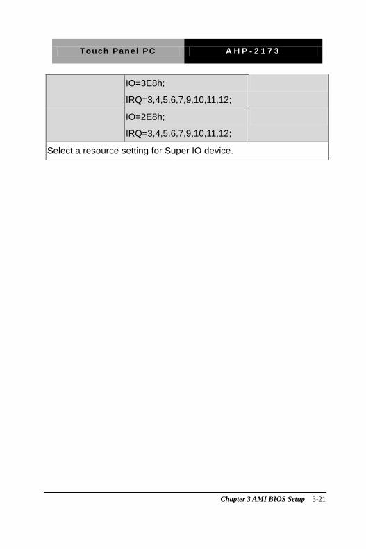
IO=3E8h;
IRQ=3,4,5,7,10,11,12;
IO=2E8h;
IRQ=3,4,5,7,10,11,12;
Select a resource setting for Super IO device.

Touch Panel PC A H P - 2 1 7 3
Chapter 3 AMI BIOS Setup 3-18
Serial Port 2 Configuration
Options summary: (default setting)
Serial Port Disabled
Enabled
En/Disable specified serial port.
Change Settings
Auto
IO=2F8h; IRQ=3;
IO=3F8h;
IRQ=3,4,5,7,10,11,12;
IO=2F8h;
IRQ=3,4,5,7,10,11,12;

Touch Panel PC A H P - 2 1 7 3
Chapter 3 AMI BIOS Setup 3-19
IO=3E8h;
IRQ=3,4,5,7,10,11,12;
IO=2E8h;
IRQ=3,4,5,7,10,11,12;
Select a resource setting for Super IO device.
COM2 Type Select RS232
RS422
RS485
Configure COM2 operated as RS232, RS422 or RS485.

Touch Panel PC A H P - 2 1 7 3
Chapter 3 AMI BIOS Setup 3-20
Serial Port 3 Configuration
Options summary: (default setting)
Serial Port Disabled
Enabled
En/Disable specified serial port.
Change Settings
Auto
IO=3E8h; IRQ=10;
IO=3F8h;
IRQ=3,4,5,6,7,9,10,11,12;
IO=2F8h;
IRQ=3,4,5,6,7,9,10,11,12;
Touch Panel PC A H P - 2 1 7 3
Chapter 3 AMI BIOS Setup 3-21
IO=3E8h;
IRQ=3,4,5,6,7,9,10,11,12;
IO=2E8h;
IRQ=3,4,5,6,7,9,10,11,12;
Select a resource setting for Super IO device.

Touch Panel PC A H P - 2 1 7 3
Chapter 3 AMI BIOS Setup 3-22
H/W Monitor

Touch Panel PC A H P - 2 1 7 3
Chapter 3 AMI BIOS Setup 3-23
Setup submenu: Chipset
Options summary: (default setting)
Host Bridge
Host Bridge Parameters
South Bridge
South Bridge Parameters

Touch Panel PC A H P - 2 1 7 3
Chapter 3 AMI BIOS Setup 3-24
Host Bridge
Options summary: (default setting)
Intel IGD
Configuration
Config Intel IGD Settings.
Touch Panel PC A H P - 2 1 7 3
Chapter 3 AMI BIOS Setup 3-25
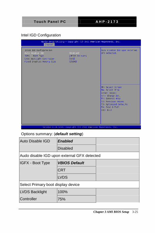
Intel IGD Configuration
Options summary: (default setting)
Auto Disable IGD Enabled
Disabled
Audo disable IGD upon external GFX detected
IGFX - Boot Type VBIOS Default
CRT
LVDS
Select Primary boot display device
LVDS Backlight
Controller
100%
75%

Touch Panel PC A H P - 2 1 7 3
Chapter 3 AMI BIOS Setup 3-26
50%
25%
0%
Adjust backlight brightness.
Fixed Graphics
Memory Size
128MB
256MB
Configure Fixed Graphics Memory Size

Touch Panel PC A H P - 2 1 7 3
Chapter 3 AMI BIOS Setup 3-27
South Bridge
Options summary: (default setting)
Power Mode ATX Type
AT Type
Select the power type used on the system
TPT Devices
HD audio and onboard LAN Settings.
PCI Express Root
Port
PCIe root port Settings.

Touch Panel PC A H P - 2 1 7 3
Chapter 3 AMI BIOS Setup 3-28
TPT Devices
Options summary: (default setting)
Azalia Controller Disabled
HD Audio
Enable or disabled Azalia controller
R8111E #1 Controller Disabled
Enabled
Enable or disable PCIE Lan.
R8111E #2 Controller Disabled
Enabled
Enable or disable PCIE Lan.

Touch Panel PC A H P - 2 1 7 3
Chapter 3 AMI BIOS Setup 3-29
PCI Express Root Port 0/1/2/3
Options summary: (default setting)
PCI Express Root
Port 0/1/2/3
Disabled
Enabled
Control the PCI Express Root Port.

Touch Panel PC A H P - 2 1 7 3
Chapter 3 AMI BIOS Setup 3-30
Setup submenu: Boot
Options summary: (default setting)
Quiet Boot Disabled
Enabled
En/Disable showing boot logo.
Launch RTL8111E
PXE OpROM
Disabled
Enabled
En/Disable PXE boot for RTL8111E LAN
Boot Option #X/
XXXX Drive BBS
Priorities

Touch Panel PC A H P - 2 1 7 3
Chapter 3 AMI BIOS Setup 3-31
The order of boot priorities.
BBS Priorities
Options summary: (default setting)
Boot Option #x Disabled
Device name
Sets the system boot order

Touch Panel PC A H P - 2 1 7 3
Chapter 3 AMI BIOS Setup 3-32
Setup submenu: Security
Options summary: (default setting)
Administrator
Password/
User Password
Not set

Touch Panel PC A H P - 2 1 7 3
Chapter 3 AMI BIOS Setup 3-33
You can install a Supervisor password, and if you install a supervisor
password, you can then install a user password. A user password
does not provide access to many of the features in the Setup utility.
Install the Password:
Press Enter on this item, a dialog box appears which lets you enter a
password. You can enter no more than six letters or numbers. Press
Enter after you have typed in the password. A second dialog box asks
you to retype the password for confirmation. Press Enter after you
have retyped it correctly. The password is required at boot time, or
when the user enters the Setup utility.
Removing the Password:
Highlight this item and type in the current password. At the next
dialog box press Enter to disable password protection.

Touch Panel PC A H P - 2 1 7 3
Chapter 3 AMI BIOS Setup 3-34
Setup submenu: Exit
Options summary: (default setting)
Save Changes and
Reset
Reset the system after saving the changes
Discard Changes and
Reset
Reset system setup without saving any changes
Restore Defaults
Restore/Load Default values for all the setup options.
Save as User Defaults
Touch Panel PC A H P - 2 1 7 3
Chapter 3 AMI BIOS Setup 3-35
Save the changes done so far as User Defaults
Restore User Defaults
Restore the User Defaults to all the setup options

Touch Panel PC A H P - 2 1 7 3
Chapter 4 Driver Installation 4 - 1
Driver Installation
Chapter
4

Touch Panel PC A H P - 2 1 7 3
Chapter 4 Driver Installation 4 - 2
The AHP-2173 comes with a DVD-ROM that contains all drivers and utilities that meet your needs.
Follow the sequence below to install the drivers:
Step 1 – Install Chipset Driver
Step 2 – Install VGA Driver
Step 3 – Install LAN Driver
Step 4 – Install Audio Driver
Step 5 – Install AHCI Driver (Optional)
Step 6 – Install TPM Driver
Step 7 – Install Touch Panel Driver
Step 8 – Install Serial Port Driver (Optional)
Please read instructions below for further detailed installations.

Touch Panel PC A H P - 2 1 7 3
Chapter 4 Driver Installation 4 - 3
4.1 Installation:
Insert the AHP-2173 DVD-ROM into the DVD-ROM Drive. And install the drivers from Step 1 to Step 8 in order.
Step 1 – Install Chipset Driver
1. Click on the STEP1-CHIPSET and select the OS folder your system is
2. Double click on the .exe file located in each OS folder
3. Follow the instructions that the window shows
4. The system will help you install the driver automatically
Step 2 – Install VGA Driver
For Windows® 7
1. Click on the STEP2-VGA folder and select the folder of WIN7_32
2. Double click on the Setup.exe file
3. Follow the instructions that the window shows
4. The system will help you install the driver automatically
For Windows® XP
1. Click on the STEP2-VGA folder and select the folder of WINXP_32
2. Install Framework 3.5
Double click on the dotnetfx35.exe
Follow the instructions that the window shows
The system will help you install the driver

Touch Panel PC A H P - 2 1 7 3
Chapter 4 Driver Installation 4 - 4
automatically
2. Install IEMGD
Double click on the IEMGDInstall.exe
Select the configuration
Follow the instructions that the window shows
The system will help you install the driver
automatically

Touch Panel PC A H P - 2 1 7 3
Chapter 4 Driver Installation 4 - 5
If you want to update driver, please uninstall driver first.
Uninstall IEMGD
1. Double click on the IEMGDInstall.exe
2. Follow the instructions that the window shows
3. The system will help you uninstall the driver automatically

Touch Panel PC A H P - 2 1 7 3
Chapter 4 Driver Installation 4 - 6
Step 3 – Install LAN Driver
1. Click on the STEP3-LAN folder and select the OS folder your system is
2. Double click on the setup.exe located in each OS folder
3. Follow the instructions that the window shows
4. The system will help you install the driver automatically
Step 4 – Install Audio Driver
1. Click on the STEP4-AUDIO folder and select the OS folder your system is
2. Double click on the Setup.exe located in each OS folder
3. Follow the instructions that the window shows
4. The system will help you install the driver automatically
Step 5 – Install AHCI Driver (optional, for SATA in AHCI mode only)
For Windows® 7:
1. Click on the STEP5-AHCI folder and select the WIN7_32 folder
2. Double click on the setup.exe file
3. Follow the instructions that the window shows
4. The system will help you install the driver automatically
For Windows® XP:
Please refer to Appendix C AHCI Setting

Touch Panel PC A H P - 2 1 7 3
Chapter 4 Driver Installation 4 - 7
Step 6 – Install TPM Driver
1. Click on the STEP6-TPM folder and select the OS folder your system is
2. Double click on the Setup.exe located in each OS folder
3. Follow the instructions that the window shows
4. The system will help you install the driver automatically
Step 7 – Install Touch Panel Driver
1. Click on the STEP7-TOUCH folder and select the OS folder your system is
2. Double click on the setup.exe located in each OS folder
3. Follow the instructions that the window shows
4. The system will help you install the driver automatically
Step 8 – Install Serial Port Driver (Optional)
1. Click on the STEP8-Serial Port Driver (Optional) folder and select the OS folder your system is
2. Double click on the Serial Patch v1.0.1_Eng.exe file located in each OS folder
3. Follow the instructions that the window shows
4. The system will help you install the driver automatically
Note: If the OS is Chinese version, you may click on Serial Patch v1.0.1. exe file located in each OS folder.

Touch Panel PC A H P - 2 1 7 3
Appendix A Programming the Watchdog Timer A-1
Programming the
Watchdog Timer
Appendix
A

Touch Panel PC A H P - 2 1 7 3
Appendix A Programming the Watchdog Timer A-2
A.1 Programming
AHP-2173 utilizes ITE 8783 chipset as its watchdog timer controller. Below are the procedures to complete its configuration and the AAEON initial watchdog timer program is also attached based on which you can develop customized program to fit your application.
Configuring Sequence Description
After the hardware reset or power-on reset, the ITE 8783 enters the
normal mode with all logical devices disabled except KBC. The initial state (enable bit ) of this logical device (KBC) is determined by the state of pin 121 (DTR1#) at the falling edge of the system reset during power-on reset.

Touch Panel PC A H P - 2 1 7 3
Appendix A Programming the Watchdog Timer A-3
There are three steps to complete the configuration setup: (1) Enter
the MB PnP Mode; (2) Modify the data of configuration registers; (3)
Exit the MB PnP Mode. Undesired result may occur if the MB PnP
Mode is not exited normally.
(1) Enter the MB PnP Mode
To enter the MB PnP Mode, four special I/O write operations are to
be performed during Wait for Key state. To ensure the initial state of
the key-check logic, it is necessary to perform four write opera-tions
to the Special Address port (2EH). Two different enter keys are
provided to select configuration ports (2Eh/2Fh) of the next step.
(2) Modify the Data of the Registers
All configuration registers can be accessed after entering the MB
PnP Mode. Before accessing a selected register, the content of
Index 07h must be changed to the LDN to which the register
belongs, except some Global registers.
(3) Exit the MB PnP Mode
Set bit 1 of the configure control register (Index=02h) to 1 to exit the
MB PnP Mode.

Touch Panel PC A H P - 2 1 7 3
Appendix A Programming the Watchdog Timer A-4
WatchDog Timer Configuration Registers
Configure Control (Index=02h)
This register is write only. Its values are not sticky; that is to say, a
hardware reset will automatically clear the bits, and does not
require the software to clear them.
Watch Dog Timer 1, 2, 3 Control Register (Index=71h,81h,91h
Default=00h)

Touch Panel PC A H P - 2 1 7 3
Appendix A Programming the Watchdog Timer A-5
Watch Dog Timer 1, 2, 3 Configuration Register (Index=72h,
82h, 92h Default=001s0000b)
Watch Dog Timer 1,2,3 Time-Out Value (LSB) Register
(Index=73h,83h,93h, Default=38h)
Watch Dog Timer 1,2,3 Time-Out Value (MSB) Register
(Index=74h,84h,94h Default=00h)

Touch Panel PC A H P - 2 1 7 3
Appendix A Programming the Watchdog Timer A-6
A.2 ITE8783 Watchdog Timer Initial Program
.MODEL SMALL
.CODE
Main:
CALL Enter_Configuration_mode
CALL Check_Chip
mov cl, 7
call Set_Logic_Device
;time setting
mov cl, 10 ; 10 Sec
dec al
Watch_Dog_Setting:
;Timer setting
mov al, cl
mov cl, 73h
call Superio_Set_Reg
;Clear by keyboard or mouse interrupt
mov al, 0f0h
mov cl, 71h
call Superio_Set_Reg
;unit is second.
mov al, 0C0H
mov cl, 72h
Touch Panel PC A H P - 2 1 7 3
Appendix A Programming the Watchdog Timer A-7
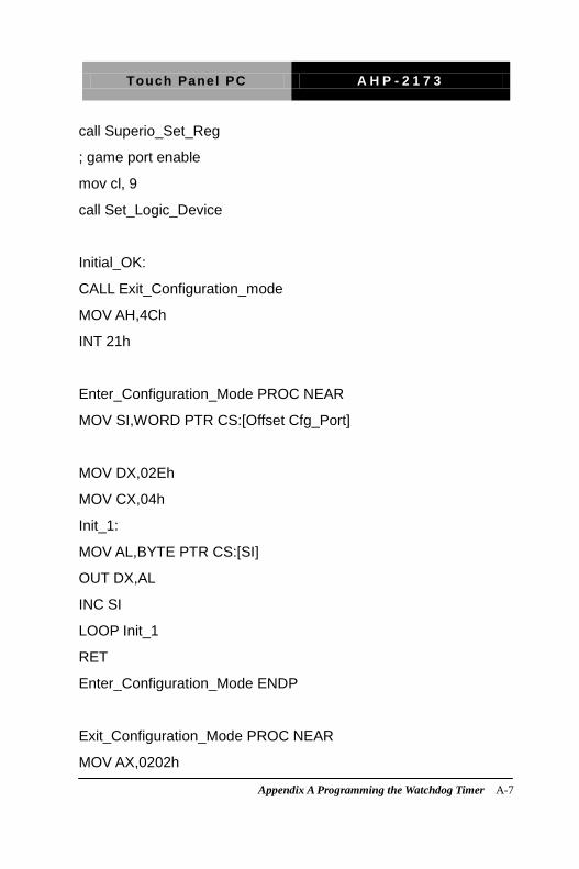
call Superio_Set_Reg
; game port enable
mov cl, 9
call Set_Logic_Device
Initial_OK:
CALL Exit_Configuration_mode
MOV AH,4Ch
INT 21h
Enter_Configuration_Mode PROC NEAR
MOV SI,WORD PTR CS:[Offset Cfg_Port]
MOV DX,02Eh
MOV CX,04h
Init_1:
MOV AL,BYTE PTR CS:[SI]
OUT DX,AL
INC SI
LOOP Init_1
RET
Enter_Configuration_Mode ENDP
Exit_Configuration_Mode PROC NEAR
MOV AX,0202h

Touch Panel PC A H P - 2 1 7 3
Appendix A Programming the Watchdog Timer A-8
CALL Write_Configuration_Data
RET
Exit_Configuration_Mode ENDP
Check_Chip PROC NEAR
MOV AL,20h
CALL Read_Configuration_Data
CMP AL,87h
JNE Not_Initial
MOV AL,21h
CALL Read_Configuration_Data
CMP AL,81h
JNE Not_Initial
Need_Initial:
STC
RET
Not_Initial:
CLC
RET
Check_Chip ENDP
Read_Configuration_Data PROC NEAR
MOV DX,WORD PTR CS:[Cfg_Port+04h]

Touch Panel PC A H P - 2 1 7 3
Appendix A Programming the Watchdog Timer A-9
OUT DX,AL
MOV DX,WORD PTR CS:[Cfg_Port+06h]
IN AL,DX
RET
Read_Configuration_Data ENDP
Write_Configuration_Data PROC NEAR
MOV DX,WORD PTR CS:[Cfg_Port+04h]
OUT DX,AL
XCHG AL,AH
MOV DX,WORD PTR CS:[Cfg_Port+06h]
OUT DX,AL
RET
Write_Configuration_Data ENDP
Superio_Set_Reg proc near
push ax
MOV DX,WORD PTR CS:[Cfg_Port+04h]
mov al,cl
out dx,al
pop ax
inc dx
out dx,al
ret
Superio_Set_Reg endp.Set_Logic_Device proc near

Touch Panel PC A H P - 2 1 7 3
Appendix A Programming the Watchdog Timer A-10
Set_Logic_Device proc near
push ax
push cx
xchg al,cl
mov cl,07h
call Superio_Set_Reg
pop cx
pop ax
ret
Set_Logic_Device endp
;Select 02Eh->Index Port, 02Fh->Data Port
Cfg_Port DB 087h,001h,055h,055h
DW 02Eh,02Fh
END Main
Note: Interrupt level mapping
0Fh-Dh: not valid
0Ch: IRQ12
.
.
03h: IRQ3
02h: not valid
01h: IRQ1
00h: no interrupt selected

Touch Panel PC A H P - 2 1 7 3
Appendix B I/O Information B - 1
I/O Information
Appendix
B

Touch Panel PC A H P - 2 1 7 3
Appendix B I/O Information B - 2
B.1 I/O Address Map

Touch Panel PC A H P - 2 1 7 3
Appendix B I/O Information B - 3
Touch Panel PC A H P - 2 1 7 3
Appendix B I/O Information B - 4
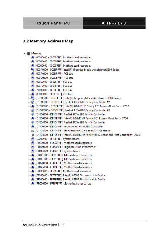
B.2 Memory Address Map

Touch Panel PC A H P - 2 1 7 3
Appendix B I/O Information B - 5
B.3 IRQ Mapping Chart
B.4 DMA Channel Assignments

Touch Panel PC A H P - 2 1 7 3
Appendix C AHCI Setting C-1
AHCI Setting
Appendix
C

Touch Panel PC A H P - 2 1 7 3
Appendix C AHCI Setting C-2
B.1 Setting AHCI
OS installation to setup AHCI Mode.
Step 1: Copy the files below from “Driver CD -> STEP5-AHCI\WINXP_32”
to Disk
Step 2: Connect the USB Floppy to the system
Step 3: Setup OS

Touch Panel PC A H P - 2 1 7 3
Appendix C AHCI Setting C-3
Step 4: Press “F6”
Step 5: Choose “S”

Touch Panel PC A H P - 2 1 7 3
Appendix C AHCI Setting C-4
Step 6: Choose “Intel(R) NM10 Express Chipset”
Step 7: It will show the model number you select and then press “ENTER
Step 8: Setup is loading files, follow the instruction when it's finished