Embed Size (px)
Citation preview
Page 1
Touch Score 3
Ten Pin Bowling Scoring System
Reference Guide
By A.K.Microsystems International www.touchscore.com

Page 2
IMPORTANT SAFETY WARNINGS ! The hardware devices described here are low voltage, low current devices and
MUST NOT be connected or exposed to mains or hazardous voltages under any
circumstances. Connect these devices only to other SELV (safe extra low voltage)
circuits. All electrical work associated with this system must conform to the relevant
local codes, and must be carried out by suitably qualified persons only. It is the
installer’s responsibility to ensure the installation meets any applicable
electrical safety and personal safety requirements. Exposed metal surfaces on
all devices must be connected to a suitable ground point. See also Touch Score
Machine Interface Unit
The software and hardware devices described here may be installed in such a way as
to facilitate control of the pinspotters and bumpers In this case, this software and
these devices may activate and cycle the pinspotters and bumpers AT ANY TIME
and WITHOUT ANY WARNING. It is therefore ESSENTIAL that other safety
devices are installed to prevent personal injury from the pinspotters and bumpers.
This software and these devices can also be installed without this functionality,
without affecting their ability to perform other functions.
The Touch Score lighting system is intended for control of safe lighting fixtures only.
Any fixtures that have any risk of causing damage or personal injury (such as high
intensity lasers) must NOT be used.
Copyright © 2012-2021 A.K.Microsystems Australia. All Rights Reserved. This manual and the software
described in it are copyrighted with all rights reserved.
Disclaimer Although every reasonable attempt has been made to ensure the accuracy and completeness of this
document, A.K.Microsystems International Pty Ltd accepts no responsibility for any errors or omissions. A.K.Microsystems International Pty Ltd reserves the right to edit or append this document at any time without
notice.
Trademarks Various company names, brand names, and product names included in this manual are trademarks
or registered trademarks of their respective companies.
The following sections apply only to devices manufactured by A.K.Microsystems International P/L. Where the
device is manufactured under licence or otherwise by others, refer to the manufacturer for warranty details.
Warranty The manufacturer, A.K.Microsystems International Pty Ltd warrants the TS MIU and TS MPA
against defects in material and workmanship for a period of one year from the date of purchase. If such a defect
is found during the warranty period, A.K.Microsystems International Pty Ltd will, at its option, repair or replace the product provided the product is returned to A.K.Microsystems International Pty Ltd with proof of purchase.
The customer is responsible for all freight charges. The customer must obtain written authorisation from
A.K.Microsystems International Pty Ltd prior to shipping.
This warranty does not apply to defects due directly or otherwise to misuse, abuse, negligence, accident,
incorrect installation, unauthorised repairs or alterations, or the application of excessive voltage or current due to any cause. This warranty does not apply if the serial number has been removed, defaced or altered.

Page 3
A.K.Microsystems International Pty Ltd makes no warranties as to the merchantability, performance, or fitness for a particular use, of this product, and accepts no responsibility for any subsequent loss or damages caused
directly or otherwise by the use or failure of this product, except where required by law.
This warranty does not limit the statutory rights of the customer.
FCC Notice for TS MIU, TS MPA and UBT. This equipment has been tested and found to comply with the limits for a Class A digital device, pursuant to part 15 of the FCC Rules. These limits are designed to provide
reasonable protection against harmful interference when the equipment is operated in a commercial environment.
This equipment generates, uses, and can radiate radio frequency energy and, if not installed and used in accordance with the instruction manual, may cause harmful interference to radio communications. Operation of
this equipment in a residential area is likely to cause harmful interference in which case the user will be required
to correct the interference at his own expense.
Acknowledgements OpenMoko’s dfu_util, LibUSB-Win32 (see licence.txt in drivers folder), LeafLabs
bootloader www.leaflabs.com
Document Revision 3.20.21, November 2021
Page 4
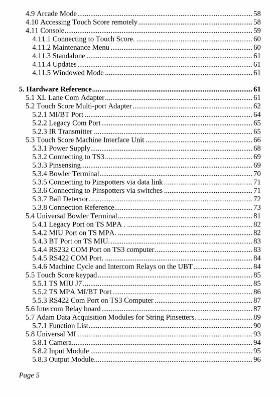
Contents
1. Overview ............................................................................................................ 7
2. Compatible Equipment .................................................................................... 9 2.1 Computer ....................................................................................................... 9 2.2 Overhead TVs ............................................................................................. 10 2.3 Lower Monitors. .......................................................................................... 12 2.4 Machine Interface ........................................................................................ 13 2.5 Bowler Console. .......................................................................................... 14
2.5.1 AS80/90 Keypad Re-labeling ............................................................... 15 2.6 Lighting ....................................................................................................... 16 2.7 Coin Acceptors & Ticket Dispensers .......................................................... 17 2.8 Smart Card Readers (NFC) ......................................................................... 17
3. Standard Configurations ................................................................................ 19 3.1 Magicscore/Accuscore 1 ............................................................................. 19 3.2 XL/Boss....................................................................................................... 20 3.3 AS80/90 ...................................................................................................... 21 3.4 Frameworx .................................................................................................. 23 3.5 New Installations ......................................................................................... 25
4. Software ........................................................................................................... 26 4.1 Installation ................................................................................................... 26 4.2 Updates ........................................................................................................ 29 4.3 Startup ......................................................................................................... 29 4.4 Setup Menu ................................................................................................. 31 4.5 Operation ..................................................................................................... 32 4.6 Camera Setup .............................................................................................. 33
4.6.1 Touch Score Camera ............................................................................ 33 4.6.2 AMF Camera ........................................................................................ 38
4.7 Standalone Mode ......................................................................................... 38 4.8 Virtual Desk ................................................................................................ 39
4.8.1 Setup Tab (Standalone Only) ............................................................... 40 4.8.2 Universal MI Tab (Standalone Only) ................................................... 47 4.8.3 Scoring Tab (Trial Only) ...................................................................... 50 4.8.4 Display Tab .......................................................................................... 51 4.8.5 Other Tab .............................................................................................. 53 4.8.6 Color Tab .............................................................................................. 55 4.8.7 Messages Tab ....................................................................................... 56 4.8.8 Tokens & Tickets Tab .......................................................................... 56 4.8.9 Update Tab (Standalone Only) ............................................................. 57
Page 5
4.9 Arcade Mode ............................................................................................... 58 4.10 Accessing Touch Score remotely .............................................................. 58 4.11 Console ...................................................................................................... 59
4.11.1 Connecting to Touch Score. ............................................................... 60 4.11.2 Maintenance Menu ............................................................................. 60 4.11.3 Standalone .......................................................................................... 61 4.11.4 Updates ............................................................................................... 61 4.11.5 Windowed Mode ................................................................................ 61
5. Hardware Reference ....................................................................................... 61 5.1 XL Lane Com Adapter ................................................................................ 61 5.2 Touch Score Multi-port Adapter ................................................................. 62
5.2.1 MI/BT Port ........................................................................................... 64 5.2.2 Legacy Com Port .................................................................................. 65 5.2.3 IR Transmitter ...................................................................................... 65
5.3 Touch Score Machine Interface Unit .......................................................... 66 5.3.1 Power Supply ........................................................................................ 68 5.3.2 Connecting to TS3 ................................................................................ 69 5.3.3 Pinsensing ............................................................................................. 69 5.3.4 Bowler Terminal ................................................................................... 70 5.3.5 Connecting to Pinspotters via data link ................................................ 71 5.3.6 Connecting to Pinspotters via switches ................................................ 71 5.3.7 Ball Detector ......................................................................................... 72 5.3.8 Connection Reference........................................................................... 73
5.4 Universal Bowler Terminal ......................................................................... 81 5.4.1 Legacy Port on TS MPA . .................................................................... 82 5.4.2 MIU Port on TS MPA. ......................................................................... 82 5.4.3 BT Port on TS MIU. ............................................................................. 83 5.4.4 RS232 COM Port on TS3 computer. .................................................... 83 5.4.5 RS422 COM Port. ................................................................................ 84 5.4.6 Machine Cycle and Intercom Relays on the UBT ................................ 84
5.5 Touch Score keypad .................................................................................... 85 5.5.1 TS MIU J7 ............................................................................................ 85 5.5.2 TS MPA MI/BT Port ............................................................................ 86 5.5.3 RS422 Com Port on TS3 Computer ..................................................... 87
5.6 Intercom Relay board .................................................................................. 87 5.7 Adam Data Acquisition Modules for String Pinsetters. .............................. 89
5.7.1 Function List ......................................................................................... 90 5.8 Universal MI ............................................................................................... 93
5.8.1 Camera .................................................................................................. 94 5.8.2 Input Module ........................................................................................ 95 5.8.3 Output Module ...................................................................................... 96
Page 6
5.8.4 MI-X ..................................................................................................... 98 5.8.5 AMF-X ............................................................................................... 101
5.9 UCL Hardware .......................................................................................... 103
Page 7
1. Overview
Touch Score 3 (TS3) is a Windows based scoring system for bowling centers.
It is intended primarily as an upgrade to legacy systems, although it can also
be used for new installations.
When installed as an upgrade, TS3 can often retain and reuse much of the
existing equipment such as bowler consoles, pinspotter interfaces, pin sensing
devices and cabling.
Where new equipment is desired, TS3 uses standard hardware available from
multiple third parties wherever possible. Examples include the scoring
computers, cameras, and TVs.
TS3 connects directly to LCD flat screens without the need for convertors.
A.K.Microsystems supplies the software for the system, and also licences the
manufacture of various accessory devices as listed below. These items are then
integrated into a total scoring system by a system integrator.
• Touch Score Machine Interface Unit (TS MIU) – provides connections
to the pinspotters, cameras, bumpers etc.
• Touch Score Multi-port Adapter (TS MPA) – provides ports for
connection to the MIU, TV remote control, bowler consoles, legacy APS,
data processors and pinsetter controllers.
• Universal Bowler Terminal Board (UBT) – interface board for keypads.
Various adapters are available for legacy keypads. See the Universal
Bowler Terminal guide for details.
This manual covers only the software and devices listed above. Consult the
relevant manufacturer’s manual for more information on other devices in the
system.
A customised keypad and stanchion is available from our US partners, such
that everything the bowler sees can be new, even when retaining much of the
back end scoring equipment such as cameras and pinspotter interface units.
Page 8
Touch Score can be installed as a standalone scoring system or with a Touch
Desk central management system. Touch Desk can manage both TS3 and
legacy scoring side by side in the same center..
TS3 supports regular 10 Pin, Candlepin, 2 and 3 ball Duckpin and 5 Pin
bowling.
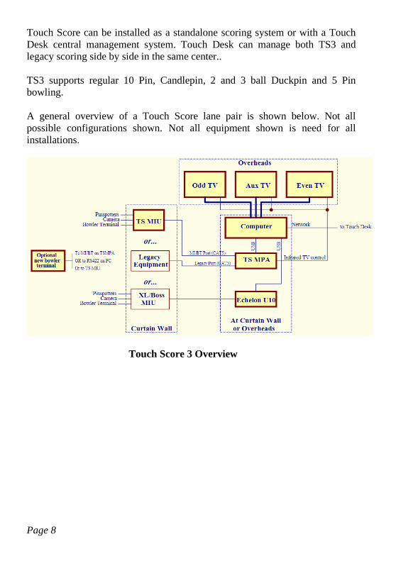
A general overview of a Touch Score lane pair is shown below. Not all
possible configurations shown. Not all equipment shown is need for all
installations.
Touch Score 3 Overview
Page 9
2. Compatible Equipment
TS3 can be installed in many different configurations and in conjunction with
a wide variety of other equipment. For this reason, each individual installation
of TS3 needs to be designed based on individual requirements.
This section details the equipment that can be used with TS3.
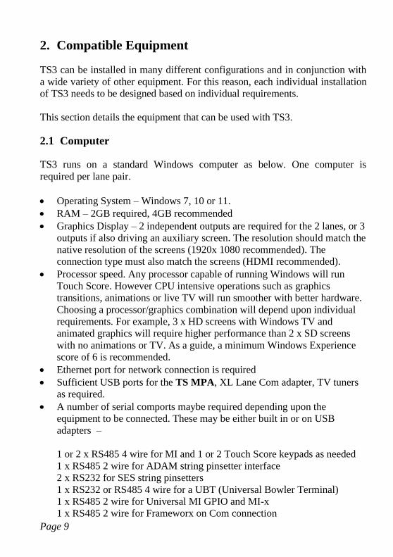
2.1 Computer
TS3 runs on a standard Windows computer as below. One computer is
required per lane pair.
• Operating System – Windows 7, 10 or 11.
• RAM – 2GB required, 4GB recommended
• Graphics Display – 2 independent outputs are required for the 2 lanes, or 3
outputs if also driving an auxiliary screen. The resolution should match the
native resolution of the screens (1920x 1080 recommended). The
connection type must also match the screens (HDMI recommended).
• Processor speed. Any processor capable of running Windows will run
Touch Score. However CPU intensive operations such as graphics
transitions, animations or live TV will run smoother with better hardware.
Choosing a processor/graphics combination will depend upon individual
requirements. For example, 3 x HD screens with Windows TV and
animated graphics will require higher performance than 2 x SD screens
with no animations or TV. As a guide, a minimum Windows Experience
score of 6 is recommended.
• Ethernet port for network connection is required
• Sufficient USB ports for the TS MPA, XL Lane Com adapter, TV tuners
as required.
• A number of serial comports maybe required depending upon the
equipment to be connected. These may be either built in or on USB
adapters –
1 or 2 x RS485 4 wire for MI and 1 or 2 Touch Score keypads as needed
1 x RS485 2 wire for ADAM string pinsetter interface
2 x RS232 for SES string pinsetters
1 x RS232 or RS485 4 wire for a UBT (Universal Bowler Terminal)
1 x RS485 2 wire for Universal MI GPIO and MI-x
1 x RS485 2 wire for Frameworx on Com connection
Page 10
See the SoftwareInstallation section for port settings.
Careful consideration should be given to the location of the TS3 computer. For
centers with overheads, the preferred position is at the overheads, as this
allows for optimal HDMI connection to the TVs. Also, the TS MPA, if used
should be close to both the TVs and the computer.
Where there are only lower monitors, and no overheads, the TS3 computer is
best located at the bowler’s console.
However, TS3 may be located on the curtain wall, in which case the TVs
should be connected using either VGA, or HDMI extenders. If IR remote
control of the TVs is also required, the outputs of the TS MPA will need to be
extended with CAT5 cable.
Where there are both upper and lower monitors, a suitable splitter and cabling
will be required, as both the upper and lower monitors are driven from the
same source.
2.2 Overhead TVs
Any monitor or TV that is compatible with the Windows computer can be
used. TS3 will adapt to any resolution that the hardware supports.
The monitor should connect to the computer using either HDMI, or VGA.
HDMI gives the best quality, but is normally limited to short distances unless
an extender device is used.
VGA cables can run the length of the bowling lane without problems, but the
quality and maximum resolution may be reduced.
There are several options for controlling power to the TV and displaying other
signals such as live TV, as detailed below. Any combination of these options
can be used.
In order to choose a suitable TV and control option, consider how the system
will be used. For example, will TV be displayed when the lane is off? Do all
Page 11
TVs need to be able to display different channels or just a common feed? Do
the TVs need to be powered down when not in use?
• Windows Power Control. TS3 can use Windows to put the TV or
monitor into standby mode when not in use. All computer monitors should
support this feature, and some TVs may also. No extra hardware is
required as control is via the normal video cabling.
• Windows TV. USB TV Tuners can be fitted to the computer, such that
any TV channel can be displayed full screen, or in a window within the
score grid, or as a background to the score grid. This method is suitable for
computer monitors that don’t have their own built in tuner.
Each screen requires its own USB Tuner, so that for 2 lanes a dual tuner is
required. If live TV is also required on an auxiliary screen, 3 tuners are
needed.
Each screen can display a different channel.
Bowlers can be given the option to choose their own channel.
TS3 supports any tuner that has either an Analog WDM driver, or a digital
BDA driver that is compatible with Windows Media Center.
• Infra Red Remote Control. The optional TS MPA (multi port adapter)
allows control of the TV by emulating the TVs own handheld remote. It
can turn the TV on and off, and change from score grid to TV or to any
other input. It can control the volume, and any additional functions that are
available on the remote.
If supported by the TV, it can display the score alongside a TV picture
using PIP (Picture-in-Picture) mode.
Background display of TV, where the TV picture is behind the score grid,
is not possible.
Each screen can display a different channel.
For more information, see the TS MPA reference, and the separate TV
Controller document. Note that IR Control may not be possible with some
TVs.
Page 12
• Legacy Control. Basic power control and switching between score and
TV is built into some legacy display systems, and their modern LCD
replacements. Depending upon the type, the TS MIU may be able to use
this legacy control equipment for simple power on/off, and score/TV
switching. See the MIU Reference for more information.
There is no channel control, so all lanes would display the same “channel”
from a central distribution system.
• Manual Control. Some centers may find it acceptable to just use the TV’s
hand held remote to control the TV. The screens can be set to display
advertising when the lane is not in use, or simply go black, but would
always remain in the fully powered state unless the hand held remote was
used.
The hand held remote would be required to switch between score grid and
TV, or to change channels.
• Auto TV. Some TVs have the ability to switch to an input when a signal
becomes available, and then back to TV when that signal is lost. TS3 can
use this ability to automatically switch from TV to score at check in, and
back to TV at check out. However no channel control is possible without
the use of the handheld remote.
Likewise, some TVs will automatically power down when the signal is
lost, and return to the fully on state when the signal returns. Unfortunately,
many of these display “No Signal” or similar, and this is generally not
desirable.
Many of these options require a suitable distribution system consisting of
amplifiers and splitters to distribute the TV and/or video signal to each TV or
TS3 computer. This distribution system is not part of TS3.
2.3 Lower Monitors.
TS3 does not currently support a separate output for lower monitors. Therefore
when lowers are required, a suitable splitter/extender is required to duplicate
the overhead output on the lowers.
Page 13
However, TS3 does support using Windows Tablets for bowler consoles, and
these do provide a lower scoring grid display.
If only lowers are required, then the TS3 computer can be mounted in the
lower console and connect directly to the lowers as if they were overheads.
The same guidelines listed above regarding cable types, lengths and video
quality for the upper monitors also applies to the lowers.
2.4 Machine Interface
The following options are available to connect the TS3 computer to the
pinspotters and pin sensing equipment.
• TS3 Machine Interface Unit. The TS MIU has all the necessary
connections for cameras and pinspotters, and connects to TS3 via the TS
MPA or a serial port on the computer. Either a standard video camera or
an AMF Accucam can be used for pinsensing. See the MIU reference for
details.
• Brunswick AS80/90 Data Processor. A Brunswick data processor and
camera can be connected to the TS3 computer using the TS MPA. See the
TS MPA reference for detail.
• AMF APS. An AMF APS as used by Magicscore and Accuscore I
systems can be connected to TS3 via the TS MPA. See the TS MPA
reference for detail.
• XL/Boss MI or Lane Com. TS3 can connect to an XL/Boss lane com
cable using an adapter. See XL Lane Com Adapter. This connection may
include an MIU, camera and bowler terminal.
• Frameworx. TS3 can connect to a Frameworx LLAN and supports the
following devices - Pinsetter Interface box and data processor, GSX direct
connection, Frameworx bumper controller, and Frameworx keypads. The
LLAN is connected either via a TS MPA or a standard RS485 Com port.
See the TS MPA reference for details. For systems using the TS MIU or
Universal MI, this connection can also be used for controlling a
Frameworx bumper controller only.
Page 14
• Adam Data Acquisition Modules for String Pinsetters. TS3 uses off the
shelf Adam interface 1/O modules to read the switches on a string
pinsetter. See Adam Data Acquisition Modules for String Pinsetters.
• SES Pinsetter Direct. TS3 can connect directly to two SES String
Pinsetters via two RS232 serial ports.
• Funk/Spellmann direct. TS3 can connect directly to two Funk string
pinsetters with Spellman Modul Tech controllers, via two RS232 serial
ports.
• Universal MI. The Universal MI is built in to the TS3 software, and uses
mostly general purpose I/O modules (GPIO) to connect to a wide range of
pinspotting equipment. It offers similar functionality to the TS MIU. It can
be used with an IP (network connected) camera, or an AMF A+ Accucam.
It can also interface to generic string pinsetters using a camera and
minimal connections.
See the Universal MI reference for more details.
2.5 Bowler Console.
The possible options for bowler terminals will depend upon the machine
interface equipment in use as detailed below –
• ALL Types. The Touch Score keypad and stanchion can be used with
any configuration of Touch Score. It is connected via the TS MIU, the TS
MPA device, or directly via an RS422 com port on the TS3 computer.
Both one keypad per pair, and one per lane (dual) are supported.
• All Types. The Touch Score Console is a program that runs on a
windows tablet and can be used in place of a keypad. It requires a network
connection to communicate with the TS3 computer. Both one console per
pair and one per lane are supported. The console provides either a virtual
keypad display that functions the same as a normal keypad, or a fully
interactive system including score grid display.
• XL/BOSS MIU. When connected to an XL/Boss MIU, then the existing
single (1 per pair) or dual (2 per pair) XL/Boss keypad console can be
Page 15
used. No additional wiring to TS3 is required, as the keypads
communicate over the same LANECOM connection as the MIU.
• Frameworx Pinsetter Interface. When connected to a Frameworx
Pinsetter Interface via LLAN, a keypad based Frameworx bowler console
can be used. The LLAN connections are shared between the Pinsetter
Interface and the bowler terminal. Touch screen consoles are not currently
supported.
• TS MIU. This MIU supports either a single Accuscore Plus bowler
terminal or a Universal Bowler Terminal board with any of its supported
keypad types, including dual keypads.
• ALL Types. A Universal Bowler Terminal Board can be used with any
configuration and allows a variety of keypads to be connected either to the
TS MIU, to the TS MPA device, or directly via a com port to the TS3
computer. Keypad support includes Magicscore single and triple,
Accuscore 1, 2 and Plus (single or dual), AS80/90 and XL/Boss single or
dual. See the Universal Bowler Terminal guide for more details.
• No Bowler Console. TS3 can be used without any bowler’s console at all.
The front counter is used to enter names and make score corrections, and
the Auto Next and End Game function is enabled to advance to each new
game.
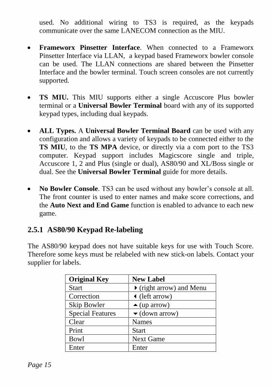
2.5.1 AS80/90 Keypad Re-labeling
The AS80/90 keypad does not have suitable keys for use with Touch Score.
Therefore some keys must be relabeled with new stick-on labels. Contact your
supplier for labels.
Original Key New Label
Start (right arrow) and Menu
Correction (left arrow)
Skip Bowler (up arrow)
Special Features (down arrow)
Clear Names
Print Start
Bowl Next Game
Enter Enter
Page 16
Although the Enter key is not relabeled, it is included in the new labels so that
the entire column of keys matches.
2.6 Lighting
Touch Score can control the lighting fixtures on the lane, using the industry
standard DMX512 protocol. Any fixture which supports this protocol can be
used, and typically includes pin deck lighting, overhead lighting and chaser
lights.
Touch Score can adjust the lighting depending upon whether the lane is
checked in or not, the current game number and even the current bowler’s
chosen theme. Touch Score can also run light shows that are triggered by
bowling. For example, it can run a chaser sequence down the lanes when a
strike is bowled.
A centralized lighting controller or light desk can optionally be used to
generate whole of house light shows, which are then merged with the light
shows from Touch Score.
Touch Score requires one or two USB DMX lighting controllers to connect
with the lights. The recommended controller is the DMXKing
ultraDMX2Pro. This controller has the following connections –
• USB – connect to Touch Score at each lane pair. This device uses a com
port driver which must be configured as COM16 for the first controller
and COM17 for the second if used.
• DMX 1 or A – the DMX output for the odd lane
• DMX 2 or B – the DMX output for the even lane
• Ethernet – connect to the central controller (optional)
Note that if connection to a central lighting controller is not required, then any
controller that is “Enttech Pro” compatible and has dual universe DMX
outputs can be used.
Both Port A & B on the UltraDMX2Pro must be configured for DMX output
mode, and the Universe for each port must be set as per the address
configuration. The merge mode is typically HTP with Time Out All Sources
enabled. Note that devices with firmware later than 3.5 will be setup
automatically by Touch Score.
Page 17
See the Lighting chapter in the Touch Desk manual for more information,
including how to setup the addressing for the lighting fixtures, and whether 1
or 2 controllers will be required.
When using Touch Score in standalone, the default fixture addresses must be
used.
2.7 Coin Acceptors & Ticket Dispensers
Touch Score can interface to coin acceptors and redemption ticket dispensers
so as to operate as an arcade game on mini or full size bowling.
The interface allows for the reading of a signal for each coin inserted, and the
output of a pulse for each ticket that is to be issued. These signals are similar
to that used in the Universal Card Link specification, and should allow a wide
range of coin acceptors, ticket dispensers and player card systems to be used.
For details of the interface hardware, see UCL Hardware.
2.8 Smart Card Readers (NFC)
Customers can be issued smart cards which they can use to identify themselves
to the scoring system. These cards can also be used to purchase games via
tokens, earn rewards via tickets, or order food and drink from prepaid credit.
See the Touch Desk manual for more information on the use of smart cards.
The smart cards use NFC technology and require a suitable card reader to be
connected to either the bowler’s console computer, or the touch score
computer itself.
If a single console is fitted to a pair, then a single reader must be connected to
the console. Any readers connected to the TS3 computer are ignored.
If dual consoles are fitted, each must have its own reader attached. Any readers
connected to the TS3 computer are ignored.
If no consoles are fitted, then a single reader must be connected to the TS
computer, and can only be used for purchasing games with virtual tokens and
earning rewards with virtual tickets.

Page 18
In the cases where a single reader is shared between a pair of lanes, Touch
Score will intelligently use the reader for the appropriate lane based on the
current context and prompts at each lane. Where either lane is available for
check in, it will alternate each check in where possible.
The recommended card reader is Advanced Card Systems ACR-122U which
connects via USB, although other types that support the standard windows
driver may be used.
Page 19
3. Standard Configurations
Following are some standard configurations used for both upgrading existing
systems and for new installations.
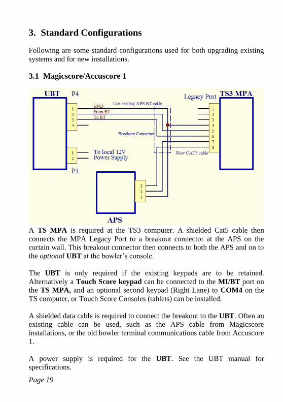
3.1 Magicscore/Accuscore 1
A TS MPA is required at the TS3 computer. A shielded Cat5 cable then
connects the MPA Legacy Port to a breakout connector at the APS on the
curtain wall. This breakout connector then connects to both the APS and on to
the optional UBT at the bowler’s console.
The UBT is only required if the existing keypads are to be retained.
Alternatively a Touch Score keypad can be connected to the MI/BT port on
the TS MPA, and an optional second keypad (Right Lane) to COM4 on the
TS computer, or Touch Score Consoles (tablets) can be installed.
A shielded data cable is required to connect the breakout to the UBT. Often an
existing cable can be used, such as the APS cable from Magicscore
installations, or the old bowler terminal communications cable from Accuscore
1.
A power supply is required for the UBT. See the UBT manual for
specifications.
Page 20
3.2 XL/Boss.
The TS3 computer can be used as a replacement for the XL/Boss chassis, with
most other components remaining the same. The computer can be mounted on
the curtain wall, or at the overheads.
The original XL/Boss chassis uses VGA for connection to the overheads. So it
is often convenient if the new computer and monitors also use VGA, as the
existing cabling can be re-used. This is especially true if the new computer is
on the curtain wall.
TS3 does not provide power control of the TVs as the original XL/Boss
chassis does. Instead, use one of the alternative options such as IR control. If
legacy power control is fitted it may need to be bypassed to power up the TVs.
If the TV Tuner function of the original chassis is to be duplicated, then TV
tuners must be fitted to the TS3 computer, or an alternative method such as IR
control must be used to provide a TV picture. See Windows TV and IR
Control.
An Echelon U10 Network Interface device connects between a USB port on
the TS3 computer and the existing LANECOM cable. This provides
connectivity to the Machine Interface Unit (if present), camera and bowler
terminal.
The two terminals on the Echelon U10 connect to pins 1&2 (usually Red &
Black wires) of the existing LANECOM cable for XL centers that have the 4
pin SDL connectors.
For BOSS centers with RJ45 type connectors on the LANECOM cable, the
required wires are on pins 7&8.
If the existing bowler terminal is not to be retained, there are two options –
• One or two Touch Score keypad(s) connected to an RS422 port
(COM4/5) on the TS3 computer.
• One or two Touch Score Consoles (tablets)
Page 21
• A Universal Bowler Terminal with any supported keypad type,
connected to com 4 on the TS3 computer.
The existing AMF camera can be retained, or an IP camera connected to TS3
via ethernet can be used instead.
The TS3 computer must be connected to the Touch Desk Windows network,
not to the existing XL scoring network which may still be in use on other
lanes.
The windows driver for the Echelon U10 must be installed.
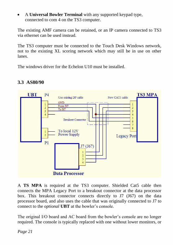
3.3 AS80/90
A TS MPA is required at the TS3 computer. Shielded Cat5 cable then
connects the MPA Legacy Port to a breakout connector at the data processor
box. This breakout connector connects directly to J7 (J67) on the data
processor board, and also uses the cable that was originally connected to J7 to
connect to the optional UBT at the bowler’s console.
The original I/O board and AC board from the bowler’s console are no longer
required. The console is typically replaced with one without lower monitors, or
Page 22
the lowers can be retained and connected with additional cabling and splitters
to the overheads.
Note that the data processor box requires a 28VAC power supply. The
transformer from the original console must therefore be retained, and wired
directly to the data processor power cable, as the existing AC board will be
discarded.
The UBT is only required if the existing keypads are to be retained.
Alternatively a Touch Score keypad can be connected to the MI/BT port on
the TS MPA, and an optional second keypad (right Lane) to COM4 on the
TS computer, or Touch Score Consoles (tablets) can be installed.
A power supply is required for the UBT. See the UBT manual for
specifications.
For systems with lowers only, the TS3 computer can be located in the lower
console rather than at the overheads. To simplify installation in this case,
connect the UBT to the MIU Port on the TS MPA rather than splitting the
legacy port cable.
Page 23
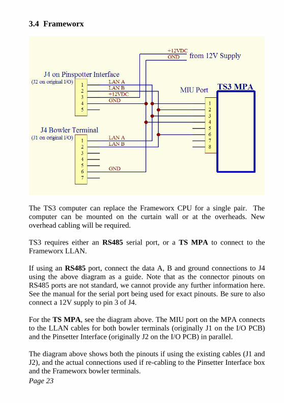
3.4 Frameworx
The TS3 computer can replace the Frameworx CPU for a single pair. The
computer can be mounted on the curtain wall or at the overheads. New
overhead cabling will be required.
TS3 requires either an RS485 serial port, or a TS MPA to connect to the
Frameworx LLAN.
If using an RS485 port, connect the data A, B and ground connections to J4
using the above diagram as a guide. Note that as the connector pinouts on
RS485 ports are not standard, we cannot provide any further information here.
See the manual for the serial port being used for exact pinouts. Be sure to also
connect a 12V supply to pin 3 of J4.
For the TS MPA, see the diagram above. The MIU port on the MPA connects
to the LLAN cables for both bowler terminals (originally J1 on the I/O PCB)
and the Pinsetter Interface (originally J2 on the I/O PCB) in parallel.
The diagram above shows both the pinouts if using the existing cables (J1 and
J2), and the actual connections used if re-cabling to the Pinsetter Interface box
and the Frameworx bowler terminals.
Page 24
Direct LLAN connection to GSX machines is also supported.
Touch screens are not currently supported.
Most devices require 12V from an external power supply as shown. Some
older Pinsetter Interfaces may not require the 12V. To determine which type
you have, open the box and look for a large IC labeled MAX1480BCP1 or
similar. Boards with this IC do NOT require 12V.
TS3 also supports a Frameworx Bumper Controller connected via the same
LLAN connections. The bumper controller may also require a 12v supply as
above. See the bumper controller manual for details.
If the existing bowler terminal is not to be retained, there are three options –
• One or two Touch Score keypad(s) connected to an RS422 port
(COM4/5) on the TS3 computer.
• One or two Touch Score Consoles (tablets)
• A Universal Bowler Terminal with any supported keypad type,
connected to Com 4 on the TS3 computer.
The original Frameworx CPU supported video distribution from a central
source. This function is not part of the TS3 computer, but can be duplicated by
using suitable amplifiers and splitters to feed either a TV Tuner in the TS3
computer or the TVs directly. See Windows TV and IR Control.
The TS3 computer must be connected to the Touch Desk Windows network,
not the existing Frameworx scoring network which may still be in use on other
lanes.
TS3 also supports using the Frameworx Pinsetter Interface box for switching
the pinsetters on and off only, and collecting scoring data directly from the
Data Processor box. To use this configuration wire the Pinsetter interface box
as above, and disconnect the DP box from the Pinsetter interface box and
connect it to the MPA as in the previous section. The MI Interface type must
be set to Frameworx in either the Touch Score configuration menu or the
Touch Desk setup screen. Do not use the Auto or Brunswick Data Processor
setting.
Page 25
3.5 New Installations
New Installations require either a TS MIU, Universal MI or one of the direct
connection options (Adam String, SES or FUNK pinsetter, XL, GSX etc)
See the MIU or Universal MI reference for more details.
Page 26
4. Software
This chapter provides information on the installation and operation of the TS3
software.
4.1 Installation
To install the Touch Score software, run the Touch Desk Setup program and
check Install Touch Score. For standalone only installations (no Touch Desk)
then also check Standalone Only. If digital signage is to be displayed on the
scoring monitors when not in use, then also check Touch Desk Signs. The
following components can then be installed -
• Firebird ODBC Driver.
• Touch Score software.
• Touch Desk Signs software
• TightVNC Remote Viewer. (Allows viewing the Touch Score screen
from Touch Desk, see the Touch Desk manual for more information)
• USB Key driver (required for standalone only)
At the end of the installation, both the Touch Score program and the Digital
Signs program can be started immediately; otherwise they will start
automatically at the next reboot.
If either program displays the message “Connecting to servers” for a
prolonged period, make sure that the Lane Server is running and correctly
configured. Check network connectivity (firewall settings etc)
Drivers for the TS MPA are installed with Touch Score. In addition, you may
need to install drivers for –
• The Echelon U10 if used. Make sure the default network name of LON1 is
left unchanged
• Any com port devices.
Use Device Manager to set the port numbers as below –
COM4 - For Touch Score keypad (RS485) or UBT (RS485 or RS232)
COM5 - Second Touch Score keypad if required (RS485)
COM6 – ADAM units for string pinsetters (RS485 two wire)
COM7/8 – Odd & Even SES pinsetters (RS232)
COM10 – AMF 90XL Pinspotter (used with Universal MI)
Page 27
COM11 – Amf Camera (used with Universal MI)
COM12 – Universal MI Adam I/O modules and MI-X
COM13/14 – Odd and Even Funk Pinsetters (RS232)
COM15 – Frameworks LLAN on Com port
COM16/17 – DMX Lighting controller(s)
COM18 – AMF –X (requires FTDI drivers)
COM19/20 – UCL Coin/card acceptor (requires FTDI drivers)
Any - the MI can be connected to any RS485 comport, as the software
will search for it.
Any – the MPA is a USB device, but contains a virtual comport. It can
be assigned to any com port as the software will automatically search
for this also.
• Any TV tuners to be used for Windows TV.
As the Touch Score computer needs to operate unattended, there are some
changes needed to the Windows Operating System as below –
• User Account Control. IMPORTANT! In order for the update
manager to update the Touch Score software automatically, Windows
User Account Control MUST BE TURNED OFF. Windows User
Account control prevents any updates to programs without user
confirmation. See Control PanelUser Accounts and Family
SafetyUser AccountsChange User Account Control Settings.
• Group Policy. Some changes to the default group policy are needed in
order for the lane server to be able to update Touch Score
automatically in large centres (>30 lanes or so) without violating
Windows limits for the maximum number of network sessions. This
step is not essential for smaller centers. Run gpedit.msc, go to
Computer ConfingurationWindows SettingsSecurity
SettingsLocal PoliciesSecurity Options and make the following
changes –
Set Network Access: Let Everyone permissions apply to
anonymous users to Enabled
Set Network Access: Shares that can be accessed anonymously to
Touch Desk Signage, Touch Score. Enter each on a separate line.
Page 28
• Auto Start Up. Touch Desk can turn on the TS3 computer by sending
a magic packet over the network, so long as the computer has been
configured to allow for this. The computer should also be configured
to boot up as soon as power is applied, as direct access to the ON
switch may not be practical if the computer is mounted at the
overheads.
To shut the lane computer down, use the LanesSetup Scoring
Computer OFF command in Touch Desk, which will shutdown
Windows and turn off the power. The BIOS should be configured so
as to NOT restart immediately after a shutdown, but only once the
power is removed, and then reapplied, or a magic packet is received.
• Auto Log On. A default user needs to be logged on at start-up,
without waiting for the user to enter a name and password. The easiest
way to do this is to ensure that only one user account is created, and
that this account has no password created. For Windows 7 if this is not
the case, then type netplwiz in the search box then press enter, select
the user to be logged on, then uncheck Users must Enter a User
Name and Password.
• Sleep Modes. The computer should not enter sleep mode, nor turn off
the display when no user input is detected. For Windows 7, go to
StartControl PanelSystem and SecurityPower
OptionsChange Plan Settings and set when to turn the display
off, and when to put the computer to sleep to Never.
• Hide the Task Bar. Right Click on the Task Bar, then Properties,
and check Auto-Hide.
• Remove all icons from the desktop. Delete any shortcuts, then Right
click on the desktop, then PersonalizeChange desktop icons, and
delete the Recycle Bin etc.
• Wallpaper. When the scoring display is turned off, but the screens left
powered then the desktop background or wallpaper will be displayed.
Select a suitable image as the wallpaper, or just use a black screen.
Note that you can also set up background displays from Touch Desk,
using either the TS3 Logo graphic, or Touch Desk Signs.
Page 29
• Multi Monitor Setup. Windows must be setup to use 2 or 3 screens,
and to extend the desktop over all screens. Right click on the Desktop,
then setup each screen as required and ensure the Multiple Display
mode is set to Extend these displays. Screen 1 will be used for the
odd lane, and 2 for the even lane, and 3 for an optional auxiliary
digital signage display. If the desktop is set to one screen only, then
both lanes will be displayed on this one screen.
• Scale and Layout. Windows must be set to display content at 100%
of actual size. Any scaling changes can adversely affect the
appearance of Touch Score and the Console. For Windows 10 & 11,
right click anywhere on the desktop, then Display Settings, and check
Scale and Layout (Windows 10) or Scale (Windows 11) is set to
100%
4.2 Updates
The Touch Score computer does not need to be updated manually. Whenever a
new update is loaded on to the Lane Server, simply restart all the Touch Score
computers and they will copy the update from the Lane Server.
In some cases, depending upon the level of update, the manual restart is not
needed, as Touch Score will detect and display the message “Incompatible
Versions” before updating and restarting automatically.
Note: For standalone installations of Touch Desk, see the RESTART button in
the Virtual Desk.
4.3 Startup
Upon initial startup, Touch Score will
1) Search for connected hardware devices. As below –
• TS MIU on any com port
• TS MPA on any com port
• Echelon U10 Lane Com interface configured as Lon1 through 5
• UBT or Touch Score keypad on COM4 (if not in use elsewhere)
If a TS MPA is found then Touch Score will then search for –
Page 30
• Magicscore APS
• AS80/90 Data Processor
• Frameworks Pinsetter Controller
If the type of Machine Interface device has been explicitly set, then TS3
will only search for that type of device.
2) Display “Press Y for Setup” to allow the basic setup menu to be run.
Pressing Y for setup allows Touch Desk to determine the type of keypad
being used. Touch Score may sometimes ask for additional keys to be
pressed when further identification is needed.
For dual keypads (2 per pair), press Y on the LEFT keypad to enter setup.
If Touch Score has already been setup, or is connected to a lane server that
can provide the setup, then this prompt will only remain for a few seconds,
then normal operation will commence.
If the setup has never been done (or the memory has been cleared), and no
lane server is connected, then this prompt will remain until a valid Y key
is detected.
If the keypad is not functioning, click on the startup screen with a mouse to
bring up the start up menu.
Clicking on this screen can also be used to skip the search for an MI device,
which can be useful if the MI device is not working and you wish to run the
scoring in manual scoring mode. This can also be achieved by setting the MI
type explicitly in Touch Desk, rather than using AUTO search mode.
Note that Touch Score can be installed either with a Touch Desk, or in a
standalone configuration with no management system.
When used without a Touch Desk, a USB key must be fitted to the Touch
Desk computer. Without this key, there is a limit to how many times Touch
Score will start up without a Lane Server being present. Therefore if Touch
Score is being used with Touch Desk, and the Touch Desk computer or the
network fails for any reason, do not restart the Touch Score computers
unnecessarily until the connection to Touch Desk has been restored.
Page 31
See Standalone mode for more information on operating Touch Score without
Touch Desk.
4.4 Setup Menu
The setup menu contains the following options. These can also be set from
Touch Desk in LanesSetup.
• Lane Number. Set the lane number of the pair.
• Machine Interface type sets the type of equipment used to connect TS3
to the pinspotters. This can be set to AUTO and TS3 will automatically
detect the equipment. However there are times when the auto detection
will fail (for example if the attached equipment is not turned on or
connected), so it is generally best to set the type explicitly. Note that the
wrong setting may also prevent the keypad from working.
Options are -
• None. Manual scoring only
• Auto. Auto detect connected devices
• AKMicro MI on COM. Touch Score 3 MI connected to a com port
• AKMicro MI on MPA. Touch Score 3 MI connected to the MI port
on a TSMPA unit
• Brunswick Data Processor. Brunswick data processor with scanners
or ccd camera connected via the legacy port an MPA.
• Framework. Frameworx Pinsetter Interface controller connected to
the MI port on an MPA
• XL/Boss MI. AMF XL MI as used for XL or Boss scoring connected
via a LONWorks adapter.
• Adam 5 or 9/10 pin. Adam relay modules connected to 5 or 9/10 pin
string machines
• SES SES pinspotters on com ports
• FUNK Funk pinsetters with Spellman controller on com ports.
• Universal MI.
• Pinspotter type. AMF or Brunswick. This setting is used to control the
operation of TS2, TS3, an XL or BOSS MI if connected. For TS3 MIs,
also see the advanced settings in the Virtual DeskSetup Tab .
• Game Type. TS3 supports 10 pin, 5 pin, candle pin and 2 & 3 ball duck
pin
Page 32
• Extended APS Protocol. This option should be ticked only if an APS is
being used for pinsensing, and the APS has been fitted with the updated
A.K.Microsystems firmware which allows for pindication display.
Normal APSs detects only total pinfall count.
• Manual Scoring. Allows bowlers to manually enter a score.
• Clear Memory. Clears all scorer memory including names, scores and
settings, except for those settings on this setup screen.
4.5 Operation
Operation of the TS3 bowler menu is relatively straight forward, but the exact
keys used will depend upon the keypads.
Generally the ENTER key is used to bring up the menu, or accept the current
selection. However many keypads do not have an ENTER key, so the (right
arrow) key is used instead.
The (left arrow) key is used to cancel or go back from the current operation.
Thus the right and left arrows go forward and back through the menu system,
while the up and down arrows are used to select items from the menu.
When text is being entered, the ERASE or BACK SPACE or DELETE key
will remove the last character entered.
When selecting from a number of available options, the SPACE key selects the
next available option.s
Shortcut keys can often be used. For example, when setting the bowler type to
blind, you can either press SPACE and cycle through all available bowler
types until you get to blind, or just press B.
Many keypads have predefined keys, such as START BOWLING or NEXT
GAME. These keys will generally either work as expected immediately, or
display the relevant menu screen when pressed. They can be used when no
menu is currently displayed, or the main menu is displayed, but may not work
within other screens.
Page 33
When Frameworx keypads are used, the menu prompts will be color coded and
position matched to the 8 function keys at the top of the keypad, similar to the
original Frameworx scoring.
4.6 Camera Setup
4.6.1 Touch Score Camera
This section details the setup procedure for a camera connected to either TS2,
TS MIU, or a via a network. It is not used for AMF type cameras.
The camera setup screen is available in the Maintenance Menu at the
bowler’s console. For keypad systems, the maintenance menu must be enabled
from Touch Desk or the Virtual Desk. (For Touch Desk, see
LanesModifyOtherEnable Maintenance Menu)
The camera setup can also be performed at Touch Desk, see
LanesSetupCamera Tab.
Before using this function, there are several adjustments that must be made at
the camera itself. For TS2 or TS MIU connected cameras, these are best made
by connecting a portable TV or monitor to the output of the camera, but can
also be made using the TS3 screen.
• Adjust the orientation of the camera so that it can see all 20 pins on both
lanes, and that no pin is completely behind any other. The camera should be
level and at the same height as the neck of the pins.
• Adjust the camera zoom so that the pins are as large as possible on the
screen (if available), yet still fit within the images displayed for each lane at
TS3.
• Adjust the focus so that the pins are in focus (if available).
• Adjust the iris (if available) so that there is good contrast between the pins
and the background under all light conditions (eg normal pit lights, black
lights etc). Some cameras may have an auto iris and/or auto back light
control to automatically adjust to the light level. Infra Red cameras with
suitable IR illumination may also be used.
Then reconnect the camera to the TS MIU and bring up the Pin Camera Setup
screen.
Page 34
Press O to upload an Old Image from the MI. This image was taken the last
time the MI scored a ball for this lane, and can be used to quickly determine
the cause of any miss-scores. E.g. sweep in front of pins etc.
Press R to refresh the image with the current camera view.
Note that the images uploaded are low resolution, as the MI unit uses slow
speed communications so as to retain compatibility with legacy systems.
However the image processed internally by the MI unit is of a higher
resolution. The low resolution of the displayed image is not a problem, as the
image is only used to position the pin dots. However in cases where the pin
dots are incorrectly positioned on the very edge of the pins, the difference in
resolution may mean that the lane may interpret the number of pins standing
slightly differently to what you see on this image.
Once the image is displayed, the following parameters can be set:
• Pin Position
• Neck Position
• Brightness Threshold
• Camera Delay
• Visual machine detection
Pin Position The position of the head of each pin must be set. TS3 will use the
brightness at this position to determine if a pin is standing. Spots that are
brighter than the brightness threshold will be interpreted as a pin standing and
shown in green. Spots for absent pins are shown in red.
To set the pin positions:
• Press P (Pin Position)
• Press 0-9 to select a pin to setup. 0 or Miss can be used to select the 10
pin.
• Press S (Small) or L (Large) to select either small or large steps to move
the pin position.
• Use the arrow keys to move each pin dot on to the center of the head of the
pin.
Neck Position. The height of the neck of the pins must be set by positioning
the neck line across the pin necks. When a pin is not detected in its usual
position, TS3 searches along the neck line between the pin’s usual position and
the next pin rearwards. This enables TS3 to detect many off spot pins. The
Page 35
camera must be mounted level and at neck height so that the neck line lies
across the neck of all pins. Note that no camera system can detect all off-spots
all of the time, as pins can move behind other pins.
To set the neck position:
• Press N (Neck Position)
• Use the arrow keys to move the line on to the neck of the pins.
If the camera has been mounted correctly at neck height, then all necks should
be in line.
The scanning for off-spots can be disabled by moving the neck line well above
all the pin dots. This is often the best option when the necks are not at the
same height, or other lighting factors cause the off-spot scan to detect phantom
pins and thereby miss-score.
Brightness Threshold – When adjusting the brightness threshold, areas that
are darker than the threshold are shown in black. Areas that are brighter are
shown in white or light grey. Areas that are close to the threshold are shown in
yellow. The threshold should be adjusted so that the area at the pin dots
appears white when the pin is present and black when the pin is absent. If this
area is yellow, then it is uncertain whether the pin will be detected or not.
Two different threshold levels can be set. One will be used for normal deck
lighting, and the other for low level lighting conditions such as glow in the
dark bowling. The appropriate lighting condition is then chosen when
checking in the lane for bowling.
Use the Normal and Low Level buttons to set each brightness threshold
independently.
To adjust the brightness threshold:
• Press T (Threshold)
• Use the up and down arrow keys to adjust
You can also view the image using the threshold colours at any time by
pressing Y (Show Threshold), and revert to a normal image with H (Hide
Threshold)
Page 36
Camera Delay – This is the delay between when a pinspotter cycle starts
(sweep switch closes, or ball detector triggered) and the camera image is
processed. It should be as short as possible, but must be long enough for the
sweep to clear the camera’s view of the pins.
This setting does NOT apply to Brunswick pinspotters using the 44/144 switch
on TSMIU. However it does apply to this case when using the Universal MI.
To set the delay:
• Press D (Delay)
• Use the up and down arrow keys to adjust, or enter a value.
Different delays can be set for 1st and 2nd ball, but generally they should both
be set the same. Use the left and right arrow keys to swap between 1st and 2nd
ball.
To test the camera delay, Cycle the pinspotters then upload an Old Image.
Examine the image and ensure that the sweep is clear or the pins. Test on both
1st and 2nd ball cycles.
To cycle the pinspotter:
• Press C (Cycle Pins)
The F (Factory Settings) button restores all settings to default values. These
settings are not intended for actual use, but simply to give approximate starting
positions to ease the setup process.
Once setup, the camera settings are stored in TS3, and also at the front desk
computer. If the TS3 is cold started (memory is cleared), then these settings
will be lost and the camera will not function. However, if the front desk
computer is connected, it will quickly reload the settings and the camera will
function normally. If a TS3 is moved from one lane to another, it is important
to cold start it, so that the settings for the correct lane are retrieved.
Machine Setup
The Visual MI can visually detect the state of the pinspotter, rather than using
hard-wired switches. Use this screen to position the detection points on the
pinspotter image, and to set the expected colour of each of the detection points.
Page 37
Each detection point must first be enabled in the Visual MI tab in Touch Desk
or the Virtual Desk. Then it can be positioned in a similar manner to the pin
positions.
Once a detection point is positioned, click on the colour indicator for that
point. Click Yes as prompted to use the current colour at that point in the
image as the expected colour.
Each point will be considered “detected” only when its colour in the image
matches that of the expected colour. The matching is fairly loose and allows
for differing light conditions.
Note that black or dark colours can also be expected colours, and white or
lighter colours will then be ignored. This is different to the pin detection
method which will detect a pin for any colour above a certain brightness.
The detection points are –
Start 1 and 2. These points are used to detect the start signal, similar to the
Sweep Switch or 0 Degree switch on a normal MI.
If the Start Signal is set to Sweep Switch in the Setup Tab, then the detection
point must be visible at all times that the machine is active (sweep has left the
home position).
If the Start Signal is set to 0 degree switch, then the detection point must be
visible only when the machine is at 0 degrees.
Often neither of these is practical. In this case, set the detection points on the
sweep when it is in the down position. Then set the Extend Start Signal to at
least the time that the sweep will disappear from view of the detection point
when it sweeps the pins. This will create a continuous “start” signal from the
time the sweep drops, until a short time after it rises.
Note that both Start 1 and Start 2 must be detected. These can be placed on
either end of the sweep to avoid false detections as a ball passes.
When detecting the sweep down position, make sure that the ball detector is
not placed in such a way that it is triggered by the falling sweep before the
lowered sweep is detected.
Page 38
2nd Ball. Position this on the second ball light on the mask.
Foul. Position this on the foul light on the mask.
Ball Detect. This requires a ball detector that has an indicator light that is in
view of the camera. Position the point on the indicator light. The indicator
light should stay on for a second or so, to ensure it will be captured by the
camera. This type of ball detector will not provide any speed information
Pan Image. This feature is used to pan the camera image on the setup screen
so that the various pin locations etc can be set. It only applies when low
resolution screens are in use and the entire image does not fit on the screen
alongside the setting controls.
4.6.2 AMF Camera
For AMF cameras, see the relevant AMF documentation for aligning and
setup.
Touch Score provides two functions to assist in setting up an AMF camera.
Calibrate. This sends a calibration command to the AMF camera. This is the
same command that is sent automatically at the end of every 2nd ball machine
cycle. All pins should be standing at this time, as the camera calibrates itself
based on their position.
Scan Pin Deck. This command causes the camera to instantly scan the pin
deck and the resulting pin count is displayed.
If an AMF camera is miss-scoring, yet this scan shows all pins correctly, then
there is most likely a timing problem. For example, the rake or sweep is in the
way when the camera scans during normal play.
4.7 Standalone Mode
Touch Score is normally installed with a Touch Desk management system.
Touch Desk is then used to turn the lanes on and off, and to set the operating
parameters.
Touch Score can also be used in standalone mode without Touch Desk.
Page 39
A Touch Score system that is installed with Touch Desk will also
automatically revert to standalone mode if the connection to Touch Desk fails
for any reason.
In standalone mode, a new menu item called “Scoring Mode” will appear at
the top of the bowler’s menu. This screen contains basic settings that would
normally be set by Touch Desk, such as League/Open Mode and Practice
Mode.
To turn a lane on when operating in standalone mode, simply press the LEFT
LANE or RIGHT LANE key on the keyboard.
For systems using a PC keyboard and mouse only, go to
StartProgramsTouch ScoreTouch Score. This will turn on both
lanes.
For systems with a tablet as the bowler console, touch the left or right hand
side of the screen when the Touch Score logo is displayed to turn on the left or
right lane. If the logo is not displayed, run the Touch Score console app again.
To turn off a lane, use the End Bowling or Finish Bowling option on the
bowler’s menu.
It is always a good idea to have mouse and/or keyboard handy to access the
TS3 computer, even though these are not required to operate the system
normally. There may be times when they are needed to deal with Windows
maintenance etc.
See also the Virtual Desk screen, which provides additional settings when in
standalone mode.
4.8 Virtual Desk
The Virtual Desk screen is used when Touch Score is being operated without
Touch Desk. It is used to perform tasks and set parameters that would
normally be achieved via Touch Desk.
• For keypad systems, the Virtual Desk screen can be accessed by clicking
on the settings icon in the top right hand corner of the Scoring Mode
Page 40
screen in the bowler’s menu. The Scoring Mode screen is only present in
standalone mode.
The Virtual Desk can only be accessed with a mouse, and is therefore not
normally available to the bowlers in a standalone center. However, center
staff can use a wireless mouse or a temporarily connect a mouse to setup
these parameters initially. They do not need to be changed during normal
day-to-day operation.
• For Tablet systems, the Virtual Desk screen can be accessed from the
Maintenance Menu. Note that for the Touch Desk trial, the Maintenance
Menu can be accessed directly from the icon at the top right of all menus.
Once all changes have been made, click Apply to apply the changes to the
lane. The following options are also available before applying -
• Apply to Both Lanes. The settings will be applied to both the odd and
even lanes. (Not applicable to Trial Version, always applied to both)
• Use as turn On defaults. The settings will be saved for use the next time
the lane is turned on. If this option is not ticked, any changes will be lost
when the lane is turned off.
Use the Load Defaults button to load up the factory settings for you
configuration. Note that important machine delays and setups may be lost by
applying these defaults!
4.8.1 Setup Tab (Standalone Only)
This screen contains all the items on the basic setup screen (accessed during
startup by pressing Y) and some additional settings related to the equipment
that Touch Score is using.
Settings on this tab are always applied to the turn on defaults, regardless of the
option selected at the bottom of the screen. Many settings are also paired and
will apply to both lanes.
• Lane Number. Set the lane number for this pair. Enter either the odd or
even number.
Page 41
• Keypads. Select the type of keypad connected. This is normally done
automatically by hitting Y during the start up process, but can also be
changed here. Make sure it is set to tablet if you are using tablets,
otherwise bowler menus may still get displayed.
Note that if set to tablet, but a tablet is not currently connected, clicking
anywhere on the overhead screen brings up a bowler menu. This provides
access to system in the event of a tablet failure.
• Game Type. Select the type of game supported by the pinspotters.
• Pinspotter Type is determines how XL/Boss and TS2/3 interfaces with
the pinspotters but does not apply to all installations.
For TS3 with XL/Boss MIU or camera, make sure the type set here is the
same as set by the switches on the bowler terminal board if present.
For TS3 with a TS3 MI or Universal MI –
For AMF 8230/70/90 and Brunswick A2/Jetback, the advanced settings
for Score Trigger and Start Signal as described below are used.
For AMF 8800/8290XL/Xli, the MI connects directly to the machine and
advance configuration is not possible.
For TS3 with the Universal MI –
Generic String is for string pinsetters and uses similar logic to the Adam
string interface for determining when to reset the pins after a ball is
bowled. The camera is used for pin detection. The score trigger should be
set to Ball Detect. A cycle output must be connected. A start signal is not
required.
• Machine Interface type sets the type of equipment used to connect TS3
to the pinspotters. This can be set to AUTO and TS3 will automatically
detect some equipment. However there are times when the auto detection
will fail (for example if the attached equipment is not turned on or
connected), so it is generally best to set the type explicitly. Note that the
wrong setting may also prevent the keypad from working.
Page 42
• Score Trigger. This setting determines when the score is recorded by the
camera. The options are:
o Start + Delay. The camera records the pinfall a fixed time after
the start or sweep signal. This is the default for AMF pinspotters.
The camera delay will be either the AMF Camera Delay for AMF
cameras, or the CCD Camera delay set in the Camera Setup screen
for CCD cameras.
o 44/144. The camera records the pinfall when the 44/144 input is
activated, in accordance with the logic for early Brunswick
scoring systems. This is the default for Brunswick A2s etc.
o Ball Detect. The camera will record the pinfall a set time after a
ball triggers the ball detector. The delay from when the ball
detector is triggered to when the camera is triggered is equal to the
sum of the Ball Detector Delay plus the Camera Delay. The
camera delay will be either the AMF Camera Delay for AMF
cameras, or the CCD Camera delay set in the Camera Setup screen
for CCD cameras. Note that this input need not be a ball detector,
but can be any other input that is used to trigger the score after a
delay.
• Start Signal. This determines the type of signal that is connected to the
START inputs on the MI. The options are:
o Sweep Switch. The signal is active when the sweep is NOT at the
home position.
o 0 degree Switch. The signal is active when the machine is at zero
degrees.
Note that for the Universal MI, the start signal type can be set to None in
the Universal MI Setup Tab and left unconnected. However, this is only
useful when both of the following are true.
• Score triggering is set to Ball Detect
• Pinspotter type is Generic String or Non intelligent.
For other types, the precise timing of the machine cycle is required and is
read via the Start Signal.
• Cycle Delay. (Applies to TS MIU and Visual MI only) For non-intelligent
pinspotters, the scoring will cycle the pinspotters a second time to clear
away the pins. For APS systems, Cycle Delay is the delay in seconds from
when the score is taken, to when the machine will start its second cycle.
Page 43
For systems with a camera, Cycle Delay is the delay in seconds from when
the sweep returns home to when the pinspotter will start its second cycle
and should normally be zero.
• AMF Camera Delay (applies to TS MIU only) is the delay in 0.1Sec
increments from when the sweep switch is activated to when an AMF
camera is triggered. Normally AMF cameras have a suitable delay built in,
so this setting can be 0. However if the camera has been sourced from a
different type of installation, it may have a 0 delay and a suitable delay
must be added here. For video type cameras, see the Camera Setup.
• Monitors – Select a windows monitor (1,2 3 etc) to be used for each lane.
The default is 1 for odd, and 2 for even. Note that Windows will renumber
the monitors if one is missing or not connected. For example, if monitor 1
is missing, then 2 becomes 1, etc.
• Extended APS Protocol. This option should be ticked only if an APS is
being used for pinsensing, and the APS has been fitted with the updated
A.K.Microsystems firmware which allows for pindication display.
• Use IP Camera with MI. When a TS MIU is selected, this option allows
a network connected IP camera to be used for pinsensing, rather than a
video camera connected directly to the TS MIU.
• Intelligent Pinspotter should be ticked when the scoring computer is
connected to pinspotters that are capable of resetting pins in a single cycle
after the 3rd ball in the tenth frame or after a no-tap strike.
Examples are AMF pinspotters with MP or Mk expander boards, or
Brunswick pinspotters with a New Pins Solenoid (NPS) installed.
If Auto Cycle on 10th frame or Auto Cycle on No-tap is enabled,
intelligent pinspotters will reset a full rack in a single cycle when a second
ball is not required in either the 10th frame or after a no-tap respectively.
Non intelligent pinspotters however, will need to cycle a second time to
reset the pins.
Note that it is not possible to do a single cycle in these cases if an APS
with ultrasound arrays is used for scoring, as TS is not directly connected
to the pinspotter and therefore has no control over the type of cycle.
Page 44
The Auto Cycle on 10th frame and Auto Cycle on No-tap settings can be
changed for different bowling styles. For example, league bowlers may
expect the machine to cycle again, but open bowlers may not and regularly
hit the rakes. So these settings can be enabled for league styles but
disabled for open styles.
Not applicable to Generic String.
• Ignore 2nd Ball signal. The pinspotter provides a 2nd Ball signal to the
scoring to indicate that it is in 2nd ball mode. Usually scores will only be
recorded when this signal matches the players current ball. For example, if
the player bowls the second ball of a frame, and the data received from the
pinspotter indicates it is still in 1st ball mode, then the score will not be
recorded. Setting this option causes TS3 to ignore the 2nd ball signal, and
always record a score. This can have unintended consequences depending
up on the particular pinspotter and machine interface equipment in use. In
particular, fouls, fast cycles, no-tap, and the extra fill ball in the tenth
frame may not work correctly without a valid 2nd ball signal. Frame counts
may be off. Even normal frames may not score correctly with some
equipment. Use this option only as a temporary measure until any
problems with the 2nd ball signal can be rectified.
• Dual CCD Cameras. Use this setting when dual CCD cameras are used
due to over lane ball returns for example. Applies to TS MI units only.
The Intelligent Pinspotter setting can also be enabled if the pinspotters
are NOT intelligent, but you do NOT want them to automatically cycle a
second time under any circumstances.
• Enable SES 2021 extensions. SES added additional functionality to their
pinspotters in their 2021 firmware update. Enable this option if you have
the 2021 firmware installed and wish to take advantage of the extended
features. Some additional settings are listed below, see the SES
documentation for more information. Changes to these setting can only be
applied when the pinsetter is off, so will only take effect the next time the
pinsetter is turned on.
• Disentanglement Time – time before disentanglement fails.
Recommended = 5.
• Elevator (On Mode) time – time until elevator turn off when
pinsetter is on. Recommended = 5.
Page 45
• Elevator (Off Mode) time – time until elevator turn off when
pinsetter is off. Recommend = 5.
Training Mode requires that 2021 extensions are enabled
• Ball Detector Functions (applies to TS MIU and Visual MI only) Four
separate functions of the ball detector inputs can be enabled as below.
If VALID is enabled, then the unit will not record a score unless a valid
ball detection signal is received prior to the cycle. Disable this setting if no
ball detector is connected.
If CYCLE is enabled, then TS3 will cycle the machines when a valid ball
detection signal is received. This should be disabled if the machines are
automatically cycled independently from the scoring to avoid double
cycles.
If SAFETY is enabled, then the machines will be shut off if anything
passes the ball detectors while the sweep is not at the home position, or
after a valid trigger has already occurred. This applies only to pinspotters
controlled via TS3. Shutoff may not occur instantly depending upon the
pinspotter. To restart the pinspotter, turn it off then back on again a few
seconds later via the desk.
Important note - This feature is provided as safety backup only, and must
NOT be solely relied upon to prevent unwanted intrusion into the
pinspotter by objects or persons.
The ball detectors can always be used for speed indication, regardless of
these settings.
• Ball Detector Delay
For TS MIU or Visual MI -
Sets the delay from when the ball has cleared the beam at the last detector
to when the pinspotter starts to cycle.
For non speed sensitive detectors this is a simple time delay in 200
millisecond increments.
Page 46
For speed sensitive detectors, this setting is the delay at a ball speed of
15MPH. The delay actually used is normally varied depending upon the
actual speed. To use just the entered delay regardless of ball speed, tick the
Fixed option.
For Adam interface boxes on string machines –
Sets the time in ½ second increments from when the ball detector is
triggered to when the pin switches are read to determine the score.
• Spacing. (Applies to TS MIU only) For speed sensitive detectors with two
sensors, enter the spacing between the sensors in inches to the nearest 10th
of an inch. Ball speed can then be calculated and displayed.
For single non speed sensitive detectors enter 0. Display of ball speed is
not possible.
For single sensors whose output pulse width is equal to the time it takes
the ball to pass, enter a value between 0.1 and 10 inches. This value
represents the width of the bowling ball as it crosses the sensor. Ideally 8.5
is the correct value, but this value can be trimmed to allow for any non-
ideal conditions such as the sensor not being at the height of the center of
the ball or delays in the sensor electronics. This value is best set by
experimentation. Time the ball to work out the actual speed, then enter a
value that gives the correct indicated speed. This method of detection is
generally less accurate than using two sensors.
• Manual Scoring enables the bowlers to manually enter their pinfall. This
should only be needed in the event of a camera breakdown, or where
cameras are not fitted. Scores entered in this way do NOT show as edited
scores.
• Low Power mode. If checked, the monitors will be switched off via
Windows Power Control whenever neither screen is required. The exact
operation of this function may vary depending upon the type of monitors
being used. Some types may not support power control via Windows.
• Enable Foul Line. Enable the foul detection system.
Page 47
• Enable Arcade Mode. Touch Score can interface to coin acceptors and
redemption ticket dispensers so as to operate as an arcade game on mini or
full size bowling.
See also Arcade Mode and the Tokens & Tickets tab for more setup.
• Coin Acceptor. Select the interface for the coin acceptor and/or ticket
printer. Current options are 1 x UCL, 2 x UCL. See UCL Hardware for
more information.
• Acceptor Message. This setting affects the on-screen prompts when using
the coin acceptor. If can refer to actual coins, tokens or swipe or touch
cards.
• Respot+Score. Tick to enable the “respot with scoring” option in TS3
bowler menus. This function is not supported for all installation types.
Unchecking this removes the option from the menu.
• Cycle on Strike. This setting causes the cycle relays to fire after a strike.
Applies only to the Universal MI. This option is only needed when there is
a problem with the pinspotter; for example, faulty gripper switches or non
functioning expander boards. Note that it requires a working 2nd ball
signal, (Ignore 2nd Ball NOT enabled) or the arrows to be up in order to
function.
4.8.2 Universal MI Tab (Standalone Only)
This tab allows setup of the Universal MI and any connected auxiliary
hardware. It also sets the URL for the IP camera when used with either the
Universal MI or a TS MIU.
The Universal MI is built in to the TS3 software, and uses mostly general
purpose I/O modules (GPIO) to connect to a wide range of pinspotting
equipment. It offers similar functionality to the TS MIU.
It can be used with an IP (network connected) camera, or an AMF A+
Accucam.
See the Universal MI reference for more details.
Page 48
IP Camera URL. This is the URL of the camera video stream. Currently, only
MJPEG streams over HTTP are supported, and the URL must be of the form –
http://{username:password@}address{:port}/command
Fields enclosed in {} are optional. The default username and password is
blank. The default HTTP port (80) is used if the port is not specified.
For examples:
http://admin:[email protected]:80/video.cgi
http://192.168.0.1/video.cgi
Note that this URL is used to access the camera from the TS3 computer only,
and the camera is usually on a dedicated network adapter and subnet.
Therefore this URL may NOT be valid for viewing the stream directly from
elsewhere on the network, for example from Touch Desk. However the
Camera Setup screen can retrieve images from the TS3 computer as usual,
even though the stream cannot be accessed directly.
The resolution of the camera should be at least 640x480. However, for better
quality replays 1920x1080 is recommended. A frame rate of 10 fps is normally
sufficient. Note that higher resolutions and frame rates require more CPU
power to process in a timely manner. If the videos are delayed or corrupted, or
the pin sensing is failing due to delays in the image, then a faster CPU may be
required, or lower the resolution and frame rate.
These delays could also be due to network issues, especially if the camera is
NOT on its own subnet and adapter.
Reset stream periodically. For cameras with MJPEG streams than cannot run
indefinitely, or that introduce lag when run for long periods, then select this
option so that TS3 regularly resets the stream. This will only take place when
neither lane is in a scoring cycle to prevent disruptions. Regardless of this
setting, the stream is reset if a new frame fails to arrive at least once each
second.
Use AMF Camera
Select this option when an AMF Accucam is connected to a com port on TS3.
This camera supports only pin counting and does not support the visual
Page 49
detection of machine states. Therefore GPIO modules must always be used in
this configuration. The camera should be configured as for Accuscore Plus.
Input Selection.
Select the source for each of the 4 inputs from the pinspotter as shown. The
options are –
None - This input is not used.
Camera – The camera is used to detect this input. See the Machine Tab.
Wired GPIO – This input is wired to a GPIO (general purpose I/O) module.
Wired MI-X – This input is wired to an MI-X. The MI-X (MI Extender) is a
small interface device used for signals that cannot be connected to GPIO
modules.
Note that setting the start signal to NONE may limit some functions that rely
on being able to detect the position of the machine. For example, auto cycling
after completion of current cycle may not work correctly.
Ball speed measurements are only available when the ball detector is
connected to the MI-X.
The MI-X is also required for intelligent fast cycles on 8270 pinspotters.
If the pinspotter type is set to 90XL, then the Start, 2nd Ball and Foul inputs
are derived from the pinspotter via a serial connection, and the settings here
are ignored.
The Ball Detector and RPO In share the 4th wired input on the GPIO module,
and the input on the MI-X, and therefore cannot be used together on the one
device. Generally both are not required.
If a ball detector is connected, then the MI can automatically determine if the
current cycle is a scoring cycle or not, by noting whether a ball has passed.
Without a ball detector, it is necessary to connect this input to any external
cycle switches that are intended to initiate an RPO or non scoring cycle. Even
when TS3 is not initiating the cycle (no relays connected) this input is still
necessary to prevent a score being recorded on that cycle.
Page 50
Also, only two of FOUL, 44/144, and Ball Detector/RPO can be connected to
the GPIO due to limited inputs. If an MI-X is not in use, then the Foul can be
detected visually, and the two available inputs used for 44/144 and ball detect.
Also note that when using 44/144 triggering with the Universal MI, the time
the pinfall is recorded is delayed after the 44/144 switch closure by the value
set in the Camera Delay. This is to allow for the fact that some IP cameras are
slow to process images, and the image stream may be slightly delayed from
reality. For ball detect or sweep triggering, simply length the existing delay
slightly. For 44/144 triggering, add a small Camera Delay.
GPIO Relay Module is connected. Select this option to enable relay outputs
(pinspotter on/off/cycle etc) on a GPIO relay module. Make sure this is NOT
ticked if the output module is not fitted, as attempts to communicate with the
missing module may interfere with the reading of inputs as both devices share
the same communications port.
GPIO Pinfall Module is connected. Select this option if a Pinfall output
module is connected to the comport. As for the GPIO Relay Module above,
selecting this option when this module is NOT connected may cause the
reading of inputs to be delayed.
GPIO Ball Speed Detector. Select this option if a Ball Speed device is
connected to the com port. As for the GPIO Relay Module above, selecting
this option when this device is NOT connected may cause the reading of inputs
to be delayed.
MI-X is connected. Select this option if an MI-X device is connected. As for
the GPIO Relay Module above, selecting this option when an MI-X is NOT
connected may cause the reading of inputs to be delayed.
4.8.3 Scoring Tab (Trial Only)
• Game Type. Select the type of game to be played. For example, 10 pin, 5
Pin Duckpin etc.
• Scoring Method. Depending upon the game type, various scoring
methods can be selected here, such as no tap, or the forty frame game in
10 pin.
Page 51
• Practice Mode. Enabling practice mode prevents scores from being
recorded.
• Enable League Extensions. This enables the display of bowler handicap,
and enables BLIND and PACER bowlers to be entered.
• Load Default Bowler Names will enter “Bowler 1”, “Bowler 2” etc as the
bowler names when the lane is turned on.
• Bring up Bowler Arrows will bring up the player arrows so that the
system is ready for scoring without any further intervention from the
bowlers.
4.8.4 Display Tab
• Grid Type sets the type of display on the overheads. The available types
are:
TV. Display a TV picture only. Requires a Windows TC tuner to be fitted,
else the Windows desktop will appear.
Logo. The graphic that has been defined as the Logo will be displayed. If
multiple graphics have been defined, TS3 will cycle through them. This
feature can be used for advertising when a lane is off. See the Touch Desk
manual for more information on TS3 graphics.
Digital Signs. Not available with Trial or Standalone modes.
10 Frame. A normal 10 frame grid.
5 Frame. A large text grid that displays only 5 frames at once.
Tournament 10 Frame. This grid features large bowler names, and no
team total and is useful for singles and doubles tournaments.
Tournament 5 Frame. As above, but only 5 frames in larger text.
TV in a Window. A TV picture will be displayed within a window in the
score grid. Requires a Windows TC tuner to be fitted, else the Windows
desktop will appear.
Page 52
Off. Overheads are off.
• Style. The style of the grid can be either filled in blocks in, or a classic
lined grid.
• Show/Hide unused frames. Frames not yet bowled can be hidden to
reveal the background image or TV picture.
• Dual. Both lanes can be displayed on one screen, either side by side or one
above the other. Not available in Trial Mode.
• Lower Grid Type. For systems using a tablet as a bowler console, this
sets the type of scoring grid displayed there. The options are similar to the
overhead grid type described above. Keypad Only sets the tablet to
display a virtual keypad rather than the score grid. This keypad can be
used like a normal keypad. All user menus will then appear on the
overheads.
• In a window. For Standalone systems using a tablet as a bowler console,
this setting will cause the console to run in a window rather than full
screen. This window can be easily minimized, making it easier to run other
software on the tablet. While this is generally not desirable in a bowling
center, in can be useful in home installs.
Note that the scoring grid, both overhead and tablet will also be displayed
with the task bar rather than over it. To use full screen, set the task bar to
Auto Hide.
• Background TV. Display a TV picture behind the score grid. Requires a
Windows TC tuner to be fitted, else the Windows desktop will appear.
• Pindication. Display an image of the pins still standing after the first ball.
The time that the image remains can also be set.
• Spare Maker. Display the suggested line to bowl to make the spare on the
pindication image.
• Show Game Frame Count. Show the count of games and frames bowled
in the lower right hand corner of the grid.
Page 53
• Enable Ball Speed. Display the ball speed when appropriate ball triggers
are fitted.
• KPH? Displays ball speed in kilometres per hour rather than miles per
hour.
• Allow Bowlers to Cast to TV. Enables the “Cast to TV” menu item at the
tablet. This brings up the Windows Connect dialog allowing the screen to
be cast to a compatible device. Applies to Windows 10 & 11 only.
• Show Max possible score. Display the maximum score possible, given
what has already been bowled for each player.
• Show Cumulative Total. Displays the combined total for each frame at
the bottom of the screen.
• Display Marks. Shows the number of marks (spares and strike) for each
frame at the bottom of the screen. Marks and Cumulative total cannot
both be enabled at once.
• Large Frame Totals. Displays the running total for each frame in large
text. The individual ball scores are not shown for completed frames.
• Basic Exciters. Enable basic exciters (images) to be displayed after strikes
etc. New images can be added if desired. See the Touch Desk manual for
more information.
4.8.5 Other Tab
• Enable Keypad. Enable the bowlers keypad.
• Enable Arrows. Allow bowlers to bring up the player arrows. If the
arrows are up when this is disabled, they will disappear.
• Enable Intercom. Enable the intercom menu selection.
• Enable Service Light. Enable the Service Light menu selection. When the
service light is enabled, a bar appears at the top of the screen to summon a
waitress.
• Enable Maintenance Menu. The Maintenance Menu allows access to
setup items such as camera alignment, and can be disabled here to prevent
bowlers interfering with these settings.
Page 54
• Auto Cycle on 10th Frame. When this option is set, the pinspotters will
automatically clear away the remaining pins when the second ball of a
frame is not required in the 10th frame. The pinspotter may either clear
away all the pins in a single cycle, or perform an extra cycle, depending
upon the pinspotter type.
• Auto Cycle on No Tap. When set, the pinspotters will automatically clear
away the remaining pins when a no tap strike is bowled. See Auto Cycle
on 10th Frame above for more details.
• Auto 1st Ball on Arrows Up. This will cause the machines to cycle and
reset the pins if the machine is on second ball when the player arrows are
bought up.
• Low Level Pin Lighting. The pin sensing camera of TS3 can be setup
with different light thresholds for different pin deck lighting situations. For
example, normal lighting or low level lighting such as UV or glow in the
dark bowling. Ticking this box will use the low light level threshold.
• Print Scores. Standalone systems can print the current score sheet. There
are three possible modes –
o Automatically print when a game is cleared.
o Prompt to print when a game is cleared.
o Only print on demand using the “Print” menu button.
Printing is always to the default printer, and uses the default printer
settings. These settings, such as paper size and orientation, can be setup in
the Windows Control Panel.
The default printer could be a network printer on another computer, or a
“print to file” system to save the scores for later.
The printout is a copy of the current screen, however some adjustments are
made prior to printing such as ensuring all 10 frames are displayed and
disabling any full page messages.
• Black and White. Set this option to print only in black and white to save
on printer ink.
• Allow Completed Games to be cleared. Allow the bowlers to advance to
the Next Game when the game is over.
• Allow Incomplete Games to be cleared. Allow bowlers to advance to the
next game when the game is incomplete.
• Allow name and scores to be cleared. Allow the bowlers to End Game
(clear names as well as scores).
• Allow Score Correction. Allow the bowlers to correct the scores.
Page 55
• Allow bowlers to edit names. Allow bowlers to enter, correct and move
bowler names.
• Allow bowlers to add/remove names. Allows bowlers to add or remove
names from the existing line up. Requires Allow bowlers to edit names as
above.
• Allow bowlers to set bumpers. Allow bowlers to enable bumpers on a
bowler by bowler basis.
• Allow bowlers to set no-tap. Allow bowlers to set no-tap scoring mode
on a bowler by bowler basis.
• Allow bowlers to set grid type. Allow the bowlers to change the type of
score grid display. For example to change from 10 frame to 5 frame.
• Allow Restore previous game. Bowlers can restore a game if accidentally
cleared.
• Allow bowlers to bowl out of turn. Bowlers can change the bowling
order, or skip a bowler.
• Allow bowlers to set TV channels. Enables the channel change screen for
systems with option TV tuner fitted.
• Show Recaps at End Bowling. Automatically displays the recap screen
when End Bowling is pressed. The recap screen can always be shown
manually via the menu regardless of this setting.
• Team Handicap is sum of Bowlers. If set, the team handicap is equal to
the sum of the bowlers handicaps. If not set, then any value can be input
for the teams handicap.
4.8.6 Color Tab
This tab sets the screen colours used to display the grid, along with an optional
background image and font type and optional lane lighting.
Three different colour schemes can be setup for use with Game 1, 2 and 3. If
more than 3 games are bowled, the cycle repeats. ie Game 4 uses Game 1
colour and so on.
Click on one of the 3 game buttons, then setup the desired colours, font and
image for that game.
The score grid is drawn with 10 different colours, and each may be set by
clicking on the appropriate button.
Some sample colour schemes are provided, and can be applied by selecting
one from the list.
Page 56
Touch Score can also control the background lighting. The three options are –
• None
• Fixed. The colours as shown on the adjacent colour buttons are displayed
on the pin deck lights, lane lights and lighting areas 1 and 2.
• Wallpaper. A dmx file associated with the wallpaper is displayed.
See the Touch Desk manual for more information on lighting options.
4.8.7 Messages Tab
A simple text message can be displayed as either a single line at the top of the
screen, or a full page message the contains several lines. The page message
can be a full screen type that overlays the grid, or a half screen one that
condenses the grid so that both message and grid can be displayed at once.
To clear a message simple delete the text from the box and click Apply.
4.8.8 Tokens & Tickets Tab
This screen is for setting up arcade mode. See Arcade Mode for a description
of Arcade mode and SetupArcade mode to enable arcade mode.
Tokens per bowler per game. Sets the number of tokens or coins required per
bowler per game. Usually set to one.
Slow Bowling Timeout. If a ball has not been bowled for this many seconds, a
message will appear asking the players to bowl a ball. If the inactive timeout is
also set, this message will count down to the game being cancelled. Set to 0 to
disable the message and wait forever.
Inactive Timeout. If a ball has not been bowled for this many seconds, the
game will be cancelled. Set to 0 to disable. This function can only be used with
the slow bowling time as above, and should be set to something greater than
the slow bowling time. For example, if the slow time is 120, and the inactive
time is 150, then after 2 minutes of no bowling a message will show that the
game will be cancelled in 30 seconds. The message will count down to 0, then
the game will be cleared and the lane will turn off.
Page 57
Note that the inactive timeout and slow bowling timeout described here are
applicable to standalone systems only. Systems with Touch Desk use Touch
Desk settings to perform checkouts.
Tickets
Touch Score can award tickets to players based on the settings below. The
accumulated tickets for each player are shown on screen below their name.
When a ticket dispenser is connected, the tickets will be dispensed as they are
awarded. For multiple players, it is up to the players to distribute the tickets
amongst themselves. When Touch Desk player cards are used, the tickets will
be automatically awarded to the correct player.
Bowler total from 0 to xxx. Tickets can be awarded based on the player’s
total. Up to 4 different ranges can be specified and a different number of
tickets awarded for each range.
Spares, Spared Splits, Strikes. Additional tickets can be awarded for these
events. Note that the tickets are awarded as the event occurs, and are not
affected by editing scores.
Daily Count. The current daily count of coins inserted and tickets awarded is
displayed here. Click History to view previous day’s totals. The history file
can also be accessed directly over the network at
\\Touch Score computer name\Touch Score Programs\Arcade Log.txt
Where Touch Score computer name is the actual name of the Touch
Score computer.
4.8.9 Update Tab (Standalone Only)
There are two methods to update a standalone installation of Touch Score.
• Run the Touch Desk master setup program, and install the Touch Score
component again. This is the same procedure as when installing Touch
Score for the first time.
• Insert a USB thumb drive with the Touch Score Update folder in the root
directory. Touch Score will search for and load this update whenever the
Page 58
computer starts up. To load the update without rebooting, click RESTART
which will restart the Touch Score program only and also load the update.
4.9 Arcade Mode
Touch Score can interface to external coin acceptors and redemption ticket
dispensers so as to operate as an arcade game on mini or full size bowling.
Systems with Touch Desk can also use virtual tokens and tickets stored on
customer smart cards.
The external interface allows for the reading of a signal for each coin inserted,
and the output of a pulse for each ticket that is to be issued. These signals are
similar to that used in the Universal Card Link specification, and should allow
a wide range of coin acceptors, ticket dispensers and player card systems to be
used
Players are automatically added to the game for each coin (or coins) inserted.
The lane automatically switches on when the first coin is inserted, and off 20
seconds after the end of the game.
An additional input is provided on each lane for a push button to enable or
disable bumpers for the current player.
A bowler console is not required. If present, it should either be disabled
completely, or the following settings disabled as bowlers must not be allowed
to add bowlers without inserting a coin, or clear games unexpectedly.
Allow Bowlers to add/remove bowlers
Allow completed games to be cleared
Allow incomplete games to be cleared
Allow names and scores to be cleared.
See the arcade options in the SetupArcade Mode and Token & Tickets tab in
the Virtual Desk (standalone) or Lane Modify screen (Touch Desk) for
options. See UCL Hardware for connecting devices.
4.10 Accessing Touch Score remotely
It is often necessary for maintenance or setup reasons to acess the TS3
computer full a normal Windows board and mouse. The recommend way to do
Page 59
this is remotely from another device on the same network, using a remote
access program.
For Touch Desk, TightVNC as supplied in the Touch Desk install package can
be used and TS3 can be accessed directly from within Touch Desk.
TightVNC can also be installed on standalone systems, but will need to be run
manually from the PC being used for access.
Once remote access is established, you can turn on TS3 by clicking on the TS3
desktop icon, or finding it in Programs. If the desktop is not visible because
the logo is being shown, then click anywhere on the logo. TS3 will turn on the
lane, and allow the menu system to be used as usual.
If the “menu” button is not displayed on the scoring grid (as will be the case if
Keypad type is set to none or console), then click anywhere on the background
to bring up the menu.
Once any setup has been completed, use End Bowling to turn the lane off
again.
4.11 Console
The Touch Score Console program allows 1 or 2 windows tablets to be used as
bowler consoles for Touch Score. The tablets must be connected to the same
network as Touch Score.
The console program can be installed on the tablets, using similar guidelines
above as when installing Touch Score itself.
Note that the install program does not automatically set the tablet up for kiosk
use. Various other settings such as hiding the taskbar and automatic login etc
will be need to be performed manually so that the system is suitable for use by
the bowlers without allowing them access to other programs.
Note that Touch Score itself can also be run on a windows tablet, and this
same tablet can be then be used as a bowlers console. Overheads cannot be
connected in this case, but it is possible to cast the console screen to any
suitable TV.
Page 60
4.11.1 Connecting to Touch Score.
Once installed, the console must be configured to connect to the correct Touch
Score computer. This is done via the Console Setup screen.
While not connected, the virtual Touch Score keypad will be displayed with no
lane numbers.
To connect to Touch Score –
• Touch the left then right lane icons, or the single lane icon and then the
Touch Score logo if only one lane is displayed.
• Enter the password. For systems connected to a Lane Server, the password
will be that setup in the Lane Server configuration.
• Enter the computer name or IP address of the desired Touch Score
computer. For systems with a Lane Server, you can just select the lane
number from the drop down list. If Touch Score is installed on the same
tablet as the console, use the IP loopback address (127.0.0.1) or just leave
it blank.
• Select the type of console (single lane, dual lane etc).
• Enter a new password if the password is to be changed. Warning! If you
forget the password, you will need to contact support for assistance.
4.11.2 Maintenance Menu
When in interactive mode (not virtual keypad mode) there is a hidden
maintenance menu that performs similar tasks to the overhead maintenance
menu, such as camera setup and access to the virtual desk.
To access the menu, bring up any console menu then touch the lane number at
the top left of the screen followed by the date at the top right. Then enter the
password.
The Maintenance Menu also allows access to the Setup Menu used to enter
Touch Score connection details.
Page 61
4.11.3 Standalone
For standalone installs, the “Touch Score” logo screen will be displayed
whenever the lane is off. Touch anywhere on the screen to turn on a lane.
If the console is for a pair of lanes, touch on the left or right side of the screen
to turn on the appropriate lane. You can then turn on the other lane from the
menu of this lane if needed.
To turn off a lane, use the Finish Bowling menu item.
4.11.4 Updates
If any updates are installed on the Touch Score computer, the console will
automatically update itself from there.
4.11.5 Windowed Mode
The Touch Score console is designed to start automatically and take over the
screen, and not allow easy access to any other programs. This is generally
desirable in a bowling center, but may be less so in a home install.
The console supports a “windowed” mode, whereby the console program runs
in a window that can be minimized and closed easily, and this allows easier
access to other programs on the console.
To enable windows mode, see the Virtual DeskDisplay screen.
To prevent automatic startup, remove the shortcut from the start menu. Note
that this will also disable automatic updates from Touch Score.
5. Hardware Reference
This section provides information on each ancillary hardware device.
5.1 XL Lane Com Adapter
The XL LANECOM adapter connects the LANECOM cable from an existing
XL/Boss installation to the TS3 computer. This provides data communication
to the MIU, camera and keypads.
Page 62
The recommended device to use as a lane com adapter is an Echelon U10 USB
Network Adapter. Cut the plug from the LANECOM cable and connect the
two wires to the screw terminals on the U10, either way round.
The driver supplied with the U10 (OpenLDV Network Driver) must be
installed on the TS3 computer. Do not change the default network name for
the U10 from “LON1”, although TS3 will accept any name from LON1
through to LON5.
For some installs, the driver install has been known to fail to modify the
system path as required. This results in the interface not working and the
message “LDV exception. Echelon drivers possibly not installed” appearing
the in TSLog file. The Lonworks control panel applet may also give errors
when accessing a device. To fix, modify the system path to include
“C:\Program Files (x86)\LonWorks\Bin”.
TS3 will automatically detect the presence of the drivers and the connected
hardware, no additional setup is necessary.
As of 2021, information on the U10 can be found at www.dialog-
semiconductor.com , previously www.echelon.com
5.2 Touch Score Multi-port Adapter
The Multiport Adapter (MPA) is a low voltage, low current device and MUST
NOT be connected to mains or hazardous voltages under any circumstances.
Connect only to other ELV (extra low voltage, <28VAC) circuits. All wiring must
be installed by an authorised electrical contractor in accordance with the relevant
safety codes at your location.
• All connections to the MPA must be ELV. If any connected device does not
provide guaranteed ELV connections then additional isolation is required to
avoid an electric shock hazard.
• All wiring to the MPA must be isolated both physically and electrically from
any hazardous voltages so as to ensure the connections are ELV only, as per
relevant safety codes.
The TS MPA is connected to the TS3 via USB, and is powered by USB. It
provides a number of ports, as listed in the following chapters.
The drivers for the TSMPA are included with Touch Score and will be
installed when running the Touch Score installer. Two drivers are included,
Page 63
one is a DFU mode driver used for programming the device (shows as TSMPA
in Device Manager), and the other is a virtual comport used for normal
communications (shows as a serial port in Device Manager). The TSMPA
starts up in DFU mode, then swaps to serial mode if no programming
commands are detected.
Normally, Windows will automatically load the appropriate driver depending
upon which mode the TS MPA device is in. However, Windows 11, and some
later versions of Windows 10 have been observed to only load the DFU driver
and fail to load the serial driver, even after the TS MPA has changed to serial
mode.
In this case, Device Manager will list only the TS MPA as a disconnected
device (as it has now swapped to serial port mode), and no serial port entry.
This can be fixed by manually selecting the serial driver once the TS MPA is
in serial mode. In Device Manager, right click on the TS MPA (enable
display of hidden devices if necessary), Update Driver, then Browse for
Driver and browse to the Program Files (x86)\Touch Score\Drivers\serial
folder. This needs only be done once, and Windows will now correctly load
each driver as required.
During normal operation, the LED on the TS MPA will flash as follows:
• On Reset – A few fast flashes then continuous flashing approx twice per
second.
• After startup of the firmware – a sequence of 3 flashes every 4 seconds
• After connected to the TS3 software – a sequence of 1 flash every 4
seconds
• When being programmed – very fast flashes
After a Touch Score software update, or whenever new infra red remote codes
have been setup, TS3 will reprogram the TS MPA automatically.
There is a small chance that this programming may fail, for example if there is
a power failure during programming. TS MPA will most likely recover from
this failure and simply be reprogrammed at the next retry, or the next reboot.
In the VERY unlikely event that this does not occur, the LED will remain in
the continuous flashing at twice per second, or some other random sequence
and the following procedure can be used to recover the TS MPA.
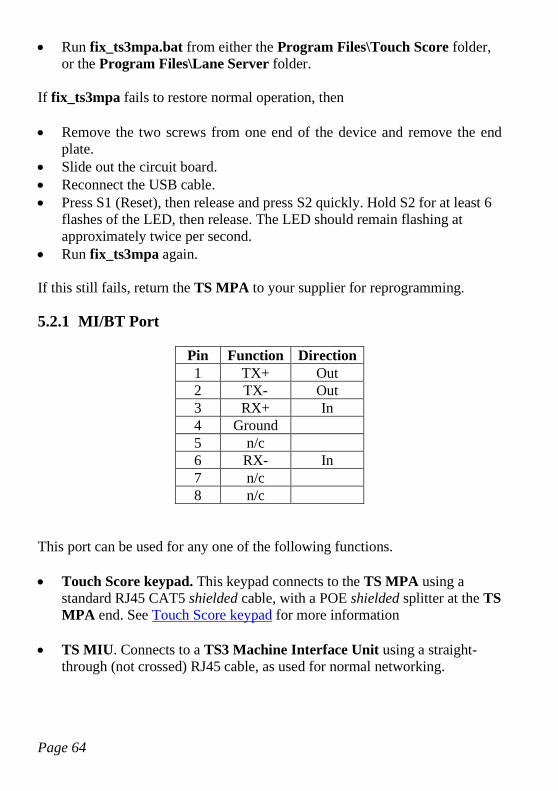
Page 64
• Run fix_ts3mpa.bat from either the Program Files\Touch Score folder,
or the Program Files\Lane Server folder.
If fix_ts3mpa fails to restore normal operation, then
• Remove the two screws from one end of the device and remove the end
plate.
• Slide out the circuit board.
• Reconnect the USB cable.
• Press S1 (Reset), then release and press S2 quickly. Hold S2 for at least 6
flashes of the LED, then release. The LED should remain flashing at
approximately twice per second.
• Run fix_ts3mpa again.
If this still fails, return the TS MPA to your supplier for reprogramming.
5.2.1 MI/BT Port
Pin Function Direction
1 TX+ Out
2 TX- Out
3 RX+ In
4 Ground
5 n/c
6 RX- In
7 n/c
8 n/c
This port can be used for any one of the following functions.
• Touch Score keypad. This keypad connects to the TS MPA using a
standard RJ45 CAT5 shielded cable, with a POE shielded splitter at the TS
MPA end. See Touch Score keypad for more information
• TS MIU. Connects to a TS3 Machine Interface Unit using a straight-
through (not crossed) RJ45 cable, as used for normal networking.
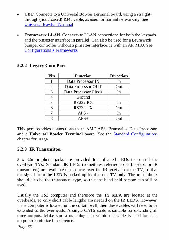
Page 65
• UBT. Connects to a Universal Bowler Terminal board, using a straight-
through (not crossed) RJ45 cable, as used for normal networking. See
Universal Bowler Terminal
• Frameworx LLAN. Connects to LLAN connections for both the keypads
and the pinsetter interface in parallel. Can also be used for a Brunswick
bumper controller without a pinsetter interface, ie with an AK MIU. See
ConfigurationsFrameworks
5.2.2 Legacy Com Port
Pin Function Direction
1 Data Processor IN In
2 Data Processor OUT Out
3 Data Processor Clock In
4 Ground
5 RS232 RX In
6 RS232 TX Out
7 APS - In
8 APS+ Out
This port provides connections to an AMF APS, Brunswick Data Processor,
and a Universal Bowler Terminal board. See the Standard Configurations
chapter for usage.
5.2.3 IR Transmitter
3 x 3.5mm phone jacks are provided for infra-red LEDs to control the
overhead TVs. Standard IR LEDs (sometimes referred to as blasters, or IR
transmitters) are available that adhere over the IR receiver on the TV, so that
the signal from the LED is picked up by that one TV only. The transmitters
should also be the transparent type, so that the hand held remote can still be
used.
Usually the TS3 computer and therefore the TS MPA are located at the
overheads, so only short cable lengths are needed on the IR LEDS. However,
if the computer is located on the curtain wall, then these cables will need to be
extended to the overheads. A single CAT5 cable is suitable for extending all
three outputs. Make sure a matching pair within the cable is used for each
output to minimize interference.
Page 66
5.3 Touch Score Machine Interface Unit
IMPORTANT SAFETY WARNING!
The Machine Interface Unit (MIU) is a low voltage, low current device and
MUST NOT be connected to mains or hazardous voltages under any
circumstances. Connect only to other SELV (safe extra low voltage, <28VAC)
circuits. All electrical work associated with this device must be carried out by
qualified persons only and be in accordance with the relevant safety codes at your
location.
• All connections to the MIU, including those from the pinspotter, must be
SELV. If the pinspotter or any other device does not provide guaranteed
SELV connections then additional isolation is required to avoid an electric
shock hazard. Maximum voltage on any circuit connected to the MIU is
28VAC. with respect to ground. Lower limits apply for some connections. See
Connection Reference for more details.
• All wiring to the MIU must be isolated both physically and electrically from
any hazardous voltages so as to ensure the connections are SELV only, as per
relevant safety codes.
• All MIU relay contact circuits must be protected by a fuse or circuit breaker
with a tripping current of 3.5 Amps or less.
• The MIU chassis MUST be securely connected to a suitable ground point.
• Power must be switched off to both the MIU and the pinspotters when
connecting or disconnecting cables.
• The terminal cover plate of the MIU must be in place when the unit is
operating or power is connected to any external device, including the
pinspotters.
• The MIU may activate and cycle the pinspotters AT ANY TIME and
WITHOUT ANY WARNING. It is therefore essential that power is
otherwise disconnected from the pinspotter before entering or working on
the pinspotter. The MIU must NEVER be relied upon to keep the pinspotter
in an unpowered or non-active state.
• Always install anti-intrusion protection to ensure that no person can
inadvertently or otherwise come in to contact with the pinspotter while it is
connected to power.
• Always install an additional manual switch or safety interlock to remove
power from the pinspotters instantly in case of emergency. Do NOT rely on
the scoring system, or front desk computer, or MIU for this function.
• Use only an approved SELV power supply for the MIU.
The TS MIU provides interconnection between the pinspotters, a pinsensing
camera, the bowler terminal and other equipment. It is required for any
installation of TS3 except those with a –
Page 67
• Magicscore/Accuscore 1 APS
• XL MIU
• AS80/90 Data Processor
• Frameworx Pinsetter Interface
• Brunswick Pinsensor board for string machines
• GSX series pinsetters
• Using the Universal MI
The TS MIU is located on the curtain wall.
The function of each LED on the MIU is listed below.
• Run. Flashes regularly to indicate that the MIU is running. Flickers when
communicating with the TS3 computer.
• Machine. Indicates the pinspotters are switched on. Slow flashing
indicates instructomat (practice) mode. Fast flashing indicates the
machines are being cycled by the MIU. Only applies to installations where
the pinspotters are controlled by the MIU.
If a safety machine shutoff has been triggered by the ball detector, or the
inactivity timeout has expired, then both the Machine and Ball Detect will
be flashing together, and the pinspotter will be switched off. See the ball
detector section for more information.
• Ball Detect. Fully On indicates that a valid ball detect signal has been
detected. If the signal is invalid (ie too fast or too slow when using speed
detectors) then the LED will flash to indicate an error. It will also flash if
configured for 2 sensors, and only one pulse has been received.
• Sweep. Indicates that the sweep switch has been activated by the sweep
leaving the home position, or the 0 degree switch opening for Brunswick
pinsetters.
• 44/144. Indicates that the 44/144 degree switch has been activated.
Brunswick pinsetters only.
Page 68
• 2nd Ball. The second ball signal is active. This is required to score 2nd
balls.
• Foul. Indicates that the foul detector has been triggered.
• Score. Indicates when a score is actually recorded. Flashing indicates that
the score has triggered a fast cycle (ie strike, 7 10 pick off in AMF
machines, extra ball in the tenth, etc)
• Bumper. The bumpers are active.
The LED functions as listed above require the MIU to be connected to a TS3
and configured with the appropriate setup. However, when it is not configured,
the following LEDS simply indicate the presence of an input signal, without
any regard to correct timing, signal polarity etc. This can be used to verify
connections during installation.
• Machine (detects RPO input)
• Ball Detect
• Sweep (also 0 degree switch)
• 44/144
• 2nd Ball
• Foul
The following sections give an overview of the connections required. See the
Connector Reference for further details.
5.3.1 Power Supply
The MIU requires a 12 VDC @ 1A regulated power supply. This power
supply needs to comply with local safety regulation for a class II device.
The MIU should be powered from the same circuit as the TS3 computer.
The camera and bowler terminal board can also be powered from the MIU
using the 12VDC AUX terminal on J17/J18 or J14. This supply is enabled
only when either lane is turned on (checked-in).
Page 69
5.3.2 Connecting to TS3
The MIU provides two ports for connection to the TS3 computer. J5 is an
RS232 port, and J6 is an RS422 port. Either may be used.
The RS232 port is primarily used when the TS3 computer is mounted adjacent
to the MIU on the curtain wall.
For all other cases, the RS422 port is preferred. It can be connected via the TS
MPA device, or to any RS422 port on the computer.
5.3.3 Pinsensing
The MIU can use either a standard video camera, or an AMF Accucam.
Video Camera
TS3 can use a standard video camera for pin detection, similar to those used in
security and monitoring systems. The following points should be noted when
choosing and installing a camera.
• The camera should be mounted on the ball return capping in such a
position, that it can “see” all ten pins on both lanes. No pin should be
completely behind any other pin. There should be space between each pin
at the neck level. In order to achieve this, the distance from the camera lens
to the back row of pins should be approximately 160inches, but this will
depend upon the distance between the lanes. Adjust the camera position to
maximise the separation between the pins.
• A 6mm lens should give a sufficiently wide angle of view.
• The height of the camera should be the same as the neck of the pins.
• The camera must be mounted securely, so that the position of the pins as
seen from the camera doesn’t change. If it is mounted on the capping, the
capping must be firmly secured.
• The camera must be suitable for the different light conditions used in the
bowling centre. Some cameras have automatic back light adjustment, some
also have automatic iris adjustment. Often just a standard inexpensive fixed
iris lens will suffice.
• The output video format of the camera must be NTSC composite video.
• The camera can be colour or black and white.
Page 70
The camera should provide an image of all 20 pins, with separation between
the pins at neck height, and with good contrast between a present pin and an
absent pin under all light conditions.
The composite video output from the camera is connected to J4. If the camera
requires 12V power, it may be powered from J3, else it will need its own
power supply.
AMF Accucam
An AMF Accucam compatible with Accuscore Plus can be used for pin
detection. The camera data cable connects to J8.
An adapter is available to allow the existing cabling from both the camera and
an Accuscore Plus bowler terminal to connect to J8.
Note that the AMF camera can NOT be powered from the TS MIU. It needs a
separate 18VAC power supply.
J8 can also be used for direct connection to a 90XL pinspotter.
5.3.4 Bowler Terminal
The TS MIU supports the following types of bowler terminal. Other types
such as Frameworx are only supported when the corresponding machine
interface system is in use, not by a TS MIU.
Touch Score Keypad.
The Touch Score keypad connects directly to J7, using a shielded RJ45 CAT5
cable. This cable provides both power and communications to the keypad.
Universal Bowler Terminal.
The UBT connects to the RS422 port of J7. Any of the keypad types
supported by the UBT may be used. J7 also provides power to the UBT.
Accuscore Plus Bowler Terminal
An Accuscore Plus terminal can be connected to either J7 or J8.
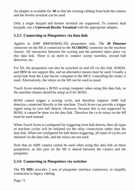
Page 71
An adapter is available for J8 so that the existing cabling from both the camera
and the bowler terminal can be used.
Only a single keypad and bowler terminal are supported. To connect dual
keypads, use a Universal Bowler Terminal with the appropriate adapter.
5.3.5 Connecting to Pinspotters via data link
Applies to AMF 8800/8290XL/Xli pinspotters only. The J8 Pinsense
connector on the MI is connected to the SCORING connector on the machine
chassis. All interaction between the scoring and the pinsetter takes place via
this data link. There is no need to connect sweep switches, second ball
detection, etc.
For Xli, the pinspotters can also be switched on and off via this link. 8290XL
and 8800 do not support this, and an alternative means must be used. Usually a
serial link from the Lane Server computer to the MCU controlling the center is
used. Alternatively, the relays on the MI can be used as usual.
Touch Score emulates a BOSS scoring computer when using this data link, so
the machine chassis should be setup as if for BOSS.
BOSS cannot trigger a scoring cycle, and therefore requires AMF ball
detectors connected directly to the machine. Touch Score can provide a trigger
signal using its own ball detects. However, because this is not supported by
BOSS, it cannot be done via the data link. Therefore the cycle relays on the MI
must be used instead.
When Touch Score is configured for triggering from ball detects, then all types
of machine cycles will be initiated via the relay connections rather than the
data link. When not configured for ball detect triggering, all types of cycles are
initiated via the data link, and the relays are not used.
Note that an AMF camera cannot be used when using this data link on these
pinspotters, as this port on the MI is shared between the camera and the
pinspotter.
5.3.6 Connecting to Pinspotters via switches
The TS MIU provides 2 sets of pinspotter interface connectors, to simplify
connection to legacy cabling.
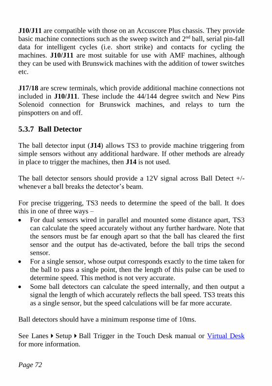
Page 72
J10/J11 are compatible with those on an Accuscore Plus chassis. They provide
basic machine connections such as the sweep switch and 2nd ball, serial pin-fall
data for intelligent cycles (i.e. short strike) and contacts for cycling the
machines. J10/J11 are most suitable for use with AMF machines, although
they can be used with Brunswick machines with the addition of tower switches
etc.
J17/18 are screw terminals, which provide additional machine connections not
included in J10/J11. These include the 44/144 degree switch and New Pins
Solenoid connection for Brunswick machines, and relays to turn the
pinspotters on and off.
5.3.7 Ball Detector
The ball detector input (J14) allows TS3 to provide machine triggering from
simple sensors without any additional hardware. If other methods are already
in place to trigger the machines, then J14 is not used.
The ball detector sensors should provide a 12V signal across Ball Detect +/-
whenever a ball breaks the detector’s beam.
For precise triggering, TS3 needs to determine the speed of the ball. It does
this in one of three ways –
• For dual sensors wired in parallel and mounted some distance apart, TS3
can calculate the speed accurately without any further hardware. Note that
the sensors must be far enough apart so that the ball has cleared the first
sensor and the output has de-activated, before the ball trips the second
sensor.
• For a single sensor, whose output corresponds exactly to the time taken for
the ball to pass a single point, then the length of this pulse can be used to
determine speed. This method is not very accurate.
• Some ball detectors can calculate the speed internally, and then output a
signal the length of which accurately reflects the ball speed. TS3 treats this
as a single sensor, but the speed calculations will be far more accurate.
Ball detectors should have a minimum response time of 10ms.
See LanesSetupBall Trigger in the Touch Desk manual or Virtual Desk
for more information.

Page 73
5.3.8 Connection Reference
See Important Safety Warning before making any connections!
J1 12VDC
Pin Function Direction
1 Ground
2 12 VDC In
J1 is used to power the MIU, and also auxiliary devices such as camera and
bowler terminals.
The power supply should be 12 VDC REGULATED. While the MI itself
requires less than 0.6 Amp, additional capacity may be required if an external
camera, bowler terminal board, ball triggers or other devices are also to be
powered from the MI. Typically a 1.5-2 Amp power supply would suffice. The
MI has an internal 2 Amp circuit breaker, so the total consumption of all
connected devices cannot exceed 2 Amps.
The power supply must also have suitable overload protection to prevent
damage to the MIU in the event of failure of the MIU or connected devices.
The MIU chassis should be connected to a local ground point.
J2 12VDC Out
J2 can be used to power auxiliary equipment such as bowler terminals or a
camera. This supply is switched off when the lane is not in use to conserve
power.
Pin Function Direction
1 Ground
2 12 VDC Out
J4 Camera
J4 is a BNC connector for composite video from a CCD camera for pin-
sensing.
If the camera requires 12VDC for power, this can be sourced from the 12VDC
AUX terminal on J2. This 12V supply is only available when either lane is
turned on (checked-in).
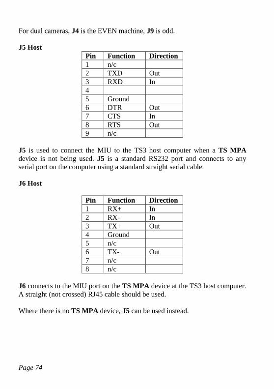
Page 74
For dual cameras, J4 is the EVEN machine, J9 is odd.
J5 Host
Pin Function Direction
1 n/c
2 TXD Out
3 RXD In
4
5 Ground
6 DTR Out
7 CTS In
8 RTS Out
9 n/c
J5 is used to connect the MIU to the TS3 host computer when a TS MPA
device is not being used. J5 is a standard RS232 port and connects to any
serial port on the computer using a standard straight serial cable.
J6 Host
Pin Function Direction
1 RX+ In
2 RX- In
3 TX+ Out
4 Ground
5 n/c
6 TX- Out
7 n/c
8 n/c
J6 connects to the MIU port on the TS MPA device at the TS3 host computer.
A straight (not crossed) RJ45 cable should be used.
Where there is no TS MPA device, J5 can be used instead.
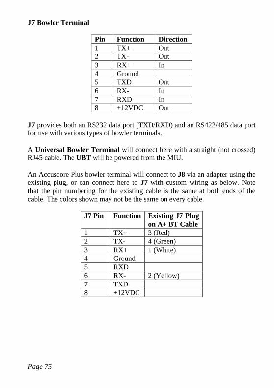
Page 75
J7 Bowler Terminal
Pin Function Direction
1 TX+ Out
2 TX- Out
3 RX+ In
4 Ground
5 TXD Out
6 RX- In
7 RXD In
8 +12VDC Out
J7 provides both an RS232 data port (TXD/RXD) and an RS422/485 data port
for use with various types of bowler terminals.
A Universal Bowler Terminal will connect here with a straight (not crossed)
RJ45 cable. The UBT will be powered from the MIU.
An Accuscore Plus bowler terminal will connect to J8 via an adapter using the
existing plug, or can connect here to J7 with custom wiring as below. Note
that the pin numbering for the existing cable is the same at both ends of the
cable. The colors shown may not be the same on every cable.
J7 Pin Function Existing J7 Plug
on A+ BT Cable
1 TX+ 3 (Red)
2 TX- 4 (Green)
3 RX+ 1 (White)
4 Ground
5 RXD
6 RX- 2 (Yellow)
7 TXD
8 +12VDC
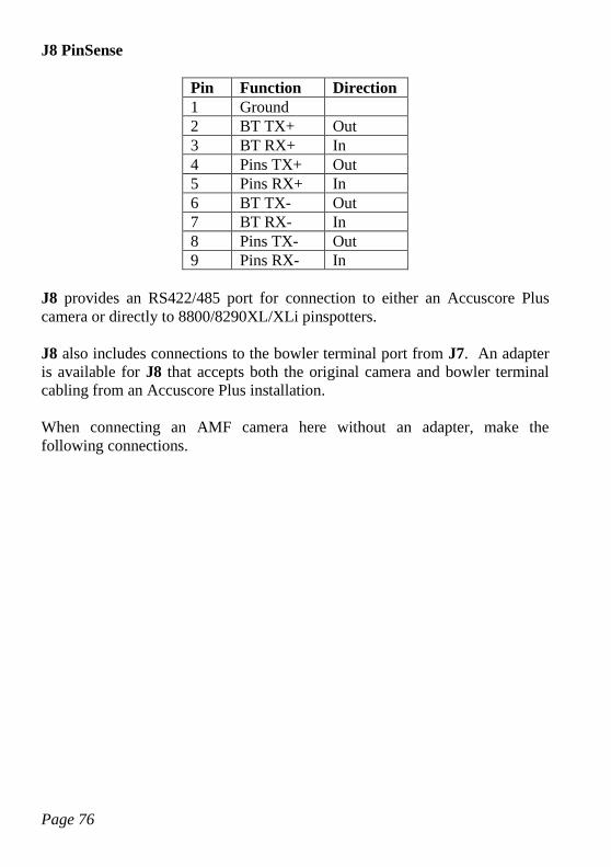
Page 76
J8 PinSense
Pin Function Direction
1 Ground
2 BT TX+ Out
3 BT RX+ In
4 Pins TX+ Out
5 Pins RX+ In
6 BT TX- Out
7 BT RX- In
8 Pins TX- Out
9 Pins RX- In
J8 provides an RS422/485 port for connection to either an Accuscore Plus
camera or directly to 8800/8290XL/XLi pinspotters.
J8 also includes connections to the bowler terminal port from J7. An adapter
is available for J8 that accepts both the original camera and bowler terminal
cabling from an Accuscore Plus installation.
When connecting an AMF camera here without an adapter, make the
following connections.
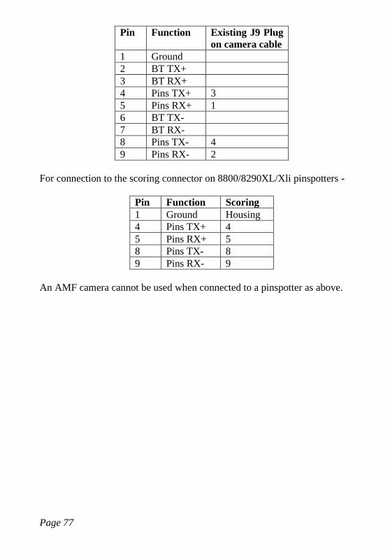
Page 77
Pin Function Existing J9 Plug
on camera cable
1 Ground
2 BT TX+
3 BT RX+
4 Pins TX+ 3
5 Pins RX+ 1
6 BT TX-
7 BT RX-
8 Pins TX- 4
9 Pins RX- 2
For connection to the scoring connector on 8800/8290XL/Xli pinspotters -
Pin Function Scoring
1 Ground Housing
4 Pins TX+ 4
5 Pins RX+ 5
8 Pins TX- 8
9 Pins RX- 9
An AMF camera cannot be used when connected to a pinspotter as above.
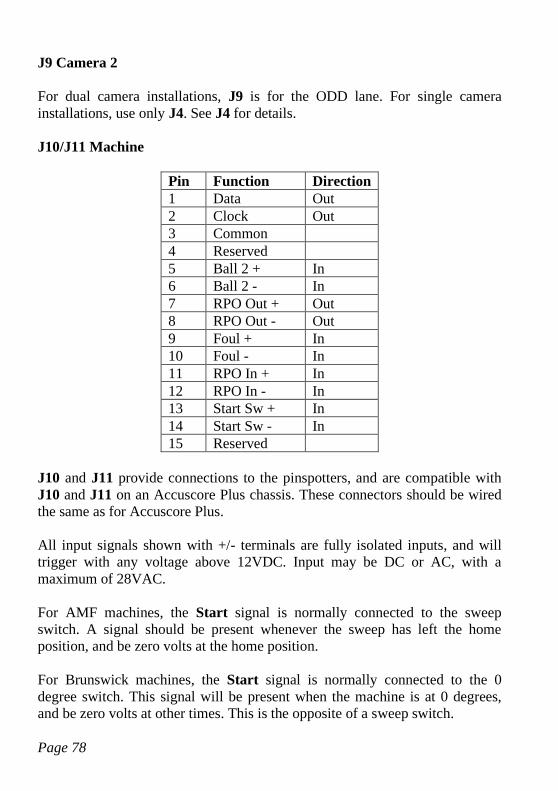
Page 78
J9 Camera 2
For dual camera installations, J9 is for the ODD lane. For single camera
installations, use only J4. See J4 for details.
J10/J11 Machine
Pin Function Direction
1 Data Out
2 Clock Out
3 Common
4 Reserved
5 Ball 2 + In
6 Ball 2 - In
7 RPO Out + Out
8 RPO Out - Out
9 Foul + In
10 Foul - In
11 RPO In + In
12 RPO In - In
13 Start Sw + In
14 Start Sw - In
15 Reserved
J10 and J11 provide connections to the pinspotters, and are compatible with
J10 and J11 on an Accuscore Plus chassis. These connectors should be wired
the same as for Accuscore Plus.
All input signals shown with +/- terminals are fully isolated inputs, and will
trigger with any voltage above 12VDC. Input may be DC or AC, with a
maximum of 28VAC.
For AMF machines, the Start signal is normally connected to the sweep
switch. A signal should be present whenever the sweep has left the home
position, and be zero volts at the home position.
For Brunswick machines, the Start signal is normally connected to the 0
degree switch. This signal will be present when the machine is at 0 degrees,
and be zero volts at other times. This is the opposite of a sweep switch.
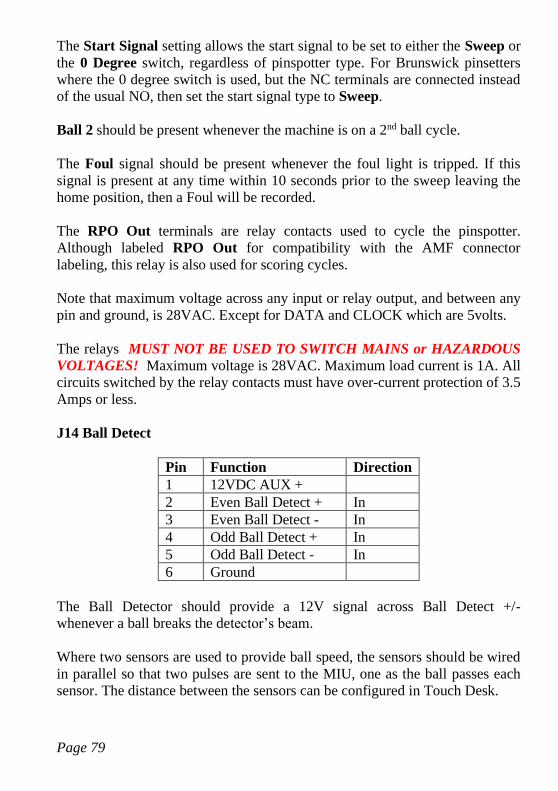
Page 79
The Start Signal setting allows the start signal to be set to either the Sweep or
the 0 Degree switch, regardless of pinspotter type. For Brunswick pinsetters
where the 0 degree switch is used, but the NC terminals are connected instead
of the usual NO, then set the start signal type to Sweep.
Ball 2 should be present whenever the machine is on a 2nd ball cycle.
The Foul signal should be present whenever the foul light is tripped. If this
signal is present at any time within 10 seconds prior to the sweep leaving the
home position, then a Foul will be recorded.
The RPO Out terminals are relay contacts used to cycle the pinspotter.
Although labeled RPO Out for compatibility with the AMF connector
labeling, this relay is also used for scoring cycles.
Note that maximum voltage across any input or relay output, and between any
pin and ground, is 28VAC. Except for DATA and CLOCK which are 5volts.
The relays MUST NOT BE USED TO SWITCH MAINS or HAZARDOUS
VOLTAGES! Maximum voltage is 28VAC. Maximum load current is 1A. All
circuits switched by the relay contacts must have over-current protection of 3.5
Amps or less.
J14 Ball Detect
Pin Function Direction
1 12VDC AUX +
2 Even Ball Detect + In
3 Even Ball Detect - In
4 Odd Ball Detect + In
5 Odd Ball Detect - In
6 Ground
The Ball Detector should provide a 12V signal across Ball Detect +/-
whenever a ball breaks the detector’s beam.
Where two sensors are used to provide ball speed, the sensors should be wired
in parallel so that two pulses are sent to the MIU, one as the ball passes each
sensor. The distance between the sensors can be configured in Touch Desk.

Page 80
The 12 VDC Aux terminal supplies 12 volts whenever either lane is on
(checked-in).
See the notes for J10/11 regarding maximum voltage and current limits.
J15 Aux
Pin Function Direction
1 Even AUX+ Out
2 Even AUX- Out
3 Odd AUX+ Out
4 Odd AUX- Out
The AUX outputs are opto-coupler outputs that can be assigned a number of
different functions. One example is to provide monitor input switching for
legacy monitor setups. Contact A.K.Microsystems for more details.
See the notes for J10/11 regarding maximum voltage and current limits.
J16 Bumpers
Pin Function Direction
1 Even Bumpers n/o Out
2 Even Bumpers n/o Out
3 Odd Bumpers n/o Out
4 Odd Bumpers n/o Out
J16 provides 2 normally open relay contacts that close when the bumpers are
to be deployed. These contacts MUST NOT BE USED TO SWITCH MAINS
or HAZARDOUS VOLTAGES! Maximum voltage is 28VAC. Maximum
load current is 1A. All circuits switched by the relay contacts must have over-
current protection of 3.5 Amps or less.
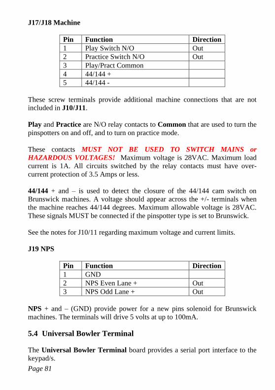
Page 81
J17/J18 Machine
Pin Function Direction
1 Play Switch N/O Out
2 Practice Switch N/O Out
3 Play/Pract Common
4 44/144 +
5 44/144 -
These screw terminals provide additional machine connections that are not
included in J10/J11.
Play and Practice are N/O relay contacts to Common that are used to turn the
pinspotters on and off, and to turn on practice mode.
These contacts MUST NOT BE USED TO SWITCH MAINS or
HAZARDOUS VOLTAGES! Maximum voltage is 28VAC. Maximum load
current is 1A. All circuits switched by the relay contacts must have over-
current protection of 3.5 Amps or less.
44/144 + and – is used to detect the closure of the 44/144 cam switch on
Brunswick machines. A voltage should appear across the +/- terminals when
the machine reaches 44/144 degrees. Maximum allowable voltage is 28VAC.
These signals MUST be connected if the pinspotter type is set to Brunswick.
See the notes for J10/11 regarding maximum voltage and current limits.
J19 NPS
Pin Function Direction
1 GND
2 NPS Even Lane + Out
3 NPS Odd Lane + Out
NPS + and – (GND) provide power for a new pins solenoid for Brunswick
machines. The terminals will drive 5 volts at up to 100mA.
5.4 Universal Bowler Terminal
The Universal Bowler Terminal board provides a serial port interface to the
keypad/s.
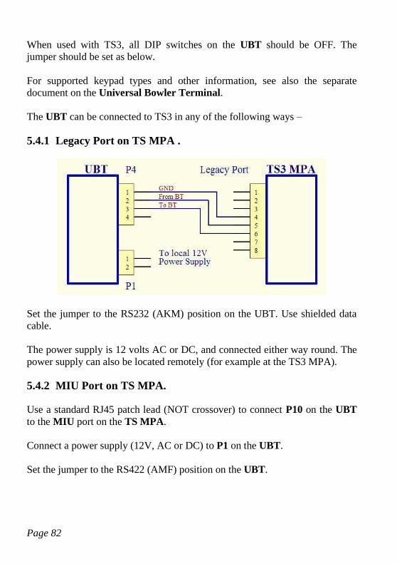
Page 82
When used with TS3, all DIP switches on the UBT should be OFF. The
jumper should be set as below.
For supported keypad types and other information, see also the separate
document on the Universal Bowler Terminal.
The UBT can be connected to TS3 in any of the following ways –
5.4.1 Legacy Port on TS MPA .
Set the jumper to the RS232 (AKM) position on the UBT. Use shielded data
cable.
The power supply is 12 volts AC or DC, and connected either way round. The
power supply can also be located remotely (for example at the TS3 MPA).
5.4.2 MIU Port on TS MPA.
Use a standard RJ45 patch lead (NOT crossover) to connect P10 on the UBT
to the MIU port on the TS MPA.
Connect a power supply (12V, AC or DC) to P1 on the UBT.
Set the jumper to the RS422 (AMF) position on the UBT.
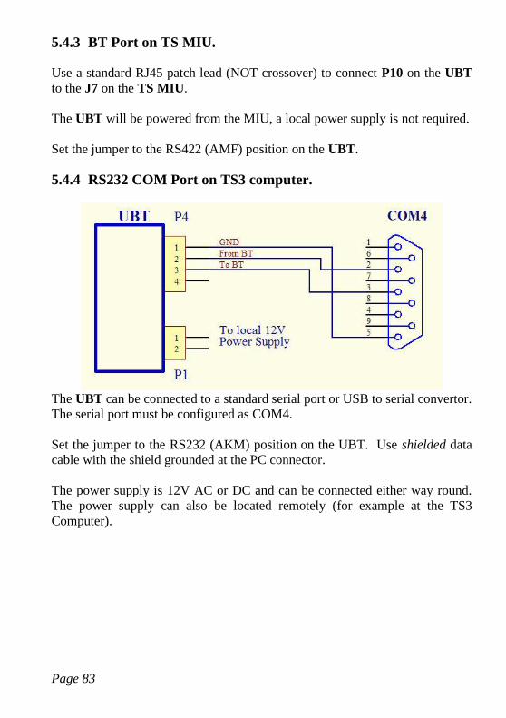
Page 83
5.4.3 BT Port on TS MIU.
Use a standard RJ45 patch lead (NOT crossover) to connect P10 on the UBT
to the J7 on the TS MIU.
The UBT will be powered from the MIU, a local power supply is not required.
Set the jumper to the RS422 (AMF) position on the UBT.
5.4.4 RS232 COM Port on TS3 computer.
The UBT can be connected to a standard serial port or USB to serial convertor.
The serial port must be configured as COM4.
Set the jumper to the RS232 (AKM) position on the UBT. Use shielded data
cable with the shield grounded at the PC connector.
The power supply is 12V AC or DC and can be connected either way round.
The power supply can also be located remotely (for example at the TS3
Computer).
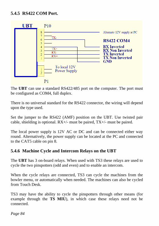
Page 84
5.4.5 RS422 COM Port.
The UBT can use a standard RS422/485 port on the computer. The port must
be configured as COM4, full duplex.
There is no universal standard for the RS422 connector, the wiring will depend
upon the type used.
Set the jumper to the RS422 (AMF) position on the UBT. Use twisted pair
cable, shielding is optional. RX+/- must be paired, TX+/- must be paired.
The local power supply is 12V AC or DC and can be connected either way
round. Alternatively, the power supply can be located at the PC and connected
to the CAT5 cable on pin 8.
5.4.6 Machine Cycle and Intercom Relays on the UBT
The UBT has 3 on-board relays. When used with TS3 these relays are used to
cycle the two pinspotters (odd and even) and to enable an intercom.
When the cycle relays are connected, TS3 can cycle the machines from the
bowler menu, or automatically when needed. The machines can also be cycled
from Touch Desk.
TS3 may have the ability to cycle the pinspotters through other means (for
example through the TS MIU), in which case these relays need not be
connected.
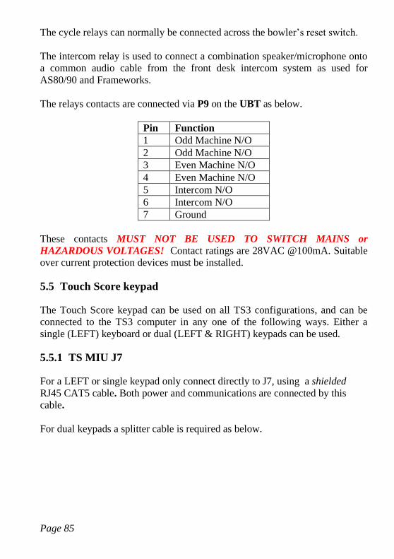
Page 85
The cycle relays can normally be connected across the bowler’s reset switch.
The intercom relay is used to connect a combination speaker/microphone onto
a common audio cable from the front desk intercom system as used for
AS80/90 and Frameworks.
The relays contacts are connected via P9 on the UBT as below.
Pin Function
1 Odd Machine N/O
2 Odd Machine N/O
3 Even Machine N/O
4 Even Machine N/O
5 Intercom N/O
6 Intercom N/O
7 Ground
These contacts MUST NOT BE USED TO SWITCH MAINS or
HAZARDOUS VOLTAGES! Contact ratings are 28VAC @100mA. Suitable
over current protection devices must be installed.
5.5 Touch Score keypad
The Touch Score keypad can be used on all TS3 configurations, and can be
connected to the TS3 computer in any one of the following ways. Either a
single (LEFT) keyboard or dual (LEFT & RIGHT) keypads can be used.
5.5.1 TS MIU J7
For a LEFT or single keypad only connect directly to J7, using a shielded
RJ45 CAT5 cable. Both power and communications are connected by this
cable.
For dual keypads a splitter cable is required as below.
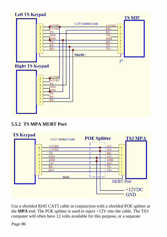
Page 86
5.5.2 TS MPA MI/BT Port
Use a shielded RJ45 CAT5 cable in conjunction with a shielded POE splitter at
the MPA end. The POE splitter is used to inject +12V into the cable. The TS3
computer will often have 12 volts available for this purpose, or a separate
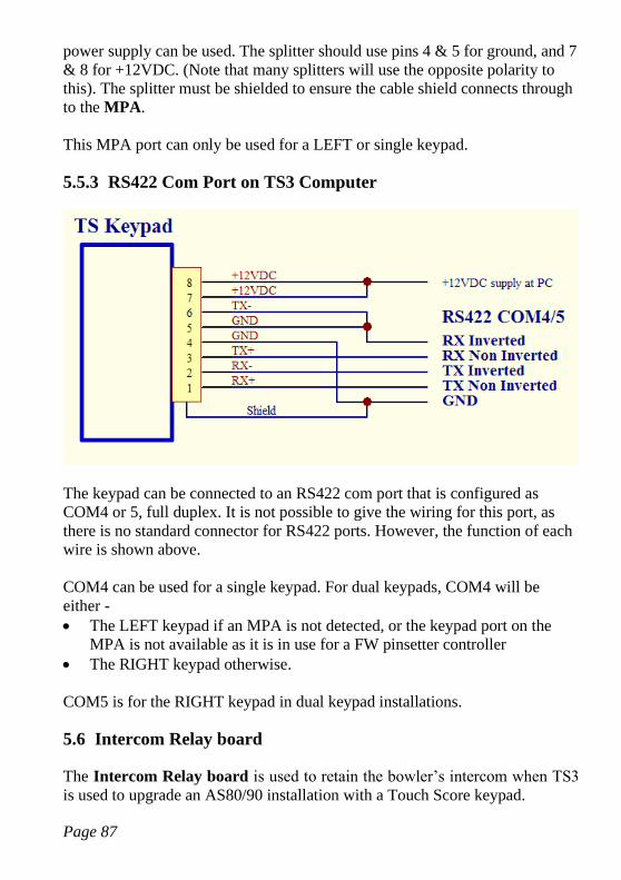
Page 87
power supply can be used. The splitter should use pins 4 & 5 for ground, and 7
& 8 for +12VDC. (Note that many splitters will use the opposite polarity to
this). The splitter must be shielded to ensure the cable shield connects through
to the MPA.
This MPA port can only be used for a LEFT or single keypad.
5.5.3 RS422 Com Port on TS3 Computer
The keypad can be connected to an RS422 com port that is configured as
COM4 or 5, full duplex. It is not possible to give the wiring for this port, as
there is no standard connector for RS422 ports. However, the function of each
wire is shown above.
COM4 can be used for a single keypad. For dual keypads, COM4 will be
either -
• The LEFT keypad if an MPA is not detected, or the keypad port on the
MPA is not available as it is in use for a FW pinsetter controller
• The RIGHT keypad otherwise.
COM5 is for the RIGHT keypad in dual keypad installations.
5.6 Intercom Relay board
The Intercom Relay board is used to retain the bowler’s intercom when TS3
is used to upgrade an AS80/90 installation with a Touch Score keypad.
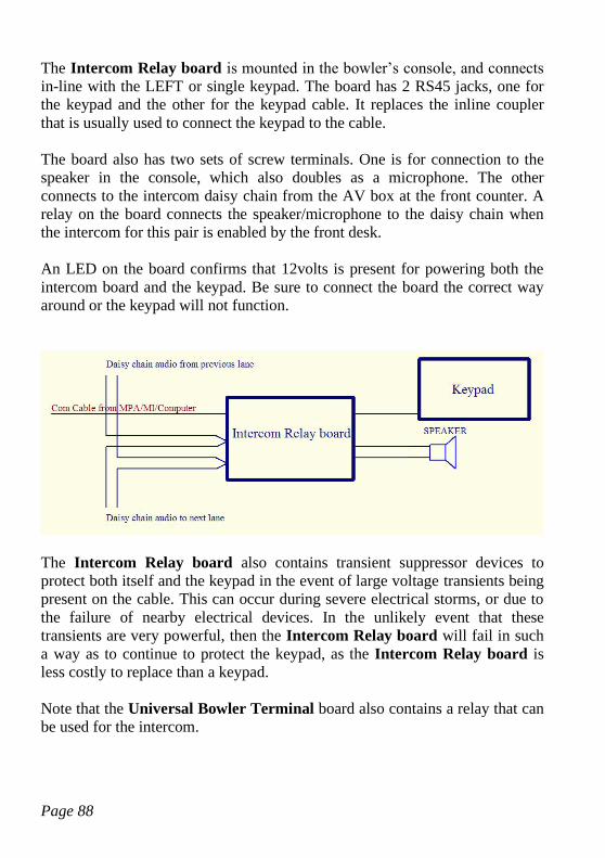
Page 88
The Intercom Relay board is mounted in the bowler’s console, and connects
in-line with the LEFT or single keypad. The board has 2 RS45 jacks, one for
the keypad and the other for the keypad cable. It replaces the inline coupler
that is usually used to connect the keypad to the cable.
The board also has two sets of screw terminals. One is for connection to the
speaker in the console, which also doubles as a microphone. The other
connects to the intercom daisy chain from the AV box at the front counter. A
relay on the board connects the speaker/microphone to the daisy chain when
the intercom for this pair is enabled by the front desk.
An LED on the board confirms that 12volts is present for powering both the
intercom board and the keypad. Be sure to connect the board the correct way
around or the keypad will not function.
The Intercom Relay board also contains transient suppressor devices to
protect both itself and the keypad in the event of large voltage transients being
present on the cable. This can occur during severe electrical storms, or due to
the failure of nearby electrical devices. In the unlikely event that these
transients are very powerful, then the Intercom Relay board will fail in such
a way as to continue to protect the keypad, as the Intercom Relay board is
less costly to replace than a keypad.
Note that the Universal Bowler Terminal board also contains a relay that can
be used for the intercom.
Page 89
5.7 Adam Data Acquisition Modules for String Pinsetters.
Adam Data Acquisition modules can be used to interface TS3 with string
pinsetters that have mechanical switches to determine the pinfall.
The modules required are –
Adam 4068/9 Relay output module. One module required per pair. Provides
two relays per lane as below –
• Power Relay - Controls power to the pinspotter.
• Set Relay - Sets a full deck by cycling the pinspotter whenever pins are
left standing at the end of a frame.
This relay module is optional and may be omitted if neither of the above
functions are required.
The 4069 is a heavy-duty version of the 4068. Electrical requirements of the
specific pinsetter will determine the required type.
Adam 4051 Digital Input module. For 9 or 10 pin machines, two modules are
required.
For 5 pin machines, one module per pair is required. However, if this is not
practical (for example if the machines do not share a common ground) then
two modules may be used as per the 9/10 pin case. Set the MI type to Adam
9/10 pin in this instance.
Inputs supported are –
• Pin Switches (up to 10 per lane)
• Ball Detector Input (1 per lane)
• Foul Detector Input (1 per lane)
• Cycle Input
A ball detector is required and must provide a signal of at least 500ms
regardless of ball speed. Ball speed detection is not supported.
The pin switches will be read at the expiry of the ball detect timeout after the
ball detect has been triggered, or immediately if a cycle signal is received
Page 90
during this period. An active signal on the pin inputs indicates that the
corresponding pin is left standing.
The cycle input is used to detect that the machine has cycled due to one or
more pins being knocked down. The presence of this signal during the ball
detect timeout period will cause an instant read of the pins. If all pin inputs are
high (all standing) this will be interpreted as a strike or spare rather than a
miss. The machine is not expected to cycle if no pins have been hit, therefore
all pins standing indicates a reset and therefore a strike or spare has occurred.
Only the ball detect delay in setup is used. All other machine settings are
ignored.
All Adam modules must be connected to a shared two wire (half duplex)
RS485 port on the TS3 computer. This port must be configured as COM6.
See the ADAM documentation for electrical specifications of the I/O
connections. If the machine signals are not within the specifications of the
ADAM device, for example AC voltages are used, then additional components
such as diodes may be required.
Prior to use, each Adam module must be configured using the software
supplied with the module. See the Adam manuals for more information.
The required configuration parameters are –
Baud Rate = 9600
Checksum = Enabled
Protocol = Advantech (if available to be set)
The 4068/9 output module must be set to ID=1.
The 4051 input module(s) are then set to IDs 2 (odd lane) and 3 (even lane)
5.7.1 Function List
Below is a list of each I/O port on the modules and their function.
This document does not provide details on how to connect each port to the
pinspotters, as requirements will vary widely from machine to machine. The
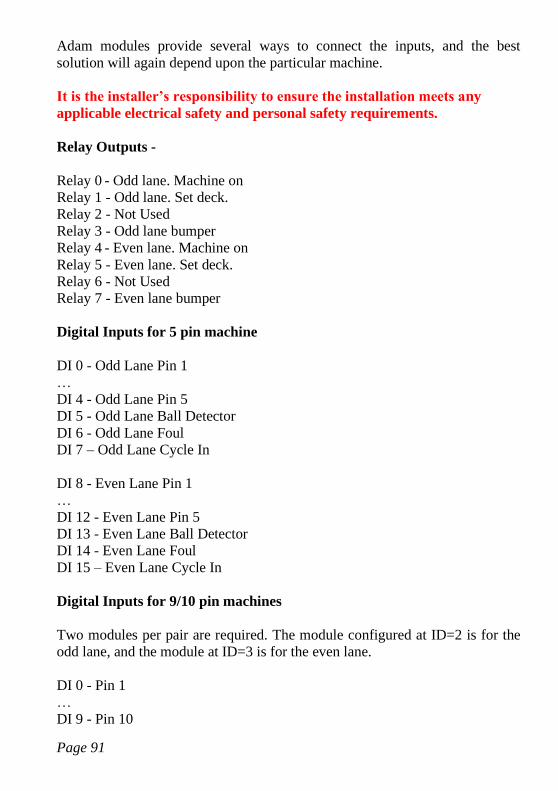
Page 91
Adam modules provide several ways to connect the inputs, and the best
solution will again depend upon the particular machine.
It is the installer’s responsibility to ensure the installation meets any
applicable electrical safety and personal safety requirements.
Relay Outputs -
Relay 0 - Odd lane. Machine on
Relay 1 - Odd lane. Set deck.
Relay 2 - Not Used
Relay 3 - Odd lane bumper
Relay 4 - Even lane. Machine on
Relay 5 - Even lane. Set deck.
Relay 6 - Not Used
Relay 7 - Even lane bumper
Digital Inputs for 5 pin machine
DI 0 - Odd Lane Pin 1
…
DI 4 - Odd Lane Pin 5
DI 5 - Odd Lane Ball Detector
DI 6 - Odd Lane Foul
DI 7 – Odd Lane Cycle In
DI 8 - Even Lane Pin 1
…
DI 12 - Even Lane Pin 5
DI 13 - Even Lane Ball Detector
DI 14 - Even Lane Foul
DI 15 – Even Lane Cycle In
Digital Inputs for 9/10 pin machines
Two modules per pair are required. The module configured at ID=2 is for the
odd lane, and the module at ID=3 is for the even lane.
DI 0 - Pin 1
…
DI 9 - Pin 10

Page 92
DI 10 - Ball Detector
DI 11 - Foul
DI 12 – Cycle In
D13-15 - Not Used
Page 93
5.8 Universal MI
IMPORTANT SAFETY WARNING!
The devices described here are low voltage, low current devices and MUST NOT
be connected to mains or hazardous voltages under any circumstances. Connect
only to other SELV (safe extra low voltage, <28VAC) circuits. All electrical work
associated with this device must be carried out by qualified persons only and be
in accordance with the relevant safety codes at your location and the
manufacturer’s instructions.
• This equipment may activate and cycle the pinspotters AT ANY TIME and
WITHOUT ANY WARNING. It is therefore essential that power is
otherwise disconnected from the pinspotter before entering or working on
the pinspotter. This equipment must NEVER be relied upon to keep the
pinspotter in an unpowered or non-active state.
• Always install anti-intrusion protection to ensure that no person can
inadvertently or otherwise come in to contact with the pinspotter while it is
connected to power.
• Always install an additional manual switch or safety interlock to remove
power from the pinspotters instantly in case of emergency. Do NOT rely on
the scoring system, or front desk computer, or the devices described here for
this function.
• It is the installer’s responsibility to ensure the installation meets any
applicable electrical safety and personal safety requirements.
The Universal MI is built in to the TS3 software, and uses mostly general
purpose I/O modules (GPIO) to connect to a wide range of pinspotting
equipment. It offers similar functionality to the TS MIU.
It can be used with an IP (network connected) camera, or an AMF A+
Accucam.
When used with an IP camera, the Universal MI can use visual clues to
determine the state of the machine and therefore record the score without any
physical connection to the pinspotter. The addition of GPIO modules provides
further functionality such as triggering and controlling the pinspotter
(on/off/cycle/respot etc)
All the devices described here (Adam Modules, MI-X, AMF-X can be
mounted inside a standard din-rail enclosure for a tidy installation. It is
Page 94
recommended that an external power supply be used, rather than bringing
mains voltages into the enclosure.
AMF 90XL pinspotters can be connected directly to an RS422 port on TS3
configured as COM10. In this configuration, the state of the machine is read
via this interface, and neither visual detection nor GPIO is required. The
exception to this is if TS3 is used to trigger the pinspotter, when Ball Detect
inputs and cycle output relays are required.
Most of the setup options available with a normal TS MIU are also available
with the Universal MI.
In addition, the Universal MI supports using an IP camera for string
pinsetters, by setting the pinsetter type to Generic String. An IP camera is
used for detecting pins. A ball detect input is required to trigger the score. The
cycle output is used to reset a full deck when needed. A Foul input may also be
connected. Other options are not compatible with Generic Strings.
See the Universal MI Tab and Camera Setup for setup options and more
information.
5.8.1 Camera
The Universal MI requires either –
• A network camera that supports MJPEG over HTTP. See Universal MI
Tab for supported types and URLs
• An AMF Accuscore Plus camera on COM11, RS422 required.
The network camera should ideally be connected only to its TS3 computer on
a separate network adapter and subnet from the main network.
For IP Cameras, diagnostic images can be found in the Camera\Score 0 and 1
folders. Score 0 is for the odd lane, Score 1 is for the even lane. Files are
named according to where the arrows were at the time as follows –
Lll_Gg_Pp_Bbb_XXX.bmp
ll is the lane of the arrow (0 =even, 1=odd)
g is the game number
p is the player number
bb is the ball number
Page 95
XXX is one of –
SCR Ball was scored from this image
SWP Sweep or Start switch change detected
RPO Non scoring cycle
5.8.2 Input Module
Where hardwired inputs are required, an ADAM 4052 input module is
connected to a shared two wire (half duplex) RS485 port on the TS3 computer.
This port must be configured as COM12.
Prior to use, the Adam module must be configured using the software supplied
with the module. See the Adam manuals for more information.
The required configuration parameters are –
Baud Rate = 9600
Checksum = Enabled
Protocol = Advantech (if available to be set)
The 4502 must be set to ID=2.
The inputs on the module are detailed below. See the Universal MI Tab to
enable each input.
D0 – Odd Lane Sweep/0 Degree switch
D1 – Even Lane Sweep/0 Degree switch
D2 – Odd Lane 2nd Ball
D3 – Even Lane 2nd Ball
D4 – Odd Lane Foul or 44/144
D5 – Even Lane Foul or 44/144
D6 – Odd Lane Ball Detect or RPO In or 44/144
D7 – Even Lane Ball Detect or RPO In or 44/144
Note that D0-D5 are fully isolated inputs with both + and – connections.
However D6 and D7 share a single common. This is not usually a problem
with ball detectors, but may require additional wiring or relays when used for
RPO In or 44/144 switch.
See the ADAM documentation for electrical specifications of the connections.
If the signal voltages are not within the specifications of the ADAM device,
Page 96
for example AC voltages are used, then additional components such as diodes
may be required.
The Ball Detector and RPO In share the D6/7 and therefore cannot be used
together on the one device. Generally both are not required.
If a ball detector is connected, then the MI can automatically determine if the
current cycle is a scoring cycle or not, by noting whether a ball has passed.
Without a ball detector, it is necessary to connect this input to any external
cycle switches that are intended to initiate an RPO or non scoring cycle. Even
when TS3 is not initiating the cycle (no relays connected) this input is still
necessary to prevent a score being recorded on that cycle.
Note that this Ball Detector input is NOT speed sensitive and cannot be used
for ball speed display. There must be a valid signal for at least 500ms
whenever a ball passes, regardless of ball speed. This will require a detector
with a programmable OFF DELAY, or a delay circuit will need to be added.
Minimum response time of the detector should be 10mS. See MI-X below for
if ball speed detection is required.
The 44/144 switch will be on D4/5 if Foul is not enabled else it will be on
D6/7. If both 44/144 and Foul are enabled then neither Ball Detect nor RPO
In can be used. Foul can often be easily triggered visually, in which case a
wired connection is not needed.
5.8.3 Output Module
Where hardwired outputs are required, an ADAM 4068 or 4069 relay module
can be setup and connected in the same way as for the input module above.
The relay module must be set to ID=1.
The relay module must be enabled in Universal MI Tab.
Each output is listed below.
RL0 – Odd Lane Pinspotter On
RL1 – Even Lane Pinspotter On
RL2 – Odd Lane Instructomat/NPS
RL3 – Even Lane Instructomat/NPS
RL4 – Odd Lane Cycle Pinspotter
Page 97
RL5 – Even Lane Cycle Pinspotter
RL6 – Odd Lane Bumpers
RL7 – Even Lane Bumpers
The function of RL2 and RL3 depends upon the type of pinspotter selected.
Instructomat is only available on AMF, whereas the New Pins Solenoid is
only used for Brunswick.
See the ADAM documentation for electrical specification of the connections.
5.8.4 Ball Speed Detector
This module is used to read the ball speed from a suitable detector. In order to
coexist on the comline with Adam modules, it uses the same protocol as an
Adam 4053. It is intended for use by custom hardware rather than an actual
Adam 4053.
The 16 bits of data read from this module represent the ball speed in 1/10ths of
a MPH.
Note that this input alone cannot be used to trigger a ball detected signal. A
valid signal is still required either from a GPIO input or from a visual
detection. Upon receipt of this signal, Touch Score will read the Ball Speed
Detector for speed information.
The Ball Detector uses ID=5/6 for the odd/even lane.
See the Adam 4053 documentation for protocol information.
5.8.5 Pinfall Output Module
This module outputs pinfall data after each cycle to allow the machines to
intelligently react to the last pinfall.
In order to coexist on the comline with Adam modules, it uses the same
protocol as an Adam 4056. It is intended for use by custom hardware rather
than an actual Adam 4056.
The 10 lower bits of the 16 bits of data output represent the pins. A 1
represents that the pin is still standing.
Page 98
The Pinfall Output module uses ID=3/4 for the odd/even lane.
See the Adam 4056 documentation for protocol information.
5.8.6 MI-X
There are two functions that are not available with GPIO modules, and require
additional specialist hardware -
• Pinfall data for fast cycles on AMF 82-70s with MP expanders
• Ball Speed detection from suitable ball detectors (see TS MIU)
The MI-X (MI Extender) provides both these functions. For AMF pinfall data
only, see also the AMF-X.
In addition, the MI-X provides the following outputs –
• Relays to cycle the pinspotters on each lane.
• NPS outputs for the New Pins Solenoid on Brunswick machines.
These extra functions allow the MI-X to be the only device required (no Adam
modules) in many cases, including providing machine triggering. In particular
where the following conditions can be met -
• Start, 2nd Ball, and Foul signals can all be detected visually, or derived
from an XL90 pinspotter.
• There are no bumpers, or there is a FW bumper controller for the
bumpers.
• Pinspotter On/Off control can be provided by a central controller on
the lane server, or is not required.
Note that the Ball Detector input can be used for RPO In instead. See the
Input Module section for details on why only one of these signals is ever
required (not both).
The MI-X connects to the same two wire serial interface as the Adam modules
on COM12.
The MI-X requires both 12V and 3.3 Volts power supplies. As the MIX is
usually used with Adam modules which require 12V, then only an additional
12V-3.3V din rail mounted supply is required.
Page 99
Note that maximum allowed voltage across any input or relay output, and
between any pin and ground, is 28VAC. Except for DATA, CLOCK and NPS
which are 5volts.
The relays MUST NOT BE USED TO SWITCH MAINS or HAZARDOUS
VOLTAGES! Maximum voltage is 28VAC. Maximum load current is 1A. All
circuits switched by the relay contacts must have over-current protection of 3.5
Amps or less. If contacts with a higher rating are required, then an additional
DIN mounted relay should be added.
5.8.6.1 Jumpers
There are two jumper positions inside the MI-X. Neither should be present
during normal use.
JP1 – initiates self test mode
JP1&JP2 – initiates self recovery mode.
5.8.6.2 LEDs
There are two LEDs on the Ethernet connector.
The yellow LED indicates the Ethernet link is connected.
The green LED will –
Flash once every second once the MI-X software has initialized.
Flash quickly to indicate activity on the Ethernet connection.
Flash quickly to indicate activity on the serial connection.
During normal use while connected to TS3, the green LED should be flashing
quickly.
5.8.6.3 J1 Ethernet
The Ethernet connection is presently only used for programming the device.
5.8.6.4 J2 Power & Comms
The MI-X requires a two supply voltages, 3.3V & 1A for the processor, and
12V @ 0.5A for I/O. Connect to pins 3,4 & 5 as shown.
The MI-X communicates with TS3 via an RS485 half duplex com port. Use
D+, D- and Ground to connect to the com port.
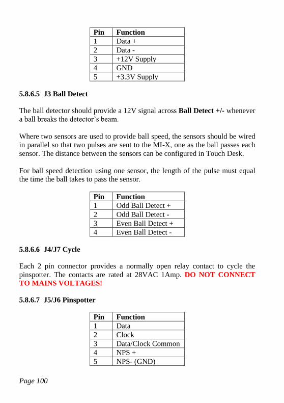
Page 100
Pin Function
1 Data +
2 Data -
3 +12V Supply
4 GND
5 +3.3V Supply
5.8.6.5 J3 Ball Detect
The ball detector should provide a 12V signal across Ball Detect +/- whenever
a ball breaks the detector’s beam.
Where two sensors are used to provide ball speed, the sensors should be wired
in parallel so that two pulses are sent to the MI-X, one as the ball passes each
sensor. The distance between the sensors can be configured in Touch Desk.
For ball speed detection using one sensor, the length of the pulse must equal
the time the ball takes to pass the sensor.
Pin Function
1 Odd Ball Detect +
2 Odd Ball Detect -
3 Even Ball Detect +
4 Even Ball Detect -
5.8.6.6 J4/J7 Cycle
Each 2 pin connector provides a normally open relay contact to cycle the
pinspotter. The contacts are rated at 28VAC 1Amp. DO NOT CONNECT
TO MAINS VOLTAGES!
5.8.6.7 J5/J6 Pinspotter
Pin Function
1 Data
2 Clock
3 Data/Clock Common
4 NPS +
5 NPS- (GND)
Page 101
These connectors provide either the data/clock/common signals needed for
intelligent cycles on AMF 8270 type pinspotters, or a 5V output used to drive
the New Pins Solenoid relay for Brunswick pinspotters.
Note that the 5V output is NOT isolated and maximum current is 100mA. It is
intended to drive an NPS relay as per Brunswick CCD processor boards, not
the NPS directly.
5.8.7 AMF-X
There are two functions that are not available with GPIO modules, and require
additional specialist hardware -
• Pinfall data for fast cycles on AMF 82-70s with MP expanders
• Ball Speed detection from suitable ball detectors (see TS MIU)
The AMF-X (AMF Extender) provides the pinfall data for AMF machines
only.
See MI-X for both AMF pinfall and ball speed detection.
The AMF-X connects to the TS computer using a USB to RS232 convertor set
to COM18. The convertor requires extra functionality compared with a
standard RS232 port –
• The recommended device is part number Chipi-X10 from FTDI, although
other devices based on the same or later chipsets from FTDI may be
suitable. Note that some older chipsets from FTDI have known problems
with clocking and may not work.
• The FTDI D2XX device driver must be installed.
• The device must include hardware handshaking lines as well as TXD &
RXD.
The connections to the AMF-X are described below.
5.8.7.1 J1 Host
J1 connects to the UT232R-200 device.
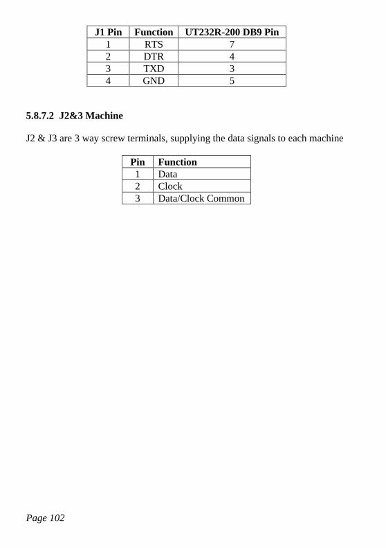
Page 102
J1 Pin Function UT232R-200 DB9 Pin
1 RTS 7
2 DTR 4
3 TXD 3
4 GND 5
5.8.7.2 J2&3 Machine
J2 & J3 are 3 way screw terminals, supplying the data signals to each machine
Pin Function
1 Data
2 Clock
3 Data/Clock Common
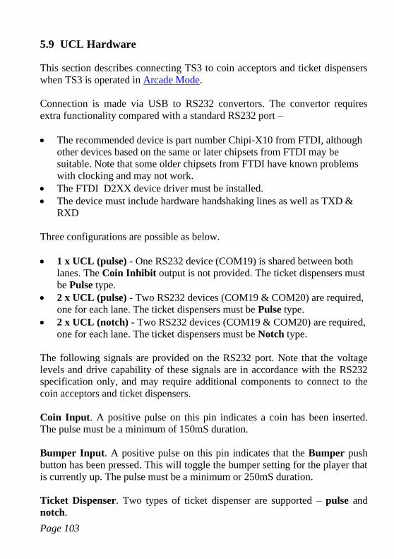
Page 103
5.9 UCL Hardware
This section describes connecting TS3 to coin acceptors and ticket dispensers
when TS3 is operated in Arcade Mode.
Connection is made via USB to RS232 convertors. The convertor requires
extra functionality compared with a standard RS232 port –
• The recommended device is part number Chipi-X10 from FTDI, although
other devices based on the same or later chipsets from FTDI may be
suitable. Note that some older chipsets from FTDI have known problems
with clocking and may not work.
• The FTDI D2XX device driver must be installed.
• The device must include hardware handshaking lines as well as TXD &
RXD
Three configurations are possible as below.
• 1 x UCL (pulse) - One RS232 device (COM19) is shared between both
lanes. The Coin Inhibit output is not provided. The ticket dispensers must
be Pulse type.
• 2 x UCL (pulse) - Two RS232 devices (COM19 & COM20) are required,
one for each lane. The ticket dispensers must be Pulse type.
• 2 x UCL (notch) - Two RS232 devices (COM19 & COM20) are required,
one for each lane. The ticket dispensers must be Notch type.
The following signals are provided on the RS232 port. Note that the voltage
levels and drive capability of these signals are in accordance with the RS232
specification only, and may require additional components to connect to the
coin acceptors and ticket dispensers.
Coin Input. A positive pulse on this pin indicates a coin has been inserted.
The pulse must be a minimum of 150mS duration.
Bumper Input. A positive pulse on this pin indicates that the Bumper push
button has been pressed. This will toggle the bumper setting for the player that
is currently up. The pulse must be a minimum or 250mS duration.
Ticket Dispenser. Two types of ticket dispenser are supported – pulse and
notch.
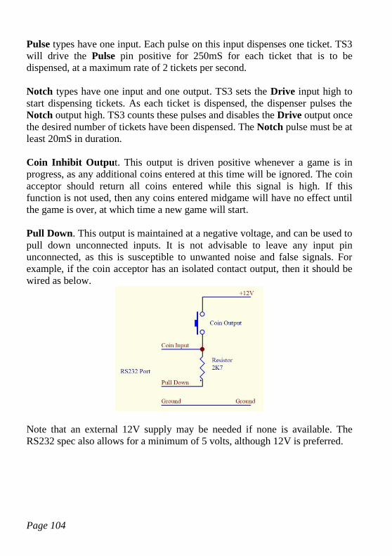
Page 104
Pulse types have one input. Each pulse on this input dispenses one ticket. TS3
will drive the Pulse pin positive for 250mS for each ticket that is to be
dispensed, at a maximum rate of 2 tickets per second.
Notch types have one input and one output. TS3 sets the Drive input high to
start dispensing tickets. As each ticket is dispensed, the dispenser pulses the
Notch output high. TS3 counts these pulses and disables the Drive output once
the desired number of tickets have been dispensed. The Notch pulse must be at
least 20mS in duration.
Coin Inhibit Output. This output is driven positive whenever a game is in
progress, as any additional coins entered at this time will be ignored. The coin
acceptor should return all coins entered while this signal is high. If this
function is not used, then any coins entered midgame will have no effect until
the game is over, at which time a new game will start.
Pull Down. This output is maintained at a negative voltage, and can be used to
pull down unconnected inputs. It is not advisable to leave any input pin
unconnected, as this is susceptible to unwanted noise and false signals. For
example, if the coin acceptor has an isolated contact output, then it should be
wired as below.
Note that an external 12V supply may be needed if none is available. The
RS232 spec also allows for a minimum of 5 volts, although 12V is preferred.
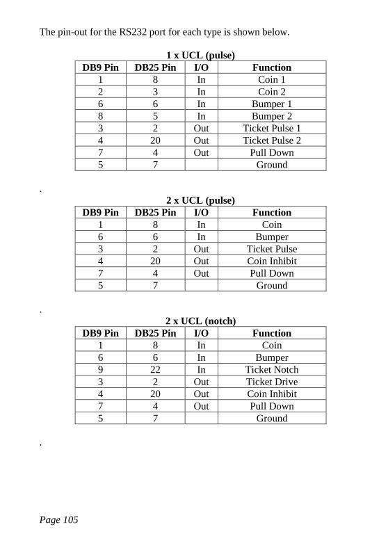
Page 105
The pin-out for the RS232 port for each type is shown below.
1 x UCL (pulse)
DB9 Pin DB25 Pin I/O Function
1 8 In Coin 1
2 3 In Coin 2
6 6 In Bumper 1
8 5 In Bumper 2
3 2 Out Ticket Pulse 1
4 20 Out Ticket Pulse 2
7 4 Out Pull Down
5 7 Ground
.
2 x UCL (pulse)
DB9 Pin DB25 Pin I/O Function
1 8 In Coin
6 6 In Bumper
3 2 Out Ticket Pulse
4 20 Out Coin Inhibit
7 4 Out Pull Down
5 7 Ground
.
2 x UCL (notch)
DB9 Pin DB25 Pin I/O Function
1 8 In Coin
6 6 In Bumper
9 22 In Ticket Notch
3 2 Out Ticket Drive
4 20 Out Coin Inhibit
7 4 Out Pull Down
5 7 Ground
.


![One Touch of Venus - Kurt Weill [Score]](https://img.pdfslide.net/doc/110x75/563dbade550346aa9aa8bc34/one-touch-of-venus-kurt-weill-score.jpg)