Embed Size (px)
Citation preview
Toward a Survivability/Lethality Analysis Directorate
(SLAD) Methodology for Conducting
System of Systems Analysis (SoSA)
by Jeffrey A. Smith and Michael W. Starks
ARL-TR-5555 June 2011
Approved for public release; distribution is unlimited
NOTICES
Disclaimers
The findings in this report are not to be construed as an official Department of the Army position
unless so designated by other authorized documents.
Citation of manufacturer’s or trade names does not constitute an official endorsement or
approval of the use thereof.
Destroy this report when it is no longer needed. Do not return it to the originator.
Army Research Laboratory White Sands Missile Range, NM 88002-5513
ARL-TR-5555 June 2011
Toward a Survivability/Lethality Analysis Directorate
(SLAD) Methodology for Conducting
System of Systems Analysis (SoSA)
Jeffrey A. Smith and Michael W. Starks
Survivability/Lethality Analysis Directorate, ARL
Approved for public release; distribution is unlimited.
ii
REPORT DOCUMENTATION PAGE Form Approved OMB No. 0704-0188
Public reporting burden for this collection of information is estimated to average 1 hour per response, including the time for reviewing instructions, searching existing data sources, gathering and maintaining the data needed, and completing and reviewing the collection information. Send comments regarding this burden estimate or any other aspect of this collection of information, including suggestions for reducing the burden, to Department of Defense, Washington Headquarters Services, Directorate for Information Operations and Reports (0704-0188), 1215 Jefferson Davis Highway, Suite 1204, Arlington, VA 22202-4302. Respondents should be aware that notwithstanding any other provision of law, no person shall be subject to any penalty for failing to comply with a collection of information if it does not display a currently valid OMB control number.
PLEASE DO NOT RETURN YOUR FORM TO THE ABOVE ADDRESS.
1. REPORT DATE (DD-MM-YYYY)
June 2011
2. REPORT TYPE
Final
3. DATES COVERED (From - To)
10/01/10–03/31/11 4. TITLE AND SUBTITLE
Toward a Survivability/Lethality Analysis Directorate (SLAD) Methodology for
Conducting System of Systems Analysis (SoSA)
5a. CONTRACT NUMBER
5b. GRANT NUMBER
5c. PROGRAM ELEMENT NUMBER
6. AUTHOR(S)
Jeffrey A. Smith, Michael W. Starks
5d. PROJECT NUMBER
5e. TASK NUMBER
5f. WORK UNIT NUMBER
7. PERFORMING ORGANIZATION NAME(S) AND ADDRESS(ES)
U.S. Army Research Laboratory
Information and Electronic Protection Division
Survivability/Lethality Analysis Directorate (ATTN: RDRL-SLE/RDRL-SL)
White Sands Missile Range, NM 88002-5513
8. PERFORMING ORGANIZATION REPORT NUMBER
ARL-TR-5555
9. SPONSORING/MONITORING AGENCY NAME(S) AND ADDRESS(ES)
U.S. Army Research Laboratory
2800 Powder Mill Road
Adelphi, MD 20783-1145
10. SPONSOR/MONITOR’S ACRONYM(S)
11. SPONSOR/MONITOR'S REPORT
NUMBER(S)
12. DISTRIBUTION/AVAILABILITY STATEMENT
Approved for public release; distribution is unlimited.
13. SUPPLEMENTARY NOTES
14. ABSTRACT
The Survivability/Lethality Analysis Directorate (SLAD) of the U.S. Army Research Laboratory (ARL) provides survivability,
lethality, and vulnerability analyses and expert technical consultation on survivability matters. Traditionally, these analyses
focused on single items analyzed in isolation; while still important, this focus is insufficient to address the current needs of
SLAD’s most important customers including U.S. Army Test and Evaluation command (ATEC) and Program Executive
Offices (PEOs) Program Managers (PMs). In order to enable the required force operating capabilities, Army leadership is
defining and developing complex system of systems (SoS) suites of technologies called ―capability packages.‖ This report
documents how we are analyzing technologies and capability packages in a mission based SoS context. 15. SUBJECT TERMS
system of systems; SoS, SoSA, system of systems analysis
16. SECURITY CLASSIFICATION OF: 17. LIMITATION
OF ABSTRACT
UU
18. NUMBER
OF PAGES
38
19a. NAME OF RESPONSIBLE PERSON
Jeffrey A. Smith a. REPORT
Unclassified
b. ABSTRACT
Unclassified
c. THIS PAGE
Unclassified
19b. TELEPHONE NUMBER (Include area code)
(575) 678-1332
Standard Form 298 (Rev. 8/98)
Prescribed by ANSI Std. Z39.18
iii
Contents
List of Figures v
List of Tables v
Acknowledgments vi
1. Introduction 1
2. Use Cases for SoSA Application 2
3. Methodology 5
3.1 Phase 1: Define the Problem ..........................................................................................5
3.1.1 Identify the Objective(s) ......................................................................................6
3.1.2 Identify the Issues ................................................................................................6
3.1.3 Experimental Directive ........................................................................................7
3.1.4 An Example Showing Phase 1 in Execution .......................................................8
3.2 Phase 2: Develop the Model ...........................................................................................8
3.2.1 The Study Plan ....................................................................................................8
3.2.2 Create a Model ....................................................................................................9
3.2.3 Develop an Analysis Plan ..................................................................................10
3.2.4 A Continued Example to Show Phase 2 in Execution ......................................10
3.3 Phase 3: Build the Simulation ......................................................................................13
3.3.1 A Continued Example to Show Phase 3 in Execution ......................................14
3.4 Phase 4: Evaluate the Experiment ................................................................................14
3.4.1 A Continued Example to Show Phase 4 in Execution ......................................16
3.5 Phase 5: Conduct the Study Assessment ......................................................................17
3.5.1 A Continued Example to Show the Completion of an Analysis Cycle in Phase
5 18
4. Summary 19
5. References 21
Appendix. Definitions and SoS, SoSE, and SoSA Discussion 25

iv
A-1. Definitions .....................................................................................................................25
A-2. SoS Engineering and SoS Analysis ...............................................................................25
List of Symbols, Abbreviations, and Acronyms 27
Distribution List 29
v
List of Figures
Figure 1. Simplified model of the fires warfighting function depicting significant steps that must occur for the process to complete successfully. ..............................................................11
Figure 2. A notional experimental vignette in which a Red tank platoon seeks to move north and impede the transit of Blue forces through the northern mobility corridor. .......................13
Figure 3. A representative preliminary data analysis step. Each mark on the graph represents a count of shots taken by the Paladin battery in the given simulation run. The horizontal axis is the simulation run number. Simulation run numbers at or below 150 are ―no jamming‖ runs, while run numbers above 150 are ―jamming‖ runs........................................16
Figure 4. Engineering analysis of the fires warfighting function in the presence of jamming. ....18
Figure 5. The SoSA pentagon, a graphical depiction of a developing methodology. ..................19
Figure A-1. The inter-relationship of technology, organization, and doctrine forms a military SoS, and the expression of that SoS in a mission context is required for SLV analysis. ........26
List of Tables
Table 1. Examples of each use case in terms of the problem we expect to address, the questions we expect to ask, how we expect to answer that question, and our potential customers for that response. .......................................................................................................4
Table 2. Key software states in a model representation of a fires warfighting function process......................................................................................................................................12
vi
Acknowledgments
As the U.S. Army Research Laboratory (ARL)—Physical Science Laboratory (PSL) team
developed this methodology over the past few years, the authors have had many wide ranging
and illuminating discussions on what it means to conduct system of systems analysis (SoSA) in a
military operational environment. Mr. Richard Flores and Ms. Jill Thompson of ARL have been
prominent in many of these discussions, as have Dr. Ray Bernstein; Mr. Jim Davidson, LTC,
U.S. Army (RET); Dr Roger Hartley; and Dr. Alex Pogel of New Mexico State University/PSL.
The last three also provided the source material we adapted for figures 1, 2, and 4 as well as table
2. We received valuable executive perspective on Army-level requirements for a SoSA tool such
as System of Systems Survivability Simulation (S4) from Dr. Jim Streilein (formerly ATEC),
Brian Simmons (ATEC), Dr. William Crain (AMSAA), and Mr. John Miller (ARL).
Special thanks to the members of the Survivability/Lethality and Analysis Directorate (SLAD)
SoSA Integrated Process Team (IPT): Mr. Peter Bother and Dr. Patrick Honan, EW subject
matter experts; Mr. Anthony Castañares and Dr. John Medrano, computer network operations
(CNO) subject matter experts; and Ms. Rebecca Young and Mr. Ron Bowers, ballistic subject
matter experts. In addition, we thank Mr. Brad Morgan and Mr. Joel Eichelberger who provided
invaluable software subject matter expertise.
1
1. Introduction
In this introduction, we present a brief background discussion to make clear the technical context
of our work. Next is an explanation of three system of systems analysis (SoSA) application
regimes—use cases—that emerged from our discussions across the Army analysis community.
The main point of the report comes next: we describe how we use our SoSA methodology to
analyze the three types of use cases. We conclude the body of the report with a visual metaphor
that links the various elements of our methodology together. In an appendix, we provide a
discussion of some specialized terminology regarding system of systems (SoS), system of
systems engineering (SoSE), SoSA, and others.
The U.S Army Research Laboratory’s (ARL’s) Survivability/Lethality and Analysis
Directorate’s (SLAD’s) mission is to provide survivability, lethality, and vulnerability analyses
(SLVA) and expert consultation to its customers. Important customers include the Army’s
independent evaluator Army Test and Evaluation Command (ATEC), program managers (PMs),
and Army decision makers. Traditionally, this activity focused on single-thread analyses; such
analyses characterize the interaction between a single item of equipment and one or more threats
as if that interaction took place in isolation from all else. Although SLVA of individual items
remains important, it is no longer sufficient to address the technical and business concerns of
many SLAD customers. The newer concerns are inherently at the SoSA level. Army and
defense leadership is intent on fielding a network-enabled force and acquiring complex packages
of military capabilities that will support the full range of Force Operating Capabilities*.
Comprehensive analysis of these packages requires us to portray the results from subtle
engineering interactions among different systems in the capability packages. We must consider
the whole SoS (2).
SLAD is simultaneously using and further developing the System of Systems Survivability
Simulation (S4) (3) to approach these broader survivability issues. Because S4 provides the
ability to analyze capability packages in a mission context, SLAD analysts are no longer limited
to tools that work only for single-thread analysis. We use S4 to illuminate higher-level
complexities and interactions in the context of explicit operational missions. By assessing
survivability issues in the context of relevant operational missions, analysts can now provide
metrics that address broader and more subtle analytical questions that have been beyond the
reach of single-thread analysis. The results are also more relevant to the warfighter because we
develop them in an operational rather than a merely technical context.
* TRADOC Pamphlet 525-66 (1) entitled "Force Operating Capabilities" discusses the required capabilities in tactical detail.
2
Two years ago, SLAD began integrating engineering-level threat effects into S4. We created the
necessary scaffolding to demonstrate SoSA of ballistics, computer network operations (CNO),
and electronic warfare (EW) threats, both individually and in combination. This success proved
that we could produce survivability analysis that provided value added with respect to results
from single-thread analysis. Naturally, SLAD’s mission dictated that we design that first
framework principally to illuminate survivability issues, considered in a SoS context. However,
as we have presented our model and early results to interested parties and executive leadership in
the Army community, we found that there was strong demand for use of our tools to solve
problems beyond technical survivability analysis. The next section addresses how we
conceptualized this expansion.
2. Use Cases for SoSA Application
During the collaborations mentioned in the previous paragraph, we found that clearly identifying
the top-level purpose of a given SoSA greatly reduced miscommunication. We eventually
distinguished three types of application for SLAD’s SoSA. Though these are broad classes
rather than specific problems, we chose, in a slight abuse of terminology, to call each of them a
use case. Traditional survivability disciplines constitute our use case 1. SLAD analysts involved
in use case 1 threat work have developed significant familiarity with SoSA tools and methods,
and are helping inculcate the broader perspective into the wider workforce.
SLAD has also responded to customer demand for SoSA that is beyond use case 1. Use case 2
analyses support ARL goals in science and technology. Use case 3 supports engineering
evaluations. The three use cases demarcate SLAD’s intended SoSA scope. We can characterize
the use cases by the type of SoS problem addressed and the associated analytic approach.
Use case 1 reflects SLAD’s core mission of conducting SLVA with respect to ballistics, EW, and
CNO threat effects in a SoS context. This use case requires an engineering-level representation
of at least some of the technologies analyzed, high fidelity threat effects, and a corresponding
vignette that establishes a representative mission context. Operational and technical analysis is
required but with emphasis on the survivability, lethality, and vulnerability (SLV) technical area.
Use case 2 focuses on science and technology rather than SLAD’s traditional mission of systems
analysis. The intent here is to exploit synergies between ARL’s technical core competencies and
the analytical infrastructure available with S4 and the SoSA methodology. This use case
provides a testbed for research and development, and an analysis capability to evaluate
alternative technologies early in the product life cycle.
Use case 3 reflects SLAD’s response to changes in the way the Army acquires technical
capabilities for its forces. The Army Force Generation (ARFORGEN) Process (4) aims to move
the Army from a garrison-based, tiered deployment scheme based on divisions to one based on
3
brigades. The overall goal is to deliver refreshed and properly equipped troops to combat
theaters on a cyclical basis, and to structure the entire institutional Army to support those
deployment schedules. The acquisition community’s contribution is rapid insertions of
technology via capability packages. Briefly, a capability package is a set of prioritized solutions
that are adaptive and tailored to mitigate high-risk gaps in a particular force operating capability.
As a brigade enters a regeneration cycle, the Army will improve its existing capability by
insertion of the latest capability package.
Both the acquisition community and the evaluation community are responding to this major
change by seeking out new methods to fulfill their missions. The materiel developers need a
method to analyze whether, and to what extent, the packages of technologies they are developing
can improve warfighter capability in relation to the money spent. Such analyses determine, for
example, whether improvements in achieving tactical missions warrant the expense of changing
from a minimum threshold requirement to a desired but more expensive objective requirement.
The evaluation community must also determine the impacts of proposed capability packages, the
interactions between and among them, and the potential challenges they bring. Many believe
that the ideal evaluation method is SoS user tests or other such field experiments. However, such
activities are complex and quite expensive to conduct, as well as being inherently limited in
sample size. For such tests, the analyst often wonders whether, and to what extent, the measured
result approximates a measure of central tendency. A SoSA capability can be invaluable here in
screening technical issues for relative importance and sifting priorities so that the most important
are tested.
For the use case 3 applications, S4 provides a convenient platform with which to develop
engineering level SoSA assessments. The emphasis is on how the performance of a system
under test (SUT) affects overall mission success. The evaluation criteria drive the representation
of the SUT and the measures of performance (MOP); therefore, in many cases we need not
simulate those properties of the represented systems that are not relevant to the specific
evaluation issues at hand. For example, the weight of a system might be critical for some
analyses where mobility is an issue. If mobility is not under study, we may not find it necessary
to represent it precisely in the model.
To summarize these application regimes, use case 1 is SLAD’s approach to providing a
foundational SoS context for our more traditional SLV analyses. Use cases 2 and 3 represent
different classes of efforts to extend SoSA to early technology development on the one hand, and
to systems evaluated for production and deployment on the other. Together, these three use
cases provide the Army with a comprehensive approach to SoSA for new technologies. We
summarize the use cases in table 1.
4
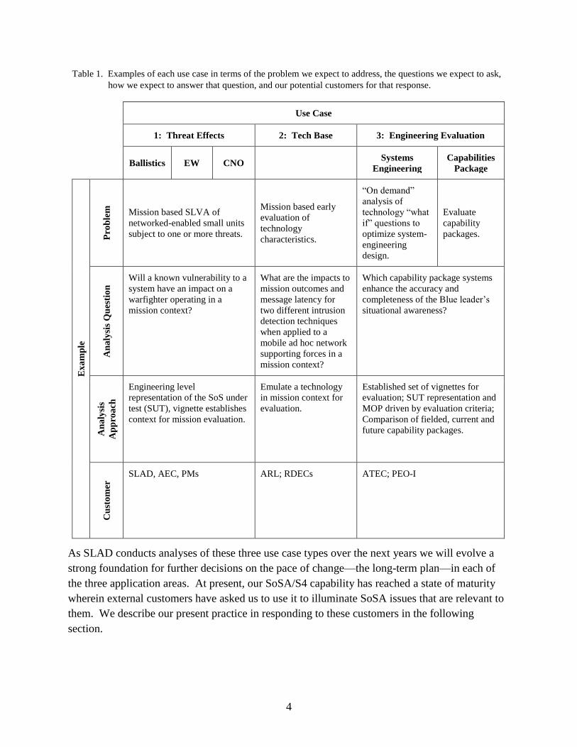
Table 1. Examples of each use case in terms of the problem we expect to address, the questions we expect to ask,
how we expect to answer that question, and our potential customers for that response.
Use Case
1: Threat Effects 2: Tech Base 3: Engineering Evaluation
Ballistics EW CNO
Systems
Engineering
Capabilities
Package
Ex
am
ple
Pro
ble
m
Mission based SLVA of
networked-enabled small units
subject to one or more threats.
Mission based early
evaluation of
technology
characteristics.
―On demand‖
analysis of
technology ―what
if‖ questions to
optimize system-
engineering
design.
Evaluate
capability
packages.
An
aly
sis
Qu
esti
on
Will a known vulnerability to a
system have an impact on a
warfighter operating in a
mission context?
What are the impacts to
mission outcomes and
message latency for
two different intrusion
detection techniques
when applied to a
mobile ad hoc network
supporting forces in a
mission context?
Which capability package systems
enhance the accuracy and
completeness of the Blue leader’s
situational awareness?
An
aly
sis
Ap
pro
ach
Engineering level
representation of the SoS under
test (SUT), vignette establishes
context for mission evaluation.
Emulate a technology
in mission context for
evaluation.
Established set of vignettes for
evaluation; SUT representation and
MOP driven by evaluation criteria;
Comparison of fielded, current and
future capability packages.
Cu
sto
mer
SLAD, AEC, PMs ARL; RDECs ATEC; PEO-I
As SLAD conducts analyses of these three use case types over the next years we will evolve a
strong foundation for further decisions on the pace of change—the long-term plan—in each of
the three application areas. At present, our SoSA/S4 capability has reached a state of maturity
wherein external customers have asked us to use it to illuminate SoSA issues that are relevant to
them. We describe our present practice in responding to these customers in the following
section.
5
3. Methodology
The principal aim of this paper is to clearly state SLAD’s current practice for conducting SoSA.
Although we hope that our treatment is sufficiently general to apply to any of the three use cases,
we realize that since engineering-level SoSA is a new discipline, it will surely continue to
evolve. Our present practice consists of five phases:
1. Define the Problem.
2. Develop the Model.
3. Build the Simulation.
4. Evaluate the Experiment.
5. Conduct the Study Assessment.
Before studying this methodology in detail, the reader less conversant with SLAD terms of art
such as ―survivability,‖ ―lethality,‖ ―vulnerability,‖ and ―susceptibility‖ should refer to the
appendix. The appendix also discusses some of the subtle distinctions between ―SoS,‖ ―SoSE,‖
and ―SoSA.‖ While our SoSA methodology may be of some interest to those whose primary
interest is in SoSE, the principal intended audience for this account of SLAD’s SoSA
methodology is those who will either conduct SoSA or use SoSA results.
3.1 Phase 1: Define the Problem
SoSA is a contact sport. The problem definition process is a collaborative effort between the
analytical team and the study sponsor or customer. As the team progresses through this phase, it
must develop a shared understanding of the customer’s specific problem. This understanding
facilitates decision-making that takes place in subsequent phases regarding resources, analysis
strategies, etc. This first phase establishes the foundation upon which the analytical team will
build the models, identify modeling gaps, determine resource requirements, analyze the data and
frame the results to answer a particular customer’s ―question‖. The quotation marks around
―question‖ highlight that an initial customer query may well require sharpening. We employ a
three-step approach to arrive at a clearly defined analytical question:
1. Elicit information from the customer to identify and crisply frame the key analysis issues
and objectives.
2. Identify the most important issues that must be illuminated for the analysis objectives to be
achieved.
3. Develop an experiment directive and obtain customer agreement to document the scope,
key objectives, and analysis issues for the study.

6
3.1.1 Identify the Objective(s)
Objectives should be specific, measurable, achievable, and realistic (5).
A specific objective is one that is accurate and free from ambiguity. For example, a proposed
objective to ―determine the impact of radio electronic warfare susceptibilities on a brigade
combat team (BCT)‖ is unacceptably ambiguous. However, the objective ―what is the impact of
susceptibilities in the Joint Tactical Radio System (JTRS) radio to intelligence warfighting
function as it supports a certain specific brigade operation?‖ is unambiguous and subject to
measurement.
A measurable objective is one that is supportable with simulation metrics. For the BCT example
above, the first proposed objective does not immediately suggest what quantities we should
measure, whereas the reformulated example more effectively suggests things to measure. For
example, if we adopted the time it took the intelligence officer to relay critical threat information
to the battalion commander as an effectiveness measure, then one could count the number of
simulated messages that were lost, or measure the simulated time between receipt by the
intelligence officer and delivery to the battalion commander.
An achievable objective is one that is answerable in the available time. In the example
discussed, if results must be delivered in six months, and the current application will only
support platoon operations, it is highly unlikely that the analyst will attain the BCT objective,
however stated, in the available time because necessary brigade-level models are unlikely to be
developed in six months.
A realistic objective is one that properly reflects current operational forces, needs, and
circumstances. In the BCT example, if either the radio is a poor representation of the JTRS or
the model of a brigade combat team is that of a Cold War era force, the analysis obtained will not
have the requisite degree of realism.
3.1.2 Identify the Issues
Once we identify the objectives, the next step is to develop specific study issues. To do this, the
team frames relevant analytical questions (5) to illuminate each objective. This process is not
purely deductive; individual analysts may well identify the issues differently. It is to reduce the
variance that we employ a multi-disciplinary team. Within the team, a military domain expert
will help properly portray the objectives in a tactical domain and to identify the relevant domain
concepts that will likely be present in the analysis. The technical domain expert in SLV analysis
will contribute expertise that facilitates constructing of issues relevant to a specific use case 1
SLV objective. The researcher will help to formulate the technology trades that are under study
for use case 2 projects. The system proponent or evaluator will help formulate the capability
package or system issues characteristic of use case 3. We frame all of these specific questions in
such a way that we can address them with appropriate measures and metrics.
7
Credible questions must be the right resolution match to the ―functional models‖ in the current
simulation environment†. The functional models within a given simulation are primary drivers
of the simulation results that will enable us to draw useful analytical conclusions. For example,
if our issue concerns the impact of a new class of intrusion detection methods for mobile-ad-hoc-
networks, our functional model for communications must be at a level of technical detail where
intrusion detection is relevant.
Not every phenomenon modeled will be germane to every SoSA issue and question. These
―context-setting models‖ must be present to provide an appropriate environment for functional
models, but their outputs are less critical to the overall analysis scheme. For example, the
platform mobility model provides the context for measuring network effects via platform
positions, yet its output is not crucial in the analysis.
Finally, there will likely be more than one issue per objective. From the major issues and
questions identified there will be several major themes that emerge as the focus for analysis.
Whatever the final tally of issues and analysis themes, the final step in identifying the issues is to
determine those that must be addressed for study success; these issues and the related questions
then become the essential elements of analysis (EEA) (5).
3.1.3 Experimental Directive
Once the analytical team has identified the objectives, issues, and the EEA, the final element of
the problem definition phase is to draft an experimental directive. The role of the directive is
threefold:
1. Provide a crisp, clear statement regarding the SoSA goal.
2. Succinctly capture each objective, issue, and EEA.
3. Provide an initial estimate of necessary resources and key study milestones.
The customer approves the directive. We seek and obtain this approval from an organizational
level commensurate to the resource commitments required.
† We do not intend to suggest that we limit the scope of questions that we can answer to what we have already modeled.
Credible questions exist independent of the means to answer them. If there are discrepancies between the resolution required to
answer a question, and the resolution of functional models available in the simulation, which implies that either software
development to create the functional models in sufficient detail is required or we must modify the question.
8
3.1.4 An Example Showing Phase 1 in Execution‡
The PM for the XYZ radio asks SLAD for an SLV assessment of its new radio. Initial
laboratory analysis reveals that the radio was susceptible to jamming energy when the jamming
energy exceeded the signal energy by 15 dB. With the initial laboratory analysis complete, and a
set of mitigations proposed, the PM asks SLAD to assess the SoS impact of not applying the
mitigations.
To address the PM’s question requires a lot of preliminary homework on system specification,
scheduling, capability, performance, and planned basis of issue. Suppose the homework reveals
that the Army plans to insert the XYZ radio into BCTs as a direct replacement for existing radio
systems. Since these radios are in use by all elements of the brigade, it is possible to undertake a
SoSA on an important warfighter function where the effects of jamming are readily observable.
The fires warfighting function emerged as most critical in discussions with the PM. SLAD
defined the SoSA problem as determining the impact of barrage jamming against the fires
warfighting function.
Ultimately, this agreement boiled down to the simple experimental directive: ―Assess the impact
of barrage jamming on the delivery of precision effects by field artillery against a predetermined,
moving target array.‖ Furthermore, the PM specifically wished to know the impact that jamming
had on various elements of the fires process, and that these elements formed the EEA.
3.2 Phase 2: Develop the Model
In phase 1, we defined the broad elements of a study; these steps included identifying the
objectives, developing the issues and the EEA, and creating and approving an experimental
directive. In phase 2, we transform these elements into a viable simulation study plan. The
study team will summarize the results from this phase via a study plan and a model definition;
however, if the study is sufficiently complex, the team may choose to develop separate analysis
and data management plans.
3.2.1 The Study Plan
The intent of the study plan (5–7) is to identify (1) a detailed mapping of issues to an EEA,
(2) the resources required in the study, and (3) a detailed project schedule with significant
milestones identified.
‡ We will use this example to illustrate our methodology as we describe each phase. The example derives from the threat
integration work of SLAD’s SoSA Integrated Process Team. Because our example focuses on EW, the relevant Integrated
Process Team (IPT) members are one of the authors (Smith) as the IPT Chair, Mr. Peter Bothner and Dr. Patrick Honan as EW
subject matter experts from SLAD. From New Mexico State University Physical Science Laboratory (NMSU\PSL), Mr. Joel
Eichelberger provided communications and software expertise, Mr. Jim Davidson constructed the tactical vignette that we
adapted, and Dr. Alex Pogel helped structure and conduct the analysis.
9
The study plan specifies the relationships between objectives, issues, and the EEA as identified
in the experimental directive. A multi-disciplinary analysis team should undertake developing
this specification. A military domain analyst will help identify the key military concepts that the
SoSA team must understand to illuminate a particular issue, while other technical specialists
contribute their understanding of the various underlying technologies and the doctrinal decision
processes that the simulated entities employing the technologies will use. Through the process
of understanding these cross-domain relationships for the vignette or scenario under
consideration, the team gains sufficient understanding to create one or more trial SoS models
with which to begin the analysis. By describing tactical missions within one or more warfighting
(8) functions in a particular mission context we are creating the model SoS that will be the
subject of study.
3.2.2 Create a Model
In addition to the study plan, another necessary analytical element is a model SoS. By model
SoS, we mean a representation of the SoS in a particular context that reflects valid doctrine, and
which is as simple as possible while containing the essential functional and context setting
models for the analysis.§
For example, suppose a customer needs to understand the changes in effectiveness of a brigade
combat team that is equipped with a technology to enhance situational understanding. The
intelligence warfighting function is clearly appropriate to consider in the analysis, and an EEA
might involve determination of how that technology influences the situational awareness of a
platoon within the brigade. We might ask the question: does better or timelier intelligence have
an observable effect on the outcome of a simulated combat?
Our model SoS will include at a minimum both Red and Blue forces; these forces will have a
command structure, be organized in some mutually supporting manner—for example, see the
monograph by Prosser (10)—and be equipped with an array of platforms and ancillary
equipment. In S4, we use the Vignette Editor Tool (VET) to arrange these forces and equipment
into the structure described in our model SoS. We can also use VET to select equipment from
the equipment database, place platforms on networks and assign various decision-making
processes to platforms and units to create our simulation of a SoS. These decision-making
processes determine the specific roles a particular agent representation will play in the
simulation, that is, battalion commander, company, commander, platoon leader, scout, etc.
§ The general issues of complexity and simplicity in models is beyond our scope here. However, the analyst often may be
tempted to create an overly complex model for the sake of ―domain realism‖. However, as the quote by Phillip Anderson in his
1977 Nobel Prize winning speech, as cited in the work by Mitchell on page 224 (9), indicates a parsimonious model often
provides better insight into the questions at hand: ―The art of model-building is the exclusion of real but irrelevant parts of the
problem, and entails hazards for the builder and the reader. The builder may leave out something genuinely relevant; the reader,
armed with too sophisticated an experimental probe or too accurate a computation, may take literally a schematized model whose
main aim is to be a demonstration of possibility.‖
10
The analytical team’s goal in building a model SoS to study is to create a ―reasonable‖ space of
tactical and technological possibilities from which will result simulation outcomes to address the
issues and EEA. These outcomes are much more complex than identifying whether Blue
accomplished its mission (―won‖) or the simulated force exchange ratio. For the engineering
characterization of the equipment to add real value to the intellectual process there are dozens
and sometimes hundreds of potentially useful variables tracked throughout the simulation run. In
addition to variables that track traditional metrics such as losses, we can also track many unique
classes of variables to aid our analyses. For example, we track such time-series measurements as
the situational awareness of the commanders in a given experiment. In respect to the decision-
making, we analyze the accuracy of the decisions over time using a version of ground truth that
is computed (11, 12) via the use of assessor agents. The ability to assess both situational
awareness and the accuracy of decisions over time for each element of the simulation is just one
example of SLAD’s ability to assess the effects CNO and EW have upon the EEA. The art of
SoSA is determination of which variables and interactions best illuminate the EEA of interest.
As will be obvious from the previous discussion, developing an appropriate analysis vignette is a
complex task unique to each analysis. However, for each analysis we conduct, we will use as
one or more vignettes approved by the appropriate U.S. Army Training and Doctrine Command
(TRADOC) user.
3.2.3 Develop an Analysis Plan
Another component of the study plan is the analysis plan. It documents the broad analytical
themes that the study team will explore during the course of the assessment. The analytical team
develops these themes as they work to understand the relationships between the study issues and
EEA, and the modeled military missions that will provide the simulation results for assessment.
As the study team relates the issues and EEA to more fundamental simulation outputs, they will
generate specific Measures of Merit (5) that in turn will be calculated from the metrics generated
during the course of a simulation run. In so doing, the team is laying a sufficiently detailed
foundation for the resulting assessment so that the study sponsor can ascertain that the analysis
can satisfactorily address their issues and needs. A secondary goal in this activity is to ensure
that the SoS model and resulting simulation will produce the simulation results of the kind
needed to produce the assessment.
The team may choose not to document the plan as a separate deliverable. However, if the
analysis is complex, or there are a multiple issues and EEA in the study, it is probably wise to
document the analysis plan independent of the study plan. This documentation should serve as
part of the basis for the final report.
3.2.4 A Continued Example to Show Phase 2 in Execution
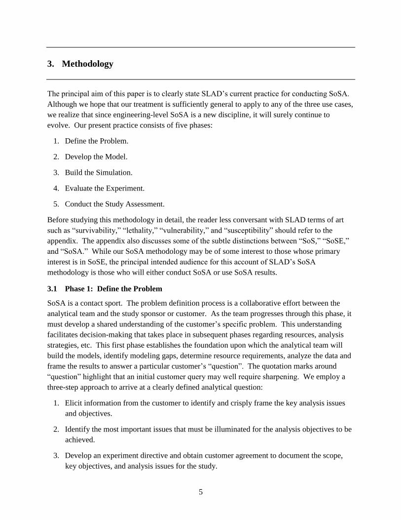
Continuing the example we began in phase 1, the study team turned to Army doctrine and
developed a simple model of the fires warfighting function commensurate with the question.
11
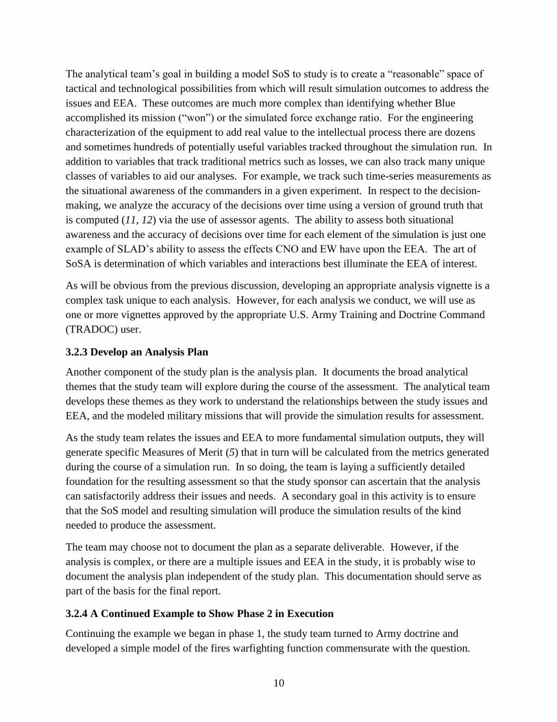
Figure 1 presents this simple model with some of the major coordinating functions that the
process must execute in order to conduct a single fire mission.
Figure 1. Simplified model of the fires warfighting function depicting significant steps that must occur for the
process to complete successfully.
From figure 1, we observe four items that the PM considered EEA, the actions of the forward
observer, the fire direction center, the section chief, and the cannon controllers. For MOP, the
analysis team decided upon measuring both the time to, and the success of, issuing a:
• Call for fire to Fire Direction Center
• Fire request to Section Chief
• Designate order to Forward Observer
• Fire order to Cannon Controller
Each corresponding element of this process must issue their orders successfully for the fires
mission given to that warfighting process to achieve its intended effect. Note this intended effect
is independent of any particular vignette or mission depiction.
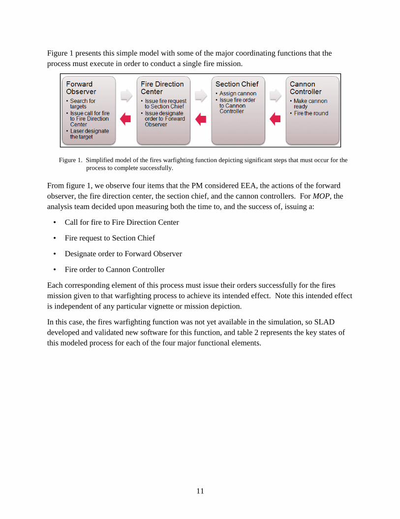
In this case, the fires warfighting function was not yet available in the simulation, so SLAD
developed and validated new software for this function, and table 2 represents the key states of
this modeled process for each of the four major functional elements.
12
Table 2. Key software states in a model representation of a fires warfighting function process.
Forward Observer Fire Direction Center
Section Chief Paladin Battery
Search for targets
Issue call for fire to FDC
Wait until FDC ready
Wait until enemy enters target
area
Issue fire request message to FDC
Wait for designate order
from FDC
Laser designate the target
Issue further fire requests to FDC
as necessary
Receive call for fire from FO
Issue fire request to Section Chief
Wait until Section Chief
ready
Issue fire order to Section Chief
Wait for shot report
Issue designate order to FO
Process additional calls for fire from FO
as necessary
Receive tube assignment from
Section Chief
Make tube ready for shot
Inform Section Chief tube is
ready
Wait for fire order from
Section Chief
Fire the roundInform Section
Chief shot is fired
Process additional tube assignments as
necessary
13
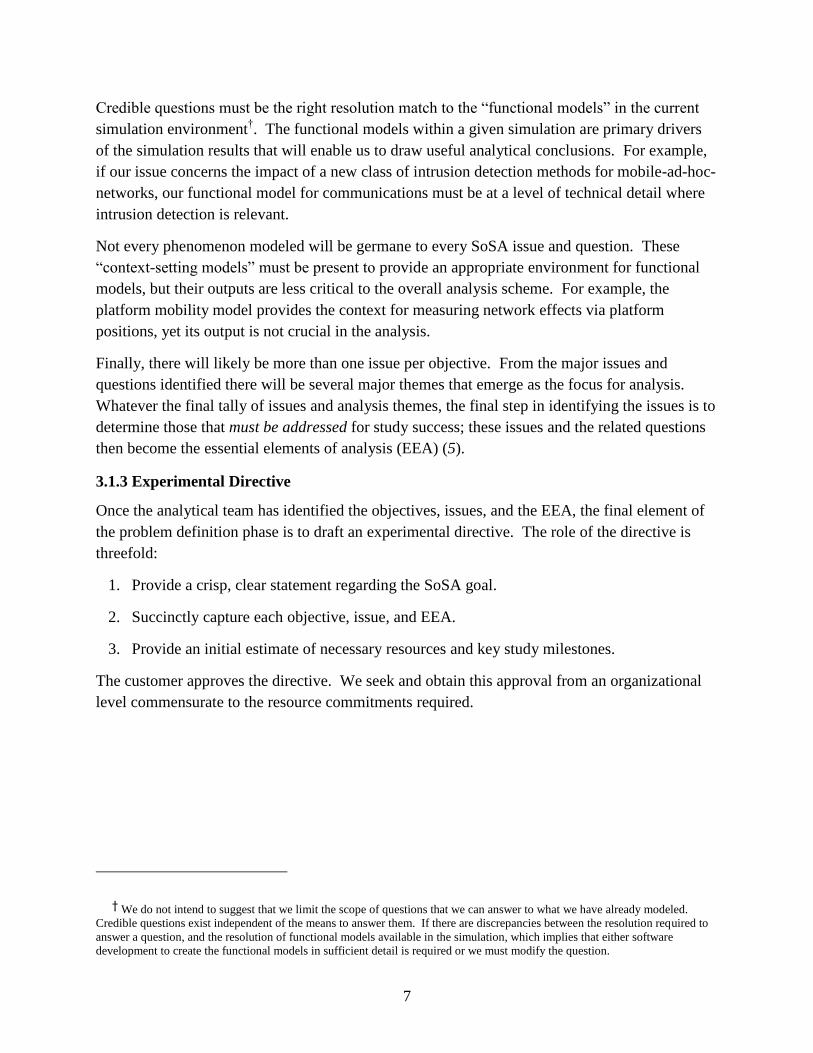
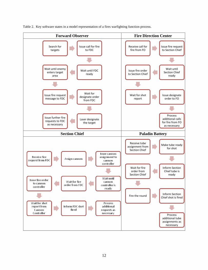
The final element of phase 2 is to define a context within which to gather data to address the
question posed, and the essential elements of analysis. Here, we chose a simple vignette. Blue is
to identify Red targets moving north and use precision fires to prevent Red from moving a
combat effective unit north of Phase Line (PL) Gold (see figure 2). The presence of a combat
effective platoon (three or more T-72s with capabilities to fire either their main cannon or Anti-
Tank Guided Missiles [ATGMs]) north of PL Gold became the measure of effectiveness (MOE)
for the Blue fires warfighting function. In EW runs, a Red jammer will move along the southern
road and jam for a five-minute interval after Blue designates a target.
Figure 2. A notional experimental vignette in which a Red tank platoon seeks to move north and impede the
transit of Blue forces through the northern mobility corridor.
3.3 Phase 3: Build the Simulation
Through phases 1 and 2 we created a model SoS for our analysis, defined a study framework,
and determined the required resources to conduct our study. The next task is to translate the
model SoS into a simulation that a computer can execute. The S4 (3) environment includes tools
designed so that a user can translate a model SoS into simulation code that is machine
executable.
From the study directive, the analytical team will create an execution matrix for the simulation
experiment. The execution matrix identifies the specific sets of initial conditions that will be run
for the study. It is difficult to enumerate a set of initial runs that covers the most promising
waterfront without allowing a combinatorial explosion that can prevent the study team from
meeting agreed deadlines. The study team should consult with the sponsor to assure that the
study will cover the sensitivity analyses of most interest to that party. The team must also draw
on its experience with previous studies, and attempt to anticipate which parameters are most apt
to drive study results. Specification of the initial matrix is inherently partly judgmental,
involving practical tradeoffs as well as intellectual considerations.
14
For a given simulation experiment, a priori prediction of which SoS runs will turn out to be the
most interesting or illuminating is notoriously difficult. In many cases, study of the results from
the original matrix shows that additional runs should be made for completeness, or to more fully
articulate a trend.
3.3.1 A Continued Example to Show Phase 3 in Execution
At this point, all the preparatory work necessary to conduct the experiment is complete. The
SoSA team converted the mission context provided in figure 2 to a representation that will
execute on a computer. They also instrumented the simulation to audit particular variables
relevant to the measures of performance and the MOE that correspond to the EEA. Finally, they
established a run matrix that contained both runs with jamming and runs without. They gathered
appropriate simulation results and prepared the data for analysis in the next phase.
3.4 Phase 4: Evaluate the Experiment
After the team completes the planned simulation runs, it will have appropriate simulation output
to serve as the basis for the analysis. In practice, these files will often be several gigabytes and
contain hundreds of metrics, each sampled over thousands of time steps for each Monte Carlo
run. The team refines its analysis of the simulated situation in a two-phase process: preliminary
data exploration and conclusion formation. We describe the data exploration process here and
the conclusion formation process in the next section as Phase 5.
The team usually will go through several steps including:
1. Search for outliers and determine whether they are mistakes or key data points.
2. Familiarize themselves with output trends and anomalies.
3. Categorize the results.
4. Observe and analyze within categories.
5. Identify the emerging trends drawn over all categories.
The team’s goal in this phase is to identify the most significant emerging results relative to the
study issues and the EEA. Since there is often a time lag between the formation of the study plan
and the delivery of simulation output, these preliminary analytical steps allow the team to re-
assess—in terms of actual simulation results—where the analysis is going relative to the
sponsor’s needs.
Familiarization is a time-consuming process: the analysts endeavor to understand the results
presented by the simulation. They search for the presence of significant similarities and
differences. They will use standard statistical techniques to see what sort of distribution the
output metrics exhibit over the run space. They will also determine whether patterns of mission
accomplishment (or non-accomplishment) exist. A related aspect of this activity is to identify
15
significant clusters of similar results that seem odd or counterintuitive; these clusters may give us
high payoff information that illuminates the various EEA. To assist in this work, team members
may use one of the data visualization tools included in the S4 tool set and developed expressly
for visualizing quantitative data in the context of a military mission called QuickLook (13).
QuickLook is software that was inspired by Minard’s famous depiction of Napoleons march to
Moscow and subsequent return. Tufte (14) cites Minard’s effort as perhaps the best graphic ever
drawn.
When the team is satisfied that they have valid results to analyze, their next step is to identify
key characteristics and patterns in the output that will allow them to categorize the runs and
results. Good judgment is required here. For example, one characteristic may be that when
reaching a key piece of terrain, a unit moves to the left or the right. Either choice may be valid
according to doctrine; yet, each choice results in a different pool of data. By placing the
simulation output into contextually relevant categories that are also operationally relevant, the
multi-disciplinary team guarantees that subsequent analyses rest on a tactically sound footing,
grounded in the domain and relevant to the warfighter. This is a more appropriate method for
getting to the key information for SLV analysis than statistically slicing and dicing a less
differentiated data set.
Within the categorized results, the analysts’ task is to discover relationships that may hold value
for assessing the mission contributions of the technologies under study. Ultimately, this work
establishes the foundation for the phase 5 analysis to follow. Another purpose for the early
analysis step is to identify emerging results and present these results to the study sponsor. The
goal here is to (1) ascertain the continuing relevance of the study issues, and (2) alert the study
sponsor to any particularly significant emerging results.
For example, in an analysis of an active protection system for ground vehicles, the analysis
considered three distinct Blue courses of action (COA). Each COA represented a valid doctrinal
approach to the same mission. For each COA, the analysis team computed the mean lifetime of
the Blue platforms as a MOE. They were statistically different when they were rank-ordered by
the MOE. However, when the team included explicit focus on vehicles equipped with the active
protection system in the analysis, they discovered that runs with the platforms so-equipped
yielded results in the upper quartile of mean lifetime. This result held independently of COA.
Thus, what initially appeared to be statistically disparate pools of simulation outputs yielded a
conclusion that was more general than the disparate pools would have suggested. This
observation is relevant to the PM developing or considering active protection technology in that
it suggests a wider applicability for their product.
16
The analysis team cannot apply an algorithm as it mines simulation results. Ultimately, the goal
of this phase is to identify the most interesting, important, or surprising relationships in the
results, and to determine the significance of metrics that are appropriate to these regimes. The
process results in a tentative set of analysis conclusions grounded in military mission
accomplishment.
3.4.1 A Continued Example to Show Phase 4 in Execution
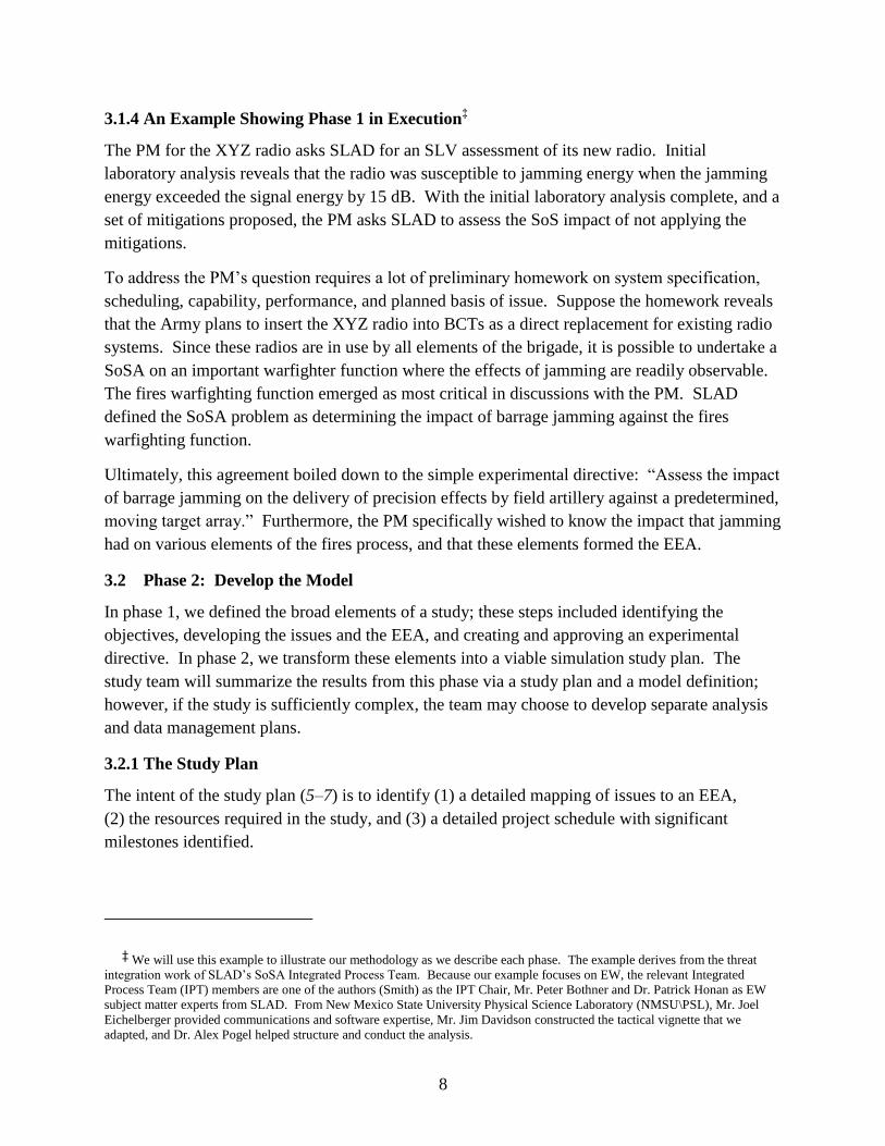
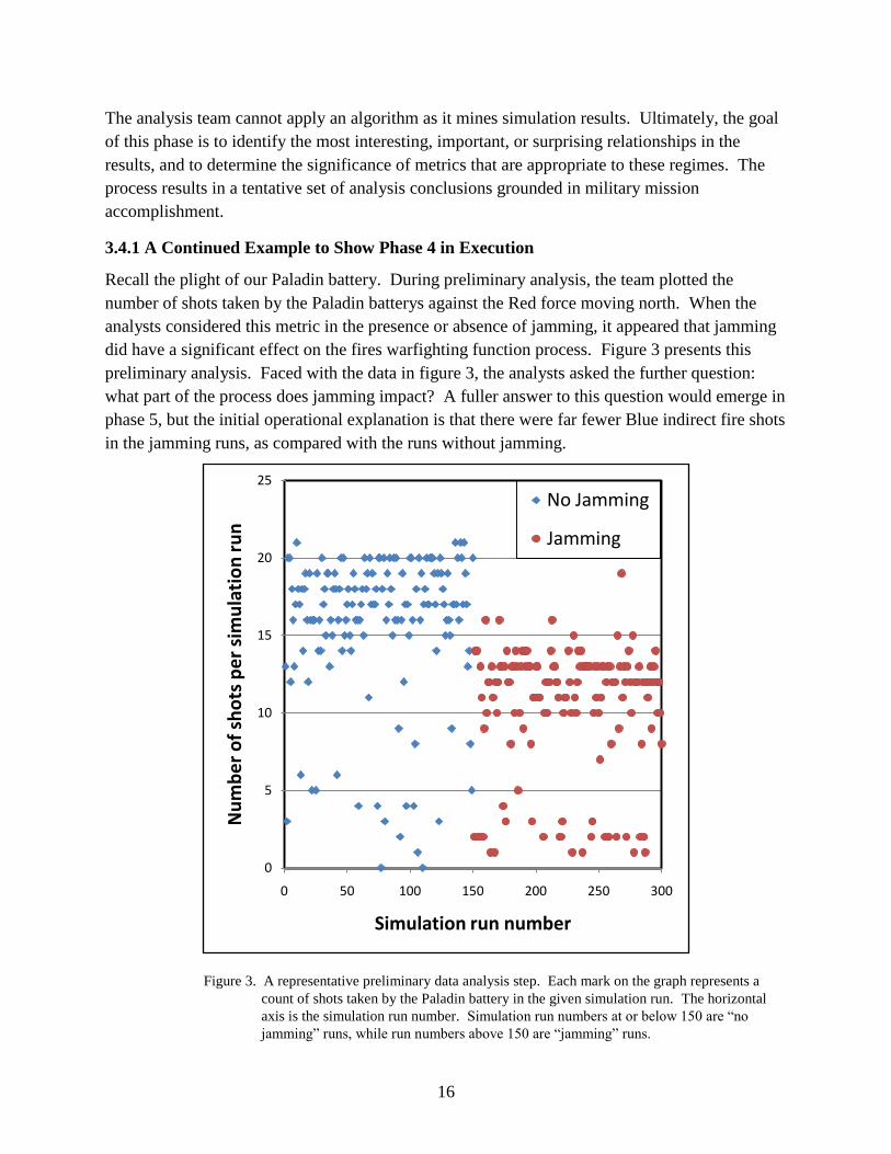
Recall the plight of our Paladin battery. During preliminary analysis, the team plotted the
number of shots taken by the Paladin batterys against the Red force moving north. When the
analysts considered this metric in the presence or absence of jamming, it appeared that jamming
did have a significant effect on the fires warfighting function process. Figure 3 presents this
preliminary analysis. Faced with the data in figure 3, the analysts asked the further question:
what part of the process does jamming impact? A fuller answer to this question would emerge in
phase 5, but the initial operational explanation is that there were far fewer Blue indirect fire shots
in the jamming runs, as compared with the runs without jamming.
Figure 3. A representative preliminary data analysis step. Each mark on the graph represents a
count of shots taken by the Paladin battery in the given simulation run. The horizontal
axis is the simulation run number. Simulation run numbers at or below 150 are ―no
jamming‖ runs, while run numbers above 150 are ―jamming‖ runs.
0
5
10
15
20
25
0 50 100 150 200 250 300
Nu
mb
er
of
sho
ts p
er
sim
ula
tio
n r
un
Simulation run number
No Jamming
Jamming
17
3.5 Phase 5: Conduct the Study Assessment
In this final phase, we describe specific conclusions and perhaps recommendations that relate to
the EEA developed in phase 2. Recommendations might be for substantial actions or decisions
by the study sponsor or they might identify matters requiring further study. At this point in the
assessment process, the analysis team will have developed considerable insight into the
simulation output and will have drawn tentative conclusions. The team may have presented
these insights and tentative conclusions to the study sponsor, and made subsequent revisions or
responded to further requests. What remains is for the team to state and carefully vet their
conclusions in the context of the study goals and the EEA, and form them into a coherent
presentation.
The use case 1 problem of conducting SLV assessments in a SoS context means identifying the
impact on mission success caused by individual item-level susceptibilities. One can think of the
analysis as aggregating many observations as the modeled leaders direct various threats against
specific susceptibilities. Each run of our simulation model may result in tens or hundreds of
these attempts, generated from a broad distribution of initial conditions. The analytical team
must seek to identify trends and anomalies that arise from many runs of a complex simulated
scenario.**
Some anomalies may result from coding or input errors; others may be essentially
illuminating for the questions under study.
In practice, the analytical team will condition their approach on both the type of use case and the
specific issues and the EEA for the study. It is likely that individual SoSA analysts will
approach a given problem differently. It is here that the strength of a multi-disciplinary team
comes in to play; the give and take of team dynamics often reveals insights and conclusions that
are substantially different and deeper than individual analysts would have been able to reach on
their own. This process helps drive the analysis to well-founded conclusions that are rooted in
the military domain, relevant to the warfighter, and grounded on solid engineering data.
** One such tool that facilitates this process by allowing the data to drive the formation of concepts, and exploration of the
space of concepts, is called Formal Concepts Analysis (FCA) (15). It is beyond the scope of this report to discuss FCA except to
say that it is a concept formation and exploration method that identifies co-occurrences of sets of attributes of individual
observations, called intents, and sets of individual observations, called extents. The computation of these concepts through
intent-extent pairs has a well-developed mathematical foundation (mathematical lattice theory [16]), and this decomposition of
the notion of concept is based upon centuries of philosophical developments (17) and established in the international standard
ISO 704. The use of FCA, as it applies to SoSA and S4, centers around two software packages. One package is called Seqer
(18), a tool that allows an analyst to observe and graphically explore assertions based on intent-extent pairs formed over the space
of simulation data, and RAGE (19), a tool that allows an analyst to form assertions based on intent-extent pairs formed over the
space of simulation data. Seqer provides a complex, but convenient way to visualize the simulation output data in a manner that
allows an analyst to discover relationships that may otherwise hide in a mass of numerical simulation data. As discussed in phase
4, the analyst may make observations within specific categories of simulation data. The analyst expectation is that these
observations may hold over many such categories; however, the observations may hold with varying strengths. These initial
observations become the intent, and the extent is the hypothesis the analysts wishes to test. In this case, RAGE allows the analyst
to draw these conclusions from the data along with confidence intervals, odds ratios, and other similar statistical measures.
18
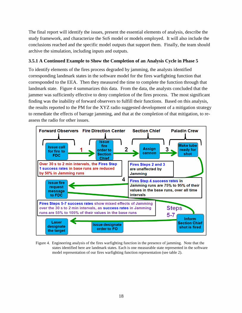
The final report will identify the issues, present the essential elements of analysis, describe the
study framework, and characterize the SoS model or models employed. It will also include the
conclusions reached and the specific model outputs that support them. Finally, the team should
archive the simulation, including inputs and outputs.
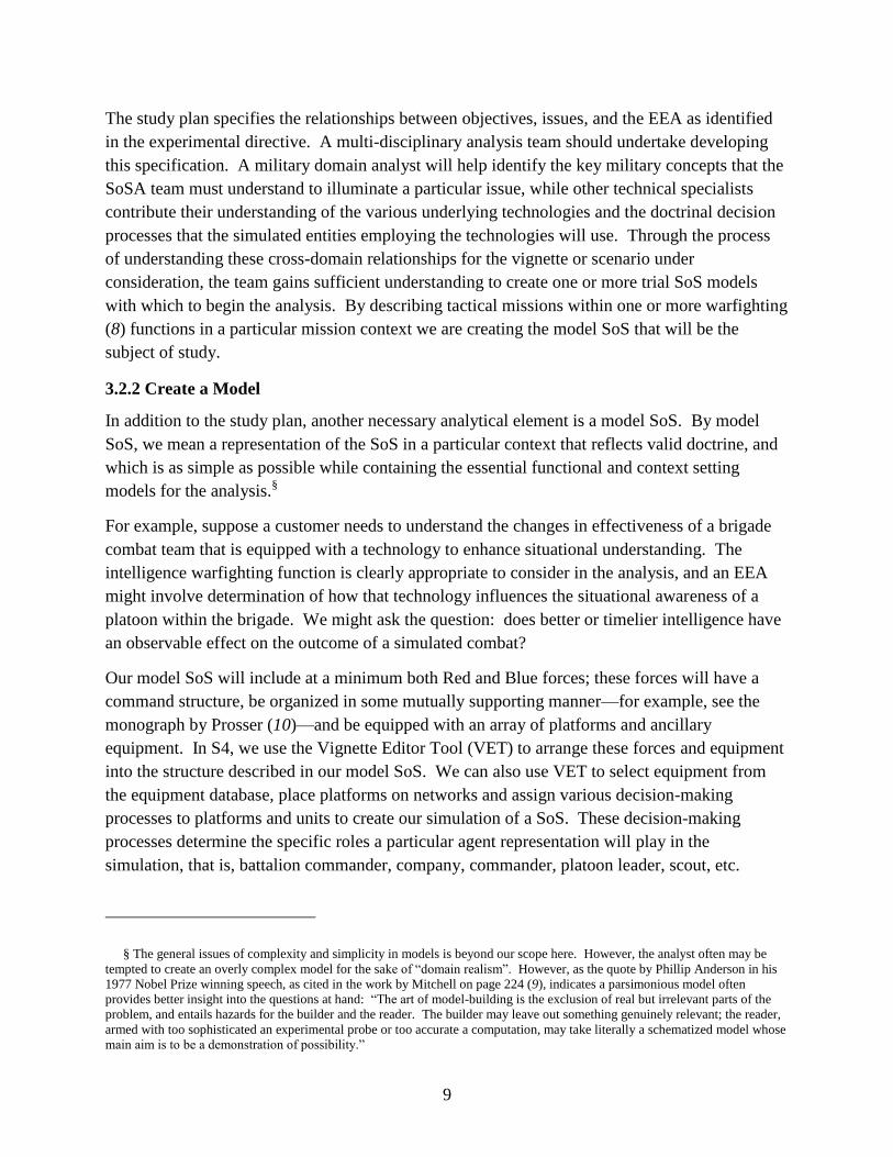
3.5.1 A Continued Example to Show the Completion of an Analysis Cycle in Phase 5
To identify elements of the fires process degraded by jamming, the analysts identified
corresponding landmark states in the software model for the fires warfighting function that
corresponded to the EEA. Then they measured the time to complete the function through that
landmark state. Figure 4 summarizes this data. From the data, the analysts concluded that the
jammer was sufficiently effective to deny completion of the fires process. The most significant
finding was the inability of forward observers to fulfill their functions. Based on this analysis,
the results reported to the PM for the XYZ radio suggested development of a mitigation strategy
to remediate the effects of barrage jamming, and that at the completion of that mitigation, to re-
assess the radio for other issues.
Figure 4. Engineering analysis of the fires warfighting function in the presence of jamming. Note that the
states identified here are landmark states. Each is one measurable state represented in the software
model representation of our fires warfighting function representation (see table 2).
19
4. Summary
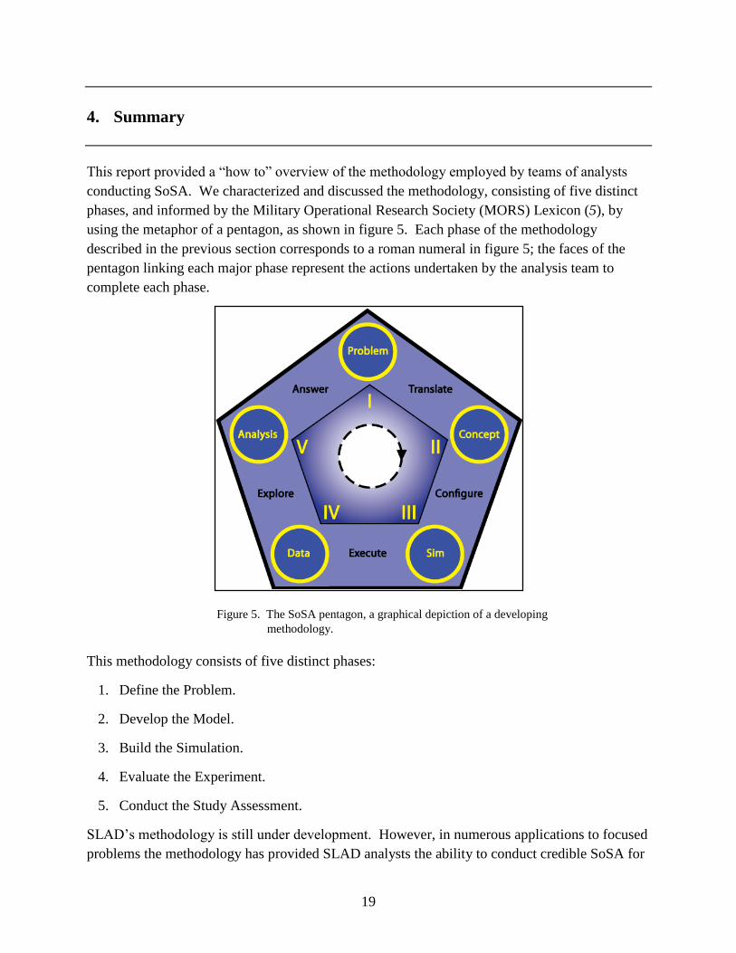
This report provided a ―how to‖ overview of the methodology employed by teams of analysts
conducting SoSA. We characterized and discussed the methodology, consisting of five distinct
phases, and informed by the Military Operational Research Society (MORS) Lexicon (5), by
using the metaphor of a pentagon, as shown in figure 5. Each phase of the methodology
described in the previous section corresponds to a roman numeral in figure 5; the faces of the
pentagon linking each major phase represent the actions undertaken by the analysis team to
complete each phase.
Figure 5. The SoSA pentagon, a graphical depiction of a developing
methodology.
This methodology consists of five distinct phases:
1. Define the Problem.
2. Develop the Model.
3. Build the Simulation.
4. Evaluate the Experiment.
5. Conduct the Study Assessment.
SLAD’s methodology is still under development. However, in numerous applications to focused
problems the methodology has provided SLAD analysts the ability to conduct credible SoSA for

20
small forces (battalion or less) in an operationally representative environment. Applications of
this methodology to problems of ballistics analysis in a SoS context were presented to the
National Defense Industry Association and the Live, Virtual and Constructive Simulation
conferences (20, 21). We also gave a more general overview to the Army Operations Research
community (22) and to the National Defense Industry Association conference (23).

21
5. References
1. U.S. Army Force Operating Capabilities; TRADOC Pamphlet 525-66; Headquarters,
Training and Doctrine Command: Ft. Monroe, VA, Mar. 7, 2008.
2. Starks, M. W.; Flores, R. New Foundations for Survivability/Lethality/Vulnerability
Analysis (SLVA); Technical Note ARL-TN-216; U.S. Army Research Laboratory: White
Sands Missile Range, NM, Jun, 2004.
3. Bernstein, R., Jr.; Flores, R.; Starks, M. W. Objectives and Capabilities of the System of
Systems Survivability Simulation (S4); Final Report ARL-TN-260; U.S. Army Research
Laboratory: White Sands Missile Range, NM, Jul, 2006.
4. U.S. Army Army Force Generation; Army Regulation 525-29; Headquarters, Department
of the Army: Mar. 14, 2011.
5. Military Operational Research Society. MORS experimentation lexicon. 2008. URL:
http://morsnet.pbwiki.com/Experimentation (accessed January 30, 2009).
6. Kleijnen, J.P.C.; Sanchez, S. M.; Lucas, T. W.; Cioppa, T. M. A User’s Guide to the
Brave New World of Designing Simulation Experiments. INFORMS J. Comput. 2005, 17
(3), 263–289.
7. Law, A. M.; Kelton, W. D. Simulation Modeling and Analysis; 3rd ed.; McGraw-Hill:
Boston, 2000.
8. U.S. Army Operations; Field Manual 3-0; Headquarters, Department of the Army:
Washington, DC, Feb. 27, 2008.
9. Mitchell, M. Complexity: A Guided Tour; Oxford University Press: Oxford England,
2009.
10. Prosser, B. D. Nested Concepts: Implementing Commander's Vision and Securing Unity
of Effort; Monograph U.S. Army Command and General Staff College, School of
Advanced Military Studies: Ft. Leavenworth, KS, May. 22, 1997.
11. Davidson, J.; Pogel, A.; Smith, J. A. The Role of Battle Command in Information
System Assessments. In the Proceedings of the 13th Annual International Conference on
Industrial Engineering Theory, Applications and Practice; International Journal of
Industrial Engineering: 2008; pp. 154–160.
12. Davidson, J.; Pogel, A.; Smith, J. A. Assessments of IT's Support of C2. In the
Proceedings of the 14th International Command and Control Research and Technology
Symposium (ICCRTS 2009); 2009.
22
13. QuickLook: A Data Visualization Tool, developed by New Mexico State University,
Developed under Contract No: DATM05-01-C-0026 to the Army Research Laboratory:
2010.
14. Tufte, E. R. The Visual Display of Quantitative Information; 2nd ed.; Graphics Press:
Cheshire, CT, 2001.
15. Ganter, B.; Wille, R. Formal Concept Analysis: Mathematical Foundations; Springer:
New York, 1999.
16. Birkhoff, G. Lattice Theory; 3d ed.; American Mathematical Society: Providence, 1967.
17. Arnauld, A.; Nicole, P. La Logique Ou L'Art De Penser, Contenant, Outre Les Règles
Communes, Plusieurs Observations Nouvelles Propres à Former Le Jugement; Chez
Charles Savreux: Paris, 1662.
18. Seqer: A Formal Concept Analysis Software Package, developed by New Mexico State
University under Contract No: DATM05-01-C-0026 to the Army Research Laboratory:
2010.
19. RAGE: Rule Assembler, Generator, and Evaluator Software Package, developed by
New Mexico State University, Developed under Contract No: DATM05-01-C-0026 to
the Army Research Laboratory: 2010.
20. Smith, J. A.; Ward, B. S. System of Systems - Survivability, Lethality, Vulnerability
Assessment: Ballistic Vulnerability Modeling Demonstration. In the Proceedings of the
25th Annual National Test and Evaluation National Conference; National Defense
Industry Association: 2009.
21. Smith, J. A.; Ward, B. S. System of Systems - Survivability, Lethality, Vulnerability
Assessment: Ballistic Vulnerability Modeling Demonstration. In the Proceedings of the
14'th Annual Live-Virtual-Constructive Conference; 2009.
22. Smith, J. A.; Bother, P.; Castañares, A.; Young, R. J. A Method to Assess Survivability,
Lethality and Vulnerability in a System of Systems. In the Proceedings of the 48th
U.S.Army Operations Research Symposium (AORS 2009); 2009.
23. Smith, J. A. A Method to Assess Survivability, Lethality and Vulnerability in a System
of Systems. In the Proceedings of the 26th Annual National Test and Evaluation
National Conference; National Defense Industry Association: 2010.
24. Jamshidi, M. System of Systems Engineering: Innovations for the 21st Century; Wiley:
New York, 2008.
25. Jamshidi, M. System of Systems Engineering: Principles and Applications; CRC: 2008.
26. Army Research Laboratory Workshop on System of Systems Analysis. Sponsored by the
Army Research Office; Las Cruces, NM, March 17, 2009.
23
27. Deitz, P. H.; Reed, H. L., Jr.; Klopcic, J. T.; Walbert, J. N. Fundamentals of Ground
Combat System Ballistic Vulnerability/Lethality; 2009.
28. DeLaurentis, D. A.; Callaway, R. K. A System-of-Systems Perspective for Public Policy
Decisions. Review of Policy Research 2004, 21 (6), 829–837.
29. U.S. Department of Defense System of Systems Systems Engineering Guide:
Considerations for Systems Engineering in a System of Systems Environment; December
22, 2006.

24
INTENTIONALLY LEFT BLANK.
25
Appendix. Definitions and SoS, SoSE, and SoSA Discussion
A-1. Definitions
The term system of systems (SoS) is the subject of much recent discussion; see for example
chapter one of works by Jamshidi (24, 25) and an ARL workshop in 2009 (26). While a
consensus meaning has not yet evolved, in this paper we will use the definition for SoS
developed within SLAD as part of a broader ARL effort:
A SoS ―is a collection of interlinked and mutually dependent systems that has properties and
capabilities well beyond the simple union of the independent attributes of its constituent
systems.‖
This paper frequently uses the words survivability, vulnerability, lethality, and susceptibility
(SLV) and their cognates. We follow the definitions provided by the work of Deitz et al. (27):
Survivability: The total capability of a system (resulting from the synergism among
personnel, materiel, design, tactics, and doctrine) to avoid, withstand, or recover from
damage to a system or crew in hostile (man-made or natural) environments without
suffering an abortive impairment of its ability to accomplish its designated mission.
Vulnerability: The characteristics of a system that cause it to suffer degradation (loss or
reduction of capability to perform the designated mission) as a result of having been
subjected to a hostile environment on the battlefield.
Lethality: The ability of a weapon system to cause the loss of, or degradation in, the
ability of a target system to complete its designated mission.
Susceptibilities: The characteristics of a system that make it unable to avoid being
engaged by threats on the battlefield.
The phrase system of systems is contained in some related phrases such as system of systems
engineering and system of systems analysis
A-2. SoS Engineering and SoS Analysis
SoS engineering (SoSE) (24, 25) typically focuses on the process of engineering development for
both constituent technologies and their connections within the SoS. For example, engineers are
currently designing the next generation automated traffic systems (28). The designers of such
systems typically abstract the human part of the SoS via simple rules that are valid over a wide
range of likely situations. A very similar process occurs in the engineering of many military SoS
(26, 29). For these systems, the emphasis remains largely on ―packages‖ of constituent
technologies, with human factors aspects captured in a few standardized scenarios. The material
26
developers define (or receive) requirements for the constituent technologies over a range of
military domain contexts. They recognize that in actual military operations the soldiers that
employ a SoS may well face scenarios that vary considerably from the standard scenarios used in
design, and that in the novel scenarios there may be less than optimal performance.
For military SoS analysis (SoSA), the adaptation of using Soldiers in their doctrinal roles within
a specific scenario as they employ the SoS technology is of essential interest (2). Not only can
alternative arrangements of the constituent technologies yield different analytical results,
different simulated adaptations can too. Therefore, a credible analysis must consider the
technology, the requisite mechanisms for human adaptation to both the technology and the local
circumstances, and the scenario itself as key elements of the analysis. Consequently there is a
more inclusive focus here than in system engineering.
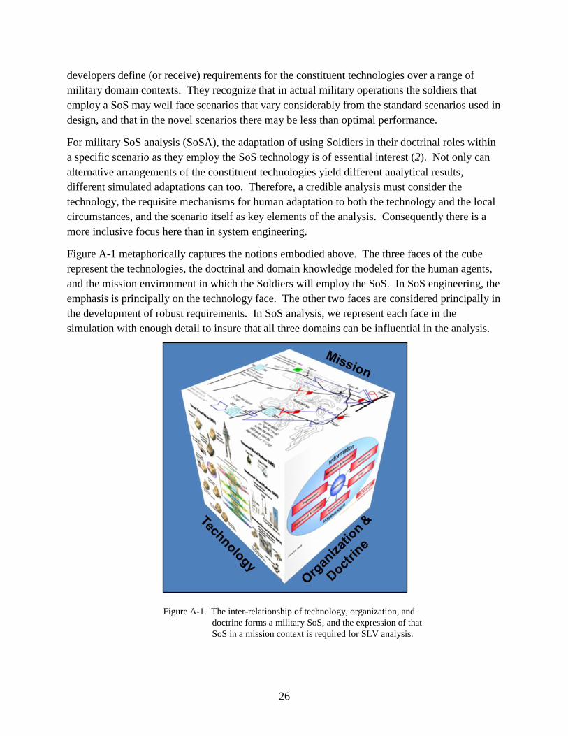
Figure A-1 metaphorically captures the notions embodied above. The three faces of the cube
represent the technologies, the doctrinal and domain knowledge modeled for the human agents,
and the mission environment in which the Soldiers will employ the SoS. In SoS engineering, the
emphasis is principally on the technology face. The other two faces are considered principally in
the development of robust requirements. In SoS analysis, we represent each face in the
simulation with enough detail to insure that all three domains can be influential in the analysis.
Figure A-1. The inter-relationship of technology, organization, and
doctrine forms a military SoS, and the expression of that
SoS in a mission context is required for SLV analysis.
27
List of Symbols, Abbreviations, and Acronyms
ARFORGEN Army Force Generation
ARL U.S. Army Research Laboratory
ATEC Army Test and Evaluation Command
ATGM Anti-Tank Guided Missiles
BCT brigade combat team
CNO computer network operations
COA course(s) of action
EEA essential elements of analysis
EW electronic warfare
FCA Formal Concepts Analysis
IPT Integrated Process Team
JTRS Joint Tactical Radio System
MOE measure(s) of effectiveness
MOP measure(s) of performance
MORS Military Operational Research Society
NMSU/PSL New Mexico State University Physical Science Laboratory
PEO Program Executive Office
PL Phase Line
PM program manager
S4 System of Systems Survivability Simulation
SLAD Survivability/Lethality and Analysis Directorate
SLV survivability, lethality, and vulnerability
SLVA survivability, lethality, and vulnerability analyses
SoS system of systems

28
SoSA system of systems analysis
SoSE system of systems engineering
SUT system under test
TRADOC U.S. Army Training and Doctrine Command
VET Vignette Editor Tool
No. of No. of
Copies Organization Copies Organization
29
1 (PDF) ADMNSTR
DEFNS TECHL INFO CTR
DTIC OCP
8725 JOHN J KINGMAN RD
STE 0944
FT BELVOIR VA 22060-6218
3 HCs US ARMY RSRCH LAB
ATTN RDRL CIO MT
TECHL PUB
ATTN RDRL CIO LL
TECHL LIB
ATTN IMNE ALC HRR
MAIL & RECORDS MGMT
2800 POWDER MILL ROAD
ADELPHI MD 20783-1197
1 CD US ARMY RSRCH LAB
1 WORD MELE ASSOCIATES INC
VERSION ATTN RDRL SLE E
D NEVAREZ
BLDG 1624 ROOM 225
WSMR NM 88002-5501
3 CDs US ARMY RSRCH LAB
ATT RDRL SLE
J A SMITH
WSMR NM 88002-5513
2 CDs US ARMY RSRCH LAB
ATT RDRL SLE
E ZARRET
R FLORES
WSMR NM 88002-5513
5 CDs US ARMY RSRCH LAB
ATT RDRL SLE G
J THOMPSON
L ANDERSON
K AUSTIN
I LUJAN
R VELASQUEZ
WSMR NM 88002-5513
2 CDs US ARMY RSRCH LAB
ATT RDRL SLE I
A CASTANARES
J MEDRANO
WSMR NM 88002-5513
3 CDs NEW MEXICO STATE UNIVERSITY
PHYSICAL SCIENCES
LABORATORY
ATTN RAY BERNSTEIN JR
MSC PSL/PO BOX 30002
LAS CRUCES NM 88003-8001
2 CDs USRL
RDRL SLE W
P BOTHNER
P HONAN
FT MONMOUTH NJ
1 CD DOT&E
ATTN J STREILEIN
1700 DEFENSE PENTAGON
WASHINGTON DC 20301-1700
1 CD SAAL ZE
ATTN T EDWARDS
105 ARMY PENTAGON
WASHINGTON DC 20310-0103
ABERDEEN PROVING GROUND
1 CD US ARMY DEV TEST COM
TEDT TMT
314 LONGS CORNER RD
APG MD 21005-5055
5 CDs US ARMY EVALUATION CTR
CSTE AEC SVE
P THOMPSON
D KOFFINKE
B MARIHART
J PILAR
R POTTER
4120 SUSQUEHANNA AVE
APG MD 21005-3013
DIR USARL
4 CDs RDRL SL
J BEILFUSS
J FRANZ
M STARKS
D BAYLOR
2 CDs RDRL SLB
R BOWEN
1 CD RDRL SLB A
R YOUNG
1 CD RDRL SLB G
C STANCOFF
3 CDs RDRL SLB S
S SNEAD
J AUTEN
R BOWERS
Total: 42 (1 PDF, 37 CDs, 3 HCs,
1 Word Version)

30
INTENTIONALLY LEFT BLANK.