Embed Size (px)
Citation preview
Toward A User-Guided Manipulation Frameworkfor High-DOF Robots with Limited Communication
Nicholas Alunni∗, Calder Phillips-Grafflin∗, Halit Bener Suay∗, Daniel Lofaro†
Dmitry Berenson∗, Sonia Chernova∗, Robert W. Lindeman∗, Paul Oh†∗Worcester Polytechnic Institute
{nalunni, cnphillipsgraffl, benersuay, dberenson, soniac, gogo}@wpi.edu†Drexel University
[email protected], [email protected]
Abstract—This paper presents our progress toward a user-guided manipulation framework for High Degree-of-Freedomrobots operating in environments with limited communication.The system we propose consists of three components: (1) a user-guided perception interface which assists the user to providetask level commands to the robot, (2) planning algorithms thatautonomously generate robot motion while obeying relevantconstraints, and (3) a trajectory execution and monitoring systemwhich detects errors in execution. We have performed quanti-tative experiments on these three components, and qualitativeexperiments of the entire pipeline with the PR2 robot rotating avalve for the DARPA Robotics Challenge. We ran 20 tests of theentire framework with an average run time of two minutes. Wealso report results for tests of each individual component.
I. INTRODUCTION
We seek to create a user-guided manipulation frameworkfor High Degree-of-Freedom (DOF) robots such as humanoidsand mobile manipulators operating in environments with lim-ited communication. Application of our framework to theserobots is conducive to greater autonomy and enables tasksranging from home maintenance and care for the elderly ordisabled, to disaster response in conditions that are hazardousto humans. While a great deal of research has explored meth-ods for perception [1], error-recovery [2], motion planning[1, 3, 4], and tele-operation [5, 6], for such applications ourgoal is to unify existing algorithms in a reliable general-purpose manipulation framework.
This paper presents our progress toward such a framework.We will evaluate our framework by performing valve turning,which is one of the tasks required for the DARPA RoboticsChallenge (DRC) [7]. The task requires that a robot locate,approach, grasp, and turn an industrial valve with two hands.Valve turning presents a challenging test-case for our systemdue to the perception and dexterous manipulation required.
A core constraint for the DRC is that communicationswith the robot are limited, making conventional tele-operationinfeasible and necessitating the use of a framework such asours. Thus, the valve-turning task requires a straightforwardway for a user to command the robot to perform complexactions. These actions require accurate localization of the valverelative to the robot, constrained motion planning for closed-chain kinematic systems, and autonomous error detection to
Fig. 1: System diagram showing data flow through the frame-work.
report problems back to the user. These goals align well withcreating a general-purpose manipulation system.
The system we propose consists of three main parts:(1) a user-guided perception interface which provides task-level commands to the robot, (2) planning algorithms thatautonomously generate robot motion while obeying relevantconstraints, and (3) a trajectory execution and monitoringsystem which detects errors in execution. Our goal is that allthree of these parts be usable on different robots in both thereal world and simulated environments.
In the first component, a user roughly aligns a model of therelevant object (e.g. a valve) to a point cloud provided by therobot’s sensors. While autonomous perception algorithms havepreviously been developed for such tasks, they are unsuitablefor highly unstructured environments and underspecified taskslike those encountered in real world situations. Thus, we useIterative Closest Point algorithms to reduce error and “snap”the rough user-generated alignment into place locally. Oncesatisfied with the alignment, the user commands the robot toperform the task.
The manipulation planning component of the system con-sists of the CBiRRT algorithm [8], which is capable of gen-erating constrained quasi-static motion for High-DOF robots.Once a motion path is constructed by the planning compo-nent, it is executed by the execution monitoring component.The monitoring component compares the execution of thecurrent trajectory to a library of previous executions of thesame task (generated from previous runs) to detect errors.This component uses Dynamic Time Warping (DTW) [9] tocompute an error metric between trajectory executions. Wehave found that our user interface has a success rate between
97% when given a good user guess at the objects position. Theplanning algorithm we used successfully generated feasibleobject manipulation trajectories under constraints 93.84% ofthe time, and our trajectory execution error detector correctlyidentified 88% of the erroneous trajectories.1
The rest of the paper is structured as follows: Section IIgives a background on the relevant technologies and topics,Section III describes the system architecture and components.Section IV shows the quantitative analysis of our frameworkand Section V shows the preliminary results on the PR2 andHubo robots. In Section VI we discuss future work and finallySection VII concludes the paper.
II. BACKGROUND
There are a variety of robot frameworks and simulationsofware that is freely and commercially available [10, 11].Different robot control architectures are made based on theseframeworks or designed from scratch for different purposessuch as remote teleoperation and control of unmanned vehiclesfrom a command post [12, 13, 14]. Although previous researchhas covered the effects of limited bandwidth communicationchannels [15], and planetary exploration with limited com-munication [16], to the best of our knowledge, there is noavailable framework for high degree of freedom robots, unlikeUAVs or rovers, that is tailored for user guided object manip-ulation in unstructured environments with limited connectionto the robot.
III. ARCHITECTURE
Our framework,shown in Figure 1, is implemented usingROS [17] for communication and robot control and Open-RAVE [18] for motion planning.
A. Data Aggregation
The principle function of the data aggregation package isto format data coming from the robot. The data aggregationpackage takes in sensor data coming from the robot, whichvaries depending on the robot, and re-publishes it in a standardformat so that the framework can be easily implemented ona variety of robots. As shown in Figure 1, data aggregationis the only component of the framework that receives datasuch as point clouds, encoders, and accelerometers directlyfrom a robot’s sensors. This design allows the system to behighly modular and quickly switch between different robots,including switching between robots operating in real andsimulated environments. If necessary, this component canbe reconfigured online to handle changes in the availablesensor data, such as changing which point cloud topic to usethroughout the system.
The aggregation package also provides synthesized informa-tion such as collision maps and object proximity that is derivedfrom raw sensor data. This information synthesis is performedon-board the robot to reduce the need for communication forinstance; collision maps generated from downsampled point
1A video of the framework in operation can be seen at: http://www.youtube.com/watch?v=xRcUO2mXt3s
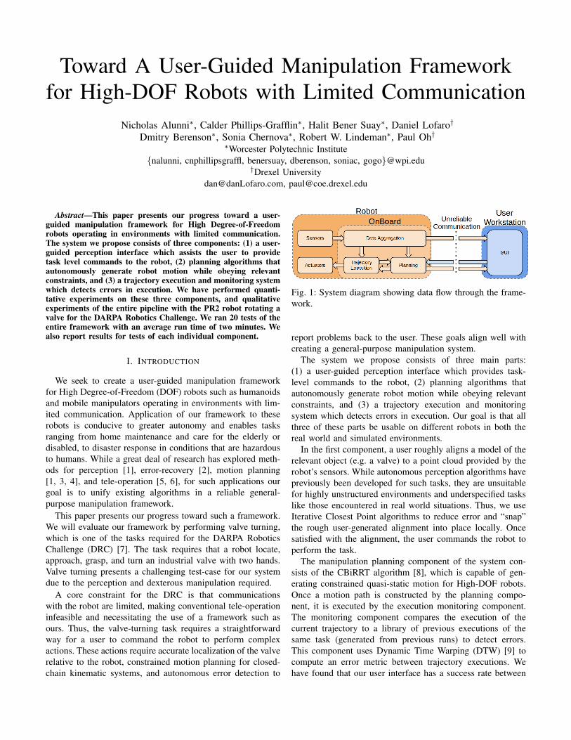
(a) Misaligned Interactive Marker (b) Auto-aligned InteractiveMarker
Fig. 2: Iterative Closest Point being used to align an objectin RVIZ. (a) the object before ICP has been run, (b) the finaltranslation after ICP has finished.
clouds reduce the data needs by nearly 90%, and objectproximity information provides an even greater reduction.
B. User Interface
Due to the difficulty of autonomous perception, a graphicaluser interface (GUI) was created to aid the detection of objects.Using the GUI, as shown in Figure 2a, the user manipulatesan interactive marker [19] to hint at an object’s location.Object alignment is performed using the Iterative ClosestPoint (ICP) algorithm which minimizes the error betweentwo specified groups of points. ICP “snaps” a given inputto the target world, as shown in Figure 2b, by iterativelycomputing the transformation between the two groups ofpoints. Larger transformations can be found by increasing thenumber of iterations performed. To decrease computation time,a bounding box is used to extract a subset of the point cloud.For our testing, the point cloud from the robot is generatedusing an ASUS Xtion RGBD camera.
In addition to user input and feedback, the GUI controls theflow of data over the unreliable link to the robot. Data fromthe robot is only transmitted when specifically requested tominimize communication. This architecture takes advantageof the assumption that the robot inhabits a largely staticenvironment, such as the DRC’s valve turning task, while stillremaining suitable for use in more dynamic environments.
C. Planning
The planning package plans trajectories for high degree offreedom robots so that they can perform object manipulation.The initial configuration of the robot is critical to manipulationbecause the robot must be able to:(1) reach and manipulate the object for the entirety of thedesired trajectory,(2) maintain balance during execution,(3) avoid self-collisions and collisions with the environment
Motion planning is provided by the Constrained BiDirec-tional Rapidly-exploring Random Tree (CBiRRT), an effi-cient and probabilistically complete manipulation planningsuite. CBiRRT consists of three main components: constraintrepresentation, constraint-satisfaction, and a general planning
algorithm. For full details of CBiRRT and its implementation,see [8].
D. Trajectory Execution
The trajectory execution package executes a planned tra-jectory and detects errors encountered during execution. Forthis error detection, trajectories are recorded during executionusing only the data available from joint encoders. No othercontextual data, such as the planned trajectory or the pose ofthe object being manipulated, is required.
Error in trajectory execution is identified by using thedynamic programming technique Dynamic Time Warping(DTW) to match executed trajectories against a library ofknown successful and unsuccessful trajectories. DTW iter-atively calculates the best alignment between elements oftwo or more time sequenced data [9] and produces a costmetric that quantitatively represents the similarity of thosesequences to either the successful or unsuccessful class, whichfacilitates error detection during execution. To account fortrajectories significantly different from those in the library,cases in which the computed DTW cost metric is greater thanan experimentally-determined threshold can be automaticallyidentified as error conditions.
This method of error detection using DTW is ideal as itrequires no complex visual feedback and no special sensors,and is thus applicable to a wide range of robots using only thedata already available from basic joint encoders. In particular,this method is well-suited for the DRC where it may notbe possible to determine the state of the valve though othermeans. For our testing, we used this approach to determine ifthe valve manipulated by the PR2 was successfully turned.
IV. FRAMEWORK VALIDATION
The framework we have developed allows for a user tohint at the location of an object in the world and have therobot approach and manipulate the object. In order to performthis action the pose of the object needs to be determined, atrajectory generated to manipulate it from a start position, andfinally the trajectory must be monitored for errors. Quantitativeexperiments were performed on the three aforementionedcomponents of the architecture, and qualitative experimentswere run with the PR2 robot turning a wheel in both simulationand the real world. Additionally, we report on preliminaryvalidation experiments performed using the Hubo humanoidrobot.
A. Valve Alignment
To enable semi-automated testing, the GUI provides anoption to automatically generate an object alignment witha configurable amount of noise. This testing configurationincludes the number of tests to run, a maximum amountof translation error, and a maximum amount of rotationalerror. We used the semi-automated tester to evaluate the valvealignment system by randomly perturbing the valve’s position.A simulated user guess error is calculated by adding thetotal translation offset in cm to the total quaternion angle
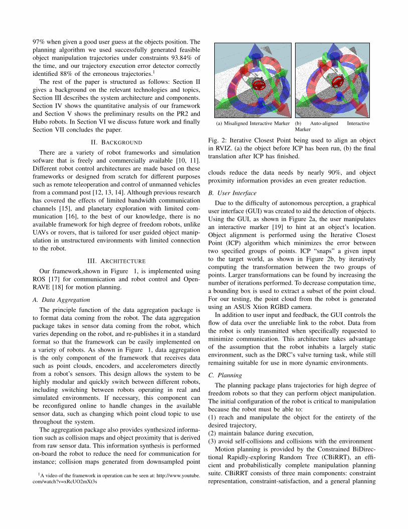
Fig. 4: Success rate (final error less than .3 units) of IterativeClosest Point to find the actual valve position given a randomlygenerated perturbation in the user’s estimated position.
offset in degrees. The true position of the valve is denotedas Vo = [Xo, Yo, Zo] and the guessed position of the valve isdenoted as Vg = [Xg, Yg, Zg]. The total translation value Et
is calculated as the euclidean distance between the two points.Each valve’s pose also contains a quaternion that representsits orientation in space. The difference in angle between thequaternion representing the valve’s position and the guessedposition is represented.
Eq = arccos(2∗((xo∗xg)+(yo∗yg)+(zo∗zg)+(wo∗wg))2−1)
(1)Finally, the user guess error is calculated by the sum of
the translational error and rotational error, and is denoted byE = Et + Eq .
Figure 4 shows the success rate of 450 sample alignmentswith random perturbations, where success is defined as a finalerror of less than .3 units. The ”user guess error” is theamount of error that was present when the semi-automatedtester requested ICP to align the valve to the point cloud. Wequalitatively categorized the results through experimentation.One to five error units is considered a good user guess, sixto ten error units is considered an acceptable user guess, andeleven to fifteen error units is a ”poor” user guess. ICP wascapable of matching the interactive marker to the point cloud97% of the time for a good guess, 79% of the time for anacceptable guess, and 58% of the time for a poor guess. Thenumber of ICP iterations, 500, remained constant throughoutall tests. The number of iterations was determined so that ICPreturns with a new valve alignment in under one second. Thenumber of iterations ICP runs can be increased, allowing largertransformations to be found at the cost of longer runtime.
B. Planning
We tested the CBiRRT trajectory planner’s performancewith the constraints described in Section III under differentsensing disturbances of the object (in this case, the valve). Wefirst fixed the position of the object to a point in space, wherewe knew the planner was able to succeed. We then addedrandom translation and rotation perturbations to the transform
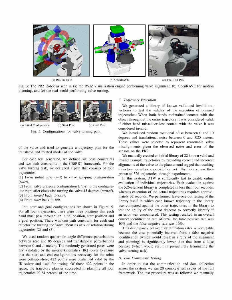
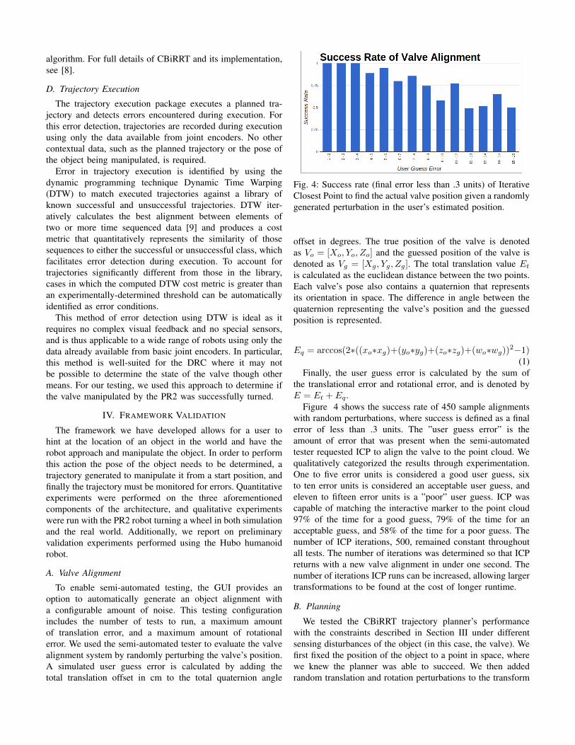
(a) PR2 in RViz (b) OpenRAVE (c) The Real PR2
Fig. 3: The PR2 Robot as seen in (a) the RVIZ visualization engine performing valve alignment, (b) OpenRAVE for motionplanning, and (c) the real world performing valve turning.
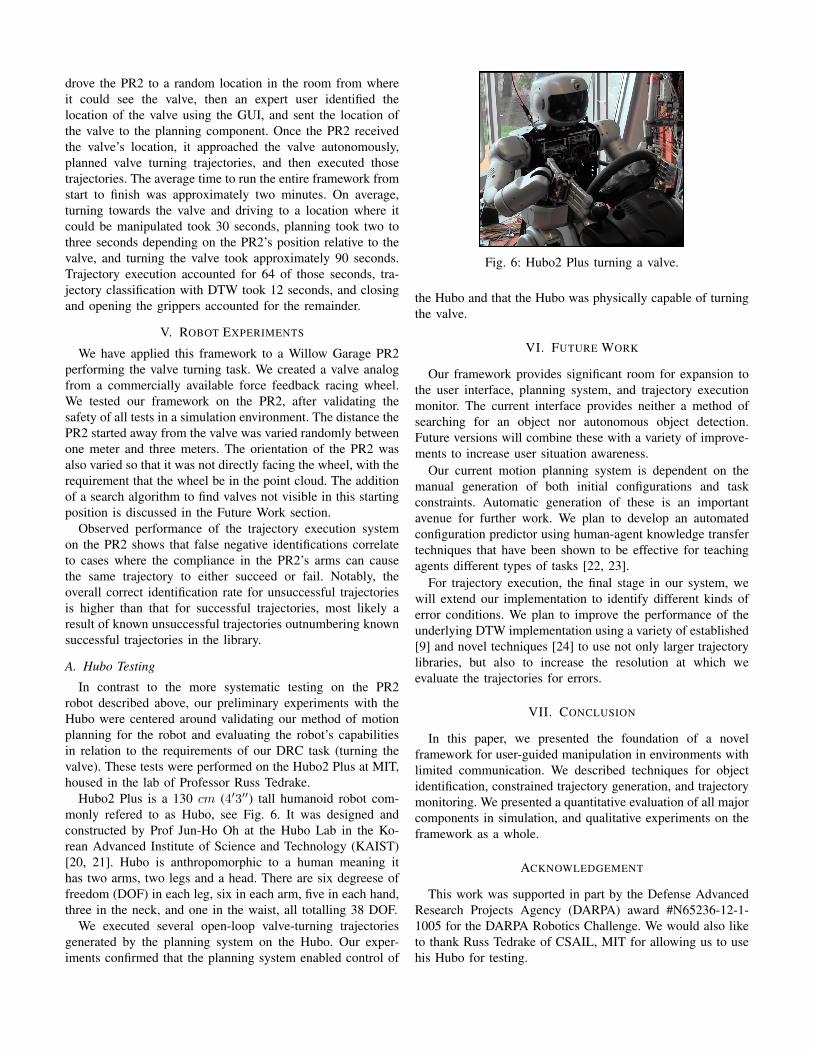
(a) Initial Configuration (b) Start Pose (c) Goal Pose
Fig. 5: Configurations for valve turning path.
of the valve and tried to generate a trajectory plan for thetranslated and rotated model of the valve.
For each test generated, we defined six pose constraintsand two path constraints in the CBiRRT framework. For thevalve turning task, we designed a path that consists of fourtrajectories:(1) From initial pose (init) to valve grasping configuration(start),(2) From valve grasping configuration (start) to the configura-tion right after clockwise turning the valve 45 degrees (turned),(3) From turned back to start,(4) From start back to init.
Init, start and goal configurations are shown in Figure. 5.For all four trajectories, there were three positions that eachhand must pass through; an initial position, start position anda goal position. There was one path constraint for each endeffector for turning the valve about its axis of rotation duringtrajectories (2) and (3).
We used random quaternion angle difference perturbationsbetween zero and 85 degrees and translational perturbationsbetween 0 and .1 meters. The randomly generated poses werefirst validated by the inverse kinematics (IK) solver to ensurethat the start and end configurations necessary for the robotwere collision-free; 422 points were confirmed valid by theIK solver and used for testing. Of those 422 points in thespace, the trajectory planner succeeded in planning all fourtrajectories 93.84 percent of the time.
C. Trajectory Execution
We generated a library of known valid and invalid tra-jectories to test the validity of the execution of plannedtrajectories. When both hands maintained contact with theobject throughout the entire trajectory it was considered valid,if either hand missed or lost contact with the valve it wasconsidered invalid.
We introduced random rotational noise between 0 and 10degrees and translational noise between 0 and .025 meters.These values were selected to represent reasonable valvemisalignments given the observed noise and error of thesensors on the PR2.
We manually created an initial library of 22 known valid andinvalid example trajectories by providing correct and incorrectalignments of the valve to the planner, and tagged the resultingtrajectory as either successful or not. The library was thengrown to 526 trajectories through experiments.
In this system, DTW is sufficiently fast to enable onlineevaluation of individual trajectories. Each evaluation againstthe 526-element library is completed in less than four seconds,whereas execution of the actual trajectories requires approxi-mately 32 seconds. We performed leave-one-out testing of thelibrary itself in which each known trajectory in the librarywas compared against the other trajectories in the library totest the ability of the error detector to correctly identify ifan error was encountered. This testing resulted in an overallcorrect identification rate of 88%, the false positive rate was10% and the false negative rate was 16%.
This discrepancy between identification rates is acceptablebecause the cost potentially incurred from a false negativeidentification (which would result in a retry of the alignmentand planning) is significantly lower than that from a falsepositive (which would result in prematurely terminating thevalve turning task).
D. Full Framework Testing
In order to test the communication and data collectionacross the system, we ran 20 complete test cycles of the fullframework. The test procedure was as follows: we manually
drove the PR2 to a random location in the room from whereit could see the valve, then an expert user identified thelocation of the valve using the GUI, and sent the location ofthe valve to the planning component. Once the PR2 receivedthe valve’s location, it approached the valve autonomously,planned valve turning trajectories, and then executed thosetrajectories. The average time to run the entire framework fromstart to finish was approximately two minutes. On average,turning towards the valve and driving to a location where itcould be manipulated took 30 seconds, planning took two tothree seconds depending on the PR2’s position relative to thevalve, and turning the valve took approximately 90 seconds.Trajectory execution accounted for 64 of those seconds, tra-jectory classification with DTW took 12 seconds, and closingand opening the grippers accounted for the remainder.
V. ROBOT EXPERIMENTS
We have applied this framework to a Willow Garage PR2performing the valve turning task. We created a valve analogfrom a commercially available force feedback racing wheel.We tested our framework on the PR2, after validating thesafety of all tests in a simulation environment. The distance thePR2 started away from the valve was varied randomly betweenone meter and three meters. The orientation of the PR2 wasalso varied so that it was not directly facing the wheel, with therequirement that the wheel be in the point cloud. The additionof a search algorithm to find valves not visible in this startingposition is discussed in the Future Work section.
Observed performance of the trajectory execution systemon the PR2 shows that false negative identifications correlateto cases where the compliance in the PR2’s arms can causethe same trajectory to either succeed or fail. Notably, theoverall correct identification rate for unsuccessful trajectoriesis higher than that for successful trajectories, most likely aresult of known unsuccessful trajectories outnumbering knownsuccessful trajectories in the library.
A. Hubo Testing
In contrast to the more systematic testing on the PR2robot described above, our preliminary experiments with theHubo were centered around validating our method of motionplanning for the robot and evaluating the robot’s capabilitiesin relation to the requirements of our DRC task (turning thevalve). These tests were performed on the Hubo2 Plus at MIT,housed in the lab of Professor Russ Tedrake.
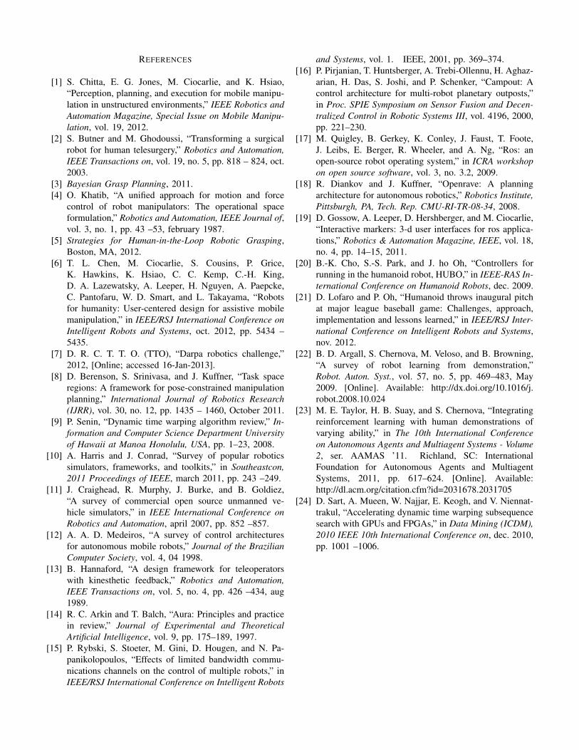
Hubo2 Plus is a 130 cm (4′3′′) tall humanoid robot com-monly refered to as Hubo, see Fig. 6. It was designed andconstructed by Prof Jun-Ho Oh at the Hubo Lab in the Ko-rean Advanced Institute of Science and Technology (KAIST)[20, 21]. Hubo is anthropomorphic to a human meaning ithas two arms, two legs and a head. There are six degreese offreedom (DOF) in each leg, six in each arm, five in each hand,three in the neck, and one in the waist, all totalling 38 DOF.
We executed several open-loop valve-turning trajectoriesgenerated by the planning system on the Hubo. Our exper-iments confirmed that the planning system enabled control of
Fig. 6: Hubo2 Plus turning a valve.
the Hubo and that the Hubo was physically capable of turningthe valve.
VI. FUTURE WORK
Our framework provides significant room for expansion tothe user interface, planning system, and trajectory executionmonitor. The current interface provides neither a method ofsearching for an object nor autonomous object detection.Future versions will combine these with a variety of improve-ments to increase user situation awareness.
Our current motion planning system is dependent on themanual generation of both initial configurations and taskconstraints. Automatic generation of these is an importantavenue for further work. We plan to develop an automatedconfiguration predictor using human-agent knowledge transfertechniques that have been shown to be effective for teachingagents different types of tasks [22, 23].
For trajectory execution, the final stage in our system, wewill extend our implementation to identify different kinds oferror conditions. We plan to improve the performance of theunderlying DTW implementation using a variety of established[9] and novel techniques [24] to use not only larger trajectorylibraries, but also to increase the resolution at which weevaluate the trajectories for errors.
VII. CONCLUSION
In this paper, we presented the foundation of a novelframework for user-guided manipulation in environments withlimited communication. We described techniques for objectidentification, constrained trajectory generation, and trajectorymonitoring. We presented a quantitative evaluation of all majorcomponents in simulation, and qualitative experiments on theframework as a whole.
ACKNOWLEDGEMENT
This work was supported in part by the Defense AdvancedResearch Projects Agency (DARPA) award #N65236-12-1-1005 for the DARPA Robotics Challenge. We would also liketo thank Russ Tedrake of CSAIL, MIT for allowing us to usehis Hubo for testing.
REFERENCES
[1] S. Chitta, E. G. Jones, M. Ciocarlie, and K. Hsiao,“Perception, planning, and execution for mobile manipu-lation in unstructured environments,” IEEE Robotics andAutomation Magazine, Special Issue on Mobile Manipu-lation, vol. 19, 2012.
[2] S. Butner and M. Ghodoussi, “Transforming a surgicalrobot for human telesurgery,” Robotics and Automation,IEEE Transactions on, vol. 19, no. 5, pp. 818 – 824, oct.2003.
[3] Bayesian Grasp Planning, 2011.[4] O. Khatib, “A unified approach for motion and force
control of robot manipulators: The operational spaceformulation,” Robotics and Automation, IEEE Journal of,vol. 3, no. 1, pp. 43 –53, february 1987.
[5] Strategies for Human-in-the-Loop Robotic Grasping,Boston, MA, 2012.
[6] T. L. Chen, M. Ciocarlie, S. Cousins, P. Grice,K. Hawkins, K. Hsiao, C. C. Kemp, C.-H. King,D. A. Lazewatsky, A. Leeper, H. Nguyen, A. Paepcke,C. Pantofaru, W. D. Smart, and L. Takayama, “Robotsfor humanity: User-centered design for assistive mobilemanipulation,” in IEEE/RSJ International Conference onIntelligent Robots and Systems, oct. 2012, pp. 5434 –5435.
[7] D. R. C. T. T. O. (TTO), “Darpa robotics challenge,”2012, [Online; accessed 16-Jan-2013].
[8] D. Berenson, S. Srinivasa, and J. Kuffner, “Task spaceregions: A framework for pose-constrained manipulationplanning,” International Journal of Robotics Research(IJRR), vol. 30, no. 12, pp. 1435 – 1460, October 2011.
[9] P. Senin, “Dynamic time warping algorithm review,” In-formation and Computer Science Department Universityof Hawaii at Manoa Honolulu, USA, pp. 1–23, 2008.
[10] A. Harris and J. Conrad, “Survey of popular roboticssimulators, frameworks, and toolkits,” in Southeastcon,2011 Proceedings of IEEE, march 2011, pp. 243 –249.
[11] J. Craighead, R. Murphy, J. Burke, and B. Goldiez,“A survey of commercial open source unmanned ve-hicle simulators,” in IEEE International Conference onRobotics and Automation, april 2007, pp. 852 –857.
[12] A. A. D. Medeiros, “A survey of control architecturesfor autonomous mobile robots,” Journal of the BrazilianComputer Society, vol. 4, 04 1998.
[13] B. Hannaford, “A design framework for teleoperatorswith kinesthetic feedback,” Robotics and Automation,IEEE Transactions on, vol. 5, no. 4, pp. 426 –434, aug1989.
[14] R. C. Arkin and T. Balch, “Aura: Principles and practicein review,” Journal of Experimental and TheoreticalArtificial Intelligence, vol. 9, pp. 175–189, 1997.
[15] P. Rybski, S. Stoeter, M. Gini, D. Hougen, and N. Pa-panikolopoulos, “Effects of limited bandwidth commu-nications channels on the control of multiple robots,” inIEEE/RSJ International Conference on Intelligent Robots
and Systems, vol. 1. IEEE, 2001, pp. 369–374.[16] P. Pirjanian, T. Huntsberger, A. Trebi-Ollennu, H. Aghaz-
arian, H. Das, S. Joshi, and P. Schenker, “Campout: Acontrol architecture for multi-robot planetary outposts,”in Proc. SPIE Symposium on Sensor Fusion and Decen-tralized Control in Robotic Systems III, vol. 4196, 2000,pp. 221–230.
[17] M. Quigley, B. Gerkey, K. Conley, J. Faust, T. Foote,J. Leibs, E. Berger, R. Wheeler, and A. Ng, “Ros: anopen-source robot operating system,” in ICRA workshopon open source software, vol. 3, no. 3.2, 2009.
[18] R. Diankov and J. Kuffner, “Openrave: A planningarchitecture for autonomous robotics,” Robotics Institute,Pittsburgh, PA, Tech. Rep. CMU-RI-TR-08-34, 2008.
[19] D. Gossow, A. Leeper, D. Hershberger, and M. Ciocarlie,“Interactive markers: 3-d user interfaces for ros applica-tions,” Robotics & Automation Magazine, IEEE, vol. 18,no. 4, pp. 14–15, 2011.
[20] B.-K. Cho, S.-S. Park, and J. ho Oh, “Controllers forrunning in the humanoid robot, HUBO,” in IEEE-RAS In-ternational Conference on Humanoid Robots, dec. 2009.
[21] D. Lofaro and P. Oh, “Humanoid throws inaugural pitchat major league baseball game: Challenges, approach,implementation and lessons learned,” in IEEE/RSJ Inter-national Conference on Intelligent Robots and Systems,nov. 2012.
[22] B. D. Argall, S. Chernova, M. Veloso, and B. Browning,“A survey of robot learning from demonstration,”Robot. Auton. Syst., vol. 57, no. 5, pp. 469–483, May2009. [Online]. Available: http://dx.doi.org/10.1016/j.robot.2008.10.024
[23] M. E. Taylor, H. B. Suay, and S. Chernova, “Integratingreinforcement learning with human demonstrations ofvarying ability,” in The 10th International Conferenceon Autonomous Agents and Multiagent Systems - Volume2, ser. AAMAS ’11. Richland, SC: InternationalFoundation for Autonomous Agents and MultiagentSystems, 2011, pp. 617–624. [Online]. Available:http://dl.acm.org/citation.cfm?id=2031678.2031705
[24] D. Sart, A. Mueen, W. Najjar, E. Keogh, and V. Niennat-trakul, “Accelerating dynamic time warping subsequencesearch with GPUs and FPGAs,” in Data Mining (ICDM),2010 IEEE 10th International Conference on, dec. 2010,pp. 1001 –1006.