Embed Size (px)
Citation preview
Abstract
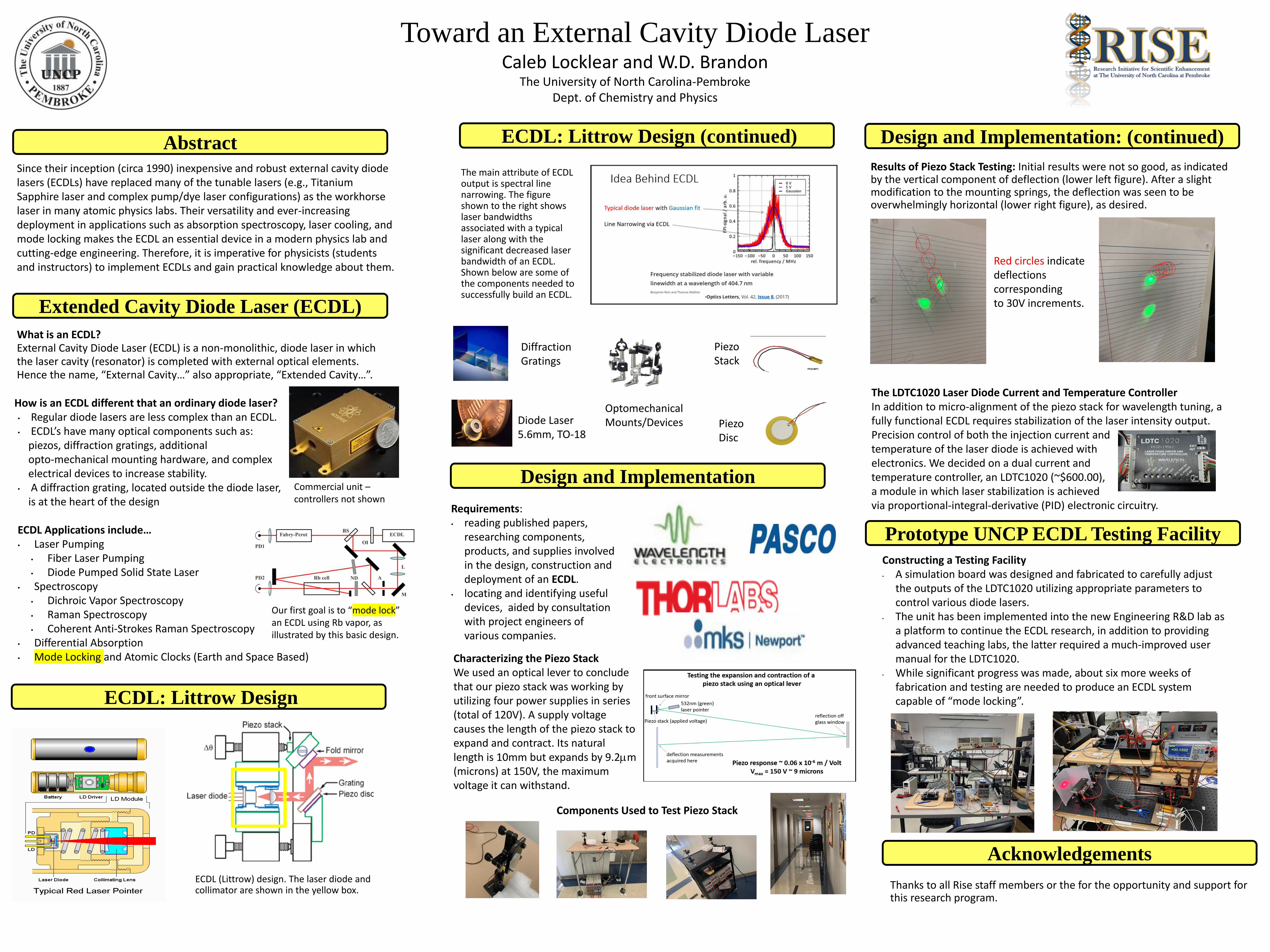
Toward an External Cavity Diode LaserCaleb Locklear and W.D. Brandon
The University of North Carolina-PembrokeDept. of Chemistry and Physics
Since their inception (circa 1990) inexpensive and robust external cavity diode lasers (ECDLs) have replaced many of the tunable lasers (e.g., Titanium Sapphire laser and complex pump/dye laser configurations) as the workhorse laser in many atomic physics labs. Their versatility and ever-increasing deployment in applications such as absorption spectroscopy, laser cooling, and mode locking makes the ECDL an essential device in a modern physics lab and cutting-edge engineering. Therefore, it is imperative for physicists (students and instructors) to implement ECDLs and gain practical knowledge about them.
Extended Cavity Diode Laser (ECDL)
What is an ECDL? External Cavity Diode Laser (ECDL) is a non-monolithic, diode laser in which the laser cavity (resonator) is completed with external optical elements. Hence the name, “External Cavity…” also appropriate, “Extended Cavity…”.
How is an ECDL different that an ordinary diode laser?• Regular diode lasers are less complex than an ECDL.• ECDL’s have many optical components such as:
piezos, diffraction gratings, additional opto-mechanical mounting hardware, and complex electrical devices to increase stability.
• A diffraction grating, located outside the diode laser, is at the heart of the design
ECDL Applications include…• Laser Pumping
• Fiber Laser Pumping• Diode Pumped Solid State Laser
• Spectroscopy• Dichroic Vapor Spectroscopy• Raman Spectroscopy• Coherent Anti-Strokes Raman Spectroscopy
• Differential Absorption• Mode Locking and Atomic Clocks (Earth and Space Based)
Commercial unit –controllers not shown
ECDL: Littrow Design
ECDL (Littrow) design. The laser diode and collimator are shown in the yellow box.
Requirements:• reading published papers,
researching components, products, and supplies involved in the design, construction and deployment of an ECDL.
• locating and identifying useful devices, aided by consultation with project engineers of various companies.
Diffraction Gratings
Diode Laser 5.6mm, TO-18
Piezo Stack
Piezo Disc
OptomechanicalMounts/Devices
Design and Implementation
Characterizing the Piezo StackWe used an optical lever to conclude that our piezo stack was working by utilizing four power supplies in series (total of 120V). A supply voltage causes the length of the piezo stack to expand and contract. Its natural length is 10mm but expands by 9.2mm (microns) at 150V, the maximum voltage it can withstand.
Results of Piezo Stack Testing: Initial results were not so good, as indicated by the vertical component of deflection (lower left figure). After a slight modification to the mounting springs, the deflection was seen to be overwhelmingly horizontal (lower right figure), as desired.
Red circles indicatedeflections corresponding to 30V increments.
The LDTC1020 Laser Diode Current and Temperature ControllerIn addition to micro-alignment of the piezo stack for wavelength tuning, a fully functional ECDL requires stabilization of the laser intensity output. Precision control of both the injection current and temperature of the laser diode is achieved with electronics. We decided on a dual current and temperature controller, an LDTC1020 (~$600.00), a module in which laser stabilization is achieved via proportional-integral-derivative (PID) electronic circuitry.
Constructing a Testing Facility• A simulation board was designed and fabricated to carefully adjust
the outputs of the LDTC1020 utilizing appropriate parameters to control various diode lasers.
• The unit has been implemented into the new Engineering R&D lab as a platform to continue the ECDL research, in addition to providing advanced teaching labs, the latter required a much-improved user manual for the LDTC1020.
• While significant progress was made, about six more weeks of fabrication and testing are needed to produce an ECDL system capable of “mode locking”.
Acknowledgements
Our first goal is to “mode lock” an ECDL using Rb vapor, as illustrated by this basic design.
The main attribute of ECDL output is spectral line narrowing. The figure shown to the right showslaser bandwidths associated with a typical laser along with the significant decreased laser bandwidth of an ECDL. Shown below are some of the components needed to successfully build an ECDL.
Components Used to Test Piezo Stack
ECDL: Littrow Design (continued) Design and Implementation: (continued)
Prototype UNCP ECDL Testing Facility
Thanks to all Rise staff members or the for the opportunity and support for this research program.


![Tunable High-Power External-Cavity GaN Diode Laser Systems ... · high-power GaN diode lasers and make the lasers tunable [13, 14]. The laser systems devel-oped based on the irst](https://img.pdfslide.net/doc/110x75/5f664cfd4c245d69d0474c4f/tunable-high-power-external-cavity-gan-diode-laser-systems-high-power-gan-diode.jpg)


![arXiv:1610.01240v2 [physics.optics] 14 Oct 2016 · Spontaneous Emission and Light Extraction Enhancement of Light Emitting Diode Using Partially-Reflecting Metasurface Cavity (PRMC)](https://img.pdfslide.net/doc/110x75/5aef60547f8b9a8b4c8c3782/arxiv161001240v2-14-oct-2016-emission-and-light-extraction-enhancement-of.jpg)