Embed Size (px)
Citation preview
1
towards
a successful
completion
Lars SørumChief Scientist, SINTEF Energy
Research
Coordinator
of
NextGenBioWaste
2
What
is NextGenBioWaste
really
about?
•
The
process–
Combustion
•
Fuels–
Municipal
Solid Waste
(MSW)
–
Biomass•
Type of
plants
–
Grate
furnaces
(waste)–
Fluidised
bed furnaces
(biomass
and waste)
–
Pulverized
fuels
furnaces
(biomass)•
Type of
activities
–
Demonstration
activities
(80% of
budget)–
R&D (20 % of
budget)
3
55 deliverables!11 deliverables with due date in january and february 2008
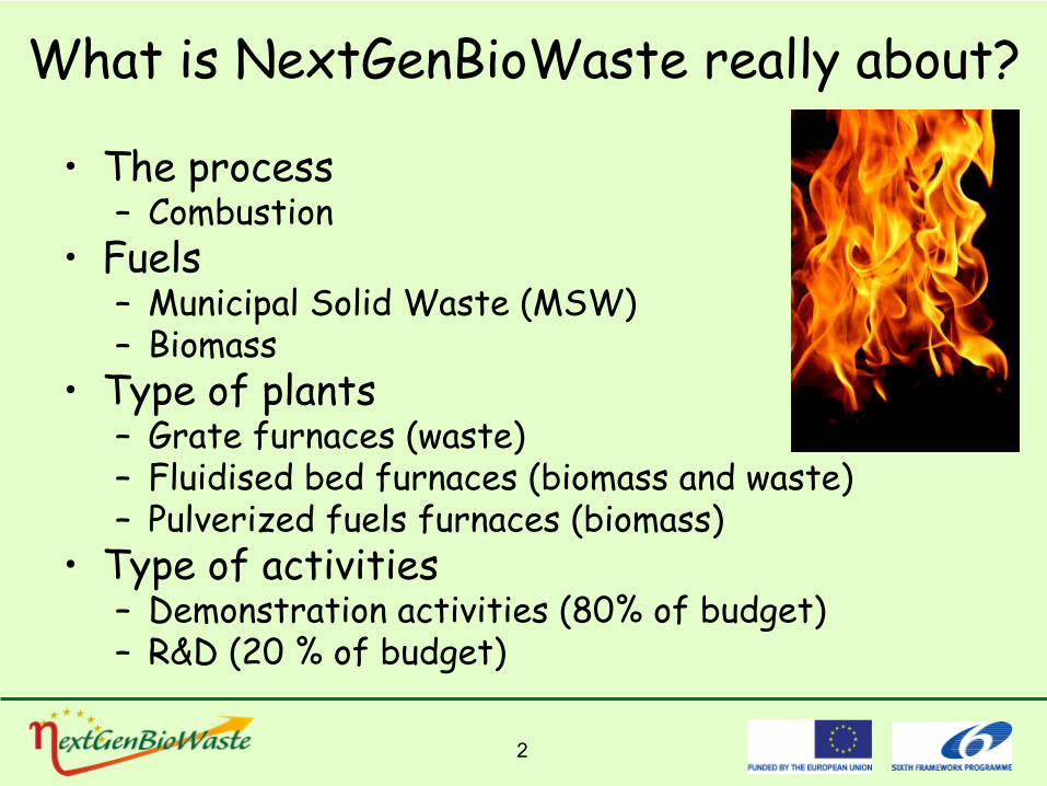
The
scope
of
4
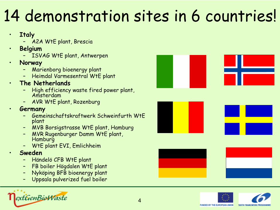
14 demonstration
sites
in 6 countries!•
Italy–
A2A WtE
plant, Brescia•
Belgium–
ISVAG WtE
plant, Antwerpen •
Norway–
Marienborg
bioenergy
plant–
Heimdal Varmesentral WtE
plant•
The
Netherlands–
High
efficiency
waste
fired
power
plant, Amsterdam
–
AVR WtE
plant, Rozenburg•
Germany–
Gemeinschaftskraftwerk
Schweinfurth
WtE
plant
–
MVB Borsigstrasse
WtE
plant, Hamburg–
MVR Rugenburger
Damm WtE
plant, Hamburg
–
WtE
plant EVI, Emlichheim•
Sweden–
Händelö
CFB WtE
plant–
FB boiler
Högdalen
WtE
plant–
Nyköping
BFB bioenergy
plant–
Uppsala pulverized
fuel
boiler
5
1.
Increase the electric efficiency for waste to energy plants from 22% to 30% (gross generated)
2.
Double the lifetime of heat exchanger components at existing steam temperatures
3.
Increase the electric efficiency for biomass combustion plants from 33% to 35%, while making the systems more cost-effective by the use of more low-grade fuels
4.
Lower the fuel cost at least 1 mill.€/year for a 100 MWthbiomass combustion plant
5.
Enable technologies for upgrading of bottom ash, thus, enabling the utility companies to valorise from 70% of their bottom ashes for civil engineering purposes
NextGenBioWaste’s
Targets
6
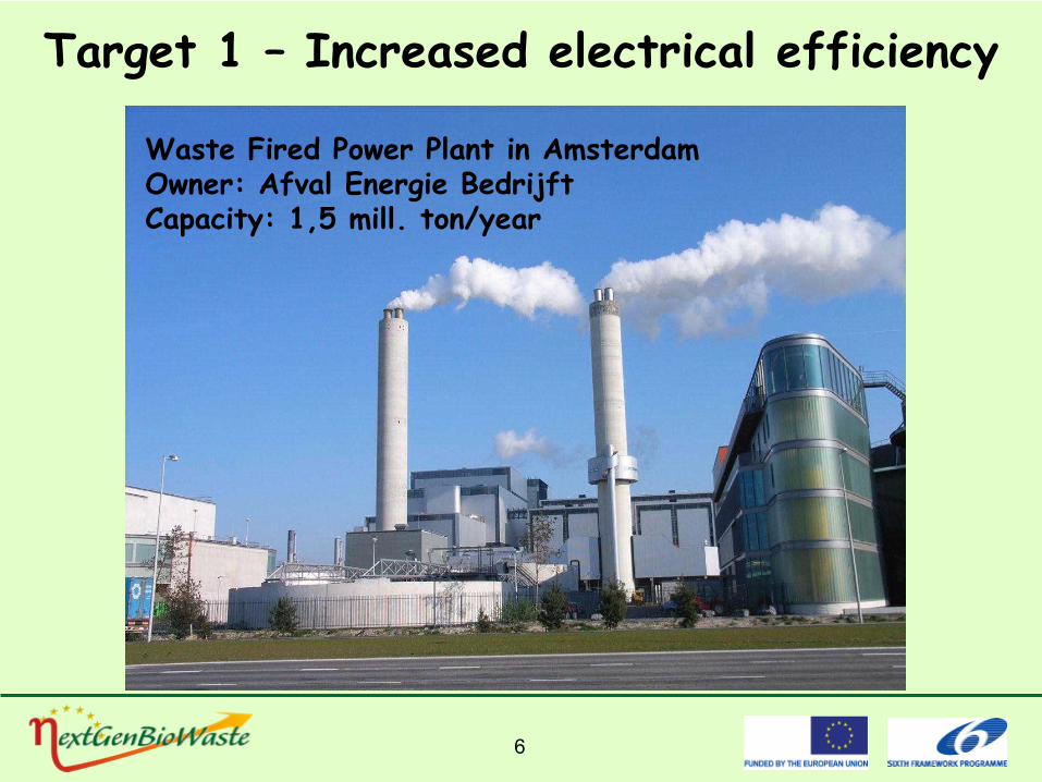
Target 1 –
Increased
electrical
efficiency
Waste
Fired
Power
Plant in AmsterdamOwner: Afval
Energie
Bedrijft
Capacity: 1,5 mill. ton/year
7
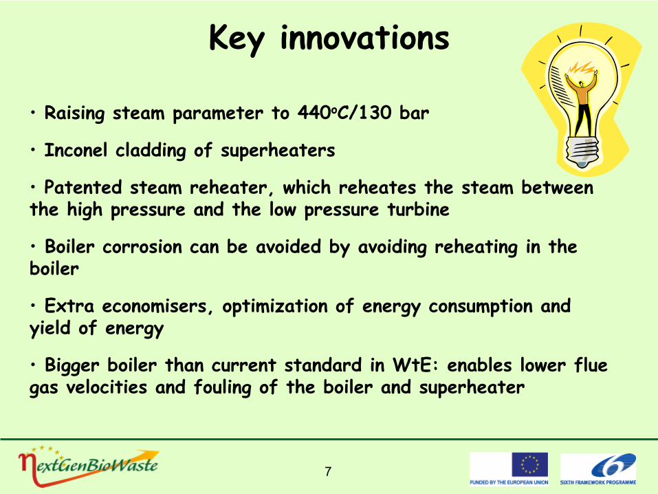
Key
innovations
• Raising
steam
parameter to 440oC/130 bar
• Inconel
cladding
of
superheaters
•
Patented
steam
reheater, which
reheates
the
steam
between the
high
pressure
and the
low
pressure
turbine
•
Boiler
corrosion
can
be avoided
by avoiding
reheating
in
the boiler
•
Extra
economisers, optimization
of
energy
consumption
and yield
of
energy
•
Bigger
boiler
than
current
standard in WtE: enables
lower
flue gas velocities
and fouling
of
the
boiler
and superheater
8
0,0%
10,0%
20,0%
30,0%
40,0%
1-0
3-09
8-0
3-09
15-
03-0
9
22-
03-0
9
29-
03-0
9
5-0
4-09
12-
04-0
9
19-
04-0
9
26-
04-0
9
3-0
5-09
10-
05-0
9
17-
05-0
9
24-
05-0
9
31-
05-0
9
7-0
6-09
14-
06-0
9
21-
06-0
9
28-
06-0
9
5-0
7-09
12-
07-0
9
19-
07-0
9
26-
07-0
9
2-0
8-09
9-0
8-09
16-
08-0
9
23-
08-0
9
30-
08-0
9
6-0
9-09
13-
09-0
9
20-
09-0
9
27-
09-0
9
4-1
0-09
11-
10-0
9
18-
10-0
9
25-
10-0
9
1-1
1-09
8-1
1-09
15-
11-0
9
22-
11-0
9
29-
11-0
9
6-1
2-09
13-
12-0
9
20-
12-0
9
27-
12-0
9
Effic
ienc
y
ηMEP ηMEP montly average Best day of the month
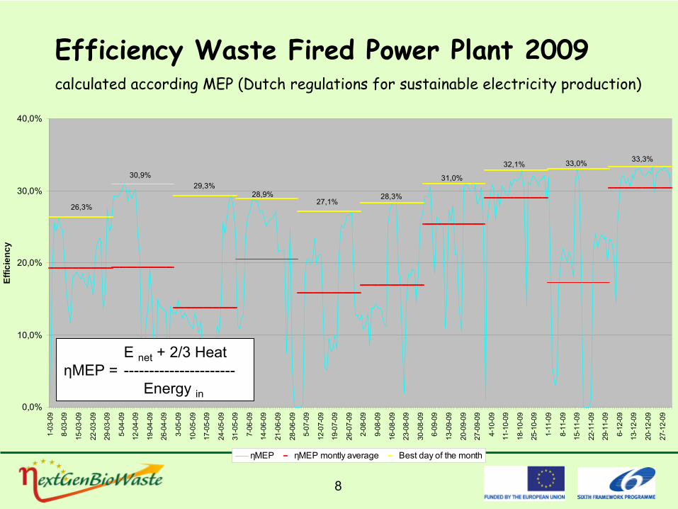
Efficiency Waste Fired Power Plant 2009calculated according MEP (Dutch regulations for sustainable electricity production)
26,3%
30,9%29,3%
28,9%27,1%
28,3%
31,0%
32,1% 33,0% 33,3%
E net
+ 2/3 HeatηMEP
= ----------------------Energy in
9
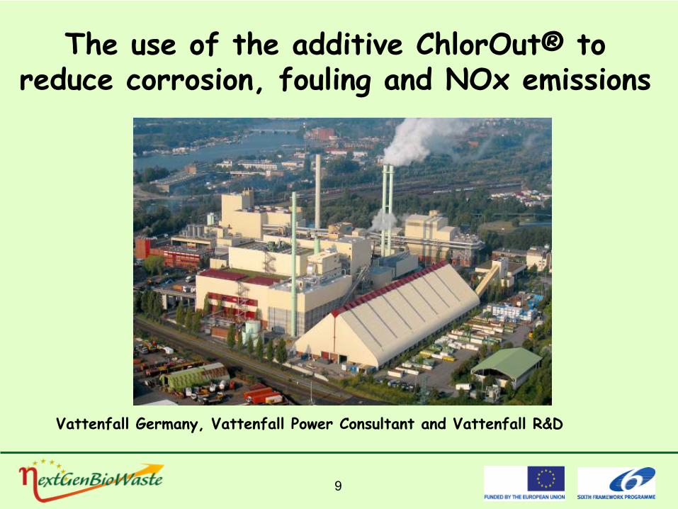
The use of the additive ChlorOut®
to reduce corrosion, fouling and NOx emissions
Vattenfall Germany, Vattenfall Power Consultant and Vattenfall R&D
10
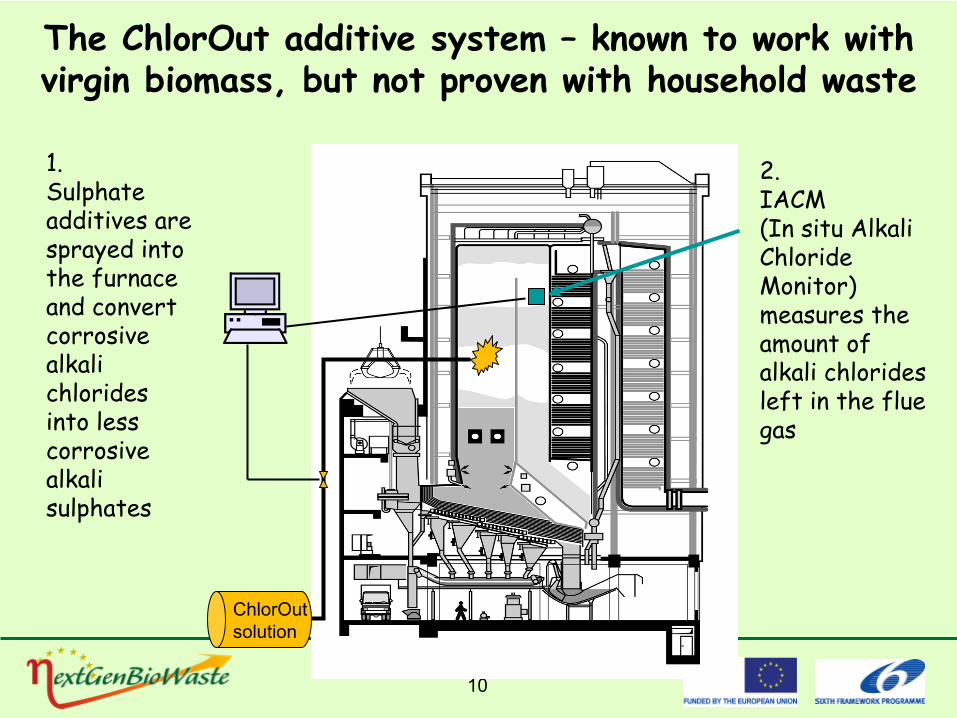
The ChlorOut
additive system –
known to work with virgin biomass, but not proven with household waste
2. IACM
(In situ Alkali Chloride Monitor) measures the amount of alkali chlorides left in the flue gas
ChlorOut solution
1. Sulphate
additives are sprayed into the furnace and convert corrosive alkali chlorides into less corrosive alkali sulphates
11
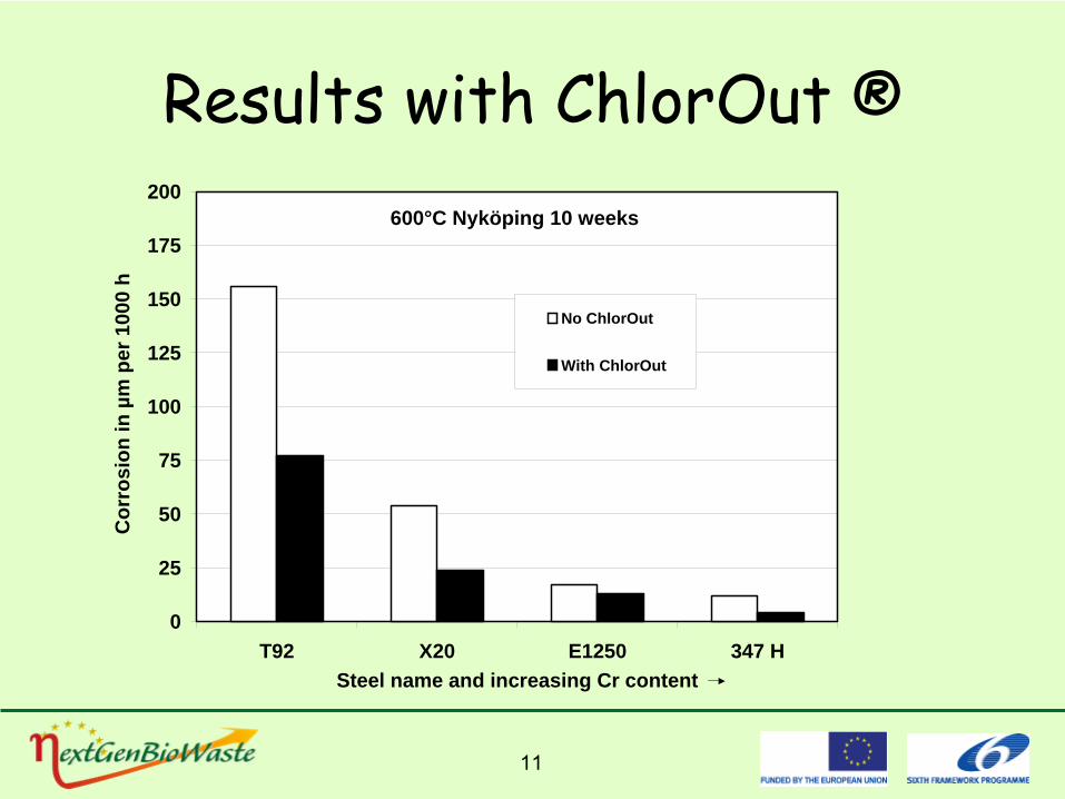
Results with ChlorOut ®
0
25
50
75
100
125
150
175
200
T92 X20 E1250 347 HSteel name and increasing Cr content
Cor
rosi
on in
µm
per
100
0 h
No ChlorOut
With ChlorOut
600°C Nyköping 10 weeks
12
Target 2 –
Doubled
lifetime
of
heat exchangers
•
Results:–
Long-term
tests in waste-wood
boiler
showed
that
using
the
ChlorOut
additive halved
the
corrosion
rates.
–
Short term test using
ChlorOut
on household
waste
combustion
confirm
a
reduction
rate of
more than
50%–
Supporting
information
•
Studies of the initial corrosion rates on both ferritic
and austenitic steels shows a reduction
rate with about 60% •
Reduction rate of more than 75% of the concentration of alkali chlorides in the flue gas
•
Chloride concentration in deposits reduced from ~8% to almost 0!
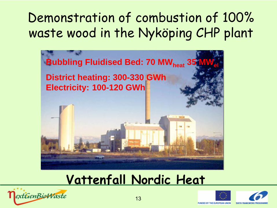
13
Demonstration of combustion of 100% waste wood in the Nyköping
CHP plant
Vattenfall Nordic Heat
Bubbling Fluidised Bed: 70 MWheat 35 MWel
District heating: 300-330 GWh Electricity: 100-120 GWh
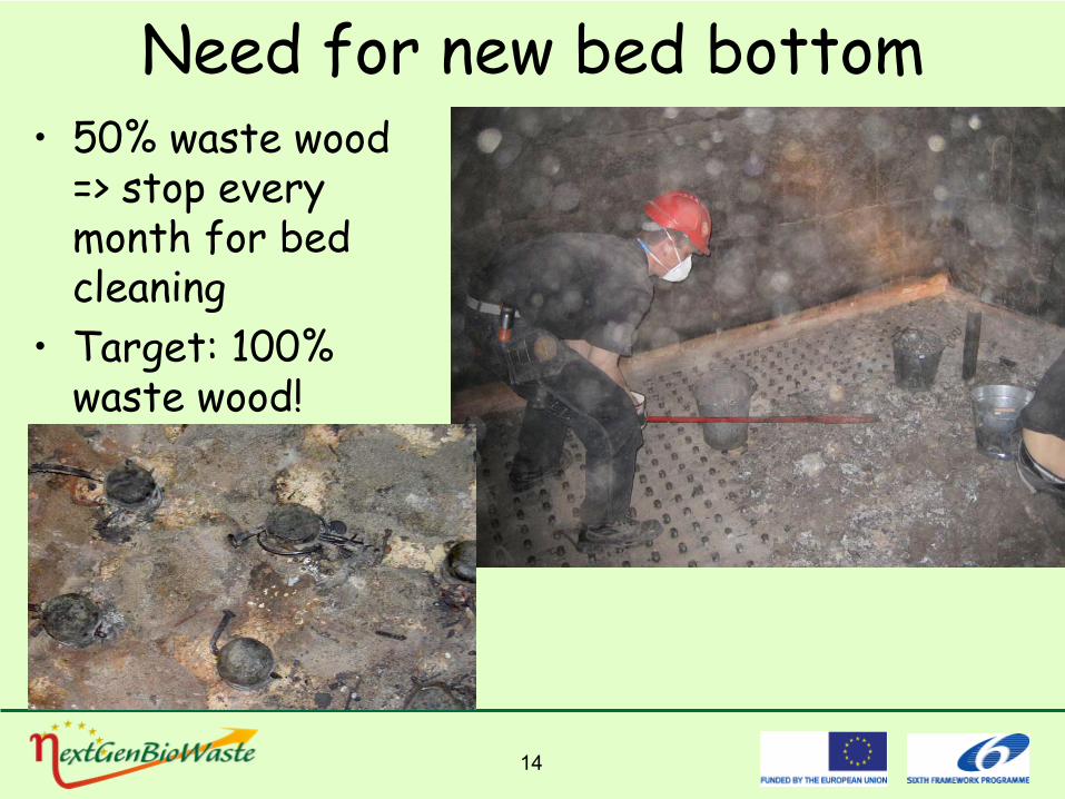
14
Need for new bed bottom •
50% waste wood => stop every month for bed cleaning
•
Target: 100% waste wood!
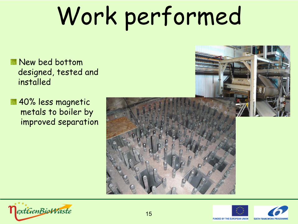
15
Work performedNew bed bottomdesigned, tested
and
installed
40% less magneticmetals
to boiler
by
improved
separation
16
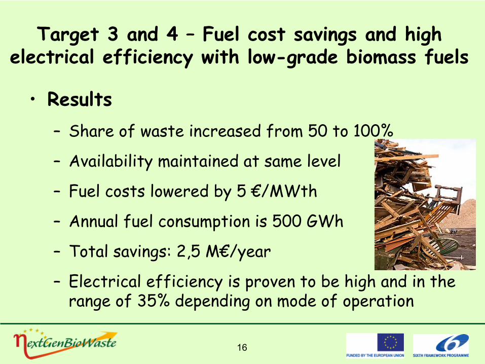
Target 3 and 4 –
Fuel
cost
savings
and high electrical
efficiency
with
low-grade
biomass
fuels
•
Results–
Share
of
waste
increased
from 50 to 100%
–
Availability
maintained
at same level
–
Fuel
costs
lowered
by 5 €/MWth
–
Annual
fuel
consumption
is 500 GWh
–
Total savings: 2,5 M€/year
–
Electrical
efficiency
is proven
to be high
and in the range of
35% depending
on
mode of
operation
17
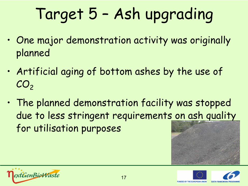
Target 5 – Ash upgrading•
One
major demonstration
activity
was
originally
planned
•
Artificial
aging
of
bottom
ashes
by the
use
of CO2
•
The
planned
demonstration
facility
was
stopped due to less stringent requirements
on
ash
quality
for utilisation
purposes

18
R&D in
19
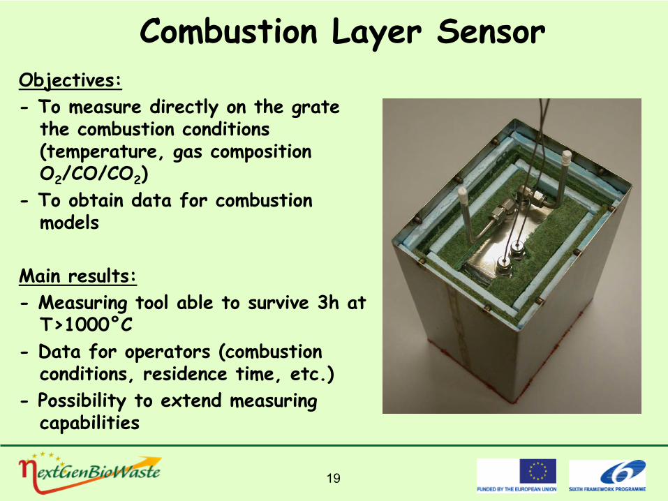
Combustion Layer SensorObjectives:-
To measure directly on the grate the combustion conditions (temperature, gas composition O2
/CO/CO2
)-
To obtain data for combustion models
Main results:-
Measuring tool able to survive 3h at T>1000°C
-
Data for operators (combustion conditions, residence time, etc.)
-
Possibility to extend measuring capabilities

20
Tests made in 8 MSW combustion plants:
-
Rozenburg (NL)/AVR-
Rotterdam (NL)/AVR
-
Amsterdam (NL)/AEB-
Schweinfurt (D)/GKS
-
Prague (CZ)/Municipality-
Brno (CZ)/Municipality
- Twence (NL)/Twence A&E
BV
- Coevorden (NL)/EUROPARK
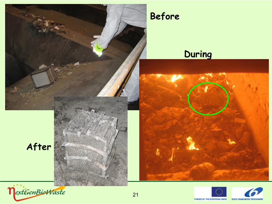
21
Before
During
After
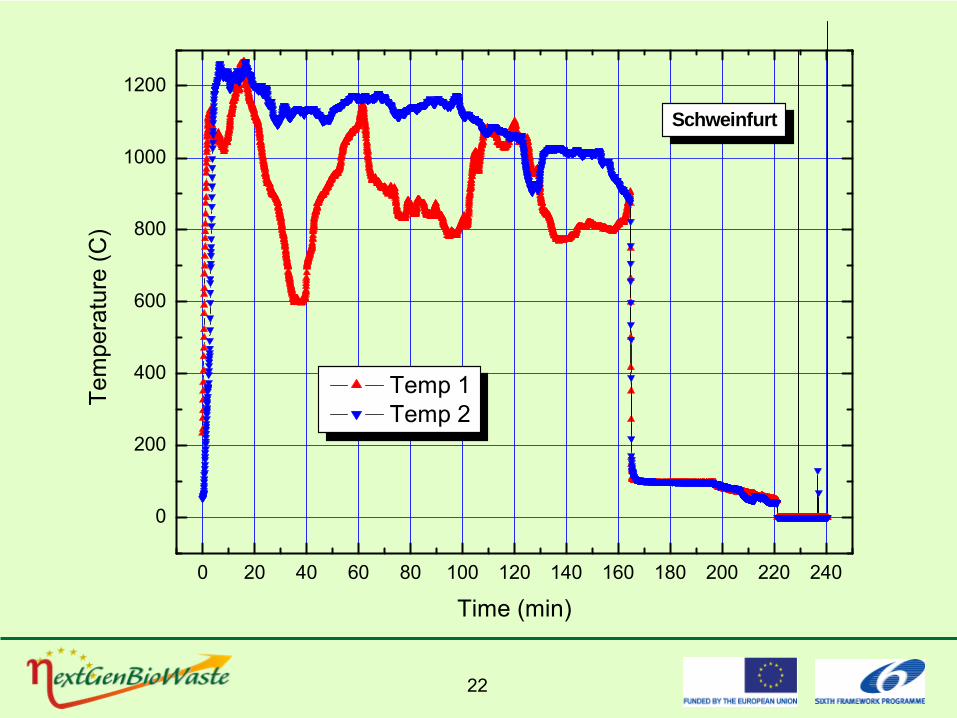
22
0 20 40 60 80 100 120 140 160 180 200 220 240
0
200
400
600
800
1000
1200
Schweinfurt
Tem
pera
ture
(C)
Time (min)
Temp 1 Temp 2
23
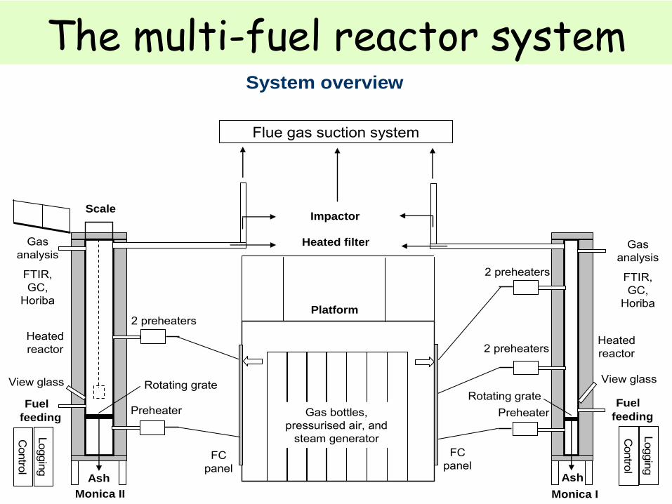
The multi-fuel reactor systemSystem overview
Impactor
Heated filter
Monica II Monica I
Platform
Scale
Gas bottles, pressurised air, and
steam generator
Fuel Fuel
Flue gas suction system
Gas analysis
FTIR, GC,
Horiba
2 preheaters
2 preheaters
Preheater
2 preheaters
Preheater
FC panel
FC panel
Control
Logging
Control
Logging
Gas analysis
FTIR, GC,
Horiba
Ash Ash
Heated reactor
Heated reactor
Rotating grateRotating grate
Key data:up to 1100 °CID: 195 mm, H: 2 m35 + 8 + 2*4.5 = 52 kW up to 1.2 kg fuel/hup to 260 Nl air/min
Key data:up to 1300 °CID: 100 mm, H: 2 m16 + 4 + 4*3 = 32 kWup to 0.5 kg fuel/hup to 120 Nl air/min
View glass View glass
feeding feeding
24
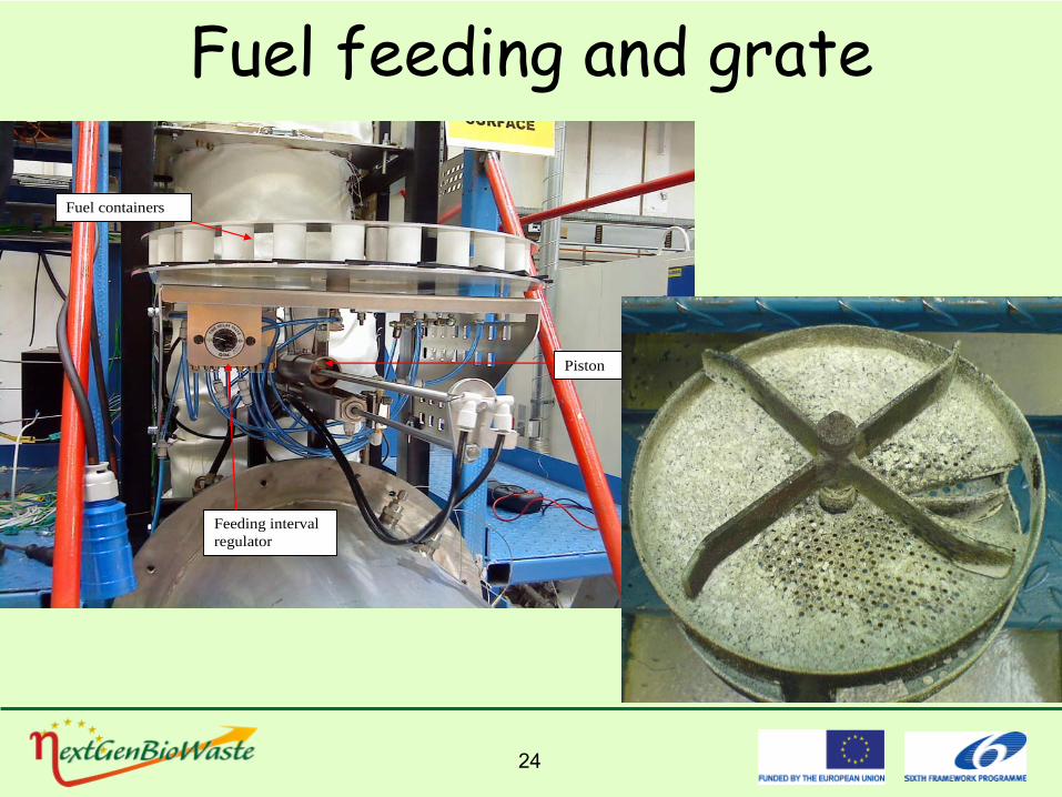
Fuel feeding and grate
Piston
Feeding interval regulator
Fuel containers
25
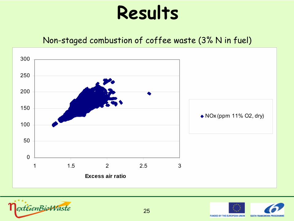
Results
0
50
100
150
200
250
300
1 1.5 2 2.5 3
Excess air ratio
NOx (ppm 11% O2, dry)
Non-staged combustion of coffee waste (3% N in fuel)
26
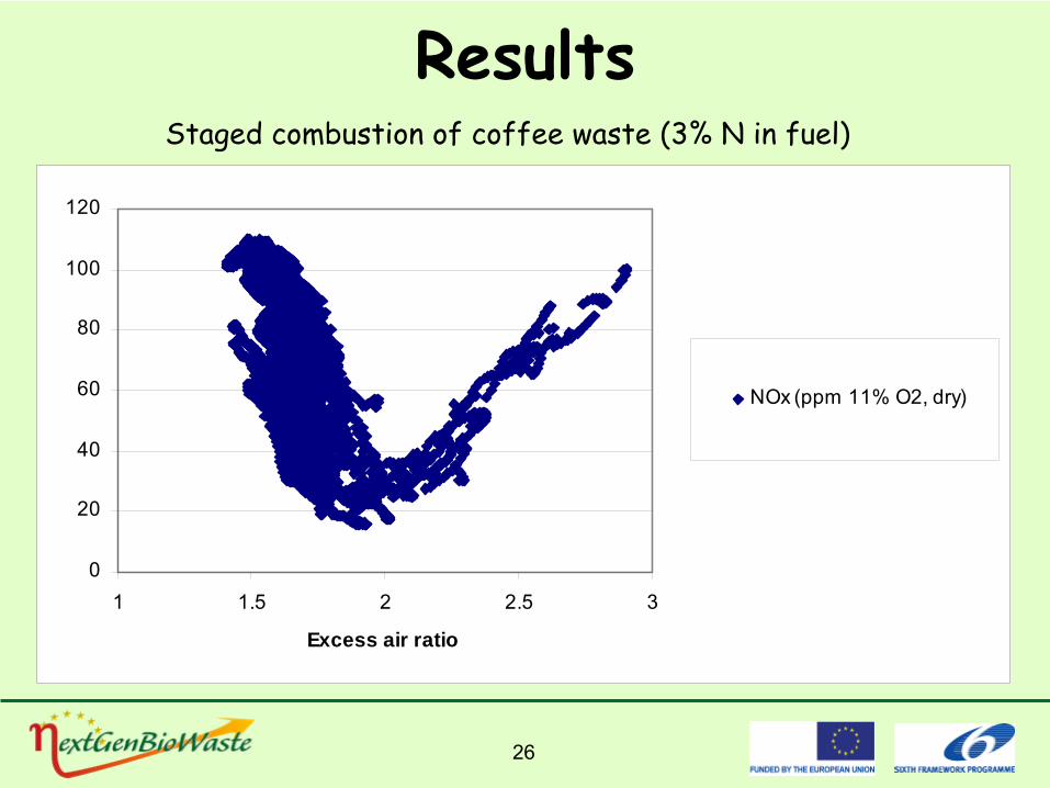
ResultsStaged combustion of coffee waste (3% N in fuel)
0
20
40
60
80
100
120
1 1.5 2 2.5 3
Excess air ratio
NOx (ppm 11% O2, dry)
27
New technology
and systematic slowness
•
Climate
researchers: We must!•
Technologist: We can!
•
Politicians: We shall!
•
So why
is renewable
energy
not being
implemented
to a greater
extent?
28
New technology
and systematic slowness
•
New technology
and innovations
must to a certain
extent
match existing
systems and future
plans•
Assumes
knowledge
and technology
at different
places
in the
value
chain•
The
challenge
is not only
to develop
new
technology, but
also
to develop the
society
in a direction
of
demaning
it
29
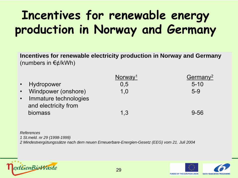
Incentives
for renewable
energy production
in Norway
and Germany
Incentives for renewable electricity production in Norway and Germany(numbers in €¢/kWh)
Norway1 Germany2
•
Hydropower
0,5 5-10•
Windpower
(onshore) 1,0 5-9
•
Immature technologiesand electricity
from
biomass 1,3 9-56
References1 St.meld. nr 29 (1998-1999)2 Mindestvergütungssätze nach dem neuen Erneuerbare-Energien-Gesetz (EEG) vom 21. Juli 2004
30
Non-technical barriers
•
Statement
from the NextGenBioWaste
project
”The
technologydemonstrated
is ripe for
evolution
of
the
legislationand framework”
31
What’s next?Raising
the
electrical
efficiency
even further
-
Trough
advanced combustion
-Through
gasification systems
Reduced
CO2
emissions- Combined
biopower/CHP and CCS-
The
only
possibility
for negative CO2
emissions!