Embed Size (px)
Citation preview
Towards All-digital mmWave Massive MIMO:Designing around Nonlinearities
Mohammed Abdelghany, Ali A. Farid, Upamanyu Madhow, Fellow, IEEE, and Mark J. W. Rodwell, Fellow, IEEE.
Abstract— The small carrier wavelengths at mmWave frequen-cies enable a large number of antenna elements to be packed intoa relatively small form factor. While existing implementationsemploy RF beamforming, it is now becoming possible to realizefully digital beamforming, with each antenna interfaced to aseparate RF chain. This opens up the possibility of supportingmultiuser MIMO, with the number of simultaneous users scaleslinearly with the number of antenna elements.
In this paper, we investigate the impact of two fundamentalhardware challenges in supporting such a fully digital architec-ture: the large bandwidth limits the available precision of analog-to-digital conversion, and the massive number of RF chains atmmWave frequencies constrains area and power consumption,which motivates relaxing the specifications on RF nonlinearitiessuch as the IIP3. We provide guidelines on ADC precisionand RF specifications for a multiuser MIMO uplink using alinear MMSE receiver, with nominal parameters correspondingto outdoor picocells operating at a data rate of 10 Gbps per user,and a carrier frequency of 140 GHz. Specifically, in nonlinearity-limited scenarios, we show that the output SNR of a user isproportional directly to the intrinsic SNR due to the nonlinearityself-noise and inversely to the system load factor.
Keywords—All-digital massive MIMO Uplink design, LoS chan-nel, Nonlinearity (IIP3), low-precision ADC, Load Factor, LMMSE.
I. INTRODUCTION
Advances in silicon-based Radio Frequency Integrated Cir-cuits (RFICs) are expected to enable next-generation com-munication systems to exploit the vast amounts of spectrumin the millimeter wave (mmWave) bands. The small carrierwavelengths enable the implementation of antenna arrays witha large number of elements in compact form factors. In thispaper, we consider a mmWave massive MIMO uplink systemdesign using a carrier frequency of 140 GHz for small cellapplications, supporting a large number of users at data ratesof 10 Gbps per user, targeting ranges of up to 100 m. Whileearly prototypes for mmWave transceivers in the 28 and 60GHz bands employ RF or hybrid beamforming, advances insilicon will soon enable the number of RF chains to scalewith the number of antennas, hence we explore an all-digitalarchitecture, similar to those that have become the norm forexisting systems at lower carrier frequencies.
M. Abdelghany A. Farid, U. Madhow, and M. Rodwell are with the Depart-ment of Electrical and Computer Engineering, University of California at SantaBarbara, Santa Barbara, CA 93106 USA (e-mail: [email protected];[email protected]; [email protected]; [email protected]).
A. Massive MIMO Uplink
We consider a massive MIMO uplink with LoS channelsbetween mobiles and base station. Let M denotes the numberof simultaneous users and N denotes the number of basestation antennas with β = M
N termed the load factor. Ourrunning example is for N = 256 base station antennas and βranging from 1
16 to 12 (i.e., M ranging from 16 to 128). To
see the potential of such a system, suppose that the bandwidthis 5 GHz and that each user employs QPSK modulation (withhigh-rate channel coding). Ignoring channel coding overhead,the data rate per user is 10 Gbps, and the aggregate throughputranges from 0.16 to 1.28 Tbps!
We note that the link budget for such a system is realizablewith low-cost silicon:• antenna element gain covering a hemisphere is 3 dBi,• 16-element array at the mobile gives 12 dB transmit
beamforming gain, plus 12 dB power pooling gain,• 256-element array in the base station gives 24 dB receive
beamforming gain,• noise figure for each RF chain in the base station of 7
dB,• the thermal noise of 5GHz BW is about -77 dBm,• and the free space path loss of an edge user at 100 m
using a carrier frequency of 140 GHz is about 115 dB.The transmit power required from each Power Amplifier (PA)at the mobile to achieve a target SNRedge can now becomputed as PPA = SNRedge|dB − 9 dBm. For example,SNRedge of about 16 dB (shown later to suffice for oursystem design) requires 7 dBm PA output, which is realizablein CMOS (CMOS designs of up to 11 dBm have been reportedin [1]).
B. Contributions
In this paper, we investigate two potential bottlenecks inrealizing this vision: Analog-to-Digital Converters (ADCs) forsuch high bandwidths and linear RF front ends at such highcarrier frequencies, are both costly (in terms of chip area) andpower-hungry. We would like, therefore, to design with thesmallest number of bits of ADC precision and the highest levelof RF nonlinearity (in terms of IIP3) possible; both of whichboil down to the question of how much overall nonlinearitywe can get away with. In this paper, we provide an analyticalframework that provides quantitative design prescriptions re-garding these. Specifically, the level of tolerable nonlinearitydepends on the load factor β. For example, 2-3 bits of ADCprecision and an IIP3 of 9 dB suffice for β = 1
16 , while β = 12
requires 4-5 bits of ADC precision and an IIP3 of 16 dB.
Our technical approach begins with the observation that,even for a moderate number of simultaneous users, the inputto each antenna is well modeled as a zero-mean complexGaussian random variable. This, together with a Bussgangdecomposition for the ADC and RF nonlinearities, allows us toderive a matched filter bound on the performance of a genericuser, which captures the effect of self-noise generated by thenonlinearity. This is then put together with a pessimistic esti-mate of the noise enhancement due to linear MMSE reception(the strategy assumed here) to provide an estimate of the SINR(signal-to-interference-plus-noise ratio). Specializing this to anedge user then yields the design prescriptions required tooperate at low outage probability.
C. Related WorkThere is a growing body of recent work on the spectral
efficiency for quantized massive MIMO. The work of [2]–[5]used a Bussgang approximation to model the DAC and ADC.In [2], the authors derived a lower bound on the achievable rateof M N quantized MIMO system. The authors of [3] derivedthe asymptotic achievable rate for the downlink channel in thepresence of ADC and DAC. They discovered that increasingthe load factor by four times requires one more bit of the ADCand DAC. In [4], the authors proposed a channel estimationalgorithm and an approximation for the achievable rate ofthe quantized uplink massive MIMO system. Authors of [5]proposed a channel estimation algorithm for a channel selectivequantized uplink massive MIMO system that deploys OFDM.In [6], They compared digital and hybrid RF beamformingarchitectures for the downlink and showed that the All-digitalarchitecture is the most area and power efficient. A detailedhardware model was used in [7] for downlink modeling.
While our analytical approach leverages Bussgang approx-imations for nonlinearities as in prior work [2]–[5], we areable to provide compact design prescriptions by combiningthe matched filter bound with estimated noise enhancement,together with averaging over the spatial distribution of users.
II. SYSTEM MODEL
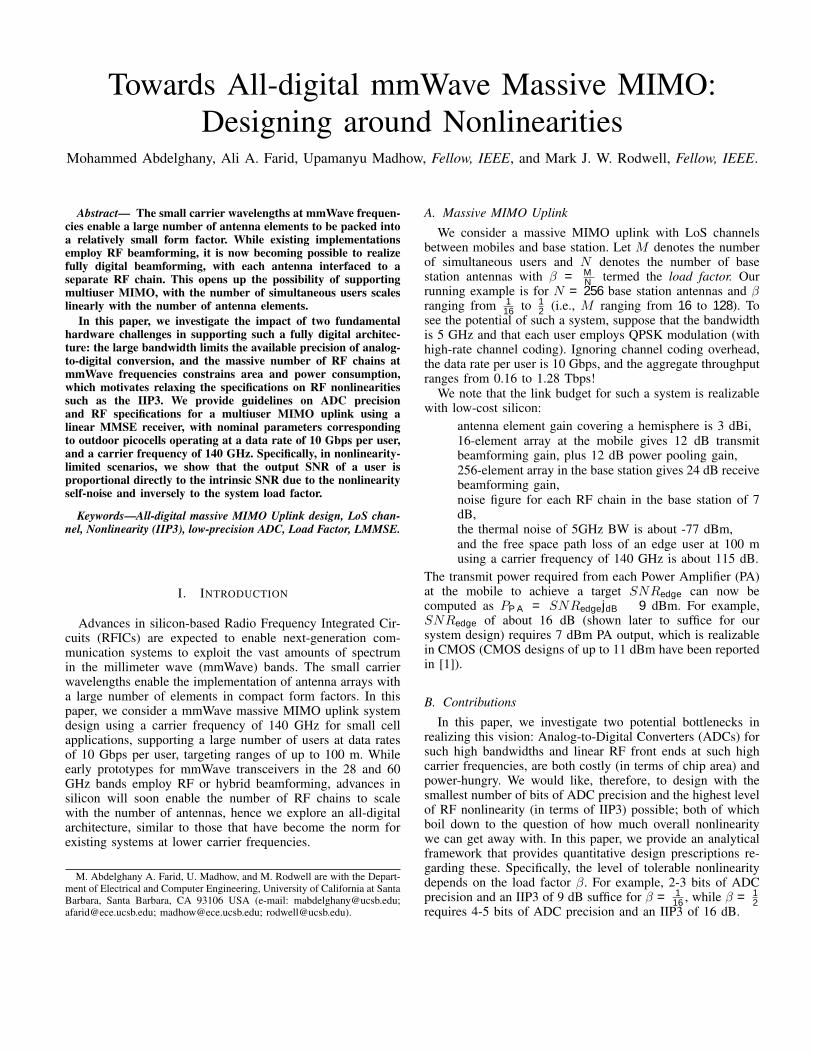
Fig. 1 shows the system model. The base station performshorizontal scanning with a 1D half-wavelength spaced N -element array. Fig. 1 shows the antenna array and the coordi-nate system. We constrain the field of view to 2 +
2 , and choose such that no grating lobe appearsin the array radiation pattern. Each mobile is assumed to beable to perform ideal transmit beamforming towards the basestation.
The mobiles are uniformly distributed inside a region bor-dered by a minimum and a maximum distance away fromthe base station, Rmin and Rmax, respectively. A spatial fre-quency m = 2 dx sin m defines the angular location of
the mth mobile. While the mobiles are placed randomly inour simulations, we enforce a minimum separation in spatialfrequency between any two mobiles in order not to incurexcessive interference, arbitrarily choosing it as half the 3dBbeamwidth: min = 2 783
N [8]. For example, The systemcould schedule such mobiles in different time slots. Fig. 2
Figure 1: The figure illustrates the studied system model. Thecell size is constrained radially between Rmin and Rmax andangularly between 2 + 2 . UE andBW3dB stand for the user equipment and the 3 dB beamwidth,respectively. We model the RF nonlinearity by a saturated thirdorder polynomial model and use an overloaded uniform ADCwith k-bit per dimension. A linear MMSE receiver is used afterthe ADCs.
illustrates an instantiation of the mobiles distribution overthe cell area and the interference between two users if aspatial matched filter is used. We assume a Line-of-Sight (LoS)channel between the base station and the mobiles with noshadowing nor fading. The channel vector for the mth mobilecan be written as follows:
hm = Am [1 ej m ej2 m ej(N 1) m ] (1)
where A2m = 4 Rm
2
depends on the radial location Rm of
mobile m, using the Friis formula for path loss. In the remain-der of this section, we describe the nonlinearities modeled inour design. The LMMSE receiver used in the digital backendaccounts for the self-noise coming from these nonlinearities(characterized in the next section), as well as the thermal noise.
A. RF Nonlinearity ModelWe have reduced all amplification stages in an RF chain into
one nonlinearity stage with unity gain. We model the amplitudenonlinearity distortion using a saturated third-order polynomialfunction, as follows,
y(t) =x(t)(1 4 x(t) 2
3 IIP3) if x(t) 2 IIP3
4x(t)
3 x(t) IIP3 if x(t) 2 > IIP3
4
(2)
We use the third-order Input Intercept Point (IIP3) to describethe coefficient of the third order term. IIP3 is an important de-sign parameter for RF designers [9]. In the above formulationand without loss of generality, we assume that the averagepower of the input signal E( x(t) 2) = 0 dBm. Thus, weadjust the power of the input signal to be 0 dBm before itgoes through the nonlinearity. Hence, the IIP3 used is called

030
60
90
120
150180
-150
-120
-90
-60
-30
0 20 40 60 80 100R
(a)
-0.05 -0.025 0 0.025 0.05 (Rad)
0
0.2
0.4
0.6
0.8
1
3 dB
(b)
Figure 2: Fig. (a) depicts an instantiation of 128 mobiles ona polar chart of cell constrained by Rmin = 5m and Rmax =100m radially, and −π/2 + π/20 ≤ θ ≤ π/2− π/20. Fig. (b)shows the kernel of the cross-correlation of the channels oftwo adjacent users with a spatial frequency difference of ∆Ω,where hi = hi/
√N . Note that the closest two users, whose
relative spatial frequencies are depicted by the red points, areseparated by larger or equal to half the 3dB Beamwidth.
normalized IIP3 and is specified in dB. In this work, weconsider the nonlinearity to be memoryless and free of phasedistortion. Fig. 3 (a) illustrates examples of the nonlinearitymodel I/O characteristics.
B. ADC ModelWe employ an overloaded uniform ADC [10]. It comprises
two regions in its I/O characteristic, the granular and overloadregions. The granular region is quantized uniformly; hencethe quantization noise is bounded. On the other hand, onequantization level represents the overload region, so that theerror is unbounded. Similar to the RF nonlinearity, we adjustthe power of the incoming signal to be 0 dBm per dimensionand design the quantizer based on that. Fig. 3 (b) depicts anexample of an overloaded uniform quantizer for a standardGaussian signal.
III. ANALYTICAL FRAMEWORK
We first perform a Bussgang linearization for the receivedsignal at each antenna element, from which we can develop amatched filter bound for the output SNR when consideringonly the self-noise induced by the nonlinearity. We theninclude the impact of thermal noise into the matched filterbound. Subsequently, we derive a lower bound for the LMMSEoutput SINR by using the noise enhancement for an idealsystem (with no nonlinearity) as an upper bound for that inour system.
A. Bussgang linearizationFor a zero mean complex random variable Z and a non-
linearity g(·), we can compute the best linear fit aZ (in theMMSE sense) using the orthogonality principle:
E[(g(Z)− aZ)Z∗] = 0,
-30 -20 -10 0 10Pin (dBm)
0
0.02
0.04
0.06
0.08
0.1
p(P in
)
-40
-30
-20
-10
0
10
20
P out (d
Bm
)
IIP3/Pin=12dBm
IIP3/Pin=16dBmIIP3/Pin=20dBm
p(Pin)
(a)
-3 -2 -1 0 1 2 3x
0.05
0.1
0.15
0.2
0.25
0.3
0.35
0.4
0.45
p(x)
Granular RegionOverload
RegionOverload
Region
(b)
Figure 3: This work studies the nonlinearity and quantizationeffect on the performance of a massive MIMO uplink system.Fig. (a) illustrates curves of different nonlinearity models char-acterized by their IIP3. It also shows the histogram of the com-plex envelope amplitude for a normalized-to-0dBm passbandsignal. Fig. (b) Illustrates the histogram of the real/imaginaryparts of the normalized-to-0dBm baseband signal along withADC quantization bins. The ADC I/O characteristic comprisesthe Granular and Overload regions. Highly probable smallquantization errors characterize the granular region. On theother hand, low-probability large clipping errors characterizethe overload region.
so thata =
E[g(Z)Z∗]
E[|Z|2], (3)
with the variance of the approximation error is given by
σ2NL = E[|g(Z)|2]− |E[g(Z)Z∗]|2
E[|Z|2]. (4)
We can explicitly compute a and σ2NL for any distribution
for Z. In our case, we wish to apply this to the receivedsignal at each antenna, which, by virtue of the central limittheorem, is well modeled as zero-mean complex Gaussian evenfor a moderate number of mobiles. We, therefore, compute theBussgang linearization a and σ2
NL for a normalized setting,Z ∼ CN(0, 1), and then scale it appropriately.
Let us now define the intrinsic SNR of the nonlinearity g as
SNR(g) =a2
σ2NL
. (5)
Approximating the received signals at different antenna ele-ments as jointly Gaussian, we can use Bussgang’s originalresult [11] to infer that the error terms across the antennasare uncorrelated. We now discuss how this model can be usedto get an optimistic estimate, or matched filter bound, for anygiven user in a multiuser MIMO system (with a large enoughnumber of users that the preceding Gaussian model for theincoming signal at each antenna holds).
B. Matched filter bound for self-noise from nonlinearitySuppose that Am,m = 1, . . . ,M are the amplitudes
of the incoming waves for the M users. We can therefore

model the incoming signal at each receive antenna as Z ∼CN(0,
∑Mm=1A
2m). Our prior analysis of nonlinearity g goes
through if we scale the incoming signal to unit variance asfollows,
Z =Z
s,
where the scale factor s is given by
s2 = MA2rms, (6)
and
Arms =
√√√√ 1
M
M∑m=1
A2m (7)
is the root mean square (rms) amplitude, averaged across users.We, therefore, have g(Z) = aZ + e as a per-antenna model
for the normalized received signal. Now, when we correlateagainst the spatial matched filter for the mth user across theN antennas, and ignore the interference from other users, weobtain the output
ym = aNAm/s+ n,
where σ2n = Nσ2
NL.Thus, the output SNR of the matched filter for the mth user
is given by
SNRmf(g)m =
a2N2A2m/s
2
Nσ2NL
= SNR(g)A2m
βA2rms
, (8)
where β = MN is the load factor. It is clear, therefore, that
performance depends on the intrinsic SNR of the nonlinearity,the load factor, and the ratio of the strength of the given usercompared to the average user strength.
We are interested in supporting users at the cell edge. hencewe now set Am to the worst-case amplitude Amin, whilecomputing Arms by a statistical average
√E[A2] given the
users distribution, assuming a large enough number of users.For example, for users who are uniformly distributed over thearea bounded by [Rmin, Rmax] and a given angular range, weobtain upon straightforward computation that:
A2min
A2rms
=1− R2
min
R2max
2 log RmaxRmin
.
This yields that
SNRmf(g)edge = SNR(g)
1
β
1− R2min
R2max
2 log RmaxRmin
.
C. Matched filter bound with thermal noiseSuppose that σ2
th is the variance of the complex Gaussianthermal noise at each antenna. Summing up the variance of theself-noise and the thermal noise at the matched filter output,it can be shown that
SNRmf(g+σ2
th)edge =
11
SNRmf(g)edge
+ 1+SNR(g)SNR(g)
1
SNRmf(σ2th)
edge
, (9)
8 9 10 11 12 13 14SNRedge
10-4
10-3
10-2
10-1
=1/16=1/8=1/4=1/3=1/2
(a)
1/16 1/8 1/4 1/2Load Factor ( )
9
10
11
12
13
SNR
edge
Multi UsersSingle User
(b)
Figure 4: Fig. (a) shows the BER that 95% of the UEs havebetter than in an ideal system, i.e., no ADC or nonlinearities,for different load factors. Fig (b) collects the SNRs of the edgeuser, i.e., at 100 m away from the base station, that guaranteethat 95% of the mobiles have raw BER of 10−3 for differentload factors. We use the gap in SNR between the multiusercase and single-user case in Fig. (b) to account for interferenceand noise enhancement when we drive a lower bound on theLMMSE output SINR.
where
SNRmf(σ2
th)edge =
NA2min
σ2th
.
D. Lower bound on LMMSE output SINRThe effective noise variance is increased by the self-noise
due to the nonlinearity, for a given user configuration. One canthen show that while the output SINR for each user is larger inthe ideal system, the ratio of the SNR to output SINR (or theirdifference in dB) is also larger in the ideal system. That is, thenoise enhancement in the ideal system, which we denote bySINRGapIdeal, is an upper bound on that for the actual system.
We compute this noise enhancement bound numerically byevaluating SINRGapIdeal through simulations, as shown in Fig.4, where SNRedge =
NA2100m
σ2th
, and A100m is the receivedamplitude of the user at 100 m.
If we interpret LMMSE reception in the ideal system atthe relatively large SNRs considered here as being close tozero-forcing reception, an intuitive approximation for the noiseenhancement is given by
SINRGapIdeal ≈ 1− M − 1
N.
We find that this approximation is quite accurate in the regimeconsidered here, but we do not at present have an analyticalcharacterization.
IV. NUMERICAL RESULTS
The system parameters are as described in Sections I and II,and power control is not employed. We measure link qualityby the outage probability at a target uncoded BER of 10−3
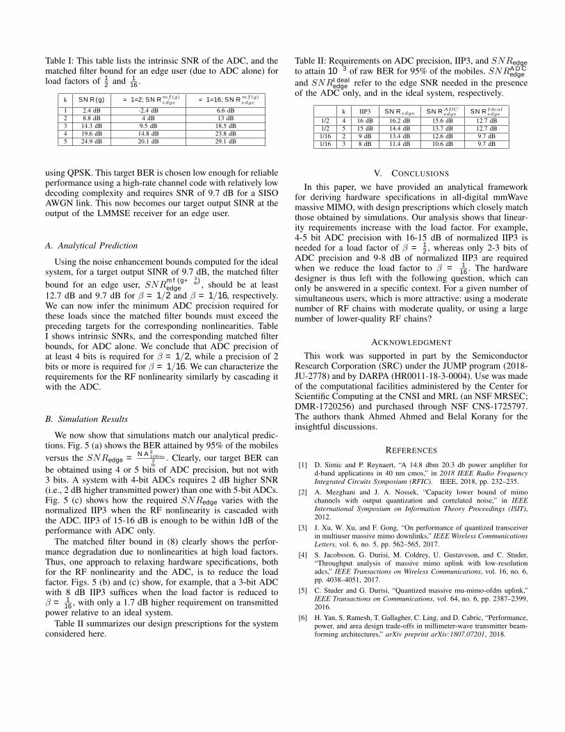
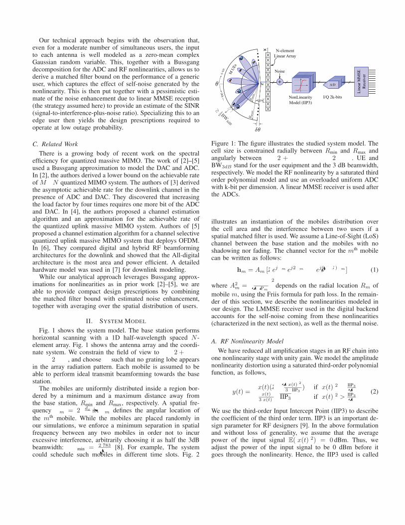
Table I: This table lists the intrinsic SNR of the ADC, and thematched filter bound for an edge user (due to ADC alone) forload factors of 1
2 and 116 .
k SNR(g) β = 1/2, SNRmf(g)edge β = 1/16, SNR
mf(g)edge
1 2.4 dB -2.4 dB 6.6 dB2 8.8 dB 4 dB 13 dB3 14.3 dB 9.5 dB 18.5 dB4 19.6 dB 14.8 dB 23.8 dB5 24.9 dB 20.1 dB 29.1 dB
using QPSK. This target BER is chosen low enough for reliableperformance using a high-rate channel code with relatively lowdecoding complexity and requires SNR of 9.7 dB for a SISOAWGN link. This now becomes our target output SINR at theoutput of the LMMSE receiver for an edge user.
A. Analytical Prediction
Using the noise enhancement bounds computed for the idealsystem, for a target output SINR of 9.7 dB, the matched filterbound for an edge user, SNRmf(g+σ2
th)edge , should be at least
12.7 dB and 9.7 dB for β = 1/2 and β = 1/16, respectively.We can now infer the minimum ADC precision required forthese loads since the matched filter bounds must exceed thepreceding targets for the corresponding nonlinearities. TableI shows intrinsic SNRs, and the corresponding matched filterbounds, for ADC alone. We conclude that ADC precision ofat least 4 bits is required for β = 1/2, while a precision of 2bits or more is required for β = 1/16. We can characterize therequirements for the RF nonlinearity similarly by cascading itwith the ADC.
B. Simulation Results
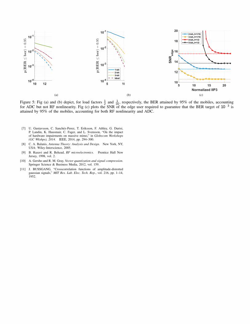
We now show that simulations match our analytical predic-tions. Fig. 5 (a) shows the BER attained by 95% of the mobilesversus the SNRedge =
NA2100m
σ2th
. Clearly, our target BER canbe obtained using 4 or 5 bits of ADC precision, but not with3 bits. A system with 4-bit ADCs requires 2 dB higher SNR(i.e., 2 dB higher transmitted power) than one with 5-bit ADCs.Fig. 5 (c) shows how the required SNRedge varies with thenormalized IIP3 when the RF nonlinearity is cascaded withthe ADC. IIP3 of 15-16 dB is enough to be within 1dB of theperformance with ADC only.
The matched filter bound in (8) clearly shows the perfor-mance degradation due to nonlinearities at high load factors.Thus, one approach to relaxing hardware specifications, bothfor the RF nonlinearity and the ADC, is to reduce the loadfactor. Figs. 5 (b) and (c) show, for example, that a 3-bit ADCwith 8 dB IIP3 suffices when the load factor is reduced toβ = 1
16 , with only a 1.7 dB higher requirement on transmittedpower relative to an ideal system.
Table II summarizes our design prescriptions for the systemconsidered here.
Table II: Requirements on ADC precision, IIP3, and SNRedgeto attain 10−3 of raw BER for 95% of the mobiles. SNRADCedge
and SNRIdealedge refer to the edge SNR needed in the presenceof the ADC only, and in the ideal system, respectively.
β k IIP3 SNRedge SNRADCedge SNRIdealedge
1/2 4 16 dB 16.2 dB 15.6 dB 12.7 dB1/2 5 15 dB 14.4 dB 13.7 dB 12.7 dB1/16 2 9 dB 13.4 dB 12.6 dB 9.7 dB1/16 3 8 dB 11.4 dB 10.6 dB 9.7 dB
V. CONCLUSIONS
In this paper, we have provided an analytical frameworkfor deriving hardware specifications in all-digital mmWavemassive MIMO, with design prescriptions which closely matchthose obtained by simulations. Our analysis shows that linear-ity requirements increase with the load factor. For example,4-5 bit ADC precision with 16-15 dB of normalized IIP3 isneeded for a load factor of β = 1
2 , whereas only 2-3 bits ofADC precision and 9-8 dB of normalized IIP3 are requiredwhen we reduce the load factor to β = 1
16 . The hardwaredesigner is thus left with the following question, which canonly be answered in a specific context. For a given number ofsimultaneous users, which is more attractive: using a moderatenumber of RF chains with moderate quality, or using a largenumber of lower-quality RF chains?
ACKNOWLEDGMENT
This work was supported in part by the SemiconductorResearch Corporation (SRC) under the JUMP program (2018-JU-2778) and by DARPA (HR0011-18-3-0004). Use was madeof the computational facilities administered by the Center forScientific Computing at the CNSI and MRL (an NSF MRSEC;DMR-1720256) and purchased through NSF CNS-1725797.The authors thank Ahmed Ahmed and Belal Korany for theinsightful discussions.
REFERENCES
[1] D. Simic and P. Reynaert, “A 14.8 dbm 20.3 db power amplifier ford-band applications in 40 nm cmos,” in 2018 IEEE Radio FrequencyIntegrated Circuits Symposium (RFIC). IEEE, 2018, pp. 232–235.
[2] A. Mezghani and J. A. Nossek, “Capacity lower bound of mimochannels with output quantization and correlated noise,” in IEEEInternational Symposium on Information Theory Proceedings (ISIT),2012.
[3] J. Xu, W. Xu, and F. Gong, “On performance of quantized transceiverin multiuser massive mimo downlinks,” IEEE Wireless CommunicationsLetters, vol. 6, no. 5, pp. 562–565, 2017.
[4] S. Jacobsson, G. Durisi, M. Coldrey, U. Gustavsson, and C. Studer,“Throughput analysis of massive mimo uplink with low-resolutionadcs,” IEEE Transactions on Wireless Communications, vol. 16, no. 6,pp. 4038–4051, 2017.
[5] C. Studer and G. Durisi, “Quantized massive mu-mimo-ofdm uplink,”IEEE Transactions on Communications, vol. 64, no. 6, pp. 2387–2399,2016.
[6] H. Yan, S. Ramesh, T. Gallagher, C. Ling, and D. Cabric, “Performance,power, and area design trade-offs in millimeter-wave transmitter beam-forming architectures,” arXiv preprint arXiv:1807.07201, 2018.
10 12 14 16 18 20SNRedge
10-4
10-3
10-2
10-13-bit4-bit5-bitIdeal
(a)
5 10 15 20SNRedge
10-4
10-3
10-2
10-1
1-bit2-bit3-bitIdeal
(b)
5 10 15 20Normalized IIP3
10
12
14
16
18
20
SNR
edge
2-bit, =1/163-bit, =1/164-bit, =1/25-bit, =1/2
(c)
Figure 5: Fig (a) and (b) depict, for load factors 12 and 1
16 , respectively, the BER attained by 95% of the mobiles, accountingfor ADC but not RF nonlinearity. Fig (c) plots the SNR of the edge user required to guarantee that the BER target of 10−3 isattained by 95% of the mobiles, accounting for both RF nonlinearity and ADC.
[7] U. Gustavsson, C. Sanchez-Perez, T. Eriksson, F. Athley, G. Durisi,P. Landin, K. Hausmair, C. Fager, and L. Svensson, “On the impactof hardware impairments on massive mimo,” in Globecom Workshops(GC Wkshps), 2014. IEEE, 2014, pp. 294–300.
[8] C. A. Balanis, Antenna Theory: Analysis and Design. New York, NY,USA: Wiley-Interscience, 2005.
[9] B. Razavi and R. Behzad, RF microelectronics. Prentice Hall NewJersey, 1998, vol. 2.
[10] A. Gersho and R. M. Gray, Vector quantization and signal compression.Springer Science & Business Media, 2012, vol. 159.
[11] J. BUSSGANG, “Crosscorrelation functions of amplitude-distortedgaussian signals,” MIT Res. Lab. Elec. Tech. Rep., vol. 216, pp. 1–14,1952.