Embed Size (px)
Citation preview
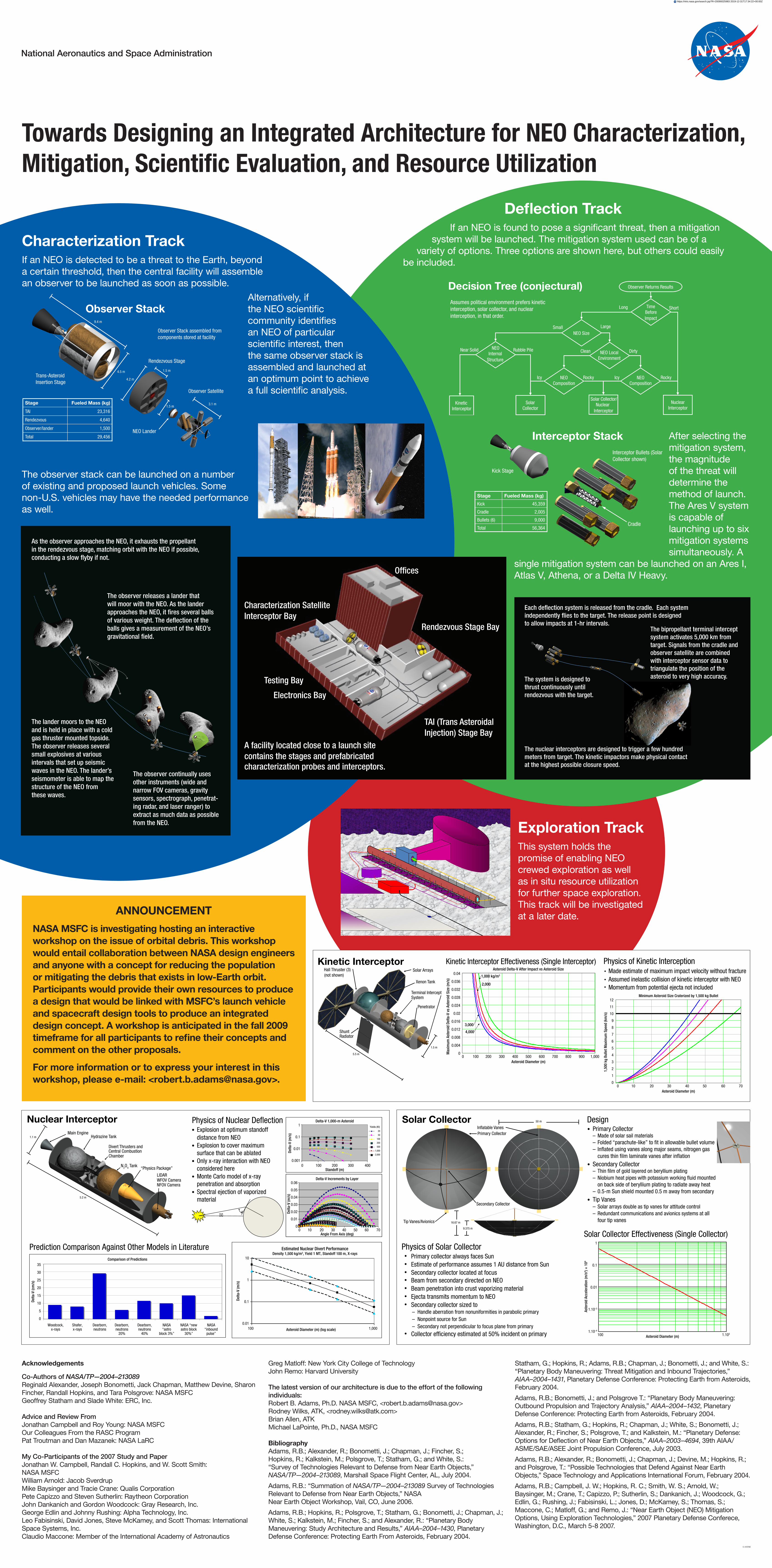
Towards Designing an Integrated Architecture for NEO Characterization, Mitigation, Scientific Evaluation, and Resource Utilization
Decision Tree (conjectural) Observer Returns Results
NEO Size
Assumes political environment prefers kinetic interception, solar collector, and nuclear interception, in that order.
NEO Internal
Structure
NEO Composition
NEO Local Environment
Kinetic Interceptor
Solar Collector
Small Large
Dirty Clean Near Solid Rubble Pile
Rocky Icy
Time Before Impact
Short Long
Nuclear Interceptor
Solar Collector/ Nuclear
Interceptor
NEO Composition
Rocky Icy
Interceptor Stack
Kick Stage
Cradle
Interceptor Bullets (Solar Collector shown)
Stage Fueled Mass (kg)
Kick 45,359
Cradle 2,005
Bullets (6) 9,000
Total 56,364
Acknowledgements
Co-Authors of NASA/TP—2004–213089Reginald Alexander, Joseph Bonometti, Jack Chapman, Matthew Devine, Sharon Fincher, Randall Hopkins, and Tara Polsgrove: NASA MSFCGeoffrey Statham and Slade White: ERC, Inc.
Advice and Review FromJonathan Campbell and Roy Young: NASA MSFCOur Colleagues From the RASC ProgramPat Troutman and Dan Mazanek: NASA LaRC
My Co-Participants of the 2007 Study and PaperJonathan W. Campbell, Randall C. Hopkins, and W. Scott Smith: NASA MSFCWilliam Arnold: Jacob SverdrupMike Baysinger and Tracie Crane: Qualis CorporationPete Capizzo and Steven Sutherlin: Raytheon CorporationJohn Dankanich and Gordon Woodcock: Gray Research, Inc.George Edlin and Johnny Rushing: Alpha Technology, Inc.Leo Fabisinski, David Jones, Steve McKamey, and Scott Thomas: International Space Systems, Inc.Claudio Maccone: Member of the International Academy of Astronautics
Greg Matloff: New York City College of TechnologyJohn Remo: Harvard University
The latest version of our architecture is due to the effort of the following individuals:Robert B. Adams, Ph.D. NASA MSFC, <[email protected]>Rodney Wilks, ATK, <[email protected]>Brian Allen, ATKMichael LaPointe, Ph.D., NASA MSFC
BibliographyAdams, R.B.; Alexander, R.; Bonometti, J.; Chapman, J.; Fincher, S.; Hopkins, R.; Kalkstein, M.; Polsgrove, T.; Statham, G.; and White, S.: “Survey of Technologies Relevant to Defense from Near Earth Objects,” NASA/TP—2004–213089, Marshall Space Flight Center, AL, July 2004.
Adams, R.B.: “Summation of NASA/TP—2004–213089 Survey of Technologies Relevant to Defense from Near Earth Objects,” NASA Near Earth Object Workshop, Vail, CO, June 2006.
Adams, R.B.; Hopkins, R.; Polsgrove, T.; Statham, G.; Bonometti, J.; Chapman, J.; White, S.; Kalkstein, M.; Fincher, S.; and Alexander, R.: “Planetary Body Maneuvering: Study Architecture and Results,” AIAA–2004–1430, Planetary Defense Conference: Protecting Earth From Asteroids, February 2004.
Statham, G.; Hopkins, R.; Adams, R.B.; Chapman, J.; Bonometti, J.; and White, S.: “Planetary Body Maneuvering: Threat Mitigation and Inbound Trajectories,” AIAA–2004–1431, Planetary Defense Conference: Protecting Earth from Asteroids, February 2004.
Adams, R.B.; Bonometti, J.; and Polsgrove T.: “Planetary Body Maneuvering: Outbound Propulsion and Trajectory Analysis,” AIAA–2004–1432, Planetary Defense Conference: Protecting Earth from Asteroids, February 2004.
Adams, R.B.; Statham, G.; Hopkins, R.; Chapman, J.; White, S.; Bonometti, J.; Alexander, R.; Fincher, S.; Polsgrove, T.; and Kalkstein, M.: “Planetary Defense: Options for Deflection of Near Earth Objects,” AIAA–2003–4694, 39th AIAA/ASME/SAE/ASEE Joint Propulsion Conference, July 2003.
Adams, R.B.; Alexander, R.; Bonometti, J.; Chapman, J.; Devine, M.; Hopkins, R.; and Polsgrove, T.: “Possible Technologies that Defend Against Near Earth Objects,” Space Technology and Applications International Forum, February 2004.
Adams, R.B.; Campbell, J. W.; Hopkins, R. C.; Smith, W. S.; Arnold, W.; Baysinger, M.; Crane, T.; Capizzo, P.; Sutherlin, S.; Dankanich, J.; Woodcock, G.; Edlin, G.; Rushing, J.; Fabisinski, L.; Jones, D.; McKamey, S.; Thomas, S.; Maccone, C.; Matloff, G.; and Remo, J.: “Near Earth Object (NEO) Mitigation Options, Using Exploration Technologies,” 2007 Planetary Defense Conferece, Washington, D.C., March 5-8 2007.
National Aeronautics and Space Administration
Exploration Track This system holds the promise of enabling NEO crewed exploration as well as in situ resource utilization for further space exploration. This track will be investigated at a later date.ANNOUNCEMENT
NASA MSFC is investigating hosting an interactive workshop on the issue of orbital debris. This workshop would entail collaboration between NASA design engineers and anyone with a concept for reducing the population or mitigating the debris that exists in low-Earth orbit. Participants would provide their own resources to produce a design that would be linked with MSFC’s launch vehicle and spacecraft design tools to produce an integrated design concept. A workshop is anticipated in the fall 2009 timeframe for all participants to refine their concepts and comment on the other proposals.
For more information or to express your interest in this workshop, please e-mail: <[email protected]>.
Characterization TrackIf an NEO is detected to be a threat to the Earth, beyond a certain threshold, then the central facility will assemble an observer to be launched as soon as possible.
As the observer approaches the NEO, it exhausts the propellant in the rendezvous stage, matching orbit with the NEO if possible, conducting a slow �yby if not.
The observer releases a lander that will moor with the NEO. As the lander approaches the NEO, it �res several balls of various weight. The de�ection of the balls gives a measurement of the NEO’s gravitational �eld.
The lander moors to the NEO and is held in place with a cold gas thruster mounted topside. The observer releases several small explosives at various intervals that set up seismic waves in the NEO. The lander’s seismometer is able to map the structure of the NEO from these waves.
The observer continually uses other instruments (wide and narrow FOV cameras, gravity sensors, spectrograph, penetrat-ing radar, and laser ranger) to extract as much data as possible from the NEO.
Alternatively, if the NEO scientific community identifies an NEO of particular scientific interest, then the same observer stack is assembled and launched at an optimum point to achieve a full scientific analysis.
The system is designed to thrust continuously until rendezvous with the target.
The nuclear interceptors are designed to trigger a few hundred meters from target. The kinetic impactors make physical contact at the highest possible closure speed.
The bipropellant terminal intercept system activates 5,000 km from target. Signals from the cradle and observer satellite are combined with interceptor sensor data to triangulate the position of the asteroid to very high accuracy.
Each de�ection system is released from the cradle. Each system independently �ies to the target. The release point is designed to allow impacts at 1-hr intervals.
The observer stack can be launched on a number of existing and proposed launch vehicles. Some non-U.S. vehicles may have the needed performance as well.
Solar Collector Effectiveness (Single Collector)
Aste
roid
Acc
eler
atio
n (m
/s2 )
× 1
06
Asteroid Diameter (m)
1
0.1
0.01
1.10–3
1.10–4
100 1.103
Kinetic Interceptor Effectiveness (Single Interceptor)
1,000 kg/m3
2,000
3,000
4,000
Max
imum
Ast
eroi
d De
lta-V
vs
Aste
roid
Siz
e (m
/s)
Asteroid Delta-V After Impact vs Asteroid Size
Asteroid Diameter (m)
0.04
0.036
0.032
0.028
0.024
0.02
0.016
0.012
0.008
0.004
00 100 200 300 400 500 600 700 800 900 1,000
Physics of Kinetic Interception
1,50
0 kg
Bul
let M
axim
um S
peed
(km
/s)
Minimum Asteroid Size Craterized by 1,500 kg Bullet
Asteroid Diameter (m)
12
11
10
9
8
7
6
5
4
3
2
1
00 10 20 30 40 50 60 70
• Made estimate of maximum impact velocity without fracture • Assumed inelastic collision of kinetic interceptor with NEO • Momentum from potential ejecta not included
Trans-Asteroid Insertion Stage
Rendezvous Stage
Observer Satellite
Observer Stack
NEO Lander
Stage Fueled Mass (kg)
TAI 23,316
Rendezvous 4,640
Observer/lander 1,500
Total 29,456
9.4 m
1.5 m
3.1 m 1.5 m
4.5 m
4.2 m
Observer Stack assembled from components stored at facility
Physics of Solar Collector • Primary collector always faces Sun • Estimate of performance assumes 1 AU distance from Sun • Secondary collector located at focus • Beam from secondary directed on NEO • Beam penetration into crust vaporizing material • Ejecta transmits momentum to NEO • Secondary collector sized to
– Handle aberration from nonuniformities in parabolic primary – Nonpoint source for Sun – Secondary not perpendicular to focus plane from primary
• Collector ef�ciency estimated at 50% incident on primary
Design • Primary Collector – Made of solar sail materials – Folded “parachute-like” to �t in allowable bullet volume – In�ated using vanes along major seams, nitrogen gas cures thin �lm laminate vanes after in�ation
• Secondary Collector – Thin �lm of gold layered on beryllium plating – Niobium heat pipes with potassium working �uid mounted on back side of beryllium plating to radiate away heat – 0.5-m Sun shield mounted 0.5 m away from secondary
• Tip Vanes – Solar arrays double as tip vanes for attitude control – Redundant communications and avionics systems at all four tip vanes
“Physics Package”
LIDAR WFOV Camera NFOV Camera
Divert Thrusters and Central Combustion Chamber
N2O4 Tank
Hydrazine Tank Main Engine
5.2 m
1.1 m
Nuclear Interceptor Physics of Nuclear De�ection• Explosion at optimum standoff distance from NEO• Explosion to cover maximum surface that can be ablated• Only x-ray interaction with NEO considered here• Monte Carlo model of x-ray penetration and absorption• Spectral ejection of vaporized material
Standoff (m)
Angle From Axis (deg)
Delta-V 1,000-m Asteroid
Delta-V Increments by Layer
Delta
-V (m
/s)
Delta
-V (m
/s)
1
0.1
0.01
0.001
20
50
100
200
500
1,000
2,000
0.06
0.05
0.04
0.03
0.02
0.01
0
0 100 200 300 400
0 10 20 30 40 50 60 70
Yields (Kt)
50 m
In�atable Vanes Primary Collector
Secondary Collector
Tip Vanes/Avionics
Solar Collector
9.375 m
16.67 m
Asteroid Diameter (m) (log scale)
Estimated Nuclear Divert PerformanceDensity 1,500 kg/m3, Yield 1 MT, Standoff 100 m, X-rays
Delta
-V (m
/s)
10
1
0.1
0.01100 1,000
Prediction Comparison Against Other Models in Literature Comparison of Predictions
Delta
-V (c
m/s
)
35
30
25
20
15
10
5
0
Woodcock, Shafer, Dearborn, Dearborn, Dearborn, NASA NASA “new NASA x-rays x-rays neutrons neutrons neutrons “astro astro block “inbound 20% 40% block 3%” 30%” pulse”
Kinetic Interceptor Hall Thruster (3) (not shown)
Solar Arrays
Xenon Tank
Terminal Intercept System
Penetrator
Shunt Radiator
5.5 m
1.5 m
A facility located close to a launch site contains the stages and prefabricated characterization probes and interceptors.
TAI (Trans Asteroidal Injection) Stage Bay
Rendezvous Stage Bay
Of ces
Electronics Bay
Testing Bay
Characterization Satellite Interceptor Bay
5-419788
Deflection TrackIf an NEO is found to pose a significant threat, then a mitigation
system will be launched. The mitigation system used can be of a variety of options. Three options are shown here, but others could easily
be included.
After selecting the mitigation system, the magnitude of the threat will determine the method of launch. The Ares V system is capable of launching up to six mitigation systems simultaneously. A
single mitigation system can be launched on an Ares I, Atlas V, Athena, or a Delta IV Heavy.
https://ntrs.nasa.gov/search.jsp?R=20090025983 2019-12-31T17:34:22+00:00Z