Embed Size (px)
Citation preview
AIAA-2008-925
1
46th AIAA Aerospace Sciences Meeting & Exhibit, 7-10 January 2008, Reno, NV
AIAA-2008-925
Towards topology-free optimization – an application to turbine internal cooling geometries
WN Dawes,* CFD Laboratory, Department of Engineering, University of Cambridge, Cambridge CB2 1PZ, UK.
and CF Favaretto, SA Harvey, S Fellows & GA Richardson,
Cambridge Flow Solutions Ltd, Compass House, Vision Park, Cambridge, CB4 9AD, UK
The application of automated design optimization to real-world, complex geometry problems is a significant challenge – especially if the topology is not known a priori like in turbine internal cooling. The long term goal of our work is to focus on an end-to-end integration of the whole CFD Process, from solid model through meshing, solving and post-processing to enable this type of design optimization to become viable & practical. In recent papers we have reported the integration of a Level Set based geometry kernel with an octree-based cut-Cartesian mesh generator, RANS flow solver, post-processing & geometry editing all within a single piece of software – and all implemented in parallel with commodity PC clusters as the target. The cut-cells which characterize the approach are eliminated by exporting a body-conformal mesh guided by the underpinning Level Set. This paper extends this work still further with a simple scoping study showing how the basic functionality can be scripted & automated and then used as the basis for automated optimization of a generic gas turbine cooling geometry.
I. Introduction As confidence in flow simulations increases, so does application to ever more challenging cases. Current challenges in the world of turbomachinery include many examples of complex flows in complex geometries – like secondary air systems and turbine internal & external cooling. Conventional simulation tools, CAD systems, mesh generators, flow solvers & post-processors perform well individually but less so when attempts are made to script them together in an automatable system – especially when problem sizes become large and the geometry is very (or even arbitrarily) complex. The research reported in this paper was motivated by asking the questions: what would it take for the entire CFD Process from CAD-to-mesh-to-solver-to-post-processing to be inherently parallel, scalable and without any serial bottlenecks? What would it take for the geometry to be editable – without topological restriction? What would it take for this to be scriptable & automatable? In a series of papers we have tried to chart a way forward. Dawes [2005] proposed a methodology that was deliberately different from the current, orthodox process chain which scripts together best-in-class tools (CAD import, mesh generation, solver, etc…). The essence of this new approach was the integration of a geometry kernel based on a Level Set approach with an octree-based cut-Cartesian mesh generator, RANS flow solver and post-processing all within a single piece of software. The basic building-block work was reported by Dawes [2005] and the parallelization of the entire system was reported in Dawes [2006]. Replacing the cut-cells with layers of body-conformal meshes was described in Dawes et al [2007]. The ultimate goal of this research is to allow rapid prototyping design optimization to take place automatically on real geometries of arbitrary size & complexity.
46th AIAA Aerospace Sciences Meeting and Exhibit7 - 10 January 2008, Reno, Nevada
AIAA 2008-925
Copyright © 2008 by W.N.Dawes. Published by the American Institute of Aeronautics and Astronautics, Inc., with permission.
AIAA-2008-925
2
This paper reports recent progress towards these goals. By exposing the core functionality of our software to external agents via appropriate interfaces and scripting we show that it is possible to build a fully automated end-to-end process capable of managing, editing, meshing and flow solving very complex geometries. We illustrate this with a scoping study of the optimization – with topology change - of a simple surrogate for a gas turbine internal cooling geometry – a generic cut-back trailing edge..
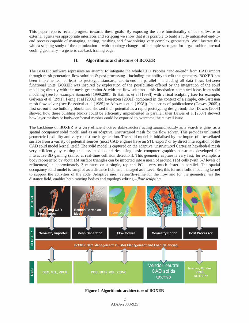
II. Algorithmic architecture of BOXER The BOXER software represents an attempt to integrate the whole CFD Process “end-to-end” from CAD import through mesh generation flow solution & post-processing - including the ability to edit the geometry. BOXER has been implemented, at least to prototype standard, end-to-end in parallel – including all data flows between functional units. BOXER was inspired by exploration of the possibilities offered by the integration of the solid modeling directly with the mesh generation & with the flow solution – this inspiration combined ideas from solid modeling (see for example Samareh [1999,2001] & Haimes et al [1998]) with virtual sculpting (see for example, Galyean et al [1991], Perng et al [2001] and Baeretzen [2001]) combined in the context of a simple, cut-Cartesian mesh flow solver ( see Bussoletti et al [1985] or Aftosmis et al [1998]). In a series of publications: (Dawes [2005]) first set out these building blocks and showed their potential as a rapid prototyping design tool; then Dawes [2006] showed how these building blocks could be efficiently implemented in parallel; then Dawes et al [2007] showed how layer meshes or body-conformal meshes could be exported to overcome the cut-cell issue. The backbone of BOXER is a very efficient octree data-structure acting simultaneously as a search engine, as a spatial occupancy solid model and as an adaptive, unstructured mesh for the flow solver. This provides unlimited geometric flexibility and very robust mesh generation. The solid model is initialised by the import of a tessellated surface from a variety of potential sources (most CAD engines have an STL export) or by direct interrogation of the CAD solid model kernel itself. The solid model is captured on the adaptive, unstructured Cartesian hexahedral mesh very efficiently by cutting the tesselated boundaries using basic computer graphics constructs developed for interactive 3D gaming (aimed at real-time collision detection). This geometry capture is very fast; for example, a body represented by about 1M surface triangles can be imported into a mesh of around 11M cells (with 6-7 levels of refinement) in approximately 2 minutes on a single, top-end PC – very much faster in parallel. The spatial occupancy solid model is sampled as a distance field and managed as a Level Set; this forms a solid modeling kernel to support the activities of the code. Adaptive mesh refine/de-refine for the flow and for the geometry, via the distance field, enables both moving bodies and topology editing – flow sculpting.
Figure 1 Algorithmic architecture of BOXER
AIAA-2008-925
3
The algorithmic architecture is illustrated in Figure 1. The associated 3D RANS solver was adapted from an existing unstructured mesh RANS solver (Dawes et al [2001]) with the additional complications of handling hanging nodes and the cut cells.
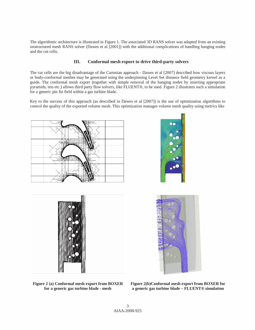
III. Conformal mesh export to drive third-party solvers The cut cells are the big disadvantage of the Cartesian approach - Dawes et al [2007] described how viscous layers or body-conformal meshes may be generated using the underpinning Level Set distance field geometry kernel as a guide. The conformal mesh export (together with simple removal of the hanging nodes by inserting appropriate pyramids, tets etc.) allows third party flow solvers, like FLUENT®, to be used. Figure 2 illustrates such a simulation for a generic pin fin field within a gas turbine blade. Key to the success of this approach (as described in Dawes et al [2007]) is the use of optimization algorithms to control the quality of the exported volume mesh. This optimization manages volume mesh quality using metrics like
Figure 2 (a) Conformal mesh export from BOXER
for a generic gas turbine blade - mesh
Figure 2(b)Conformal mesh export from BOXER for a generic gas turbine blade – FLUENT® simulation
AIAA-2008-925
4
skew, warpage, etc. – in fact whatever metrics the third-party solver is sensitive to – and the volume mesh is then “managed” into an acceptable range so the exported mesh is guaranteed of solvable quality. This is absolutely crucial for the success – indeed for the very viability – of an automated process aimed at real, complex geometries likely to undergo topological change during optimization. The trade-off for the guaranteed solvable volume mesh is that sometimes surface mesh smoothness is compromised; typically most of the surface is mirror-like but difficult areas distort - but by no more than a fraction of the fundamental smallest mesh scale (so whether a solver can see the distortion is a moot point). Much more work is still needed – and planned – in this area – especially to automate feature recognition and preservation.
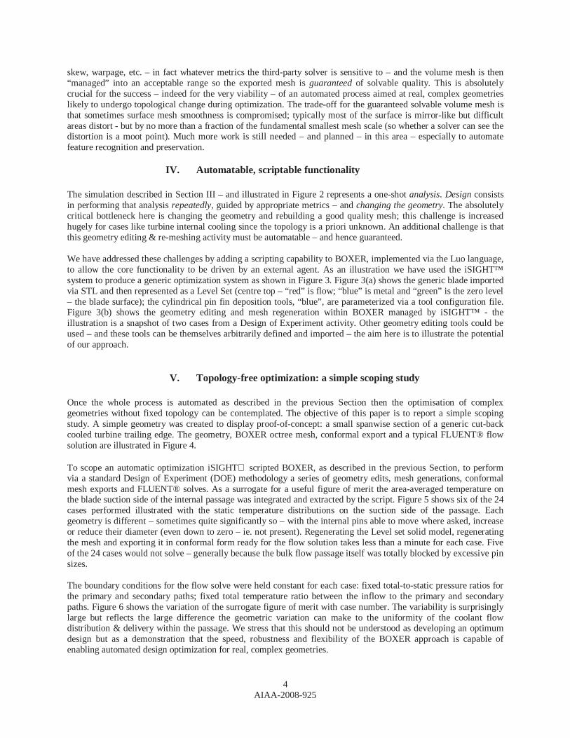
IV. Automatable, scriptable functionality The simulation described in Section III – and illustrated in Figure 2 represents a one-shot analysis. Design consists in performing that analysis repeatedly, guided by appropriate metrics – and changing the geometry. The absolutely critical bottleneck here is changing the geometry and rebuilding a good quality mesh; this challenge is increased hugely for cases like turbine internal cooling since the topology is a priori unknown. An additional challenge is that this geometry editing & re-meshing activity must be automatable – and hence guaranteed. We have addressed these challenges by adding a scripting capability to BOXER, implemented via the Luo language, to allow the core functionality to be driven by an external agent. As an illustration we have used the iSIGHT™ system to produce a generic optimization system as shown in Figure 3. Figure 3(a) shows the generic blade imported via STL and then represented as a Level Set (centre top – “red” is flow; “blue” is metal and “green” is the zero level – the blade surface); the cylindrical pin fin deposition tools, “blue”, are parameterized via a tool configuration file. Figure 3(b) shows the geometry editing and mesh regeneration within BOXER managed by iSIGHT™ - the illustration is a snapshot of two cases from a Design of Experiment activity. Other geometry editing tools could be used – and these tools can be themselves arbitrarily defined and imported – the aim here is to illustrate the potential of our approach.
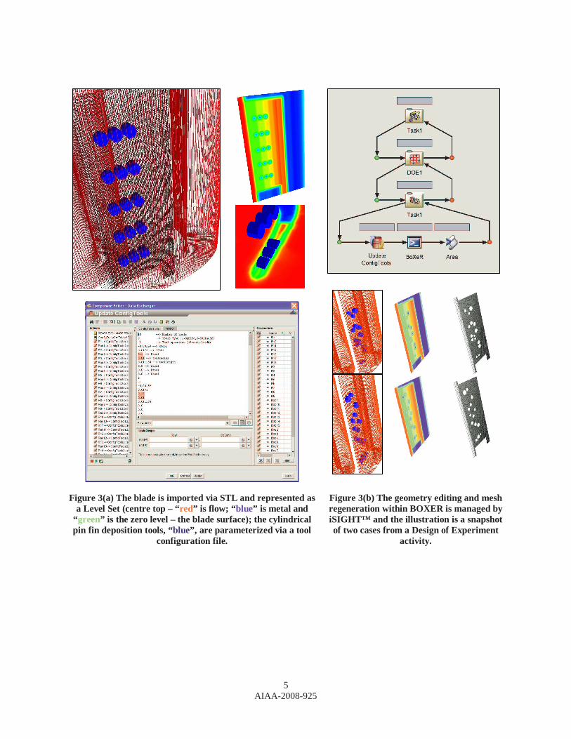
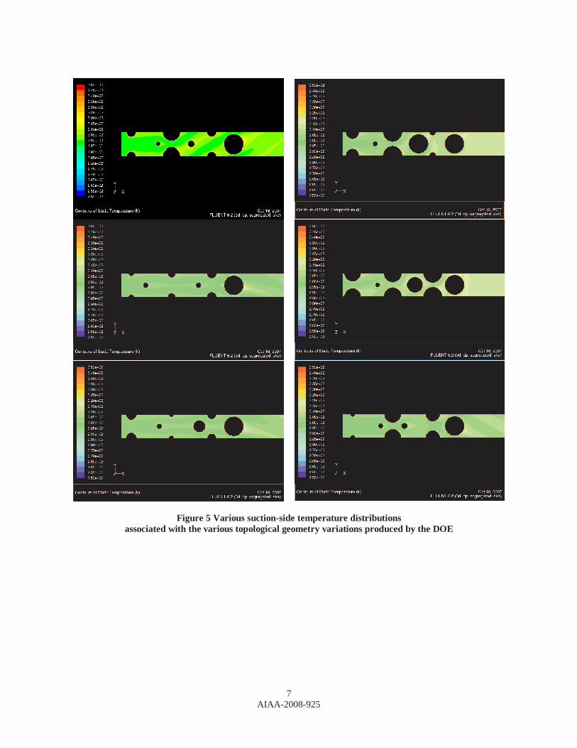
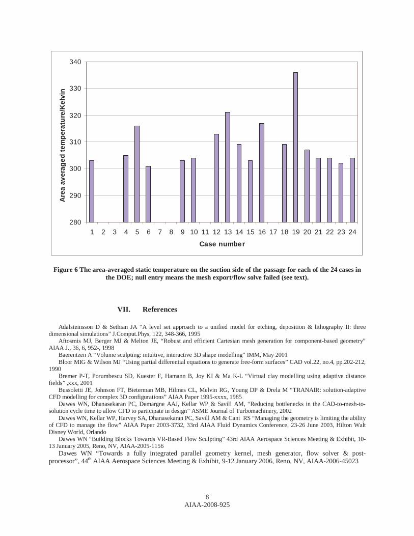
V. Topology-free optimization: a simple scoping study Once the whole process is automated as described in the previous Section then the optimisation of complex geometries without fixed topology can be contemplated. The objective of this paper is to report a simple scoping study. A simple geometry was created to display proof-of-concept: a small spanwise section of a generic cut-back cooled turbine trailing edge. The geometry, BOXER octree mesh, conformal export and a typical FLUENT® flow solution are illustrated in Figure 4. To scope an automatic optimization iSIGHT scripted BOXER, as described in the previous Section, to perform via a standard Design of Experiment (DOE) methodology a series of geometry edits, mesh generations, conformal mesh exports and FLUENT® solves. As a surrogate for a useful figure of merit the area-averaged temperature on the blade suction side of the internal passage was integrated and extracted by the script. Figure 5 shows six of the 24 cases performed illustrated with the static temperature distributions on the suction side of the passage. Each geometry is different – sometimes quite significantly so – with the internal pins able to move where asked, increase or reduce their diameter (even down to zero – ie. not present). Regenerating the Level set solid model, regenerating the mesh and exporting it in conformal form ready for the flow solution takes less than a minute for each case. Five of the 24 cases would not solve – generally because the bulk flow passage itself was totally blocked by excessive pin sizes. The boundary conditions for the flow solve were held constant for each case: fixed total-to-static pressure ratios for the primary and secondary paths; fixed total temperature ratio between the inflow to the primary and secondary paths. Figure 6 shows the variation of the surrogate figure of merit with case number. The variability is surprisingly large but reflects the large difference the geometric variation can make to the uniformity of the coolant flow distribution & delivery within the passage. We stress that this should not be understood as developing an optimum design but as a demonstration that the speed, robustness and flexibility of the BOXER approach is capable of enabling automated design optimization for real, complex geometries.
AIAA-2008-925
5
Figure 3(a) The blade is imported via STL and represented as
a Level Set (centre top – “red” is flow; “ blue” is metal and “ green” is the zero level – the blade surface); the cylindrical pin fin deposition tools, “blue”, are parameterized via a tool
configuration file.
Figure 3(b) The geometry editing and mesh regeneration within BOXER is managed by iSIGHT™ and the illustration is a snapshot of two cases from a Design of Experiment
activity.
AIAA-2008-925
6
Figure 4 A simple, generic cut-back trailing edge geometry (top left) with corresponding conformal export (bottom left) and predicted Mach numbers using the FLUENT® solver (right column).
VI. Concluding Remarks This paper has described recent extensions to the BOXER paradigm. In particular, it is shown that by adding a scripting capability to the core functionality it is possible to automate the modeling & meshing of complex geometries without fixed topology as the basis for design optimization – driven here by iSIGHT™. As a scoping study the new approach was applied to a generic cut-back trailing edge geometry in a classic DOE manner with a simple surrogate figure of merit. We stress that this study should not be understood as developing an optimum design but as a demonstration that the speed, robustness and flexibility of the BOXER approach is indeed capable of enabling automated design optimization for real, complex geometries. Currently application of the approach described in this paper is underway on a much more realistic case of a cooled turbine rotor with a trenched tip./winglet configuration.
AIAA-2008-925
7
Figure 5 Various suction-side temperature distributions associated with the various topological geometry variations produced by the DOE
AIAA-2008-925
8
280
290
300
310
320
330
340
1 2 3 4 5 6 7 8 9 10 11 12 13 14 15 16 17 18 19 20 21 22 23 24
Case number
Are
a av
erag
ed t
emp
erat
ure
/Kel
vin
Figure 6 The area-averaged static temperature on the suction side of the passage for each of the 24 cases in the DOE; null entry means the mesh export/flow solve failed (see text).
VII. References
Adalsteinsson D & Sethian JA “A level set approach to a unified model for etching, deposition & lithography II: three dimensional simulations” J.Comput.Phys, 122, 348-366, 1995
Aftosmis MJ, Berger MJ & Melton JE, “Robust and efficient Cartesian mesh generation for component-based geometry” AIAA J., 36, 6, 952-, 1998
Baerentzen A “Volume sculpting: intuitive, interactive 3D shape modelling” IMM, May 2001 Bloor MIG & Wilson MJ “Using partial differential equations to generate free-form surfaces” CAD vol.22, no.4, pp.202-212,
1990 Bremer P-T, Porumbescu SD, Kuester F, Hamann B, Joy KI & Ma K-L “Virtual clay modelling using adaptive distance
fields” ,xxx, 2001 Bussoletti JE, Johnson FT, Bieterman MB, Hilmes CL, Melvin RG, Young DP & Drela M “TRANAIR: solution-adaptive
CFD modelling for complex 3D configurations” AIAA Paper 1995-xxxx, 1985 Dawes WN, Dhanasekaran PC, Demargne AAJ, Kellar WP & Savill AM, “Reducing bottlenecks in the CAD-to-mesh-to-
solution cycle time to allow CFD to participate in design” ASME Journal of Turbomachinery, 2002 Dawes WN, Kellar WP, Harvey SA, Dhanasekaran PC, Savill AM & Cant RS “Managing the geometry is limiting the ability
of CFD to manage the flow” AIAA Paper 2003-3732, 33rd AIAA Fluid Dynamics Conference, 23-26 June 2003, Hilton Walt Disney World, Orlando
Dawes WN “Building Blocks Towards VR-Based Flow Sculpting” 43rd AIAA Aerospace Sciences Meeting & Exhibit, 10-13 January 2005, Reno, NV, AIAA-2005-1156
Dawes WN “Towards a fully integrated parallel geometry kernel, mesh generator, flow solver & post-processor”, 44th AIAA Aerospace Sciences Meeting & Exhibit, 9-12 January 2006, Reno, NV, AIAA-2006-45023
AIAA-2008-925
9
Dawes WN, Harvey SA, Fellows S, Favaretto CF & Vellivelli A “Viscous Layer Meshes from Level Sets on Cartesian Meshes”, 45th AIAA Aerospace Sciences Meeting & Exhibit, 8-11 January 2007, Reno, NV, AIAA-2007-0555
Delanaye M, Aftosmis MJ, Berger MJ, Liu Y & Pulliam TH “Automatic hybrid Cartesian grid generation for high Reynolds number flows around complex geometries” AIAA 99-0777, 37th AIAA Aerospace Sciences Meeting & Exhibit, 11-14 January 1999, Reno, NV
Galyean TA & Hughes JF “Sculpting: an interactive volumetric modelling technique” ACM Trans., Computer Graphics, vol.25, no.4, pp 267-274, 1991
Glassner AS “Graphics Gems” Academic Press, 1990+ Haimes R & Follen GL “Computational Analysis Programming Interface” Proc. 6th Int. Conf. On Numerical Grid
Generation in Computational Field Simulations, Eds. Cross, Eiseman, Hauser, Soni & Thompson, July 1998. Harvey SA, Dawes WN & Gallimore SJ “An Automatic Design Optimisation System for Axial Compressors Part I: Software
Development” ASME Paper GT2003-38115 Harvey SA, Dawes WN & Bolger JJ “An Automatic Design Optimisation System for Axial Compressors Part II:
Experimental Validation” ASME Paper GT2003-38650 Jones MW & Satherley R “Voxelisation: modelling for volume graphics” , xxx, 2000 Kallinderis Y & Ward S “Prismatic grid generation for three-dimensional complex geometries” AIAA Journal, Vol.31,
No.10, pp 1850- ,Oct.1993 Kellar WP, Savill AM & Dawes WN “Integrated CAD/CFD Visualisation of a Generic F1 Car Front Wheel Flowfield”
Lecture Notes in Computer Science, Vol 1593, 1999 Kellar WP “Geometry modelling in CFD and design optimisation” PhD Dissertation, Cambridge 2003 Lamousin HJ & Waggenspack WN “NURBS-based free-form deformation” IEEE Computer Graphics & Applications
Vol.14, No.6, 1994 Osher S & Sethian JA “Fronts propagating with curvature-dependent speed: algorithms based on Hamilton-Jacobi
formulations” J.Comput.Phys, 79, 12-, 1988 Perng K-L, Wang W-T, Flanagan M & Ouhyoung M “A real-time 3D virtual sculpting tool based on modified marching
cubes”, SIGGRAPH, 2001 Samareh, JA “Status & Future of Geometry Modelling and Grid Generation of Design and Optimisation” J.of Aircraft, Vol
36, no1, Feb 1999 Samareh JA “Survey of shape parameterisation techniques for high-fidelity multi-disciplinary shape optimisation” AIAA
Journal Vol.39, No.5, 2001 Sederberg TW & Parry SR “Free-form deformation of solid geometric models” Computer Graphics Vol.20, No.4, 1986 Sussman M, Smereka P & Osher S “A level set approach for computing solutions to incompressible two-phase flow”
J.Comput.Phys, 114, pp 146-159, 1994 Viecelli JA “A computing method for incompressible flows bounded by moving walls” J.Comput.Phys, 8, 119-, 1971 Wang ZJ & Chen RF “Anisotropic solution-adaptive viscous Cartesian grid method for turbulent flow simulation” AIAA
Journal, Vol.40, No.10, pp 1969-, Oct.2002 Yerry MA & Sheppard MS “Automatic three-dimensional mesh generation by the modified octree technique” Int.J.for
Num.Methods in Engineering, vol.20, 1965-1990,1983