Embed Size (px)
Citation preview
12 3
4
5 67
8 9
18 19
10 11
1216
1714 15
13 20 21 22 23 24 2526
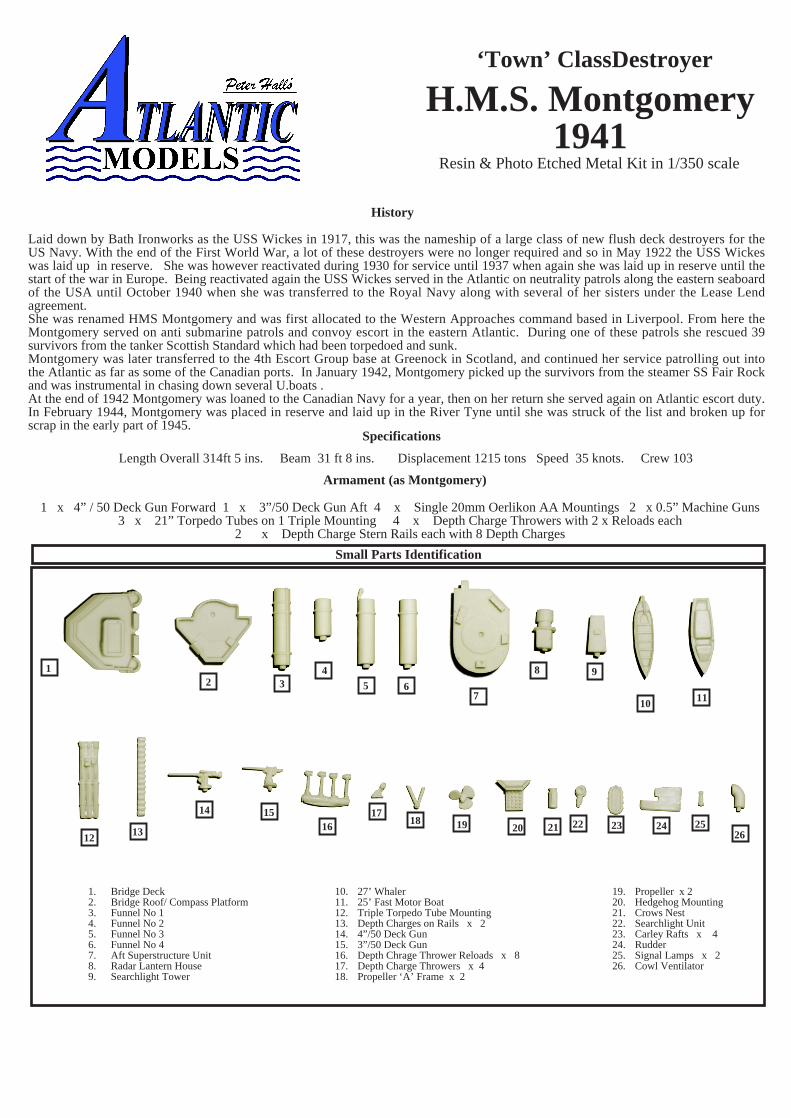
Small Parts Identification
1. Bridge Deck2. Bridge Roof/ Compass Platform3. Funnel No 14. Funnel No 25. Funnel No 36. Funnel No 47. Aft Superstructure Unit8. Radar Lantern House9. Searchlight Tower
10. 27’ Whaler11. 25’ Fast Motor Boat12. Triple Torpedo Tube Mounting13. Depth Charges on Rails x 214. 4”/50 Deck Gun15. 3”/50 Deck Gun16. Depth Chrage Thrower Reloads x 817. Depth Charge Throwers x 418. Propeller ‘A’ Frame x 2
19. Propeller x 220. Hedgehog Mounting21. Crows Nest22. Searchlight Unit23. Carley Rafts x 424. Rudder25. Signal Lamps x 226. Cowl Ventilator
History
Specifications
Length Overall 314ft 5 ins. Beam 31 ft 8 ins. Displacement 1215 tons Speed 35 knots. Crew 103
Armament (as Montgomery)
Laid down by Bath Ironworks as the USS Wickes in 1917, this was the nameship of a large class of new flush deck destroyers for theUS Navy. With the end of the First World War, a lot of these destroyers were no longer required and so in May 1922 the USS Wickeswas laid up in reserve. She was however reactivated during 1930 for service until 1937 when again she was laid up in reserve until thestart of the war in Europe. Being reactivated again the USS Wickes served in the Atlantic on neutrality patrols along the eastern seaboardof the USA until October 1940 when she was transferred to the Royal Navy along with several of her sisters under the Lease Lendagreement.She was renamed HMS Montgomery and was first allocated to the Western Approaches command based in Liverpool. From here theMontgomery served on anti submarine patrols and convoy escort in the eastern Atlantic. During one of these patrols she rescued 39survivors from the tanker Scottish Standard which had been torpedoed and sunk.Montgomery was later transferred to the 4th Escort Group base at Greenock in Scotland, and continued her service patrolling out intothe Atlantic as far as some of the Canadian ports. In January 1942, Montgomery picked up the survivors from the steamer SS Fair Rockand was instrumental in chasing down several U.boats .At the end of 1942 Montgomery was loaned to the Canadian Navy for a year, then on her return she served again on Atlantic escort duty.In February 1944, Montgomery was placed in reserve and laid up in the River Tyne until she was struck of the list and broken up forscrap in the early part of 1945.
1 x 4” / 50 Deck Gun Forward 1 x 3”/50 Deck Gun Aft 4 x Single 20mm Oerlikon AA Mountings 2 x 0.5” Machine Guns3 x 21” Torpedo Tubes on 1 Triple Mounting 4 x Depth Charge Throwers with 2 x Reloads each
2 x Depth Charge Stern Rails each with 8 Depth Charges
H.M.S. Montgomery1941
‘Town’ ClassDestroyer
Resin & Photo Etched Metal Kit in 1/350 scale
1 2 3 4
5
6
7
8
9
10
11
1213
14
15
16
1718
19
20
21
2223
24
24
25 26
2728 29 30
31
32
3334
3536 37
3839
40
41
43
4244
45
46 47
48
4950 51
5253 54
5556
57
1.M
ain
Dec
k R
aili
ngs
(Aft
)2.
Foc
’s’l
e R
aili
ngs
3.F
oc’s
’le
Rai
ling
s (O
ptio
nal)
4.A
ft S
uper
stru
ctur
e R
aili
ngs
5.A
ft S
uper
stru
ctur
e R
aili
ngs
(Can
vas
Dod
gers
)6.
Gal
ley
Roo
f R
aili
ngs
7.G
alle
y R
oof
Rai
ling
s (C
anva
s D
odge
rs)
8.27
’ W
hale
r T
hwar
ts9.
27’
Wha
ler
Oar
s an
d R
udde
r10
.V
erti
cal L
adde
r S
tock
11.
Bri
dge
Fro
nt D
F A
nten
na P
latf
orm
12.
Incl
ined
Lad
der
(Aft
Sup
erst
ruct
ure)
13.
Sea
rchl
ight
Tow
er P
latf
orm
14.
Aft
3”
Gun
Foo
tpla
te15
.28
6 R
adar
Ant
enna
Ass
embl
y
29.
Incl
ined
Lad
ders
(G
alle
y H
ouse
)30
.A
ncho
r C
hain
Sto
ck31
.In
clin
ed L
adde
r (B
ridg
e)32
.25
’ F
at M
otor
Boa
t Fit
ting
s33
.B
oat D
avit
s34
.20
mm
Oer
liko
n M
ount
ings
35.
US
N B
oat S
kid
Dav
its
36.
US
N B
oat S
kid
Fra
me
37.
US
N B
oat C
radl
e S
uppo
rts
38.
US
N B
oat C
radl
e B
race
s39
.T
orpe
do L
oadi
ng D
avit
40.
US
N S
tyle
Pro
p G
uard
s41
.D
C L
oadi
ng D
avit
s42
.B
ow A
ncho
r C
rane
43.
Incl
ined
Lad
der
(Bri
dge
Roo
f)44
.R
udde
r (A
lten
ativ
e)45
.A
ft C
ompa
ss C
over
Fra
me
46.
Pro
p G
uard
Sup
port
s (L
ate
Fit
Bri
tish
)47
.P
rop
Gua
rds
(Lat
e F
it B
riti
sh)
48.
Bri
dge
Win
dow
s49
.B
ridg
e S
cree
n (P
ort S
ide)
50.
Bri
dge
Scr
een
(Stb
d S
ide)
51.
Rad
ar L
ante
rn F
ram
e52
.0.
5” M
achi
ne G
uns
53.
4”/5
0 D
eck
Gun
Shi
eld
54.
3”/5
0 D
eck
Gun
Shi
eld
55.
Sea
rchl
ight
Tow
er (
Ear
ly U
SN
Sty
le)
56.
Sea
rchl
ight
Tow
er R
aili
ng57
.A
ft C
arle
y R
aft R
acks
16.
Shi
p B
oat R
etai
ning
Str
aps
17.
Mid
ship
s G
un P
latf
orm
Sup
port
s18
.M
idsh
ips
Gun
Pla
tfor
ms
19.
291
Rad
ar A
nten
na20
.A
ssor
ted
Spl
inte
r M
ats
21.
Fun
nel C
ap G
rill
s22
.F
ore
Mas
t Low
er Y
arda
rm23
.F
ore
Mas
t Upp
er Y
arda
rm24
.M
idsh
ips
Car
ley
Raf
t Sto
wag
e25
.A
ncho
r A
ssem
blys
26.
Lan
tern
Rad
ar P
latf
orm
27.
Dep
th C
harg
e R
ail F
ram
es28
.D
epth
Chr
age
Rai
ls
Gen
eral
Pre
cau
tion
sW
hen
ass
emb
lin
g a
Res
in /
Ph
otoe
tch
ed m
etal
kit
, cer
tain
pre
cau
tion
s m
ust
fir
st b
e ta
ken
.1.
Res
in d
ust
can
be
har
mfu
l if
inh
aled
. It
is r
ecom
men
ded
th
at y
ou w
ear
a su
itab
le d
ust
mas
k w
hen
dri
llin
g or
san
din
g re
sin
par
ts.
2. C
yan
o ad
hes
ives
(su
per
glu
es )
are
gen
eral
ly u
sed
to
asse
mb
le t
his
typ
e of
kit
. Car
e m
ust
be
tak
en w
hen
usi
ng
this
typ
e of
ad
hes
ive
as it
wil
l bon
d in
seco
nd
s. F
ollo
w t
he
advi
ce o
n t
he
con
tain
er.
3.W
ash
res
in p
arts
in a
sol
uti
on o
f w
arm
soa
py
wat
er b
efor
e as
sem
bly
. Th
is w
ill r
emov
e an
y re
sid
ual
mol
d r
elea
se a
gen
ts a
nd
en
sure
a g
ood
key
for
pai
nti
ng.
4. S
oak
ph
otoe
tch
par
ts in
a s
uit
able
sol
ven
t, s
uch
as
wh
ite
spir
it, t
o d
egre
ase
the
surf
aces
pri
or t
o p
ain
tin
g.
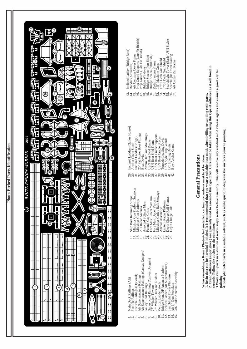
Pho
to E
tche
d P
arts
Ide
ntif
icat
ion
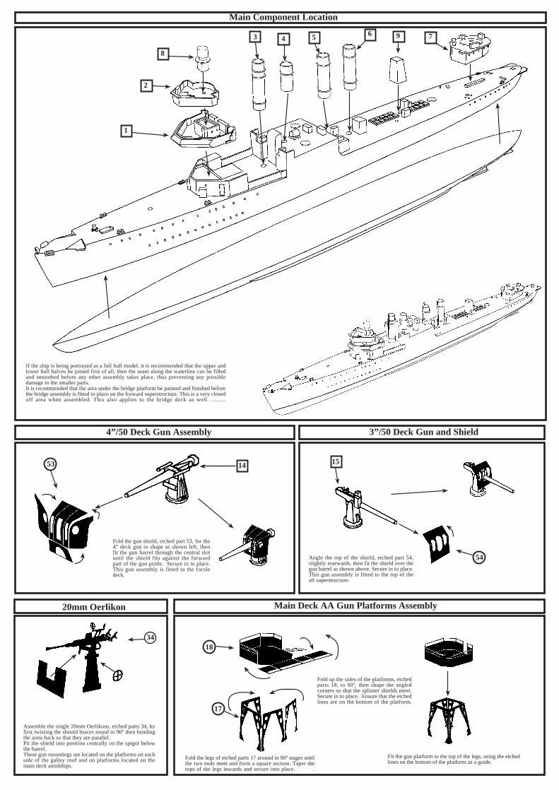
20mm Oerlikon
Assemble the single 20mm Oerlikons, etched parts 34, byfirst twisting the should braces round to 90º then bendingthe arms back so that they are parallel.Fit the shield into position centrally on the spigot belowthe barrel.These gun mountings are located on the platforms on eachside of the galley roof and on platforms located on themain deck amidships.
4”/50 Deck Gun Assembly 3”/50 Deck Gun and Shield
Main Deck AA Gun Platforms Assembly
Main Component Location
If the ship is being portrayed as a full hull model, it is recommended that the upper andlower hull halves be joined first of all, then the seam along the waterline can be filledand smoothed before any other assembly takes place, thus preventing any possibledamage to the smaller parts.It is recommended that the area under the bridge platform be painted and finished beforethe bridge assembly is fitted in place on the forward superstructure. This is a very closedoff area when assembled. This also applies to the bridge deck as well. .........
53
54
3418
17
1
2
8
3 4 5 6 9 7
14 15
Fold the gun shield, etched part 53, for the4” deck gun to shape as shown left, thenfit the gun barrel through the central slotuntil the shield fits against the forwardpart of the gun pintle. Secure in to place.This gun assembly is fitted to the focsledeck.
Angle the top of the shield, etched part 54,slightly rearwards, then fit the shield over thegun barrel as shown above. Secure in to place.This gun assembly is fitted to the top of theaft superstructure.
Fold up the sides of the platforms, etchedparts 18, to 90º, then shape the angledcorners so that the splinter shields meet.Secure in to place. Ensure that the etchedlines are on the bottom of the platform.
Fold the legs of etched parts 17 around in 90º stages untilthe two ends meet and form a square section. Taper thetops of the legs inwards and secure into place. .
Fit the gun platform to the top of the legs, using the etchedlines on the bottom of the platform as a guide.
286 Radar Antenna
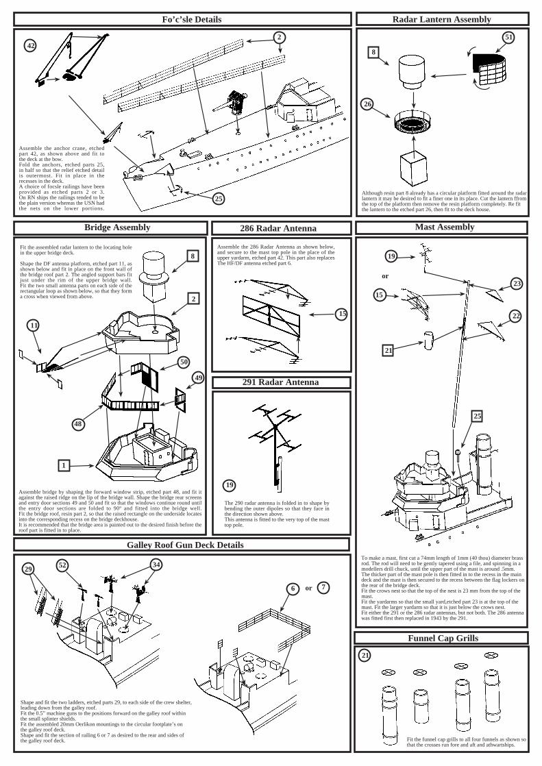
Assemble the 286 Radar Antenna as shown below,and secure to the mast top pole in the place of theupper yardarm, etched part 42. This part also replacesThe HF/DF antenna etched part 6.
291 Radar Antenna
The 290 radar antenna is folded in to shape bybending the outer dipoles so that they face inthe direction shown above.This antenna is fitted to the very top of the masttop pole.
Assemble the anchor crane, etchedpart 42, as shown above and fit tothe deck at the bow.Fold the anchors, etched parts 25,in half so that the relief etched detailis outermost. Fit in place in therecesses in the deck.A choice of focsle railings have beenprovided as etched parts 2 or 3.On RN ships the railings tended to bethe plain version whereas the USN hadthe nets on the lower portions.
Funnel Cap Grills
Galley Roof Gun Deck Details
Mast AssemblyBridge Assembly
Radar Lantern AssemblyFo’c’sle Details
345229
6 7
21
19
15
1
2
8
48
50
49
11
15
19
21
23
22
25
242
25
8
26
51
Although resin part 8 already has a circular platform fitted around the radarlantern it may be desired to fit a finer one in its place. Cut the lantern ffromthe top of the platform then remove the resin platform completely. Re fitthe lantern to the etched part 26, then fit to the deck house.
or
Assemble bridge by shaping the forward window strip, etched part 48, and fit itagainst the raised ridge on the lip of the bridge wall. Shape the bridge rear screensand entry door sections 49 and 50 and fit so that the windows continue round untilthe entry door sections are folded to 90º and fitted into the bridge well.Fit the bridge roof, resin part 2, so that the raised rectangle on the underside locatesinto the corresponding recess on the bridge deckhouse.It is recommended that the bridge area is painted out to the desired finish before theroof part is fitted in to place.
Fit the assembled radar lantern to the locating holein the upper bridge deck.
Shape the DF antenna platform, etched part 11, asshown below and fit in place on the front wall ofthe bridge roof part 2. The angled support bars fitjust under the rim of the upper bridge wall.Fit the two small antenna parts on each side of therectangular loop as shown below, so that they forma cross when viewed from above.
To make a mast, first cut a 74mm length of 1mm (40 thou) diameter brassrod. The rod will need to be gently tapered using a file, and spinning in amodellers drill chuck, until the upper part of the mast is around .5mm.The thicker part of the mast pole is then fitted in to the recess in the maindeck and the mast is then secured to the recess between the flag lockers onthe rear of the bridge deck.Fit the crows nest so that the top of the nest is 23 mm from the top of themast.Fit the yardarms so that the small yard,etched part 23 is at the top of themast. Fit the larger yardarm so that it is just below the crows nest.Fit either the 291 or the 286 radar antennas, but not both. The 286 antennawas fitted first then replaced in 1943 by the 291.
or
Shape and fit the two ladders, etched parts 29, to each side of the crew shelter,leading down from the galley roof.Fit the 0.5” machine guns to the positions forward on the galley roof withinthe small splinter shields.Fit the assembled 20mm Oerlikon mountings to the circular footplate’s onthe galley roof deck.Shape and fit the section of railing 6 or 7 as desired to the rear and sides ofthe galley roof deck. Fit the funnel cap grills to all four funnels as shown so
that the crosses run fore and aft and athwartships.
Boats Assembly
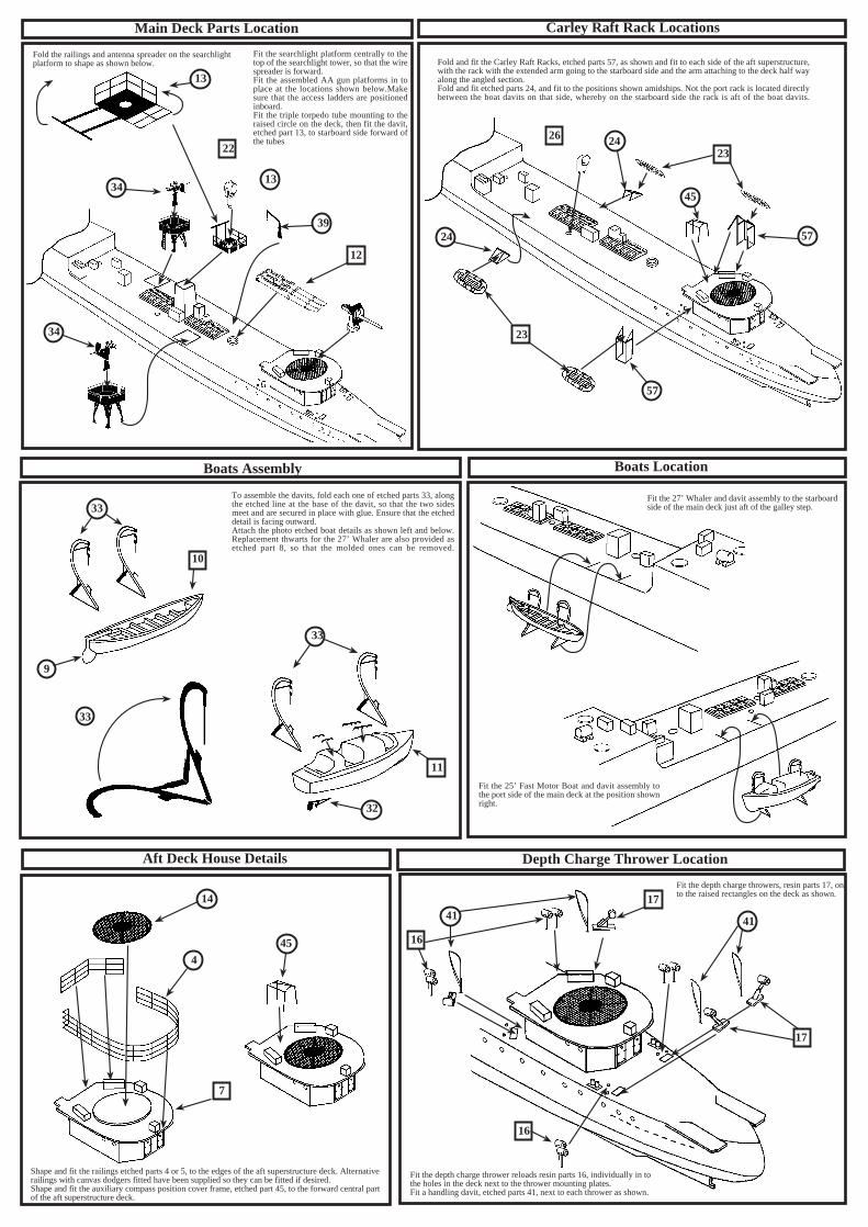
To assemble the davits, fold each one of etched parts 33, alongthe etched line at the base of the davit, so that the two sidesmeet and are secured in place with glue. Ensure that the etcheddetail is facing outward.Attach the photo etched boat details as shown left and below.Replacement thwarts for the 27’ Whaler are also provided asetched part 8, so that the molded ones can be removed.
33
Fold and fit the Carley Raft Racks, etched parts 57, as shown and fit to each side of the aft superstructure,with the rack with the extended arm going to the starboard side and the arm attaching to the deck half wayalong the angled section.Fold and fit etched parts 24, and fit to the positions shown amidships. Not the port rack is located directlybetween the boat davits on that side, whereby on the starboard side the rack is aft of the boat davits.
Depth Charge Thrower LocationAft Deck House Details
Boats Location
Carley Raft Rack LocationsMain Deck Parts Location
13
34
34
22
13
39
12
26 24
24
23
23
45
57
57
33
33
10
11
32
14
4
7
45 16
16
17
1741 41
Fold the railings and antenna spreader on the searchlightplatform to shape as shown below.
Fit the searchlight platform centrally to thetop of the searchlight tower, so that the wirespreader is forward.Fit the assembled AA gun platforms in toplace at the locations shown below.Makesure that the access ladders are positionedinboard.Fit the triple torpedo tube mounting to theraised circle on the deck, then fit the davit,etched part 13, to starboard side forward ofthe tubes
.
9
Fit the 27’ Whaler and davit assembly to the starboardside of the main deck just aft of the galley step.
Fit the 25’ Fast Motor Boat and davit assembly tothe port side of the main deck at the position shownright.
Shape and fit the railings etched parts 4 or 5, to the edges of the aft superstructure deck. Alternativerailings with canvas dodgers fitted have been supplied so they can be fitted if desired.Shape and fit the auxiliary compass position cover frame, etched part 45, to the forward central partof the aft superstructure deck.
Fit the depth charge throwers, resin parts 17, onto the raised rectangles on the deck as shown.
Fit the depth charge thrower reloads resin parts 16, individually in tothe holes in the deck next to the thrower mounting plates.Fit a handling davit, etched parts 41, next to each thrower as shown.
Boat Skids Assembly
Carefully assemble the two sets of boat skids as shown left.The starboard side set is slightly different to the port sideset in that it has an extended rear rail which attaches to thecentre superstructure. The outer supports are also locatedslightly differently to ensure correct positioning.
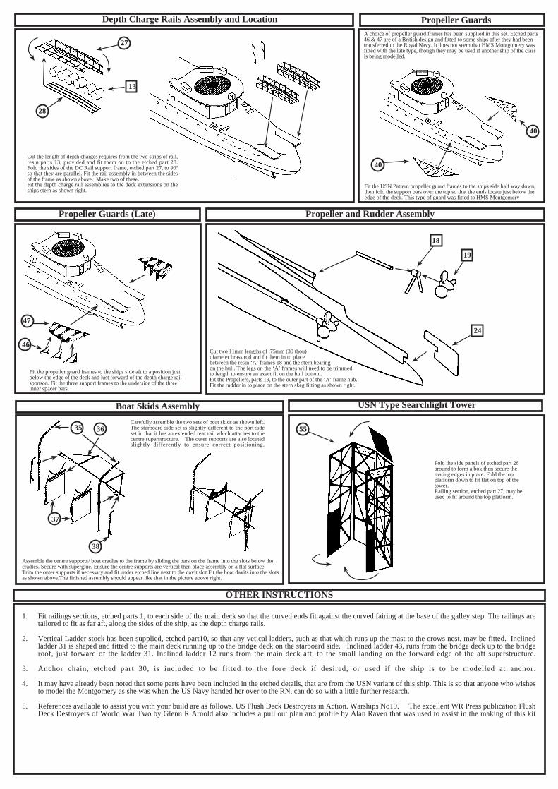
Assemble the centre supports/ boat cradles to the frame by sliding the bars on the frame into the slots below thecradles. Secure with superglue. Ensure the centre supports are vertical then place assembly on a flat surface.Trim the outer supports if necessary and fit under etched line next to the davit slot.Fit the boat davits into the slotsas shown above.The finished assembly should appear like that in the picture above right.
Fold the side panels of etched part 26around to form a box then secure themating edges in place. Fold the topplatform down to fit flat on top of thetower.Railing section, etched part 27, may beused to fit around the top platform.
A choice of propeller guard frames has been supplied in this set. Etched parts46 & 47 are of a British design and fitted to some ships after they had beentransferred to the Royal Navy. It does not seem that HMS Montgomery wasfitted with the late type, though they may be used if another ship of the classis being modelled.
Fit the propeller guard frames to the ships side aft to a position justbelow the edge of the deck and just forward of the depth charge railsponson. Fit the three support frames to the underside of the threeinner spacer bars.
Fit the USN Pattern propeller guard frames to the ships side half way down,then fold the support bars over the top so that the ends locate just below theedge of the deck. This type of guard was fitted to HMS Montgomery
USN Type Searchlight Tower
Propeller and Rudder AssemblyPropeller Guards (Late)
Propeller GuardsDepth Charge Rails Assembly and Location
OTHER INSTRUCTIONS
27
28
13
40
46
47
18
19
24
55
37
35 36
38
40
Cut the length of depth charges requires from the two strips of rail,resin parts 13, provided and fit them on to the etched part 28.Fold the sides of the DC Rail support frame, etched part 27, to 90ºso that they are parallel. Fit the rail assembly in between the sidesof the frame as shown above. Make two of these.Fit the depth charge rail assemblies to the deck extensions on theships stern as shown right.
Cut two 11mm lengths of .75mm (30 thou)diameter brass rod and fit them in to placebetween the resin ‘A’ frames 18 and the stern bearingon the hull. The legs on the ‘A’ frames will need to be trimmedto length to ensure an exact fit on the hull bottom.Fit the Propellers, parts 19, to the outer part of the ‘A’ frame hub.Fit the rudder in to place on the stern skeg fitting as shown right.
1. Fit railings sections, etched parts 1, to each side of the main deck so that the curved ends fit against the curved fairing at the base of the galley step. The railings aretailored to fit as far aft, along the sides of the ship, as the depth charge rails.
2. Vertical Ladder stock has been supplied, etched part10, so that any vetical ladders, such as that which runs up the mast to the crows nest, may be fitted. Inclinedladder 31 is shaped and fitted to the main deck running up to the bridge deck on the starboard side. Inclined ladder 43, runs from the bridge deck up to the bridgeroof, just forward of the ladder 31. Inclined ladder 12 runs from the main deck aft, to the small landing on the forward edge of the aft superstructure.
3. Anchor chain, etched part 30, is included to be fitted to the fore deck if desired, or used if the ship is to be modelled at anchor.
4. It may have already been noted that some parts have been included in the etched details, that are from the USN variant of this ship. This is so that anyone who wishesto model the Montgomery as she was when the US Navy handed her over to the RN, can do so with a little further research.
5. References available to assist you with your build are as follows. US Flush Deck Destroyers in Action. Warships No19. The excellent WR Press publication FlushDeck Destroyers of World War Two by Glenn R Arnold also includes a pull out plan and profile by Alan Raven that was used to assist in the making of this kit
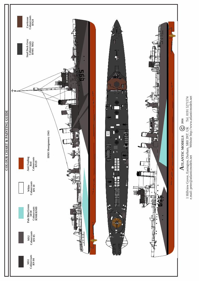
MS
1C
olou
rcoa
tsR
N 0
4
MS
2C
olou
rcoa
tsR
N 0
5
Pal
e B
lue/
Gre
en50
/50
Col
ourc
oats
RN
08/R
N09
Wh
ite
Col
ourc
oats
RN
10
An
ti F
ouli
ng
Red
Col
ourc
oats
RN
19
Ste
el D
eck
Gre
yC
olou
rcoa
tsR
N05
MS
2
Cor
tice
ne
Col
ourc
oats
RN
24
CO
LO
UR
CH
AR
T &
PA
INT
ING
GU
IDE
HM
S M
ontg
omer
y 19
43
1 H
illvi
ew G
rove
, Eas
ingt
on, D
urha
m, S
R8
3NT
. UK
Tel
. 019
1 52
7157
4e.
mai
l: pe
ter@
atla
ntic
mod
els.
net
Web
site
http
://w
ww
.atla
ntic
mod
els.
net
CA
TL
AN
TIC
MO
DE
LS
2016


![H.M.S.&Alexander&&& · [H.M.S.&ALEXANDER’S&MARINE0GRENADIERS&RE0ENACTMENTUNIT(PART&OF&H.R.G.M)]& &&&&&H.M.S.&Alexander&&& 179801800&! Andrea’Portelli’ [13.02.2011]’](https://img.pdfslide.net/doc/110x75/6029bc0108f7174c4e2920a1/hmsalexander-hmsalexanderasmarine0grenadiersre0enactmentunitpartofhrgm.jpg)