Embed Size (px)
Citation preview

1
TOWN OF MIDLAND
ENGINEERING DEVELOPMENT DESIGN STANDARDS
Revised December 2012
2
TABLE OF CONTENTS
1.0 DESIGN SUBMISSIONS 9 1.1 General ..............................................................................................................................9 1.2 Definitions........................................................................................................................... 9 1.3 Submissions to Government Agencies ............................................................................... 10 1.4 Pre-Servicing for Subdivision Development ...................................................................... 10 1.5 Subdivision Agreement Schedules ..................................................................................... 11 1.6 Administration Fees, Securities, Development Charges ..................................................... 12 1.7 First Submission to the Engineering Department ............................................................... 12 1.8 Interim Submissions............................................................................................................ 13 1.9 Second and Subsequent Submissions ................................................................................. 13 1.10 Final Submissions to the Engineering Department .........................................................14 1.11 Attachments ....................................................................................................................15 1.12 Engineering Drawings ....................................................................................................15 1.13 Approval of Originals .....................................................................................................16 1.14 Other Approvals ..............................................................................................................16 2.0 DRAWINGS 16 2.1 Specifications for Engineering Drawings: ......................................................................16
a) Format ......................................................................................................... 16 b) Materials for Final Submission and “as-constructed” drawings ................. 16 c) Materials for Preliminary Submissions ....................................................... 16
2.2 Quality.............................................................................................................................17 2.3 Drawing Sheet Sizes .......................................................................................................17 2.4 Scales ..............................................................................................................................17 2.5 Basic Information ............................................................................................................17 2.6 Sewer Details ..................................................................................................................18 2.7 Watermain Details ..........................................................................................................18 2.8 Road Details ....................................................................................................................19 2.9 Miscellaneous Details .....................................................................................................19 2.10 Lot Grading Plan .............................................................................................................19 2.11 Sanitary and Storm Drainage Plans ................................................................................19 2.12 Engineering Surveys .......................................................................................................19 2.13 Signs ................................................................................................................................19 2.14 Water ...............................................................................................................................20 3.0 GENERAL PLANS 20 3.1 General Servicing Plans ..................................................................................................20 3.2 Storm Drainage Plans .....................................................................................................21 3.3 Grading Plans ..................................................................................................................21 3.4 Plan-Profile Drawings .....................................................................................................22 3.5 Erosion and Sediment Control Plans ..............................................................................22 3.6 Park Development ...........................................................................................................22 3.7 Trails and Walkways .......................................................................................................23 3.8 Landscaping ....................................................................................................................23 3.9 “As-Constructed” Drawings ...........................................................................................24
a) Road System ....................................................................................................... 24 b) Storm System ...................................................................................................... 25 c) Sanitary System .................................................................................................. 25 d) Water System ...................................................................................................... 26

3
e) Lot Grading ......................................................................................................... 26 4.0 ROADWAYS 26 4.1 Provincial Standards .......................................................................................................26 4.2 General ............................................................................................................................27 4.3 Clearing and Grubbing ....................................................................................................29 4.4 Grading ...........................................................................................................................29 4.5 Base Construction ...........................................................................................................29 4.6 Sub-Drains ......................................................................................................................29 4.7 Curb and Gutter ...............................................................................................................30 4.8 Ditches and Culverts .......................................................................................................30 4.9 Asphalt ............................................................................................................................30 4.10 Special Road Designs .....................................................................................................31 4.11 Builders Road..................................................................................................................31 4.12 Driveways ......................................................................................................................31 4.13 Street Name Signs ...........................................................................................................32 4.14 Traffic Signs....................................................................................................................32 4.15 Pavement Markings ........................................................................................................33 4.16 Geotechnical Engineering Requirements ........................................................................33 4.17 Inspection - Consultants ..................................................................................................33 5.0 STORM DRAINAGE SYSTEM 35 5.1 General ............................................................................................................................35
5.1.1 Required System ............................................................................................. 35 5.1.2 Service Area .................................................................................................... 35 5.1.3 Minor System .................................................................................................. 36 5.1.4 Major System .................................................................................................. 36 5.1.5 Sewers General ............................................................................................... 36
5.2 Stormwater Management ................................................................................................36 a) Stormwater Lot Level Controls .......................................................................... 36 b) Stormwater Conveyance Controls ...................................................................... 37 c) End-of-pipe Stormwater Controls ....................................................................... 37
5.2.1 Stormwater Management Requirements ......................................................... 37 5.2.2 On-Site Stormwater Management Reports ..................................................... 37 5.2.3 Quality Control ............................................................................................... 38 5.2.4 Hydrologic and Hydraulic Studies .................................................................. 38 5.2.5 Meteorology .................................................................................................... 39
5.3 Sewer Design ..................................................................................................................40 5.3.1 Hydraulic Design ............................................................................................ 40 5.3.2 Run-off Calculations ....................................................................................... 40 5.3.3 Intensity of Rainfall ........................................................................................ 42 5.3.4 Time of Concentration .................................................................................... 42 5.3.5 Pre-Development ............................................................................................ 42 5.3.6 Post-Development ........................................................................................... 42 5.3.7 Drainage Area ................................................................................................. 42 5.3.8 Sewer Material ................................................................................................ 42
5.4 System Layout ................................................................................................................43 5.4.1 Storm Sewer Requirements ............................................................................. 44
a) Trunk Sewer System ........................................................................................... 44 b) Pipe Capacities .................................................................................................... 44 c) Flow Velocities (Flowing full) ............................................................................ 45

4
d) Minimum Sizes ................................................................................................... 45 e) Depth of Storm Sewers ....................................................................................... 45 f) Location .............................................................................................................. 45 g) Radius Pipes ........................................................................................................ 45 h) Limits of Construction ........................................................................................ 45 i) Sewer Alignment ................................................................................................ 45 j) Changes in Pipe Size ........................................................................................... 46 k) Standard Easement Requirements....................................................................... 46 l) Testing and Acceptance ...................................................................................... 46
5.4.2 Maintenance Hole Requirements .................................................................... 46 a) Location and Spacing .......................................................................................... 46 b) Head Losses and Drops ....................................................................................... 47
5.4.3 Catchbasin Requirements ................................................................................ 47 a) Location and Spacing .......................................................................................... 47 b) Catchbasins Types .............................................................................................. 48 c) Catchbasins Leads ............................................................................................... 48 d) Frame and Grate .................................................................................................. 48
5.4.4 Roof Leaders, Foundation Drains and Storm Connections ............................ 48 5.4.5 Channel, Culvert and Overland Flow ............................................................. 49
5.5 Open Channels ................................................................................................................49 5.6 Open Ditches ...................................................................................................................49 5.7 Watercourse Erosion and Bank Stability ........................................................................50 5.8 Overland Flow Routes ....................................................................................................51 5.9 Inlet/Outlet Structures .....................................................................................................51 5.10 Maintenance ....................................................................................................................52 6.0 SANITARY DRAINAGE SYSTEM 52 6.1 General ............................................................................................................................52
6.1.1 Required System ............................................................................................. 52 6.1.2 Service Area .................................................................................................... 52 6.1.3 Drains .............................................................................................................. 52 6.1.4 Design Flows .................................................................................................. 53
6.2 Sanitary Sewers ...............................................................................................................53 6.2.1 Sewer Design .................................................................................................. 53 6.2.2 System Layout ................................................................................................ 54 6.2.3 Materials ......................................................................................................... 55 6.2.4 Testing of Sewers and Manholes .................................................................... 55 6.2.5 Service Connections ........................................................................................ 55 6.2.6 Maintenance .................................................................................................... 55 6.2.7 Maintenance Holes .......................................................................................... 55 6.2.8 Limits of Construction .................................................................................... 56
7.0 SIDEWALKS AND WALKWAYS 56 7.1 Sidewalks ........................................................................................................................56 7.2 Walkways ........................................................................................................................56 7.3 Pedestrian Ways ..............................................................................................................57
7.3.1 Trailways......................................................................................................... 57 7.3.2 Intersections .................................................................................................... 57 7.3.3 Boulevards ...................................................................................................... 57
8.0 STREET LIGHTING 57 8.1 Lighting Levels and Uniformity Ratio ............................................................................58

5
8.2 Approval and Construction .............................................................................................61 9.0 GRADING AND LANDSCAPING 61 9.1 General ............................................................................................................................61 9.2 Overall Grading Plan ......................................................................................................61 9.3 Tree Planting ...................................................................................................................61
9.3.1 General Streetscape Standards ........................................................................ 62 9.3.2 Notes for Streetscape Submission Drawings .................................................. 62 9.3.3 List of Details and Specifications ................................................................... 63 9.3.4 Minor Road Street Trees ................................................................................. 63 9.3.5 Corner Lot Treatments .................................................................................... 63 9.3.6 General Planting Considerations for Internal Streets ...................................... 63 9.3.7 Standard and Guidelines for Naturalization Areas ......................................... 64 9.3.8 Notes for Naturalization Submission Drawings ............................................. 64
9.4 Sodding & Seeding .........................................................................................................64 9.5 Lot Development Plans ...................................................................................................65 9.6 Fencing ............................................................................................................................65 10.0 EROSION AND SEDIMENT CONTROL 65 10.1 General ............................................................................................................................65 10.2 Catchbasin Sediment Control .........................................................................................66 10.3 Stone Pad Construction Entrance – Construction Access ...............................................66 10.4 Utilities ............................................................................................................................66 10.5 Canada Post .....................................................................................................................66 11.0 WATER SYSTEM 66 11.1 Supply System ................................................................................................................67
11.1.1 Source ............................................................................................................. 67 11.1.2 Type of System ............................................................................................... 68 11.1.3 Reservoir ......................................................................................................... 68 11.1.4 High Lift Pumps and Controls ........................................................................ 69 11.1.5 Building........................................................................................................... 69 11.1.6 Process Piping and Plumbing.......................................................................... 71 11.1.7 Electrical ......................................................................................................... 71 11.1.8 Property and Access ........................................................................................ 72 11.1.9 Water Quality and Treatment .......................................................................... 72 11.1.10 Standby Power ............................................................................................ 72 11.1.11 Operating Manual ....................................................................................... 73
11.2 Distribution System ........................................................................................................73 11.2.1 General ............................................................................................................ 73 11.2.2 Service Area .................................................................................................... 73 11.2.3 Design Flows .................................................................................................. 74 11.2.4 Selection of Main sizes and Pressures ............................................................ 74 11.2.5 Oversizing ....................................................................................................... 75 11.2.6 Layout Details ................................................................................................. 75
a) Watermains ......................................................................................................... 75 b) Hydrants .............................................................................................................. 75 c) Valves ................................................................................................................. 76 d) Service Connections ............................................................................................ 76 e) Restraining Watermain ....................................................................................... 76 f) Fittings ................................................................................................................ 77 g) Watermain Offsets .............................................................................................. 77

6
h) Service Saddles ................................................................................................... 77 i) Tappings .............................................................................................................. 77 j) Watermain Bedding ............................................................................................ 78 k) Pipe Deflection.................................................................................................... 79 l) Protection of Existing Utilities............................................................................ 79 m) Temporary Connection ................................................................................... 79 n) Initial Tie-In ........................................................................................................ 80
11.3 Swabbing/Charging the Watermain ................................................................................80 11.4 Pressure Testing ..............................................................................................................81 11.5 Chlorinating ....................................................................................................................81 11.6 Flushing...........................................................................................................................82 11.7 Sampling .........................................................................................................................83 11.8 Continuity Test................................................................................................................84 11.9 Tie-Ins .............................................................................................................................84 11.10 Maintenance ....................................................................................................................84 11.11 Materials .........................................................................................................................84
11.11.1 General ........................................................................................................ 84 11.11.2 Watermain ................................................................................................... 84 11.11.3 Service Connections and Meters ................................................................. 85 11.11.4 Hydrants ...................................................................................................... 85 11.11.5 Valves ......................................................................................................... 85 11.11.6 Specifications .............................................................................................. 85
11.12 Residential Domestic Water Services .............................................................................86 11.12.1 Design ......................................................................................................... 86 11.12.2 Installation................................................................................................... 86 11.12.3 Residential Service Specifications .............................................................. 87 11.12.4 Residential Service Inspections .................................................................. 88 11.12.5 Procedure for Pressure Testing Residential Water Services ....................... 88 11.12.6 Water Service Repair Procedure ................................................................. 89 11.12.7 Assumed Subdivision ................................................................................. 89 11.12.8 Unassumed Subdivision .............................................................................. 89 11.12.9 Residential Water Meters ............................................................................ 89 11.12.10 Care of Water Meters .................................................................................. 90 11.12.11 Approval of Water Meters .......................................................................... 90 11.12.12 Location of Water Meters ........................................................................... 90 11.12.13 Remote Wire Installation/Inspection .......................................................... 90 11.12.14 Failure to Register Properly ........................................................................ 90 11.12.15 Testing......................................................................................................... 90 11.12.16 Dispute Test of Water Meters ..................................................................... 90 11.12.17 Discontinue the Supply ............................................................................... 91 11.12.18 Draining the Plumbing ................................................................................ 91
11.13 Not For Resale ................................................................................................................91 11.14 Specifications for General Services, Domestic, and Fire Services .................................91 11.15 Watermain Installation Charges ......................................................................................92 11.16 Water Meter Costs ..........................................................................................................92 11.17 Water Service Inspection (Residential Only) .................................................................92 11.18 Installation/Removal of Hydrant Valve for Testing/Filling ............................................92 11.19 Painting Hydrants............................................................................................................93 11.20 Operation of Main Valve for Filling Watermain/Service ...............................................93

7
11.21 Fire Protection Charges ...................................................................................................93 11.22 Plans ................................................................................................................................93 11.23 Approvals ........................................................................................................................94 11.24 MOE Approvals ..............................................................................................................95 11.25 Inspection ........................................................................................................................95 11.26 Contractor’s Supervision ................................................................................................96 11.27 Liability Insurance ..........................................................................................................96 11.28 Installation and Construction ..........................................................................................96 11.29 Watermain and Appurtenances .......................................................................................96 11.30 Tracer Wire .....................................................................................................................97
PUBLIC WORKS DEPARTMENT - LOT GRADING GUIDELINES 1.0 LOT DEVELOPMENT PLAN – REQUIRED DETAILS 98 1.1 Lot Grading - Design Criteria .........................................................................................99 1.2 Lot Site Grading ............................................................................................................101
1.2.1 Grading Submission Procedure..................................................................... 101 1.2.2 Lot Grading Inspection and Certification ..................................................... 101
1.3 Landscaping Implementation Procedures .....................................................................102 1.4 Streetscape Works .........................................................................................................102 1.5 Naturalization Works ....................................................................................................103 1.6 Maintenance Agreement for Naturalization Areas .......................................................103 1.7 Retaining Walls .............................................................................................................106 1.8 Block Grading ...............................................................................................................106 1.9 Block Grading Criteria ..................................................................................................107 1.10 Ground Cover ................................................................................................................107
PUBLIC WORKS DEPARTMENT - INTERIM GUIDELINES FOR DEVELOPMENTS WITHIN
THE LITTLE LAKE WATERSHED 1.0 GENERAL 107 2.0 LAND USE PLANNING 108 3.0 STORM DRAINAGE SYSTEM 108 3.1 Drainage Ditches ...........................................................................................................108 3.2 Infiltration Systems .......................................................................................................108 3.3 Filter Strips....................................................................................................................108 3.4 Roof Drain Dry Well ....................................................................................................109
4.0 STORMWATER MANAGEMENT FACILITY 109 5.0 CONSTRUCTION PRACTICES 110
PUBLIC WORKS DEPARTMENT - POLICY MANUAL
1.0 WINTER MAINTENANCE 113 1.1 SNOW PLOWING OF STREETS ...............................................................................113
(a) Initial Call-out ............................................................................................... 113 (b) Priority of Streets: ......................................................................................... 113
1.2 SNOW PLOWING OF SIDEWALKS .........................................................................114 (a) PLOWING: ................................................................................................... 114 (b) PRIORITY OF SIDWALKS ........................................................................ 114 (c) SIDEWALK SANDING:.............................................................................. 114 (d) PLOWED LEVEL ON SIDEWALKS: ........................................................ 114
8
(e) SNOW REMOVAL ON KING STREET SIDEWALKS: ........................... 114 1.3 SNOW REMOVAL: .....................................................................................................114
2.0 SEWER LATERALS 115 2.1 INSTALLATION OF NEW SEWER LATERALS: ....................................................115 2.2. MAINTENANCE OF EXISTING SEWER LATERALS ............................................116
3.0 PRIVATE DRIVEWAYS 117 3.1 NEW DRIVEWAYS: ...................................................................................................117 3.2 DRIVEWAY MAINTENANCE: .................................................................................117 3.3 DRIVEWAY RECONSTRUCTION ............................................................................117 3.4 PAYMENT ...................................................................................................................118 3.5 DRIVEWAY CONSTRUCTION BY OWNER: ..........................................................118
4.0 PLANTING, CARE AND REMOVAL OF TREES 118 4.1 DEFINITIONS:.............................................................................................................118 4.2 GOVERNING BODY: .................................................................................................118 4.3 PLANTING TREES: ....................................................................................................119 4.4 CARE OF TREES.........................................................................................................120 4.5 REMOVAL OF TREES ...............................................................................................120 4.6 PENALTIES .................................................................................................................120
5.0 INSTALLATION AND REPAIR OF SERVICES 120 5.1 OBJECTIVE: ................................................................................................................120 5.2 DEFINITIONS:.............................................................................................................120 5.3 EXCAVATIONS FOR NEW SERVICES: ..................................................................121 5.4 EXCAVATIONS TO REPAIR EXISTING SERVICES: ............................................121 5.5 WORK PROCEEDING WITHOUT PERMIT:............................................................121 5.6 CUT REPORT SHEETS REQUIRED: ........................................................................121
9
ENGINEERING DEVELOPMENT DESIGN STANDARDS 1.0 DESIGN SUBMISSIONS 1.1 General
Development servicing designs prepared by the Developer’s Consulting Engineer are reviewed by the Public Works Department and the Midland Power Utility Corporation with the assistance of the Town Engineering Consultants. The review procedure is set out below. Incomplete submissions which do not attempt to address all aspects of the draft conditions or design standards may be returned with a request to complete the documentation. Standards are to be read in conjunction with the Ontario Provincial Standard.
1.2 Definitions
In this specification, the following definitions shall apply:
“Town” shall mean the Town of Midland.
“Contractor” shall mean the firm of Contractors, the company or individual acting as the Contractor and having entered into a contract with the Developer/Owner to install the services.
“Developer(s)/Owner(s)” shall mean the person(s) appearing on the subdivision agreement with the Corporation of the Town of Midland.
“Town Representative” shall mean any person assigned to a project by the Town to carry out work on their behalf. The name of the Representative shall be specified prior to the start of construction on any project.
“Consultant” shall mean professional engineers licensed to practice in Ontario and shall be responsible for the preparation of drawings and specifications to the satisfaction of the Town’s Engineering Department. The Consultant shall act on behalf of the Developer/Owner.
“AWWA” shall mean the American Water Works Association.
“MPUC” shall mean the Midland Power Utility Corporation.
“CSA” shall mean the Canadian Standards Association.
“DFO” shall mean the Department of Fisheries, Canada.
“MNR” shall mean the Ontario Ministry of Natural Resources.
“MOE” shall mean the Ontario Ministry of Environment.
“MTO” shall mean the Ontario Ministry of Transportation.

TOWN OF MIDLAND ENGINEERING DEVELOPMENT DESIGN STANDARDS
10
“SSEA” shall mean the Severn Sound Environmental Association.
“OHBDC” shall mean the Ontario Highway Bridge Design Code.
“OPSD” shall mean the Ontario Provincial Standards Drawings.
“OPSS” shall mean the Ontario Provincial Standard Specification.
1.3 Submissions to Government Agencies
The Consultant shall deal directly with the Ministry of the Environment (MOE), Ministry of Natural Resources (MNR), SSEA , Department of Fisheries and Oceans (DFO) and any other government agencies for works that fall within their jurisdiction. It is the responsibility of the Consultant to ensure that all correspondence, comments and approvals are provided to the Engineering Department.
1.4 Pre-Servicing for Subdivision Development
Subsequent to Draft Plan Approval and prior to execution of a Subdivision Agreement, the Town may consider agreeing to pre-servicing of the subdivision at the owner’s risk when the following conditions have been met:
a) Written acceptance from the Town and the executive Director of MPUC for specific
works for which pre-servicing can proceed.
b) Engineering drawings have been accepted for construction for the works under consideration.
c) Written approval of various agencies, e.g. MOE, NVCA, MNR, MTO, Ministry of
Citizenship, Culture and Recreation, where they relate to installation of services permitted by pre-servicing.
d) Written confirmation from utility companies including, but not limited to, MPUC,
Rogers Cable and Enbridge Gas, that satisfactory agreement has been reached for provision of respective services.
e) Upon approval of the pre-servicing application, the Developer must execute and
deposit with the Engineering Department, a pre-servicing agreement.
f) No permission will be given to construct external services prior to full registration unless a Letter of Credit has been deposited with the Town, for the total cost of the services and all restoration. Connections to existing services will not be permitted until the plan is registered.
g) All other documents considered necessary for the works under the Pre-servicing
Agreement including 300 mm reserves, easements, etc., must be approved as to form and description.

TOWN OF MIDLAND ENGINEERING DEVELOPMENT DESIGN STANDARDS
11
h) The engineering and legal fees for the Town must be paid to the Town prior to the
commencement of any works. i) Required Insurance Certificate is to be submitted as per the Pre-servicing
Agreement. A certified cheque to cover the insurance deductible is to be attached.
j) A cash deposit as security for possible emergency maintenance work by the Town is to be submitted as required by the Engineering Department (5% of Schedule “E,” or a maximum of $10,000). The cash deposit is to be returned at the time of registration of the subdivision.
k) Any required rezoning by-laws must be in effect. l) If the underground pre-servicing has been completed prior to the registration of the
plan of the subdivision, the Town will not require the full value of the Letter of Credit provided an appropriate reduction request has been submitted and approved by the Engineering Department.
m) Above ground works will not be permitted to commence until the execution of the
Subdivision Agreement.
1.5 Subdivision Agreement Schedules
The following schedules will be required under the Subdivision Agreement:
Schedule “A” – Description of Lands affected by this Agreement Schedule “B” – Draft Plan of Subdivision Schedule “B-1” – List of Drawings
Schedule “C” – List of Easements to be granted
Schedule “D” – Itemized Estimate Costs of construction for each part of the Public Works to be installed (sample provided overleaf)
Schedule “E” – Lots Unsuitable for Building Purposes
Schedule “F” – Local Improvement Charges to be commuted
Schedule “G” – List of Services to be provided by the Developer and specifications regarding these services.
Schedule “H” – Agreement for Special Building Permits Schedule “I” – Sample acceptable Letter of Credit

TOWN OF MIDLAND ENGINEERING DEVELOPMENT DESIGN STANDARDS
12
Schedule “J” – Lands to be conveyed to the Town Schedule “K” – Declaration of Progress and Completion
Schedule “L” – Draft Plan Approval conditions Schedule “M” – Architectural Design Guidelines
Schedule “N” - Copy of Record of Site Conditions as registered with the MOE
1.6 Administration Fees, Securities, Development Charges
The administration fees, securities and development charges applicable to subdivision development are stipulated in the subdivision agreement. Reductions in securities will be considered in accordance with the provisions of the subdivision agreement. A sample letter is enclosed overleaf.
1.7 First Submission to the Engineering Department
The following documents shall be submitted to the Town Engineer:
a. Two sets of drawings and calculations requiring approval. One copy will be returned
to the Developer’s Consulting Engineer with comments marked in red. b. Two sets of attachments are detailed in Section 1.11.
c. A covering letter to address any previous discussion or submission comments where
appropriate.
The following submissions shall be compiled and submitted to the Town simultaneously: a. Engineering Submission
1) A Letter of Retainer from the Consulting Engineer stating that they have been engaged for the design and general construction inspection of all works, and coordination of sub-consultants.
2) Two complete sets of the following drawings are required:
a) Cover Sheet
b) Proposed Final Plan for Registration (M-Plan).
c) General Plan of Services
d) Composite Utility Plan
e) Sanitary Sewer Plan (including external drainage plan where applicable)

TOWN OF MIDLAND ENGINEERING DEVELOPMENT DESIGN STANDARDS
13
f) Storm Sewer Plan (including external drainage plan where applicable)
g) Overall Grading Plan
h) Tree Preservation Plan
i) Plan and Profile drawings of all streets, easements and external works
j) Detail sheets including standard and special details
k) Other plans as required such as site plan, detention pond plan, etc.
3) A summary of lot area and frontage for each Lot/Block to be developed to confirm by-law
compliance prior to registration and Building Department Administration.
b. Parks and Landscaping Submission
1) A Letter of Retainer from the Consulting Landscape Architect stating that they
have been engaged for the design and complete general construction inspection of all landscape works, plus an outline of the items contained within the submission.
2) A covering letter from the Consulting Engineer (or Consulting Landscape
Architect) stating that the landscape work is in conformity with the proposed grading and municipal services for the development, plus an outline of the items contained within the submission.
3) Two copies of the following drawings (where applicable):
Existing Natural Features Assessment Tree Survey/Vegetation Analysis and Tree Preservation Plan Streetscape and Buffer Planting Plans Detailed Park Development Plans Stormwater Management Pond Planting Plan
4) One complete set of landscaping cost breakdowns.
5) Two sets of revised landscape drawings as per Town comments.
1.8 Interim Submissions
Submit two sets of only the material requiring revisions. 1.9 Second and Subsequent Submissions
A covering letter shall be submitted to address any previous comments where appropriate.

TOWN OF MIDLAND ENGINEERING DEVELOPMENT DESIGN STANDARDS
14
The above procedure shall be repeated as necessary until approval of the engineering drawings and calculations have been received.
a) Copies of all other applicable approval agencies comments.
b) Two complete sets of all revised drawings, proposed M-Plans and R-Plans.
One set will be returned to the Developer’s Consulting Engineer.
c) Original plus one copy of Ministry of Environment application forms, signed by the Developer and Consulting Engineer.
d) Two copies of the Subdivision Agreement Schedules pertaining to
Engineering Submission.
e) Two copies of Composite Utility Plan
f) In addition to storm sewers, sanitary sewers and watermains, MOE approval is required for proposed engineered channels, storm water retention ponds and storm water management features. The Town will not sign the MOE Application until satisfied with the engineering design. It is the Consultant’s responsibility to forward the complete application to the MOE.
1.10 Final Submissions to the Engineering Department
The following plans and documents shall be compiled and submitted in their entirety by the Consultant in one complete package. Any incomplete submissions, delivered to the Town, shall be returned immediately.
1) One copy of the Proposed M-Plan and R-Plan.
2) Two complete sets of all drawings listed in Schedule “B-1” of the Subdivision Agreement
3) Drawing originals (stamped and signed by the Consulting Engineer).
4) A digital copy of the complete set of engineering drawings in accordance with the Town CAD requirements.
5) Two copies of the final storm drainage plan and the storm sewer design sheet labeled final design.
6) Copies of all required approvals, i.e. MOE, etc. 7) Detailed cost breakdown of all proposed works. 8) Two copies of the Owners insurance certificate as per the Subdivision
Agreement.
TOWN OF MIDLAND ENGINEERING DEVELOPMENT DESIGN STANDARDS
15
9) The Developer shall submit evidence, in writing, that agreements are in place with the Bell Telephone Company, Cable TV and Hydro for the allowances within the plan of subdivision.
10) The Developer shall submit evidence, in writing, that agreements are in place with MPUC or any approved Contractor for the installation of street lighting.
11) The Developer shall submit evidence, in writing, that satisfactory arrangements are in place with Canada Post for the location of mailboxes. One set of drawings accepted for construction will be returned to the Consultant. Only drawings accepted for construction shall be utilized during construction of the works. Any changes in drawing originals by the Consulting Engineer are subject to approval by the Town. Upon completion of the construction of the services, the Consultant shall obtain the “as-constructed” field information and revise the original drawings accordingly.
1.11 Attachments
Design submissions are to be accompanied by two copies of any supporting documentation required for the completeness of the design. Such documentation is to include, but may not be limited to, copies of the following reports:
a) Soils Report by a Soil Consultant including recommendations for beddings,
foundations, groundwater control, retaining walls, slope stabilization, as well as design criteria of the road base materials and surface. If the water table is determined to be excessively high, then the recommendations should include underside of footing elevations and/or provisions for storm sewer connections from weeper tiles.
b) Stormwater Management Report addressing methods of accommodating quantity
and quality of stormwater run-off and siltation control. c) Traffic Impact Analysis.
d) Sanitary and storm sewer calculations on standard design sheets.
e) Reference plans for easements being conveyed to the Town.
1.12 Engineering Drawings
Engineering drawings shall consist of the following:
b) Cover Sheet
b) Proposed Final Plan for Registration (M-Plan).
l) General Plan of Services
m) Composite Utility Plan

TOWN OF MIDLAND ENGINEERING DEVELOPMENT DESIGN STANDARDS
16
n) Sanitary Sewer Plan (including external drainage plan where applicable)
o) Storm Sewer Plan (including external drainage plan where applicable)
p) Overall Grading Plan
q) Tree Preservation Plan
r) Plan and Profile drawings of all streets, easements and external works
s) Detail sheets including standard and special details
t) Other plans as required such as site plan, detention pond plan, etc.
1.13 Approval of Originals
When all outstanding comments have been addressed, the original mylar drawings shall be submitted to the Town Engineer for endorsement by the Town Engineer. Upon return of the endorsed set of originals to the Developer’s Engineer, a set of mylar copies shall be forwarded to the Director of Public Works.
1.14 Other Approvals
A copy of all other approvals including all requisite draft plan condition approvals, which may be required for the development, shall be submitted to the Town Engineer. This may include, but not be limited to, the approvals received from the following authorities: Ministry of the Environment, Ministry of Transportation, Ministry of Natural Resources, etc.
2.0 DRAWINGS 2.1 Specifications for Engineering Drawings:
a) Format
Autodesk, AutoCAD, Dwg format Minimum version R14, unless otherwise
approved.
b) Materials for Final Submission and “as-constructed” drawings
Bond for final submissions Translucent mylar for “as-constructed” drawings (.04 mm matte) Black ink (permanent) Digital copies on CD
c) Materials for Preliminary Submissions
Bond Black ink (permanent)
TOWN OF MIDLAND ENGINEERING DEVELOPMENT DESIGN STANDARDS
17
2.2 Quality
All original drawings and prints shall be neat, legible, and in ink using Leroy lettering system or equivalent quality and shall be corrected for “as-constructed” in the same manner. All information shall be neat, legible and original sheets shall be typed or completed in ink and reproducible by a white-printing or photocopy machine.
The purpose of this section is to outline the minimum design requirements for the construction of municipal services in the Town of Midland. These requirements are general in nature and do not relieve the Developer of the responsibility for submitting a completed product demonstrating competent engineering design in full compliance with all applicable legislation
2.3 Drawing Sheet Sizes
Drawings shall be a consistent size of 594 mm by 841 mm (metric size A1). 2.4 Scales
Standard metric scales to be used are 1:20, 1:25, 1:50, 1:100, and their factors of 10. Scales shall be as follows and shown on the drawings:
the key plan shall be shown on the cover sheet at a scale of 1:5000; the General Service Plan and the Sanitary and Storm Sewer Plans shall be
1:1000. 2.5 Basic Information
The following standards shall apply in preparation of the drawings:
All plans shall include a north arrow in the upper right quadrant. All east-west streets shall generally be drawn with the north arrow pointing to the top, all north-south streets with the north arrow generally pointing to the right, and all cul-de-sacs or other roads where this does not apply shall be drawn with the stations numbered from left to right.
All elevated data shall be referred to geodetic datum and at least one bench mark
shall be shown on each plan indicating a proposed elevation;
The intersection of centrelines of streets shall be used as zero chainage. The centreline chainage is to be shown in ink from the outset, calculated from the final survey. When the plan must be broken because of curvature, etc., the profile shall be broken as well, so that insofar as possible, chainage points in plan and profile will coincide vertically;
TOWN OF MIDLAND ENGINEERING DEVELOPMENT DESIGN STANDARDS
18
In general, east-west streets shall have zero chainage at their westerly limits and north-south streets shall have zero chainage at their southerly limits. Chainages on a plan-profile shall increase from left to right.
All existing utilities, structures and other features such as trees and hedges shall be
shown and identified using a broken line. All services to be constructed are to be shown in solid lines;
The beginnings and ends of curves must be shown on a plan and profile with the
radius of curvature shown on the plan. Chainages of points of curvature shall be calculated from the final plan. The chainage elevations and names of intersecting streets shall be shown in plan and profile;
The drawings shall be in ink at the outset, according to the final survey. Street
names shall be kept clear of the road allowance; The drawings shall show any required off-street drainage and separate profiles
should be prepared for drainage easements.
The drawings shall show clearly the proposed profiles, road widths and cross-sections, ditches, ditch gradients, curb and gutter gradients, culvert sizes, gauges and gradients, existing and proposed services, and limits of the proposed work. All detail for intersecting streets, including grades, must be shown for a minimum distance of 30 metres from the intersection of the intersecting street. All street lines shall be shown and all easements for drainage or services. Larger scale detail may be required for congested bends and/or cul-de-sacs.
The drawings shall show the lot frontage distances and dimensions of the easements
and land to be dedicated to the Town. The Town Engineering Consultants shall be consulted as to the manner of showing
information not set out in these requirements. 2.6 Sewer Details
The standard abbreviations, sewer diameter, length grade, manholes, inlets and connections to the sewer shall be shown on appropriate General Plans. This information plus sewer bedding, type and class of sewer pipe, manhole numbers and inverts, flow direction, grate elevations and drop structures shall be shown on Plan and Profile Drawings. Chainage of manhole locations shall be shown in profile. Service locations to be shown on plan drawing.
2.7 Watermain Details
The standard abbreviations, watermain diameter, length, type and class of pipe, and the valves, services, hydrants and connections to the watermain shall be shown on appropriate General Plans and on Plan and Profile Drawings.

TOWN OF MIDLAND ENGINEERING DEVELOPMENT DESIGN STANDARDS
19
2.8 Road Details
Horizontal control data (beginning and end of curve, radius, length, etc.) shall be shown on appropriate General Plans and on Plan and Profile Drawings.
Vertical control data (proposed road grade, length of run and percent slope, beginning and end of vertical curves) shall be shown on Lot Grading Plans and on Plan and Profile Drawings. Existing and proposed centreline road grades shall be shown every 20 metres with stations shown measured in metres with kilometres separated by a + sign on long runs (e.g. STA 0 + 000, STA 0 + 020, STA 0 + 400… STA 1 +020). Stations of interest (curve stations, intersections, end stations, etc.) shall be shown calculated to the nearest millimetre (e.g. BVC STA 0 + 041.169, EVA STA 0 + 066.169, END STA 0 + 069.124).
2.9 Miscellaneous Details
Other details shall be according to the Town’s Standard Drawings where applicable or if a Town Standard Drawing is not available, in accordance with Ontario Provincial Standards. Town Standards take precedence when available. All necessary details shall be included on sheets similar to other drawing sheets, if not on relevant drawings. Town Standard Drawings may be printed on these sheets directly.
2.10 Lot Grading Plan
see Town of Midland Lot Grading Policy Manual 2.11 Sanitary and Storm Drainage Plans
scales 1:500 to 1:2000 or as approved by the Director of Engineering
R.O.W.’s easements roads, curb and gutter, ditches, sewers, maintenance holes, catch basins, watermains, connections, sidewalks, walkways, street lights, lots and blocks with numbers, street names, existing and proposed profile at center line of road top, sewer and watermain grades, class of pipe, size, bedding, existing utilities etc.
2.12 Engineering Surveys
All engineering surveys must be tied into the Ontario Horizontal Control Survey Network (Cosine) in accordance with Ontario specifications and guidelines and regulations under The Surveys Act (OS 79). In that regard, plans shall be provided in an AutoCad compatible, digital form and referred to Horizontal Control Survey UTM (Zone 17) NAD 83.
2.13 Signs
Project Identification Signs
Unassumed Roads Signs

TOWN OF MIDLAND ENGINEERING DEVELOPMENT DESIGN STANDARDS
20
2.14 Water
Design Criteria
Submission of Plans and Approvals
Inspection
By-laws and Agreements
Installation and Construction
Residential Water Services
Industrial/Commercial Townhouse Projects Developed under Site Plan
Material Data Sheets
* See Town of Midland “Water Specifications” Section 3.0 GENERAL PLANS 3.1 General Servicing Plans
General plans showing above-ground services and appurtenances are to be drawn to a scale of 1 to 1000 and shall indicate, but not be limited to, the following:
roadways and street names; watermains and appurtenances, with notes showing sizes; maintenance hole numbers; sewers with notes showing sizes and direction of flow; lot numbers per registered plan with provision to add street addresses when
available; school signs; street signs; future land use signs; barricades; fencing; retaining walls; rear lot/block catchbasins; easements including dimensions and descriptions; driveway location for corner lots; bus stop platforms; community mail boxes; hydro vaults, street lights, sidewalks.

TOWN OF MIDLAND ENGINEERING DEVELOPMENT DESIGN STANDARDS
21
3.2 Storm Drainage Plans
Storm drainage plans are to be drawn to a scale of 1 to 1000 (a scale not exceeding 1 to 5000 will be accepted for large external drainage areas) and are to indicate the total area to be drained by the proposed storm sewers. The storm drainage plan is to be compatible with the grading plan and the Town’s latest contour mapping.
The storm drainage plan shall indicate, but not be limited to, the following:
existing contours; drainage patterns of adjacent lands; run-off coefficients and areas (ha) of tributary areas outside the development and for
each section of the storm sewers within the development; direction of run-off; street names; maintenance hole numbers; sewer sizes, slope and directions of flow; any catchbasins or swales, on the lots or blocks, required to collect the run-off; temporary or permanent quantity and quality storm water management facilities; major and minor overland flow routes; culverts and other drainage appurtenances.
3.3 Grading Plans
Grading plans are to be drawn to a scale of 1 to 500 or larger showing existing contours established from a topographic survey of pre-development conditions.
The grading plans shall indicate, but not be limited to, the following:
existing contours extended outside the subject lands far enough to determine the
existing drainage pattern; driveway locations and building envelopes; centre line elevations of existing roads at 20m intervals; elevations of existing trees, structures, watercourses, etc.; proposed elevations of roads at 20m intervals; proposed elevations at front and rear of building envelope; proposed elevations at the corners of each lot and block; proposed elevations side yard highpoints, if applicable; proposed 0.5.m contours for grading within large blocks and parks; proposed grades for major and minor overland flow routes; lot fabric of subject lands including lot, block and easement description; physical structures such as fencing, retaining walls, etc.; proposed grades for storm system to intercept block and external drainage

TOWN OF MIDLAND ENGINEERING DEVELOPMENT DESIGN STANDARDS
22
3.4 Plan-Profile Drawings
Plan-profile drawings are to be drawn to a horizontal scale of 1:500 and a vertical scale of 1:50 and are to conform to the following:
where multiple drawings are required for one street, match lines must be used and
there shall be no overlap or duplication of information; where intersecting streets or easements are shown on a plan-profile, only the
diameter of the pipe and direction of flow of the intersecting sewers shall be shown; on profile portion of drawings the type of sewer, diameter, length, grade and class of
pipe shall be shown; on profile portion of drawings the watermain diameter, length and class of pipe shall
be shown; only the type and diameter of pipe shall be shown in the plan portion; where possibility of conflict with other services exist, connections are to be plotted
on the profile or a crossings chart included; pavement/road base designs for the particular roadway are to be indicated on all
plan-profile drawings; the detail information from all borehole logs is to be plotted on the profile drawings
and located on the plan; gutter drainage details for turning radii, cul-de-sacs and intersections.
3.5 Erosion and Sediment Control Plans
Erosion and sediment control plans are to be prepared in accordance with Provincial Standards.
3.6 Park Development
Detailed Park Development Plans are to be submitted by the Consulting Landscape Architect. A complete set of detailed design plans and working drawings are required. Park plans are to be submitted at a scale of 1:500 and shall indicate, but not limited to, the following:
existing contours; drainage structures and direction of overland drainage; species and size of existing plant material to remain and be protected; species and size of plant material to be removed; layout of all proposed recreation facilities; layout of parking lot and spaces (including handicapped parking); proposed site amenities including benches, bike racks, trash receptacles, signs; perimeter fencing; park lighting; all surface treatments; all proposed plant materials.

TOWN OF MIDLAND ENGINEERING DEVELOPMENT DESIGN STANDARDS
23
A Park Development Cost Estimate based on estimated quantities with corresponding unit prices is required. The Developer’s responsibility for park development includes rough grading topsoiling (min 150mm), and hydro seeding and installation of perimeter fencing according to Town’s standards.
3.7 Trails and Walkways
The Developer may be required to design and construct a trail system, pathways and linkages to existing trail systems. Trail development will be implemented according to Town of Midland Trail Standards. Pathways will be required adjacent to parkland and walkway easements adjoining parallel roads or acting as service access shall be fenced, gated and planted according to Town standards. The provision of new trails shall be consistent and support the existing Town-wide trails network.
Trails extending the existing Canada Trails network shall be 4.57 meters wide concrete trail per town details.
Proposed trails should link together local points of interest, all open space amenities, civic institutions and connect to the Canada Trails network. To the extent possible, the route should be off-road, utilizing public open spaces, right-of-ways and easements.
Trails connecting through urban areas located within the road right-of-way should be paved multi-purpose cycle ways.
Trails through sensitive natural features should be designed as soft surface paths and located to avoid fragile areas.
Entrance points to the trail system should be marked with signage co-ordinated with the Town.
3.8 Landscaping
All landscape plans shall be drawn and stamped by a full member of the Ontario Association of Landscape Architects. All landscape plans shall be drawn at a minimum scale of 1:500.
The landscape documents may include the following drawings:
existing natural features assessment; tree survey/vegetation analysis; tree preservation plan and details; streetscape and buffer planting plans and details; detailed park development plans and details; trails master plans and details; landscape restoration plans and details; stormwater management pond planting plan.
Detailed cost estimates will be required for all approved landscape plans. This estimate will be used for security purposes. All streetscape plans shall be consistent with the Town of
TOWN OF MIDLAND ENGINEERING DEVELOPMENT DESIGN STANDARDS
24
Midland Subdivision Design Guidelines and will require Town approval before implementation of the plans.
The streetscape plan shall show the following:
all existing trees and natural features to remain; all building envelopes, driveways and sidewalks; all walkways, trails and easements; all required fencing including privacy, acoustic and chain link; all proposed plantings; all entry features; location of street lighting; location of public utility boxes and easements and hydrants.
Construction details will be required for all landscape elements to be implemented as part of the development.
All required landscape Restoration Plans and Stormwater Management Facility Planting Plans will require the Town of Midland’s approval prior to implementation of the plans.
Developers are required to display approved landscape plans at the sales pavilions for the homebuilders in the new subdivision.
3.9 “As-Constructed” Drawings
Before the expiration of the maintenance period for both underground and above-ground services, two sets of “as-constructed” drawings are to be forwarded to the Town Engineer for review and comments. Revisions must have been made to the drawings to reflect any changes to the line and/or grade of the roadways and services, and to incorporate all the grading modifications resulting from final lot grading. All manholes, catchbasins, valves, hydrants, curb stops and service connections shall be properly tied into fixed reference points.
If any revisions are required, one set of red-lined drawings will be returned to the Developer’s Engineer.
When all revisions and/or corrections have been made, a complete set of “as-constructed” mylars shall be submitted to the Director of Public Works. A copy of the drawings on the computer CD shall also be submitted.
The drawings shall be sealed and signed by a Registered Professional Engineer and stamped “as-constructed” and dated. The Town performs a spot check of elevations and locations.
The “as-constructed” drawings shall include the following information:
a) Road System
1. Elevation of centre line of roadway every 20 metres.

TOWN OF MIDLAND ENGINEERING DEVELOPMENT DESIGN STANDARDS
25
2. Revised horizontal and vertical curve information.
3. Any additional information that has been required for construction after approval
of engineering drawings.
4. Revised benchmarks located in a permanent location throughout the new development at sufficient intervals such as on fire hydrants and/or other permanent structures.
In addition, the following shall be indicated on the “as-constructed” drawings:
driveways, lay-byes, curb depressions; road signage; laneway marking and stop bar locations.
b) Storm System
1. Invert elevations of all storm sewers.
2. Invert elevations of all storm manholes.
3. Revised percentage of all storm sewers along with “as-constructed” distances
between manholes.
4. Any additional information that has been required for construction after approval of engineering drawings.
In addition the following shall be indicated on the “as-constructed” drawings:
pipe/culvert size, grade, type, class/gauge, bedding; chainage from MH along main to service tees.
c) Sanitary System
1. Invert elevations of all sanitary sewers.
2. Invert elevations of all sanitary manholes.
3. Revised percentages of all sanitary sewers along with “as-constructed” distance
between manholes.
4. Locations measurements to all sanitary service connections to each individual lot. These should have swing ties from property corners or other fixed structures such as fire hydrants and manholes.
5. Any additional information that has been required for construction after approval
of the engineering drawing.

TOWN OF MIDLAND ENGINEERING DEVELOPMENT DESIGN STANDARDS
26
In addition, the following shall be indicated on the “as-constructed” drawings: pipe size, grade, type, class, bedding; chainage from MH along main to service tees; dimensions from lot corners and elevations for service laterals.
d) Water System
1. Elevations of top of watermains every 20 metres.
2. Location measurements to all water service boxes for each individual lot. These
should have swing ties from property corners, buildings or other fixed structures such as fire hydrants and manholes.
3. Location by measurement of tees, bends, valves, and dead ends.
4. Any additional information that has been required for construction after approval
of the engineering drawings.
5. Obvert elevations at 30m intervals.
6. Chainage from appurtenances along main-to-main stops. 7. Dimensions from lot corners and elevations for service laterals.
e) Lot Grading
1. Elevations of the final lot grades for all lot corners for the entire plan of
subdivision.
2. Invert elevations of all culverts.
3. Invert elevations of all ditches at 20 metre intervals. 4.0 ROADWAYS 4.1 Provincial Standards
MTO, Geometric Design Standards shall apply together with these Town Standards. Where there are any apparent conflicts or discrepancies the Town Design Standards and Standard Drawings shall take precedence.
TOWN OF MIDLAND ENGINEERING DEVELOPMENT DESIGN STANDARDS
27
4.2 General
8.0 m minimum pavement width plus curb and gutter each side (except industrial Roads on 26.0 m wide right-of –way which may be 8.0 m minimum pavement Width on 12.0 m wide granular base including 2.0 m granular shoulders and sodded ditches)
center line radius horizontal curves per MTO Geometric Design Standards
20.75 m minimum radius to property line from center line for residential cul-de-sacs
21.0 m minimum radius to property line from center line for industrial/commercial
Cul-de-sacs
minimum grade = 0.5%, maximum grade change = 1% in 6 m, with a minimum Road cross fall of 3%, maximum grade to be no greater than 7%, 3% maximum cross fall in cul-de-sacs
The following are general requirements for the design of right-of-ways and roads:
All roads to be constructed in the Town of Midland shall be designed to urban standards unless specific approval from the Town is received prior to the development plan receiving draft plan approval. Roads designed to rural standards will only be considered for estate residential or industrial developments or for developments within the Little Lake Watershed.
Where the development adjoins or incorporates an existing Highway, County Road or
Town arterial road as shown on the Town’s Official Plan, the Developer shall deed to the Ministry of Transportation of Ontario, County or Town the required widenings and/or daylighting.
Minimum horizontal curve centerline radius shall be 14.5 for all cul-de-sacs and
crescents. Minimum horizontal curve centerline radius for all other roadways shall be in accordance with MTO Geometric Standards.
Minimum K-Valves for all roadways shall be in accordance with MTO Geometric
Standards. In all cases, the K-Valves for crests and sags shall be no less than 8 and 4 respectively. Vertical curves are required for a change in grade greater than 1%.
The minimum grade for all roadways shall be 0.5%.
The maximum grade shall be 8% for local residential roadways and 6% for all other
roadways.
Minimum right-of-way width shall be as follows: Residential -Local Urban 20.0 m -Local Rural 26.0 m

TOWN OF MIDLAND ENGINEERING DEVELOPMENT DESIGN STANDARDS
28
-Major Collector 26.0 m Industrial -Local 20.0 m -Collector 26.0 m Arterial 30.0 m Minimum pavement width shall be as follows: Residential -Local 8.0 m -Local Rural 6.6 m -Major Collector 11.0 m Industrial -Local & Collector 7.5 m Arterial 14.0 m
The edge of the roadway paved surface shall have a minimum radius at intersections of 8 m for residential roads and 18 m for industrial roads.
Finished roadways shall have a crossfall of 3 percent from the centerline to each
outside curb line.
On all streets, horizontal and vertical sight distances conforming to MTO geometric design standards shall be provided.
Cul-de-sac turning circles shall have a minimum radius of 21.0 m to property and 15.0
m for asphalt.
The road design for industrial and/or commercial developments shall take into account the type of traffic anticipated on the development. Granular base thicknesses, asphalt type and thickness, shoulder width, cul-de-sac radii shall be designed specifically for the development utilizing these standards as minimum requirements.
Where new roads are to connect to existing roads the design shall extend along the
existing road for a sufficient length to verify a satisfactory transition.
All roads are to be extended to the limit of the subdivision boundary and shall terminate at a cul-de-sac when not connecting to an existing road unless otherwise approved by the Town Engineer.
Roads shall be classified as arterial, collector or local in accordance with the Town
Official Plan.
Provisions shall be included in the road design for communal (super) mailboxes. The developer will be responsible for providing parking areas, structural concrete

TOWN OF MIDLAND ENGINEERING DEVELOPMENT DESIGN STANDARDS
29
foundations, electrical supply etc. all as required by the Town, in locations designated by the Town.
Private internal roadways shall conform to OPSD-352.01.
4.3 Clearing and Grubbing
It is the Town’s policy to preserve trees wherever possible. Therefore, trees shall be removed
from the Road Allowance only to obtain proper sight distances, grading, ditching etc. All stumps, logs, brush, boulders, debris etc. shall be removed from the development site and deposited in a disposal area approved by the Town and all other affected authorities.
4.4 Grading
The boulevard area from the curb to the property line shall be graded to provide positive
drainage toward the roadway if possible, minimum 2% grade. For roads having an approved rural design section (i.e. estate residential or industrial) the area
between the edge of the road shoulder and the street line shall be graded and the ditches cut with maximum slopes of 3 m horizontal to 1 m vertical from the edge of the shoulder to the bottom of the ditch and from the bottom of the ditch to the original ground. In fills over 1.5 m measured vertically from the edge of shoulder to the toe of slope shall not be steeper than 3:1. The ditch shall be located at the toe of the fill slope.
All shoulders, side slopes, ditches and boulevards to the streetline shall be protected with a
minimum 150 mm of topsoil and nursery sod. Rip-rap (150 mm size minimum) over filter fabric shall be provided in areas requiring erosion
control and as required by the Director of Public Works.
4.5 Base Construction
The sub-grade shall be shaped to conform to the required grade and shall have a cross fall of 3% from the centerline of roadway to each side. The native sub-grade shall be compacted to a minimum of 98% SPD and shall be proof rolled. No granular base shall be placed until the grade on which it is to be laid has been inspected and approved by the Director of Public Works.
4.6 Sub-Drains
For roadways with curb and gutter, sub drains shall be provided on both sides of the road base for the purpose of draining the granular road to a suitable outlet. The sub-drains shall be installed for the complete length of roadway unless the recommendations of the soils report specify a shorter length. However, in no case shall the length of the sub-drains be less than 15 m on each side of all catchbasins.
The sub-drains shall consist of 150 mm diameter CSP piping with a filter fabric rap.

TOWN OF MIDLAND ENGINEERING DEVELOPMENT DESIGN STANDARDS
30
4.7 Curb and Gutter
Single stage curb and gutter shall conform to OPSD 600 04. Two stage curb and gutter shall conform to OPSD 600 07. Materials shall be in accordance in OPSS.
Single stage curb and gutter may be installed after the placement of base asphalt and
granulars, provided that prior to the placement of curb and gutter, the limit of the base asphalt extends a minimum of 1.0 m beyond the proposed face of curb and that a machine laid asphalt gutter is provided.
4.8 Ditches and Culverts
all ditches are to be protected from erosion and restored with 100 mm top soil and staked
sod or other erosion protection method as directed
entrance culverts to be a minimum 450 mm in diameter (1.6 mm CSP gauge)
road crossing culverts to be minimum 600 mm in diameter (2.0 mm CSP gauge)
all culverts to be supplied with headwall end protection constructed of flag stone, interlocking wall systems and/or concrete or other materials as approved by the Town of Midland, to a maximum elevation that is flush with the top surface of the driveway
4.9 Asphalt
As soon as the granular base has been completed, it shall be thoroughly compacted and shaped and the base course asphalt placed. The base course shall consist of 50 mm minimum thickness of HL8 Base Course Asphalt, or as recommended by Geotechnical Engineer.
The surface course Asphalt shall not be placed for at least two years from the date of
placement of the base course asphalt and until 70 percent of the houses have been constructed, which ever is greater. The surface course shall consist of 40 mm minimum thickness of HL3 Surface Course Asphalt.
All asphalt materials and work shall conform in all respects to OPSS. Testing will be carried
out as required by the Director of Public Works. The above depths of asphalt are minimums and the actual depth may increase to reflect the
requirements of the Pavement Design Soil Report and/or local conditions if deemed necessary by the Director of Public Works.
Base course asphalt shall be O.P.S.S. HL8. with a minimum insitu A.C. content of 4.5%; Industrial subdivisions will require specific pavement design included in the soils report. Tests of subgrade materials must be conducted by a recognized soils laboratory and be
acceptable to the Town. Copies of tests, along with proposed road designs, shall be submitted
TOWN OF MIDLAND ENGINEERING DEVELOPMENT DESIGN STANDARDS
31
to the Town. Minimum thickness of asphalt and granular material shall be as indicated on Town Standard Drawings in all cases.
4.10 Special Road Designs
Special road designs, which are not covered by Town of Midland Standards, shall be in accordance with the most recent provisions of the geometric design standards manual and urban street geometrics, as adopted by the Municipal Engineers Association. (i.e. Special Design will be required in high density residential, commercial and industrial areas).
4.11 Builders Road
A road will be classified as a “builders road” when the granular bases and sub-drains, first stage curb and gutter, base course asphalt and rough grading of the boulevards has been certified complete by the Developer’s Engineer and accepted by the Director of Public Works.
O.P.S.S. Granular ‘A’ and Granular ‘B’ materials are most commonly used for road
construction in the Town of Midland. The Town will consider crushed products with the following provisions:
- where roadways which contain four or more paved lanes, the curb lane roadway pavement specification shall be increased as follows: - the binder course (base) asphalt under the bus route or curb lane must be increased by 50 mm;
- on four lane roadways and bus routes, the base course asphalt shall be HDBC (OPSS 1149).
4.12 Driveways
Driveways to be a minimum of 50 mm HL3A on a minimum of 200 mm of Granular ‘A’ for Residential and 75 mm HL3A on a minimum of 250 mm of Granular ‘A’ for Commercial/Industrial or alternative equivalent surface material as approved by the Director of Public Works (paving stone, concrete)
Minimum concrete strength: 30 MPa at 28 day test
All driveways shall be paved from road edge to minimum property line
Minimum grade: 0.5%
Minimum radius to edge of pavement at cul-de-sacs: 15.0 m residential, 17.0 m industrial/commercial
Curb sections may be no closer than 1.5m from the edge of the street pavement
Height of the curb shall be no more than 150mm above the finished pavement
Curb to be depressed at intersection for sidewalks (i.e. Wheel Chair Ramps, per OPSD)

TOWN OF MIDLAND ENGINEERING DEVELOPMENT DESIGN STANDARDS
32
Concrete curb and gutter to be continuous through all entrances
Driveway section to be 4.0 m at single driveways and 6.0 at double driveways, width of triple driveways to satisfy zoning by-law requirements (not more than 50% of lot frontage)
Rural driveways shall include an entrance culvert unless the driveway is at a ditch highpoint.
Unless warranted by specific conditions the pipe size for a new culvert installation shall be a minimum 400mm diameter dimension, in either aluminized corrugated steel or double walled smooth interior high density polyethylene (HDPE) pipe
The maximum length of culvert is 18.0 metres
All rural driveways require an entrance approval permit.
The maximum grade for access driveways shall be 7% unless otherwise approved by the Town Engineer. This maximum grade is not recommended and should be employed only in exceptional cases where conditions prohibit the use of lesser grades. The minimum grades permissible are 2% on boulevards and 1% on lots. Maximum grade change shall be in accordance or OPS303.02
All access driveways shall be located a minimum of 1.5 m from light poles, hydro transformers, catchbasins, hydrants, watermain valves, Bell manholes, Bell and Cable T.V. junction boxes, water service valve boxes, side lot lines and other driveways. All access driveways shall also be located a minimum of 10 m from the street lines for corner lots. Where frontage limitations interfere with standard locations site specific solutions shall be detailed with the Plan and Profile and Lot Grading Plans
Headwalls shall be constructed to protect the driveways from erosion and underpinning at the culvert edge. Head walls may be constructed of formed concrete or masonry laid and secured in place
4.13 Street Name Signs
Street name signs shall be supplied and erected by the Developer. Street name signs shall be double sided 160mm extruded aluminum with length to suit
lettering. Lettering shall be black on a white retro-reflective background. Signs shall be mounted on 73mm diameter galvanized steel post imbedded at least 1.2 metres into the ground. Mounting hardware shall be extruded aluminum post caps, crossmounting bracket or end bracket, installed in accordance with manufacturer’s recommendation.
Street name signs shall be installed at all intersections within the development.
4.14 Traffic Signs

TOWN OF MIDLAND ENGINEERING DEVELOPMENT DESIGN STANDARDS
33
Traffic control signs shall be supplied and erected by the Developer as directed by the Director of Public Works. Signs shall be in compliance with the Ontario Traffic Manual (OTM) Regulatory Signs and shall be placed in accordance with the OTM and the Highway Traffic Act. All traffic control signs are to be made with high intensity type reflective sheeting (a minimum sheeting level of Type III or IV must be used for Stop signs and appurtenances and Yield signs and appurtenances). Where warranted, the Director of Public Works may require Warning Signs.
Unless other directed, posts shall be galvanized steel U-Flange type imbedded at least 1.2
metres into the ground with length to suit the application.
4.15 Pavement Markings Upon completion of the final asphalt paving and upon notification by the Town, the surface of
the roadway shall be painted in conformity with the standards of the Ministry of Transportation Ontario at all intersections, school crossings, walkways and railway crossings to clearly indicate the proper traffic zones and stop lines.
4.16 Geotechnical Engineering Requirements
At the preconstruction meeting, the General and Geotechnical Consultant are required to provide the Town with a Schedule of the works, together with the names of all inspectors to be on site during the construction of the various phases of the works.
The General Consultant must have their own site representative on site during any
grading and/or construction works. The Geotechnical Consultant must ensure that OPSS 514.07.08 regarding backfilling and
compaction within road allowances and lots where fill exceeds 1.0 m in thickness is strictly adhered to. The Geotechnical Consultant’s certification must make reference to this specification.
4.17 Inspection - Consultants
In new developments, the owner shall engage a Geotechnical Engineering Consultant to
prepare a report on the existing soil conditions which is to include: 1) The identification, description and limits of the existing soil regimes, including the extent of topsoil and its suitability for reuse. 2) The suitability of native materials for trench backfill. 3) The conditions under which the native material may be used as trench backfill. 4) The procedures to be used for high moisture contents and water table levels which may
affect the proposed servicing or structural works of the concerned area and surrounding lands.

TOWN OF MIDLAND ENGINEERING DEVELOPMENT DESIGN STANDARDS
34
5) The extent of native material which is unsuitable for trench backfill and the procedure for dealing with is such that it will not affect the structural stability of the proposed municipal services.
6) Areas and procedures to be followed where blasting may be required with due
consideration to surrounding structures and services. 7) The road material depths for pavement design.
8) Any special recommendation for bedding materials.
9) Potential corrosive or chemical problems that may affect services or structures (e.g. high
sulphates) and the method of resolving such problems. 10) Recommendations in dealing with filling conditions within the road allowances, on
building lands, in the construction of berms etc. 11) Identify problem areas and recommend mitigating procedures regarding the stability of
existing slopes and the extent of unstable soils or conditions. 12) Any special recommendations to be followed in the design and construction of building
foundations. 13) The engineering properties of the native material including frost susceptibility, natural
moisture content, compaction characteristics, relative density and structural integrity. 14) Recommendations in achieving proper compaction. 15) Recommendations in dealing with deep excavation of trenches. 16) Recommendations in dealing with septic or well systems that may be affected by the
proposed building and servicing works.
17) The report is to confirm that sufficient boreholes have been taken to establish definite requirements and recommendations for the servicing and building works. General Soils Report must identify minimum bearing capacity of the native soil (i.e. 75 kPa) preferably on a hole by hole basis. Boreholes located in the area of proposed underground municipal services are to be taken to a depth of at least one (1) meter below the deepest trench.
18) Requirements and recommendations contained within this report along with borehole logs
and grain size analysis of the native soils are to be incorporated by the engineering consultant into his first submission to the Town Engineer. Any such requirements and recommendations that are not so incorporated are to be drawn to the Town’s attention with specific reasons.
19) During construction, the owner is to retain a geotechnical consultant to supervise the
installation of bedding and the backfilling of all trenches within road allowances and easements. A trench backfill certification is required to indicate that sufficient tests have
TOWN OF MIDLAND ENGINEERING DEVELOPMENT DESIGN STANDARDS
35
been carried out to obtain a representative report as to the compaction of the backfill and they find the backfill to be in compliance with Town Specifications and requirements.
20) A final subgrade certification is to confirm that the final subgrade conditions are equal to
or better than those anticipated in the preparation of the pavement design. If these conditions are less than what was anticipated, the owner and the Town are to be immediately advised with a new pavement design recommendation.
“This certification has been made to the best of the Geotechnical Consultant’s knowledge and information. This certification however, does not relieve the Contractor, the Owner or any other parties of their respective responsibilities pertaining to maintenance or otherwise.” * Where grading operations require the placement of “engineered fill” the Geotechnical Engineer must certify that the fill located at 1.0 m below finished grade and deeper has been sufficiently compacted to assure a minimum bearing capacity of 75 kPa and 98% Standard Proctor Density.
NOTE: The material testing of any major structure, as determined by the Town, is to be carried out by an independent testing firm. Such testing is to be carried out in accordance with the latest revision of the O.P.S.S. and C.S.A. requirements. All test results are to be forwarded to the owner, the engineering consultant, and the Town, with the appropriate comments and recommendations. Upon completion of the material testing, the testing firm is to certify to the owner and the Town that the material requirements for the concerned structure have been achieved.
5.0 STORM DRAINAGE SYSTEM
5.1 General
5.1.1 Required System
Generally storm drainage shall be accommodated by a system of curb, gutter and storm sewers
in all subdivisions except industrial or rural subdivisions of subdivisions within Little Lake Watershed for which open ditch drainage may be permitted if minimum design criteria can be realized. The storm drainage system is to be designed to limit flood damage and hazards under long term storm conditions, to provide a reasonable level of convenience and safety for pedestrian and traffic use by removal of lot and street surface runoff under short term storm conditions and to prevent the impairment of water quality and disturbance to natural streams.
5.1.2 Service Area
The system shall be designed to service all areas within the subdivision to their maximum
future development in accordance with the Official Plan. Allowance shall be made for inflows from the appropriate adjacent storm sewers, subdivisions or areas. Discharge of the system is to be to the appropriate adjacent sewer or watercourse. The exact location for connecting sewers or channels to adjacent sewers or areas shall be approved by the Town Engineer.
TOWN OF MIDLAND ENGINEERING DEVELOPMENT DESIGN STANDARDS
36
5.1.3 Minor System
Storm Sewers shall be designed for at least a 5 year return frequency storm without surcharge
and are to be sized using the Rational Method. Relevant figures are to be entered on Storm Sewer Design Sheets.
5.1.4 Major System
The combination of overland flow system and minor system shall be designed for the 100 year
return frequency storm.
5.1.5 Sewers General
minimum drop across maintenance holes = 30 mm for straight runs, 75 mm for >0 degrees to 45 degrees deflections and 150 mm for 45 degrees to 90 degrees deflection
minimum cover = 1.5 m frost protection from obvert of pipe
minimum vertical and horizontal pipe separation between sewer and watermain to
conform to Ministry of the Environment criteria
structural design checks shall be carried out to ensure that the combined live and dead loading does not exceed the three edge crack bearing strength of reinforced concrete pipe or exceed 5% maximum vertical deflection in the case of PVC pipe
the minimum grade for the furthest upstream storm manhole run must be not less than
1.0% 5.2 STORMWATER MANAGEMENT
A hierarchy of preferred stormwater management practices is outlined in the M.O.E. 1994 Stormwater Management Practices Planning and Design Manual. It consists of (i) Stormwater Lot Level Controls, (ii) Stormwater Conveyance Controls and (iii) End-of-pipe Stormwater Controls.
a) Stormwater Lot Level Controls
Stormwater lot level controls involve treating stormwater before it reaches the
development conveyance systems. The following are different types of lot level controls available:
- Reduced Lot Grading - Rear Lot Ponding - Soakaway Pits
TOWN OF MIDLAND ENGINEERING DEVELOPMENT DESIGN STANDARDS
37
b) Stormwater Conveyance Controls
Stormwater conveyance controls are implemented as par of the conveyance system. Stormwater conveyance controls can be categorized into four types of systems:
- Pervious Pipe Systems - Pervious catchbasins - Grassed Swales - Open Ditches
c) End-of-pipe Stormwater Controls
End-of-pipe stormwater controls receive stormwater from a conveyance system and discharge the treated water to receiving waters. The various types of end-of-pipe systems are as follows:
- Wet Ponds - Dry Ponds - Constructed/Artificial Wetlands - Infiltration Trench - Infiltration basin - Filter Strip - Sand Filter - Oil/Grit Separator
5.2.1 Stormwater Management Requirements The stormwater management requirements generally must reflect district solutions and vary
depending upon the watershed, and in some cases the storm sewer shed, that the site is located. Site specific requirements can be obtained from the Town. A stormwater management report will be required for all development applications.
5.2.2 On-Site Stormwater Management Reports
A Stormwater Management Report setting out the existing and proposed drainage
System shall be submitted for approval to the Director of Public Works. The report must also be submitted for approval to the Ministries of the Environment and Natural Resources and address the following points:
the modified rational method, or equivalent, is to be used for the analysis; a control device (orifice) must have a diameter of no less than 75 mm in order Prevent
clogging of the opening; control devices shall be installed on the upstream side of the maintenance hole; storm connections from the building roof and foundation drains must be made downstream of the maintenance hole and/or catchbasin inlet controls; ponding limits and available storage are to be depicted on the site servicing drawings,
and the maximum ponding depth in parking areas is not to exceed 250 mm; an overland flow route shall be clearly marked on drawings. The grading of parking
lots and landscaped areas must provide a safe path for the overland flow route to the surrounding municipal right of way during storms exceeding the design storm event;

TOWN OF MIDLAND ENGINEERING DEVELOPMENT DESIGN STANDARDS
38
roof drains should be selected to give a minimum discharge of 0.042 cms/ha of roof area;
details and concepts are to conform to the Urban Drainage Design Guidelines, set out by the MOE;
all on-site storm water management requires a Certificate of Approval from the MOE under the Transfer Review program. Two completed MOE Application forms are to be submitted to the Town;
where applicable, approval will be required from NVCA; a Professional Engineer must approve and stamp the on-site storm water management
report and site servicing drawings; on-site storm water management applications are to be accompanied with four folded
site servicing drawings and four on-site storm water management reports.
5.2.3 Quality Control Potential increases in runoff rates resulting from new development shall be controlled as
required by the Town. Typical methods of quality control are temporary storage of water on parking lots, discharging rainwater leaders onto grassed areas and downstream stormwater retention ponds. Where downstream constraints exist such as those established by the Town or the Ministry of Natural Resources, the drainage report shall demonstrate how runoff rates will be controlled to satisfy those constraints.
In the absence of such constraints, the post-development flows from the 5 year return
frequency storm generally shall not exceed the flows for pre-development conditions for the same storm at the outlet for the minor system unless it is demonstrated to the satisfaction of the Town Engineer that uncontrolled flows will have no adverse effects. Similarly for the major system, post-development runoff from 25 year and 100 year return frequency storm generally shall not exceed the pre-development runoff for the same storm. Quality control facilities shall be provided to the satisfaction of the Town Engineer, the Ministry of the Environment and the Ministry of Natural Resources.
Stormwater quality controls are to be implemented on all applications in accordance with the
applicable master drainage or subwatershed plan or site specific stormwater management plan. The Town of Midland requires MOE Level 1 quality control on all sites.
5.2.4 Hydrologic and Hydraulic Studies
When required, hydrologic studies shall employ an appropriate modeling technique with defensible parameter values. The study shall describe the modeling parameters and the criteria for their selection as well as input and output data. The consultant is to assume full responsibility for the proper application of the hydrologic models. The Town recommends that the Consultant follow the MTO Drainage Management Technical Guidelines. To facilitate municipal review, the following documentation must be submitted.
1) Map showing the modeling subcatchments.
2) Summary tables that provide the following data on each modeling subcatchment:
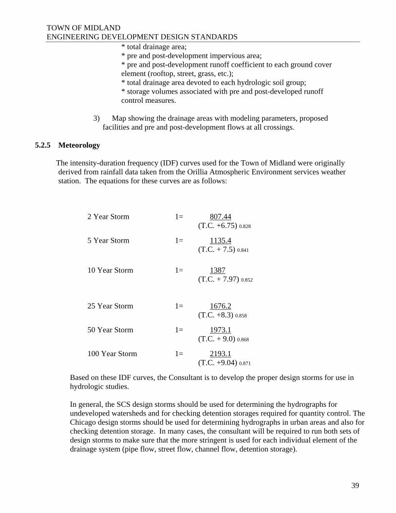
TOWN OF MIDLAND ENGINEERING DEVELOPMENT DESIGN STANDARDS
39
* total drainage area; * pre and post-development impervious area;
* pre and post-development runoff coefficient to each ground cover element (rooftop, street, grass, etc.);
* total drainage area devoted to each hydrologic soil group; * storage volumes associated with pre and post-developed runoff
control measures.
3) Map showing the drainage areas with modeling parameters, proposed facilities and pre and post-development flows at all crossings.
5.2.5 Meteorology
The intensity-duration frequency (IDF) curves used for the Town of Midland were originally derived from rainfall data taken from the Orillia Atmospheric Environment services weather station. The equations for these curves are as follows: 2 Year Storm 1= 807.44 (T.C. +6.75) 0.828
5 Year Storm 1= 1135.4 (T.C. + 7.5) 0.841
10 Year Storm 1= 1387 (T.C. + 7.97) 0.852
25 Year Storm 1= 1676.2 (T.C. +8.3) 0.858
50 Year Storm 1= 1973.1 (T.C. + 9.0) 0.868
100 Year Storm 1= 2193.1 (T.C. +9.04) 0.871
Based on these IDF curves, the Consultant is to develop the proper design storms for use in hydrologic studies.
In general, the SCS design storms should be used for determining the hydrographs for undeveloped watersheds and for checking detention storages required for quantity control. The Chicago design storms should be used for determining hydrographs in urban areas and also for checking detention storage. In many cases, the consultant will be required to run both sets of design storms to make sure that the more stringent is used for each individual element of the drainage system (pipe flow, street flow, channel flow, detention storage).
TOWN OF MIDLAND ENGINEERING DEVELOPMENT DESIGN STANDARDS
40
The time step for discretization of the designed storm can vary according to the size of the sub-watershed, but must not exceed the estimated time of concentration. The maximum rainfall intensity should be compatible with that of real storms on record.
5.3 SEWER DESIGN
5.3.1 Hydraulic Design Sewers shall be a minimum of 300 millimetres in diameter. Mannings Formula shall be used to calculate required pipe sizes. The roughness coefficient
for smooth bore pipes shall be 0.013. The minimum velocity shall be obtained by selecting a slope to ensure that cleansing
velocities occur once in two years on the average. Generally 0.75 metres per second for the 5 year return storm design flows may be used.
The first leg shall have a minimum of 1.00%. All other legs shall have a minimum grade of
0.50%. The normal maximum velocity shall be 5.00 metres per second at full flow for sewers and
1.50 metres per second for channels. Energy dissipaters at outlets will be designed to reduce velocities to 1.00 metre per second or less.
A sufficient drop shall be provided across each manhole to offset any hydraulic losses, the
obverts of inlet pipes shall not be lower than obverts of outlet pipes, and drop structures shall be used only when drops of more than 0.9 metres are necessary. Calculations for hydraulic losses shall be included with storm design information.
The minimum drop across manholes shall be 30 mm for straight runs, 75 mm for 0 degrees to
45 degree deflections and 150 mm for 45 degree and 90 degree deflections. Except for special cases, the downstream pipe diameter shall always be greater than or equal
to the upstream pipe diameter.
5.3.2 Run-off Calculations Flow Calculation Rainfall equations or curves and design storm hydrographs must be approved by the Director
of Public Works. When the Rational Method is used, an initial inlet time of 15 minutes shall be used except
where the zoning requires the use of a coefficient of 0.6 m or higher in which case a 10 minute inlet time shall be used.

TOWN OF MIDLAND ENGINEERING DEVELOPMENT DESIGN STANDARDS
41
Run-off coefficients are to be determined from the most recent MOE Guidelines. A minimum
run-off coefficient of 0.55 is to be used for undeveloped upstream area where future residential development is expected and 0.75, where future industrial, high-density residential or commercial development is expected.
Run-off coefficients for the Rational Method shall be as follows: Lawns: Sandy soil, flat, 2% 0.05-0.10 Sandy soil, average, 2-7% 0.10-0.15 Sandy soil, steep, 7% 0.15-0.20 Heavy soil, flat, 2% 0.13-0.17 Heavy soil, average, 2-7% 0.18-0.22 Heavy soil, steep, 7% 0.25-0.35 Business: Downtown Areas 0.70-0.95 Neighborhood Areas 0.50-0.70
Residential: Single-Family Areas 0.30-0.50 Multi Units, Detached 0.40-0.60 Multi Units, Attached 0.60-0.75 Suburban 0.25-0.40
Apartment Dwelling Areas 0.50-0.70 Industrial: Light Areas 0.50-0.80 Heavy Areas 0.60-0.90 Parks, Cemeteries 0.10-0.25 Playgrounds 0.20-0.35 Railroad Yard Areas 0.20-0.40 Unimproved Areas 0.10-0.30 Streets: Asphalt 0.70-0.95 Concrete 0.80-0.95 Brick 0.70-0.85 Drives and Walks 0.75-0.85 Roofs 0.75-0.95
TOWN OF MIDLAND ENGINEERING DEVELOPMENT DESIGN STANDARDS
42
Storm sewers shall be designed to drain all lands based on the Rational Method. The Rational Method calculations must be checked using a model approved by the Town Engineer where the drainage area is greater than10 hectares. The larger of the flows is to be used in the design of the sewer system unless approved otherwise.
Q= 0.0028 C I A where: Q = Flow in cubic metres per second A = Area in Hectares C = Run-off coefficient I = Intensity in mm/hr
5.3.3 Intensity of Rainfall The intensity of rainfall is to be determined from the Intensity-Duration-Frequency values
from the Atmospheric Environment Services Orillia Station.
5.3.4 Time of Concentration The minimum initial time of concentration is to be 15 minutes.
5.3.5 Pre-Development
To calculate the initial time of concentration (tic) for upstream, undeveloped lands, the
following formula may be used: Bransby Williams, HYMO/OTTHYMO, SCS Upland Method, etc. The most appropriate method will be determined at the discretion of the Town.
5.3.6 Post-Development
To calculate the initial external time of concentration (tc) for external lands that are scheduled
for future development, a straight line is to be drawn from the furthest point within the watershed to the proposed inlet. The top 50 metres shall have an initial tc of 10 minutes and the remainder shall have tc assuming the velocity in the sewer is 2m/s. The summation of the two tc’s will give the future external time of concentration.
If the upstream area has adequate storm sewers, channels, or culverts, the velocity of the flow through these sewers, channels, or culverts shall supersede the 2m/s calculation.
5.3.7 Drainage Area
Drainage systems must be designed to accommodate all upstream drainage areas considering
interim and ultimate conditions.
5.3.8 Sewer Material Pipes for main sewers shall be concrete or PVC DR35 with a minimum diameter of 300 mm
and shall conform to CSA Standard A257.1 with a minimum strength of 65D Class III or as required by depth.
TOWN OF MIDLAND ENGINEERING DEVELOPMENT DESIGN STANDARDS
43
Pipe for catchbasin leads shall be concrete with a minimum strength of E.S. or PVC DR28 rubber gasket type joints with a diameter of 250 mm for singles and 300 mm for doubles.
Sewers shall be constructed with bedding as per OPSD 802.03, Class B-1, Granular “A”
unless otherwise directed by the Town Engineer.
Catchbasin frames and grates shall be as per OPSD and shall be as manufactured by McCoy (or approved equivalent).
5.4 SYSTEM LAYOUT
Roof leaders are to be discharged to the ground surface to splash blocks and flows are to be
directed away from the building in such a way as to prevent ponding or seepage into weeping tile. Where flat roofs are used, as in commercial or industrial sites, detention roof hoppers requiring smaller or fewer roof leaders cannot be used as part of the stormwater management design.
Weeper tiles are not to be directly connected to the storm sewer system unless permission is
received from the Director of Public Works. All other connections to the storm sewers shall be made as approved by the Director of Public
Works.
Storm sewers shall generally be located as per the standard detail drawing for storm sewer. At bends in the road allowance the storm sewer shall follow along the same side.
When storm sewers or open drainage channels are located on easements the easement width
shall be 4.0 minimum. This minimum must be increased where the depth or diameter of service dictates greater working room.
A minimum depth of 1.5 metres to the spring line from the finished road or ground surface
elevation, or a sufficient depth for any foundation drains or other connections shall be provided. Fill beneath sewers is to be compacted to 98% SPD.
Minimum clearances between services shall be provided in accordance with MOE guidelines.
Manholes shall be placed at the end of each sewer, at changes in size and material and at
changes in grade and alignment. Curved or properly deflected sewer lines may be allowed with the approval of the Director of Public Works.
Manhole tops are to be set to base course asphalt grade and then adjusted to final grade, when
top lift of asphalt is placed.
The maximum spacing between manholes shall generally be according to the following: Metres - 300 to 750 mm dia. 110

TOWN OF MIDLAND ENGINEERING DEVELOPMENT DESIGN STANDARDS
44
- 825 to 1200 mm 125 - Over 1200 dia. 155 Deflection of storm sewers at a manhole shall not be more than 90 degrees. Drop manholes shall be provided for all sewer junctions having an elevation difference in
excess of 0.9 metres that cannot be eliminated by changing sewer grades. Where manholes are located in areas to be flooded by the major storm design and surcharged
sewer design is not used, manhole covers shall be of the sealed variety. Where manholes are located where the surcharged sewer design hydraulic grade line is higher
than the rim elevation, manhole covers shall be of the bolted variety. In all other areas standard manhole covers shall be used.
Catchbasins are to be located at all low points, upstream of pedestrian crossings and not within
1.0 m of curb depressions. Preferable, catchbasins where required will be adjacent to lot lines. The maximum allowable spacing shall be 80 m where catchbasins are not used as inlet
controls. Where catchbasins are designed for inlet controls, spacing shall be determined by design.
Catchbasin leads shall be minimum 250 mm at a minimum grade of 0.7% for single
catchbasins and 300 mm at a minimum grade of 0.7% for double catchbasins. Leads shall connect to manholes where possible. Where catchbasins are designed for inlet controls, lead sizes down to 150 mm for singles or doubles can be used where such sizes will limit flows to the gravity capacity of the sewer system.
Rear lot catchbasins shall be located 1.5 m from the back lot line and 1.0 m from the side lot
line and the catchbasin and lead shall be located in a minimum 4.0 m wide easement centered on the lot line.
5.4.1 Storm Sewer Requirements
a. Trunk Sewer System
A trunk sewer system shall be defined as part of a drainage system that drains an area of 100
ha of land or greater. Trunk storm sewer systems shall be designed to accommodate a 25 year storm.
b. Pipe Capacities
Manning’s formula shall be used in determining the capacity of all storm sewers. The
capacity of the sewer shall be determined on the basis of the pipe flowing full. The value of the roughness coefficient ‘n’ used in the Manning’s formula shall be as follows: - concrete Pipe 0.013 - concrete box culverts 0.013 - corrugated Metal 68 x 13 mm corrugations 0.024

TOWN OF MIDLAND ENGINEERING DEVELOPMENT DESIGN STANDARDS
45
- corrugated Metal 25% paved invert 0.021 - PVC Pipe 0.013
c. Flow Velocities (Flowing full) For circular pipes the minimum acceptable velocity is 0.75 m/s and the maximum acceptable
velocity is 4.0 m/s d. Minimum Sizes
The minimum size for an on street storm sewer shall be 300 mm.
e. Depth of Storm Sewers
Storm sewers shall have a minimum frost cover of 1.5 m. Where the minimum cover is not
possible the Engineer shall provide a design solution with consideration for additional loading due to frost.
f. Location
The storm sewers shall be located as shown on the standard Town of Midland road cross
section drawings. A minimum clearance of 500 mm shall be provided between the obvert of the sanitary sewer
and the invert of the storm sewer. The sanitary sewer connections are required to go under the storm sewer.
g. Radius Pipes
Radius pipe shall be allowed for storm sewers 975 mm in diameter and larger provided that a
maintenance hole is located at the beginning or at the end of the radial section. The minimum center line radius allowable shall be in accordance with the minimum radii table as provided by the manufacturers.
h. Limits of Construction
Sewers shall be terminated with a maintenance hole at the subdivision limits when external
drainage areas are considered in the design. The design of the terminal maintenance holes must allow for the future extension of the sewer.
i. Sewer Alignment
Storm sewers shall be laid in a straight line between maintenance holes unless radius pipe has
been designed. Joint burial (common trenching) with sanitary sewers will be considered when supported by the recommendations of a soils report prepared by a qualified Geotechnical Engineering Consultant.

TOWN OF MIDLAND ENGINEERING DEVELOPMENT DESIGN STANDARDS
46
j. Changes in Pipe Size No decrease of pipe size from a larger upstream to a smaller size downstream will be allowed
regardless of the increase in grade.
k. Standard Easement Requirements The minimum width of easements for storm sewers shall be in accordance with the following
guidelines. Size of Pipe Depth of Invert Minimum Width of Easement 250 to 375mm 3.0 m maximum 4.0 m 450 to 675mm 3.0 m maximum 4.5 m 750 to 1500mm 3.0 m maximum 6.0 m 1650mm and up 4.0 m maximum 4.0 plus 3 times O.D. of Pipe For easements containing more than one pipe or underground service the minimum width will
be based on the above chart for the maximum pipe size plus 3.0 m. Regardless of the preceding, all situations will be reviewed and judged on individual cases at
the discretion of the Town. In areas where it is difficult to control the infiltration of ground water into the sewer trenches a
clear stone may be used provided it is completely wrapped in a suitable geotextile, selected and installed in accordance with the manufacturer’s requirement.
The width of trench at the top of the pipe must be carefully controlled to ensure that the
maximum trench width is not exceeded unless additional bedding or higher strength pipe is utilized.
l. Testing and Acceptance
All storm works shall be thoroughly flushed and/or cleaned of debris and all pipes shall have a
CCTV inspection as per OPSS 409 as part of the final acceptance inspections.
5.4.2 Maintenance Hole Requirements Maintenance holes may be either precast or poured in place and shall be designed and
constructed in accordance with the most recent OPSS and OPSD. Where the standard drawings are not applicable, the maintenance holes shall be individually designed and detailed.
a. Location and Spacing
Maintenance holes shall be located at each change in alignment, grade or pipe material, at all
pipe junctions, at the beginning or end of radius pipe sections and at intervals along the pipe to permit entry from maintenance to the sewer.

TOWN OF MIDLAND ENGINEERING DEVELOPMENT DESIGN STANDARDS
47
Maximum spacing of maintenance holes shall be 300 to 750 mm in diameters. for 110 metres
and 825 to 1200 mm in diameter for 125 metres and anything over 1200 diameters for 155 metres.
The change in direction of flow in any maintenance hole shall not be more than 90 degrees.
Maintenance holes shall be located, wherever possible, a minimum of 1.5 m away from the face of curb and/or any other service.
b. Head Losses and Drops
Suitable drops shall be provided across maintenance holes to compensate for the loss in
energy due to the change in flow velocity and for the difference in the depth of flow in the sewers.
In order to reduce the amount of drop required, the designer shall, wherever possible, restrict
the change in velocity between the inlet and outlet pipes to 0.6 m/s. Hydraulic calculations shall be submitted for junction and transition maintenance holes on
sewers where the outlet is 1050 mm diameter of greater. In addition, hydraulic calculations may be required for maintenance holes where the outlet pipe is less than 1050 mm diameter if, in the opinion of the Town, there is insufficient invert drop provided across any maintenance hole.
Regardless of the invert drop across a maintenance hole as required by calculations, the obvert
of the outlet pipe shall not be higher than the obvert of the inlet pipe at any maintenance hole location.
The minimum drops across maintenance holes shall be as follows: Change of Direction Minimum Drop (mm) 0 degrees 30 1 degree to 45 degree 50 45 degree to 90 degree 80
5.4.3 Catchbasin Requirements Catchbasins must be precast and shall be designed and constructed in accordance with the
most recent OPSD and OPSS requirements. a. Location and Spacing Catchbasins shall be selected, located and spaced in accordance with the conditions of design.
The design of the catchbasin location and type shall take into consideration the lot areas, the lot grades, pavement widths, road grades and intersection locations.

TOWN OF MIDLAND ENGINEERING DEVELOPMENT DESIGN STANDARDS
48
Maximum spacing for catchbasins including cul-de-sac gutters shall be as follows:
- Road grade 0.5% to 0.75% - 70 m - Road grade 0.76% to 3.0% - 95 m - Road grade 3.1% to 4.5% - 90 m - Road grade greater than 4.6% - 75 m
Catchbasins shall be generally located upstream of pedestrian crossings. Catchbasins shall not
be located in driveway curb depressions. b. Catchbasins Types Typical details for single, double, and rear lot type catchbasins are shown in the OPSD. Any special catchbasins and inlet structures must be fully designed and detailed by the
Engineer for approval by the Town. Double catchbasins are to be installed at the low point of any road.
c. Catchbasins Leads For single catchbasins the minimum size of connection shall be 250 mm and the minimum
grade shall be 2.0%. For double catchbasins, including rear lot catchbasins, the minimum size of connection shall be 300 mm and the minimum grade shall be 2.0%.
Doubles with back arches to be provided in sags. In general, catchbasins located in close proximity to a downstream maintenance hole shall
have their leads connected to the maintenance hole. Long catchbasin connections (in excess of 20 m) shall be connected to a maintenance hole.
d. Frame and Grate The frame and cover for catchbasins in roadway or walkway areas shall be as detailed in the
OPSD 400.02, with type B open cover. Catchbasins located within the traveled portion of a roadway shall have the frame elevation set flush with the surface of the base course asphalt. The adjustment and setting of the frame and cover shall be completed in accordance with the details provided in the OPSD 704.010. Catchbasins located in grassed areas shall have the Birdcage Grate per 400.120.
5.4.4 Roof Leaders, Foundation Drains and Storm Connections
Roof leaders shall not be connected directly to the Town sewer systems. Leaders shall
discharge to concrete splash pads in landscaped areas and directed to side yard swales. Foundation Drains
TOWN OF MIDLAND ENGINEERING DEVELOPMENT DESIGN STANDARDS
49
It is the Town policy that foundation drains shall not be connected directly to the Town sewer
systems. A sump pump system shall discharge to a concrete splash pad in a landscaped area and with the water directed to side yard swales. The geotechnical report shall consider the ground water table elevation and recommend minimum basement elevations. Foundation drain discharge water that becomes a nuisance shall be corrected.
5.4.5 Channel, Culvert and Overland Flow For channel, culvert, bridge and/or erosion control projects the proponent is responsible for
obtaining all necessary approvals from the governing agencies, such as the MNR, DFO and/or MOE.
Culverts and Bridges Road Classification Design Flood Frequency Arterial 1:100 Year to Regional Collector 1:50 Year Urban Local 1:25 Year Rural Local 1:25 Year Temporary Detour 1:10 Year Driveway 1:5 Year
Bridges and other major drainage structures shall require special designs as determined by the
Town. Hydraulic calculations will be required. The frequency and magnitude of flooding or erosion shall not be increased on upstream or
downstream properties.
5.5 OPEN CHANNELS The proposed criteria for an open channel design shall be submitted to the Town for approval
prior to the actual design being undertaken. Open channels shall be defined as major system overland flow channels, minor system outfall channels or natural channels. Major system overland flow channel designs may be required to accommodate the Regional storm or the 100-year storm for new development.
“Natural” channel design criteria will be determined on a site by site basis. The following
guidelines must be considered: Open Channels Minimum Velocity Maximum Velocity Grass lined – Natural 0.7 m/s 1.5 m/s Grass lined – Maintained 0.7 m/s 1.5 m/s Gabion lined 0.7 m/s 2.5 m/s Concrete lined 0.7 m/s 4.0 m/s 5.6 OPEN DITCHES

TOWN OF MIDLAND ENGINEERING DEVELOPMENT DESIGN STANDARDS
50
In industrial developments, rural developments or developments within the Little Lake Watershed open ditches may be permitted by the Town. Ditches shall be constructed below the sub-grade of the roadway a maximum of 0.5 m and a minimum of 0.15 m.
The minimum ditch grade shall be 0.5% and the maximum 6%. In exceptional cases and
where ditches are on easements off the Road Allowance, ditches with grades greater than 6% may be allowed by the Director of Public Works but these shall be suitably protected against erosion to the satisfaction of the Engineers.
The minimum ditch protection on all ditches shall be 150 m of topsoil and staked sod on the
side slopes and bottom of the ditch regardless of the ditch gradient. Normal ditch to ditch road culverts shall be installed where required as follows: - Minimum Length; as required from centre of ditch to centre of ditch; - Minimum size; 500 mm diameter for road crossing, 400 mm driveway;
- Material; standard galvanized corrugated pipe, spirally corrugated pipe will not be permitted;
- Gauge; as recommended by manufacturer for H20 Highway loading, minimum 2.0 mm
thickness; - Cover; 300 mm minimum for road crossings; - Bedding; culverts shall be bedded and backfilled with granular material in accordance with
OPSS. Open channels are to be designed as follows: - For the Regional Storm where the upstream watershed area exceeds 1 square kilometer; - For a minimum 25 year return frequency storm with protection form erosion damage for
larger storms if required by the Town Engineer; - To maintain the natural storage characteristics of the watercourse; - To maintain a natural appearance as far as possible;
Outfall structures to existing channels or watercourses shall be designed to minimize potential erosion or damage in the vicinity of the outfall from maximum design flows.
5.7 Watercourse Erosion and Bank Stability Where erosion or bank instability is already evident in an area to be developed or re-
developed, the Town of Midland requires that the situation be stabilized by appropriate remedial measures. Where development will cause significantly increased downstream

TOWN OF MIDLAND ENGINEERING DEVELOPMENT DESIGN STANDARDS
51
erosion, the Town also requires the Developer to mitigate further damage by appropriate remedial measures.
Where designing remedial erosion or bank stabilization works, preservation of the watercourse
dynamics and natural valley aesthetics must be secondary only to achieving a sound technical solution. A normal bank flow channel has a capacity of about the 1:2 year flood. Protection to this level will be adequate provided care is taken to prevent any damage by higher floods and provide that the channel bank is not coincident with a higher valley bank. In this latter case, it may be necessary to protect the bank to a level as high as the 1:100 year flood or even the flood resulting from the Regional Storm.
The proposed criteria for an erosion or bank stability design shall be submitted to the Town
for approval prior to the actual design being undertaken. 5.8 Overland Flow Routes An overland flow route continuous to the nearest major channel must be established through
all areas and shall be contained within either the road right-of-way or by easements. The depths of flooding permitted on streets and at intersections during the 1:100 year storm
are as follows: * No building shall be inundated at the ground line, unless the building has been Flood proofed; * For all classes of roads, the depth of water at the gutter shall not exceed 0.3 m. Flow across road intersections shall not be permitted for minor storms (generally 1:10 year).
To meet the criteria for major storm run-off, low points in roads must have adequate provision for the safe overland flow.
5.9 Inlet/Outlet Structures Inlet and outlet structures shall be fully detailed on the engineering drawings. The details
provided shall include the existing topography, proposed grading and the works necessary to protect against erosion.
Adequate means such as gabion basket, rip-rap or concrete shall be provided at all inlets to
protect against erosion and to channel the flow to the inlet structure and at all outlets to prevent erosion. The extent of the erosion protection shall be indicated on the engineering drawings and shall be dependent upon the velocity of the flow in the storm sewer outlet, the soil conditions, the flow in the existing watercourse and site conditions.
The inlets and outlets must be protected to prevent unauthorized access and debris
accumulation. Outfall structures to existing channels or watercourses shall be designed to minimize potential
erosion or damage in the vicinity of the outfall from maximum design flows.

TOWN OF MIDLAND ENGINEERING DEVELOPMENT DESIGN STANDARDS
52
The obvert of the outlet pipe is to be above the 25 year flood elevation of the receiving channel.
5.10 Maintenance The Developer shall maintain the complete storm sewer system, including routine cleaning for
the duration of the maintenance period. The storm sewers shall be maintained until assumption of all municipal services in the subdivision.
Channel works (including headwall structures) shall be maintained until assumption of the
subdivision.
6.0 SANITARY DRAINAGE SYSTEM 6.1 GENERAL 6.1.1 Required System The sanitary sewer system is to be designed to carry domestic, commercial and industrial
sewage for each area or development under consideration. Flow is to be by gravity and pumping will be considered only where other alternatives are not possible and only with the approval of the Director of Public Works.
If a pumping station is approved by the Town it shall be designed in accordance with the
MOE guidelines with standby power, separate dry well and Town of Midland Standard SCADA Controls all to the satisfaction of the Director of Public Works.
6.1.2 Service Area The system shall be designed to service all areas within the subdivision to their maximum
future development in accordance with the Town’s Official Plan. Allowance shall be made for inflows from the appropriate adjacent subdivisions or areas and shall meet with the approval of the Director of Public Works. Discharges of the system are to be into appropriate sewers and are to be approved by the Town Engineer. The exact location for connecting to sewers in adjacent subdivisions or areas shall be as approved by the Director of Public Works.
6.1.3 Drains

TOWN OF MIDLAND ENGINEERING DEVELOPMENT DESIGN STANDARDS
53
All floor drains are to be connected to the sanitary sewer. Foundation drains, sump pumps and roof water leaders are not to be connected to the sanitary sewer.
6.1.4 Design Flows The sewers are to be sized for maximum design flows plus an allowance for infiltration.
Minimum velocities and slopes are to be determined for maximum design flows without infiltration.
The average daily domestic flow is to be taken as 450 L/day capita. Occupancy shall be taken
as 3.0 persons per Single Family Dwelling, 2.5 persons per Townhouse Unit and 2.0 persons per Apartment Unit.
Other flow rates shall be as follows: Commercial - 2.5 L/day/m2 of floor area School - 100.0 L/day/student Light Industrial - 35.0 m3/day/Ha Maximum design flows are to be determined using average daily flows and the Harmon
Peaking Factor. A wet weather infiltration rate of 20,000 litres/hectare/day = 0.23 litres per second per gross
hectare is to be used. To satisfy self-cleaning requirements in sanitary sewers, assume dry weather infiltration reduces to zero for several days during dry months.
6.2 SANITARY SEWERS 6.2.1 Sewer Design a. Hydraulic Design Mannings formula shall be used for determining the capacity of the sewer. A roughness
coefficient of n=0.013 shall be used for all types of pipe. The minimum size of sewers shall be a diameter of 200 mm. The minimum velocity for sewers operating partially full shall result in self-cleaning
equivalent to that produced by flow in sewer operating full at a velocity of 0.6 m/s. The maximum velocity shall be 3.0 m/s at full flow. A sufficient drop shall be provided across each manhole to offset any hydraulic losses, the
obverts of inlet pipes shall not be lower than obverts of outlet pipes, and drop structures shall be used only when drops of more than 0.9 metres are necessary.

TOWN OF MIDLAND ENGINEERING DEVELOPMENT DESIGN STANDARDS
54
The minimum drop across manholes shall be 30 mm for straight runs, 75 mm for 0 degrees to 45 degrees deflections and 150 mm for 45 degrees and 90 degrees deflections.
Except for special cases, the downstream pipe diameter shall always be greater than or equal to the upstream pipe diameter.
The first leg shall have a minimum grade of 1.00%. All other legs shall have a minimum
grade of 0.50%. 6.2.2 System Layout When sanitary sewers are located in easements the easement width shall be 4.0 m minimum.
This minimum must in increased where the depth of diameter of service dictates greater working room.
A minimum cover of 2.8 metres below the centre line road elevation and sufficient depth for
basement floor drains and frost cover shall be provided. Where sewers are located within an easement a minimum frost cover of 1.9 m may be used provided such sewers cross below watermains. Fill beneath sewers is to be compacted to 98% SPD.
Minimum clearances between services shall be provided in accordance with MOE guidelines. Manholes shall be placed at the end of each line, at changes in size and material, and at abrupt
changes in grade and alignment. Curved or properly deflected sewer lines are allowed with approval of the Director of Public Works.
Manhole types and sizes shall be in accordance with MOE guidelines. All manholes are to be
benched to the satisfaction of the Director of Public Works. No sanitary sewer manhole may be constructed closer than 1.5 m to the curb. Manhole tops are to be set to base course asphalt grade and then adjusted to final grade, when
top lift of asphalt is placed. The maximum spacing between manholes shall be 110 m. Drop manholes shall be provided for all sewer junctions having an elevation difference in
excess of 0.9 metres that cannot be eliminated by changing sewer grades. Where manholes are located in areas to be flooded by the major design storm, manhole covers
shall be of the sealed variety and the manhole is to be suitably vented. Single sanitary laterals for residential and industrial use, shall generally be located at the
centre line of the lot with the water service located 2.5 m to the north or west of the sanitary lateral. Connections for commercial, institutional or multiple use will be considered on an individual basis if similar locations cannot be used. Non-standard locations must be detailed on plan and profile and lot grading plans.

TOWN OF MIDLAND ENGINEERING DEVELOPMENT DESIGN STANDARDS
55
Service connections shall be located at a minimum depth of 2.0 m at the property line, and sufficient depth for basement floor drains and frost cover. Service connections should cross under any watermains. Fill beneath services is to be compacted to 98% SPD.
Sanitary connections to manholes will be allowed only if the invert is connected no higher
than the obvert of the outlet pipe in the manhole and property benched. 6.2.3 Materials For sizes of 200 to 375 mm diameter pipe shall be PVC SDR 35, rubber gasket type joints and
shall conform to CSA (B-182.2, 3, 4). Single residential sanitary connections shall be provided, minimum 125 mm diameter with
125 x 100 Crowle test fitting plugged and braced at the property line. The minimum slope shall be 2%. Connections for commercial, industrial and institutional will be considered separately and generally be 150 mm minimum diameter with a inspection maintenance hole of property line with only one lateral entering the structure.
Pipe shall be PVC SDR 28, rubber gasket type joints and shall conform to CSA (B- 182.2, 3,
4). 6.2.4 Testing of Sewers and Manholes The complete sewer system including service connections to the property line and manholes
shall be tested in accordance with OPS. Approximately one year prior to the expiration of the maintenance period the complete system shall be inspected by an approved video camera testing company and the Director of Public Works shall be provided with a copy of the appropriate data prior to final approval. Any sections of sewer or service connections which fail to meet the requirements shall be repaired or replaced at the direction of the Director of Public Works. Only chemical pressure grouting repair techniques will be considered acceptable.
6.2.5 Service Connections - one connection per development lot - see OPSD 1006.010 and 1006.020
6.2.6 Maintenance The Developer shall maintain the complete sanitary sewer system including routine flushing
for the duration of the maintenance period. The sanitary sewer will not be released from the maintenance period until assumption of the subdivision.
6.2.7 Maintenance Holes

TOWN OF MIDLAND ENGINEERING DEVELOPMENT DESIGN STANDARDS
56
- to avoid undue impact loads, wherever possible maintenance holes and utility vaults or valves shall be located away from the normal wheel track
- see OPSD Drawings 701.010, 701.011, 701.012, and 701.013 - drops as per OPSD Drawings 1003.010, 1003.020 6.2.8 Limits of Construction Sewers shall be terminated with a maintenance hole at the subdivision limits when external
drainage areas are considered in the design. The design of the terminal maintenance holes must allow for the future extension of the sewer.
Sanitary Sewers - Ministry of the Environment and Energy Guideline for the Design and Sanitary Sewage Works - minimum pipe diameter to be no less than 200 mm
7.0 SIDEWALKS AND WALKWAYS 7.1 Sidewalks A 1.5 m wide concrete sidewalk shall be placed in locations approved by the Town at
minimum on one side of each roadway. All sidewalks shall be constructed on a properly constructed foundation of 150 mm minimum
depth of Granular “A” and be paved with concrete full width. Thickness to be 130 mm in general, 150 mm across residential driveways and 200 mm across commercial and industrial entrances. All concrete materials and work shall conform to O.P.S. Specifications.
- 0.5% minimum to 7% maximum grade with a minimum cross fall of 2% - no steps
allowed - OPSD 310.010, 310.030 - Concrete strength min. 30 Mpa 28 day test - Sidewalk to be continuous through all driveways and entrances 7.2 Walkways Walkways shall be minimum of 4.57m wide and placed in locations approved by the Town.
TOWN OF MIDLAND ENGINEERING DEVELOPMENT DESIGN STANDARDS
57
All walkways shall be constructed on a properly constructed foundation of 150 mm minimum depth of Granular Base Course Class “A” and paved with concrete full width. Thickness requirements same as sidewalks. All concrete materials and work shall conform to O.P.S.S.
Removable metal bollards, placed at 1.0 m spacing, shall be placed at each end to restrict
vehicular traffic. - see Town of Midland Standard # SD 500.1 7.3 Pedestrian Ways 7.3.1 Trailways The Developer may be required to design and construct a trail system, walkways and linkages
to existing trail systems. Trail developments will be implemented according to Town standards. All trail and walkway developments shall be shown on the landscape plans.
The minimum standard for the multi-use urban trail shall be: * 3.0 m width, of 150 mm concrete; * 30 Mpa with 6-8% entrained air; * 6x6x6Ga welded wire mesh; * 200 mm granular A base compacted to 100% SPDD; * broom finish with tooled edges and control joints. 7.3.2 Intersections - for design criteria see Ministry of Transportation Policies and Guidelines 7.3.3 Boulevards - sodded between road and property line – 2% minimum to 7% maximum slope - concrete between intersecting sidewalks and curb at intersections 8.0 STREET LIGHTING Street lights on 9.1 m concrete poles shall be installed throughout the subdivision and may be
required on arterial or Provincial roadways bordering the development if deemed necessary by the Town. The type and layout of the street lighting must be to the satisfaction of the Midland PUC and Director of Public Works.
The maximum allowable spacing shall be 45 m unless specifically approved by the Director of
Public Works. Poles must be installed on projections of lot lines. Street lighting units shall normally be Full Cut-off Dark Sky compliant LED Edge slim low
profile fixtures, photocell controlled with no less than 6320 delivered lumens (Generation B - Four Light bar assembly), silver coloured, as manufactured by Ruud/Beta LED Lighting (Ruud/Beta Part No. X–SL–O–H–08–D–U–S–H–R), or approved equivalent. In cases when the Developer wishes to install street lights having a particular style, approval for the use of

TOWN OF MIDLAND ENGINEERING DEVELOPMENT DESIGN STANDARDS
58
such street light units shall be obtained from the Town and from Midland PUC but in any case they must be LED light units.
The wattage of lights shall be as follows: - Arterial & Collector - 150 W HPS with 250 W HPS Roads at Intersections - Local Roads - 100 W HPS with 150 W HPS at Intersections - Industrial/Commercial - 150 W HPS with 250 W HPS at Intersections 8.1 Lighting Levels and Uniformity Ratio Street lighting shall be supplied and installed on all streets and pedestrian walkways in the
subdivision. Road Classification (ROW/Pavement) Illumination Level / Uniformity Ratio Residential 20m/8.5m 2 Lux/6:1 Urban Collector 26m/14.5m 6 Lux/3:1 Minor Arterial, Ind. Collector 30m/16.0m 9 Lux/3:1 Walkways 2 Lux/6:1 Estate Residential development lighting shall be based on an average pole spacing of 100
meters. - pole to be stress-crete poles or Powco Steel octagonal hot-dipped galvanized Series 1100
poles or equivalent - any use of decorative style luminaire fixtures and/or special poles to be pre-approved by
the Engineering Department - see OPSD drawings 2100.01, 2101.01, 2103.04, 2210.01, 2210.02, 2225.01, 2250.01,
2410.01 and 2420.01

TOWN OF MIDLAND ENGINEERING DEVELOPMENT DESIGN STANDARDS
59

TOWN OF MIDLAND ENGINEERING DEVELOPMENT DESIGN STANDARDS
60

TOWN OF MIDLAND ENGINEERING DEVELOPMENT DESIGN STANDARDS
61
8.2 Approval and Construction Approval of plans for streetlighting must be obtained from the Town. The Developer must
guarantee and maintain the lighting until final acceptance of the development. The Town, upon energization of the streetlighting, will pay energy charges.
9.0 GRADING AND LANDSCAPING 9.1 GENERAL Lot grading shall conform to the following specifications. Lot Grading Criteria The lot grading shall provide for the following: - rear to front lot grading is preferred and a maximum of three rear lots shall outlet between
any two lots; - rear lot catchbasins shall be eliminated wherever possible; - maximum number of lots drained by a rear lot CB shall be 5; - where rear lot catchbasins are used all structures shall be protected from flooding if the inlet
is blocked or surcharged by a major storm event; - maximum ponding depth for drainage swales is 0.35 m. - where several lots drain through a swale to a rear lot catchbasin on private property, an
easement shall be provided for the CB and lead; - minimum slope for swales shall be 2.0%; - a minimum of 5.0 meter of the rear yard shall be graded at 2% -5% slope; - each lot shall have at least one side yard with a maximum slope of 2% for 1.0 m continuous width from front to rear yard; - maximum slope between houses shall be 4:1; - driveways shall have minimum 2% and maximum 7% slope; - grade around houses shall be a minimum of 2% away from houses from point 200 mm
below top of foundation wall or as required by OBC. 9.2 OVERALL GRADING PLAN An overall grading plan, which may incorporate the information required for the drainage
plan, shall be submitted to and approved by the Director of Public Works. The plan shall show existing elevations for each lot corner along with contours plotted at 0.5
m intervals. Contours should be extended 30.0 m outside of the development area. Proposed elevations for the street centerline at 20 m intervals, lot corners, building lines, break
points in side yard swales and first floor of each house shall be shown. Minimum specified house grades shall be shown as per the standard detail drawings.
9.3 TREE PLANTING

TOWN OF MIDLAND ENGINEERING DEVELOPMENT DESIGN STANDARDS
62
O ne tree per lot shall be planted in a location stipulated or approved by the Town. A minimum separation of 3 m is required between the tree location and any service to the lot.
Each tree shall have a minimum height of 3.2 m and a diameter of 50 mm measured 0.3 m
above grade, and must be planted in accordance with good nursery practices. The trees selected may be any two or more varieties chosen from the following: Acre platanoides – Norway Maple including Crimson King and Schwedleri; Ginkgo biloba – staminate trees only; Moraine Locust; Quercus Borealis – Red Oak; Tilia cosdata – Little Leaf Linden. Other species and varieties may be planted subject to the written approval of the Town.
9.3.1 General Streetscape Standards The standard details and specifications found in this section govern planting and fence
construction along roads of all classifications. The streetscape design must conform to the Town of Midland Subdivision Design Guidelines.
9.3.2 Notes for Streetscape Submission Drawings The following notes pertaining to layout requirements are to be included on all streetscape
submission drawings: NOTE 1 Depicted on this plan are the species and the approximate location of street trees. Once
driveways, utilities and light standards have been installed, the exact location of street trees will be staked on site by the Landscape Architect and approved by the Town prior to planting.
NOTE 2 Minimum clearances for Street Trees (when trees are planted 1.5 m from the curb): - 2.0 m from water hydrants; - 2.0 m from driveways; - 2.0 m from neighbourhood mailboxes; - 3.0 m from hydro transformers; - 5.0 m from streetlight poles; - 15.0 m minimum from street line (street intersection as measured from back of curb) and behind the daylight triangle as per the Geometric Design Standards for Ontario
Highways; - 18.0 m from face of all warning signs. When the minimum distances noted above are not achievable, street trees may be planted in an
alternate location, 0.5 m from the property line (0.8 m behind the sidewalk) and adjacent to any fences. In cul-de-sac locations the street tree may be planted just inside the private property line. If a tree is planted in an alternate location, the distances marked with an asterisk must still be maintained.
NOTE 3

TOWN OF MIDLAND ENGINEERING DEVELOPMENT DESIGN STANDARDS
63
The tree pits and planting beds for all trees and shrubs located within 1 metre of underground utilities are to be hand dug.
NOTE 4 Minimum clearance for fences from fire hydrants is 1.0 m. NOTE 5 All plant material must conform to the Canadian Standards for Nursery Stock and must be
guaranteed for a minimum period of 24 months following acceptance of the work by the Town.
9.3.3 List of Details and Specifications The following standard details are to be provided in your submission 1) Deciduous Tree Planting 2) Coniferous Tree Planting 3) Shrub Planting 4) Tree Preservation Detail 5) Chain Link Fence 6) Wood Privacy Fence 7) Emergency Access and Walkway Gate 8) Removable Bollard 9) Multi-Use Urban Trail (Paved) 10) Multi-Use Rural Trail 11) Walking/Hiking Trail
9.3.4 Minor Road Street Trees Minor Roads should be planted with high branching deciduous trees (60 mm caliper
minimum). It is recommended that a variety of species be employed in groups. 9.3.5 Corner Lot Treatments Corner lots exposed to Minor Roads require special privacy measures that may include
fencing, tree planting or a combination of both to ensure a useable private amenity area 9.3.6 General Planting Considerations for Internal Streets The following list of planting design guidelines represents the general streetscape planting
objectives for the Town. Streetscape and buffer plans should meet the Town of Midland Subdivision Design Guidelines.

TOWN OF MIDLAND ENGINEERING DEVELOPMENT DESIGN STANDARDS
64
Tree Spacing – The recommended spacing is a minimum of one street tree planted every ten metres along all minor internal streets.
Lot configuration – The planting design must address the variations in lot configurations. The
recommended spacing suggests that most lots will receive at least one tree, although the shape and configuration of the property will be the final determinant of tree layout.
Utilities – The presence of utilities, mailbox clusters and the curb may interfere with the
preferred placement of street trees. The planting design must be flexible enough to accommodate on-site adjustments.
Horticultural accents – In locations where the subdivision layout and roadway design permits
horticultural accent plantings, the use of smaller flowering trees are shrubs encouraged in continuous mulched beds.
Walkway Easements – Walkway easements adjacent to side yards and rear yards shall be
fenced to discourage trespassing. Landscape Buffers – In locations where landscape screening is required along primary
roadways, the use of a wide variety of evergreen and deciduous trees and evergreen and deciduous shrubs is encouraged. The materials should be planted in naturalistic groupings in continuous mulched beds.
Boulevard Restoration – The boulevards along the Town’s road right-of-way must be sodded. 9.3.7 Standard and Guidelines for Naturalization Areas All disturbed natural open-space blocks, and lands adjacent to conservation areas, as well as
the lands surrounding stormwater management facilities are to be re-vegetated using naturalizing plant materials. The planting design must employ native plants using a variety of trees shrubs and ground covers to re-establish the local ecosystem. If the site had been previously disturbed, landscape restoration strategies must be employed to reinstate a naturalized landscape condition.
9.3.8 Notes for Naturalization Submission Drawings The following layout note is to be included on the submission drawings for all areas to be
naturalized: NOTE 1 All plantings and hard landscape features are to be staked out on site and approved by the
Landscape Architect and Town prior to installation. Any deviations from the approved landscape plans require prior Town approval.
9.4 SODDING AND SEEDING Each lot is to be entirely sodded over 150 mm of topsoil.

TOWN OF MIDLAND ENGINEERING DEVELOPMENT DESIGN STANDARDS
65
9.5 LOT DEVELOPMENT PLANS After approval of the overall grading plan and prior to the issuance of building permits, the
Consulting Engineer shall submit to the Director of Public Works for approval of 2 sets of the proposed lot development plan for those particular lots (or set of dwellings in the case of townhouse or multi unit dwellings) for which a building permit is desired. That submission would be accompanied by a letter which would express the Consulting Engineer’s approval. The requirements for the lot development plans and design criteria for lot grading and drainage are outlined in the Lot Grading Guidelines attached as Appendix “A”.
It is expected that the majority of proposed lot development plans would conform to the
general lot grading plan. All deviations which are certified by the Consulting Engineer and subsequently approved by the Town will require a revision to the overall lot grading plan.
9.6 FENCING Chain link fence, 1.5 m height, shall be installed along all walkways, open spaces, parks, steep
slopes, school, commercial and industrial properties and as required by the Town. The fence shall be installed as per OPSS and OPSD with top rail, knuckled top edge fasteners, knuckled bottom edge and No. 9 gauge wire mesh.
Privacy fence, as per Town Standard and sound attenuation fence shall be installed where
required. Fencing shall be in accordance with the most recent requirements and specifications of the
Town as shown on the standard drawings. Fencing is required: - along side yard flankage and/or rear yards backing onto roadways unless noise
attenuation barriers are required; - along public walkways (In accordance with Town Standard 900.00 and 915.00); - parks, ponds and open space blocks; - as designated by the Director of Public Works; - acoustic fencing per approved report. The minimum requirement for residential screen fencing is 1.8 m. 10.0 EROSION AND SEDIMENT CONTROL 10.1 General All erosion and sediment controls are temporary measures constructed prior to any other site
work, and shall be maintained until assumption of the subdivision. Prior to assumption of the subdivision all temporary measures shall be removed and any disturbed areas stabilized.

TOWN OF MIDLAND ENGINEERING DEVELOPMENT DESIGN STANDARDS
66
All erosion and sediment control measures shall be inspected by the Consultant once per week and after each rainfall of 1 cm or greater. Inspection reports shall be forwarded to the Town Engineering department within 5 days of inspection.
Erosion and sediment control measures shall be designed in accordance with Provincial
guidelines. 10.2 Catchbasin Sediment Control The requirement for catchbasin sediment control is as follows: - during construction, all catchbasins shall be provided with sediment control and this shall be
maintained until assumption; - catchbasins shall be cleaned as a minimum at least once before base course asphalt is
applied and just prior to assumption of the subdivision. 10.3 Stone Pad Construction Entrance – Construction Access In order to reduce the tracking of mud onto paved streets, a pad of crushed stone shall be
constructed at the site entrance and exit leading onto any existing road. The stone pad shall be a minimum of 450 mm thick, 30 m long and 5 m wide. The first 15 m from the entrance/exit shall be constructed with 50 mm clear stone. The remaining 15 m shall be constructed with 150 mm rip rap.
The stone pad must be maintained as required given the site conditions to ensure mud tracking
is kept to a minimum. In some cases the drawings shall specify a required truck hall route. 10.4 Utilities The appropriate utility company or their approved contractor shall install the services for Bell,
Hydro, Gas, Cable TV. The Developer must bear the cost of any surcharges for underground installation made and must grant any necessary easements for their services. Utility crossings for new roads shall be placed prior to placement of granular road base material. Utility crossings for existing roads shall have the asphalt surface saw cut and removed for a width of the trench plus a minimum of 0.5 metres out form each side of the trench walls. Compaction of backfill for utility trenches shall be 95% Standard Proctor Dry Density.
10.5 Canada Post The Engineer must communicate directly with Canada Post for locating their proposed
facilities. All proposed locations must be shown on the Composite Utility Plan. Any temporary placement of post boxes must be placed in accordance with approved final location.
11.0 WATER SYSTEM

TOWN OF MIDLAND ENGINEERING DEVELOPMENT DESIGN STANDARDS
67
11.1 SUPPLY SYSTEM In most cases the water supply for new developments will be from the existing Town of
Midland system. In cases where the Developer is required to provide a supply system, these standards shall apply.
The water system shall be designed to service all areas within the development to their
maximum future development in accordance with the Town’s Official Plan. Depending on the ultimate size and type of development and availability of ground water, the
supply system shall consist of two or more wells with submersible pumps with a below grade reservoir and continuous running high lift pumps.
11.1.1 Source In the absence of an existing municipal supply system a new well supply system shall be
provided. A well evaluation report prepared by a Hydrogeologist, approved by the Town of Midland,
must be submitted for all wells. Water quality shall be as stipulated in Section 8.1.10. A “Permit to Take Water” must be obtained by the Developer from the Ministry of the
Environment for each well to be used in the system. This permit must be transferred to the Town of Midland at the time of takeover.
The well supply must have a rated capacity which meets or exceeds the peak hourly design
rate. A 100% standby well is required with each well that is developed and it is to be fully
operational. The separation between production wells and standby wells is to be determined by a Hydrologist approved by the Town of Midland
The wells must have a minimum casing diameter of 150 mm I.D. and be equipped with a
stainless steel well screen with slotted openings designed for the aquifer materials in which the screen is set.
Generally, the wells must be equipped with submersible turbine pumps although line shaft turbines may be required on large high volume installations
The pumps shall be manufactured by a company approved by the Town of Midland. Generally the pumphouse and control building shall be located to allow ease of access for
equipment. The well shall be equipped with a pitless adapter which will keep the discharge from the well at a depth of at least 1.5 m. The well shall be capped at least 0.3 m above ground level and have an approved well seal. A 1.2 m diameter flat top M.J. with standard frame and cover or equivalent protection may be required around the well above the discharge
TOWN OF MIDLAND ENGINEERING DEVELOPMENT DESIGN STANDARDS
68
pipe as directed by the Town of Midland. For larger high capacity wells consideration may be given to housing the well in a pumphouse, in which case the well not be more than 1.2 m from an exterior wall.
Each well shall be equipped with an altitude gauge for water level monitoring with the gauges
mounted inside the control building. A low level cut-off shall be installed on each well pump to prevent the operation of the well
pump under dry conditions. Each well discharge shall be equipped with a rate of flow controller and check valve. Valving
shall be provided to allow the operation of each well individually to be pumped to the system or to waste.
Electrical controls shall be provided to operate each well independently or together and on
“automatic” or “hand” modes. Each well is to be equipped with a meter. 11.1.2 Type of System A double pumping reservoir system consisting of a storage reservoir with high lift pumps shall
be constructed to the Town of Midland’s requirements all as described in subsequent sections herein.
When the Town of Midland gives special approval for a direct pumping system the capacity
for such a system must exceed the requirements of the Ministry of the Environment for small water systems with the largest pump out of service.
Proper pump cycling shall be controlled by pneumatic tanks with one 450- litre precharge tank
being provided for each 45.45 litre per minute of pumping capacity at design flow to allow a 10 minute cycling time. The tanks shall be set on concrete pads to allow circulation of air under tanks.
The configuration and valving of the “bank” of pneumatic tanks shall be such to allow the
removal of any one tank without interruption of service to any other. The pump pressure controls shall be set to allow a 140 kPa differential from pump on to pump
off to maintain at least 140 kPa on the upper floor of the highest dwelling in the development. A second pressure switch shall be provided and set at 35 kPa below the number one pump control to permit the operation of the two pumps at times of high demand. An automatic alternator shall also be provided for the well pumps.
A pressure relief valve with discharge directed through the pumphouse wall shall be provided
on the main header. 11.1.3 Reservoir

TOWN OF MIDLAND ENGINEERING DEVELOPMENT DESIGN STANDARDS
69
The reservoir shall be sized to supply the difference in flow between the duty well capacity and 4.5 litres per minute per dwelling unit for a period of 12 hours, but in no case shall contain less than 180,000 litres of usable water, (90,000 litres per cell) plus water for fire protection. The requirements of the Public Fire Protection Survey as outlined in “Water Supply for Public Fire Protection” shall be used in determining the required fire flow. Alternately the reservoir shall be sized in accordance with MOE design guidelines although the Volume shall not be less than that to meet the above requirements.
The reservoir shall be constructed of reinforced concrete below grade and be divided into two
equally sized cells. Pumps, valves and controls shall be so installed to allow the use of either cell during cleaning
operation of the other. Each cell must be vented to the atmosphere and must have vandal proof hatches to provide
convenient access and prevent contamination. Manufactured aluminum ladders shall be installed for access to the reservoirs.
Overflow drains shall be provided. Such drains shall be properly screened and terminate at
least 600 mm above ground level. 11.1.4 High Lift Pumps and Controls At least two high lift duty pumps shall be provided and one high lift fire pump. When the
minimum of two duty pumps are supplied, each shall have a capacity of 4.5 litres per minute per dwelling unit at a sufficient pressure to maintain 345 kPa on the upper floor of the highest dwelling during a maximum day demand.
The pumps shall be 1750 rpm, 600 Volt, 3 phase vertical turbines manufactured by a company
approved by the Town of the Midland. The pump controls shall permit the manual selection of “lead” pump as well as provide hand
and automatic modes of operation. A pressure switch and time delays shall be provided to start the second pump during peak flow
conditions and the fire pump as required by demand. A combination float gauge and level controller shall be provided for the reservoir. Controls
shall be provided for start and stop of well pumps as well as low level cut out for the high lift pump.
A pressure regulating valve shall be installed on each pump discharge to control the discharge
pressure, a relief valve shall be installed to allow recirculation of some water back to the reservoir.
11.1.5 Building
TOWN OF MIDLAND ENGINEERING DEVELOPMENT DESIGN STANDARDS
70
The permanent pumphouse or control building shall be constructed of concrete block with brick veneer. A conceptual sketch of the building shall be approved prior to the design of the structure. The building shall be designed to blend in with the area.
A complete colour and paint schedule shall be submitted for approval by the Town of
Midland. The building shall be sized to allow ease of access to all equipment for servicing as well as
space for chemical storage. If a fire pump is not required at the time of construction, sufficient space should be provided for such an installation in the future including installation of grating etc. for exhaust venting. A metal clad door sized for equipment removal must be provided complete with an approved heavy duty lockset and all exterior openings and equipment shall be of vandal proof design.
The diesel generator shall not be located over the reservoir and shall be arranged so as a fuel
spill will not enter the reservoir. The floor must be sloped to drain to a central floor drain which discharges to a sewer or waste
disposal system through a screened 100 mm diameter pipe. The building elevation must conform with the requirements of the lot grading plan with the
building set a minimum of 300 mm above the surrounding ground. An exterior concrete slab, 0.6m wider than the door and 1.2m wide shall be provided at the entrance as well as 1.2m concrete walkway to the driveway. Building slab to be 150mm above driveway elevation.
Forced ventilation must be provided by combination of a fan in the roof or upper wall and a
louvre near the bottom of the opposite wall. Generally, gravity louvres will be satisfactory, however on larger installations when the louvres are necessary to exhaust air from the standby power system, the louvres shall be motorized. Thermostatic controls as well as a manual override switch should be provided to operate the ventilation system. Louvres are to be vandal proof of a type approved by the Town of Midland.
Thermostatically controlled electric heater shall be provided to meet Ontario Hydro heating
standards. The entire building must be insulated to conform with Ontario Hydro’s Standards for electrical heating.
A fire extinguisher, type ABC shall be provided in each building. All other safety equipment required by the Ministry of Labour and Occupational Health and
Safety Act shall be installed (ie: chlorine eyewash etc.) All interior and exterior doors and trim shall be painted to a colour scheme approved by the
Town of Midland. A 1.8m x 1m wooden work bench painted and properly finished shall be provided with
overhead lighting. A suitable lifting device shall be provided as approved by the Town of Midland.

TOWN OF MIDLAND ENGINEERING DEVELOPMENT DESIGN STANDARDS
71
11.1.6 Process Piping and Plumbing The pipework and valves in the building shall be arranged to allow for cleaning, testing and
well pumping to waste all while keeping the system in operation. Waste Lines from the wells through the wall shall be equipped with an attachment for a
manometer tube and orifice for flow measurement and should discharge to a dry well or storm drain.
Flow to the distribution system shall be monitored by an approved positive displacement or
turbine type meter calibrated in cubic metres. A valved by-pass shall be provided around the meter to allow continuous operation with the meter removed.
A minimum of 2 pressure gauges with stopcocks must be provided on all discharge lines.
Flexible couplings, air relief valves, pressure relief valves, flow control valves all shall be installed as required by the Town of Midland.
Sampling taps shall be provided on each well discharge line as well as on the main header
beyond the feed point of any chemicals. All pipework shall be at least 450 mm above the floor and 450 mm from any wall. Pipework
shall generally be flanged cast iron although threaded galvanized pipe may be permitted in sizes less then 75 mm diameter. Chemical lines shall be suitably sized P.V.C.
Pipe supports shall be located such that support is maintained if valves or pipe sections are
removed and shall be of an approved design to provide both support and adequate thrust restraint. Suitable provisions shall be made in the piping for swab launching.
All pipework, valves, walls, ceiling and floor shall be painted according to a colour scheme
approved by the Town of Midland. A sink and appropriate eye wash facilities shall be incorporated into the building. 11.1.7 Electrical All electrical work must be carried out to Ontario Hydro Standards and the inspection
certificate must be issued prior to start of operation. All disconnects including the main supply must be of the breaker type. All motors shall generally be three phase, although single phase motors may be necessary in
isolated areas. All motors shall be equipped with magnetic starters. All motors are to be protected against single phasing.
All A.C. control systems shall be 100 volts. Rigid electrical conduit must be used throughout
the pumphouse as well as for the lines to the wells. Lightning arresters shall be provided to protect all pumps.

TOWN OF MIDLAND ENGINEERING DEVELOPMENT DESIGN STANDARDS
72
An appropriate outlet for welding equipment shall be provided. Additional electrical outlets
shall be provided near the work bench. A motor control centre shall be provided for all 600 V switchgear rather than numerous
individual panels. Lighting shall be provided for all buildings. A weather-proof switch and electrical outlet shall
be placed adjacent to the door. An exterior vandal proof pole light shall be provided for the driveway.
11.1.8 Property and Access All wells, pumphouses and equipment shall be located on property deeded to the Town of
Midland. The property shall be graded to allow good drainage and with the exception of the driveway, the entire area shall receive 75 mm of topsoil and be sodded. A minimum of 10 low lying shrubs shall be planted at designated locations. A landscaping plan shall be submitted for approval.
A 4.6 m wide paved driveway must be provided to the entrance of the pumphouse complete
with an acceptable turn around area. The appropriate granular bases and asphalt thickness shall be designed to support heavy equipment.
The site shall be fenced with 1.2 m chain link galvanized fence and access gate.
11.1.9 Water Quality and Treatment In general the water quality must meet the standards set down by the Ministry of the
Environment. The degree of treatment and equipment required will be dependent on the chemical and bacteriological quality as well as the turbidity of the raw water.
As a minimum, two chlorinators with 140 litre storage tanks and the necessary plastic tubing
and connections must be provided. The feed pumps must be wired to the circuits of the well pumps so that chemical is added when the pumps are operating. An approved chlorine residual “test kit” shall be provided for each installation.
11.1.10 Standby Power For all developments, a diesel generator set shall be installed, capable of providing power for
all the equipment provided and equipment required for future expansion. The diesel engine shall be equipped to start operating automatically in the event of a power
failure and be equipped with time delays for starting, stopping load transfer as well as an alternator, block heater and protection against overheating, overcranking and low oil pressure.
All necessary vents and motorized louvers must be supplied with the equipment. A permanent
battery charger shall be included in the installation.

TOWN OF MIDLAND ENGINEERING DEVELOPMENT DESIGN STANDARDS
73
In general the diesel generator set, fuel supply tanks and control shall be supplied in accordance with the current MOE guidelines for Diesel Generator Sets.
11.1.11 Operating Manual An operators manual shall be prepared and turned over to the Town of Midland for the
System. The manual must contain: - “As Constructed” mechanical and electrical drawings; - “As Constructed” building and lot details; - “As Constructed” distribution system plans showing services, valves, hydrants, etc. - Pump literature, curves and operating instructions; - Operating and maintenance instructions for standby equipment, meters, chlorinators,
pressure reducing valves, etc; - Names, addresses and telephone numbers of all equipment suppliers and Installers; - Information on guarantees for all equipment; - Copies of the “Permit to Take Water” and “Certificate of Approval” for the Supply And Distribution System; - Hydrogeologist’s Report; - Complete copy of Engineering Tender Documents and specification. 11.2 DISTRIBUTION SYSTEM 11.2.1 General
The water distribution system is to be designed as a network system to meet the water demand
for each area or subdivision under consideration. Long dead end mains and single supply systems are to be avoided. A minimum of 2 supply lines shall be installed between the water supply works and the distribution system.
11.2.2 Service Area The system shall be designed to service all areas within the subdivision to their maximum
future developments in accordance with the Town’s Official Plan. Allowance shall be made for connection to appropriate mains in adjacent subdivisions or areas and shall meet the
TOWN OF MIDLAND ENGINEERING DEVELOPMENT DESIGN STANDARDS
74
approval of the Town of Midland. The exact location for connecting to mains in adjacent subdivisions or areas shall be as approved by the Town.
11.2.3 Design Flows Watermains shall be designed to carry maximum day demand plus fire flows based on the
latest publication of the Public Fire Protection Survey, or peak hour flow whichever is greater. The average daily demand is to be taken as 450 litres/capita/day. The estimated populations and areas for the different neighbourhoods shall be in accordance
with the Official Plan. The maximum day and peak hour factors shall be determined form the current MOE design
guidelines although the following are considered minimums: - Maximum daily demand factor: 2.0 - Peak hourly demand factor: 4.5 Peak flows, other than domestic flows shall be determined on an individual basis. 11.2.4 Selection of Main sizes and Pressures The Hazen-Williams formula (V = 0.85 C R 0.63 S 0.54) shall be used for computing friction
losses and subsequently sizing the watermains. For new mains the values of “C” coefficient shall be 120 for 150 mm diameter PVC pipe and
110 for 200 mm diameter PVC pipe. The minimum size of mains shall be 150 millimetres in diameter in residential subdivisions
and 200 mm diameter industrial developments. The minimum pressure during the peak hourly demand shall be 275 kPa. The maximum pressure under static load or during the minimum hourly demand shall be 550
kPa. The minimum fire flow in a residential area is to be 38 litres per second and the minimum fire
flow in an industrial area is to be 75 litres per second. Watermains are to be sized accordingly.
The minimum pressure when the system is tested for fire flow in conjunction with the design
maximum daily demand shall be 140 kPa. A hydraulic network analysis of a water distribution system shall be carried out if design flow
rates result in excessive head losses and main sizes greater than the minimum specified (150 mm) main sizes or when requested by the Town of Midland. Hydraulic analysis shall include

TOWN OF MIDLAND ENGINEERING DEVELOPMENT DESIGN STANDARDS
75
allowances for demands of adjacent areas anticipated to be met by transmission through the design area.
11.2.5 Oversizing Oversizing of watermains will be provided as required to provide for adjacent areas where
service is expected to be extended, and to provide fire flow requirements including oversizing of hydrants, openings, and leads as required.
11.2.6 Layout Details a. Watermains The Town will permit the use of Polyvinyl Chloride PVC (Class 150) or Ductile Iron (Class
52) watermains, 400 mm dia. Pipe size. All PVC watermain shall be colour coded blue. Minimum cover of 1.7 m over the mains in
urbanized areas and 2.2 m in rural areas. Watermains shall be located on the opposite side of the road from the proposed hydro
distribution and opposite to the sidewalk. A minimum of 0.5 vertical clearance between the watermain and all utilities. Metallic warning tape shall be used over all watermain. Watermains shall generally be located as per standard detail drawing to the limits of the
subdivision. When watermains are located on easements the easement width shall be 4.0 m minimum. A minimum cover of 1.8 metres of 1.9 metres below road centerline, whichever is deeper, is
required. Minimum clearances between other types of services (ie: sanitary) shall be provided in
accordance with M.O.E. guidelines. b. Hydrants Hydrants shall be located generally on lot lines and where practical, 1.5 metre minimum away
from edge of driveways, walkway ramps and house service connections. Hydrants shall also be located at the end of all 150 mm or larger dead end watermains. The maximum spacing for hydrants shall be 150 metres for low density residential and 90
metres for higher density residential, industrial, commercial and institutional or as approved by the Town Fire Department, with a maximum 120 metres fire hose length to the rear of all residential buildings.

TOWN OF MIDLAND ENGINEERING DEVELOPMENT DESIGN STANDARDS
76
Hydrant flange elevation should be set at a grade that will give a final flange elevation of 50
mm to 100 mm above final grade. Maximum hydrant spacing is 152 m in residential areas and 92 m in General Services areas. Painting of Hydrants will be completed by the Town of Midland.
c. Valves Valves shall be located generally on side lot lines at or near intersections, and as required for
spacing. Generally 4 valves shall be placed at cross-intersections and 3 valves at “T” intersections, such that broken sections can be isolated without jeopardizing flow to other sections.
Valves shall be spaced so that no more than 40 dwelling units are isolated along a watermain
and at a maximum spacing of 150 metres for distribution watermains and 400 metres for trunk supply watermains.
Air valves shall be considered at high points of all watermains where possible, installed
together with valves in valve chambers. Drains shall be considered at low points of all watermains and where possible, installed together with valves in valve chambers. Dead end mains shall drain to the supply end where
possible. All drains must have outlets which are separate from sewer systems. Valves shall be installed with a maximum separation of 305 m in all areas, or with a maximum
of 60 services between valves. Valves in excess of 1.7 m in depth shall require a valve stem extension. Pressure reducing valves may be required in certain areas within the Town of Midland limits. d. Service Connections Single service connections of 25 mm diameter shall be provided to each lot. The water
service shall generally be located 2.5 metres to the north or west of the sanitary lateral which is located at the centre of the lot. Connections for commercial, institutional, industrial, parklands or multiple uses will be considered on a specific basis.
Service connections shall be located at a minimum depth of 1.8 metres. Fire Connections may be required for industrial, commercial or institutional lots.
e. Restraining Watermain

TOWN OF MIDLAND ENGINEERING DEVELOPMENT DESIGN STANDARDS
77
Restrained watermain shall be used where any utility is located in excess of 5.5 m below finished grade and future excavation may expose the watermain. Restraint on Ductile Iron watermain shall be obtained by using tie rods with bell clamps, complete with a welded ring by the manufacturer, on the spigot end of the ductile iron pipe. All steel rods shall be stainless steel. Restraint for PVC watermain shall be obtained by using restraining glands and thrust blocks on all mechanical fittings.
f. Fittings Mechanical joint Ductile Iron fittings shall be used on Ductile Iron watermain. Mechanical
joint fittings or PVC push-on fittings meeting AWWA Specification C-907 and CSA B137.2 shall be used where applicable, on 150 mm to 400 mm in diameter PVC watermains. Should Ductile Iron mechanical joint fittings be employed, the Contractor shall install sacrificial caps on every bolt. PVC joints using mechanical joint fittings are to be square cut, not beveled.
g. Watermain Offsets Typical watermain offsets from the property line shall be in accordance with the Town of
Midland’s typical cross section SD 100.1, or as approved by the Town Engineer. Anyone making a connection to the existing watermain distribution system must make an application to the Town of Midland for Municipal Consent. No construction shall begin without receiving Town of Midland Municipal Consent.
The standard offset of all watermains must be maintained on any curved line. Pipe deflection
should be used wherever possible to minimize the use of bends. Wherever it is necessary to deflect from a straight line, either in the vertical or horizontal plane, the amount of deflection shall not exceed that required for satisfactory making up of the joint, as directed by the manufacturer. If, in the opinion of the Town Representative the deflection is excessive, he will order the pipe removed and reinstalled with the use of bends and proper thrust restraint, in order to provide for acceptable deflection.
h. Service Saddles Service saddles must be used on all PVC watermain and on ductile iron watermain where
tapping size is 38mm or 50mm. i. Tappings Ductile Iron watermain services larger than 25 mm require a tapping saddle and sleeve and
shall be located at the 3 o’clock and 9 o’clock position. On PVC watermain, tapping of 19mm to 25mm shall be at the 10 o’clock or 2 o’clock
position. The tap must not be closer than 600mm from the ends of the pipe. Avoid tapping into discoloured areas of the pipe and do not tap a curved pipe. All tappings on PVC watermain require saddles.
Tapping of 38mm to 50mm shall be at the 3 o’clock or 9 o’clock position. Only approved
PVC tapping machines are to be used on PVC watermain by competent personnel and a
TOWN OF MIDLAND ENGINEERING DEVELOPMENT DESIGN STANDARDS
78
protective blanket must be used if tapping under pressure. Extra precaution should be taken during installation in cold weather.
j. Watermain Bedding Watermain shall be constructed with beddings as per OPSD 802.010 (granular ‘A’ embedment
material) for flexible pipes and OPSD 802.030 or 802.031 class ‘B’ (granular ‘A’ bedding material, granular ‘A’ or select native cover material) for rigid pipe unless otherwise approved by the Director of Public Works, or alternative embedment material. Alternative embedment material shall be sand meeting gradation requirements of OPS 1004.05.05 compacted to 95% standard proctor density. Geotechnical certification of alternative material and compaction must be provided every 150 meters. The compaction testing must include the entire envelope (haunches, bedding and top of pipe).
MAXIMUM JOINT DEFLECTION* FULL-LENGTH DUCTILE IRON PIPE – MECHANICAL JOINT PIPE
Pipeline Curve Geometry O = deflection angle S = joint deflection offset L = laying of length R = radius of curve R = L 2 tan 0/2
MAXIMUM JOINT DEFLECTION* FULL-LENGTH
DUCTILE IRON PIPE – PUSH-ON TYPE JOINT PIPE
MAXIMUM OFFSET – S* APPROX. RADUS OF in (m) CURVE-R*PRODUCED BY SUCCESSION OF JOINTS Ft (m) NOMINAL DEFLECT PIPE SIZE ANGLE-0 L* =18 ft L* = 20 ft L* = 18 ft L* = 20 ft INCHES DEGREES (5.5m) (6.1m) (5.5m) (6.1m) 4(100mm) 5 19(0.48) 21(0.53) 205 (62) 230 (70) 6(150mm) 5 19(0.48) 21(0.53) 205 (62) 230 (70) 8(200mm) 5 19(0.48) 21(0.53) 205 (62) 230 (70) 10(250mm) 5 19(0.48) 21(0.53) 205 (62) 230 (70) 12(300mm) 5 19(0.48) 21(0.53) 205 (62) 230 (70) 16(400mm) 3* 11(0.28) 12(0.30) 340 (104) 380 (116)

TOWN OF MIDLAND ENGINEERING DEVELOPMENT DESIGN STANDARDS
79
18(450mm) 3* 11(0.28) 12(0.30) 340 (104) 380 (116) 20(500mm) 3* 11(0.28) 12(0.30) 340 (104) 380 (116)
k. Pipe Deflection On a radius, lengths should be assembled in a straight line and then curved in the trench. All
curvatures result from the bending of the pipe lengths. Deflection of the joint is very slight, up to one degree. The Contractor shall follow, at all times, manufacturer specifications for pipe deflection.
Offset per 20 ft (6.1 m) length pipe size 4” (100 mm) – 24” (610 mm) 6” (150 mm) – 17” (420 mm) 8” (200 mm) – 12” (305 mm)
10” (250 mm) – 11” (280 mm) 12” (305 mm) – 9” (230 mm)
16” (400 mm) – 6” (150 mm) l. Protection of Existing Utilities It shall be the Contractor’s responsibility to protect and support existing
underground/overhead utilities, which may be encountered during the progress of the work. Any existing utilities, which have to be relocated, shall be at the Contractor’s expense with
no cost to the Town. Utility poles, which require support, shall be held with the appropriate equipment as
supplied by the Contractor at his expense. The attachment of this equipment shall be made by the Utility Company. The Contractor must have a qualified person on site at all times to operate any vehicle, used to support utility poles.
m. Temporary Connection The new watermain shall be isolated from the existing water distribution system using a
physical separation until satisfactory bacteriological testing has been completed and accepted by the Town Engineer. Water required to charge the new main shall be supplied through a temporary connection between the existing water system and the new main.
The temporary connection shall incorporate an appropriate cross-connection control device,
consistent with the degree of hazard for backflow protection of the active distribution system (e.g. a double check valve assembly or a reduced pressure zone backflow preventer per CAN/CSA-B64.10). The cross-connection control device shall be disconnected (physically separated) from the new main during hydrostatic testing and reconnected afterwards. Refer to the attached detail drawing entitled “Typical Temporary Connection for Watermains” for limits of payment to be included in the lump sum price for this item and additional details. The lump sum price shall include the cost for labour and equipment to backfill the temporary connection during the water main construction and the re-excavation of the trench to disconnect the temporary connection.

TOWN OF MIDLAND ENGINEERING DEVELOPMENT DESIGN STANDARDS
80
n. Initial Tie-In At the discretion of the Town’s Representative, a Contractor may be permitted one initial
tie-in to the existing watermain by installing a new resilient seat gate valve. The Contractor shall supply all materials, excavation, labour, equipment and restoration. The Town’s Representative shall be present to inspect the tie-in by the Contractor. Should there be an existing valve in place for tie-in purposes, the contractor may utilize this valve with the understanding that should this valve fail, for any reason during the testing procedure, it shall be the Contractor’s responsibility to replace the valve, including all labour, material and excavation. The Town’s Representative shall determine the location of the tie-in. All required tappings, on existing charged watermains must be performed by the Town. If a tapping sleeve and valve is required for the initial tie-in, they must be supplied and installed by the Contractor. A Town Representative must be present during the installation.
There shall be a daily charge for operation of a valve for filling the watermain.
Failure to comply with this regulation will result in a charge by the Town of Midland By-
Law department. Should the Town’s Representative deem that circumstances do not allow an initial tie-in,
then the Contractor shall use a by-pass complete with a check valve and shut off. The location of the by-pass shall be at the discretion of the Town’s Representative.
A Town Representative must complete all tappings off any existing charged watermain. The
Contractor shall provide all materials, excavation, necessary safety devices, backfill and restoration to permit the Town’s Representative to complete the tappings. The Contractor shall be responsible for all Town costs associated with tapping watermains.
The Contractor shall remove all temporary services from the watermain when the services
are no longer needed and replace them with brass plugs. The Contractor shall not operate any existing valves, existing blow-offs, existing hydrants or
remove any anti-tampering devices for any reason. If an existing hydrant is used for by-pass purposes, there shall be a daily charge for installing
and removing a gate valve, as supplied by the Town. Only gate valves supplied by the Town shall be used. It shall be the Contractor’s responsibility to supply a check valve immediately downstream of the Town-installed gate valve.
11.3 Swabbing/Charging the Watermain Each section of water main shall be cleaned with a minimum of two clean new swabs.
Additional swabbing is required at the Contractor’s expense if the water is not clear after the second swab has passed through the watermain. Swab length shall be 1.5 x swab diameter.

TOWN OF MIDLAND ENGINEERING DEVELOPMENT DESIGN STANDARDS
81
Swab diameter shall be 50 mm greater than the inside diameter of the watermain. Swab density is to be 1.5lb/board ft. (high memory foam). Supply, installation and subsequent removal of temporary swab retrieval stubs/ports and all associated costs shall be included in the lump sum price for this item. The flow rate for swabbing/flushing should be sufficient to maintain the velocity in the main of 0.76 m/s to 0.91 m/s in order to keep particles in suspension. Preliminary flushing of the main shall immediately follow the swabbing operation. Swabs shall be supplied by the Contractor. The swabs shall be numbered and the Town’s Representative is required to witness the installation of swabs by the Contractor. A swabbing schedule shall be prepared by the Developer’s Consultant and approved by the Town’s Representative. The swabbing schedule shall indicate where the swabs are to be installed and removed.
11.4 Pressure Testing Pressure testing of all new water systems will be completed by the Town’s Representative
and shall be undertaken in accordance with OPSS 701.07.22.01. Prior to commencing the pressure test, the Contractor shall operate all line valves for the Town Engineer and verify that they are in the open position.
The test pressure shall be 1035 kPa which shall be maintained continuously for the duration of the two hour test. If necessary, additional water shall be added to the test section during the two hour test in order to maintain the test pressure (i.e. the pressure should not be allowed to drop significantly throughout the two hour test with all of the make-up water added at the end of the test). The allowable leakage is 2.22 litres per millimeter of pipe diameter per kilometer of watermain per day (i.e. 0.185 litres per millimeter of pipe diameter per kilometer of watermain per two hour test period). If the pressure test meets this criterion, the system as a whole, shall be accepted.
If the above criterion is not met, the system will be divided into sections no greater than 305
m in length. Each section will be tested individually and will be required to meet the allowable leakage and test pressure criteria.
11.5 Chlorinating Watermains and services shall be disinfected in accordance with AWWA C651- as
amended.
Upon approval of the pressure test, the Town’s Representative shall proceed to chlorinate the new system, using a Contractor-supplied 19mm temporary service. The service shall have a tail brought above grade a minimum of 1 m to allow access for the chlorine pump. This service should be at the tie-in point on the newly-installed watermain. The point of chlorination must be located in such a way that the new system is chlorinated using a flow of water from the existing system to distribute the chlorine.

TOWN OF MIDLAND ENGINEERING DEVELOPMENT DESIGN STANDARDS
82
The Contractor shall “NOT” operate any main valves, hydrant blow-offs, by-passes or any other appurtenances within the new system during the period of chlorination.
The entire system shall be filled with heavily chlorinated water, with an initial concentration
of 50 mg/L available chlorine and allowed to remain in the new system for a minimum of 24 hours. During this time, all valves and hydrants in the treated section shall be operated to ensure disinfection of the appurtenance.
At the end of the 24 hour period, the treated water in all portions of the main shall have a residual of not less than 10mg/L of free chlorine. If the chlorine residual is less than 10mg/L of free chlorine in any portion of the test section, the disinfection procedure shall be repeated.
11.6 Flushing After the requirements of the disinfection section have been met, heavily chlorinated water
shall be completely flushed from the watermain and all branches until chlorine levels in the watermain are no higher than levels generally prevailing in the distribution system.
The Contractor must supply a means of flushing the system, as determined by the Town’s Representative. Only the Town’s Representative shall operate valves for flushing the system.
It is the responsibility of the Contractor, during charging, swabbing, chlorination and
flushing of the system, to supply a means for the water to escape without causing damage/erosion to the existing grade of the property or any adjacent property. The Town’s Representative shall not flush the system if it is felt that proper precautions have not been taken by the Contractor to do so. Any damage caused by flushing during chlorinating or charging of the watermain must be restored to the original state or better by the Contractor at his expense. The Town shall not be responsible for any damage or repair caused by flushing the watermain.
The environment to which the chlorinated water is to be discharged shall be inspected. If
there is any possibility that the chlorinated discharge will cause damage to the environment, then a neutralizing chemical shall be applied to the water to be wasted to thoroughly neutralize the residual chlorine. Special attention should be given to any areas that are close to streams, ponds or ditches that may be contaminated by runoff water from the flushing chlorine from the watermain. It is the responsibility of the Contractor to provide a means of safely removing the chlorinated water in these areas.
If dechlorination is necessary, there are several chemicals which can be used effectively.
Adequate dosage of the chemical and mixing with the chlorinated water must be ensured. The amount of dechlorination chemical required can be determined from the following equation:
Excess chlorine residual x factor = dechlorination chemical required

TOWN OF MIDLAND ENGINEERING DEVELOPMENT DESIGN STANDARDS
83
This can be calculated in mg/L or whichever unit is appropriate.
Five examples of dechlorination chemicals are listed below: 1) Hydrogen peroxide (Factor = 0.479). This may be the best option when
discharging to an environmentally sensitive receiving water. It is inexpensive and an overdose will only add more oxygen to the watercourse.
2) Sulphur Dioxide (Factor = 0.901). This chemical is inexpensive but it will
slightly lower the pH in the receiving water. 2) Sodium Thiosulphate (Factor = 2.225). This will cause some sulphur
turbidity but an excess is essentially harmless.
3) Sodium Sulphite (Factor = 1.775). Excess will lower the dissolved oxygen in the receiving water.
4) Sodium Pyrosulphate (Sodium Metabisulphite) (Factor = 1.338). Excess will
lower the dissolved oxygen in the receiving water. The Contractor shall supply all materials, labour, and excavation necessary for flushing the
new system. 11.7 Sampling The Contractor shall provide sufficient blow offs/sampling ports (including their eventual
removal) to accommodate the sampling requirements detailed herein. After the requirements of previous sections have been met, two consecutive sets of water samples, taken at least 24 hours apart, shall be collected at the ends of all branches, stubs, and not more than 350 m apart along the length of the watermain. In addition, it is recommended that the existing distribution system be sampled for testing as well. The watermain shall not be flushed or disturbed during the minimum 24 hour period between sets of samples. The Town Representative (Certified Water Distribution Operator) shall take water samples, for analysis, from all newly installed watermains after the system has been flushed. The new system shall become part of the existing water system upon potability confirmation from the Town Representative. Bacteriological Testing Criteria is as follows:
Maximum Allowable Escherichia Coli (E. Coli) or Faecal Coliform 0 Total Coliforms (but not E. Coli or other
faecal coliforms 0
Heterotrophic Plate Count Analysis 500 colonies/ml Background Colonies on a Total Coliform
Membrane Filter Analysis 200 colonies/membrane filter analysis

TOWN OF MIDLAND ENGINEERING DEVELOPMENT DESIGN STANDARDS
84
All samples from both sets of samples shall meet the above bacteriological testing criteria before the Municipality will grant approval for connection of the new watermain to the active distribution system.
If the sample does not pass, additional swabbing, chlorinating and flushing will be required
until a successful potability result has been obtained. All costs shall be at the Contractor’s expense.
11.8 Continuity Test The Town’s Representative shall do a continuity test on the watermain or tracer wire during
the test procedures. Should the Town’s Representative find a problem with continuity or installation of the tracer wire, the Contractor will not be allowed a final tie-in to the system. The Contractor/Developer shall be responsible for the repair, at no cost to the Town.
11.9 Tie-Ins Upon receipt of Ministry of Environment approvals by the Town and all testing has been
completed to the satisfaction of the Town’s Representative, the remaining tie-ins may be scheduled. At the discretion of the Town’s Representative, the Contractor may be permitted to do the tie-in. A Town Representative must be present when the Contractor performs the tie-in. When the Contractor is not granted permission to do the tie-in, the Contractor shall provide all the materials, excavation, labour, equipment, necessary safety devices and restoration for the Town Representatives to complete the actual tie-in. The Contractor shall provide assistance as required by the Town’s Representatives.
11.10 Maintenance The watermain system shall be maintained until assumption of all services in the
subdivision.
11.11 MATERIALS 11.11.1 General All materials are to be verified with the Town of Midland prior to ordering to avoid any
conflicts. 11.11.2 Watermain 150 mm and larger diameter watermains, fittings and connections shall be manufactured in
accordance with the latest specifications of the American Water Works Association and the Canadian Standards Association for 1000 kPa rated working pressure as follows:
- Cement mortar lined ductile iron pipe – conforming to CSA B131.10, may be used with plastic wrap, or other approved form of electrochemical corrosion protection where corrosive soils are present.

TOWN OF MIDLAND ENGINEERING DEVELOPMENT DESIGN STANDARDS
85
- Polyvinyl chloride pipe (CL150 C 900) – conforming to CSA B137.3, AWWA C900 may be used for distribution watermains, diameter 150 mm to 300 mm (DR 18 minimum), including approved fittings compatible with Ductile iron pipe and including tracer wire between hydrants or other conducting appurtenances. - All watermain joints to be approved push-on, mechanical or flange type joints as required for a 100 kPa rated working pressure. 11.11.3 Service Connections and Meters For service connections and water lines less than 150 mm in diameter, fittings and
connections shall be manufactured in accordance with the latest specifications of the Ontario Plumbing Code, Canadian Standards Association, and the American Society of Testing and Materials for 1000 kPa rated working pressure as follows:
- Copper type k tubing and fittings, including electrochemical corrosion protection where connected to ductile iron watermains. Joints and connections complete with restrainer clamps shall be pressure tested with the
watermain system, and shall be in accordance with Town of Midland Specifications, the Plumbing Code and The Building Code.
All service boxes are to be installed flush with the finished grade on each individual lot
Main stops and saddles shall be used on each service. Services shall be provided to service the parkland at convenient locations. Services are not to be installed in driveways if possible.
11.11.4 Hydrants Hydrants shall meet the requirements of A.W.W.A. Standard C-502. 11.11.5 Valves Valves up to 300 millimetres will be gate valves of the solid wedge, double disc type
according to A.W.W.A. Standard C-509. 11.11.6 Specifications The following specified materials or approved equivalent are required for the distribution
systems: - Hydrants - Canada Valve Century/Premiere Model Opening counter clockwise, AWWA C502
- Valves - Mueller Resilient Seat AWWA C509

TOWN OF MIDLAND ENGINEERING DEVELOPMENT DESIGN STANDARDS
86
- Valve Boxes - Bibby - Saddles - Rockwell 371 & 372 - Main Stop - Mueller AWWA C800 - Curb Stop - Mueller AWWA C800 - Service Boxes - Mueller - Meters - Supplied by the Town of Midland at builder’s cost 11.12 RESIDENTIAL DOMESTIC WATER SERVICE 11.12.1 Design Each residential building lot will be permitted one service. The service pipe must be laid at
right angles to the watermain and in a straight line from the watermain to the meter. The only exception to the aforesaid would be in a multi-family residential development,
when ownership of the property is maintained by one person or corporation. On crescents or cul-de-sacs the service lateral may be laid at other than right angles to the
watermain, but in a straight line from the watermain to the meter. Service boxes shall be located on the property line in residential areas. A 36” stainless steel
service box rod must be installed. The Town of Midland will not issue building permits prior to the watermain and services
being installed. 11.12.2 Installation A Town Representative must complete all tappings of an existing charged watermain. The
Contractor shall provide all materials, excavation, necessary safety devices, backfill and restoration to permit the Town’s Representative to complete the tapping. The Contractor shall be responsible for all Town costs associated with tapping watermains.
All 19mm and 25mm services shall be tapped at the 10 o’clock or 2 o’clock position. The
copper service shall be installed with a goose neck at the watermain. The height of the goose neck should be kept to a minimum. Refer to SD 101.1. Services 38mm and 50mm require a saddle and shall be at the 3 and 9 o’clock position. Refer to BSD-49. All services off PVC watermains require a service saddle.
The Contractor shall install a marker of 50mm x 100mm lumber, 2.5m in length, at each
curb stop at the time of installation. The marker should project 1.3m above ground and be identified by painting the top 300mm with blue paint. These markers must be removed at the time of acceptance of the watermain.

TOWN OF MIDLAND ENGINEERING DEVELOPMENT DESIGN STANDARDS
87
The Town requires three working days notice from receipt of payment, made at building
permit stage, to complete a tapping. All residential service fittings shall be compression copper connections. 11.12.3 Residential Service Specifications Copper service pipe shall be a continuous run of type “K” (W.H.) 3rd party soft copper,
minimum 25mm in diameter. Copper services shall enter through the building wall or under the footings. On a service of 50mm and smaller, a main stop shall be installed at the watermain. Water services terminated in a crawl space or any other inaccessible areas will not be
accepted. Any services larger than 50mm shall be installed in accordance with procedures outlined in
“Section F-Installation and Construction”. Curb boxes shall be sized for the service. The service box shall be installed in a
perpendicular manner, properly adjusted to final grade. A 36” stainless steel service box rod must be installed.
Curb stops shall be placed on the street line. Curb stops shall be ball style with compression connection. Couplings shall be copper compression. There shall be no couplings under the foundation or floor of the building or inside the
building. Only one coupling is permitted between the curb stop and the angle meter valve for services under 50mm.
No couplings will be permitted between the watermain and the curb stop for services under
50mm. An angle meter ball valve, complete with compression connection, is to be installed on all
residential water services, at the point the service enters the building and prior to the water meter.
Angle meter valves shall be no less than 300mm and no more than 450mm above the
finished grade. Trench depth shall be a minimum of 1.7m deep from final grade. Where the 19mm service
cannot maintain 1.7m due to the elevations of utilities, the contractor shall install 4.0m of

TOWN OF MIDLAND ENGINEERING DEVELOPMENT DESIGN STANDARDS
88
100mm PVC SDR28 liner a minimum of 0.5m below the utility. This will allow for the installation/removal of the water service.
Service 25mm to 52mm in diameter shall be embedded in sand, conforming to OPS
1004.05.05, and 100mm above and below the service pipe.
The Contractor will be responsible for any costs associated with the relocating of service(s) that do not comply with the Town’s specifications.
11.12.4 Residential Service Inspections The Contractor shall schedule service inspections forty eight hours in advance with the
water department and shall have complied with Appendix 1. All applicable inspections fees, meter fees and/or tapping fees must be paid prior to
scheduling of inspections.
Should the Town’s Representative be required to return to the site for an extra inspection (due to curb box damage, curb box not accessible, coupling not exposed, approved angle meter valve not installed, leakage or the remote wire test fails), the Contractor shall reschedule another inspection and shall be invoiced a service charge.
Copper pipe must be extended inside the building to the meter location and the angle meter
valve must be installed. All services must be completely accessible at all times. It is the responsibility of the Contractor to provide the appropriate protection to prevent
damages caused by the flushing procedure. During winter conditions, the same procedures shall apply. The Contractor is responsible
for protecting the service from adverse weather conditions, including freezing. 11.12.5 Procedure for Pressure Testing Residential Water Services In all residential subdivisions (including Townhouse Developments), the Town will allow
the contractor to excavate, install the 25mm (residential) copper water service and backfill with direct inspection by a Town Representative. This inspection is to be scheduled with the building department.
When a Town Representative arrives to install a water meter, a pressure test of the water
service will be performed at this time. The water service will be thoroughly flushed and then a pressure gauge will be installed by
the representative at the angle meter valve location. The curb stop is then operated by the Town Representative to pressurize the service and then stop is turned off.
The pressure gauge will register system pressure and must be left in position a minimum of
three minutes after the gauge needle has stabilized. No drop in the registered pressure on the gauge will be considered an acceptable test.

TOWN OF MIDLAND ENGINEERING DEVELOPMENT DESIGN STANDARDS
89
Tests that have not passed will be flushed by the Representative and re-tested. If the second
test does not pass, the builder will be notified to have the water service excavated and repaired. The Town’s Representative will retest at the builder’s expense.
The Town’s Representative shall record service sketch measurements for locating the curb
stop/box with respect to the watermain, property line and the building. Should the Contractor use the water service prior to meter installation, a back flow device
shall be installed. 11.12.6 Water Service Repair Procedure When a water service is identified as leaking, the Town’s Representative will establish an
approximate location of the leak. The location of the leak will determine who is responsible for the remedial action.
The property owner is responsible for repairs to all leaks located on private property. If the
leak, in the Town’s Representative’s opinion, requires immediate attention, the Town will undertake the necessary repairs or replacements. The property owner will be invoiced for the costs involved. The property owner may be able to recover the repair costs from the builder.
11.12.7 Assumed Subdivision The Town will repair all leaks located on assumed road allowances using procedures
deemed appropriate by the Town’s Representative, at the Town’s expense. 11.12.8 Unassumed Subdivision The Town’s Representative will contact the Developer to explain the situation and confirm a
repair date. If the scheduled date is unacceptable in the Town’s Representative’s opinion OR if the
Developer refuses to acknowledge responsibility OR if in the Town’s Representative’s opinion the leak requires immediate attention, the Town will undertake the necessary repairs or replacements. The Developer will be invoiced for the costs involved. Should the invoice not be paid, the Town will proceed to recover the costs by drawing on the Letter of Credit for this development.
11.12.9 Residential Water Meters For meters up to and including 50mm, the Developer/Owner shall provide a capital
contribution to the Town for the applicable meter, service inspection costs and installation of the water meter. This meter shall be provided and installed by the Town prior to occupancy

TOWN OF MIDLAND ENGINEERING DEVELOPMENT DESIGN STANDARDS
90
of the premises. All meters above 50mm shall be supplied and installed by the Developer/Owner. The meter will be the property of the Town at the time of occupancy.
11.12.10 Care of Water Meters All Residential meters shall be maintained and repaired by the Town. Meters damaged due
to neglect or by freezing, shall be repaired or replaced at the expense of the Developer/Owner. All General Service meters shall be Direct Read.
11.12.11 Approval of Water Meters All water meters will register in cubic metres and shall incorporate the use of outdoor
remote reading devices. 11.12.12 Location of Water Meters Water meters located in a crawl space or other inaccessible areas will not be accepted. The Developer/Owner shall keep the water meter accessible, clean dry and protected from
freezing. 11.12.13 Remote Wire Installation/Inspection The Developer/Owner shall be responsible to install wire for the remote meter. The meter
wire shall be installed from the water meter location to within 0.3 metres of the electric meter base outside of the building. A 300mm (12”) coil of wire must be left at the angle meter valve and outside of the building at the meter base. The remote meter wire must be installed a minimum of 200mm (8”) from any electrical wiring and inside the building, not underground. The remote wire will be tested for continuity at the time of the service inspection and pressure test. Should the remote meter wire test fail, the water service will not be connected until the remote meter wire is repaired. It will be the responsibility of the Developer/Owner to repair the remote meter wire to the satisfaction of the Town’s Representative. Four-conductor wire will not be accepted.
11.12.14 Failure to Register Properly Where the Town has established that a water meter has failed to register accurately, the
Town estimate the quantity of water consumed. The recorded consumption prior to such failure will be the basis of estimating quantities consumed during the failure.
11.12.15 Testing The Town reserves the right to test the water meter at any time. 11.12.16 Dispute Test of Water Meters

TOWN OF MIDLAND ENGINEERING DEVELOPMENT DESIGN STANDARDS
91
Upon written request by the consumer, the Town may test any water meter at the expense of the consumer. If the meter is found to be inaccurate, the Town shall adjust the water bills accordingly.
11.12.17 Discontinue the Supply The Town may interrupt the supply of water to any premises that has overdue and unpaid
accounts. The Town shall restore the supply of water upon payment to the Town of such overdue amounts plus any applicable service charge.
11.12.18 Draining the Plumbing Where the owner has requested the water supply to be shut off at the curb stop, the Town
will not be responsible for draining the water meter and plumbing apparatus to prevent freezing or other damage.
11.13 Not For Resale Water supplied by the Town shall not be resold nor shall water servicing be extended
without the written permission of the Town. 11.14 Specifications for General Services, Domestic, and Fire Services Written material approval list, for the materials required, shall be submitted to the Town
Representative for approval before commencing with the installation of the water services. The Developer/Owner shall determine the pipe size for the proposed domestic service. This
service shall provide the corresponding flow calculations for any domestic service larger than 50mm.
The contractor may utilize an existing valve for tie-in purposes if available. It is understood
that should this valve fail, for any reason during the testing procedure, it shall be the Developer/Owner’s responsibility to replace the valve, including all labour, material and excavation.
All water services from 100mm to 300mm shall be ductile iron or PVC. Should a soils
report indicate aggressive soils are present on the site, PVC water main shall be used. The service pipe material must be Ductile Iron from the restraining flange to a minimum of 3 metres outside the foundation. The internal piping must also meet the most current Building Code and/or National Fire Protection Act. This service must have some form of Cathodic Protection.
There shall be a daily charge for operation of a valve for filling the service as per Town of
Midland By-Law.

TOWN OF MIDLAND ENGINEERING DEVELOPMENT DESIGN STANDARDS
92
The service pipe(s) shall be laid at right angles to the watermain and in a straight line from the watermain to the property line on the building lot frontage. A valve is not required on the property line for services larger than 50mm, due to the use of “main” valves on larger services.
All main stops, curb stops, meter stops, and shut off valves up to and including 50mm are to
be ball valves. Valves over 50mm shall be gate valves. Any water service 50mm and less shall have a curb stop and box on the property line. A
Town Representative shall complete all tappings off any existing charged watermain. The Contractor shall provide all materials, excavation, necessary safety devices, backfill and restoration to permit the Town Representative to complete the tapping. The contractor shall be responsible for all Town costs associated with tapping watermains.
All domestic water services 50mm and less shall be type “K” (W.H.) 3rd party soft copper. 11.15 Watermain Installation Charges FLAT RATE WATER SERVICE FEES* SIZE CUSTOMER COSTS 19mm $700.00 25mm $700.00 38mm $1,000.00 52mm $1,000.00 100mm $1,500.00 150mm $1,500.00 200mm $1,800.00 For larger sizes or hyprescon tappings, estimate to be provided * Flat rate fee includes the Town’s review, inspection, water operations and tapping
charges
11.16 Water Meter Costs Meter size as per By-Law 2004.06. 11.17 Water Service Inspection (Residential Only) As per By-law 2004.06 or the latest revision of this By-Law.
11.18 Installation/Removal of Hydrant Valve for Testing/Filling $80.00 (+ GST) per valve that is installed or removed, as per By-Law 2004.06 or the latest
revision of this By-Law.

TOWN OF MIDLAND ENGINEERING DEVELOPMENT DESIGN STANDARDS
93
11.19 Painting Hydrants Refers to all hydrants which will be assumed by the Town, as per Town By-Law 2004.06. 11.20 Operation of Main Valve for Filling Watermain/Service Anything beyond one hour is as per By-Law 2004.06 11.21 Fire Protection Charges 1. Annual charge for each private fire hydrant supplied with water from the municipal
water system. $120.00 each 2. Annual charge for each private connection made to the municipal water distribution system $120.00 each 11.22 Plans The Developer/Owner or his Consultant shall submit a proposed design for any extension of
the water distribution system to the Town’s Engineering Department for approval. The preliminary submission shall consist of paper copies: Two (2) copies of the “Overall General Plan” (scales 1:500 to 1:2000) Two (2) copies of the “Plan and Profile Drawings” (scale 1:500 or 1:250 horizontal and
1:50 vertical) One (1) copy of the “Proposed Registered Plan” This preliminary plan shall show the size and type of watermain, the location of mains,
valves, hydrants, services, bends, tees, and crosses in relation to all other utilities. The submission also shall include the location of proposed and existing elevation. These plans shall be on D standard size sheets of paper. This preliminary submission shall be reviewed by the Town’s Engineering Department and one (1) copy shall be given back to the Developer/Owner showing all the changes that are required.
The final submission shall consist of one set of paper and one set of mylar copies of the following:
“Overall General Plan” (scale 1:500 to 1:2000)
“Plan and Profile Drawings” (scale 1:500 or 1:250 horizontal and 1:50 vertical) “Ministry of Environment Application for Approval of Water Works” and supporting
documents. One (1) set of “ Mylars of Overall General Plan” and “Mylars of Plan and Profile
Drawings” on D standard sheets, complete with the Town of Midland signature of approval for roads, watermain, sanitary and storm sewer locations.
Digital data must be AutoCad compatible with the Town of Midland and must be tied to the
horizontal Cosine Network NAD83.
TOWN OF MIDLAND ENGINEERING DEVELOPMENT DESIGN STANDARDS
94
11.23 Approvals The Town of Midland will not release consent for the issue of building permits prior to the
watermains and services being installed, approved and connected to the existing municipal water distribution system.
Approval for Construction shall be given if: 1. The Town has approved all drawings and materials. 2. The Town has received a complete set of mylars.
3. The Town has received a copy of the Ministry of Environment Certificate of Approval, and number.
4. The subdivider’s agreements have been signed. 5. All the letters of credit have been placed. 6. All the cash contributions have been made between the Town of Midland and the
Developer(s)/Owner(s). 7. All the drawings pertaining to roads, sanitary and storm sewer locations have been
signed by the Town of Midland. 8. All municipal consents have been approved by the Town of Midland. 9. The Town has received 48 hours notice prior to construction. 10. The required liability insurance has been taken out. Refer to Section E.
Should the Subdivider’s Agreement not be signed, the Developer/Owner will be permitted to start work on their own lands once the following conditions are met:
1. MOE Certificate of Approval obtained. 2. The Engineering Fee is paid to the Town. 3. Insurance requirements are in place. 4. The housekeeping deposit is paid.
No connection to existing municipal services or work on Town property will be permitted until after registration of the plan of subdivision.
All field or design changes affecting servicing drawings shall be forwarded to the Town Representative for comment prior to any further work proceeding.
No tie-ins to the existing municipal water distribution system will be allowed until the Subdivision Agreement has been signed by all parties.
Upon completion of the testing procedure, the Consultant shall deposit with the Town, within 30 days, Mylar drawings showing “as constructed” details of all watermains, fittings, water services and hydrant locations, complete with constructed elevations. These drawings shall be drawn on D standard size sheets of Mylar, with scales of 1:500 or 1:250 for “Plan and Profile Drawings” and 1:500 to 1:2000 for “Overall General Plans”.

TOWN OF MIDLAND ENGINEERING DEVELOPMENT DESIGN STANDARDS
95
Failure to provide Mylars and valve location drawings will result in the Town taking the responsibility to produce “As Constructed” Mylars. All associated costs shall be at the expense of the Developer/Owner.
11.24 MOE Approvals The application for MOE Approval Application and Certificate of Approval must follow the
most recent “Schedule B” of the “Drinking Water Works Permit (#122-201)”. 11.25 Inspection
The Town requires an inspection of all distribution systems installed. The Contractor shall notify the Town Engineering Department 48 hours before commencing
any work. The Town does not provide full time inspection but a Town Representative will be on site as
long as required, to ensure proper installation, materials, and construction is adhered to as outlined in this document.
The Town Representative shall be introduced to the Contractor at the pre-construction
meeting. The Town Representative is not responsible for ensuring that the trench meets the criteria set
out by the “Occupational Health and Safety Act”. Safety shall be adhered to at all times. The Developer/Owner shall pay the Town for the services of the Town Representative at
regular rates through Friday, 8:30 a.m. to 4:30 p.m. Overtime rates shall apply for all other times, including statutory holidays and Town holidays. When a contractor is going to work outside of normal working hours he should notify the Town’s Engineering Department a minimum of 48 hours before work is to commence.
The Contractor should follow all instructions given by a Representative of the Town relating to the quality or type of material, installation or construction practices.
The Developer/Owner agrees to have a surveyor verify the final installation grades,
elevations and the trench locations for the watermain, main valves, hydrant valves and top flange elevations of the hydrants. The surveyor shall provide the Town Representative with a daily written verification.
The Town Representative has the right to suspend the work immediately if the work
practices being employed, the materials being used or the proposed layout is insufficient. This will be in the form of verbal notification, followed by a written notification. Work shall not recommence until the written notification has been rescinded by the Town Representative.
The Town’s Representative, in consultation with the Consulting Engineer and the Design
Staff, reserves the right to order field revisions at the expense of the Developer/Owner.

TOWN OF MIDLAND ENGINEERING DEVELOPMENT DESIGN STANDARDS
96
11.26 Contractor’s Supervision The Contractor shall have a Supervisor/Foreman in charge at all times. This person shall be
responsible for notices, communication or installation instructions and safety precautions. 11.27 Liability Insurance The Contractor shall provide, maintain and pay for insurance and all required assessments to
protect himself and the Town from claims under the Worker’s Compensation Act and from any other claims for damages arising from personal injury, including death, and for claims for property damage that may arise from his operation under this contract.
The Developer/Owner shall save harmless, the Town, its agents and employees from and
against all claims, demands, losses, costs, damages, actions, suits and proceedings arising out of or attributable to any act or omission in connection with the development and servicing of this plan of subdivision, and without limiting the generality of the foregoing, including inspections of the services arising out of, or attributable to the development.
11.28 Installation and Construction
Prior to the installation of the watermain and appurtenances, the Contractor shall notify the
Town’s Representative 48 hours in advance. The Consultant/Contractor shall obtain all necessary permits and consents associated with
the excavation and installation of water distribution systems on existing Town of Midland road allowances. The Developer/Owner shall have survey markers and/or property bars defining the boundary of each lot, easement and road allowance.
Materials: A complete list of materials, which will be used to install the water distribution system, shall
be sent to the Town Representative for approval before construction commences. The Contractor shall inspect all materials before installation and reject any pieces showing
breaks, cracks or other defects. Before the watermain is lowered into the ground it shall be brushed out to ensure that there is no dirt or foreign material in the watermain.
11.29 Watermain and Appurtenances
Sacrificial caps shall be used on all mechanical joint fittings on every bolt. The Contractor
shall provide for sufficient bolt lengths to accommodate the caps.

TOWN OF MIDLAND ENGINEERING DEVELOPMENT DESIGN STANDARDS
97
Concrete thrust blocking shall be installed at all tees, vertical and horizontal bends, hydrants,
ends of watermains and connections 100mm and larger, as per the standard drawing OPSD # 1103.010 and # 1103.020. PVC ‘tee’ pressure fittings require additional thrust blocking on either side of the tee legs. In cases where concrete thrust blocking is inappropriate, restraining glands may be used at the discretion of the Town’s Representative.
All watermain, tees, horizontal bends and branch valves in fill areas shall be restrained with
tie rods, 19mm stainless steel, in addition to concrete thrust blocking. The Contractor shall install the pipe and appurtenances to the line and grades noted on the
construction drawings, with a minimum depth cover of 1.7m in residential areas and 2.2m in rural areas. The Contractor is responsible to notify the Town’s Representative immediately of any discrepancies to line or grade.
Bonding wedges, as supplied by the manufacturer are NOT to be installed on ductile iron
pipe.
All couplings must be installed with the proper restraining glands.
11.30 Tracer Wire All non-metallic and metallic reinforced watermains shall be installed with a #12 TWU
stranded copper tracer wire along the spring line of the watermain. The tracer wire shall be wrapped around each joint of the watermain and brought to the surface at each hydrant and connected to flange bolt. A continuous length of wire must be used. If the wire must be joined, the appropriate wire connectors shall be used and wrapped with self-amalgamating tape to prevent corrosion. If no hydrants are available then some means of connecting to wire must be established.
When non-metallic mains are connected to metallic mains, a tracer wire must be installed
and bonded (cade weld) to metallic main. To ensure there is no damage to the tracer wire during or after construction, the Town’s
Representative shall do a continuity test on the wire during testing procedures. Should the Town’s Representative find a problem with continuity or installation of the tracer wire, the contractor/developer shall be responsible for the repair, at no cost to the Town.
In non-standard locations, such as easements, parks, townhouse/condominium developments
and reconstruction projects, metallic warning tape shall be used over all watermains. The metallic warning tape shall be laid in the trench 0.3m (12”) to 0.5m (19”) directly above the watermain.

TOWN OF MIDLAND ENGINEERING DEVELOPMENT DESIGN STANDARDS
98
TOWN OF MIDLAND
PUBLIC WORKS DEPARTMENT LOT GRADING GUIDELINES
1.0 LOT DEVELOPMENT PLAN – REQUIRED DETAILS
1. Indicate house type (normal, sidesplit, backsplit, etc.)
2. Show finished first floor elevation.
3. Show finished garage floor elevation.
4. Show existing and proposed elevations at lot corners.
5. Show driveway location, elevation on sidewalk and grade.
6. Show locations of entrances.
7. Show locations of municipal walkways and proposed grade.

TOWN OF MIDLAND ENGINEERING DEVELOPMENT DESIGN STANDARDS
99
8. Show direction of surface flow.
9. Show locations of swales.
10. Show locations of patios, decks or porches.
11. Show location of terraces.
12. Show location and elevation of retaining walls (if applicable).
13. Show centre-line elevations of roadway, adjacent to the lot(s).
14. Show locations for catch basins, hydrants, street lights, transformers, telephone pedestals and sidewalks.
15. Label street(s) adjacent to lot(s).
16. Show all proposed rear lot catch basins, and top of grate elevations.
17. Scale to be 1:200 or 1:250 for a single lot.
18. Show top of footing elevations.
19. Show proposed minimum top of foundation wall elevation.
20. Show municipal address for each lot.
21. Show (%) percent grades on driveways (2% min., 7% max.).
22. Show proposed ground elevations adjacent to the buildings and at the house corners
these elevations should be minimum 0.15 m lower than top of foundation wall elevation.
23. Show proposed elevations on the swales where the grade changes and elevations
adjacent to the building corners.
1.1 LOT GRADING – DESIGN CRITERIA
1. Grass surfaces shall have a minimum slope of 2%.
2. Grading around houses and buildings shall direct the water away from the structure.
3 Drainage flows which are adjacent to houses are to be in defined swales located as far from the house as possible.
4. Swale grades shall be at least 2% for side lot swales and 2.0% for rear lot swales.

TOWN OF MIDLAND ENGINEERING DEVELOPMENT DESIGN STANDARDS
100
5. The proposed driveway location should not be in conflict with existing or proposed utility services.
6. The minimum “Flat” area immediately adjacent to a building shall be 0.6 metres at
the side and 5.0 metres at the back, with the slope directing drainage away from the building. This flat area must have grades between 2% and 5%.
7. For typical grading designs and criteria for Minimum Specified House Grades see
Figure 1 and Figure 2 attached.
8. Lots with more than 1.2m fill to the specified house grade may require extended footings.
9. Grassed swales will have a maximum side slope of 3:1, and a minimum depth of
0.15 metres.
10. Maximum flow allowable in a side yard swale shall be that from 3 backyards. Individual lot drainage is preferred.
11. The maximum length of a rear yard swale without an outlet shall be 60 metres.
12. The maximum flow in rear yard swale may be discharged onto the road allowance is
from 3 backyards.
13. Up-stream lots shall be sodded first. 14. Grading shall be performed in such a way as to preserve existing trees wherever
possible.
15. The maximum slope between houses in any direction shall be 3:1. If these objectives cannot be met, steps and/or retaining walls shall be provided.
16. An undistributed flat area having a width of 0.5m shall be provided at the boundary
limits adjacent to other properties, in order that the existing boundary elevations shall be maintained. No filling up to or upon private lands shall be tolerated unless written permission is obtained from the adjacent owner.
17. All semi-detached lots and lots having 1.0 m or less sideyard setbacks shall have rear
lot drainage unless otherwise approved by the Town Engineer.
18. All catchbasin leads to be located a minimum of 1.0 m from the lot line; catchbasin leads to be constructed on one lot. All catchbasin leads to be on a minimum of 4.0 m wide easements. The centerline of catchbasin top is to be 1.5 m from the rear lot line.
19 Retaining walls shall be pre-engineered or designed by a Professional Engineer.
20. Maximum three lots draining to a rear lot catchbasin or 675 m2.
TOWN OF MIDLAND ENGINEERING DEVELOPMENT DESIGN STANDARDS
101
1.2 Lot Site Grading
1.2.1 Grading Submission Procedure Two (2) certified copies of the proposed lot grading plan are to accompany all building
permit applications. The proposed and final grading certificates and drawings are to be certified by the
Engineering Consultant responsible for the original design of the Subdivision. The submission to the Planning and Development Department and the Town Engineer for
preliminary lot grading certification will require the appropriate grading plan which is to contain the following wording: “I hereby certify that the proposed grading, building type and appurtenant drainage and storm water management works comply with sound engineering design and that the proposed grading is in conformity with the approved overall grading plan.”
The wording is to be followed by the Professional Engineers stamp and signature.
1.2.2 Lot Grading Inspection and Certification It is the Developer’s responsibility to correct any drainage problems during the term of the
Subdivision Agreement. The Developer is also responsible for certification of each lot’s grading and sodding as required by the Town of Midland, prior to occupancy.
Builders’ site grading plans are to show underside of footing elevations and top of
foundation wall elevations. Where multi-level footings and/or foundation walls are intended, all levels are to be shown. Engineered fill level is to be shown where applicable.
Prior to a building’s superstructure proceeding, the Developer’s Engineer must certify that
the final footing and foundation elevations conform to the site grading plans and the Building Code.
The following shall take place before the Director of Public Works will accept a Lot Grading Certificate from a Consulting Engineer:
1) The Consulting Engineer has advised the Town – in writing – that he has completed an
initial inspection of the site to assure himself that the lots which he proposes to certify have been graded and sodded in accordance with the grading plan and the preliminary Lot Grading Certificate, and the house has been built and the ground elevation adjacent to the house are compatible with the lot grading which has been carried out.
2) The Consulting Engineer will then arrange for he and/or his representative, the builder
and/or his representative, and the Town Engineer and/or his representative to visit the site and review each lot in the plan which is to be certified, and to agree on those lots which can be certified by a visual inspection. Further, this inspection is also to reveal those lots that require more surveying or more work to determine how they can be certified. The
TOWN OF MIDLAND ENGINEERING DEVELOPMENT DESIGN STANDARDS
102
Consulting Engineer will immediately certify all lots in writing where an agreement has been reached by the parties in the field.
3) The Consulting Engineer will re-survey those lots which cannot be certified by a visual
inspection, or, if not necessary, require the builder to do further work in order that such lots can be made certifiable. It should be noted that if the builder will not correct the work as instructed by the Consulting Engineer, this responsibility will fall directly upon the Developer.
4) Lots which cannot be certified due to poor grading or due to changes in the type of house
which was built on the lot, will be brought to the attention of the Director of Public Works – in writing – by the Consulting Engineer. The Consulting Engineer, on behalf of the Developer, will prepare a new grading plan(s) for the lots which have not been built according to plan and will submit the revised plan to the Town, to the builder, and to the homeowner (if applicable).
5) The foregoing is an attempt to establish a system which will likely cover 98% of the lot grading problems presently being experienced. However, it is acknowledged that there are going to be problems that cannot be covered by this procedure. These problems will be dealt with between the Town, the Consulting Engineer, the Developer and the Builder, as they arise.
6) Prior to assumption, if the residing homeowner modified grades within his own lot,
causing adverse affects to neighbouring lands, the Developer will be required to rectify the grading infraction to the satisfaction of the Town Engineer.
It is recommended that the Developers consultant with the Town file the actual grades being
certified including underside of footing and top of foundation wall. This will allow a record to be kept for the duration of the Subdivision Agreement. This record will be available to resolve disputes involving changing or certified grades between certification and the Town’s assumption of the subdivision.
1.3 Landscaping Implementation Procedures
Once the infrastructure of the subdivision is in place and housing is under construction, the
developer must hire a landscape contractor to install the approved landscape components. The landscape architect shall inspect and certify the installation.
1.4 Streetscape Works
Flow Chart No. 1, Implementation of Streetscape Designs, summarizes the steps that need to
be taken in completing streetscape work, while outlining the respective responsibilities of the parties involved.
The process begins with the developer hiring a contractor to install the landscape elements
called for in the approved landscape plans. The consulting Landscape Architect will inspect the work, report on progress to the Town and provide the Town with as-built drawings. An important part of the Landscape Architect’s duties will be to maintain a Summary Chart

TOWN OF MIDLAND ENGINEERING DEVELOPMENT DESIGN STANDARDS
103
documenting the history of each new tree planted in the parcel of land being developed. At the appropriate times, the Town will conduct its own inspections. All streetscape works are to be guaranteed and maintained until assumption of services or 24 months whichever is longer.
1.5 Naturalization Works
Flow Chart No. 2, Implementation of Naturalization Designs, illustrates the process and
describes the responsibilities entailed in completing the naturalization of open space blocks and the stormwater pond.
As with streetscape works, the process begins with the developer hiring a contractor to
install the landscape elements called for in the approved landscape plans. The developer’s landscape architect will supervise the work and report on progress to the Town. At the appropriate times, the Town will conduct its own inspections. All naturalization works are to be guaranteed and maintained until assumption of services or 24 months whichever is longer.
1.6 Maintenance Agreement for Naturalization Areas
Carrying out a maintenance program for the first two years after planting the naturalization
areas will significantly reduce the mortality rate of the trees, shrubs, grasses, etc. and help to establish healthy vegetative cover.
At the time of planting, the planting details and specifications should be followed faithfully.
This means, among other things, the proper transportation and handling of plant material, the use of fertile planting soil, the proper staking of trees and the proper installation of rodent protection.
Maintenance shall include: - apply appropriate fertilizer to promote growth; - prune dead or diseased tissue; - remove dead plant material; - replace dead coniferous naturalization species to maintain a minimum live-stocking standard of 90%; - suppress weed growth around new trees and shrubs by adding mulch and/or removing weeds by hand. Weeds shall not be cut down with a power trimmer. An assessment of plant material is to be carried out annually by the Landscape Architect
between mid-July and early September and reported to the developer, the contractor and the Municipality in the form of a Naturalization Assessment Report. Plant vigour can be determined by a visual inspection of the current year’s foliage.
The initial inspection and assessment will be conducted in the summer following the
planting. It will take account of the survival and condition of the plants. It will also include a summary of the maintenance operations performed. Finally, the assessment will propose

TOWN OF MIDLAND ENGINEERING DEVELOPMENT DESIGN STANDARDS
104
any additional maintenance measures thought necessary, and recommended where, the following spring, plants need to be replaced or new plants added.
The second assessment will be conducted the following year, and will provide similar
information to the first. The third and final assessment will take place just prior to assumption. The final report will
provide a complete summary of the initial plantings, as well as a record of the replacements and maintenance services carried out during the guarantee period. The report will also make note of any additional work that should be performed prior to the Town conducting their own final inspection.
Implementation of Streetscape Designs Flow Chart No. 1
Flow Chart No. 1 Implementation of Streetscape Designs
Developer hires a Contractor to plant street trees and shrubs, and to construct fencing under the direction of the landscape Architect (L.A.). At the time streetscape designs are
approved, the final locations of driveways might not be known. Moreover, the
The L.A. and a Town official will mark street tree locations of some streetlights and above- locations with spray paint on curbs, making ground utility boxes could change during adjustments as required due to the as-built construction. Therefore, the number and locations of driveways and utilities. species of trees might need to be adjusted
accordingly, within the approved design The Contractor plants the trees and installs fencing intent. and other landscape works, and maintains them for 2 years.
The L.A. will issue a Certificate of Landscape Completion once the Contractor’s work has been

TOWN OF MIDLAND ENGINEERING DEVELOPMENT DESIGN STANDARDS
105
satisfactorily completed. The L.A. will also prepare a summary Chart tracking the history of each tree until the Town issues a Final Acceptance See the example of a Summary Chart
The Town official will inspect the trees and fencing, and issue Landscape Acceptance Certificate, providing the work is found to be satisfactorily The Town conducts preliminary and interim
inspections between April 1 and November The L.A. will inspect the trees and shrubs after one 30 (weather permitting). year and again a few months before the guarantee expires. Inspection reports will inform the The Landscape Architect’s final inspection contractor of any replacements necessary. report will remind the Contractor to (1) (Replacements will be noted on the Summary Chart remove all stakes, wires, and tree wrap, (2A) and must carry a guarantee of a further 2 years.) prune trees, and (3) add mulch and fertilizer
in order to obtain final acceptance by the Upon receipt of the L.A. s Completion Certificate, Town. the Town will issue a Certificate of Final Acceptance and authorize reductions in the Letters of Credit once the 2-year guarantee period has The Town conducts final inspections while expired and the trees and shrubs are certified by the leaves are still on the trees, between the Town to be healthy. May 15 and October 15 (weather
permitting). The L.A. will provide the Town with as-built drawings of the streetscape.
Implementation of Naturalization Designs Flow Chart No. 2
Flow Chart No.2 Implementation of Naturalization Designs
The Developer hires a Contractor to plant naturalization areas. A copy of the maintenance agreement between the Developer The Contractor plants trees and shrubs, and seeds and the Contractor is to be filed with open spaces. the Town Planting is to be maintained by the Developer/ The Town conducts performance Contractor for a minimum of 2 years, as per the acceptance inspections between April maintenance agreement the Developer has with the 1 and November 30 (weather permitting). The Developers Landscape Architect (L.A.) will inspect newly planted material. Once the work has been completed to the satisfaction of the L.A., the See example of an inspection report. L.A. will send a Certificate of Landscape Completion to the Town, who will issue a Landscape Acceptance Certificate (providing they agree with

TOWN OF MIDLAND ENGINEERING DEVELOPMENT DESIGN STANDARDS
106
the L.A.), and the maintenance period will start. For each of the next 2 years, the L.A. will conduct interim inspections between mid-July and early The Landscape Architect’s final September, and prepare reports indicating any inspection report will remind the remedial or replacement work to be carried out by Contractor to (1) remove all stakes, the Contractor. A copy of these reports will be sent wires, rodent guards, and tree wrap, to the Town. (2) prune trees, and (3) add mulch and fertilizer in order to obtain final The L.A. will conduct a final inspection prior to acceptance by the Town. assumption and submit a final inspection report to the Town. The Town conducts final inspections while the leaves are still on the trees, When all deficiencies have been rectified by the between May 15 and October 15 Contractor, the Town will conduct a final inspection. (weather permitting). Once the guarantee period has expired and the new plantings are certified to be healthy, having returned the required areas to a natural state, the Town will issue a Final Acceptance Certificate and release any outstanding money in the developer’s Letter of Credit covering the naturalization portion of the work.
1.7 Retaining Walls
Retaining walls shall be constructed according to the following: - where retaining walls are required they shall be constructed on the higher
lot such that the wall and tie-back do not cross property lines; - retaining wall design and construction shall be certified by the Engineer; - retaining walls shall be constructed on private property, not on property to be assumed by the Town.
1.8 Block Grading
All block grading shall conform to the storm water management report. The Developer shall be responsible for the grading of blocks until assumption of the subdivision.
The Developer and his Consultant shall be responsible for approval and certification of the following:
- certification that the block grading plan conforms to the storm drainage plan. The block grading plan and certification shall be submitted with the building permit application; - certification of the final grading for each block conforms to the storm drainage plan and the block grading plan.

TOWN OF MIDLAND ENGINEERING DEVELOPMENT DESIGN STANDARDS
107
1.9 Block Grading Criteria
The criteria for block grading is as follows: - rear to front block grading is preferred; - where catchbasins are used for block drainage all buildings and structures shall be protected from storm water if the inlet is blocked or surcharged by a major storm event; - where block drainage is surcharged to an existing overland flow route the route shall be protected from erosion; - no more than 5% of the block surface area shall drain directly into the abutting road allowance; - minimum slope for swales shall be 2%; - maximum ponding depth for swales shall be 0.35 m.
1.10 Ground Cover The requirement for block ground cover is as follows:
- all blocks shall be sodded using 100 mm topsoil and No. 1 nursery sod for 5 m width around their perimeter when base course asphalt is placed, the remainder of
the block shall be at minimum seeded using 100 mm topsoil, with seed of the quality and quantity approved by the Town, and mulch; - the Developer shall be responsible to maintain the block until a building permit is granted, or in the case of blocks to be deeded to the Town, until the subdivision is assumed; - all swales, drainage easements and slopes greater than 10% shall be sodded using 100 mm topsoil and No. 1 nursery sod.
TOWN OF MIDLAND PUBLIC WORKS DEPARTMENT
INTERIM GUIDELINES FOR DEVELOPMENTS WITHIN THE LITTLE LAKE WATERSHED
1.0 GENERAL It is the intention of the Town of Midland to control the amount of pollutants entering Little
Lake from all sources. The pollutants of concern are primarily phosphorous and bacteria. The Town therefore has additional requirements, over and above the requirements outlined in the Development Design Standards, for development within the Little Lake Watershed as described Herein.
It should be noted that these guidelines are general in nature and that each development
proposal will be reviewed on an individual basis. The requirements for a particular development may vary depending on the type of land use intended, the topography and existing soil characteristics. These guidelines only apply to developments under 20 hectares in size.

TOWN OF MIDLAND ENGINEERING DEVELOPMENT DESIGN STANDARDS
108
It should also be noted that it is the Town’s policy to limit the rate of development within the Little Lake Watershed and to annually review the amount of development which is allowed to proceed each year.
The studies listed in Table No. 1 also apply to the water quality of Little Lake and should be
considered when designs are prepared.
2.0 LAND USE PLANNING A water quality control proposal should be submitted to the Director of Public Works at the
draft plan approval stage. A soils report describing the soil permeability of the site must be submitted with the proposal.
Water quality control facilities designed to accommodate existing and/or future development
upstream of the proposed development may be required as directed by the Director of Public Works.
The total of all impervious areas must be no greater than 18% of the total development area.
Impervious areas shall include asphalt pavement and roofs. Twenty five percent of the total area within a development must be naturally vegetated with
natural plant communities consisting of trees, shrubs and ground covers. Natural shoreline vegetation around the perimeter of the lake must be maintained in a
minimum 30 metre buffer strip measured from the spring thaw high water mark. This buffer strip will vary in width from 30-50 m depending on location and is to be deeded to the Town. No works, including the detention pond, are to be constructed within this strip.
All road allowances are to be a minimum of 26 metres wide.
3.0 STORM DRAINAGE SYSTEM
3.1 DRAINAGE DITCHES All drainage is to be conveyed through grassed ditches. The road cross section shall be as
per Town Standard for rural roads.
3.2 INFILTRATION SYSTEMS Infiltration systems, as per Town Standards are to be provided on both sides of the road,
with the spacing to be one installation for every 60 metres of ditch.
3.3 FILTER STRIPS Filter strips, consisting of naturally or heavily vegetated areas, are to be situated such that
drainage is directed through these areas. A typical filter strip is shown in Figure 1.

TOWN OF MIDLAND ENGINEERING DEVELOPMENT DESIGN STANDARDS
109
3.4 ROOF DRAIN DRY WELL Roof drains are to be directed to dry wells as shown in Figure 2. Dry wells are to be a
minimum size of 1.7 m by 1.7 m by 1.7 m and shall be provided such that a maximum roof area of 75 square metres drains to one dry well.
4.0 STORMWATER MANAGEMENT FACILITY
A stormwater management facility is required for all developments unless the area to be
developed drains to an existing facility designed to accommodate the proposed development or unless approval is obtained from the Town Engineer to delete the facility. The requirement for the stormwater management facility is in addition to requirements for other measures.
The stormwater management facility must be a wet retention pond and shall be designed for
quality control and quantity control as deemed necessary by the Director of Public Works. A typical design is shown in Figure 3.
Wet retention pond design criteria are as follows: Permanent pool storage volume shall be equal to 2.5 times the volume of runoff generated from the 2 year storm over the entire area. - Water quality surcharge storage volume shall be equal to the runoff volume generated from a one inch storm. - The water surcharge storage shall be released over 24 hours. - A sediment forebay lined with Unigreen Interlocking Stone or equivalent shall be incorporated into the design to collect the heavier suspended particles. - Sideslopes shall be sloped no greater than 4:1 and shall be benched every one metre in
height. - The pond bottom shall be topsoiled. - The depth of the permanent pool shall vary from 0.45 to 1.2 metres. - The outlet structure shall be constructed with a removable plug for draining the
permanent pool - The length to width ratio of the pond shall be a minimum of 3:1. - An access road shall be constructed to allow maintenance - The inlet and outlet shall be protected with rip-rap and filter cloth.

TOWN OF MIDLAND ENGINEERING DEVELOPMENT DESIGN STANDARDS
110
5.0 CONSTRUCTION PRACTICES A proposal for erosion and sedimentation control during construction must be submitted for
approval along with the water quality control proposal. Construction practices are to be in accordance with ministry of Environment guidelines for construction practices near lakes and waterways.
Upon completion of construction all silt is to be removed from the pond.
PUBLIC WORKS POLICY MANUAL
Corporation of the Town of Midland
BY-LAW NO. 2666
AS AMENDED BY BY-LAW NO. 87-11

TOWN OF MIDLAND ENGINEERING DEVELOPMENT DESIGN STANDARDS
111
PREFACE It is the intention of the Engineering and Public Works Department presenting this manual, to establish a policy to cover all aspects of the Department’s operations, where such operations affect the private citizen, contractor or subdivider. A number of the aspects of public works, carried out by the Department, have had policy ruled on them by Council within the past years. It is felt that if these agreed policies are available to the public in a manual at the Municipal Building, it may limit requests from individuals to have unnecessary or unnecessarily sophisticated work done for them at the expense of the general public. It will also allow a consistent answer to be given by Council, the Administration and the Public Works Department to any enquiry. A nominal fee will be charged for the above mentioned manual. The basis for all the following policies is the protection against public expenditure for private gain.

TOWN OF MIDLAND ENGINEERING DEVELOPMENT DESIGN STANDARDS
112
INDEX
Page SECTION No. 1 Winter Maintenance 4 SECTION No. 2 Sewer Services 8 SECTION No. 3 Private Driveways 10 SECTION No. 4 Planting, Care & Removal of Trees 13 SECTION No. 5 Installation & Repair of Services 17 SECTION No. 6 Care & Maintenance of Boulevards 22

TOWN OF MIDLAND ENGINEERING DEVELOPMENT DESIGN STANDARDS
113
1.0 WINTER MAINTENANCE
The objective of the Department will be the maintenance of safe vehicular travel on municipal streets and the maintenance of sidewalks, wherever possible, to allow for safe pedestrian movement.
Winter Maintenance operations will be confined to dedicated streets that have been assumed by the Town and Town-owned property. No winter maintenance will be done on private property except as allowed for in this By-law.
1.1 SNOW PLOWING OF STREETS
(a) Initial Call-out: The Midland Police Department, which is manned 24 hours a day and
which carries out regular street patrols, will institute the call to the Public Works personnel for snowplowing or sanding, for all hours that the Department does not have a regular shift working. At all times, the Police Department will only be responsible for normal liaison and the reporting of road conditions to the Maintenance Section for their action. The Police Department will institute action in sufficient time to allow the crews to work on major streets with gradients before they become dangerous.
The Public Works Department will comply with any and all requests from the Police Department with respect to any emergency that may arise, such as plowing private roadways in event of fire, sickness, etc.
(b) Priority of Streets: The streets will be plowed or sanded in a definite order of priority. In
general the priorities are as follows: (1) Main thoroughfares (2) Access to industry (3) Access to schools (4) Connecting streets (5) Residential streets

TOWN OF MIDLAND ENGINEERING DEVELOPMENT DESIGN STANDARDS
114
The priorities are laid down in printed itemized route schedules pertaining to all plowing and sanding operations. The priority of a street may be amended as its construction and traffic loading warrants, and the route schedules will be reviewed prior to the beginning of each winter season.
1.2 SNOW PLOWING OF SIDEWALKS
(a) PLOWING: It will be the policy of the Department to keep all sidewalks, as shown on the
sidewalk snow plowing schedules, free for pedestrian travel at all times. The sidewalk snow blower will be utilized to keep the sidewalks in a level condition, with the snow being blown directly back on boulevards and open spaces.
(b) PRIORITY OF SIDWALKS: The top priority for sidewalks are those to schools. At least
one sidewalk on streets in the vicinity of schools will be maintained open throughout the winter season. The second priority will be major throughout the winter season. The second priority will be major thoroughfares and the sidewalks leading to the central business district.
(c) SIDEWALK SANDING: The sanding will be carried out as required. As this is a slow
operation, the sanding will be carried out only where there is heavy pedestrian traffic, the surface is icy or there is a gradient.
(d) PLOWED LEVEL ON SIDEWALKS: Generally, a layer of packed snow will remain on
the sidewalk surface after plowing. The Department will attempt to make that surface as level as reasonably possible.
(e) SNOW REMOVAL ON KING STREET SIDEWALKS: Snow will be removed as per
requirements of By-law No. 3091. In that instance, this by-law specifically allows occupants and owners to deposit snow and ice removed from Town-owned property in the gutter for removal by the Town’s forces, provided the removal has been completed in accordance with the requirements of the by-law.
1.3 SNOW REMOVAL:
(a) In general, snow removal from street allowances and municipal property will take place only
when the snow banks constitute a hazard to vehicular or pedestrian traffic. Whenever possible, snow will be removed at night during the NO PARKING period. Snow removal will not assume priority over any snowplowing or sanding operation.
(b) In the centre core of the Central Business District, the snow will be piled in the centre of the
street for early removal. The Department will endeavor to remove the snow during the first two night shifts following completion of snow operations, after a major snow storm. In
TOWN OF MIDLAND ENGINEERING DEVELOPMENT DESIGN STANDARDS
115
particular, the Department will endeavor to remove the snow from the centre core of the C.B.D. for the opening of business Friday mornings. Snow shall also be removed for special events or parades, provided reasonable notice of the event or parade is given to the Department and approval has been given by a majority of Council to permit the special snow removal operation. It is not the intention for the Department to remove snow on Saturdays and Sundays, and a major snowfall is to be considered a fall of 75 mm.
The Department will endeavor to provide an extra snow removal service to the centre core
of the C.B.D. for that period of time immediately prior to Christmas, when the majority of merchants stay open for the longer Christmas shopping hours. The snow will be removed no later than the first night shift following completion of snow clearing operations, after a major snow storm.
The following streets will receive this level of snow removal service:
(1) King Street – Yonge Street to C.N.R. Tracks
(2) Elizabeth Street – Midland Avenue to First Street
(3) Hugel Avenue – Midland Avenue to First Street
(4) Dominion Avenue – Midland Avenue to First Street
(5) Bay Street – Midland Avenue to Second Street
(6) Midland Avenue – Bayshore Drive to Yonge Street
(7) First Street – Bay Street to Elizabeth Street
For the remainder of the C.B.D. area, the snow will be piled at the curb for removal as and when conditions warrant, and after other priorities have been met.
(c) In all other instances, the snow will be plowed to the curb and left to accumulate until it
constitutes a public hazard, at which time it will either be pushed or blown back on boulevards and other open spaces so as to reduce the hazard. In such cases, if no open space is available for the direct disposal method, the snow will be loaded and removed.
2.0 SEWER LATERALS
2.1 INSTALLATION OF NEW SEWER LATERALS:
Installation of new sewer laterals between the main sewer and the property line will be carried out by the Corporation on all existing streets, and by private Contractors in new subdivisions. The lateral will be constructed to the property line and may be joined to the private lateral only by the use of an inspection tee. The rates are as follows: 100mm (4 inch) diameter sewer lateral: $ 1,000.00 Over 100mm (4 inch) diameter lateral: Labour

TOWN OF MIDLAND ENGINEERING DEVELOPMENT DESIGN STANDARDS
116
- actual Town Cost + 20% to cover supervision and overhead.
Equipment - MTC approved rates. Material - cost + 10%
2.2. MAINTENANCE OF EXISTING SEWER LATERALS
Maintenance of sewer laterals between the main sewer and the building shall be considered the responsibility of the property owner. It shall not be considered the responsibility of the Public Works Department to maintain sewer laterals and the Department will not maintain equipment to do this work. Should the sewer lateral problem be too difficult for rodding and requires excavation for repairs, the Corporation will execute that portion of the work on Town property according to the following procedure:
- The property owner will provide a cash deposit in the amount of $500.
- If the blockage is found to be caused by poor workmanship or negligence on the part of the Town, or an agent of the Town, or a Public Utility, or failure of the pipe material, the damage will be repaired and the deposit fully refunded.
- If the blockage is found to have been caused by the property owner, the actual cost of the work to a maximum charge of $1,000 will be charged to the property owner. The Corporation will assume responsibility for blockage caused by tree roots which are on Corporation property.
- The Corporation does not pay any charges billed by contractors or plumbers billed to the property owner.
- The Corporation will record complaints from homeowners who report frequent need for sewer rodding, and will pay the full cost of having laterals in question checked by a TV camera at a time decided upon by the Corporation to determine the cause of the blockages.
- If the cause of the blockages is found to be on Corporation property, and caused by poor workmanship or negligence on the part of the Corporation, or an agent of the Corporation, or a Public Utility, or the failure of the pipe material, the Corporation will repair damage at no cost to the property owner.
- If the blockage is found to be caused by the property owner, and is on Corporation property, the damage will be repaired and the actual cost of the work to a maximum of $1,000 will be charged to the property owner.
- If the cause of the blockage is on private property, the property owner shall be so notified and will be responsible for any repairs required.

TOWN OF MIDLAND ENGINEERING DEVELOPMENT DESIGN STANDARDS
117
3.0 PRIVATE DRIVEWAYS
3.1 NEW DRIVEWAYS:
(a) The construction of driveways or private drives used for ingress or egress to or from
municipal or provincial lanes, streets, roads or highways shall not be permitted except with the approval in writing of the General Manager. The General Manager shall, before granting such approval, make such inquiries as they appear necessary. The cutting or removal of any curb, abutment, sidewalk, pole or structure within the boundaries of any municipal road or street allowance shall be done by the Public Works Department of the Town or under the direction of the engineer, superintendent, or foreman of the said department, and the cost of all such work including surfacing or re-surfacing within the said street or road allowance shall be paid by the applicant seeking approval as hereinbefore set out.
(b) The standard curb cut shall be 15 feet in width. (c) The standard culvert shall be 16 feet in length. (d) During Building Construction, the property owner shall be responsible for providing
temporary driveways, including culverts if necessary. No drainage ditch or swail shall be filled so as to obstruct the flow of surface water.
3.2 DRIVEWAY MAINTENANCE:
(a) The Municipality shall not be responsible for the maintenance or repair of the extension of
private driveways from the lot line to the traveled portion of the road, street or lane and in the event that said maintenance or repair is, in the opinion of the General Manager of Public Works, necessary for the proper use, maintenance and enjoyment of the traveled portion of the lane, street or road, such maintenance or repairs may be done by the Department of Public Works, and the cost of the work shall be paid by the owner of the property served by such private driveway.
3.3 DRIVEWAY RECONSTRUCTION
(a) In the event any existing driveway is changed, altered or damaged because of the
construction or repair of any public work, the said private drive shall be repaired and restored by the Municipality. Such restoration is deemed to mean a proper base with a tar and chip stabilized surface or asphalt if the original driveway was asphalt.
(b) Asphalt surfacing of a driveway or ramp from the sidewalk to the lot line will be undertaken
at the Town’s expense only if, in the General Manger’s opinion, the grade is so great as to be unstable with the tar and chip surface stabilization.

TOWN OF MIDLAND ENGINEERING DEVELOPMENT DESIGN STANDARDS
118
3.4 PAYMENT
(a) When application is made by the property owner for work to be carried out on a driveway by
the Public Works Department, it shall be accompanied by a $100.00 deposit towards the cost of the labour, equipment and materials involved.
(b) Any sums due and payable to the Municipality as herein provided may be recovered in a
similar manner as municipal taxes.
3.5 DRIVEWAY CONSTRUCTION BY OWNER:
In general, the Department of Public Works will do all driveway construction (or reconstruction). This construction (or reconstruction) will be done to the standard outlined in Item 3.3 (a) above, with all costs charged to the Property Owner.
However, if a property owner wishes to construct a driveway to a higher standard than that outlined above, he may do so providing he has written approval from the General Manager of Public Works.
4.0 PLANTING, CARE AND REMOVAL OF TREES
4.1 DEFINITIONS:
(a) “Tree” (or “trees”) in this by-law shall be construed as including all trees, shrubs and
saplings now or hereafter planted upon or in any street or boulevard thereof, within the Town of Midland, unless a contrary intention appears.
(b) “Boulevard” used hereafter shall include all land, improved or otherwise, between the curb
or edge of roadway and street line.
4.2 GOVERNING BODY: (a) All trees planted on the streets or boulevards within the Town of Midland shall be under the
supervision of the Public Works Department which is authorized to carry out and enforce the provisions of this by-law. The said Public Works Department will also have authority over the trimming of any trees planted on the streets or upon private property, where branches overhang the street or interfere with utility services.
(b) No person shall plant any tree nor shall remove, cut down or injure any tree planted on any
boulevard, without permission in writing from the Public Works Department. In addition, no attachments, such as wire rope or chain shall be made to any said trees.
TOWN OF MIDLAND ENGINEERING DEVELOPMENT DESIGN STANDARDS
119
4.3 PLANTING TREES: (a) A tree may not be planted closer than four feet (4’) to any driveway or utility. Utility
includes underground pipes, wires, conduits, road pavement, curbs and sidewalks, utility poles, light standards and hydrants.
(b) The minimum spacing for large growing trees planted on boulevards shall be approximately
forty (40’) feet. Spacing for smaller growing trees may be reduced in accordance with their relative size. The minimum distance from any street corner or intersection for any large growing tree shall be forty (40’) feet.
The following trees, due to objectionable characteristics, shall not be planted on any boulevard:
All varieties of Poplar All varieties of Willow Manitoba Maple (Box Elder) (Ash Leaved Maple) Horse Chestnut Tree of Heaven Chinese Elm (c) The following varieties of trees are among those approved for boulevard planting and
suitable for Midland area: Large Type (a) Sugar Maple (b) Pin Oak (c) Crimson King Maple (red all summer) (d) Schwedler Maple (red changes to green) (e) Red Maple (for low land) (f) Sycamore Maple (3 varieties) (g) Shademaster honeylocust Medium Size (a) Little Leaf Linden (b) Moraine Ash (c) Mountain Ash (d) Birch (various types) Small Size Trees (a) Flowering Crab (d) Owners of land abutting the boulevard of any street may request permission from the Public
Works Department to plant shade or ornamental trees upon that portion of the boulevard upon which his land abutts. This must be done in writing and all conditions as outlined in paragraphs 4, 5, 6 & 7 of this by-law will apply.
TOWN OF MIDLAND ENGINEERING DEVELOPMENT DESIGN STANDARDS
120
4.4 CARE OF TREES
All newly planted trees on town boulevards shall be suitably protected from damage at time of planting by wood or metal stakes, preferably three or more to a tree, which may be stained or painted green.
4.5 REMOVAL OF TREES
Boulevard planted trees, which in the opinion of the General Manager of Public Works, have become a public hazard due to disease, damage, location or other reason are to be removed by the authority of the municipality. The municipality shall be responsible for seeing that such trees do not become a hazard to private property. In addition, the Municipality shall have the authority to cause the removal of similarly hazardous trees located on private property adjoining a boulevard. This will be done only after written notice is delivered to the assessed owner of the property, at least 2 weeks prior to the date set for removal. As an emergency measure, the Municipality shall have the authority to act immediately, and the above mentioned 2 week period shall not apply in such cases. The cost of removing such trees shall be charged to the property owner.
4.6 PENALTIES
Any person convicted of a breach of any of the provisions of this by-law shall forfeit and pay, at the discretion of the convicting magistrate, a penalty not exceeding (exclusive of costs) the sum of $100.00 for each offence; and every penalty shall be recoverable under The Summary Convictions Act, all of the provisions of which shall apply, except that the imprisonment may be for any term not exceeding six months.
5.0 INSTALLATION AND REPAIR OF SERVICES 5.1 OBJECTIVE:
In this Section, the intent is to establish policy so that the Department gains full control over Utility Companies, etc. with respect to the growing number of excavations required for services.
This control is an absolute necessity if the Corporation is to reduce the number of dangerous street cave-ins, annoying trench depressions and unsightly reinstatements. Another important aspect of this proposed control is that the Engineering and Public Works Department will have proper records with respect to all services located within the street right-of-way. It will also enable the owner to best locate the service so that there will be a minimum amount of interference at times of future street reconstruction.
5.2 DEFINITIONS:
For the purpose of this Section, the term “Service” is deemed to include any service being installed, including all underground pipes and conduits, aerial wiring requiring pole installations, etc.

TOWN OF MIDLAND ENGINEERING DEVELOPMENT DESIGN STANDARDS
121
5.3 EXCAVATIONS FOR NEW SERVICES:
Before any work is begun for the installation or relocation of services within any street allowance, the owner of such proposed service must obtain an “Installation Permit” from the Engineering Department of the Town of Midland. The applicant for such a permit must allow a suitable time between application for, and the granting of the permit, so that the Department may check out the details, including any site visits required, etc. The request for the “Service Installation” Permit must be accompanied by a self-explanatory drawing indicating all details of the proposed service such as size, depth of bury, location with respect to street right-of-way, and relative location of existing roadway, sidewalk and services, provision for future services if applicable, method of excavation, details of backfill, reinstatement, traffic control, etc. The owner of such a service shall ensure that all excavations are properly reinstated. The General Manager of Public Works or his assistant (in his absence) shall be the sole judge with respect to backfilling and reinstatement. In the event of a disagreement, the General Manager of Public Works shall have the right to take any steps necessary to have an excavation properly backfilled and reinstated. In such cases, all costs involved (including supervision by the Town’s forces) shall be backcharged to the Utility Company.
5.4 EXCAVATIONS TO REPAIR EXISTING SERVICES:
When an excavation is necessary to repair existing services, the same permit as outlined under Item 5.3 shall be required. In the event such a repair is an emergency, then the permit must be taken out at the Engineering Department on the next following day the office is open.
5.5 WORK PROCEEDING WITHOUT PERMIT:
In any case where work, as outlined above, is found being done without a “Service Installation Permit”, the General Manager of Public Works (or assistant) shall have the right to stop all work until after the permit is granted.
5.6 CUT REPORT SHEETS REQUIRED:
In all cases where an excavation has been made, the owner shall provide a “Cut Report” showing the following information:
(1) Service Installation Permit Number. (2) Date of Excavation. (3) Description and condition of existing street, sidewalk, lawn or boulevard. (4) Condition in which the street, sidewalk, lawn or boulevard was left. (5) Further work required, and when.