Embed Size (px)
Citation preview

TOYOTA 4RUNNER 2010 - ALLOY WHEEL FJ CRUISER 2007-2014 Preparation
Page 1 of 17 pages Issue: C 10/13/2017
Part Number: PTR20-35110-BK (Matte Black) PTR20-35110-GR (Graphite Grey) Kit Contents
Item # Quantity Reqd. Description 1 4 for 4Runner
5 for FJ Cruiser 17” x 7.0” x 4 mm 6-Spoke Painted Alloy Wheel
2 1 per wheel TRD Center Cap PTR20-35111-BK Black or PTR20-35111-GR Gray
Additional Items Required For Installation Item # Quantity Reqd. Description 1 As Required Low-Profile, Lead-Free
Balance Weights 3M TN-4023 (or equivalent) Stick-on Type and/or (inboard) Clip-on Type
2 4Runner = 4 FJ Cruiser = 5
OE Tire P265/70R17 113S
3 1 Tire Pressure Label Re-uses OE 17” Pressure Label
4 1 Owner’s Manual Label MDC# 00602-35061
5 0-5 as needed 20 degree TPMS 42607-35040 4Runner ‘18 - 42607-33021 4Runner ‘10 – ‘1742607-33011 FJ Cruiser
6 0-5 as needed TPMS Fit kit P/N 04423-0E010
7 1 optional PPO or optional DIO
Vinyl Pouch PT276-06999 Vinyl Pouch MDC#00602-06999
8 As Required OE Flat-Seat Lugnuts
Legend
Conflicts None
Recommended Tools Personal & Vehicle Protection
Notes
Safety Glasses Seat Protection Blanket
Special Tools Notes Tire Mounting Machine Hunter TC3250 or equiv. Wheel Balancing Machine Hunter DSP9700 or equiv. Centering Cone BACK-SIDE collet
Hunter 192-169-2 or equiv. Wing Nut Hunter 76-433-1 or equiv. 6.0-inch Cup w/ Sleeve Hunter 175-392-1 or equiv. 6.0-inch protector Sleeve Hunter 106-157-2 or equiv. Foot Brake Application Tool Snap-on B240A Pedal Jack
or equivalent
Installation Tools Notes Lug Nut Wrench 21 mm wrench flat Rubber Mallet Screwdriver Philips head Torque Wrench 20-150 ft-lbf (27-204 N-m) Torque Wrench 30-150 in-lbf (3.3-17 N-m) Sockets 10mm, 11mm, 12mm, and
21 mm Deep Well, ThinWallClean Lint-free Cloth Nylon Panel Removal Tool e.g. Toyota Pry Tool #1
Toyota SST #00002-06001-01 or equiv.
Valve Stem Removal Tool Schraeder Valve Type Wire Brush Hand held size
Special Chemicals Notes Tire Lube Myers or locally approved Cleaner (for rework of stick on weights if needed)
Locally approved cleaner
General Applicability All FJ Cruiser, 2010 and newer 4Runner
Recommended Sequence of Application Item # Accessory 1 16” Alloy Wheel 2 Optional Wheel Locks
Vehicle Service Parts (May be required for reassembly) Item # Quantity Reqd. Description 1 0 – 5 as needed Valve Stem Fit Kit (if required)
P/N 04423-0E010 2 0 – 5 as needed
4Runner ‘18-4Runner ‘10-‘17
FJ Cruiser
TPMS 20 degree (if required) Single P/N 42607-35040 Single P/N 42607-33021 Single P/N 42607-33011
STOP: Damage to the vehicle may occur. Do not proceed until process has been complied with.
OPERATOR SAFETY: Use caution to avoid risk of injury.
CAUTION: A process that must be carefully observed in order to reduce the risk of damage to the accessory/vehicle and to ensure a quality installation.
TOOLS & EQUIPMENT: Used in Figures calls out the specific tools and equipment recommended for this process.
REVISION MARK: This mark highlights a change in installation with respect to previous issue. SAFETY TORQUE: This mark indicates that torque is related to safety.
TOYOTA 4RUNNER 2010 - ALLOY WHEEL FJ CRUISER 2007-2014 Procedure
Page 2 of 17 pages Issue: C 10/13/2017
Care must be taken when installing this accessory to ensure damage does not occur to the vehicle. The installation of this accessory should follow approved guidelines to ensure a quality installation. These guidelines can be found in the "Accessory Installation Practices" document. This document covers such items as:-
Vehicle Protection (use of covers and blankets, cleaning chemicals, etc.). Safety (eye protection, rechecking torque procedure, etc.). Vehicle Disassembly/Reassembly (panel removal, part storage, etc.). Electrical Component Disassembly/Reassembly (battery disconnection, connector removal, etc.).
Please see your Toyota dealer for a copy of this document.
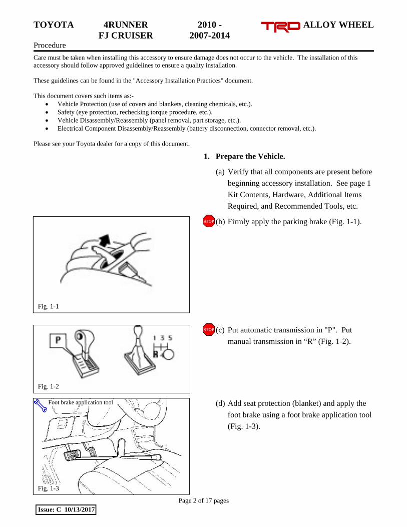
1. Prepare the Vehicle.
(a) Verify that all components are present before
beginning accessory installation. See page 1
Kit Contents, Hardware, Additional Items
Required, and Recommended Tools, etc.
(b) Firmly apply the parking brake (Fig. 1-1).
(c) Put automatic transmission in "P". Put
manual transmission in “R” (Fig. 1-2).
(d) Add seat protection (blanket) and apply the
foot brake using a foot brake application tool
(Fig. 1-3).
Fig. 1-3
Foot brake application tool
Fig. 1-2
Fig. 1-1
TOYOTA 4RUNNER 2010 - ALLOY WHEEL FJ CRUISER 2007-2014 Procedure
Page 3 of 17 pages Issue: C 10/13/2017
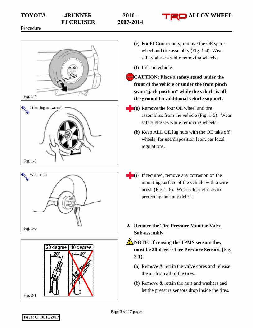
(e) For FJ Cruiser only, remove the OE spare
wheel and tire assembly (Fig. 1-4). Wear
safety glasses while removing wheels.
(f) Lift the vehicle.
CAUTION: Place a safety stand under the
front of the vehicle or under the front pinch
seam “jack position” while the vehicle is off
the ground for additional vehicle support.
(g) Remove the four OE wheel and tire
assemblies from the vehicle (Fig. 1-5). Wear
safety glasses while removing wheels.
(h) Keep ALL OE lug nuts with the OE take off
wheels, for use/disposition later, per local
regulations.
(i) If required, remove any corrosion on the
mounting surface of the vehicle with a wire
brush (Fig. 1-6). Wear safety glasses to
protect against any debris.
2. Remove the Tire Pressure Monitor Valve
Sub-assembly.
NOTE: If reusing the TPMS sensors they
must be 20-degree Tire Pressure Sensors (Fig.
2-1)!
(a) Remove & retain the valve cores and release
the air from all of the tires.
(b) Remove & retain the nuts and washers and
let the pressure sensors drop inside the tires.
Fig. 1-6
Wire brush
Fig. 2-1
Fig. 1-5
21mm lug nut wrench
Fig. 1-4
TOYOTA 4RUNNER 2010 - ALLOY WHEEL FJ CRUISER 2007-2014 Procedure
Page 4 of 17 pages Issue: C 10/13/2017
(c) Carefully separate the outer tire bead from
the wheel rim (Fig. 2-2).
NOTE: Be careful not to damage the tire
pressure monitor due to interference between the
sensor and tire bead.
(d) Remove the sensor from the tire and remove
the bead on the lower/inner side as in the
usual tire removal operation.
(e) Dismount the OE tire from the OE wheel.
(f) Repeat for all of the tires.
3. Install the Tire Pressure Monitor Sensor
(TPMS) Sub-assembly into the Accessory
Wheels.
(a) If the previously removed sensors are 20-
degree sensors, proceed to Step 3(c). If the
previously removed sensors are 40-degree
sensors, new 20-degree sensors must be
installed into the accessory wheels.
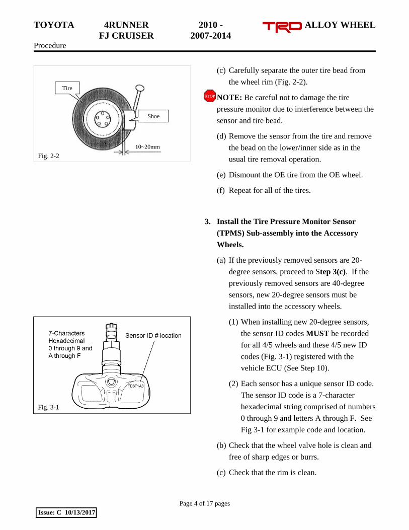
(1) When installing new 20-degree sensors,
the sensor ID codes MUST be recorded
for all 4/5 wheels and these 4/5 new ID
codes (Fig. 3-1) registered with the
vehicle ECU (See Step 10).
(2) Each sensor has a unique sensor ID code.
The sensor ID code is a 7-character
hexadecimal string comprised of numbers
0 through 9 and letters A through F. See
Fig 3-1 for example code and location.
(b) Check that the wheel valve hole is clean and
free of sharp edges or burrs.
(c) Check that the rim is clean.
Fig. 2-2
Tire
Shoe
10~20mm
Fig. 3-1
TOYOTA 4RUNNER 2010 - ALLOY WHEEL FJ CRUISER 2007-2014 Procedure
Page 5 of 17 pages Issue: C 10/13/2017
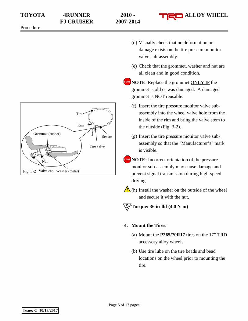
(d) Visually check that no deformation or
damage exists on the tire pressure monitor
valve sub-assembly.
(e) Check that the grommet, washer and nut are
all clean and in good condition.
NOTE: Replace the grommet ONLY IF the
grommet is old or was damaged. A damaged
grommet is NOT reusable.
(f) Insert the tire pressure monitor valve sub-
assembly into the wheel valve hole from the
inside of the rim and bring the valve stem to
the outside (Fig. 3-2).
(g) Insert the tire pressure monitor valve sub-
assembly so that the "Manufacturer’s" mark
is visible.
NOTE: Incorrect orientation of the pressure
monitor sub-assembly may cause damage and
prevent signal transmission during high-speed
driving.
(h) Install the washer on the outside of the wheel
and secure it with the nut.
Torque: 36 in-lbf (4.0 N-m)
4. Mount the Tires.
(a) Mount the P265/70R17 tires on the 17” TRD
accessory alloy wheels.
(b) Use tire lube on the tire beads and bead
locations on the wheel prior to mounting the
tire.
Rim
Tire
Nut
Grommet (rubber)
Tire valve
Washer (metal) Valve cap Fig. 3-2
Sensor
TOYOTA 4RUNNER 2010 - ALLOY WHEEL FJ CRUISER 2007-2014 Procedure
Page 6 of 17 pages Issue: C 10/13/2017
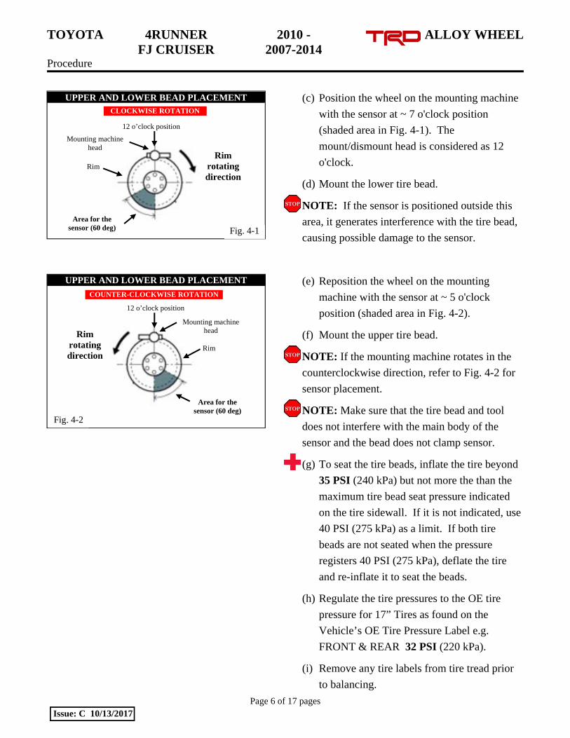
(c) Position the wheel on the mounting machine
with the sensor at ~ 7 o'clock position
(shaded area in Fig. 4-1). The
mount/dismount head is considered as 12
o'clock.
(d) Mount the lower tire bead.
NOTE: If the sensor is positioned outside this
area, it generates interference with the tire bead,
causing possible damage to the sensor.
(e) Reposition the wheel on the mounting
machine with the sensor at ~ 5 o'clock
position (shaded area in Fig. 4-2).
(f) Mount the upper tire bead.
NOTE: If the mounting machine rotates in the
counterclockwise direction, refer to Fig. 4-2 for
sensor placement.
NOTE: Make sure that the tire bead and tool
does not interfere with the main body of the
sensor and the bead does not clamp sensor.
(g) To seat the tire beads, inflate the tire beyond
35 PSI (240 kPa) but not more the than the
maximum tire bead seat pressure indicated
on the tire sidewall. If it is not indicated, use
40 PSI (275 kPa) as a limit. If both tire
beads are not seated when the pressure
registers 40 PSI (275 kPa), deflate the tire
and re-inflate it to seat the beads.
(h) Regulate the tire pressures to the OE tire
pressure for 17” Tires as found on the
Vehicle’s OE Tire Pressure Label e.g.
FRONT & REAR 32 PSI (220 kPa).
(i) Remove any tire labels from tire tread prior
to balancing.
Rim rotating direction
Area for the sensor (60 deg)
12 o’clock position
Mounting machine head
Rim
Fig. 4-1
UPPER AND LOWER BEAD PLACEMENT CLOCKWISE ROTATION
UPPER AND LOWER BEAD PLACEMENT
Rim rotating direction
Rim
Mounting machine head
12 o’clock position
Area for the sensor (60 deg)
Fig. 4-2
COUNTER-CLOCKWISE ROTATION

TOYOTA 4RUNNER 2010 - ALLOY WHEEL FJ CRUISER 2007-2014 Procedure
Page 7 of 17 pages Issue: C 10/13/2017
(j) Install and torque the valve stem cores with
the valve stem torque tool.
(k) Be sure to recheck the torque on the TPMS
nuts.
Torque: 36 in-lbf (4.0 N-m)
(l) Install the valve stem caps by hand.
5. Balance the Wheels.
NOTE: Application temperature for stick-on
type weight is above 50°F (10°C). It is good
practice to apply the stick-on type in sections
comprised of no more than 5 or 6 individual
weight segments.
(a) Prior to mounting stick-on weight, use VDC-
approved cleaner as needed to clean the
weight mounting location on the wheel, then
wipe down with a clean, dry, lint-free cloth.
Ensure that the location is clean and dry.
TOYOTA 4RUNNER 2010 - ALLOY WHEEL FJ CRUISER 2007-2014 Procedure
Page 8 of 17 pages Issue: C 10/13/2017
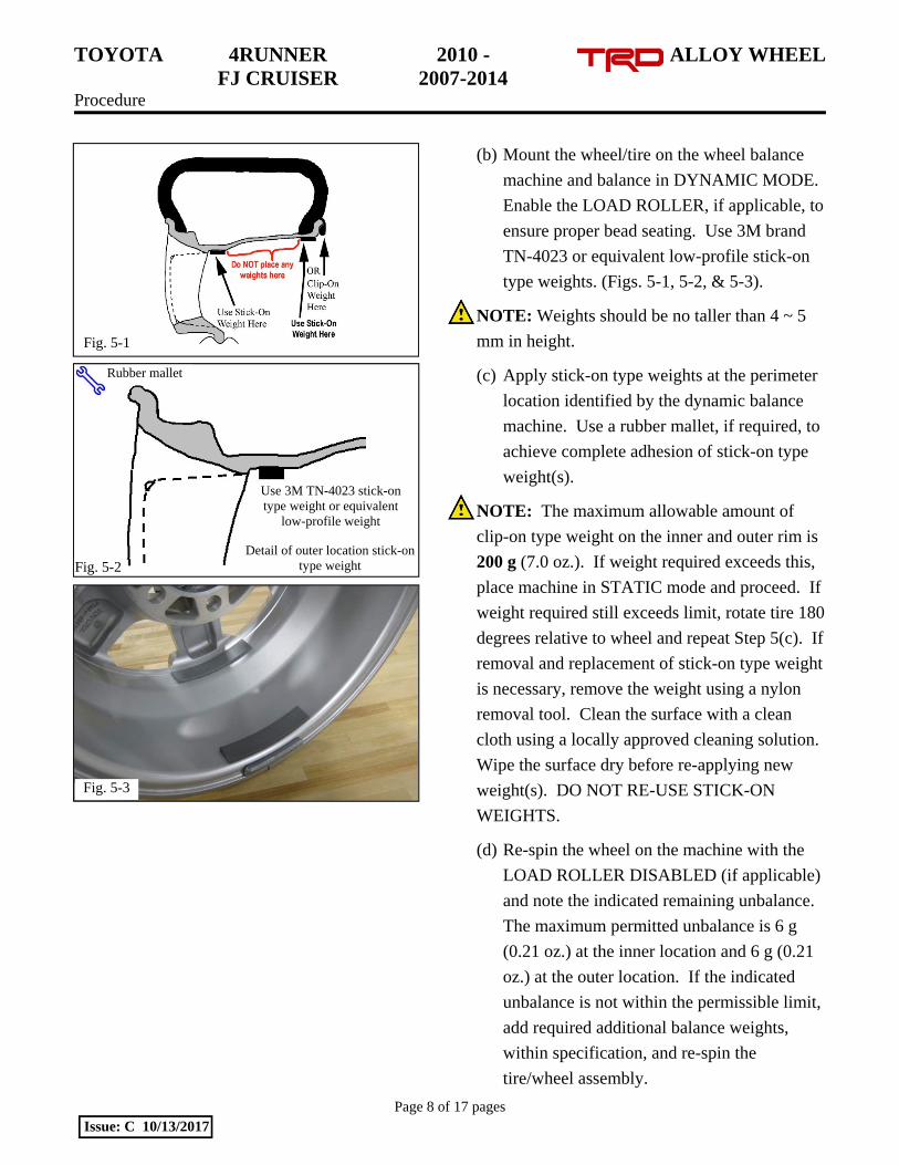
(b) Mount the wheel/tire on the wheel balance
machine and balance in DYNAMIC MODE.
Enable the LOAD ROLLER, if applicable, to
ensure proper bead seating. Use 3M brand
TN-4023 or equivalent low-profile stick-on
type weights. (Figs. 5-1, 5-2, & 5-3).
NOTE: Weights should be no taller than 4 ~ 5
mm in height.
(c) Apply stick-on type weights at the perimeter
location identified by the dynamic balance
machine. Use a rubber mallet, if required, to
achieve complete adhesion of stick-on type
weight(s).
NOTE: The maximum allowable amount of
clip-on type weight on the inner and outer rim is
200 g (7.0 oz.). If weight required exceeds this,
place machine in STATIC mode and proceed. If
weight required still exceeds limit, rotate tire 180
degrees relative to wheel and repeat Step 5(c). If
removal and replacement of stick-on type weight
is necessary, remove the weight using a nylon
removal tool. Clean the surface with a clean
cloth using a locally approved cleaning solution.
Wipe the surface dry before re-applying new
weight(s). DO NOT RE-USE STICK-ON
WEIGHTS.
(d) Re-spin the wheel on the machine with the
LOAD ROLLER DISABLED (if applicable)
and note the indicated remaining unbalance.
The maximum permitted unbalance is 6 g
(0.21 oz.) at the inner location and 6 g (0.21
oz.) at the outer location. If the indicated
unbalance is not within the permissible limit,
add required additional balance weights,
within specification, and re-spin the
tire/wheel assembly.
Fig. 5-2 Detail of outer location stick-on
type weight
Use 3M TN-4023 stick-on type weight or equivalent
low-profile weight
Rubber mallet
Fig. 5-1
Fig. 5-3
TOYOTA 4RUNNER 2010 - ALLOY WHEEL FJ CRUISER 2007-2014 Procedure
Page 9 of 17 pages Issue: C 10/13/2017
6. Record the Tire Identification Numbers (TIN).
(a) PPO Only: Record ALL new Tire
Identification Numbers (TINs) from the four
or five new tires installed onto the vehicle.
(1) Record these TINs with the Vehicle
Identification Number (VIN) per VDC
process.
(2) The TIN for the tire is an 11 or 12-
character string located after the “DOT”
symbol on the sidewall of the tire.
(3) Refer to SPAD PPO Bulletin database as
needed. When reusing the same OE tires
that came on the same vehicle, the TINs
need not be recorded.
(b) DIO Only: Record ALL new Tire
Identification Numbers (TINs) from the four
or five new tires installed onto the vehicle.
(1) Record these TINs with the Vehicle
Identification Number (VIN).
(2) Provide the tire information to your tire
vendor as required by law.
(3) When reusing the same OE tires that
came on the same vehicle, the TINs need
not be recorded.
TOYOTA 4RUNNER 2010 - ALLOY WHEEL FJ CRUISER 2007-2014 Procedure
Page 10 of 17 pages Issue: C 10/13/2017
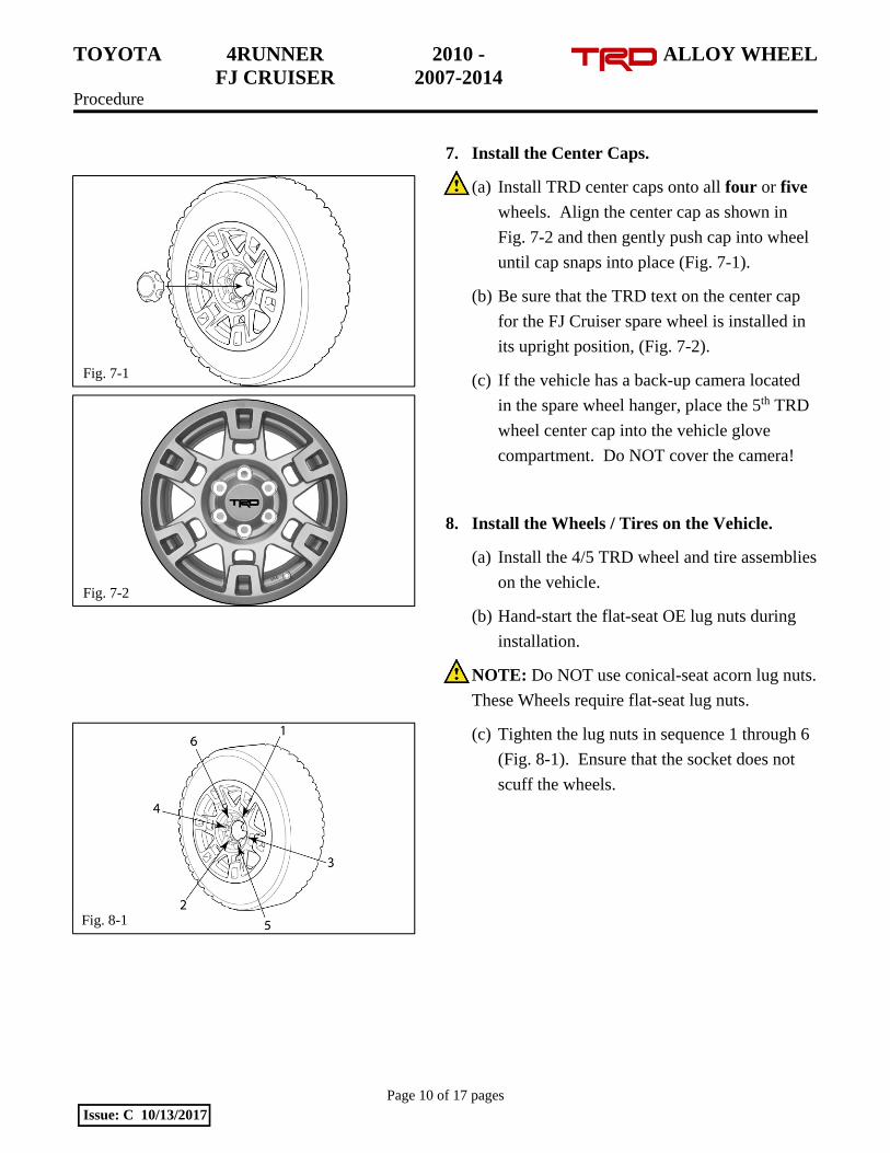
7. Install the Center Caps.
(a) Install TRD center caps onto all four or five
wheels. Align the center cap as shown in
Fig. 7-2 and then gently push cap into wheel
until cap snaps into place (Fig. 7-1).
(b) Be sure that the TRD text on the center cap
for the FJ Cruiser spare wheel is installed in
its upright position, (Fig. 7-2).
(c) If the vehicle has a back-up camera located
in the spare wheel hanger, place the 5th TRD
wheel center cap into the vehicle glove
compartment. Do NOT cover the camera!
8. Install the Wheels / Tires on the Vehicle.
(a) Install the 4/5 TRD wheel and tire assemblies
on the vehicle.
(b) Hand-start the flat-seat OE lug nuts during
installation.
NOTE: Do NOT use conical-seat acorn lug nuts.
These Wheels require flat-seat lug nuts.
(c) Tighten the lug nuts in sequence 1 through 6
(Fig. 8-1). Ensure that the socket does not
scuff the wheels.
Fig. 7-1
Fig. 7-2
Fig. 8-1

TOYOTA 4RUNNER 2010 - ALLOY WHEEL FJ CRUISER 2007-2014 Procedure
Page 11 of 17 pages Issue: C 10/13/2017
(d) Tighten the lug nuts in sequence 1 through 6
or equivalent star pattern (Fig. 8-2). Ensure
that the socket does not scuff the wheels.
Tighten to 83 ft-lbf (112 N-m) using a torque
wrench.
Torque: 83 ft-lbf (112 N-m)
CAUTION: DO NOT USE AN IMPACT
WRENCH TO INSTALL OR REMOVE
WHEEL LOCKS.
(e) Re-torque all lug nuts in the same 1-6
sequence (Fig. 8-2).
Torque: 83 ft-lbf (112 N-m)
(f) With the vehicle still on the lift, use a digital
torque wrench to measure the torque of each
lug nut/lock, and TPMS nut. Record the
values on the Torque Audit Sheet (Fig. 8-3)
(PPO installation only, does not apply to DIO
installation).
(g) Lower the vehicle.
(h) FJ Cruiser Only: Use the OE lug nuts to
install the spare wheel/tire on the vehicle
(Fig. 8-4). Use a torque wrench to tighten
the nuts to 65 ft-lbf (88 N-m).
Torque: 65 ft-lbf (88 N-m)
(i) Discard the OE take-off wheels per local
regulations.
1
3
2
4 5
6
Fig. 8-2
Torque 2 Cycles (All Lugs/Locks)
2x
Fig. 8-3
Measure Torque and Document (All Lugs/Locks)
TOYOTA 4RUNNER 2010 - ALLOY WHEEL FJ CRUISER 2007-2014 Procedure
Page 12 of 17 pages Issue: C 10/13/2017
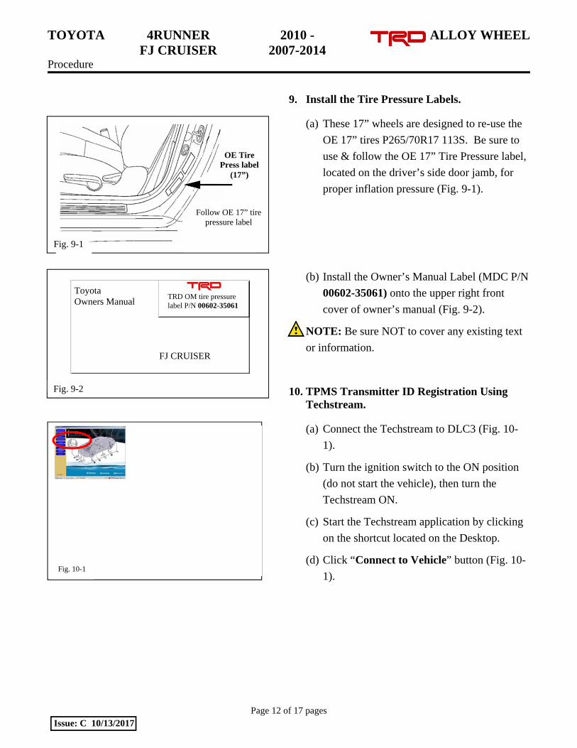
9. Install the Tire Pressure Labels.
(a) These 17” wheels are designed to re-use the
OE 17” tires P265/70R17 113S. Be sure to
use & follow the OE 17” Tire Pressure label,
located on the driver’s side door jamb, for
proper inflation pressure (Fig. 9-1).
(b) Install the Owner’s Manual Label (MDC P/N
00602-35061) onto the upper right front
cover of owner’s manual (Fig. 9-2).
NOTE: Be sure NOT to cover any existing text
or information.
10. TPMS Transmitter ID Registration Using Techstream.
(a) Connect the Techstream to DLC3 (Fig. 10-
1).
(b) Turn the ignition switch to the ON position
(do not start the vehicle), then turn the
Techstream ON.
(c) Start the Techstream application by clicking
on the shortcut located on the Desktop.
(d) Click “Connect to Vehicle” button (Fig. 10-
1).
OE Tire Press label
(17”)
Fig. 9-1
Follow OE 17” tire pressure label
Toyota Owners Manual
TRD OM tire pressure label P/N 00602-35061
Fig. 9-2
FJ CRUISER
Fig. 10-1
TOYOTA 4RUNNER 2010 - ALLOY WHEEL FJ CRUISER 2007-2014 Procedure
Page 13 of 17 pages Issue: C 10/13/2017
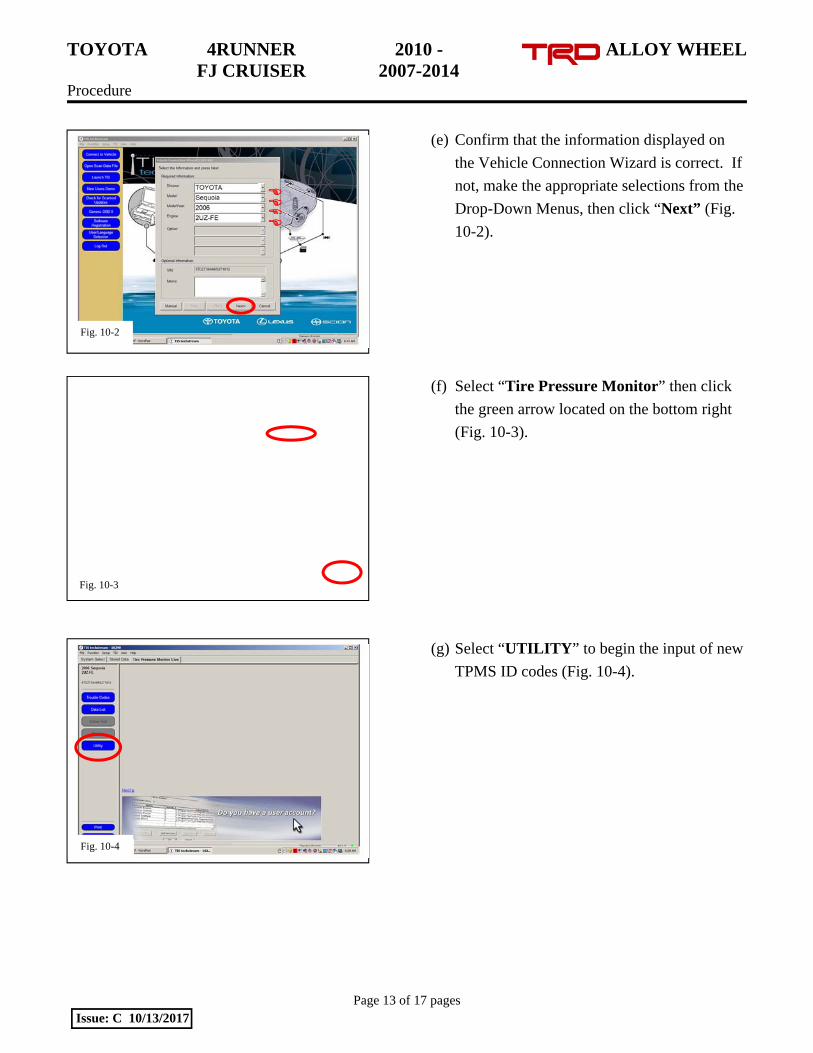
(e) Confirm that the information displayed on
the Vehicle Connection Wizard is correct. If
not, make the appropriate selections from the
Drop-Down Menus, then click “Next” (Fig.
10-2).
(f) Select “Tire Pressure Monitor” then click
the green arrow located on the bottom right
(Fig. 10-3).
(g) Select “UTILITY” to begin the input of new
TPMS ID codes (Fig. 10-4).
Fig. 10-4
Fig. 10-2
Fig. 10-3
TOYOTA 4RUNNER 2010 - ALLOY WHEEL FJ CRUISER 2007-2014 Procedure
Page 14 of 17 pages Issue: C 10/13/2017
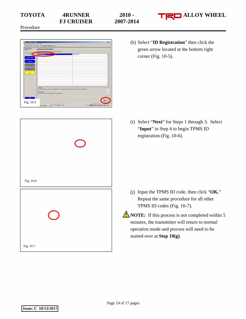
(h) Select “ID Registration” then click the
green arrow located at the bottom right
corner (Fig. 10-5).
(i) Select “Next” for Steps 1 through 3. Select
“Input” in Step 4 to begin TPMS ID
registration (Fig. 10-6).
(j) Input the TPMS ID code, then click “OK.”
Repeat the same procedure for all other
TPMS ID codes (Fig. 10-7).
NOTE: If this process is not completed within 5
minutes, the transmitter will return to normal
operation mode and process will need to be
started over at Step 10(g).
Fig. 10-5
Fig. 10-6
Fig. 10-7

TOYOTA 4RUNNER 2010 - ALLOY WHEEL FJ CRUISER 2007-2014 Procedure
Page 15 of 17 pages Issue: C 10/13/2017
(k) After all TPMS ID numbers have been
registered, “ID Registration is complete”
text should be displayed. Click “Exit” to
finish the registration process (Fig. 10-8).
(l) Select “DATA LIST” to view and confirm
the TPMS ID numbers have been correctly
registered (Fig 10-9).
11. Breakdown the OE Tire & Wheel Assembly.
(a) Sort product properly per local regulations.
(b) PPO Only: Take-Off Wheels get salvaged
according to local regulations.
12. Place the Lug Nut Tool.
(a) If optional wheel locks were installed, attach
wheel lock key tool to vehicle lug wrench
using optional cable tie.
(b) Trim the cable tie and replace the lug wrench
into lug wrench tool bag.
(c) Place the associated wheel lock paperwork
into the plastic bag and place the bag into the
vehicle glove compartment.
Fig. 10-8
Fig. 10-9
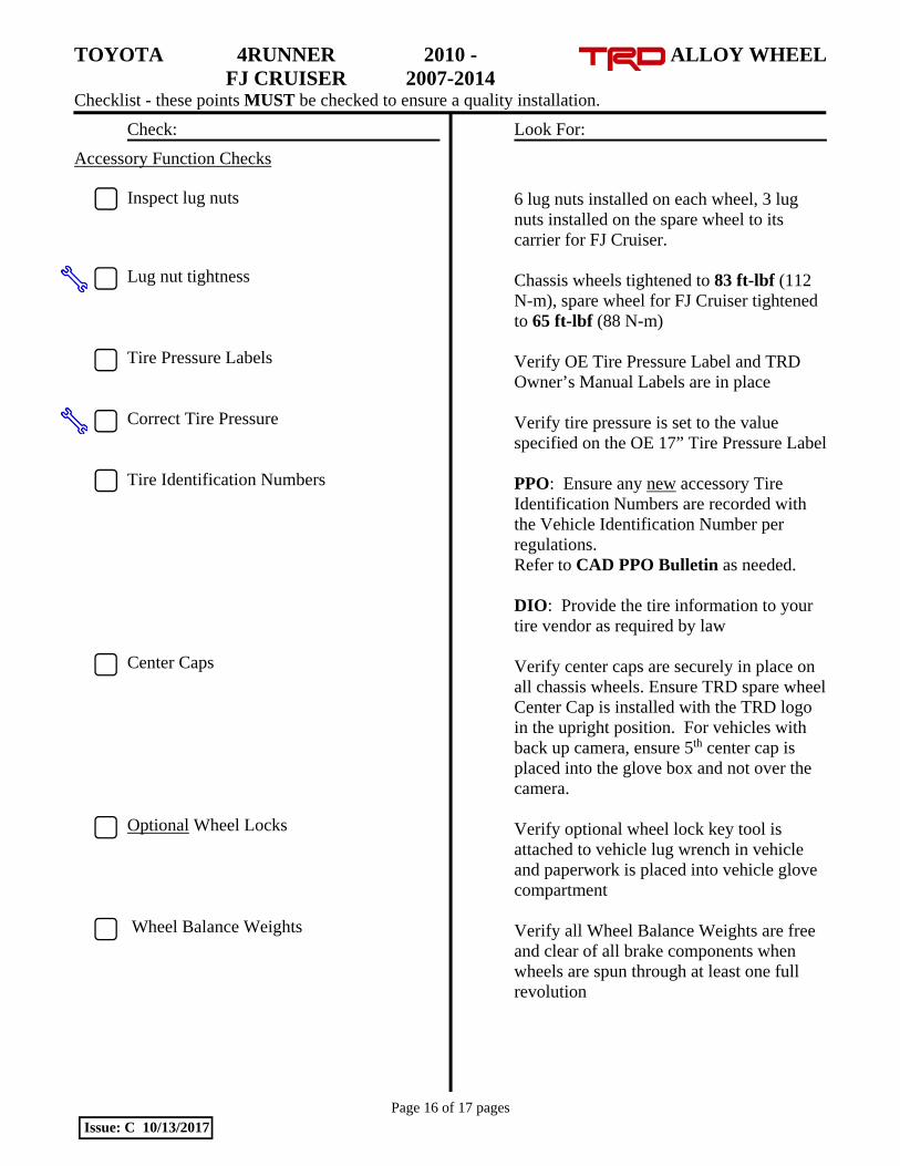
TOYOTA 4RUNNER 2010 - ALLOY WHEEL FJ CRUISER 2007-2014 Checklist - these points MUST be checked to ensure a quality installation.
Check: Look For:
Page 16 of 17 pages Issue: C 10/13/2017
Accessory Function Checks
Inspect lug nuts
Lug nut tightness Tire Pressure Labels Correct Tire Pressure Tire Identification Numbers Center Caps Optional Wheel Locks Wheel Balance Weights
6 lug nuts installed on each wheel, 3 lug nuts installed on the spare wheel to its carrier for FJ Cruiser. Chassis wheels tightened to 83 ft-lbf (112 N-m), spare wheel for FJ Cruiser tightened to 65 ft-lbf (88 N-m) Verify OE Tire Pressure Label and TRD Owner’s Manual Labels are in place Verify tire pressure is set to the value specified on the OE 17” Tire Pressure Label PPO: Ensure any new accessory Tire Identification Numbers are recorded with the Vehicle Identification Number per regulations. Refer to CAD PPO Bulletin as needed. DIO: Provide the tire information to your tire vendor as required by law Verify center caps are securely in place on all chassis wheels. Ensure TRD spare wheel Center Cap is installed with the TRD logo in the upright position. For vehicles with back up camera, ensure 5th center cap is placed into the glove box and not over the camera. Verify optional wheel lock key tool is attached to vehicle lug wrench in vehicle and paperwork is placed into vehicle glove compartment Verify all Wheel Balance Weights are free and clear of all brake components when wheels are spun through at least one full revolution

TOYOTA 4RUNNER 2010 - ALLOY WHEEL FJ CRUISER 2007-2014 Checklist - these points MUST be checked to ensure a quality installation.
Check: Look For:
Page 17 of 17 pages Issue: C 10/13/2017
Vehicle Appearance Check
After accessory installation and removal of protective cover(s), perform a visual inspection.
Ensure no damage (including scuffs and scratches) was caused during the installation process. (For PPO installations, refer to TMS Accessory Quality Shipping Standard.)