Embed Size (px)
Citation preview
TOYOTA 4RUNNER 3rd Generation 1996-2002
Thank you for choosing White Knuckle Rock Sliders Please read the instructions before beginning installation. Check hardware kit contents against content list
below. Also, check the tools needed against the list below. Hardware Kit Tools Needed 1-Driver Side Rock Slider 3/8” Drill 1-Passenger Side Rock Slider 1/8”, 5/16” Drill Bits 14 each 3/8”x 1” Thread Cutting Bolts Center Punch and Hammer 3 each 1/2" x 4” Grade 8 Bolts, Nuts, Air Impact if available Flat Washers, and Lock Washers 3/4” Wrenches 1 each 1/2" x 3-1/2” Grade 8 Bolts, 9/16” Socket and Ratchet Flat Washer, Lock Washer (Driver Side Rear) 2 Axle Stands 3 each 3/16” x 2” x 3” Backing Plates with Welded Nut Bottle Jack 1 each 3/16” x 2” x 3” Backing Plate with Welded Nut “C” Clamps INSTALLATION INSTRUCTIONS
1. Place the axle stands or jack directly under the rocker panel. Place the slider on the axle stands or jack Figure 1. If equipped, the rear fender flare may need to be trimmed to allow for the rear of the slider.
2. The factory holes in the frame should be aligned to allow the 1/2” x 4” and 3-1/2” bolts to go thru the mounting plates and the frame. NOTE: The driver side rear backing plate will go between the frame and gas tank. The easiest method to start the bolt through the backing plate is to remove the bolts from the front and side of the gas tank skid plate to allow the tank to hang out of the way. Make sure to put an axle stand under the tank to prevent it from dropping any lower than needed Figure 6. Reinstall the gas tank skid once the slider has been installed.
3. Push the 1/2” x 4” and 3-1/2” bolt, lock washer and flat washer thru the factory hole of the center and rear mounting plates and begin threading into the nut welded to the 2” x 3” backing plate Figure 2. Keep the bolts loose for the time being to allow for adjustment of the slider position.
4. Now adjust the slider front to rear in the desired position. Clamp the front mounting plates to the frame and tighten the 1/2" x 4” and 3-1/2” bolts thru the factory frame holes Figure 3. “C” clamps should be as high as possible on the mounting plate to eliminate any gap between the frame and the top of the vertical portion of the mounting plate. Make sure the bottom of the “L” mounting plates are snug under the frame. A bottle jack can be used to achieve this.
5. Stand back to take a look at the slider in relation to the vehicle body. Make sure the rock slider is in the desired position, level, and no gaps between the frame and the mounting plates. Mark the holes to be drilled on the underside of the frame and the one on the face of the frame thru the front mounting plate with the center punch by drawing a circle inside the hole.
6. Remove the slider and use the center punch on each of these marks for pre-drilling. 7. Drill a small pilot hole thru each of the marks and re-drill with the 5/16” drill bit. Make sure to
keep the drill perpendicular to the frame when drilling the holes Figure 4.
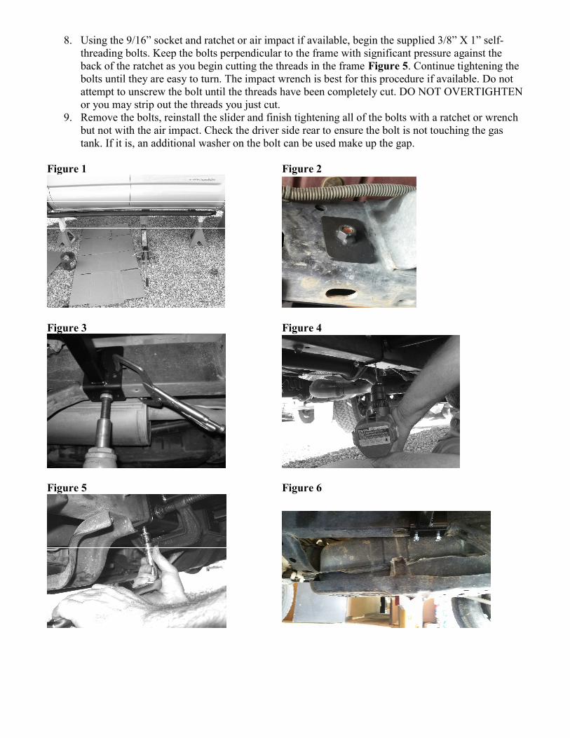
8. Using the 9/16” socket and ratchet or air impact if available, begin the supplied 3/8” X 1” self-threading bolts. Keep the bolts perpendicular to the frame with significant pressure against the back of the ratchet as you begin cutting the threads in the frame Figure 5. Continue tightening the bolts until they are easy to turn. The impact wrench is best for this procedure if available. Do not attempt to unscrew the bolt until the threads have been completely cut. DO NOT OVERTIGHTEN or you may strip out the threads you just cut.
9. Remove the bolts, reinstall the slider and finish tightening all of the bolts with a ratchet or wrench but not with the air impact. Check the driver side rear to ensure the bolt is not touching the gas tank. If it is, an additional washer on the bolt can be used make up the gap.
Figure 1 Figure 2
Figure 3 Figure 4
Figure 5 Figure 6
SAFETY FIRST
Observe proper safety procedures during installation. Improperly used tools and unsafe procedures can cause injury or death. Refer to
manufacturers manuals for use and warnings of tools to be used. Modifications to your vehicle can cause dangerous conditions. The
buyers and users of this product assume all risks associated with the installation and use of this product. All installations should be made by
a qualified mechanic.
DISCLAIMER
White Knuckle Off Road Products, LLC stands behind all of our quality off-road fabricated products. WKORP will not be held responsible nor will we
accept liability for failure of parts as a result of extreme off-road use. Minor modifications may be required to allow the installation of our products. Modifications to your vehicle using products manufactured by WKORP
may create dangerous conditions. Modifications to your vehicle are done at your own risk. WKORP will not accept responsibility or liability from
damage or personal injury caused by installing or using installed products manufactured by WKORP whether intended or unintended. The buyer accepts all responsibility and risks associated with any modifications
using WKORP manufactured products. All products manufactured by White Knuckle Off Road Products, LLC are for off-road use only.
The powder coated finish provided by WKORP will carry no warranty or guarantee. The powder coated finish is provided as a service. Any damage to the finish during shipping must be reported immediately. Any damage,
wear, or anomalies incurred to the finish after receiving parts from WKORP are the responsibility of the buyer or user.
www.white-knuckleoffroad.com