Embed Size (px)
Citation preview
TOYOTA CAMRY HYBRID 2015– TVIP V4PREPARATION REMOTE ENGINE STARTER (RES)
Page 1 of 32Issue: B : 09/25/14
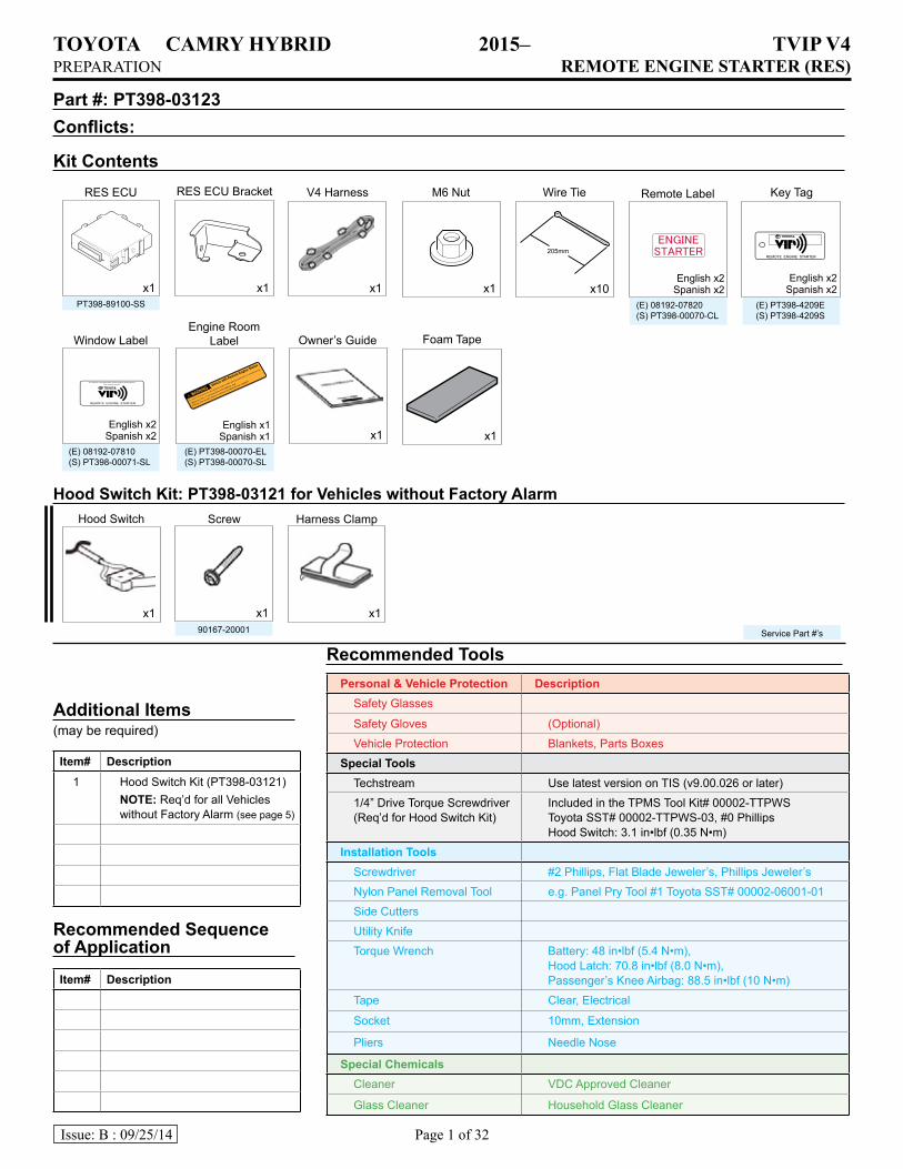
RES ECU Bracket
90167-20001
(E) 08192-07810(S) PT398-00071-SL
(E) PT398-00070-EL(S) PT398-00070-SL
(E) PT398-4209E(S) PT398-4209S
(E) 08192-07820(S) PT398-00070-CL
PT398-89100-SS
Part #: PT398-03123 Conflicts:
RecommendedToolsPersonal&VehicleProtection Description
Safety Glasses
Safety Gloves (Optional)
Vehicle Protection Blankets, Parts Boxes
SpecialToolsTechstream Use latest version on TIS (v9.00.026 or later)
1/4” Drive Torque Screwdriver (Req’d for Hood Switch Kit)
Included in the TPMS Tool Kit# 00002-TTPWS Toyota SST# 00002-TTPWS-03, #0 Phillips Hood Switch: 3.1 in•lbf (0.35 N•m)
InstallationToolsScrewdriver #2 Phillips, Flat Blade Jeweler’s, Phillips Jeweler’s
Nylon Panel Removal Tool e.g. Panel Pry Tool #1 Toyota SST# 00002-06001-01
Side Cutters
Utility Knife
Torque Wrench Battery: 48 in•lbf (5.4 N•m), Hood Latch: 70.8 in•lbf (8.0 N•m), Passenger’s Knee Airbag: 88.5 in•lbf (10 N•m)
Tape Clear, Electrical
Socket 10mm, Extension
Pliers Needle Nose
SpecialChemicalsCleaner VDC Approved Cleaner
Glass Cleaner Household Glass Cleaner
x1 x1x1 x1
KitContentsRES ECU V4 Harness M6 Nut Key TagWire Tie Remote Label
x10
x1
Window LabelEngine Room
Label
Hood Switch Screw
Owner’s Guide
AdditionalItems(may be required)
Item# Description1 Hood Switch Kit (PT398-03121)
NOTE: Req’d for all Vehicles without Factory Alarm (see page 5)
RecommendedSequenceofApplicationItem# Description
Service Part #’s
English x2Spanish x2
English x2Spanish x2
English x2Spanish x2
English x1Spanish x1
x1 x1 x1
Harness Clamp
HoodSwitchKit:PT398-03121forVehicleswithoutFactoryAlarm
x1
Foam Tape
TOYOTA CAMRY HYBRID 2015– TVIP V4PREPARATION REMOTE ENGINE STARTER (RES)
Page 2 of 32Issue: B : 09/25/14
TableofContentsI. Preparation ............................................................................................................................ 1 – 4
1. Table of Contents ................................................................................................................................................22. Wire Routing Overview ...................................................................................................................................3-4
II. Procedure ............................................................................................................................5 – 2 91. Hood Switch Installation. ..............................................................................................................52. Vehicle Disassembly . ................................................................................................................ 133. RES ECU Preparation and Installation. .......................................................................................... 164. V4 Harness Installation. .............................................................................................................. 195. Registration Preparation. ............................................................................................................ 226. Registration. ............................................................................................................................ 237. Complete the Installation. ........................................................................................................... 288. Tags and Labels. ....................................................................................................................... 29
III. Checklist ........................................................................................................................... 3 0 – 3 21. Accessory Function Checks ..............................................................................................................................302. Vehicle Appearance Checks .............................................................................................................................303. Vehicle Function Checks ...................................................................................................................................31
AccessoryInstallationPractice(readbeforeinstallation)Care must be taken when installing this accessory to ensure damage does not occur to the vehicle. The installation of this accessory should follow approved guidelines to ensure a quality installation.These guidelines can be found in the “Accessory Installation Practices” document.This document covers such items as:
• Vehicle Protection (use of covers and blankets, cleaning chemicals, etc.)• Safety (eye protection, checking torque procedure, etc.)• Vehicle Disassembly/Reassembly (panel removal, part storage, etc.)• Electrical Component Disassembly/Reassembly (battery disconnection,
connector removal, etc.)Please see your TOYOTA dealer for a copy of this document.
LegendDo not proceed until process has been completed.
Follow steps carefully to avoid damaging the Vehicle or AccessoryUse caution to avoid injury.
Used in Figures to call attention to specific tools recommended for the process.
Highlights a change in installation with respect to previous issue.
Indicates that torque is related to safety.
Video available; click to play.
Wire Tie location and number.xx
TOY
OTA
CA
MR
Y H
YB
RID
2015–
TV
IP V4
PREPA
RATIO
N
RE
MO
TE
EN
GIN
E STA
RT
ER
(RE
S)
Page 3 of 32Issue: B
: 09/25/14
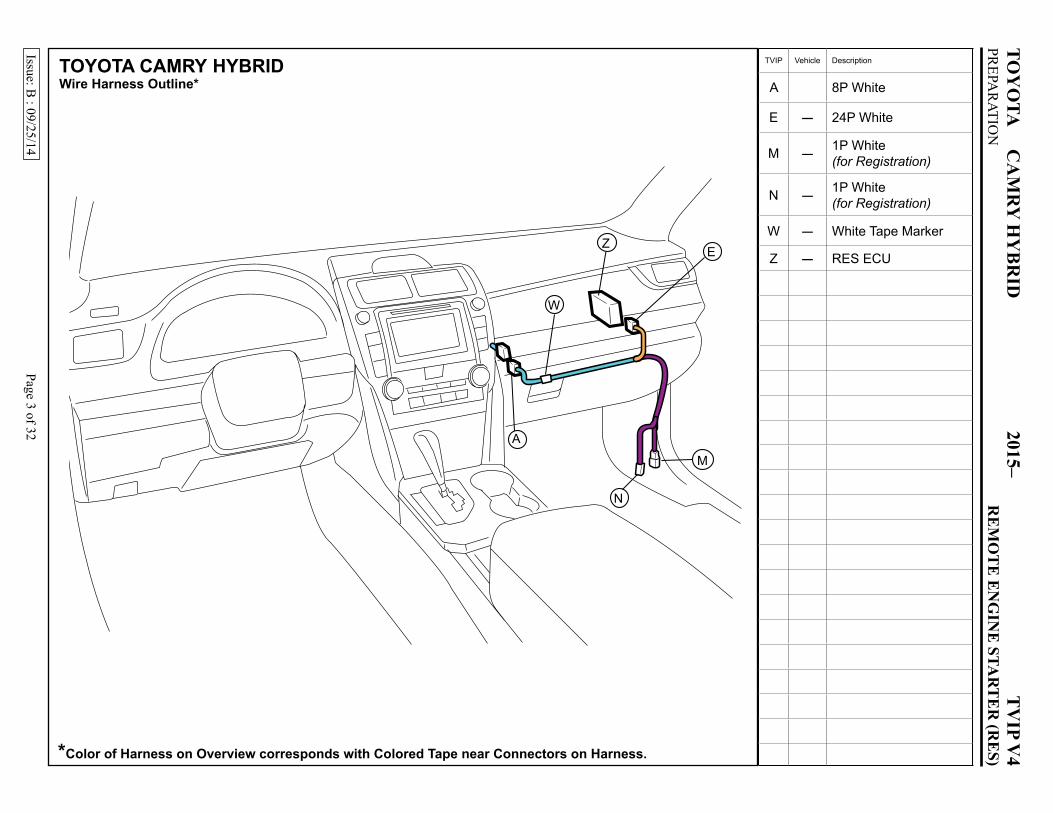
TOYOTA CAMRY HYBRIDWireHarnessOutline*
*ColorofHarnessonOverviewcorrespondswithColoredTapenearConnectorsonHarness.
TVIP Vehicle Description
A 8P White
E - 24P White
M - 1P White (for Registration)
N - 1P White (for Registration)
W - White Tape Marker
Z - RES ECU
M
N
EZ
A
W
TOY
OTA
CA
MR
Y H
YB
RID
2015–
TV
IP V4
PREPA
RATIO
N
RE
MO
TE
EN
GIN
E STA
RT
ER
(RE
S)
Page 4 of 32Issue: B
: 09/25/14
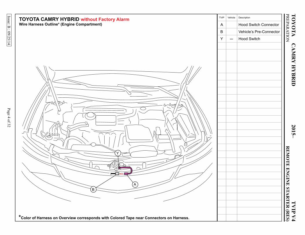
TOYOTA CAMRY HYBRID withoutFactoryAlarm WireHarnessOutline*(EngineCompartment)
*ColorofHarnessonOverviewcorrespondswithColoredTapenearConnectorsonHarness.
BA
Y
TVIP Vehicle Description
A Hood Switch Connector
B Vehicle’s Pre-Connector
Y - Hood Switch
TOYOTA CAMRY HYBRID 2015– TVIP V4PROCEDURE REMOTE ENGINE STARTER (RES)
Page 5 of 32Issue: B : 09/25/14
Confirmthefollowing:Beforebeginning,closetheHoodandtheDoors.Presstheremotecontrol’slockbutton.
UNLOCK
UNLOCK
UNLOCK
ObservetheSecurityLEDonthecenterconsole
Blinking
SecurityLEDTurnsONsolidfor30Secondsthenstartsblinking
WITHFactoryAlarm (VehiclehasHoodSwitch)
SecurityLEDstartsblinking Immediately
WITHOUTFactoryAlarm (VehicledoesnothaveHoodSwitch)
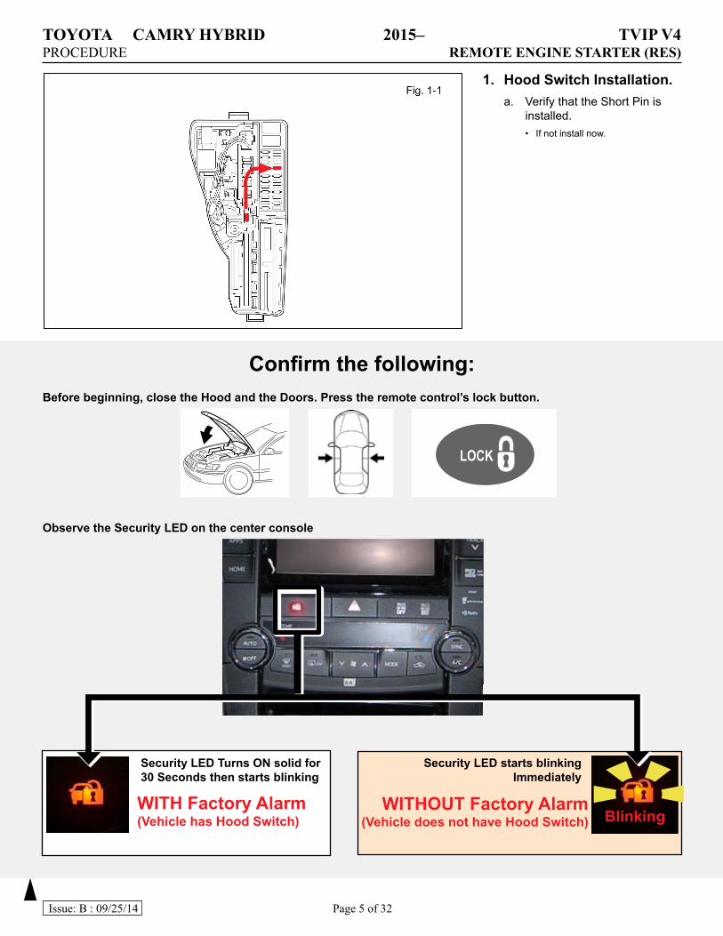
1. HoodSwitchInstallation.a. Verify that the Short Pin is
installed.• If not install now.
TOYOTA CAMRY HYBRID 2015– TVIP V4PROCEDURE REMOTE ENGINE STARTER (RES)
Page 6 of 32Issue: B : 09/25/14
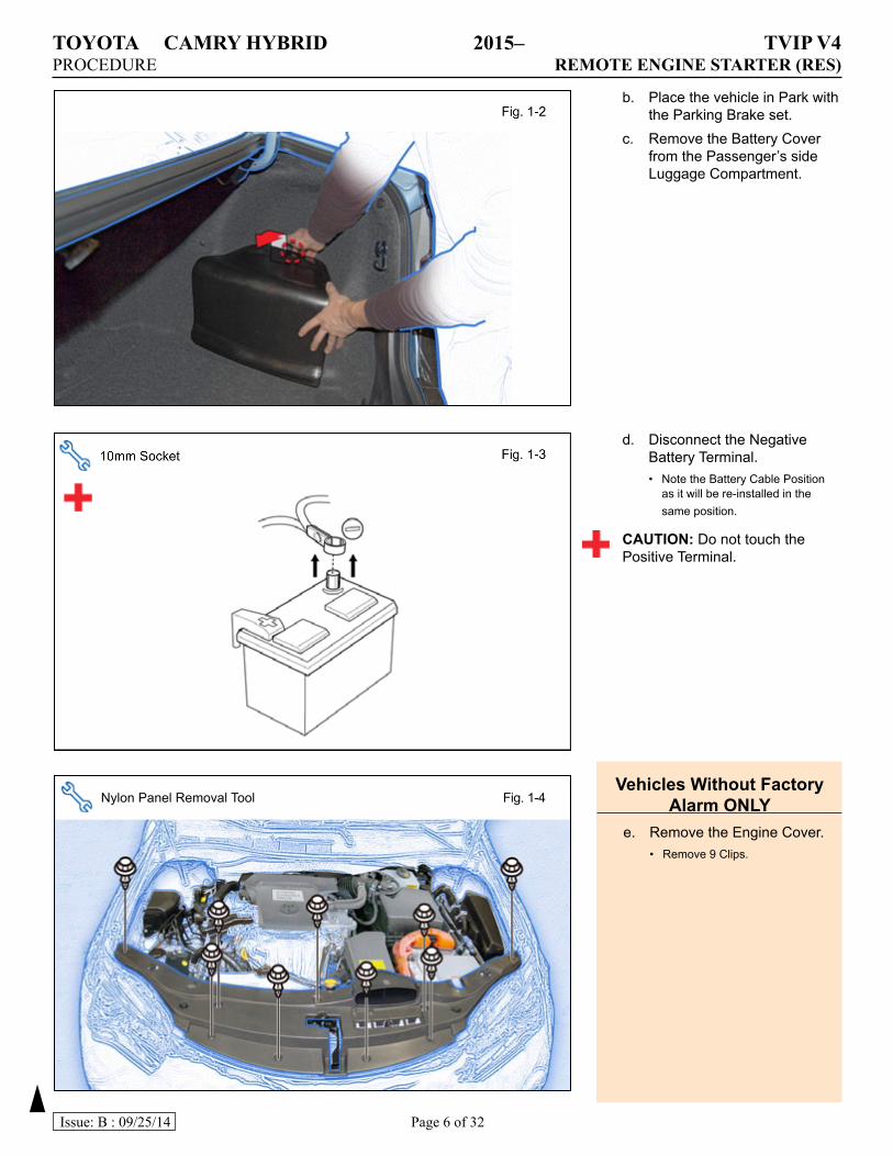
b. Place the vehicle in Park with the Parking Brake set.
c. Remove the Battery Cover from the Passenger’s side Luggage Compartment.
d. Disconnect the Negative Battery Terminal.• Note the Battery Cable Position
as it will be re-installed in the same position.
CAUTION: Do not touch the Positive Terminal.
Nylon Panel Removal Tool Fig. 1-4VehiclesWithoutFactory
AlarmONLYe. Remove the Engine Cover.
• Remove 9 Clips.
TOYOTA CAMRY HYBRID 2015– TVIP V4PROCEDURE REMOTE ENGINE STARTER (RES)
Page 7 of 32Issue: B : 09/25/14
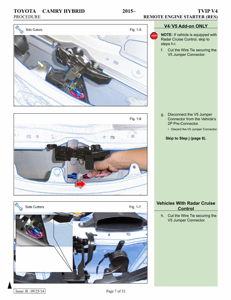
V4/V5Add-onONLY
NOTE: If vehicle is equipped with Radar Cruise Control, skip to steps h-i.f. Cut the Wire Tie securing the
V5 Jumper Connector.
g. Disconnect the V5 Jumper Connector from the Vehicle’s 2P Pre-Connector.• Discard the V5 Jumper Connector.
SkiptoStepj(page8).
VehiclesWithRadarCruiseControl
h. Cut the Wire Tie securing the V5 Jumper Connector.
TOYOTA CAMRY HYBRID 2015– TVIP V4PROCEDURE REMOTE ENGINE STARTER (RES)
Page 8 of 32Issue: B : 09/25/14
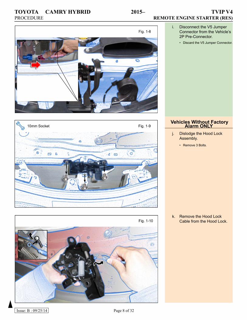
VehiclesWithoutFactoryAlarmONLY
j. Dislodge the Hood Lock Assembly.• Remove 3 Bolts.
k. Remove the Hood Lock Cable from the Hood Lock.
i. Disconnect the V5 Jumper Connector from the Vehicle’s 2P Pre-Connector.• Discard the V5 Jumper Connector.
TOYOTA CAMRY HYBRID 2015– TVIP V4PROCEDURE REMOTE ENGINE STARTER (RES)
Page 9 of 32Issue: B : 09/25/14
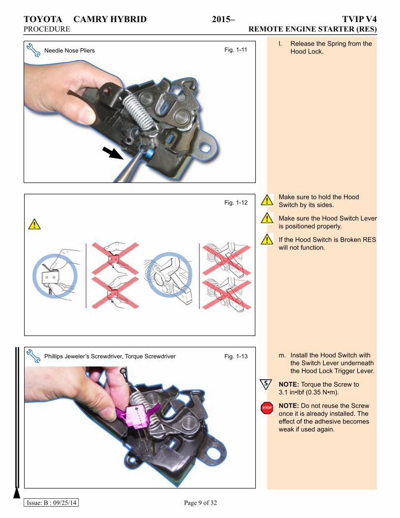
l. Release the Spring from the Hood Lock.
Make sure to hold the Hood Switch by its sides.
Make sure the Hood Switch Lever is positioned properly.
If the Hood Switch is Broken RES will not function.
m. Install the Hood Switch with the Switch Lever underneath the Hood Lock Trigger Lever.
NOTE: Torque the Screw to 3.1 in•lbf (0.35 N•m).
NOTE: Do not reuse the Screw once it is already installed. The effect of the adhesive becomes weak if used again.
Needle Nose Pliers Fig. 1-11
Fig. 1-12
Phillips Jeweler’s Screwdriver, Torque Screwdriver Fig. 1-13
TOYOTA CAMRY HYBRID 2015– TVIP V4PROCEDURE REMOTE ENGINE STARTER (RES)
Page 10 of 32Issue: B : 09/25/14
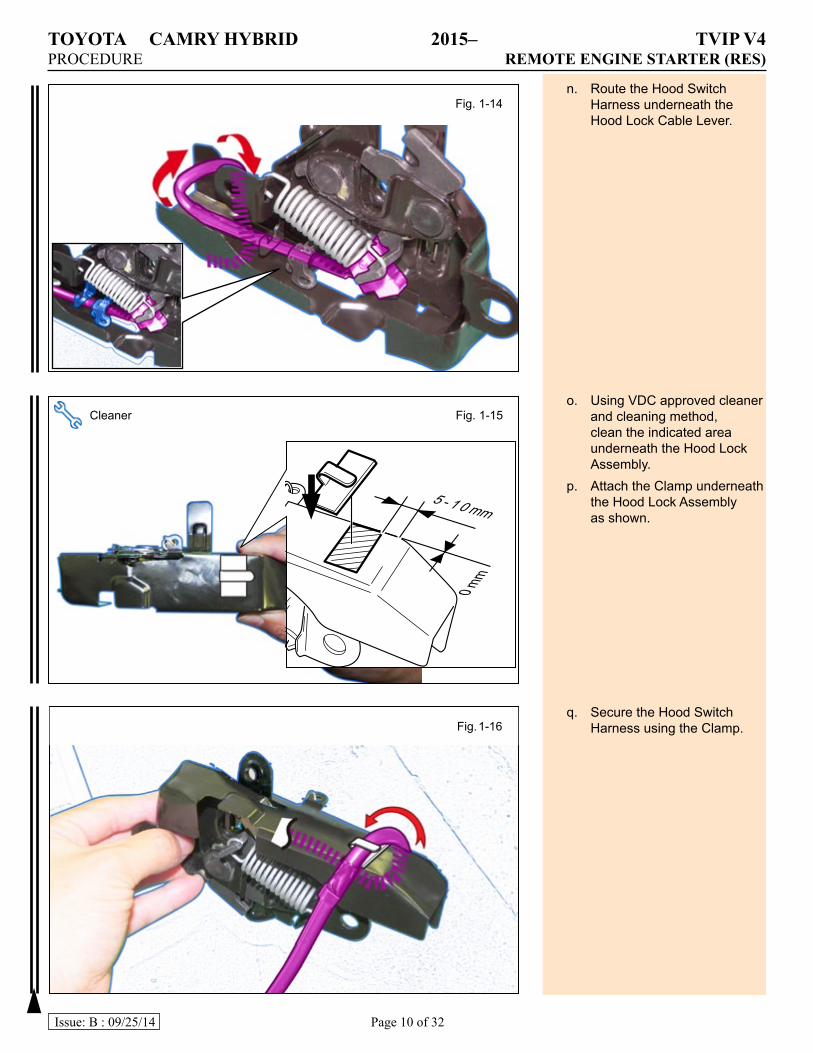
n. Route the Hood Switch Harness underneath the Hood Lock Cable Lever.
o. Using VDC approved cleaner and cleaning method, clean the indicated area underneath the Hood Lock Assembly.
p. Attach the Clamp underneath the Hood Lock Assembly as shown.
q. Secure the Hood Switch Harness using the Clamp.
Fig. 1-14
Cleaner Fig. 1-15
5 - 1 0 mm
0mm
Fig. 1-16
TOYOTA CAMRY HYBRID 2015– TVIP V4PROCEDURE REMOTE ENGINE STARTER (RES)
Page 11 of 32Issue: B : 09/25/14
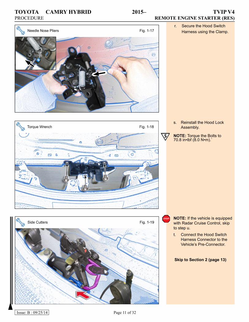
Needle Nose Pliers Fig. 1-17r. Secure the Hood Switch
Harness using the Clamp.
s. Reinstall the Hood Lock Assembly.
NOTE: Torque the Bolts to 70.8 in•lbf (8.0 N•m).`
NOTE: If the vehicle is equipped with Radar Cruise Control, skip to step u.t. Connect the Hood Switch
Harness Connector to the Vehicle’s Pre-Connector.
SkiptoSection2(page13)
TOYOTA CAMRY HYBRID 2015– TVIP V4PROCEDURE REMOTE ENGINE STARTER (RES)
Page 12 of 32Issue: B : 09/25/14
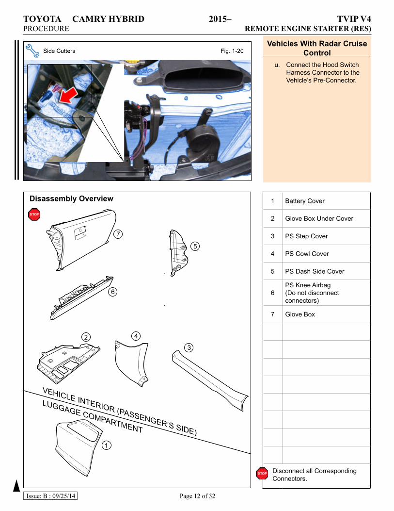
VehiclesWithRadarCruiseControl
u. Connect the Hood Switch Harness Connector to the Vehicle’s Pre-Connector.
1 Battery Cover
2 Glove Box Under Cover
3 PS Step Cover
4 PS Cowl Cover
5 PS Dash Side Cover
6PS Knee Airbag (Do not disconnect connectors)
7 Glove Box
Disconnect all Corresponding Connectors.
DisassemblyOverview
1
23
4
5
6
VEHICLE INTERIOR (PASSENGER’S SIDE)
LUGGAGE COMPARTMENT
7
TOYOTA CAMRY HYBRID 2015– TVIP V4PROCEDURE REMOTE ENGINE STARTER (RES)
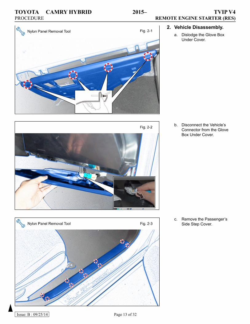
Page 13 of 32Issue: B : 09/25/14
2. VehicleDisassembly.a. Dislodge the Glove Box
Under Cover.
b. Disconnect the Vehicle’s Connector from the Glove Box Under Cover.
c. Remove the Passenger’s Side Step Cover.
TOYOTA CAMRY HYBRID 2015– TVIP V4PROCEDURE REMOTE ENGINE STARTER (RES)
Page 14 of 32Issue: B : 09/25/14
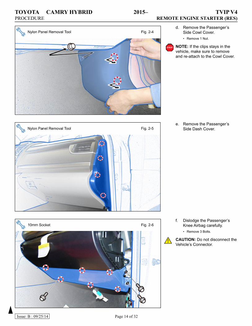
d. Remove the Passenger’s Side Cowl Cover.• Remove 1 Nut.
NOTE: If the clips stays in the vehicle, make sure to remove and re-attach to the Cowl Cover.
e. Remove the Passenger’s Side Dash Cover.
f. Dislodge the Passenger’s Knee Airbag carefully.• Remove 3 Bolts.
CAUTION: Do not disconnect the Vehicle’s Connector.
TOYOTA CAMRY HYBRID 2015– TVIP V4PROCEDURE REMOTE ENGINE STARTER (RES)
Page 15 of 32Issue: B : 09/25/14
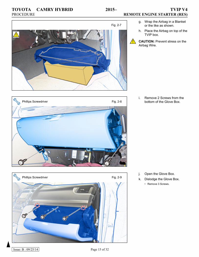
g. Wrap the Airbag in a Blanket or the like as shown.
h. Place the Airbag on top of the TVIP box.
CAUTION: Prevent stress on the Airbag Wire.
i. Remove 2 Screws from the bottom of the Glove Box.
j. Open the Glove Box.k. Dislodge the Glove Box.
• Remove 3 Screws.
TOYOTA CAMRY HYBRID 2015– TVIP V4PROCEDURE REMOTE ENGINE STARTER (RES)
Page 16 of 32Issue: B : 09/25/14
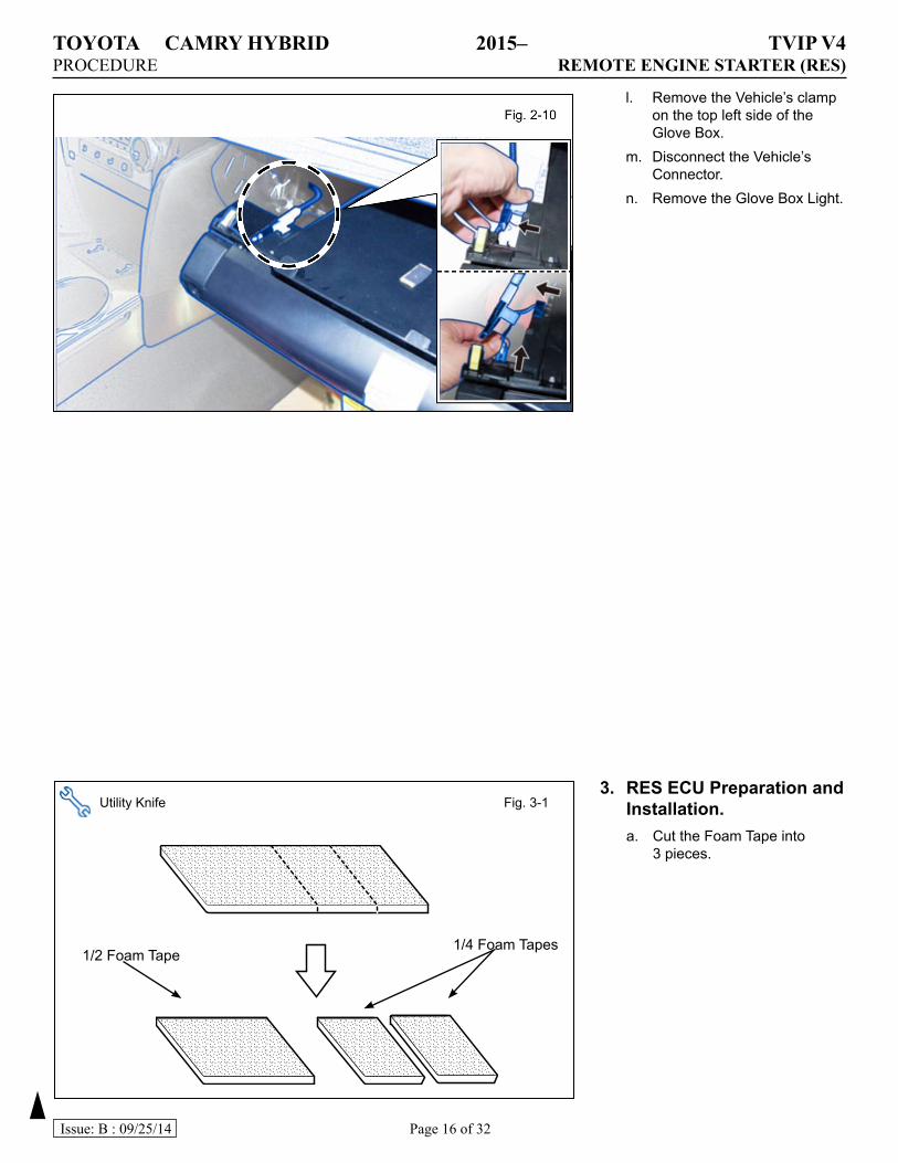
l. Remove the Vehicle’s clamp on the top left side of the Glove Box.
m. Disconnect the Vehicle’s Connector.
n. Remove the Glove Box Light.
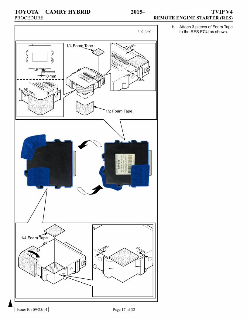
3. RESECUPreparationandInstallation.a. Cut the Foam Tape into
3 pieces.
Utility Knife Fig. 3-1
1/2 Foam Tape 1/4 Foam Tapes
TOYOTA CAMRY HYBRID 2015– TVIP V4PROCEDURE REMOTE ENGINE STARTER (RES)
Page 17 of 32Issue: B : 09/25/14
b. Attach 3 pieces of Foam Tape to the RES ECU as shown.Fig. 3-2
0 mm0 mm
0 mm
0 mm 0 mm
0 mm
0 mm
1/2 Foam Tape
1/4 Foam Tape
1/4 Foam Tape
TOYOTA CAMRY HYBRID 2015– TVIP V4PROCEDURE REMOTE ENGINE STARTER (RES)
Page 18 of 32Issue: B : 09/25/14
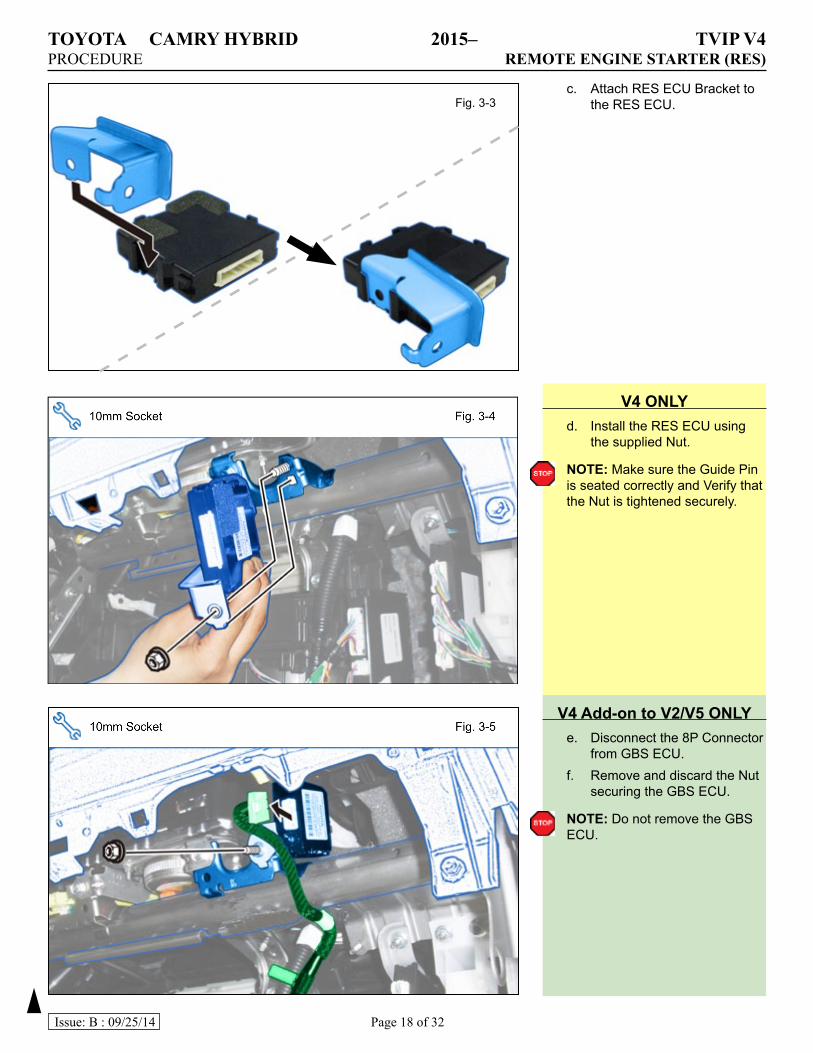
V4ONLYd. Install the RES ECU using
the supplied Nut.
NOTE: Make sure the Guide Pin is seated correctly and Verify that the Nut is tightened securely.
c. Attach RES ECU Bracket to the RES ECU.Fig. 3-3
V4Add-ontoV2/V5ONLYe. Disconnect the 8P Connector
from GBS ECU.f. Remove and discard the Nut
securing the GBS ECU.
NOTE: Do not remove the GBS ECU.
TOYOTA CAMRY HYBRID 2015– TVIP V4PROCEDURE REMOTE ENGINE STARTER (RES)
Page 19 of 32Issue: B : 09/25/14
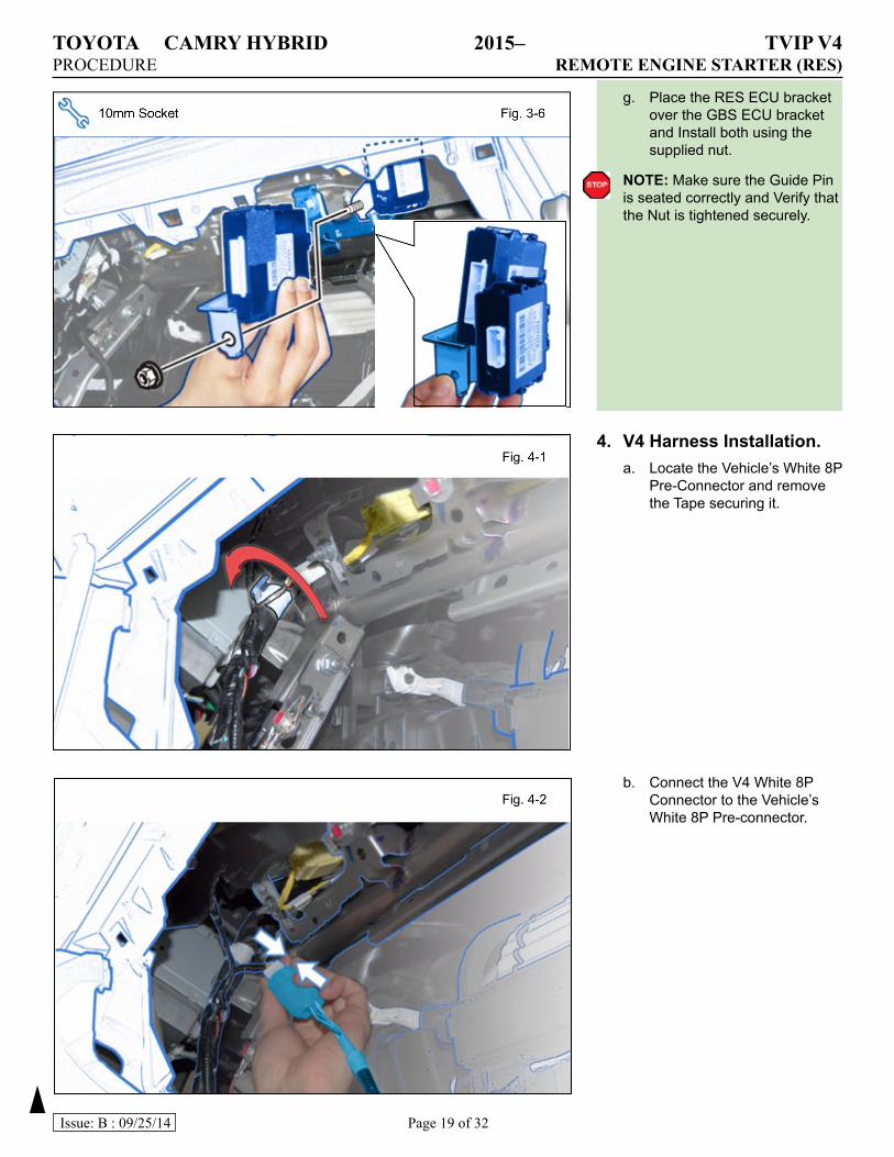
4. V4HarnessInstallation.a. Locate the Vehicle’s White 8P
Pre-Connector and remove the Tape securing it.
g. Place the RES ECU bracket over the GBS ECU bracket and Install both using the supplied nut.
NOTE: Make sure the Guide Pin is seated correctly and Verify that the Nut is tightened securely.
b. Connect the V4 White 8P Connector to the Vehicle’s White 8P Pre-connector.
TOYOTA CAMRY HYBRID 2015– TVIP V4PROCEDURE REMOTE ENGINE STARTER (RES)
Page 20 of 32Issue: B : 09/25/14
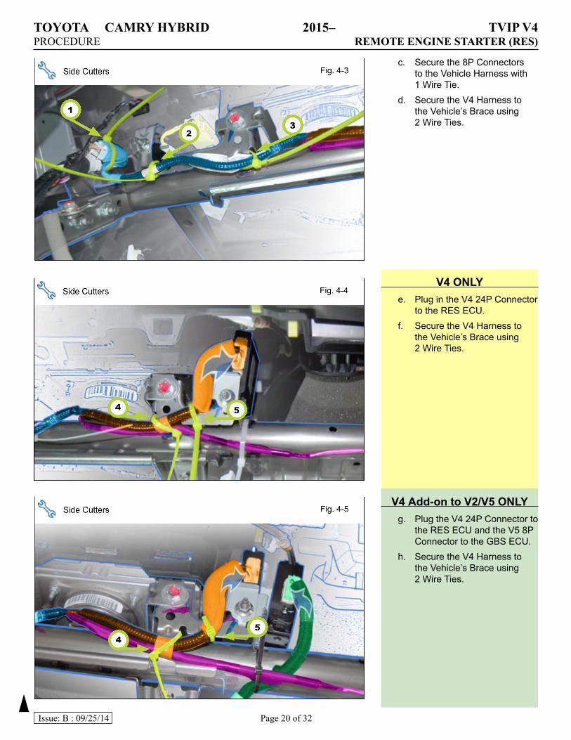
c. Secure the 8P Connectors to the Vehicle Harness with 1 Wire Tie.
d. Secure the V4 Harness to the Vehicle’s Brace using 2 Wire Ties.
V4ONLYe. Plug in the V4 24P Connector
to the RES ECU.f. Secure the V4 Harness to
the Vehicle’s Brace using 2 Wire Ties.
V4 Add-ontoV2/V5ONLYg. Plug the V4 24P Connector to
the RES ECU and the V5 8P Connector to the GBS ECU.
h. Secure the V4 Harness to the Vehicle’s Brace using 2 Wire Ties.
TOYOTA CAMRY HYBRID 2015– TVIP V4PROCEDURE REMOTE ENGINE STARTER (RES)
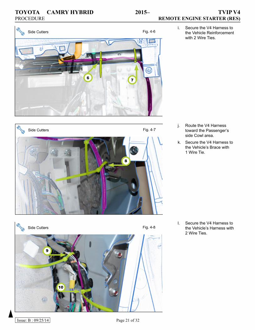
Page 21 of 32Issue: B : 09/25/14
i. Secure the V4 Harness to the Vehicle Reinforcement with 2 Wire Ties.
j. Route the V4 Harness toward the Passenger’s side Cowl area.
k. Secure the V4 Harness to the Vehicle’s Brace with 1 Wire Tie.
l. Secure the V4 Harness to the Vehicle’s Harness with 2 Wire Ties.
TOYOTA CAMRY HYBRID 2015– TVIP V4PROCEDURE REMOTE ENGINE STARTER (RES)
Page 22 of 32Issue: B : 09/25/14
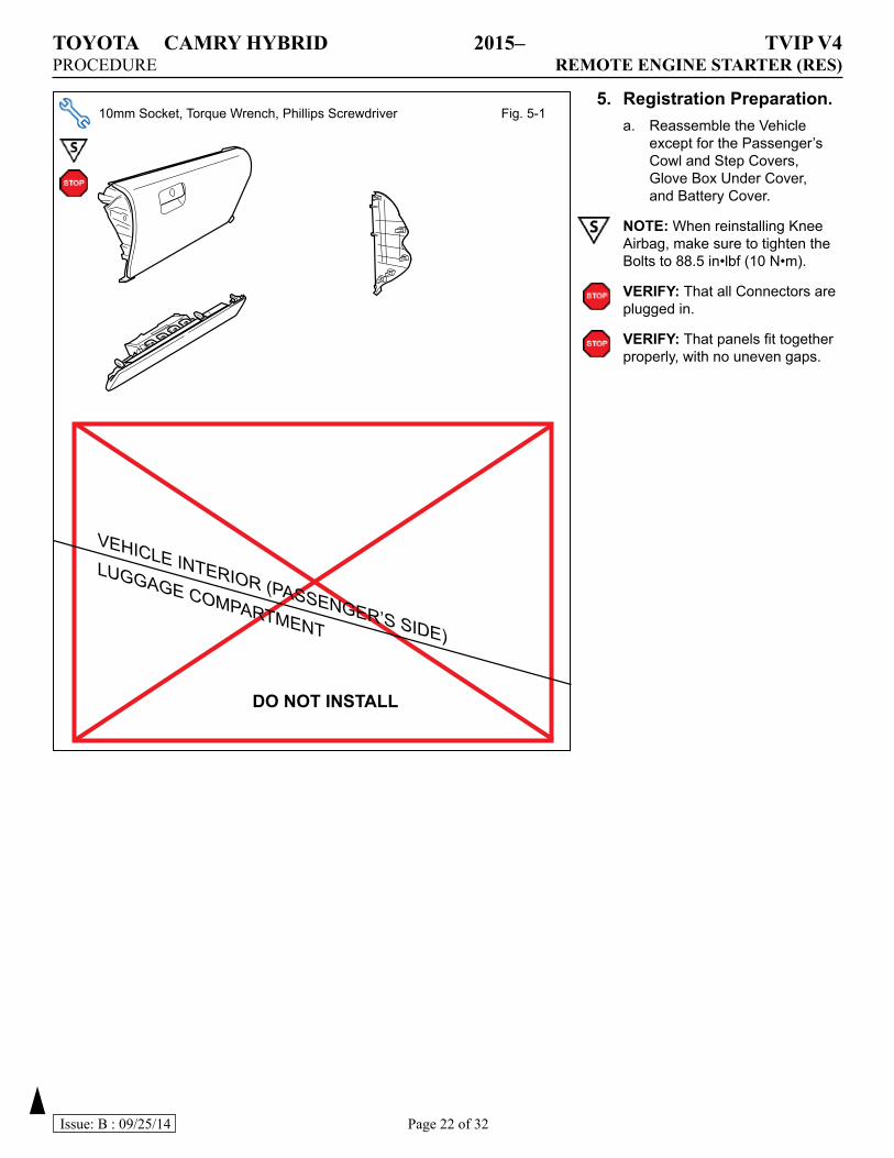
5. RegistrationPreparation.a. Reassemble the Vehicle
except for the Passenger’s Cowl and Step Covers, Glove Box Under Cover, and Battery Cover.
NOTE: When reinstalling Knee Airbag, make sure to tighten the Bolts to 88.5 in•lbf (10 N•m).
VERIFY:That all Connectors are plugged in.
VERIFY:That panels fit together properly, with no uneven gaps.
10mm Socket, Torque Wrench, Phillips Screwdriver Fig. 5-1
DO NOT INSTALL
VEHICLE INTERIOR (PASSENGER’S SIDE)
LUGGAGE COMPARTMENT
TOYOTA CAMRY HYBRID 2015– TVIP V4PROCEDURE REMOTE ENGINE STARTER (RES)
Page 23 of 32Issue: B : 09/25/14
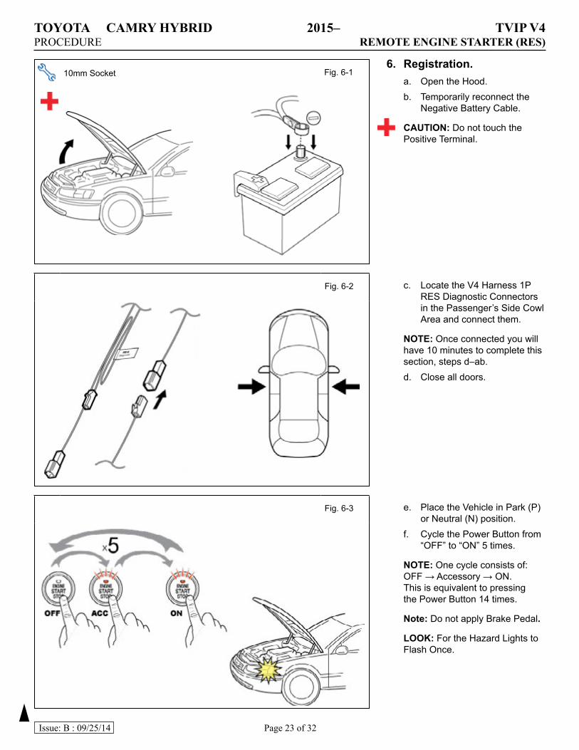
6. Registration.a. Open the Hood.b. Temporarily reconnect the
Negative Battery Cable.
CAUTION: Do not touch the Positive Terminal.
10mm Socket Fig. 6-1
e. Place the Vehicle in Park (P) or Neutral (N) position.
f. Cycle the Power Button from “OFF” to “ON” 5 times.
NOTE: One cycle consists of: OFF → Accessory → ON. This is equivalent to pressing the Power Button 14 times.
Note: Do not apply Brake Pedal.
LOOK: For the Hazard Lights to Flash Once.
Fig. 6-2 c. Locate the V4 Harness 1P RES Diagnostic Connectors in the Passenger’s Side Cowl Area and connect them.
NOTE: Once connected you will have 10 minutes to complete this section, steps d–ab.d. Close all doors.
Fig. 6-3
TOYOTA CAMRY HYBRID 2015– TVIP V4PROCEDURE REMOTE ENGINE STARTER (RES)
Page 24 of 32Issue: B : 09/25/14
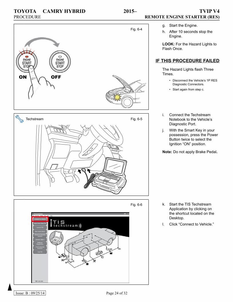
g. Start the Engine.h. After 10 seconds stop the
Engine.
LOOK: For the Hazard Lights to Flash Once.
IFTHISPROCEDUREFAILED
The Hazard Lights flash Three Times.
• Disconnect the Vehicle’s 1P RES Diagnostic Connectors.
• Start again from step c.
Fig. 6-4
i. Connect the Techstream Notebook to the Vehicle’s Diagnostic Port.
j. With the Smart Key in your possession, press the Power Button twice to select the Ignition “ON” position.
Note: Do not apply Brake Pedal.
k. Start the TIS Techstream Application by clicking on the shortcut located on the Desktop.
l. Click “Connect to Vehicle.”
Techstream Fig. 6-5
Fig. 6-6
TOYOTA CAMRY HYBRID 2015– TVIP V4PROCEDURE REMOTE ENGINE STARTER (RES)
Page 25 of 32Issue: B : 09/25/14
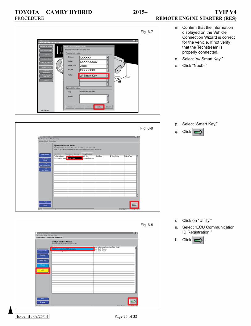
m. Confirm that the information displayed on the Vehicle Connection Wizard is correct for the vehicle. If not verify that the Techstream is properly connected.
n. Select “w/ Smart Key.”o. Click “Next>.”
r. Click on “Utility.”s. Select “ECU Communication
ID Registration.”
t. Click .
p. Select “Smart Key.”
q. Click .
File Function Setup TIS User Help
Connect to Vehicle
Open Scan Data File
Launch TIS
New Users Demo
Generic OBD II
Log Out
SoftwareRegistration
Check for ScantoolUpdates
User/LanguageSelection
Ver x.xx.xxx
TISt e c h s t r e a m
A B S
TIS techstream
Vehicle Connection Wizard(S301-04)
Select the Information and press Next
Required Information:
Optional Information:
VIN:
Memo:
xxxxxxxxxxxxxxxxxxx
Division: XXXXXXModel: XXXXXXXXXModel Year: 20XXEngine:
Option:
XXXXXXXX
w/ Smart Key
CancelNext><BackHelpManual
Fig. 6-7
TIS techstream - 10645
File Function Setup TIS User Help
System Select
System Selection Menu
Stored Data
Health Check
CustomizeSetting
ECUReprogramming
CANBus. Check
Close
Generic EnglishS601-03 DLC3
Air ConditionerCombination Meter *Sliding Roof
SRS Airbag Main Body Tilt&Telescopic
Main Body *Accessory Gateway Combination Meter
Back Door *Driver Door Mirror
D Door Motor *Passenger Door Occupant Detection
Sliding Roof Driver Seat
TIS techstream - 10645
File Function Setup TIS User Help
System Select
System Selection MenuSelect desired system and then press Live Data to access the ECU.Note: An astr isk (*) indicates a system that is unsupported or not responding.
Stored Data
All ECUs Powertrain Chassis Body Electrical
Health Check
CustomizeSetting
ECUReprogramming
CANBus. Check
Close
Generic EnglishS601-03 DLC3
Air ConditionerCombination Meter
SRS AirbagSmart Key
Main BodyOccupant Detection
Back Door D Door Motor Sliding Roof
Fig. 6-8
TIS techstream - 10645
File Function Setup TIS User Help
System Select
Utility Selection Menue
Stored Data Customize
Close Generic EnglishS601-03 DLC3
CustimizeECU Communication ID RegistrationSmart Code Registration
Communication Check(Key Diag Mode)Smart Code ErasureSmart Code ResetTrouble Codes
Data List
Active Test
Monitor
Utility
Select desired Utility and then press Next button.
Fig. 6-9
TOYOTA CAMRY HYBRID 2015– TVIP V4PROCEDURE REMOTE ENGINE STARTER (RES)
Page 26 of 32Issue: B : 09/25/14
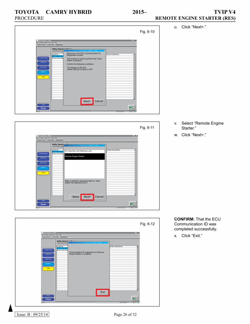
u. Click “Next>.”
CONFIRM:That the ECU Communication ID was completed successfully.x. Click “Exit.”
v. Select “Remote Engine Starter.”
w. Click “Next>.”
TIS techstream - 10645
File Function Setup TIS User Help
System Select
Utility Selection Menue
Stored Data Customize
Close Generic EnglishS601-03 DLC3
CustimizeECU Communication ID RegistrationSmart Code Registration
Communication Check(Key Diag Mode)Smart Code ErasureSmart Code ResetTrouble Codes
Data List
Active Test
Monitor
Utility
Select desired Utility and then press Next button. ECU Communication ID Registration (SMRT-13-001)
Welcome to the ECU Communication ID Registration wizard.
This function is used to perform the “hand shake” procedure.
Confirm the following conditions:
-The Engine is ON (IG)-Smart Cancel Function is OFF
CancelNext>
Fig. 6-10
TIS techstream - 10645
File Function Setup TIS User Help
System Select
Utility Selection Menue
Stored Data Customize
Close Generic EnglishS601-03 DLC3
CustimizeECU Communication ID RegistrationSmart Code Registration
Communication Check(Key Diag Mode)Smart Code ErasureSmart Code ResetTrouble Codes
Data List
Active Test
Monitor
Utility
Select desired Utility and then press Next button. ECU Communication ID Registration (SMRT-13-002)
Make a selection and press Next to “hand shake” the selected ECU’s
CancelNext><Back
ID Code Box and Steering Lock
Remote Engine Starter
Fig. 6-11
TIS techstream - 10645
File Function Setup TIS User Help
System Select
Utility Selection Menue
Stored Data Customize
Close Generic EnglishS601-03 DLC3
CustimizeECU Communication ID RegistrationSmart Code Registration
Communication Check(Key Diag Mode)Smart Code ErasureSmart Code ResetTrouble Codes
Data List
Active Test
Monitor
Utility
Select desired Utility and then press Next button. ECU Communication ID Registration (SMRT-13-002)
Communication ID registration for Remote Engine Starter is complete.
Exit
Fig. 6-12
TOYOTA CAMRY HYBRID 2015– TVIP V4PROCEDURE REMOTE ENGINE STARTER (RES)
Page 27 of 32Issue: B : 09/25/14
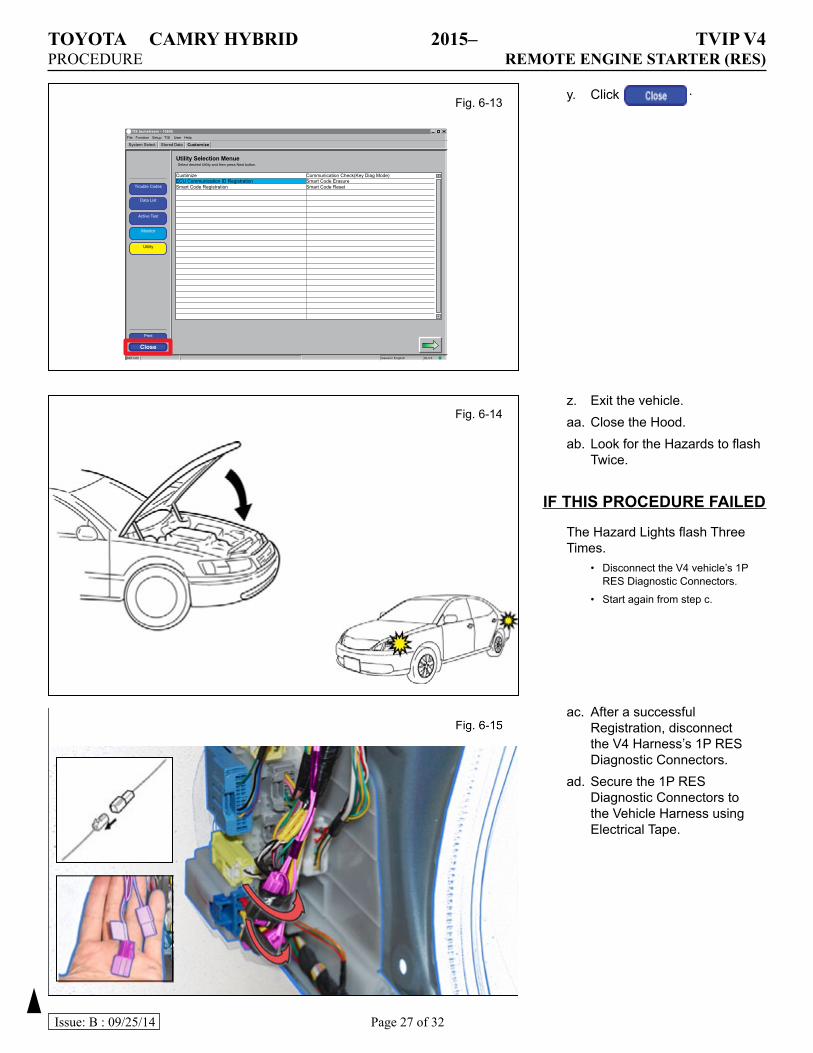
y. Click .
Fig. 6-14z. Exit the vehicle.aa. Close the Hood.ab. Look for the Hazards to flash
Twice.
IFTHISPROCEDUREFAILED
The Hazard Lights flash Three Times.
• Disconnect the V4 vehicle’s 1P RES Diagnostic Connectors.
• Start again from step c.
ac. After a successful Registration, disconnect the V4 Harness’s 1P RES Diagnostic Connectors.
ad. Secure the 1P RES Diagnostic Connectors to the Vehicle Harness using Electrical Tape.
TIS techstream - 10645
File Function Setup TIS User Help
System Select
Utility Selection Menue
Stored Data Customize
Close Generic EnglishS601-03 DLC3
CustimizeECU Communication ID RegistrationSmart Code Registration
Communication Check(Key Diag Mode)Smart Code ErasureSmart Code ResetTrouble Codes
Data List
Active Test
Monitor
Utility
Select desired Utility and then press Next button.
Fig. 6-13
TOYOTA CAMRY HYBRID 2015– TVIP V4PROCEDURE REMOTE ENGINE STARTER (RES)
Page 28 of 32Issue: B : 09/25/14
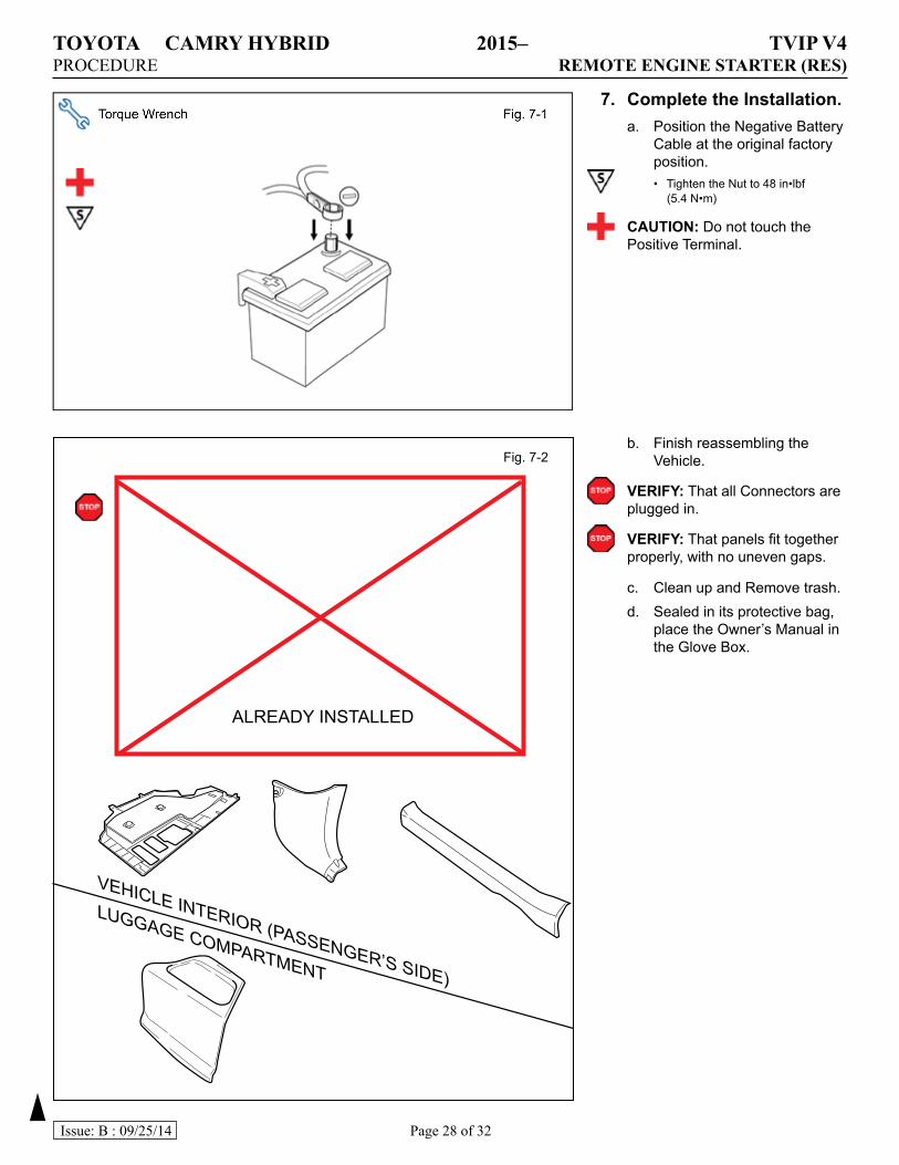
7. CompletetheInstallation.a. Position the Negative Battery
Cable at the original factory position.• Tighten the Nut to 48 in•lbf
(5.4 N•m)
CAUTION: Do not touch the Positive Terminal.
b. Finish reassembling the Vehicle.
VERIFY: That all Connectors are plugged in.
VERIFY: That panels fit together properly, with no uneven gaps.
c. Clean up and Remove trash.d. Sealed in its protective bag,
place the Owner’s Manual in the Glove Box.
Fig. 7-2
ALREADY INSTALLED
VEHICLE INTERIOR (PASSENGER’S SIDE)
LUGGAGE COMPARTMENT
TOYOTA CAMRY HYBRID 2015– TVIP V4PROCEDURE REMOTE ENGINE STARTER (RES)
Page 29 of 32Issue: B : 09/25/14
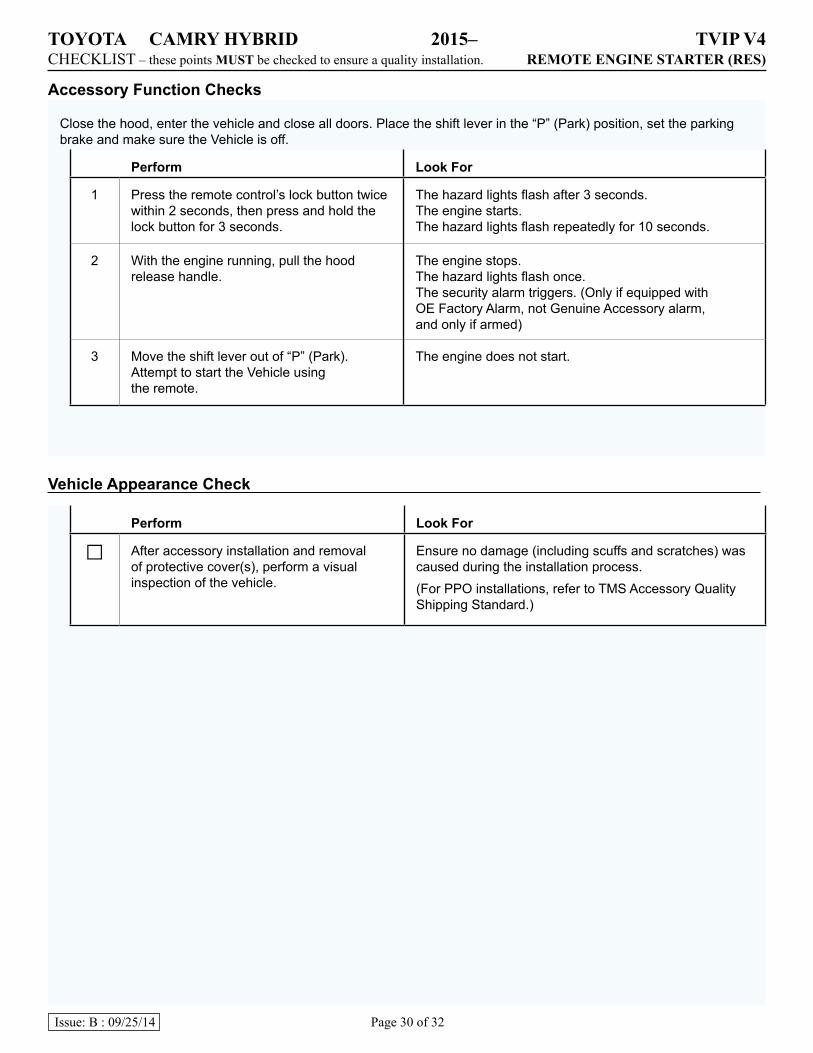
c. Using VDC approved cleaner and cleaning method, clean the indicated area on the key.
d. Use a piece of Clear Tape to lift the label off its protective backing.
CAUTION: Do not touch the adhesive surface.e. Attach the Key Label as
shown.f. Attach the Key Tag.
REPEAT: steps c–f with the otherKey.
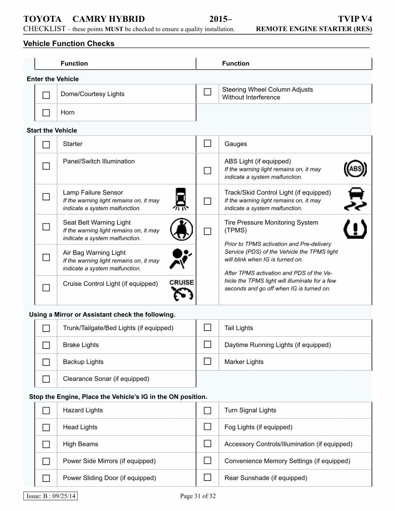
g. Use Household Glass Cleaner to clean the inside of the Front Door Windows.
h. Use a piece of Clear Tape to lift the Label off its protective backing.
CAUTION: Do not touch the adhesive surface.i. Attach the Label as shown.
NOTE: Make sure to Align label according to Etching or Other Label.
REPEAT: steps g-i with the other Window.
Clear Tape Fig. 8-2
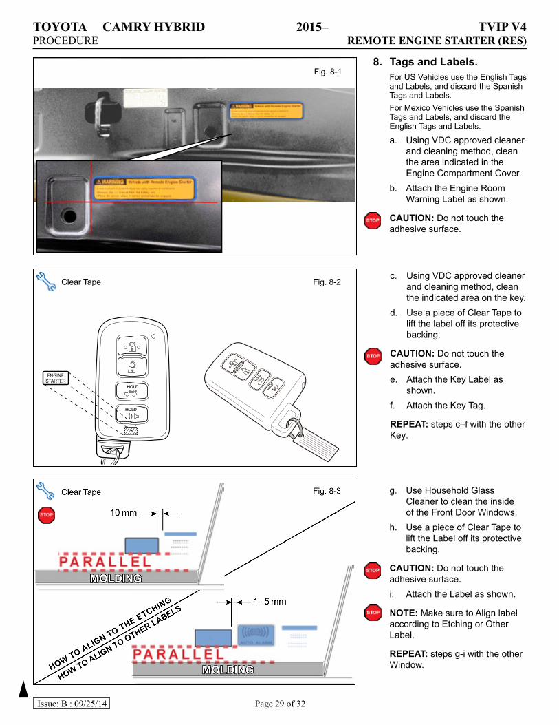
8. TagsandLabels.For US Vehicles use the English Tags and Labels, and discard the Spanish Tags and Labels.For Mexico Vehicles use the Spanish Tags and Labels, and discard the English Tags and Labels.
a. Using VDC approved cleaner and cleaning method, clean the area indicated in the Engine Compartment Cover.
b. Attach the Engine Room Warning Label as shown.
CAUTION: Do not touch the adhesive surface.
Fig. 8-1
TOYOTA CAMRY HYBRID 2015– TVIP V4CHECKLIST – these points MUST be checked to ensure a quality installation. REMOTE ENGINE STARTER (RES)
Page 30 of 32Issue: B : 09/25/14
AccessoryFunctionChecks
Close the hood, enter the vehicle and close all doors. Place the shift lever in the “P” (Park) position, set the parking brake and make sure the Vehicle is off.
Perform LookFor
1 Press the remote control’s lock button twice within 2 seconds, then press and hold the lock button for 3 seconds.
The hazard lights flash after 3 seconds. The engine starts. The hazard lights flash repeatedly for 10 seconds.
2 With the engine running, pull the hood release handle.
The engine stops. The hazard lights flash once. The security alarm triggers. (Only if equipped with OE Factory Alarm, not Genuine Accessory alarm, and only if armed)
3 Move the shift lever out of “P” (Park). Attempt to start the Vehicle using the remote.
The engine does not start.
VehicleAppearanceCheck
Perform LookFor
□ After accessory installation and removal of protective cover(s), perform a visual inspection of the vehicle.
Ensure no damage (including scuffs and scratches) was caused during the installation process.(For PPO installations, refer to TMS Accessory Quality Shipping Standard.)
TOYOTA CAMRY HYBRID 2015– TVIP V4CHECKLIST – these points MUST be checked to ensure a quality installation. REMOTE ENGINE STARTER (RES)
Page 31 of 32Issue: B : 09/25/14
VehicleFunctionChecks
Function Function
EntertheVehicle
□ Dome/Courtesy Lights □ Steering Wheel Column Adjusts Without Interference
□ Horn
StarttheVehicle
□ Starter □ Gauges
□ Panel/Switch Illumination
□ABS Light (if equipped) If the warning light remains on, it may indicate a system malfunction.
□ Lamp Failure Sensor If the warning light remains on, it may indicate a system malfunction.
□ Track/Skid Control Light (if equipped) If the warning light remains on, it may indicate a system malfunction.
□ Seat Belt Warning Light If the warning light remains on, it may indicate a system malfunction.
□ Tire Pressure Monitoring System (TPMS)
Prior to TPMS activation and Pre-delivery Service (PDS) of the Vehicle the TPMS light will blink when IG is turned on.
After TPMS activation and PDS of the Ve-hicle the TPMS light will illuminate for a few seconds and go off when IG is turned on.
□ Air Bag Warning Light If the warning light remains on, it may indicate a system malfunction.
□ Cruise Control Light (if equipped)
UsingaMirrororAssistantcheckthefollowing.
□ Trunk/Tailgate/Bed Lights (if equipped) □ Tail Lights
□ Brake Lights □ Daytime Running Lights (if equipped)
□ Backup Lights □ Marker Lights
□ Clearance Sonar (if equipped)
StoptheEngine,PlacetheVehicle’sIGintheONposition.
□ Hazard Lights □ Turn Signal Lights
□ Head Lights □ Fog Lights (if equipped)
□ High Beams □ Accessory Controls/Illumination (if equipped)
□ Power Side Mirrors (if equipped) □ Convenience Memory Settings (if equipped)
□ Power Sliding Door (if equipped) □ Rear Sunshade (if equipped)
TOYOTA CAMRY HYBRID 2015– TVIP V4CHECKLIST – these points MUST be checked to ensure a quality installation. REMOTE ENGINE STARTER (RES)
Page 32 of 32Issue: B : 09/25/14
Function Function
□ Front Wiper/Washer □ Rear Wiper/Washer (if equipped)
□ Power Sun/Moon Roof (if equipped) □ Rollover Side Curtain Air Bag Switch (RSCA) (if equipped)
□ Clock (if equipped) □ Navigation System (if equipped)
□ Audio/Video (if equipped) □ USB Connections (if equipped)
□ Steering Wheel Audio Control (if equipped) □ HVAC
□ Front Windshield Defogger (if equipped) □ Rear Window Defogger (if equipped)
□ Side Mirror Defogger (if equipped) □ Accessory Power Socket (if equipped)
□ Massage Seats (if equipped) □ Heated/Vented Seats (if equipped)
□ Glove Box Light (if equipped) □ Passenger Air Bag Switch (if equipped)
□ Power Locks (if equipped) □ Power Windows (if equipped)
□ Power Seats (if equipped) □ Key Sensor Buzzer


![Toyota Innova Brochure [toyota-solo.com]](https://img.pdfslide.net/doc/110x75/552a55904a7959286e8b45c5/toyota-innova-brochure-toyota-solocom.jpg)