Embed Size (px)
Citation preview
TP 08-02 Revision 0
Page 1 of 24
IMPORTANT NOTICE: The current official version of this document is available via the Sandia National Laboratories WIPP Online Documents web site. A printed copy of this document may not be the version currently in effect.
Sandia National Laboratories Waste Isolation Pilot Plant (WIPP)
Test Plan (TP)
Iron, Lead, Sulfide, and EDTA Solubilities, Test Plan TP 08-02
Rev. 0
Effective Date: 03/25/08
Prepared by: Ahmed E. Ismail Martin B. Nemer
Performance Assessment, Org. 6711 Sandia National Laboratories
Carlsbad, NM
Gregory T. Roselle Yongliang Xiong
Repository Performance, Org. 6712 Sandia National Laboratories
Carlsbad, NM
© 2008 Sandia Corporation
TP 08-02 Revision 0
Page 2 of 24
APPROVAL PAGE
Authors: Original signed by Ahmed E. Ismail
3/25/2008
Ahmed E. Ismail (6711) Date
Original signed by Martin Nemer
3/25/2008
Martin B. Nemer (6711) Date
Original signed by
Christi Leigh for Greg Roselle
3/25/08
Gregory T. Roselle (6712) Date
Original signed by Yongliang Xiong
03/25/2008 Yongliang Xiong (6712) Date
Technical Reviewer:
Original signed by Ahmed E. Ismail for Tom Wolery
3/25/2008
Tom Wolery (LLNL) Date
ES&H Reviewer: Original signed by Ronald T. Parsons 3/25/08 Ronald T. Parsons (6710) Date
QA Reviewer : Original signed by Douglas R. Edmiston
3/25/08
Doug Edmiston (6710) Date
Management Reviewer: Original signed by Christi Leigh
3/25/08
Christi D. Leigh (6712) Date
TP 08-02 Revision 0
Page 3 of 24
TABLE OF CONTENTS
LIST OF TABLES...........................................................................................................................5
DEFINITION OF ABBREVIATIONS AND ACRONYMS, AND INITIALISMS.......................6
REVISION HISTORY.....................................................................................................................8
1 PURPOSE AND SCOPE..............................................................................................................9
2 EXPERIMENTAL PROCESS DESCRIPTION.........................................................................10
2.1 Task List ..................................................................................................................10
2.1.1 Task 1: Determine Systems to be Studied ........................................................10 2.1.2 Task 2: Sample Preparation ..............................................................................12 2.1.3 Task 3: Testing for Equilibrium........................................................................15 2.1.4 Task 4: Characterization of Equilibrated Samples............................................15 2.1.5 Task 5: Measurement of EDTA Solubilities.....................................................15
2.2 Experimental Procedures to be Used or Developed ................................................15
2.2.1 General Procedures ...........................................................................................15 2.2.2 Solution Preparation..........................................................................................16 2.2.3 Redox Control ...................................................................................................16 2.2.4 Determination of Concentrations ......................................................................16
2.3 Coordination with Organizations Providing Inputs or Using the Results ...............16 2.4 Sources of Uncertainty.............................................................................................17
3 SAMPLE CONTROL.................................................................................................................18
4 DATA QUALITY CONTROL...................................................................................................19
4.1 Measuring and Test Equipment (M&TE)................................................................19 4.2 Data Acquisition Plan ..............................................................................................19 4.3 Data Qualification....................................................................................................19
5 EQUIPMENT .............................................................................................................................20
5.1 Weighing Equipment ...............................................................................................20 5.2 Temperature Measuring Equipment ........................................................................20 5.3 Volumetric Measuring Equipment...........................................................................20 5.4 Other Analytical Equipment ....................................................................................20

TP 08-02 Revision 0
Page 4 of 24
6 TRAINING .................................................................................................................................21
7 HEALTH AND SAFETY...........................................................................................................22
8 PERMITTING/LICENSING ......................................................................................................23
9 REFERENCES ...........................................................................................................................24

TP 08-02 Revision 0
Page 5 of 24
LIST OF TABLES
Table 1. Abbreviations, Acronyms, and Initialisms. .......................................................................6
Table 2. Potential Pitzer Parameters to be Measured ....................................................................10
Table 3. Solutions, Controlling Phases and Schedule for Completion ..........................................13
TP 08-02 Revision 0
Page 6 of 24
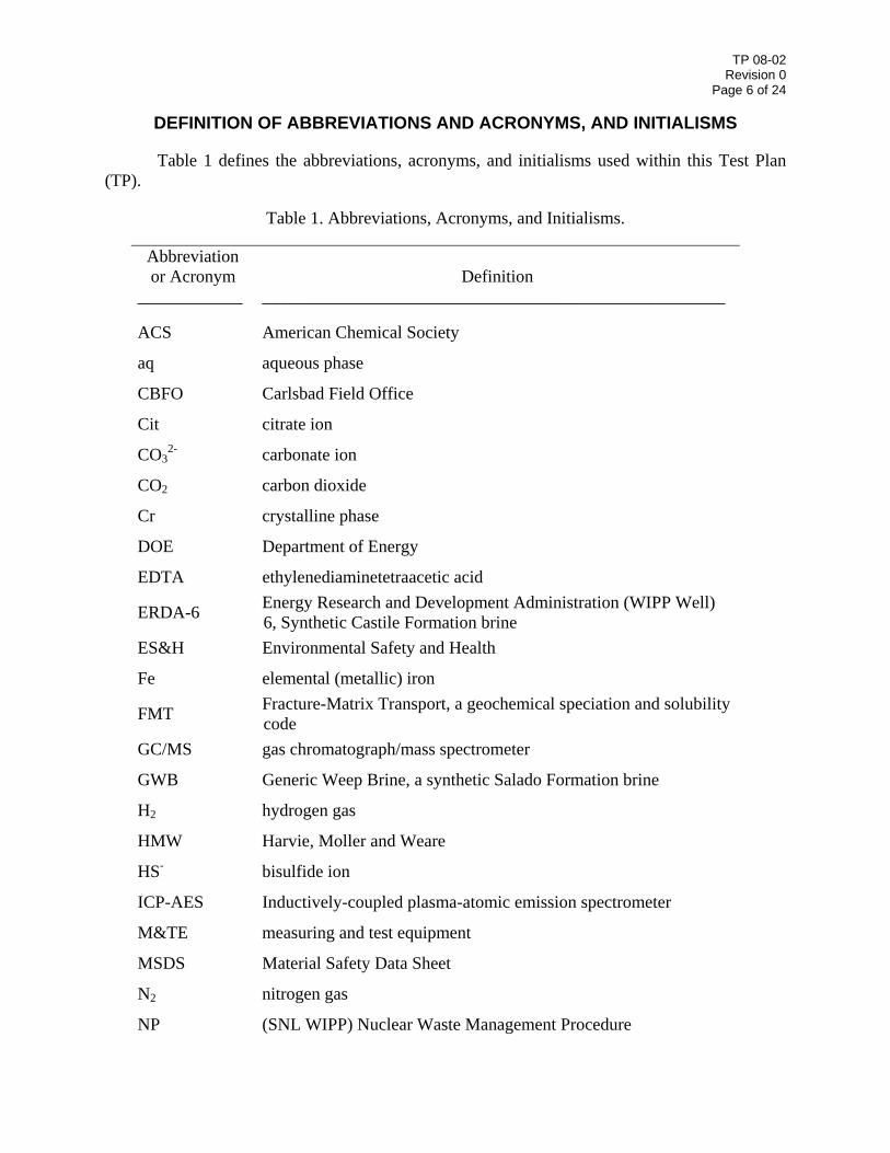
DEFINITION OF ABBREVIATIONS AND ACRONYMS, AND INITIALISMS
Table 1 defines the abbreviations, acronyms, and initialisms used within this Test Plan (TP).
Table 1. Abbreviations, Acronyms, and Initialisms.
Abbreviation or Acronym
Definition
____________ _____________________________________________________
ACS American Chemical Society
aq aqueous phase
CBFO Carlsbad Field Office
Cit citrate ion
CO32- carbonate ion
CO2 carbon dioxide
Cr crystalline phase
DOE Department of Energy
EDTA ethylenediaminetetraacetic acid
ERDA-6 Energy Research and Development Administration (WIPP Well) 6, Synthetic Castile Formation brine
ES&H Environmental Safety and Health
Fe elemental (metallic) iron
FMT Fracture-Matrix Transport, a geochemical speciation and solubility code
GC/MS gas chromatograph/mass spectrometer
GWB Generic Weep Brine, a synthetic Salado Formation brine
H2 hydrogen gas
HMW Harvie, Moller and Weare
HS- bisulfide ion
ICP-AES Inductively-coupled plasma-atomic emission spectrometer
M&TE measuring and test equipment
MSDS Material Safety Data Sheet
N2 nitrogen gas
NP (SNL WIPP) Nuclear Waste Management Procedure
TP 08-02 Revision 0
Page 7 of 24
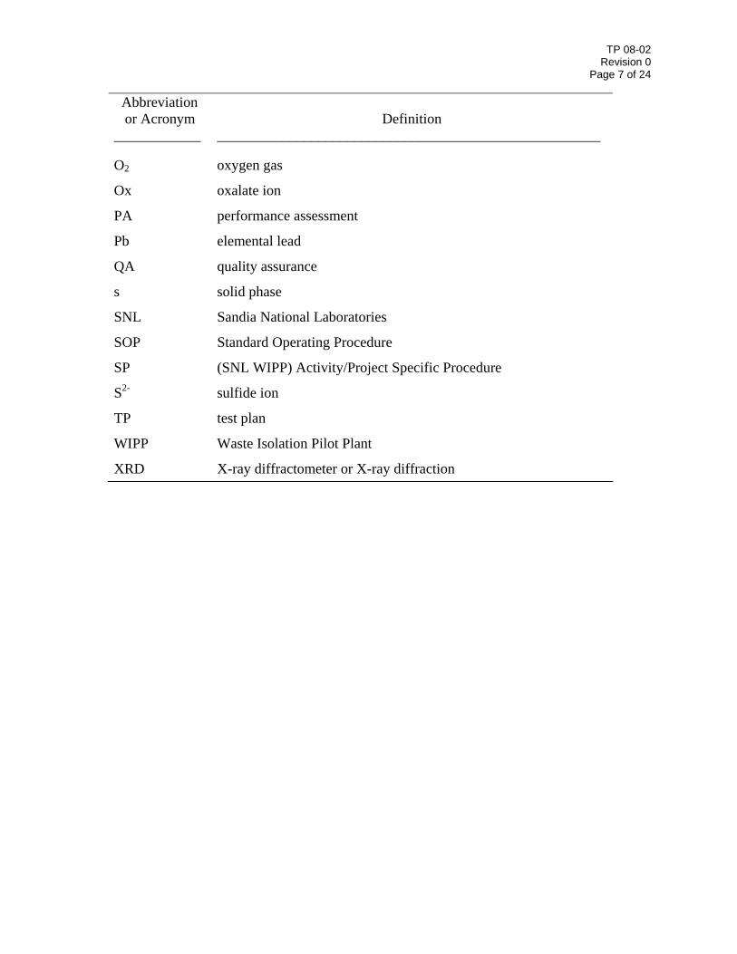
Abbreviation or Acronym
Definition
____________ _____________________________________________________
O2 oxygen gas
Ox oxalate ion
PA performance assessment
Pb elemental lead
QA quality assurance
s solid phase
SNL Sandia National Laboratories
SOP Standard Operating Procedure
SP (SNL WIPP) Activity/Project Specific Procedure
S2- sulfide ion
TP test plan
WIPP Waste Isolation Pilot Plant
XRD X-ray diffractometer or X-ray diffraction

TP 08-02 Revision 0
Page 8 of 24
REVISION HISTORY
This is the original version of this test plan. Revisions to this test plan will be prepared in accordance with the following Sandia Na-
tional Laboratories (SNL) Waste Isolation Pilot Plant (WIPP) Nuclear Waste Management Pro-cedures: NP 6-1, NP 6-2, and NP 20-1 (Subsection 2.5).
TP 08-02 Revision 0
Page 9 of 24
1 PURPOSE AND SCOPE
To determine the solution chemistry for brines within the WIPP repository, WIPP PA uses the Pitzer methodology to evaluate the activity coefficients for the various components of the brine. To date, our Pitzer thermodynamic database (Harvie, Moller, and Weare 1984) does not incorporate any phase or aqueous species that includes either iron or lead. While the HMW model does include sulfur, it does so only in the form of sulfate and omits more reduced forms of sulfur such as sulfide and bisulfide ions. This database is most often used by aqueous speciation codes, such as EQ3/6 and FMT, which calculate the actinide solubilities under expected WIPP conditions. There are significant amounts of iron present in the repository as a result of the steel used in the waste containers; in addition, the proposed change to allow shielded containers in the repository has the potential to increase greatly the amount of lead that will be present in the re-pository. Consequently, it is important to measure the solubilities of the expected and experimen-tally-observed iron and lead bearing phases. In addition, since many of the important interactions with iron and lead involve sulfide species, it will be necessary to characterize several additional parameters for sulfide species as well. Since literature data is not available for these quantities, experimental work is required to determine their values.
The purpose of the experimental work described in this test plan is to measure the solu-
bilities of pairs of ions including iron (Fe), lead (Pb), and sulfide (HS-) that we expect to be pre-sent in the WIPP repository. These solubilities will be used to develop Pitzer parameters that will then be incorporated into the WIPP thermodynamic database. Our methodology will be to meas-ure the solubilities of ions or complexes of interest as a function of ionic strength of the solution. The results will then be fit to Pitzer’s activity coefficient model to determine what are known as Pitzer parameters (Pitzer 1973; Pitzer 1991). To accomplish this simple brine solutions (such as sodium chloride or magnesium chloride) are created as the matrix solution and then pairs or trip-lets of ions to be studied are added. This is performed at various concentrations, ionic strengths, and pH values, in order to obtain a good fit to Pitzer’s model. Parameters such as pH and satura-tion are also varied to approach equilibrium from multiple directions to demonstrate that solu-tions have actually reached equilibrium. After the systems have reached equilibrium, the concentrations of the species of interest in the brine are quantitatively measured. In addition, for systems containing iron, concentrations of Fe(II) and Fe(III) will be determined.
The work proposed in this document can be loosely broken down into three main stages.
After determining that a particular system needs to be characterized, the first stage will involve the preparation of the samples needed to determine the equilibrium concentrations of the various components involved. The second stage will require monitoring of the samples to check if equilibration is complete; this will require a period of several weeks to several months, depend-ing upon the specific components being analyzed. We will approach the equilibrium state from both under- and over-saturation to ensure that the equilibrium state is properly bracketed. Fol-lowing equilibration, analysis of the dissolved species in the various samples for a given system will determine the concentrations of the species needed to determine the Pitzer parameters for a given pair or triple of ions.
Once complete, the results of this study will provide an improved model for the solution
thermodynamics in the WIPP repository, as we will be able to incorporate Fe(II), lead, and sul-fide into our thermodynamic database.
TP 08-02 Revision 0
Page 10 of 24
2 EXPERIMENTAL PROCESS DESCRIPTION
2.1 Task List
2.1.1 Task 1: Determine Systems to be Studied
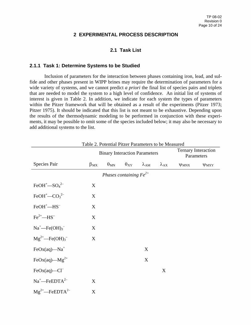
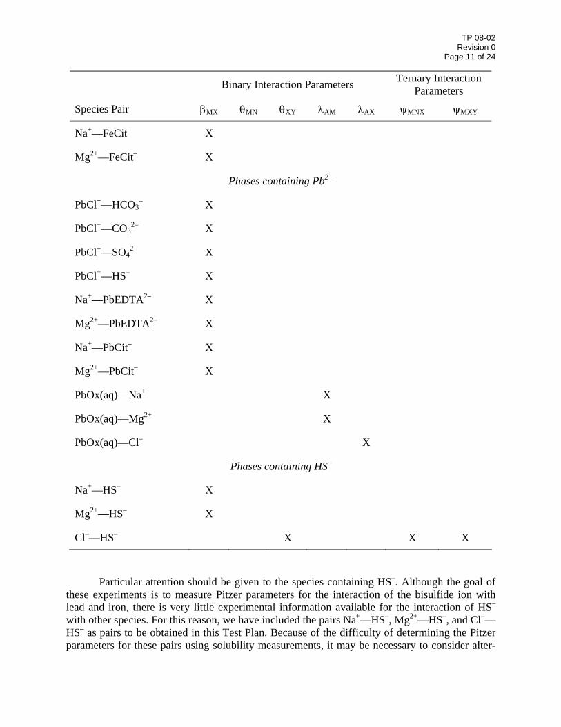
Inclusion of parameters for the interaction between phases containing iron, lead, and sul-fide and other phases present in WIPP brines may require the determination of parameters for a wide variety of systems, and we cannot predict a priori the final list of species pairs and triplets that are needed to model the system to a high level of confidence. An initial list of systems of interest is given in Table 2. In addition, we indicate for each system the types of parameters within the Pitzer framework that will be obtained as a result of the experiments (Pitzer 1973; Pitzer 1975). It should be indicated that this list is not meant to be exhaustive. Depending upon the results of the thermodynamic modeling to be performed in conjunction with these experi-ments, it may be possible to omit some of the species included below; it may also be necessary to add additional systems to the list.
Table 2. Potential Pitzer Parameters to be Measured
Binary Interaction Parameters Ternary Interaction Parameters
Species Pair βMX θMN θXY λAM λAX ψMNX ψMXY
Phases containing Fe2+
FeOH+—SO42– X
FeOH+—CO32– X
FeOH+—HS– X
Fe2+—HS– X
Na+—Fe(OH)3– X
Mg2+—Fe(OH)3– X
FeOx(aq)—Na+ X
FeOx(aq)—Mg2+ X
FeOx(aq)—Cl– X
Na+—FeEDTA2– X
Mg2+—FeEDTA2– X
TP 08-02 Revision 0
Page 11 of 24
Binary Interaction Parameters Ternary Interaction Parameters
Species Pair βMX θMN θXY λAM λAX ψMNX ψMXY
Na+—FeCit– X
Mg2+—FeCit– X
Phases containing Pb2+
PbCl+—HCO3– X
PbCl+—CO32– X
PbCl+—SO42– X
PbCl+—HS– X
Na+—PbEDTA2– X
Mg2+—PbEDTA2– X
Na+—PbCit– X
Mg2+—PbCit– X
PbOx(aq)—Na+ X
PbOx(aq)—Mg2+ X
PbOx(aq)—Cl– X
Phases containing HS–
Na+—HS– X
Mg2+—HS– X
Cl–—HS– X X X
Particular attention should be given to the species containing HS–. Although the goal of these experiments is to measure Pitzer parameters for the interaction of the bisulfide ion with lead and iron, there is very little experimental information available for the interaction of HS– with other species. For this reason, we have included the pairs Na+—HS–, Mg2+—HS–, and Cl–—HS– as pairs to be obtained in this Test Plan. Because of the difficulty of determining the Pitzer parameters for these pairs using solubility measurements, it may be necessary to consider alter-
TP 08-02 Revision 0
Page 12 of 24
native approaches, including (but not limited to) isopiestic experiments, HS– electrodes, relative humidity measurements, analogue approaches, and GC/MS measurements.
2.1.2 Task 2: Sample Preparation
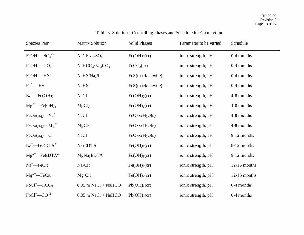
For each of the systems to be studied, a matrix of samples will be created, with at least two replicates per set of conditions tested. The different samples will have varied ionic strengths and common ions. In addition, to ensure that the equilibrium solution is “bracketed,” samples will be tested at pH’s above and below the expected equilibrium point. These pH values will ex-tend significantly above and below the envelope of pH values expected within the WIPP reposi-tory (pH values between 8.5 and 9.0); the extended range, which will include pH conditions from mildly acidic (pH ~4) to mildly alkaline (pH ~12), is necessary to ensure that the range of inter-est is properly characterized. The pH will be varied by adding appropriate amounts of acid or bases to the solutions. A table of initial matrix solutions and parameters to be varied is given be-low in Table 3 with a schedule of anticipated start and completion dates. Note that the matrix so-lution and solid phases are used to produce the species pairs listed in the left-hand column.
All solutions will be prepared in serum bottles that can be well-closed to prevent evapora-
tion of their contents. As discussed below in Subsection 2.2.3 , iron samples will be prepared in sealed serum bottles. For strongly alkaline solutions in glass bottles, we will treat the interior of the glass bottles with a resin (epoxy, for example) or by silanization, if required to prevent sam-ple interaction with the glass (Altmaier et al., 2003). In addition, redox reactions will be con-trolled as needed (see Subsection 2.2.3 for more details).
The simple brines created for testing will use common, commercially available, reagent-
grade salts such as NaCl, MgCl2, and K2SO4. The specific salts used for a given system will de-pend upon the specific ions to be studied; more than one salt or set of salts may be used for a given experiment listed in Table 3.
TP 08-02 Revision 0
Page 13 of 24
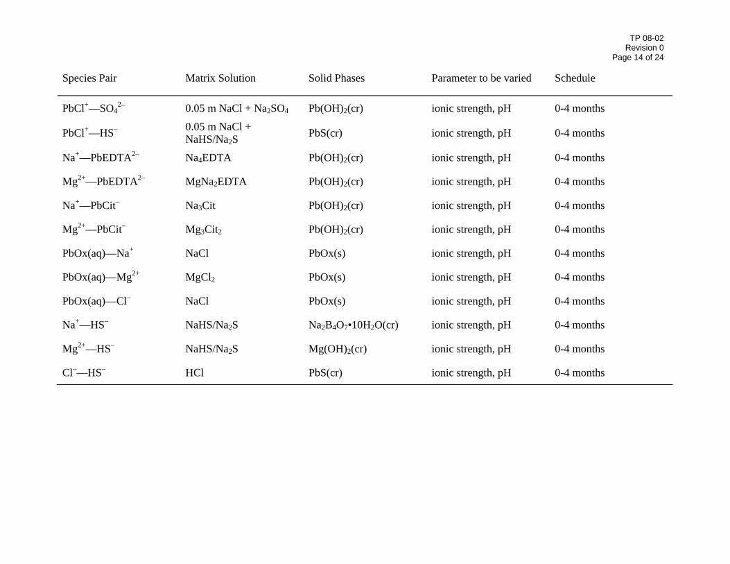
Table 3. Solutions, Controlling Phases and Schedule for Completion
Species Pair Matrix Solution Solid Phases Parameter to be varied Schedule
FeOH+—SO42– NaCl/Na2SO4 Fe(OH)2(cr) ionic strength, pH 0-4 months
FeOH+—CO32– NaHCO3/Na2CO3 FeCO3(cr) ionic strength, pH 0-4 months
FeOH+—HS– NaHS/Na2S FeS(mackinawite) ionic strength, pH 0-4 months
Fe2+—HS– NaHS FeS(mackinawite) ionic strength, pH 0-4 months
Na+—Fe(OH)3– NaCl Fe(OH)2(cr) ionic strength, pH 4-8 months
Mg2+—Fe(OH)3– MgCl2 Fe(OH)2(cr) ionic strength, pH 4-8 months
FeOx(aq)—Na+ NaCl FeOx•2H2O(s) ionic strength, pH 4-8 months
FeOx(aq)—Mg2+ MgCl2 FeOx•2H2O(s) ionic strength, pH 4-8 months
FeOx(aq)—Cl– NaCl FeOx•2H2O(s) ionic strength, pH 8-12 months
Na+—FeEDTA2– Na4EDTA Fe(OH)2(cr) ionic strength, pH 8-12 months
Mg2+—FeEDTA2– MgNa2EDTA Fe(OH)2(cr) ionic strength, pH 8-12 months
Na+—FeCit– Na3Cit Fe(OH)2(cr) ionic strength, pH 12-16 months
Mg2+—FeCit– Mg3Cit2 Fe(OH)2(cr) ionic strength, pH 12-16 months
PbCl+—HCO3– 0.05 m NaCl + NaHCO3 Pb(OH)2(cr) ionic strength, pH 0-4 months
PbCl+—CO32– 0.05 m NaCl + NaHCO3 Pb(OH)2(cr) ionic strength, pH 0-4 months
TP 08-02 Revision 0
Page 14 of 24
Species Pair Matrix Solution Solid Phases Parameter to be varied Schedule
PbCl+—SO42– 0.05 m NaCl + Na2SO4 Pb(OH)2(cr) ionic strength, pH 0-4 months
PbCl+—HS– 0.05 m NaCl + NaHS/Na2S PbS(cr) ionic strength, pH 0-4 months
Na+—PbEDTA2– Na4EDTA Pb(OH)2(cr) ionic strength, pH 0-4 months
Mg2+—PbEDTA2– MgNa2EDTA Pb(OH)2(cr) ionic strength, pH 0-4 months
Na+—PbCit– Na3Cit Pb(OH)2(cr) ionic strength, pH 0-4 months
Mg2+—PbCit– Mg3Cit2 Pb(OH)2(cr) ionic strength, pH 0-4 months
PbOx(aq)—Na+ NaCl PbOx(s) ionic strength, pH 0-4 months
PbOx(aq)—Mg2+ MgCl2 PbOx(s) ionic strength, pH 0-4 months
PbOx(aq)—Cl– NaCl PbOx(s) ionic strength, pH 0-4 months
Na+—HS– NaHS/Na2S Na2B4O7•10H2O(cr) ionic strength, pH 0-4 months
Mg2+—HS– NaHS/Na2S Mg(OH)2(cr) ionic strength, pH 0-4 months
Cl–—HS– HCl PbS(cr) ionic strength, pH 0-4 months
TP 08-02 Revision 0
Page 15 of 24
2.1.3 Task 3: Testing for Equilibrium
The time required for equilibration of a given sample will vary from several days to as long as several months. Therefore, regular monitoring of the samples will be required to deter-mine if equilibration is complete. When there is little change in the concentrations between adja-cent measurements (on the order of experimental uncertainty), characterization of the equilibrated state can begin. It is possible for metastable phases that are thermodynamically dif-ferent from the stable phases to precipitate out of these solutions. Consequently, the attainment of equilibrium will be demonstrated using two sets of experiments for each system: one that will approach equilibrium from the direction of supersaturation, and another from the direction of un-dersaturation.
2.1.4 Task 4: Characterization of Equilibrated Samples
Once the samples for a given system have come to equilibrium, it will be necessary to de-termine the concentrations of the various species within the solution. In addition, for systems in which iron species are being studied, samples will be analyzed to determine the concentrations of Fe(II) and Fe(III). In some cases where the expected solubilities are small, it may be possible to use other detection methods, such as GC/MS, to determine the solubilities indirectly.
In particular, samples containing Fe(II) phases will be preserved using hydrochloric acid,
glycolic acid, or another preservative under anoxic conditions before being removed from the glove box to prevent oxidation upon exposure to the atmosphere.
2.1.5 Task 5: Measurement of EDTA Solubilities
We will perform solubility experiments on EDTA phases such as Na4EDTA, Mg2EDTA, Ca2EDTA, and NaAlEDTA · nH2O in simple brines buffered by Mg(OH)2. We may also per-form confirmatory experiments using GWB and ERDA-6 brines. Other WIPP-relevant complex-ant systems, such as iron and lead phases and other complexants, may also be examined as necessary.
2.2 Experimental Procedures to be Used or Developed
2.2.1 General Procedures
Procedures for sample preparation and analysis, such as weighing and pipetting, are stan-dard laboratory analytical procedures. Instrumental analyses, such as those for use of the x-ray diffractometer and the ICP-AES, will be performed according to established procedures. Where necessary, new procedures will be implemented as outlined in NP 5-1, “Implementing Proce-dures.”
TP 08-02 Revision 0
Page 16 of 24
2.2.2 Solution Preparation
Simple brines used as the matrix for measuring the concentrations of dissolved species will be prepared according to SP 20-4, “Preparing Synthetic Brines for Geochemical Experi-ments.”
2.2.3 Redox Control
For samples containing Fe(II), redox control is necessary to prevent oxidation of Fe(II) to Fe(III). This will be accomplished by the use of an anoxic glove box that contains a noble metal catalyst and an atmosphere of 5 % H2 in Ar, which taken together convert oxygen to H2O down to < 1 ppm. There is a digital oxygen/hydrogen meter in the glove box which displays the current oxygen/hydrogen concentrations. This meter typically reads 000 for oxygen ppm when the glove box is undisturbed. We will maintain oxygen concentrations of 30 ppm or less during these ex-periments to limit the potential oxidation of Fe(II) to Fe(III).
Within the glove box, each solution will be contained within a sealed serum bottle, which
is prepared, capped and crimped inside the glove box. This second layer of protection prevents sample oxidation in the event of a leak in the glove box. The second layer also lowers the net oxygen tension inside the sample bottles compared to the glove box owing to the slow leak rate of serum-bottle septa. This dual-layer configuration has been tested with Fe(II) species and has shown its ability to maintain excellent redox control (Roselle 2007). Pb(II) is the stable oxidation state at normal atmospheric conditions; therefore, all experiments concerning Pb(II), except those involving interactions of Pb(II) with HS–, will be conducted without using an anoxic glove box.
2.2.4 Determination of Concentrations
The concentrations of dissolved species will be determined through the use of several dif-ferent experimental techniques. Ion chromatography will be used for determining anions, car-bonate concentration, and the oxidation state distribution of iron. Inductively coupled Plasma – Atomic Emission Spectroscopy (ICP-AES) will be used for determining cations (lead and iron), and total iron. We may use the IC for determining cations as well if there is an advantage in do-ing so. Colloidal material present can be studied using scanning electron microscopy, particle sizers and a zeta potential measurement instrument. The colloidal component of solubility will be separated from the solution using standard procedures such as filtration or centrifugation (Altmaier et al., 2004; Altmaier et al., 2005).
2.3 Coordination with Organizations Providing Inputs or Using the Results
No other organizations will provide inputs in the form of data, experimental sample analysis, data compilation, or interpretation of results. Therefore, no coordination of inputs is planned at this time.
TP 08-02 Revision 0
Page 17 of 24
The outcome of the experimental work described in this document will be used by SNL to determine Pitzer parameters for thermodynamic modeling within the PA program. The pa-rameters would be available for use by other DOE WIPP contractors as well performing solubil-ity tests in brine under WIPP-repository conditions. The results of this experimental work will be provided to the DOE CBFO for further evaluation.
2.4 Sources of Uncertainty
Sources of error and uncertainty in this TP include: • pH measurement • volume measurement • weighing errors • impure reagents • temperature • measurement uncertainty • uncertainty in characterization of solubility-controlling solid phases
Measurements of pH will follow SP 12-14 and SP 12-18. These SPs discuss the uncer-
tainty in and acceptance criteria for pH measurements. Errors in measuring volume or mass will have a considerable impact on the results, as the
concentrations of species are critical inputs, and large uncertainties in the volumes or masses will introduce large uncertainties in quantities derived from the concentration data. Therefore, uncer-tainties in volume measurements will be controlled by using Class A volumetric glassware. Mass measurements will be made using standard laboratory analytical balances following SP 12-1, or another similar SP if needed. SP 12-1 discusses uncertainty, calibration, and acceptance criteria in making mass measurements. Impurities in the reagents will be reduced by using chemicals that are certified as ACS reagent grade or better, unless certified ACS reagents are not available. If necessary, reagents will be purified using standard, documented procedures. The reagent grade and source will be documented in the appropriate scientific notebooks; if needed, purification procedures will also be described.
Although solubilities are not in general sensitive to small changes in temperature around
25°C, large-scale fluctuations of 10 degrees or more may have an adverse affect on the results. Consequently, the temperature will be monitored to ensure that it remains within the specified limits; observations will be fully documented in the appropriate scientific notebooks.

TP 08-02 Revision 0
Page 18 of 24
3 SAMPLE CONTROL
The sample control for the work under this Test Plan will follow NP 13-1. Each sample will be appropriately labeled. Sample preparation, utilization, and final disposition will be docu-mented. When samples are not in the possession of individuals designated as responsible for their custody, they shall be stored in a secure area with associated documentation (e.g. SNL WIPP Activity/Project Specific Procedure (SP) Form SP 13-1-1, “Chain of Custody”).

TP 08-02 Revision 0
Page 19 of 24
4 DATA QUALITY CONTROL
4.1 Measuring and Test Equipment (M&TE) A calibration program will be implemented for the work described in this TP in accor-
dance with NP 12-1, “Control of Measuring and Test Equipment.” This M&TE calibration pro-gram will meet the requirements in procedure NP 12-1. In addition, NP 13-1 and SNL Activity/Project Specific Procedure (SP) 13-1, “Chain of Custody,” identify requirements and appropriate forms for documenting and tracking sample possession. Computer-based data han-dling will follow NP 9-1, “Analyses.”
4.2 Data Acquisition Plan
Quality control of the Scientific Notebooks will be established by procedures described in NP 20-2, “Scientific Notebooks.” Methods for justification, evaluation, approval, and documen-tation of deviation from test standards and establishment of special prepared test procedures will be documented in the Scientific Notebooks. Procedures including use of replicates, spikes, split samples, control charts, blanks and reagent controls will be determined during the development of experimental techniques.
Numerical data obtained will be transferred from data printouts, electronic media, and
scientific notebooks to data files that will be compatible with analysis using qualified software (e.g., Microsoft Excel 2003 or NON_LIN). Data transfer and reduction shall be performed in such a way to ensure that data transfer is accurate, that no information is lost in the transfer, and that the input is completely recoverable. A copy of each resulting file will be included in the sci-entific notebook.
4.3 Data Qualification
All calculations performed as part of the activities of this test plan will be documented in scientific notebooks. The content and organization shall follow NP 20-2, “Scientific Notebooks.” The notebooks will be reviewed periodically for technical and QA content and adequacy, as ex-plained in procedure NP 20-2.
TP 08-02 Revision 0
Page 20 of 24
5 EQUIPMENT
5.1 Weighing Equipment
Several balances may be used for this project. Balance calibration checks will be per-formed daily or prior to use (whichever is less frequent) using NIST-traceable weight sets, which, in turn, are calibrated by the SNL Mechanical Calibration Laboratory every two years. The balance calibration will be performed according to SP 12-1, “Use of Laboratory Balances and Scales.” Balance calibration checks will be recorded in the current Balance Logbook, and a note indicating the page number of the calibration check and other pertinent information will be made within the appropriate Scientific Notebook.
5.2 Temperature Measuring Equipment
Mercury thermometers are used in the facility. A calibration check of these thermometers is performed annually against a digital thermometer, which is itself calibrated by the SNL Pri-mary Standards Laboratory every year. The results of these calibration checks are recorded on Form SP 12-20-1 per SP 12-20, “Thermometer Calibration Check.”
5.3 Volumetric Measuring Equipment Standard Laboratory Class A glassware (pipettes, volumetric flasks, etc.) will be used at
all times. In addition, several adjustable Eppendorf pipettes are available for use in the labora-tory. The calibration of Eppendorf pipettes will be checked routinely against a calibrated balance and documented in the scientific notebook. There is a 1% limit on the tolerance of the pipette calibration check.
5.4 Other Analytical Equipment • pH Meters/ion analyzer and autotitrators – An Orion EA 940 pH/ion analyzer (Mettler–
Toledo MA 235 pH/ion analyzer or other pH meter) will be used to measure pH. The range for all pH meters is 0.00 to 14.00. Electrodes will be calibrated according to SP 12-14, “Use of pH Meters and Electrodes” and SP 12-18, “Calibration of Mettler Toledo DL21 Titrator for Non-Standard pH Buffer Pairs.” Calibration checks of the pH will be recorded in the appropriate scientific notebook.
• Equipment for chemical analysis – Several instruments may be used for chemical analy-
ses. These include a Perkin Elmer Optima 3000 DV ICP/AES; a Bruker Analytical X-Ray Systems D8 Advance X-Ray Diffractometer; a Dionex IC3000 ion chromatograph; and a JEOL JSM-5900LV scanning electron microscope. These instruments will be cali-brated or a calibration check will be performed as applicable and documented in the ap-propriate instrument log book or scientific notebook.
TP 08-02 Revision 0
Page 21 of 24
6 TRAINING
All personnel involved in the experiments described in this TP will be trained and quali-fied for their assigned work. This requirement will be implemented through procedure NP 2-1, “Qualification and Training.” Evidence of training will be documented through Form NP 2-1-1, “Qualification and Training” and/or Form NP 2-1-2, “Training Record.”
Sample preparation procedures, which may vary from sample to sample as work scope
evolves, will be detailed in scientific notebooks, in accordance with procedure NP 20-2.
TP 08-02 Revision 0
Page 22 of 24
7 HEALTH AND SAFETY
All of the health and safety requirements relevant to the work described in this TP and the procedures that will be used to satisfy these requirements are described in ES&H standard oper-ating procedures. SP473548, “ES&H Standard Operating Procedure,” describes the nonra-diological hazards associated with these experiments and describes the procedures to deal with those hazards, including all the training requirements for personnel involved in conducting the experiments.

TP 08-02 Revision 0
Page 23 of 24
8 PERMITTING/LICENSING
There are no special licenses or permit requirements for the work described in this Test Plan.
TP 08-02 Revision 0
Page 24 of 24
9 REFERENCES
Altmaier, M., V. Metz, V. Neck, R. Muller and T. Fanghänel. 2003. "Solid-liquid equilibria of Mg(OH)2(cr) and Mg2(OH)3Cl 4H2O(cr) in the system Mg-Na-H-Cl-H2O at 25 C." Geo-chim. Cosmochim. Acta. Vol. 67, no. 19, 3595-3601.
Altmaier, M., V. Neck and T. Fanghänel. 2004. "Solubility and colloid formation of Th(IV) in
concentrated NaCl and MgCl2 solution." Radiochim. Acta. Vol. 92, 537-543. Altmaier, M., V. Neck, R. Muller and T. Fanghänel. 2005. "Solubility of ThO2.xH2O(am) in car-
bonate solution and the fomration of ternary Th(IV) hydroxide-carbonate complexes." Radiochim. Acta. Vol. 93, 83-92.
Harvie, C. E., N. Møller, and J. H. Weare. 1984. “The prediction of mineral solubilities in natural
waters. The Na-K-Mg-Ca-H-Cl-SO4-OH-HCO3-CO3-CO2-H2O system to high ionic strengths at 25°C.” Geochim. Cosmochim. Acta. Vol. 48, no. 4, 723-751.
Pitzer, K. S. 1973. “Thermodynamics of Electrolytes. I. Theoretical Basis and General Equa-tions.” J. Phys. Chem. Vol. 77, no. 2, 268.
Pitzer, K. S. 1975. “Thermodynamics of Electrolytes. V. Effects of Higher-Order Electrostatic Terms.” J. Solution Chem. Vol. 4, no. 3, 249.
Pitzer, K. S. 1991. Activity Coefficients in Electrolyte Solutions, 2nd ed. Boca Raton, FL: CRC Press.
Roselle, G. T. 2007. Scientific Notebook WIPP-FePb-1. Carlsbad, NM. Sandia National Labora-tories.
TP 08-02 Revision 0
Corporate Notice
NOTICE: This document was prepared as an account of work sponsored by an agency of the United States Government. Neither the United States Government nor any agency thereof, nor any of their employees, nor any of their contractors, subcontractors, or their employees, makes any warranty, express or implied, or assumes any legal liability or re-sponsibility for the accuracy, completeness, or usefulness or any information, apparatus, product or process disclosed, or represents that its use would not infringe privately owned rights. Reference herein to any specific commercial product, process or service by trade name, trademark, manufacturer, or otherwise, does not necessarily constitute or imply its endorsement, recommendation, or favoring by the United States Government, any agency thereof or any of their contractors or subcontractors. The views and opinions expressed herein do not necessarily state or reflect those of the United States Govern-ment, any agency thereof or any of their contractors. This document was authored by Sandia Corporation under Contract No. DE-AC04-94AL85000 with the United States Department of Energy’s National Nuclear Security Administration. Parties are allowed to download copies at no cost for internal use within your organization only provided that any copies made are true and accurate. Copies must include a statement acknowledging Sandia Corporation's authorship of the subject mat-ter.