Embed Size (px)
Citation preview
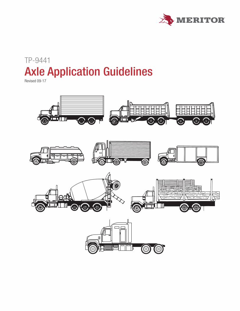
TP-9441
Axle Application GuidelinesRevised 09-17
Axle Application Guidelines
Copyright 2017 TP-9441Page ii Meritor, Inc. Revised 09-17
Table of Contents
Section I – Notes and Formulas ..............................................................................................................1Use of These Guidelines ............................................................................................................................1Conditions for Approval ..............................................................................................................................1Warranty .....................................................................................................................................................1Changes to Guidelines ...............................................................................................................................1Notes ..........................................................................................................................................................2Input Torque for Rear Drive Axle – Formulas ..............................................................................................4Manual Transmissions ................................................................................................................................4Traditional Analysis Method (Automatic Transmissions) .............................................................................4Maximum Turbine Torque Analysis Method (Allison Automatic Transmissions Only) .................................4Road Classifi cations for Operating Conditions ...........................................................................................5Generic Tire Information (Reference Only) .................................................................................................5RS/RT 145 Model Crossover to the MS/MT 14X Models ...........................................................................6
Section II — Structure Charts/On-Highway ............................................................................................7Front Non-Drive Steer and Rear Drive Axle Structural Guides ...................................................................7Job Site Maximum Axle Loading ................................................................................................................8Job Site Maximum Axle Loading Chart ......................................................................................................8Non-Drive Front Axle Creep Ratings ..........................................................................................................9Non-Drive Front Axle Structural Ratings .....................................................................................................913X Series Family ....................................................................................................................................1214X Series Family ....................................................................................................................................13FUELITE and FUELITE+ Tag Tandems (6x2 Confi gurations)* .................................................................15160 Series Family .....................................................................................................................................1517X EVO Series Family ............................................................................................................................16180/380 Series Family ..............................................................................................................................17Suspension and Axle Housing Requirements ..........................................................................................18Suspension and Axle Housing Requirements (Continued) ......................................................................19Suspension Type Glossary .......................................................................................................................19
Section III — Recommended Applications/Vocational Ratings .........................................................20Vehicle Types by Vocation .........................................................................................................................20Meritor Axle Models – Gross Axle Weight Ratings (GAWR) for all Vocations ...........................................21Meritor Axle Models – Gross Axle Weight Ratings (GAWR) for all Vocations ...........................................23Meritor Axle Models and Transfer Case Gross Axle Weight Ratings (GAWR) for all Vocations................24Linehaul ....................................................................................................................................................26City Delivery .............................................................................................................................................31Construction .............................................................................................................................................38Heavy Haul ...............................................................................................................................................43Logging .....................................................................................................................................................45Mining .......................................................................................................................................................48Oil Field ....................................................................................................................................................51Refuse ......................................................................................................................................................54
Axle Application Guidelines
TP-9441 Copyright 2017Revised 09-17 Meritor, Inc. Page iii
Section IV — Recommended Applications/Vocational Ratings .........................................................58School Bus ...............................................................................................................................................58Transit Bus ................................................................................................................................................61Intercity Coach ..........................................................................................................................................63Motorhome ...............................................................................................................................................65Fire ...........................................................................................................................................................68Rescue .....................................................................................................................................................72Yard Tractor ...............................................................................................................................................74
Section V — Product Information ..........................................................................................................76Tridem Axles .............................................................................................................................................76Tridem Guidelines Maximum GAWR by Axle Ratio ..................................................................................77Two-Speed Axle ........................................................................................................................................78Axle Ratings .............................................................................................................................................78Transfer Case ...........................................................................................................................................79All-Wheel Drive Application Guidelines ....................................................................................................79Single-Speed Transfer Case Torque Limits ...............................................................................................81Two-Speed Transfer Case Torque Limits ..................................................................................................81Heavy Duty Front Drive Steer ...................................................................................................................84
Section VI — Model Nomenclature and Glossary ................................................................................89New Front Non-Drive Axle Model Nomenclature ......................................................................................89Front Non-Drive Axle Nomenclature (Legacy) ..........................................................................................90New Model Nomenclature for 14X Model Series ......................................................................................91New Drive Axle Model Nomenclature Except for 14X Model Series (Includes Front Drive Steer Axle) ...92Drive Axle Model Nomenclature ...............................................................................................................93Transfer Case Model Nomenclature .........................................................................................................94Glossary ...................................................................................................................................................95
Axle Application GuidelinesSection I — Notes and Formulas
TP-9441 Copyright 2017Revised 09-17 Meritor, Inc. Page 1
Use of These Guidelines
Note: Section I applies to all vocations in this publication.
This document describes the approvable gross axle weight rating (GAWR), Axle Input Torque, Gross Engine Torque and gross vehicle weight (GVW) and/or gross combination weight (GCW) for Meritor Brand Axles used in the U.S., Canada and Mexico. This document is not intended to be used for any other purposes nor in any other territories.
Conditions for Approval
Axles can be approved for use in the vocations covered by this document when the axles meet all of the requirements for:
A. Structure
B. Maximum Torque
1. Axle Input Torque
2. Gross Engine Torque
C. GAWR, GVW, or GCW
D. Notes (starting on Page 2)
Note: Axle applications for other tire sizes, tracks, mounting centers, front axle KPI’s, Meritor axle models, engine/transmission torques beyond those listed, or GVW/GCW other than shown within this AXLE GUIDELINE may still be approvable.
For any questions concerning this document (interpretation and calculations) or for loadings, confi gurations or duty cycles outside the parameters of this guideline, contact the Meritor OnTrac™ Customer Call Center at 866-OnTrac1 (668-7221).
Warranty
Meritor branded axles included in the Guidelines that are operated within the vocational limitations set forth herein are covered by Meritor’s industry competitive warranty. For complete details (and specifi c coverage), refer to Meritor’s Warranty Guideline (Publication SP-95155).
Contact Meritor on questions concerning warranty coverage and application approvals for product used outside of these published Guidelines.
Increases in grades and/or number of stops/starts have a notable infl uence on the service life of the driving axles.
Changes to Guidelines
These Guidelines are subject to change at any time, without prior notice, at the discretion of Meritor. Please contact the Meritor OnTrac™ Customer Call Center at 866-OnTrac1 (668-7221) to confi rm you have the most recent Guideline available.
Axle Application GuidelinesSection I — Notes and Formulas
Copyright 2017 TP-9441Page 2 Meritor, Inc. Revised 09-17
Notes
1. Approval of the following optional features is also described in this document. All options may not be available on all axle models.
A. Driver-Controlled Differential Lock (DCDL)
B. Oil Pump
C. Advanced Lube
D. Aluminum Carriers
2. For review and approval of Brakes, Drivelines, Meritor WABCO Products, Suspensions, Telma Retarders for single axles only (not approved with tandems), Trailer Axles, Transfer Cases, Wheel Ends, and other components, contact the Meritor OnTrac™ Customer Call Center at 866-OnTrac1 (668-7221).
3. Attachment to the axle housing assembly and durability of the axle housing as a result of the suspension loadings is the responsibility of the original equipment manufacturer (OEM). Meritor will be responsible for bracket integrity and attachment only if:
A. The brackets are Meritor design;
B. Meritor welds the bracket to the housing; and
C. Meritor has established a prior agreement with the OEM.
4. When specifying a higher rated suspension than the accompanying axle or tandem, the maximum rating approved is that of the axle.
5. Where a chassis is being sold as an incomplete vehicle, it is the responsibility of the OEM and/or the dealer to accurately convey all approved axle loading information to the Body Builder. Also, it is the responsibility of the fi nal vehicle builder to ensure the assigned tagged values for GAWR and GVW/GCW do not exceed those limits approvable by this Guideline (this includes auxiliary axles and FMVSS brake standards).
6. Correct clamp load on the suspension bracket attached to the drive axle housing(s) must be maintained to prevent cracking and maintain housing integrity. See TMC RP643 maintenance guidelines to make sure fasteners are tight.
7. The OEM has the responsibility to determine steering axle specifi cs (maximum turn angle, tie rod arm ball position, steering arm ball location, geometry limits, etc.)
8. Vehicles operating outside of an approved Meritor application, such as a different vocation, drivetrain confi guration, load distribution changes, and testing of any kind, are not covered by the warranty. For complete details (and specifi c coverage), refer to Meritor’s Warranty Guideline (Publication SP-95155).
9. The use of NoSPIN® “differentials” in any single or tandem rear drive axle results in the exclusion of the axle shafts from coverage by the warranty. Certain other carrier components will also be excluded from warranty coverage if they no longer operate correctly as a result of a NoSPIN® failure or malfunction. Depending on axle loading, the NoSPIN® can cause all differential torque to be directed to one axle shaft causing overload (and potential failure). NoSPIN® is a registered trademark and product of Eaton Corporation.
10. Any use of Meritor components in vehicles equipped with an automatic transmission retarder must be submitted to Meritor for approval.
11. Any use of Meritor components in vehicle equipped with hybrid propulsion systems must be submitted to Meritor for approval.
12. Use of Meritor rear axles and drivelines in vehicles with All Wheel Drive confi guration must be submitted to Meritor for approval if high or low speed mismatch exceeds guidelines defi ned on page 82.
13. All front drive steer axles and transfer case applications must be submitted to Meritor for approval.
14. All Meritor drive axle models must not operate in conditions when axle oil temperature exceeds 250˚F (121˚C).
15. Focal mounted Telma retarders can be approved for single axles only.

Axle Application GuidelinesSection I — Notes and Formulas
TP-9441 Copyright 2017Revised 09-17 Meritor, Inc. Page 3
16. Tandems and tridems with a minimum GAWR rating of 46,000 can be approved with dual vehicle retardation devices (VRD) in the U.S., Canada and Mexico.
17. Information contained in this publication is effective as of the date of publication noted herein, and is subject to change without notice. Meritor reserves the right to revise the information presented.
18. Incorrect use of reverse gear or gears resulting in a coast load failure, which is considered a shock load failure, is not warranted.
19. Unless otherwise noted, the maximum allowable wheel outset is 0.56 inches for all axles. Use of the outset wheels will increase the track of the housing over the standard track with dual tires. Refer to the Axle Structural Charts section of these Guidelines for additional information on the GAWR based on the track width.
20. The move to lower numerical axle ratios increases the possibility of torque spikes occurring in the drivetrain. The OEM is responsible for ensuring that powertrain controls are in place to prevent transient torque spikes from exceeding the input torque limits stated in the vocational tables.
21. Use of retarders is not approved on vehicles equipped with MS-13X axles.
22. Job site ratings listed in this document pertain to Meritor axles only. The OEM should be aware that other components may have different job-site load ratings. It is the OEM’s responsibility to ensure all products are safely operated within the guidelines specifi ed by the respective product manufacturer.
23. All trailers are assumed to have brakes when reviewing tractors with trailers (semi or full) brake applications. If that is not the case, the OEM needs to note it on the application.
Axle Application GuidelinesSection I — Notes and Formulas
Copyright 2017 TP-9441Page 4 Meritor, Inc. Revised 09-17
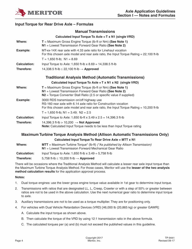
Input Torque for Rear Drive Axle – Formulas
Manual TransmissionsCalculated Input Torque To Axle = T x N1 (single VRD)
Where: T = Maximum Gross Engine Torque (lb-ft or Nm) (See Note 1)N1 = Lowest Transmission Forward Gear Ratio (See Note 2)
Example: MT-xx-14X rear axle with 4.33 axle ratio for Linehaul vocationFor this chosen axle model and rear axle ratio, the Input Torque Rating = 22,100 ft-lb
T = 1,650 ft-lb; N1 = 8.69
Calculation: Input Torque to Axle: 1,650 ft-lb x 8.69 = 14,338.5 ft-lb
Therefore: 14,338.5 ft-lb 22,100 ft-lb � Approved
Traditional Analysis Method (Automatic Transmissions)Calculated Input Torque To Axle = T x N1 x N2 (single VRD)
Where: T = Maximum Gross Engine Torque (lb-ft or Nm) (See Note 1)N1 = Lowest Transmission Forward Gear Ratio (See Note 2)N2 = Torque Converter Stall Ratio (2.5 or specifi c value if supplied)
Example: 3000 RDS transmission on/off highway useRS-160 rear axle with 6.14 axle ratio for Construction vocationFor this chosen axle model and rear axle ratio, the Input Torque Rating = 10,200 ft-lb
T = 1,650 ft-lb; N1 = 3.49; N2 = 2.5
Calculation: Input Torque to Axle: 1,650 lb-ft x 3.49 x 2.5 = 14,396.3 ft-lb
Therefore: 14,396.3 ft-lb > 10,200 � Not ApprovedNote: Calculated Input Torque needs to be less than Input Torque rating
Maximum Turbine Torque Analysis Method (Allison Automatic Transmissions Only)Calculated Input Torque To Rear Drive Axle = MTT x N1
Where: MTT = Maximum Turbine Torque* (lb-ft) (*As published by Allison Transmission)N1 = Lowest Transmission Forward Mechanical Gear Ratio
Calculation: Input Torque to Axle: 1,650 ft-lb x 3.49 = 5,758 ft-lb
Therefore: 5,758 ft-lb 10,200 ft-lb � Approved
There will be occasions where the Traditional Analysis Method will calculate a lesser rear axle input torque than the Maximum Turbine Torque Analysis Method. For those cases, Meritor will use the lesser of the two analysis method calculation results for the application approval process.
Notes:
1. Dual torque engines: use the lower gross engine torque value available in 1st gear to determine input torque.
2. Transmissions with ratios that are designated LL, L, Creep, Crawler or with a step of 50% or greater between ratios are not to be used in the above calculation. Use the next numerical gear ratio to determine input torque to axle.
3. Auxiliary transmissions are not to be used as a torque multiplier. They are for positioning only.
4. For vehicles with Dual Vehicle Retardation Devices (VRD) [46,000 lb (20,865 kg) or greater GAWR]:
A. Calculate the input torque as shown above.
B. Then calculate the torque of the VRD by using 12:1 transmission ratio in the above formula.
C. The calculated torques per (a) and (b) must not exceed the published values in this guideline.
Axle Application GuidelinesSection I — Notes and Formulas
TP-9441 Copyright 2017Revised 09-17 Meritor, Inc. Page 5
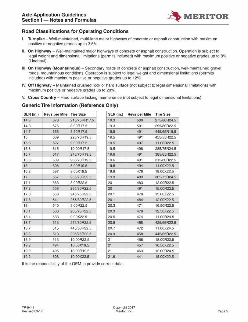
Road Classifi cations for Operating Conditions
I. Turnpike – Well-maintained, multi-lane major highways of concrete or asphalt construction with maximum positive or negative grades up to 3.5%.
II. On Highway – Well-maintained major highways of concrete or asphalt construction. Operation is subject to legal weight and dimensional limitations (permits included) with maximum positive or negative grades up to 8% (Linehaul).
III. On Highway (Mountainous) – Secondary roads of concrete or asphalt construction, well-maintained gravel roads, mountainous conditions. Operation is subject to legal weight and dimensional limitations (permits included) with maximum positive or negative grades up to 12%.
IV. Off Highway – Maintained crushed rock or hard surface (not subject to legal dimensional limitations) with maximum positive or negative grades up to 20%.
V. Cross Country – Hard surface lacking maintenance (not subject to legal dimensional limitations).
Generic Tire Information (Reference Only)
SLR (in.) Revs per Mile Tire Size SLR (in.) Revs per Mile Tire Size
14.3 673 215/75RR17.5 19.3 500 275/80R24.5
14.3 676 8.00R17.5 19.3 501 295/80R22.5
14.7 656 8.50R17.5 19.5 491 445/65R19.5
15 639 225/70R19.5 19.5 491 455/55R22.5
15.3 627 9.00R17.5 19.5 497 11.00R22.5
15.6 615 10.00R17.5 19.5 498 285/75R24.5
15.7 617 245/70R19.5 19.6 491 385/65R22.5
15.8 609 265/70R19.5 19.6 491 315/80R22.5
16 608 8.00R19.5 19.8 494 11.00X22.5
16.2 597 8.00X19.5 19.8 476 18.00X22.5
17 567 255/70R22.5 19.9 489 305/75R24.5
17.1 563 8.00R22.5 20 483 12.00R22.5
17.2 558 235/80R22.5 20 491 15.00R22.5
17.3 558 245/75R22.5 20.1 478 15.00X22.5
17.8 541 255/80R22.5 20.1 484 12.00X22.5
18 540 9.00R22.5 20.3 471 16.50R22.5
18.1 538 265/75R22.5 20.3 478 12.50X22.5
18.4 533 9.00X22.5 20.5 474 11.00R24.5
18.7 513 275/80R22.5 20.5 468 425/65R22.5
18.7 515 445/50R22.5 20.7 472 11.00X24.5
18.8 513 295/75R22.5 20.9 458 445/65R22.5
18.9 513 10.00R22.5 21 458 18.00R22.5
19.2 494 16.50X19.5 21 457 16.50X22.5
19.2 495 18.00R19.5 21 463 12.00R24.5
19.2 508 10.00X22.5 21.6 441 18.00X22.5
It is the responsibility of the OEM to provide correct data.
Axle Application GuidelinesSection I — Notes and Formulas
Copyright 2017 TP-9441Page 6 Meritor, Inc. Revised 09-17
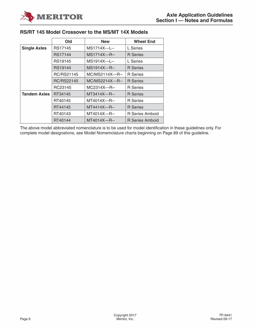
RS/RT 145 Model Crossover to the MS/MT 14X Models
Old New Wheel End
Single Axles RS17145 MS1714X---L-- L Series
RS17144 MS1714X---R-- R Series
RS19145 MS1914X---L-- L Series
RS19144 MS1914X---R-- R Series
RC/RS21145 MC/MS2114X---R-- R Series
RC/RS22145 MC/MS2214X---R-- R Series
RC23145 MC2314X---R-- R Series
Tandem Axles RT34145 MT3414X---R-- R Series
RT40145 MT4014X---R-- R Series
RT44145 MT4414X---R-- R Series
RT40143 MT4014X---R-- R Series Amboid
RT40144 MT4014X---R-- R Series Amboid
The above model abbreviated nomenclature is to be used for model identifi cation in these guidelines only. For complete model designations, see Model Nomemclature charts beginning on Page 89 of this guideline.

Axle Application GuidelinesSection II — Structure Charts/On-Highway
TP-9441 Copyright 2017Revised 09-17 Meritor, Inc. Page 7
SECTION II — STRUCTURE CHARTS/ON-HIGHWAY
Front Non-Drive Steer and Rear Drive Axle Structural Guides
Beam Drop“A” = Kingpin pivot to spring pad
The following items are used to determine the structural loading on the axle:
1. The maximum value of the Static Load Radius (SLR) of the tires
2. Suspension Mounting Centers (SMC)
3. The standard front axle King Pin Intersection (KPI) dimensions (Front Axles Only)
4. Axle Housing Wall Thickness (HWT) (Fabricated Axles Only)
5. Tire Track
DUAL TIRES
Axle Application GuidelinesSection II — Structure Charts/On-Highway
Copyright 2017 TP-9441Page 8 Meritor, Inc. Revised 09-17
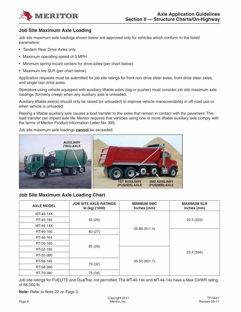
Job Site Maximum Axle Loading
Job site maximum axle loadings shown below are approved only for vehicles which conform to the listed parameters:
• Tandem Rear Drive Axles only
• Maximum operating speed of 5 MPH
• Minimum spring mount centers for drive axles (per chart below)
• Maximum tire SLR (per chart below).
Application requests must be submitted for job site ratings for front non-drive steer axles, front drive steer axles, and single rear drive axles.
Operators using vehicle equipped with auxiliary liftable axles (tag or pusher) must consider job site maximum axle loadings (formerly creep) when any auxiliary axle is unloaded.
Auxiliary liftable axle(s) should only be raised (or unloaded) to improve vehicle maneuverability in off-road use or when vehicle is unloaded.
Raising a liftable auxiliary axle causes a load transfer to the axles that remain in contact with the pavement. This load transfer can impact axle life. Meritor requires that vehicles using one or more liftable auxiliary axle comply with the terms of Meritor Product Information Letter No. 395.
Job site maximum axle loadings cannot be exceeded.
Job Site Maximum Axle Loading Chart
AXLE MODELJOB SITE AXLE RATINGS
lb (kg) (1000)MINIMUM SMC
Inches (mm)MAXIMUM SLR
Inches (mm)
MT-40-14X
55 (25)
35.88 (911.4)
20.5 (503)RT-40-160
MT-44-14X
RT-46-160 60 (27)
23.4 (594)
RT-46-164
65 (29)RT-50-160
RT-52-185
35.50 (901.7)
RT-52-380
RT-58-18570 (32)
RT-58-380
RT-70-380 75 (34)
Job site ratings for FUELITE and DualTrac not permitted. The MT-40-14x and MT-44-14x have a Max GVWR rating of 68,000 lb.
Note: Refer to Note 22 on Page 3.
AUXILIARY (TAG) AXLE
1ST AUXILIARY (PUSHER) AXLE
2ND AUXILIARY (PUSHER) AXLE
Axle Application GuidelinesSection II — Structure Charts/On-Highway
TP-9441 Copyright 2017Revised 09-17 Meritor, Inc. Page 9
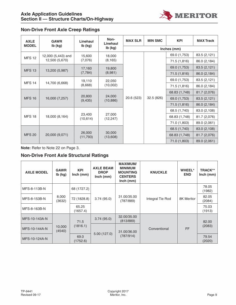
Non-Drive Front Axle Creep Ratings
AXLE MODEL
GAWRlb (kg)
Linehaullb (kg)
Non-Linehaul lb (kg)
MAX SLR MIN SMC KPI MAX Track
Inches (mm)
MFS 1212,000 (5,443) and
12,500 (5,670)15,600 (7,076)
18,000 (8,165)
20.6 (523) 32.5 (826)
69.0 (1,753) 83.5 (2,121)
71.5 (1,816) 86.0 (2,184)
MFS 13 13,200 (5,987)17,160 (7,784)
19,800 (8,981)
69.0 (1,753) 83.5 (2,121)
71.5 (1,816) 86.0 (2,184)
MFS 14 14,700 (6,668)19,110 (8,668)
22,050 (10,002)
69.0 (1,753) 83.5 (2,121)
71.5 (1,816) 86.0 (2,184)
MFS 16 16,000 (7,257)20,800 (9,435)
24,000 (10,886)
68.83 (1,748) 81.7 (2,076)
69.0 (1,753) 83.5 (2,121)
71.5 (1,816) 86.0 (2,184)
MFS 18 18,000 (8,164)23,400
(10,614)27,000
(12,247)
68.5 (1,740) 83.0 (2,108)
68.83 (1,748) 81.7 (2,076)
71.0 (1,803) 89.0 (2,061)
MFS 20 20,000 (9,071)26,000
(11,793)30,000
(13,608)
68.5 (1,740) 83.0 (2,108)
68.83 (1,748) 81.7 (2,076)
71.0 (1,803) 89.0 (2,061)
Note: Refer to Note 22 on Page 3.
Non-Drive Front Axle Structural Ratings
AXLE MODELGAWRlb (kg)
KPIInch (mm)
AXLE BEAM DROP
Inch (mm)
MAXIMUM/ MINIMUM
MOUNTING CENTERSInch (mm)
KNUCKLEWHEEL*
ENDTRACK**Inch (mm)
MFS-8-113B-N
8,000 (3632)
68 (1727.2)
3.74 (95.0)31.00/35.00(787/889)
Integral Tie Rod 8K Meritor
78.05(1982)
MFS-8-153B-N 72 (1828.8)82.05(2084)
MFS-8-163B-N65.25
(1657.4)75.03(1913)
MFS-10-143A-N
10,000 (4540)
71.5 (1816.1)
3.74 (95.0)32.00/35.00 (813/889)
Conventional FF
82.00 (2083)
MFS-10-144A-N5.00 (127.0)
31.00/36.00 (787/914)
MFS-10-124A-N69.0
(1752.6)79.54 (2020)

Axle Application GuidelinesSection II — Structure Charts/On-Highway
Copyright 2017 TP-9441Page 10 Meritor, Inc. Revised 09-17
AXLE MODELGAWRlb (kg)
KPIInch (mm)
AXLE BEAM DROP
Inch (mm)
MAXIMUM/ MINIMUM
MOUNTING CENTERSInch (mm)
KNUCKLEWHEEL*
ENDTRACK**Inch (mm)
MFS-12-143A-N
12,000 (5448)
71.5 (1816.1)
3.74 (95.0)32.50/35.00 (826/889)
Conventional
FF
82.00 (2083)
MFS-12-144A-N5.00 (127.0)
31.00/36.00 (787/914)
MFS-12-124A-N
69.0 (1752.6)
79.54(2020)
MFS-12-122A-N 3.50 (88.9)32.50/35.00 (826/889)
MFS-12-123A-N3.5/2.0
(88.9/51.0)
MFS-12-122B-N69.0
(1752.6)
3.50 (88.9)32.0/35.0 (812/889)
Integral Tie Rod79.54(2020)
MFS-12-122C-NIntegral Tie Rod and
Torque Plate
MFS-12-132B-N71.0
(1803.4)
Integral Tie Rod82.00 (2083)
MFS-12-132C-NIntegral Tie Rod and
Torque Plate
MFS-12E-122-N
12,500 (5806)
69.0 (1752.6)
3.50 (88.9)32.50/35.00 (826/889)
Conventional
FF
79.54 (2020)
MFS-12E-143A-N71.5
(1816.1)3.74 (95.0)
82.00 (2083)
MFS-12E-122B-N69.0
(1752.6)
3.50 (88.9)32.0/35.0 (812/889)
Integral Tie Rod79.54 (2020)
MFS-12E-122C-NIntegral Tie Rod and
Torque Plate
MFS-12E-132B-N71.5
(1816.1)
Integral Tie Rod82.00 (2083)
MFS-12E-132C-NIntegral Tie Rod and
Torque Plate
MFS-13-122B-N
13,000 (5902)
69.0 (1752.6)
3.50 (88.9)32.0/35.0 (812/889)
Integral Tie Rod
FF
79.54 (2020)
MFS-13-122C-NIntegral Tie Rod and
Torque Plate
MFS-13-132B-N71.0
(1803.4)
Integral Tie Rod82.00 (2083)
MFS-13-132C-NIntegral Tie Rod and
Torque Plate
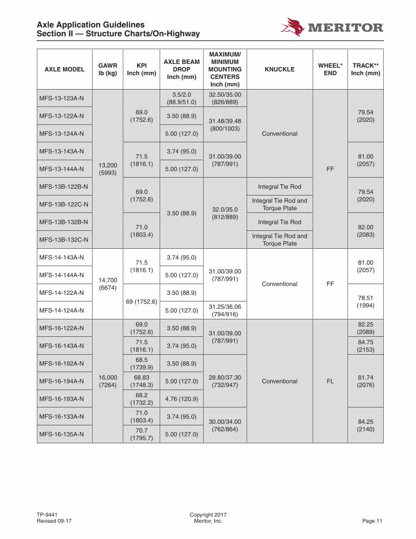
Axle Application GuidelinesSection II — Structure Charts/On-Highway
TP-9441 Copyright 2017Revised 09-17 Meritor, Inc. Page 11
AXLE MODELGAWRlb (kg)
KPIInch (mm)
AXLE BEAM DROP
Inch (mm)
MAXIMUM/ MINIMUM
MOUNTING CENTERSInch (mm)
KNUCKLEWHEEL*
ENDTRACK**Inch (mm)
MFS-13-123A-N
13,200 (5993)
69.0 (1752.6)
3.5/2.0(88.9/51.0)
32.50/35.00 (826/889)
Conventional
FF
79.54 (2020)
MFS-13-122A-N 3.50 (88.9)31.48/39.48(800/1003)
MFS-13-124A-N 5.00 (127.0)
MFS-13-143A-N71.5
(1816.1)
3.74 (95.0)31.00/39.00(787/991)
81.00 (2057)
MFS-13-144A-N 5.00 (127.0)
MFS-13B-122B-N69.0
(1752.6)
3.50 (88.9)32.0/35.0 (812/889)
Integral Tie Rod79.54 (2020)
MFS-13B-122C-NIntegral Tie Rod and
Torque Plate
MFS-13B-132B-N71.0
(1803.4)
Integral Tie Rod82.00 (2083)
MFS-13B-132C-NIntegral Tie Rod and
Torque Plate
MFS-14-143A-N
14,700(6674)
71.5 (1816.1)
3.74 (95.0)
31.00/39.00(787/991)
Conventional FF
81.00 (2057)
MFS-14-144A-N 5.00 (127.0)
MFS-14-122A-N69 (1752.6)
3.50 (88.9)78.51(1994)
MFS-14-124A-N 5.00 (127.0)31.25/36.06 (794/916)
MFS-16-122A-N
16,000 (7264)
69.0 (1752.6)
3.50 (88.9)31.00/39.00 (787/991)
Conventional FL
82.25(2089)
MFS-16-143A-N71.5
(1816.1)3.74 (95.0)
84.75(2153)
MFS-16-192A-N68.5
(1739.9)3.50 (88.9)
28.80/37.30 (732/947)
81.74(2076)
MFS-16-194A-N68.83
(1748.3)5.00 (127.0)
MFS-16-193A-N68.2
(1732.2)4.76 (120.9)
MFS-16-133A-N71.0
(1803.4)3.74 (95.0)
30.00/34.00 (762/864)
84.25 (2140)
MFS-16-135A-N70.7
(1795.7)5.00 (127.0)
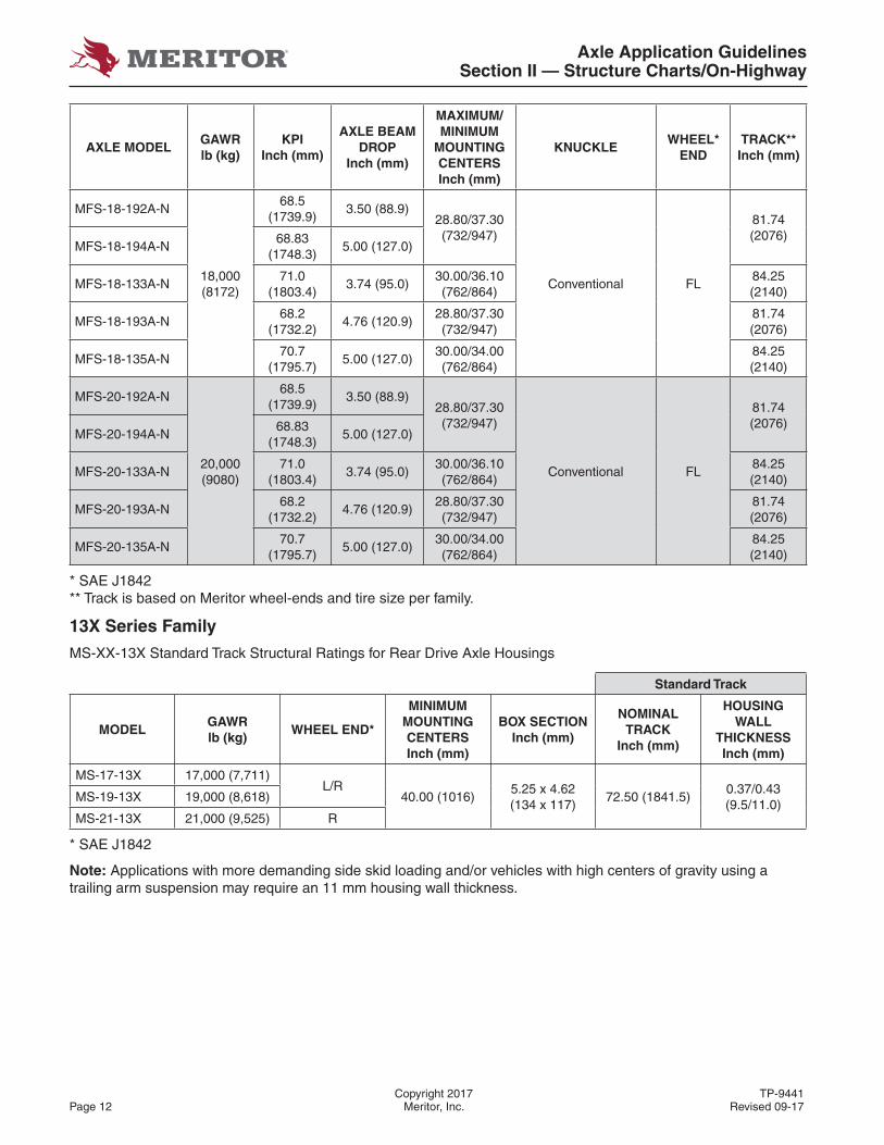
Axle Application GuidelinesSection II — Structure Charts/On-Highway
Copyright 2017 TP-9441Page 12 Meritor, Inc. Revised 09-17
AXLE MODELGAWRlb (kg)
KPIInch (mm)
AXLE BEAM DROP
Inch (mm)
MAXIMUM/ MINIMUM
MOUNTING CENTERSInch (mm)
KNUCKLEWHEEL*
ENDTRACK**Inch (mm)
MFS-18-192A-N
18,000(8172)
68.5 (1739.9)
3.50 (88.9)28.80/37.30(732/947)
Conventional FL
81.74 (2076)
MFS-18-194A-N68.83
(1748.3)5.00 (127.0)
MFS-18-133A-N71.0
(1803.4)3.74 (95.0)
30.00/36.10(762/864)
84.25 (2140)
MFS-18-193A-N68.2
(1732.2)4.76 (120.9)
28.80/37.30 (732/947)
81.74 (2076)
MFS-18-135A-N70.7
(1795.7)5.00 (127.0)
30.00/34.00 (762/864)
84.25 (2140)
MFS-20-192A-N
20,000 (9080)
68.5 (1739.9)
3.50 (88.9)28.80/37.30(732/947)
Conventional FL
81.74 (2076)
MFS-20-194A-N68.83
(1748.3)5.00 (127.0)
MFS-20-133A-N71.0
(1803.4)3.74 (95.0)
30.00/36.10(762/864)
84.25 (2140)
MFS-20-193A-N68.2
(1732.2)4.76 (120.9)
28.80/37.30 (732/947)
81.74 (2076)
MFS-20-135A-N70.7
(1795.7)5.00 (127.0)
30.00/34.00 (762/864)
84.25 (2140)
* SAE J1842** Track is based on Meritor wheel-ends and tire size per family.
13X Series Family
MS-XX-13X Standard Track Structural Ratings for Rear Drive Axle Housings
Standard Track
MODELGAWRlb (kg)
WHEEL END*
MINIMUMMOUNTING CENTERSInch (mm)
BOX SECTIONInch (mm)
NOMINAL TRACK
Inch (mm)
HOUSING WALL
THICKNESSInch (mm)
MS-17-13X 17,000 (7,711)L/R
40.00 (1016)5.25 x 4.62 (134 x 117)
72.50 (1841.5)0.37/0.43 (9.5/11.0)
MS-19-13X 19,000 (8,618)
MS-21-13X 21,000 (9,525) R
* SAE J1842
Note: Applications with more demanding side skid loading and/or vehicles with high centers of gravity using a trailing arm suspension may require an 11 mm housing wall thickness.
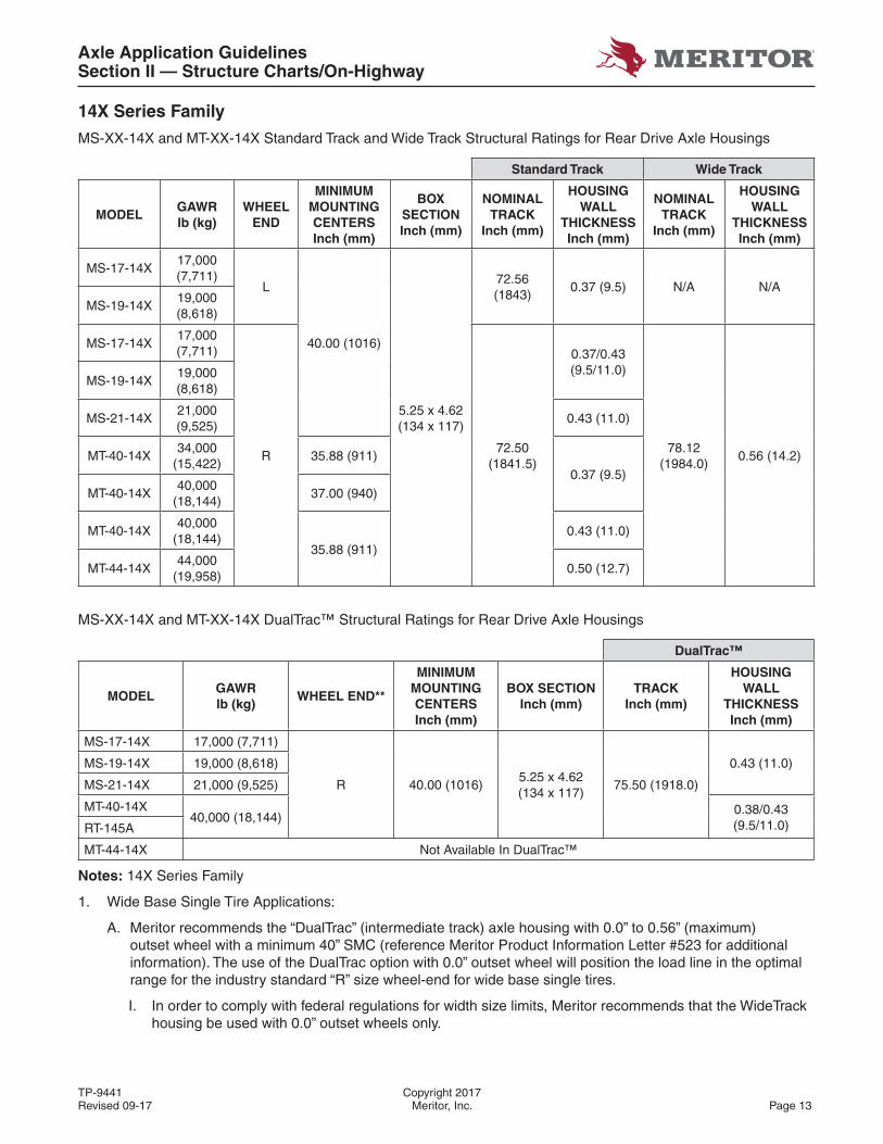
Axle Application GuidelinesSection II — Structure Charts/On-Highway
TP-9441 Copyright 2017Revised 09-17 Meritor, Inc. Page 13
14X Series Family
MS-XX-14X and MT-XX-14X Standard Track and Wide Track Structural Ratings for Rear Drive Axle Housings
Standard Track Wide Track
MODELGAWRlb (kg)
WHEELEND
MINIMUMMOUNTING CENTERSInch (mm)
BOX SECTIONInch (mm)
NOMINAL TRACK
Inch (mm)
HOUSING WALL
THICKNESSInch (mm)
NOMINAL TRACK
Inch (mm)
HOUSING WALL
THICKNESSInch (mm)
MS-17-14X17,000(7,711)
L
40.00 (1016)
5.25 x 4.62 (134 x 117)
72.56 (1843)
0.37 (9.5) N/A N/AMS-19-14X
19,000(8,618)
MS-17-14X17,000(7,711)
R72.50
(1841.5)
0.37/0.43 (9.5/11.0)
78.12 (1984.0)
0.56 (14.2)
MS-19-14X19,000(8,618)
MS-21-14X21,000(9,525)
0.43 (11.0)
MT-40-14X34,000
(15,422)35.88 (911)
0.37 (9.5)MT-40-14X
40,000(18,144)
37.00 (940)
MT-40-14X40,000
(18,144)35.88 (911)
0.43 (11.0)
MT-44-14X44,000
(19,958)0.50 (12.7)
MS-XX-14X and MT-XX-14X DualTrac™ Structural Ratings for Rear Drive Axle Housings
DualTrac™
MODELGAWRlb (kg)
WHEEL END**
MINIMUMMOUNTING CENTERSInch (mm)
BOX SECTIONInch (mm)
TRACKInch (mm)
HOUSING WALL
THICKNESSInch (mm)
MS-17-14X 17,000 (7,711)
R 40.00 (1016)5.25 x 4.62 (134 x 117)
75.50 (1918.0)
0.43 (11.0)MS-19-14X 19,000 (8,618)
MS-21-14X 21,000 (9,525)
MT-40-14X40,000 (18,144)
0.38/0.43 (9.5/11.0)RT-145A
MT-44-14X Not Available In DualTrac™
Notes: 14X Series Family
1. Wide Base Single Tire Applications:
A. Meritor recommends the “DualTrac” (intermediate track) axle housing with 0.0” to 0.56” (maximum) outset wheel with a minimum 40” SMC (reference Meritor Product Information Letter #523 for additional information). The use of the DualTrac option with 0.0” outset wheel will position the load line in the optimal range for the industry standard “R” size wheel-end for wide base single tires.
I. In order to comply with federal regulations for width size limits, Meritor recommends that the WideTrack housing be used with 0.0” outset wheels only.

Axle Application GuidelinesSection II — Structure Charts/On-Highway
Copyright 2017 TP-9441Page 14 Meritor, Inc. Revised 09-17
II. Wheel outset up to 2” (maximum) is only approved for standard track 11 mm axle housing wall thickness and 40” minimum suspension mounting centers for use in Linehaul and City Delivery applications with the following GAWR:
Standard Track Axle Housing – 11 mm Wall Thickness
Maximum Track (inch)Tandem Maximum
GAWR (lb)
Up to 73.3 40,000
73.4-75.1 40,000
75.2-76.0 39,000
B. Important considerations for Meritor Axle Housing:
I. Unless otherwise specifi ed by Meritor, it is customer/vehicle OEM responsibility to defi ne wheel-end specifi cations and to qualify the ratings for the wheel-end system including hubs, wheels and tires and to defi ne the proper wheel-end maintenance practices to avoid premature wheel-end issues.
• The use of 2" outset wheels shifts the load line outboard, unbalancing the load distribution toward the outer bearing. It is therefore recommended that more recent pre-adjusted wheel-end systems with increased capability be used, rather than conventional or adjustable wheel-end systems.
II. Follow OEM recommendations regarding inspection intervals and component replacement. Meritor recommends inspection of wheel-end system and replacement of components on at least an annual basis, with more frequent inspection and replacement as may be warranted by specifi c application. Reference TMC RP-644A (Wheel-End Conditions Analysis Guide), and appropriate manufacturer’s service recommendations for details.
III. Meritor recommends performing axle housing spindle inspection concurrently with the wheel-end inspection of the hub bearings, hub seals and lubricant. Evidence of axle housing spindle wear at bearing seats requires axle housing replacement. Do not repair the axle housing spindle.
• Do not install single wide base tires with 2” outset wheels on existing vehicles. Meritor does not approve such retrofi ts. Consult the vehicle OEM for guidance
IV. Failure to follow these recommendations will void the Meritor warranty coverage.
3. Applications with more demanding side skid loading and/or vehicles with high centers of gravity using a trailing arm suspension may require an 11 mm housing wall thickness.
4. L series wheel end and 9.5 mm housings are not approved for Mexico.
5. DualTrac™ approved for Linehaul and City Delivery, other vocations may be approvable (contact Meritor).
Axle Application GuidelinesSection II — Structure Charts/On-Highway
TP-9441 Copyright 2017Revised 09-17 Meritor, Inc. Page 15
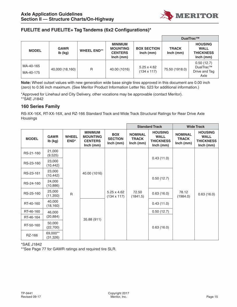
FUELITE and FUELITE+ Tag Tandems (6x2 Confi gurations)*
DualTrac™
MODELGAWRlb (kg)
WHEEL END**
MINIMUMMOUNTING CENTERSInch (mm)
BOX SECTIONInch (mm)
TRACKInch (mm)
HOUSING WALL
THICKNESSInch (mm)
MA-40-165
MA-40-17540,000 (18,160) R 40.00 (1016)
5.25 x 4.62 (134 x 117)
75.50 (1918.0)
0.50 (12.7)DualTrac™
Drive and Tag Axle
Note: Wheel outset values with new generation wide base single tires approved in this document are 0.00 inch (zero) to 0.56 inch maximum. (See Meritor Product Information Letter No. 523 for additional information.)
*Approved for Linehaul and City Delivery, other vocations may be approvable (contact Meritor). **SAE J1842
160 Series Family
RS-XX-16X, RT-XX-16X, and RZ-166 Standard Track and Wide Track Structural Ratings for Rear Drive Axle Housings
Standard Track Wide Track
MODELGAWRlb (kg)
WHEELEND*
MINIMUMMOUNTING CENTERSInch (mm)
BOX SECTIONInch (mm)
NOMINAL TRACK
Inch (mm)
HOUSING WALL
THICKNESSInch (mm)
NOMINALTRACK
Inch (mm)
HOUSING WALL
THICKNESSInch (mm)
RS-21-16021,000(9,525)
R
40.00 (1016)
5.25 x 4.62 (134 x 117)
72.50 (1841.5)
0.43 (11.0)
78.12 (1984.0)
0.63 (16.0)
RS-23-16023,000
(10,442)
RS-23-16123,000
(10,442)0.50 (12.7)
RS-24-16024,000
(10,886)
RS-25-16025,000
(11,350)0.63 (16.0)
RT-40-16040,000
(18,160)
35.88 (911)
0.43 (11.0)
RT-46-160 46,000(20,884)
0.50 (12.7)
RT-46-164
0.63 (16.0)RT-50-160
50,000(22,700)
RZ-16669,000**(31,326)
*SAE J1842**See Page 77 for GAWR ratings and required tire SLR.
Axle Application GuidelinesSection II — Structure Charts/On-Highway
Copyright 2017 TP-9441Page 16 Meritor, Inc. Revised 09-17
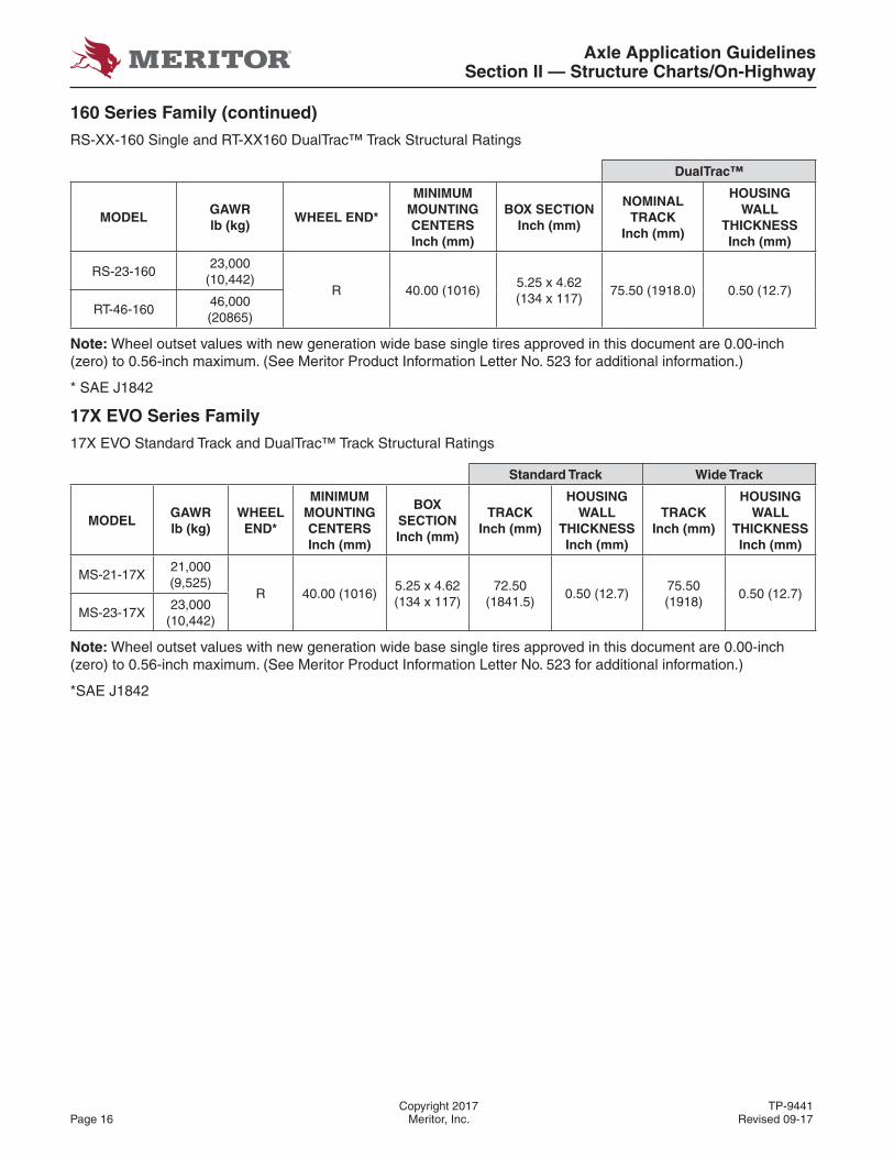
160 Series Family (continued)
RS-XX-160 Single and RT-XX160 DualTrac™ Track Structural Ratings
DualTrac™
MODELGAWRlb (kg)
WHEEL END*
MINIMUMMOUNTING CENTERSInch (mm)
BOX SECTIONInch (mm)
NOMINALTRACK
Inch (mm)
HOUSING WALL
THICKNESSInch (mm)
RS-23-16023,000
(10,442)R 40.00 (1016)
5.25 x 4.62 (134 x 117)
75.50 (1918.0) 0.50 (12.7)RT-46-160
46,000 (20865)
Note: Wheel outset values with new generation wide base single tires approved in this document are 0.00-inch (zero) to 0.56-inch maximum. (See Meritor Product Information Letter No. 523 for additional information.)
* SAE J1842
17X EVO Series Family
17X EVO Standard Track and DualTrac™ Track Structural Ratings
Standard Track Wide Track
MODELGAWRlb (kg)
WHEELEND*
MINIMUMMOUNTING CENTERSInch (mm)
BOX SECTIONInch (mm)
TRACKInch (mm)
HOUSING WALL
THICKNESSInch (mm)
TRACKInch (mm)
HOUSING WALL
THICKNESSInch (mm)
MS-21-17X21,000(9,525)
R 40.00 (1016)5.25 x 4.62 (134 x 117)
72.50 (1841.5)
0.50 (12.7)75.50 (1918)
0.50 (12.7)MS-23-17X
23,000(10,442)
Note: Wheel outset values with new generation wide base single tires approved in this document are 0.00-inch (zero) to 0.56-inch maximum. (See Meritor Product Information Letter No. 523 for additional information.)
*SAE J1842
Axle Application GuidelinesSection II — Structure Charts/On-Highway
TP-9441 Copyright 2017Revised 09-17 Meritor, Inc. Page 17
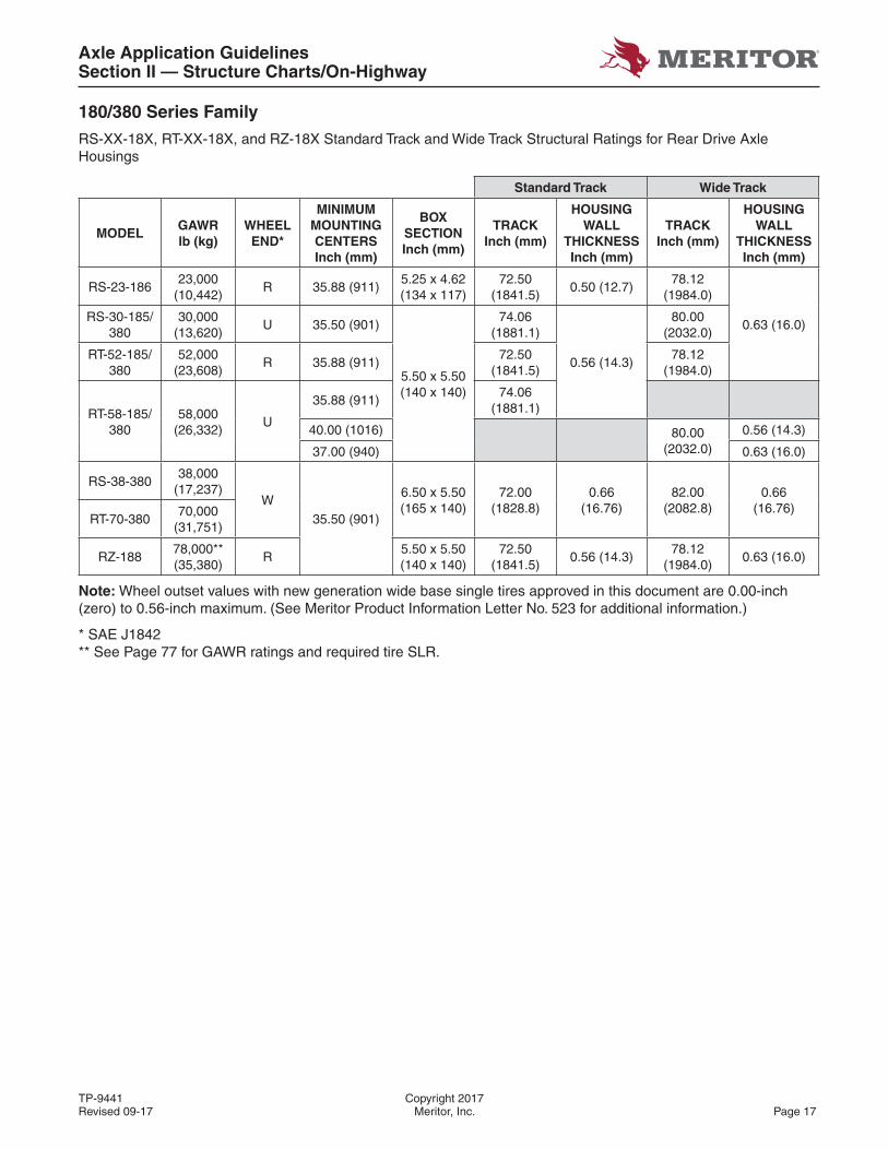
180/380 Series Family
RS-XX-18X, RT-XX-18X, and RZ-18X Standard Track and Wide Track Structural Ratings for Rear Drive Axle Housings
Standard Track Wide Track
MODELGAWRlb (kg)
WHEELEND*
MINIMUMMOUNTING CENTERSInch (mm)
BOX SECTIONInch (mm)
TRACKInch (mm)
HOUSING WALL
THICKNESSInch (mm)
TRACKInch (mm)
HOUSING WALL
THICKNESSInch (mm)
RS-23-18623,000
(10,442)R 35.88 (911)
5.25 x 4.62 (134 x 117)
72.50(1841.5)
0.50 (12.7)78.12
(1984.0)
0.63 (16.0)RS-30-185/
38030,000
(13,620)U 35.50 (901)
5.50 x 5.50 (140 x 140)
74.06(1881.1)
0.56 (14.3)
80.00(2032.0)
RT-52-185/380
52,000(23,608)
R 35.88 (911)72.50
(1841.5)78.12
(1984.0)
RT-58-185/380
58,000(26,332)
U
35.88 (911)74.06
(1881.1)
40.00 (1016) 80.00(2032.0)
0.56 (14.3)
37.00 (940) 0.63 (16.0)
RS-38-38038,000
(17,237)W
35.50 (901)
6.50 x 5.50 (165 x 140)
72.00 (1828.8)
0.66 (16.76)
82.00 (2082.8)
0.66 (16.76)
RT-70-38070,000
(31,751)
RZ-18878,000**(35,380)
R5.50 x 5.50 (140 x 140)
72.50 (1841.5)
0.56 (14.3)78.12
(1984.0)0.63 (16.0)
Note: Wheel outset values with new generation wide base single tires approved in this document are 0.00-inch (zero) to 0.56-inch maximum. (See Meritor Product Information Letter No. 523 for additional information.)
* SAE J1842** See Page 77 for GAWR ratings and required tire SLR.
Axle Application GuidelinesSection II — Structure Charts/On-Highway
Copyright 2017 TP-9441Page 18 Meritor, Inc. Revised 09-17
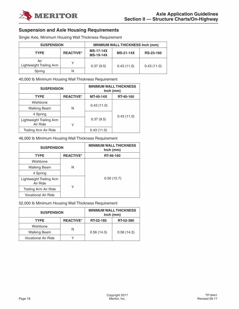
Suspension and Axle Housing Requirements
Single Axle, Minimum Housing Wall Thickness Requirement
SUSPENSION MINIMUM WALL THICKNESS Inch (mm)
TYPE REACTIVE*MS-17-14XMS-19-14X
MS-21-14X RS-23-160
AirLightweight Trailing Arm
Y0.37 (9.5) 0.43 (11.0) 0.43 (11.0)
Spring N
40,000 lb Minimum Housing Wall Thickness Requirement
SUSPENSIONMINIMUM WALL THICKNESS
Inch (mm)
TYPE REACTIVE* MT-40-14X RT-40-160
Wishbone
N 0.43 (11.0)
0.43 (11.0)
Walking Beam
4 Spring0.37 (9.5)Lightweight Trailing Arm
Air Ride YTrailing Arm Air Ride 0.43 (11.0)
46,000 lb Minimum Housing Wall Thickness Requirement
SUSPENSIONMINIMUM WALL THICKNESS
Inch (mm)
TYPE REACTIVE* RT-46-160
Wishbone
N
0.50 (12.7)
Walking Beam
4 Spring
Lightweight Trailing Arm Air Ride
YTrailing Arm Air Ride
Vocational Air Ride
52,000 lb Minimum Housing Wall Thickness Requirement
SUSPENSIONMINIMUM WALL THICKNESS
Inch (mm)
TYPE REACTIVE* RT-52-185 RT-52-380
WishboneN
0.56 (14.3) 0.56 (14.3)Walking Beam
Vocational Air Ride Y
Axle Application GuidelinesSection II — Structure Charts/On-Highway
TP-9441 Copyright 2017Revised 09-17 Meritor, Inc. Page 19
Suspension and Axle Housing Requirements (Continued)
58,000 lb Minimum Housing Wall Thickness Requirement
SUSPENSIONMINIMUM WALL THICKNESS
Inch (mm)
TYPE REACTIVE* RT-58-185 RT-58-380
WishboneN 0.56 (14.3) 0.56 (14.3)
Walking Beam
Note: When specifying a higher rated suspension that the accompanying axle or tandem, the maximum rating approved is the lower of the two assemblies.* Uses housing as a torsional member of the suspension.
Suspension Type Glossary
Wishbone Walking Beam
Lightweight Trailing Arm Air Ride Vocational Air Ride
Trailing Arm Air Ride Four Spring
Axle Application GuidelinesSection III — Recommended Applications/Vocational Ratings
Copyright 2017 TP-9441Page 20 Meritor, Inc. Revised 09-17
SECTION III — RECOMMENDED APPLICATIONS/VOCATIONAL RATINGS
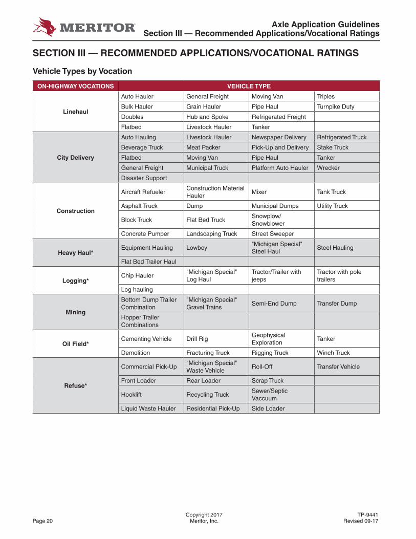
Vehicle Types by Vocation
ON-HIGHWAY VOCATIONS VEHICLE TYPE
Linehaul
Auto Hauler General Freight Moving Van Triples
Bulk Hauler Grain Hauler Pipe Haul Turnpike Duty
Doubles Hub and Spoke Refrigerated Freight
Flatbed Livestock Hauler Tanker
City Delivery
Auto Hauling Livestock Hauler Newspaper Delivery Refrigerated Truck
Beverage Truck Meat Packer Pick-Up and Delivery Stake Truck
Flatbed Moving Van Pipe Haul Tanker
General Freight Municipal Truck Platform Auto Hauler Wrecker
Disaster Support
Construction
Aircraft RefuelerConstruction Material Hauler
Mixer Tank Truck
Asphalt Truck Dump Municipal Dumps Utility Truck
Block Truck Flat Bed TruckSnowplow/Snowblower
Concrete Pumper Landscaping Truck Street Sweeper
Heavy Haul*Equipment Hauling Lowboy
"Michigan Special" Steel Haul
Steel Hauling
Flat Bed Trailer Haul
Logging*Chip Hauler
"Michigan Special" Log Haul
Tractor/Trailer with jeeps
Tractor with pole trailers
Log hauling
Mining
Bottom Dump TrailerCombination
"Michigan Special" Gravel Trains
Semi-End Dump Transfer Dump
Hopper Trailer Combinations
Oil Field*Cementing Vehicle Drill Rig
Geophysical Exploration
Tanker
Demolition Fracturing Truck Rigging Truck Winch Truck
Refuse*
Commercial Pick-Up"Michigan Special" Waste Vehicle
Roll-Off Transfer Vehicle
Front Loader Rear Loader Scrap Truck
Hooklift Recycling TruckSewer/Septic Vaccuum
Liquid Waste Hauler Residential Pick-Up Side Loader
Axle Application GuidelinesSection III — Recommended Applications/Vocational Ratings
TP-9441 Copyright 2017Revised 09-17 Meritor, Inc. Page 21
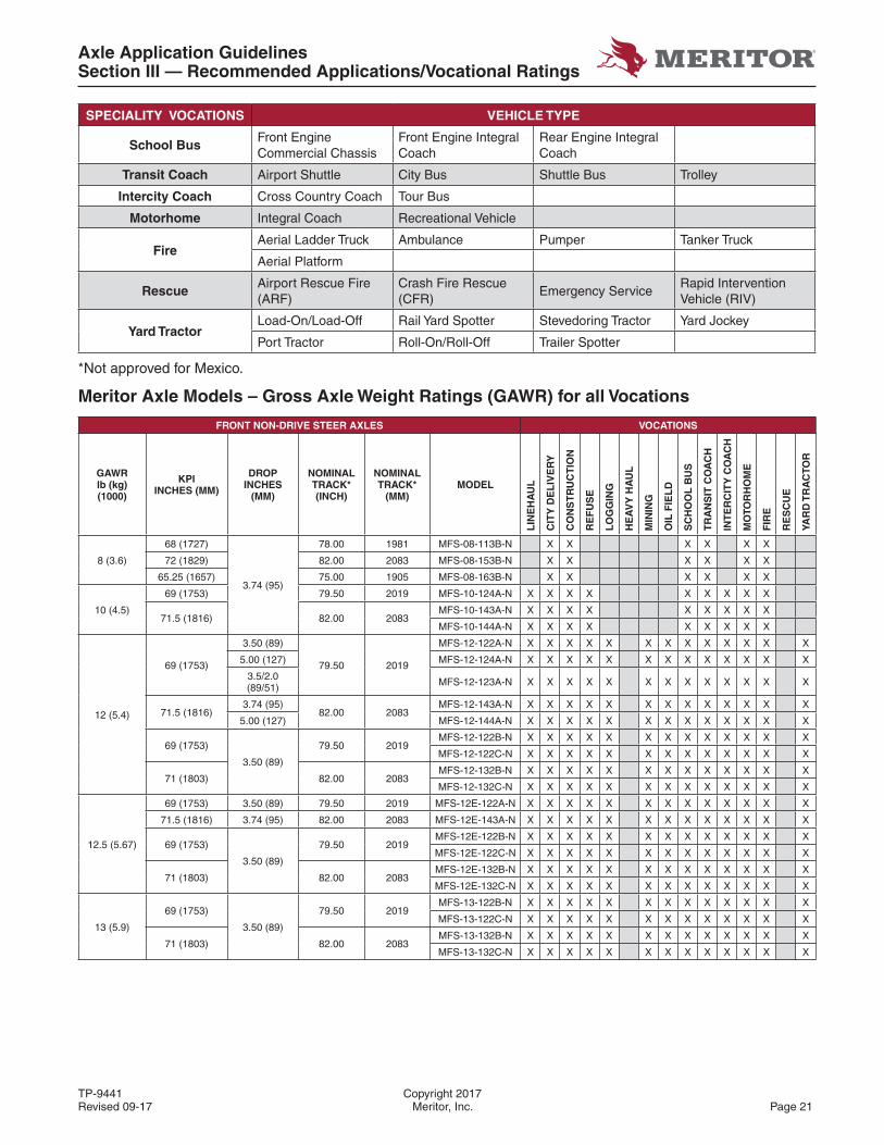
SPECIALITY VOCATIONS VEHICLE TYPE
School BusFront Engine Commercial Chassis
Front Engine Integral Coach
Rear Engine Integral Coach
Transit Coach Airport Shuttle City Bus Shuttle Bus Trolley
Intercity Coach Cross Country Coach Tour Bus
Motorhome Integral Coach Recreational Vehicle
FireAerial Ladder Truck Ambulance Pumper Tanker Truck
Aerial Platform
RescueAirport Rescue Fire (ARF)
Crash Fire Rescue (CFR)
Emergency ServiceRapid Intervention Vehicle (RIV)
Yard TractorLoad-On/Load-Off Rail Yard Spotter Stevedoring Tractor Yard Jockey
Port Tractor Roll-On/Roll-Off Trailer Spotter
*Not approved for Mexico.
Meritor Axle Models – Gross Axle Weight Ratings (GAWR) for all Vocations
FRONT NON-DRIVE STEER AXLES VOCATIONS
GAWR lb (kg) (1000)
KPI INCHES (MM)
DROP INCHES
(MM)
NOMINAL TRACK* (INCH)
NOMINAL TRACK*
(MM)MODEL
LIN
EH
AU
L
CIT
Y D
EL
IVE
RY
CO
NS
TR
UC
TIO
N
RE
FU
SE
LO
GG
ING
HE
AV
Y H
AU
L
MIN
ING
OIL
FIE
LD
SC
HO
OL
BU
S
TR
AN
SIT
CO
AC
H
INT
ER
CIT
Y C
OA
CH
MO
TOR
HO
ME
FIR
E
RE
SC
UE
YAR
D T
RA
CTO
R
8 (3.6)
68 (1727)
3.74 (95)
78.00 1981 MFS-08-113B-N X X X X X X
72 (1829) 82.00 2083 MFS-08-153B-N X X X X X X
65.25 (1657) 75.00 1905 MFS-08-163B-N X X X X X X
10 (4.5)
69 (1753) 79.50 2019 MFS-10-124A-N X X X X X X X X X
71.5 (1816) 82.00 2083MFS-10-143A-N X X X X X X X X X
MFS-10-144A-N X X X X X X X X X
12 (5.4)
69 (1753)
3.50 (89)
79.50 2019
MFS-12-122A-N X X X X X X X X X X X X X
5.00 (127) MFS-12-124A-N X X X X X X X X X X X X X
3.5/2.0 (89/51) MFS-12-123A-N X X X X X X X X X X X X X
71.5 (1816)3.74 (95)
82.00 2083MFS-12-143A-N X X X X X X X X X X X X X
5.00 (127) MFS-12-144A-N X X X X X X X X X X X X X
69 (1753)
3.50 (89)
79.50 2019MFS-12-122B-N X X X X X X X X X X X X X
MFS-12-122C-N X X X X X X X X X X X X X
71 (1803) 82.00 2083MFS-12-132B-N X X X X X X X X X X X X X
MFS-12-132C-N X X X X X X X X X X X X X
12.5 (5.67)
69 (1753) 3.50 (89) 79.50 2019 MFS-12E-122A-N X X X X X X X X X X X X X
71.5 (1816) 3.74 (95) 82.00 2083 MFS-12E-143A-N X X X X X X X X X X X X X
69 (1753)
3.50 (89)
79.50 2019MFS-12E-122B-N X X X X X X X X X X X X X
MFS-12E-122C-N X X X X X X X X X X X X X
71 (1803) 82.00 2083MFS-12E-132B-N X X X X X X X X X X X X X
MFS-12E-132C-N X X X X X X X X X X X X X
13 (5.9)
69 (1753)
3.50 (89)
79.50 2019MFS-13-122B-N X X X X X X X X X X X X X
MFS-13-122C-N X X X X X X X X X X X X X
71 (1803) 82.00 2083MFS-13-132B-N X X X X X X X X X X X X X
MFS-13-132C-N X X X X X X X X X X X X X
Axle Application GuidelinesSection III — Recommended Applications/Vocational Ratings
Copyright 2017 TP-9441Page 22 Meritor, Inc. Revised 09-17
FRONT NON-DRIVE STEER AXLES VOCATIONS
GAWR lb (kg) (1000)
KPI INCHES (MM)
DROP INCHES
(MM)
NOMINAL TRACK* (INCH)
NOMINAL TRACK*
(MM)MODEL
LIN
EH
AU
L
CIT
Y D
EL
IVE
RY
CO
NS
TR
UC
TIO
N
RE
FU
SE
LO
GG
ING
HE
AV
Y H
AU
L
MIN
ING
OIL
FIE
LD
SC
HO
OL
BU
S
TR
AN
SIT
CO
AC
H
INT
ER
CIT
Y C
OA
CH
MO
TOR
HO
ME
FIR
E
RE
SC
UE
YAR
D T
RA
CTO
R
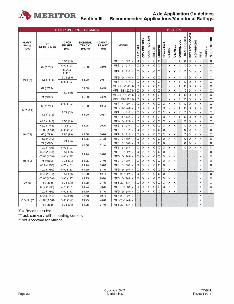
13.2 (6)
69 (1753)
3.50 (89)
79.50 2019
MFS-13-122A-N X X X X X X X X X X X X X
5.00 (127) MFS-13-124A-N X X X X X X X X X X X X X
3.5/2.0 (89/51) MFS-13-123A-N X X X X X X X X X X X X X
71.5 (1816)3.74 (95)
81.00 2057MFS-13-143A-N X X X X X X X X X X X X X
5.00 (127) MFS-13-144A-N X X X X X X X X X X X X X
69 (1753)
3.50 (89)
79.50 2019MFS-13B-122B-N X X X X X X X X X X X X X
MFS-13B-122C-N X X X X X X X X X X X X X
71 (1803) 82.00 2083MFS-13B-132B-N X X X X X X X X X X X X X
MFS-13B-132C-N X X X X X X X X X X X X X
14.7 (6.7)
69 (1753)5.00 (127)
78.50 1994MFS-14-122A-N X X X X X X X X X X X X X X
3.74 (95)
MFS-14-124A-N X X X X X X X X X X X X X X
71.5 (1816) 81.00 2057MFS-14-143A-N X X X X X X X X X X X X X X
MFS-14-144A-N X X X X X X X X X X X X X X
16 (7.3)
68.5 (1740) 3.50 (89)
81.75 2076
MFS-16-192A-N X X X X X X X X X X X X X
68.2 (1748) 4.76 (121) MFS-16-193A-N X X X X X X X X X X X X X
68.83 (1748) 5.00 (127) MFS-16-194A-N X X X X X X X X X X X X X
69 (1753) 3.50 (89) 82.25 2089 MFS-16-122A-N X X X X X X X X X X X X X
71.5 (1816)3.74 (95)
84.75 2153 MFS-16-143A-N X X X X X X X X X X X X X
71 (1803)84.25 2140
MFS-16-133A-N X X X X X X X X X X X X X
70.7 (1796) 5.00 (127) MFS-16-135A-N X X X X X X X X X X X X X
18 (8.2)
68.5 (1740) 3.50 (89)81.74 2076
MFS-18-192A-N X X X X X X X X X X
68.83 (1748) 5.00 (127) MFS-18-194A-N X X X X X X X X X X
71 (1803) 3.74 (95) 84.25 2140 MFS-18-133A-N X X X X X X X X X X
68.2 (1732) 4.76 (121) 81.74 2076 MFS-18-193A-N X X X X X X X X X X
70.7 (1796) 5.00 (127) 84.25 2140 MFS-18-135A-N X X X X X X X X X X
20 (9)
68.5 (1740) 3.50 (89) 78.50 1994 MFS-20-192A-N X X X X X X X X X X
68.83 (1748) 5.00 (127) 81.75 2076 MFS-20-194A-N X X X X X X X X X X
71 (1803) 3.74 (95) 84.25 2140 MFS-20-133A-N X X X X X X X X X X
68.2 (1732) 4.76 (121) 81.74 2076 MFS-18-193A-N X X X X X X X X X X
70.7 (1796) 5.00 (127) 84.25 2140 MFS-18-135A-N X X X X X X X X X X
21.5 (9.8)**
68.5 (1740) 3.50 (89) 78.50 1994 MFS-20-192A-N X
68.83 (1748) 5.00 (127) 81.75 2076 MFS-20-194A-N X
71 (1803) 3.74 (95) 84.25 2140 MFS-20-133A-N X
X = Recommended*Track can vary with mounting centers**Not approved for Mexico
Axle Application GuidelinesSection III — Recommended Applications/Vocational Ratings
TP-9441 Copyright 2017Revised 09-17 Meritor, Inc. Page 23
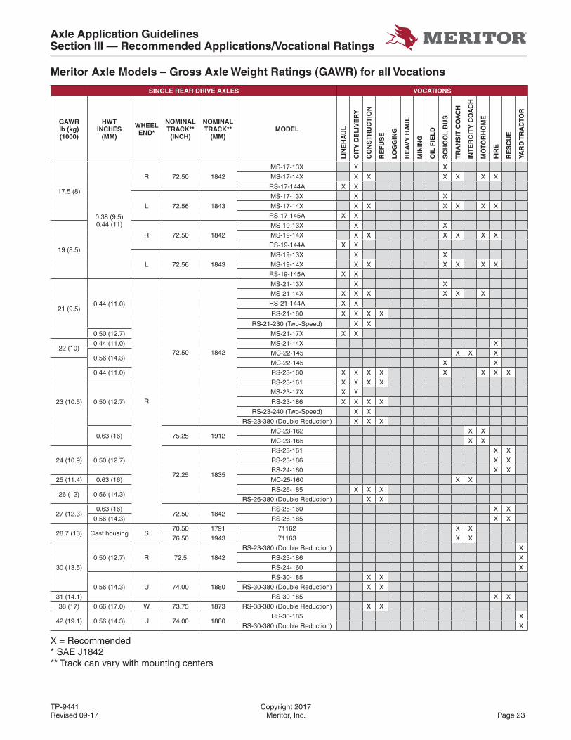
Meritor Axle Models – Gross Axle Weight Ratings (GAWR) for all Vocations
SINGLE REAR DRIVE AXLES VOCATIONS
GAWR lb (kg) (1000)
HWT INCHES
(MM)
WHEEL END*
NOMINAL TRACK**
(INCH)
NOMINAL TRACK**
(MM)MODEL
LIN
EH
AU
L
CIT
Y D
EL
IVE
RY
CO
NS
TR
UC
TIO
N
RE
FU
SE
LO
GG
ING
HE
AV
Y H
AU
L
MIN
ING
OIL
FIE
LD
SC
HO
OL
BU
S
TR
AN
SIT
CO
AC
H
INT
ER
CIT
Y C
OA
CH
MO
TOR
HO
ME
FIR
E
RE
SC
UE
YAR
D T
RA
CTO
R
17.5 (8)
0.38 (9.5) 0.44 (11)
R 72.50 1842
MS-17-13X X X
MS-17-14X X X X X X X
RS-17-144A X X
L 72.56 1843
MS-17-13X X X
MS-17-14X X X X X X X
RS-17-145A X X
19 (8.5)
R 72.50 1842
MS-19-13X X X
MS-19-14X X X X X X X
RS-19-144A X X
L 72.56 1843
MS-19-13X X X
MS-19-14X X X X X X X
RS-19-145A X X
21 (9.5)0.44 (11.0)
R
72.50 1842
MS-21-13X X X
MS-21-14X X X X X X X
RS-21-144A X X
RS-21-160 X X X X
RS-21-230 (Two-Speed) X X
0.50 (12.7) MS-21-17X X X
22 (10)0.44 (11.0) MS-21-14X X
0.56 (14.3)MC-22-145 X X X
23 (10.5)
MC-22-145 X X
0.44 (11.0) RS-23-160 X X X X X X X X
0.50 (12.7)
RS-23-161 X X X X
MS-23-17X X X
RS-23-186 X X X X
RS-23-240 (Two-Speed) X X
RS-23-380 (Double Reduction) X X X
0.63 (16) 75.25 1912MC-23-162 X X
MC-23-165 X X
24 (10.9) 0.50 (12.7)
72.25 1835
RS-23-161 X X
RS-23-186 X X
RS-24-160 X X
25 (11.4) 0.63 (16) MC-25-160 X X
26 (12) 0.56 (14.3)RS-26-185 X X X
RS-26-380 (Double Reduction) X X
27 (12.3)0.63 (16)
72.50 1842RS-25-160 X X
0.56 (14.3) RS-26-185 X X
28.7 (13) Cast housing S70.50 1791 71162 X X
76.50 1943 71163 X X
30 (13.5)
0.50 (12.7) R 72.5 1842
RS-23-380 (Double Reduction) X
RS-23-186 X
RS-24-160 X
0.56 (14.3) U 74.00 1880
RS-30-185 X X
RS-30-380 (Double Reduction) X X
31 (14.1) RS-30-185 X X
38 (17) 0.66 (17.0) W 73.75 1873 RS-38-380 (Double Reduction) X X
42 (19.1) 0.56 (14.3) U 74.00 1880RS-30-185 X
RS-30-380 (Double Reduction) X
X = Recommended* SAE J1842** Track can vary with mounting centers
Axle Application GuidelinesSection III — Recommended Applications/Vocational Ratings
Copyright 2017 TP-9441Page 24 Meritor, Inc. Revised 09-17
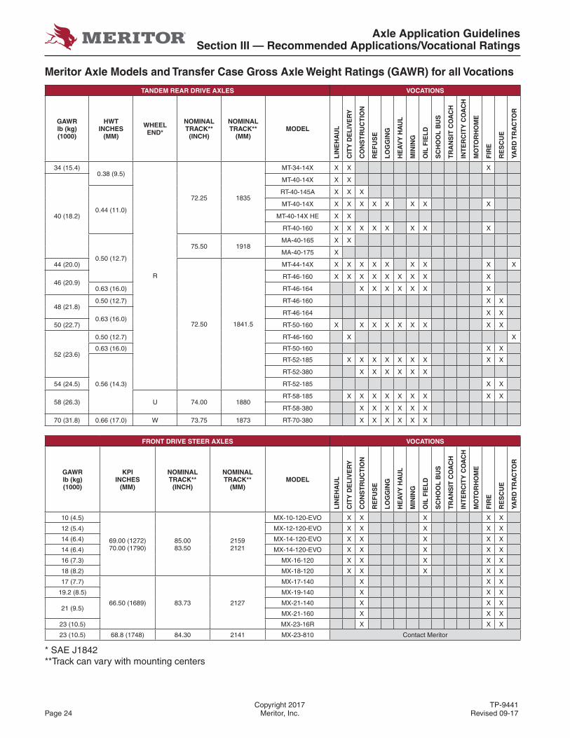
Meritor Axle Models and Transfer Case Gross Axle Weight Ratings (GAWR) for all Vocations
TANDEM REAR DRIVE AXLES VOCATIONS
GAWR lb (kg) (1000)
HWT INCHES
(MM)
WHEEL END*
NOMINAL TRACK**
(INCH)
NOMINAL TRACK**
(MM)MODEL
LIN
EH
AU
L
CIT
Y D
EL
IVE
RY
CO
NS
TR
UC
TIO
N
RE
FU
SE
LO
GG
ING
HE
AV
Y H
AU
L
MIN
ING
OIL
FIE
LD
SC
HO
OL
BU
S
TR
AN
SIT
CO
AC
H
INT
ER
CIT
Y C
OA
CH
MO
TOR
HO
ME
FIR
E
RE
SC
UE
YAR
D T
RA
CTO
R
34 (15.4)0.38 (9.5)
R
72.25 1835
MT-34-14X X X X
40 (18.2)
MT-40-14X X X
0.44 (11.0)
RT-40-145A X X X
MT-40-14X X X X X X X X X
MT-40-14X HE X X
RT-40-160 X X X X X X X X
0.50 (12.7)
75.50 1918MA-40-165 X X
MA-40-175 X
44 (20.0)
72.50 1841.5
MT-44-14X X X X X X X X X X
46 (20.9)RT-46-160 X X X X X X X X X
0.63 (16.0) RT-46-164 X X X X X X X
48 (21.8)0.50 (12.7) RT-46-160 X X
0.63 (16.0)RT-46-164 X X
50 (22.7) RT-50-160 X X X X X X X X X
52 (23.6)
0.50 (12.7) RT-46-160 X X
0.63 (16.0) RT-50-160 X X
0.56 (14.3)
RT-52-185 X X X X X X X X X
RT-52-380 X X X X X X
54 (24.5) RT-52-185 X X
58 (26.3) U 74.00 1880RT-58-185 X X X X X X X X X
RT-58-380 X X X X X X
70 (31.8) 0.66 (17.0) W 73.75 1873 RT-70-380 X X X X X X
FRONT DRIVE STEER AXLES VOCATIONS
GAWR lb (kg) (1000)
KPI INCHES
(MM)
NOMINAL TRACK**
(INCH)
NOMINAL TRACK**
(MM)MODEL
LIN
EH
AU
L
CIT
Y D
EL
IVE
RY
CO
NS
TR
UC
TIO
N
RE
FU
SE
LO
GG
ING
HE
AV
Y H
AU
L
MIN
ING
OIL
FIE
LD
SC
HO
OL
BU
S
TR
AN
SIT
CO
AC
H
INT
ER
CIT
Y C
OA
CH
MO
TOR
HO
ME
FIR
E
RE
SC
UE
YAR
D T
RA
CTO
R10 (4.5)
69.00 (1272)70.00 (1790)
85.0083.50
21592121
MX-10-120-EVO X X X X X
12 (5.4) MX-12-120-EVO X X X X X
14 (6.4) MX-14-120-EVO X X X X X
14 (6.4) MX-14-120-EVO X X X X X
16 (7.3) MX-16-120 X X X X X
18 (8.2) MX-18-120 X X X X X
17 (7.7)
66.50 (1689) 83.73 2127
MX-17-140 X X X
19.2 (8.5) MX-19-140 X X X
21 (9.5)MX-21-140 X X X
MX-21-160 X X X
23 (10.5) MX-23-16R X X X
23 (10.5) 68.8 (1748) 84.30 2141 MX-23-810 Contact Meritor
* SAE J1842**Track can vary with mounting centers
Axle Application GuidelinesSection III — Recommended Applications/Vocational Ratings
TP-9441 Copyright 2017Revised 09-17 Meritor, Inc. Page 25
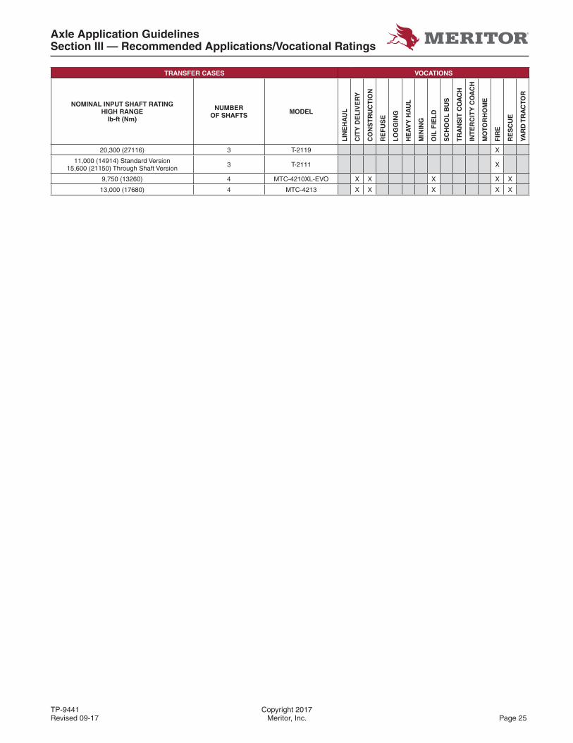
TRANSFER CASES VOCATIONS
NOMINAL INPUT SHAFT RATINGHIGH RANGE
lb-ft (Nm)
NUMBER OF SHAFTS MODEL
LIN
EH
AU
L
CIT
Y D
EL
IVE
RY
CO
NS
TR
UC
TIO
N
RE
FU
SE
LO
GG
ING
HE
AV
Y H
AU
L
MIN
ING
OIL
FIE
LD
SC
HO
OL
BU
S
TR
AN
SIT
CO
AC
H
INT
ER
CIT
Y C
OA
CH
MO
TOR
HO
ME
FIR
E
RE
SC
UE
YAR
D T
RA
CTO
R
20,300 (27116) 3 T-2119 X
11,000 (14914) Standard Version15,600 (21150) Through Shaft Version 3 T-2111 X
9,750 (13260) 4 MTC-4210XL-EVO X X X X X
13,000 (17680) 4 MTC-4213 X X X X X
Axle Application GuidelinesSection III — Recommended Applications/Vocational Ratings
Copyright 2017 TP-9441Page 26 Meritor, Inc. Revised 09-17
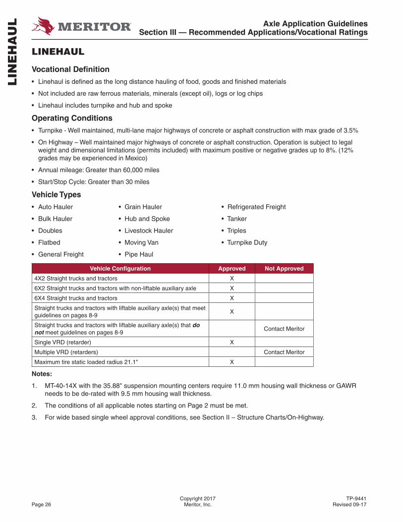
LINEHAUL
Vocational Defi nition
• Linehaul is defi ned as the long distance hauling of food, goods and fi nished materials
• Not included are raw ferrous materials, minerals (except oil), logs or log chips
• Linehaul includes turnpike and hub and spoke
Operating Conditions
• Turnpike - Well maintained, multi-lane major highways of concrete or asphalt construction with max grade of 3.5%
• On Highway – Well maintained major highways of concrete or asphalt construction. Operation is subject to legal weight and dimensional limitations (permits included) with maximum positive or negative grades up to 8%. (12% grades may be experienced in Mexico)
• Annual mileage: Greater than 60,000 miles
• Start/Stop Cycle: Greater than 30 miles
Vehicle Types
• Auto Hauler • Grain Hauler • Refrigerated Freight
• Bulk Hauler • Hub and Spoke • Tanker
• Doubles • Livestock Hauler • Triples
• Flatbed • Moving Van • Turnpike Duty
• General Freight • Pipe Haul
Vehicle Confi guration Approved Not Approved
4X2 Straight trucks and tractors X
6X2 Straight trucks and tractors with non-liftable auxiliary axle X
6X4 Straight trucks and tractors X
Straight trucks and tractors with liftable auxiliary axle(s) that meet guidelines on pages 8-9
X
Straight trucks and tractors with liftable auxiliary axle(s) that do not meet guidelines on pages 8-9
Contact Meritor
Single VRD (retarder) X
Multiple VRD (retarders) Contact Meritor
Maximum tire static loaded radius 21.1" X
Notes:
1. MT-40-14X with the 35.88" suspension mounting centers require 11.0 mm housing wall thickness or GAWR needs to be de-rated with 9.5 mm housing wall thickness.
2. The conditions of all applicable notes starting on Page 2 must be met.
3. For wide based single wheel approval conditions, see Section II – Structure Charts/On-Highway.
LIN
EH
AU
L
Axle Application GuidelinesSection III — Recommended Applications/Vocational Ratings
TP-9441 Copyright 2017Revised 09-17 Meritor, Inc. Page 27
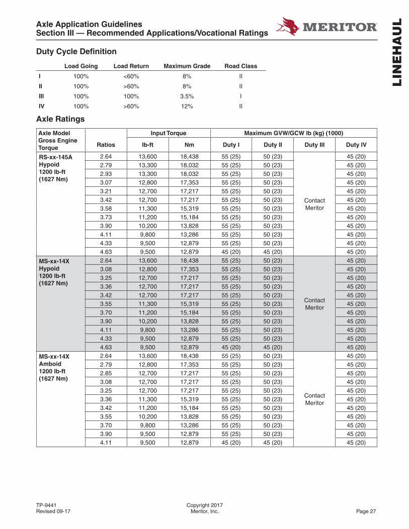
Duty Cycle Defi nition
Load Going Load Return Maximum Grade Road Class
I 100% <60% 8% II
II 100% >60% 8% II
III 100% 100% 3.5% I
IV 100% >60% 12% II
Axle Ratings
Axle Model Gross Engine Torque
Input Torque Maximum GVW/GCW lb (kg) (1000)
Ratios lb-ft Nm Duty I Duty II Duty III Duty IV
RS-xx-145A Hypoid 1200 lb-ft (1627 Nm)
2.64 13,600 18,438 55 (25) 50 (23)
ContactMeritor
45 (20)2.79 13,300 18,032 55 (25) 50 (23) 45 (20)2.93 13,300 18,032 55 (25) 50 (23) 45 (20)3.07 12,800 17,353 55 (25) 50 (23) 45 (20)3.21 12,700 17,217 55 (25) 50 (23) 45 (20)3.42 12,700 17,217 55 (25) 50 (23) 45 (20)3.58 11,300 15,319 55 (25) 50 (23) 45 (20)3.73 11,200 15,184 55 (25) 50 (23) 45 (20)3.90 10,200 13,828 55 (25) 50 (23) 45 (20)4.11 9,800 13,286 55 (25) 50 (23) 45 (20)4.33 9,500 12,879 55 (25) 50 (23) 45 (20)4.63 9,500 12,879 45 (20) 45 (20) 45 (20)
MS-xx-14X Hypoid 1200 lb-ft (1627 Nm)
2.64 13,600 18,438 55 (25) 50 (23)
ContactMeritor
45 (20)3.08 12,800 17,353 55 (25) 50 (23) 45 (20)3.25 12,700 17,217 55 (25) 50 (23) 45 (20)3.36 12,700 17,217 55 (25) 50 (23) 45 (20)3.42 12,700 17,217 55 (25) 50 (23) 45 (20)3.55 11,300 15,319 55 (25) 50 (23) 45 (20)3.70 11,200 15,184 55 (25) 50 (23) 45 (20)3.90 10,200 13,828 55 (25) 50 (23) 45 (20)4.11 9,800 13,286 55 (25) 50 (23) 45 (20)4.33 9,500 12,879 55 (25) 50 (23) 45 (20)4.63 9,500 12,879 45 (20) 45 (20) 45 (20)
MS-xx-14X Amboid 1200 lb-ft (1627 Nm)
2.64 13,600 18,438 55 (25) 50 (23)
ContactMeritor
45 (20)2.79 12,800 17,353 55 (25) 50 (23) 45 (20)2.85 12,700 17,217 55 (25) 50 (23) 45 (20)3.08 12,700 17,217 55 (25) 50 (23) 45 (20)3.25 12,700 17,217 55 (25) 50 (23) 45 (20)3.36 11,300 15,319 55 (25) 50 (23) 45 (20)3.42 11,200 15,184 55 (25) 50 (23) 45 (20)3.55 10,200 13,828 55 (25) 50 (23) 45 (20)3.70 9,800 13,286 55 (25) 50 (23) 45 (20)3.90 9,500 12,879 55 (25) 50 (23) 45 (20)4.11 9,500 12,879 45 (20) 45 (20) 45 (20)
LIN
EH
AU
L

Axle Application GuidelinesSection III — Recommended Applications/Vocational Ratings
Copyright 2017 TP-9441Page 28 Meritor, Inc. Revised 09-17
Axle Model Gross Engine Torque
Input Torque Maximum GVW/GCW lb (kg) (1000)
Ratios lb-ft Nm Duty I Duty II Duty III Duty IV
RS-xx-160/11850 lb-ft(2508 Nm)
2.50 22,500 30,506 90 (41) 80 (36)
ContactMeritor
70 (32)
2.67 22,500 30,506 90 (41) 80 (36) 70 (32)
2.80 22,500 30,506 90 (41) 80 (36) 70 (32)
2.93 22,500 30,506 90 (41) 80 (36) 70 (32)
3.07 22,500 30,506 90 (41) 80 (36) 70 (32)
3.21 22,500 30,506 90 (41) 80 (36) 70 (32)
3.42 22,500 30,506 90 (41) 80 (36) 70 (32)
3.58 20,800 28,201 90 (41) 80 (36) 70 (32)
3.73 20,800 28,201 90 (41) 80 (36) 70 (32)
3.91 20,800 28,201 90 (41) 80 (36) 70 (32)
4.10 20,800 28,201 90 (41) 80 (36) 70 (32)
4.30 20,800 28,201 90 (41) 80 (36) 70 (32)
4.56 20,800 28,201 90 (41) 80 (36) 70 (32)
MS-xx-17X1850 lb-ft(2508 Nm)
2.31 24,000 32,600 115 (32) 90 (41) 110 (50)
ContactMeritor
2.47 24,000 32,600 120 (54.5) 100 (45) 140 (63.5)
2.64 24,000 32,600 120 (54.5) 100 (45) 140 (63.5)
2.85 24,000 32,600 120 (54.5) 100 (45) 140 (63.5)
3.08 24,000 32,600 120 (54.5) 100 (45) 130 (59)
3.36 24,000 32,600 120 (54.5) 100 (45) 130 (59)
RS-xx-18X1850 lb-ft(2508 Nm)
3.42 25,000 33,895 125 (57) 110 (50) 140 (63.5) 90 (41)
3.58 22,100 29,963 125 (57) 110 (50) 140 (63.5) 90 (41)
3.73 22,100 29,963 125 (57) 110 (50) 140 (63.5) 90 (41)
4.30 22,100 29,963 115 (62) 105 (48) 140 (63.5) 90 (41)
4.56 22,100 29,963 115 (62) 100 (45) 140 (63.5) 90 (41)
MT-xx-14X HE1850 lb-ft(2508 Nm)
2.15 24,000 32,537 80 (36) 80 (36) 80 (36) X
2.28 24,000 32,537 80 (36) 80 (36) 80 (36) X
2.47 24,000 32,537 95 (43) 90 (41) 105 (47) X
2.64 24,000 32,537 95 (43) 90 (41) 105 (47) X
2.79 24,000 32,537 95 (43) 90 (41) 105 (47) X
2.85 24,000 32,537 95 (43) 90 (41) 105 (47) X
2.93 24,000 32,537 95 (43) 90 (41) 105 (47) X
3.08 24,000 32,537 95 (43) 90 (41) 105 (47) X
3.25 24,000 32,537 95 (43) 90 (41) 105 (47) X
3.36 24,000 32,537 95 (43) 90 (41) 105 (47) X
3.42 24,000 32,537 95 (43) 90 (41) 105 (47) X
3.55 22,100 29,961 95 (43) 90 (41) 105 (47) X
3.70 22,100 29,961 95 (43) 90 (41) 105 (47) X
3.90 22,100 29,961 95 (43) 90 (41) 105 (47) X
LIN
EH
AU
L
Axle Application GuidelinesSection III — Recommended Applications/Vocational Ratings
TP-9441 Copyright 2017Revised 09-17 Meritor, Inc. Page 29
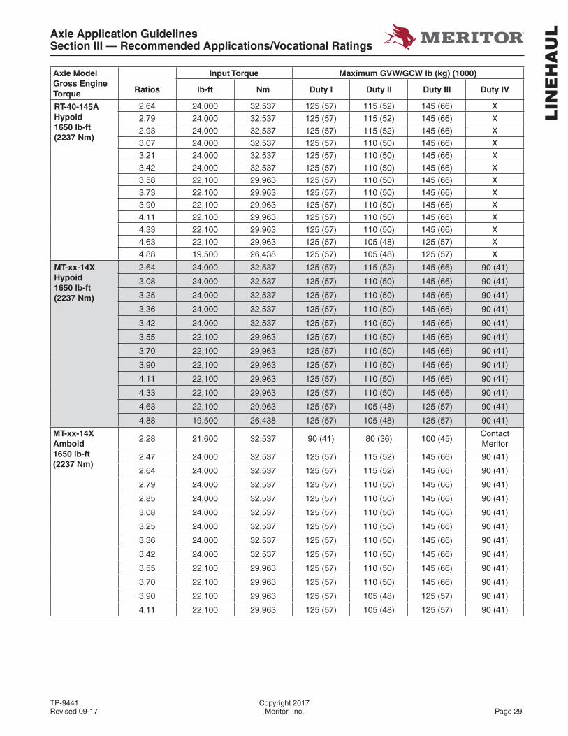
Axle Model Gross Engine Torque
Input Torque Maximum GVW/GCW lb (kg) (1000)
Ratios lb-ft Nm Duty I Duty II Duty III Duty IV
RT-40-145AHypoid1650 lb-ft(2237 Nm)
2.64 24,000 32,537 125 (57) 115 (52) 145 (66) X
2.79 24,000 32,537 125 (57) 115 (52) 145 (66) X
2.93 24,000 32,537 125 (57) 115 (52) 145 (66) X
3.07 24,000 32,537 125 (57) 110 (50) 145 (66) X
3.21 24,000 32,537 125 (57) 110 (50) 145 (66) X
3.42 24,000 32,537 125 (57) 110 (50) 145 (66) X
3.58 22,100 29,963 125 (57) 110 (50) 145 (66) X
3.73 22,100 29,963 125 (57) 110 (50) 145 (66) X
3.90 22,100 29,963 125 (57) 110 (50) 145 (66) X
4.11 22,100 29,963 125 (57) 110 (50) 145 (66) X
4.33 22,100 29,963 125 (57) 110 (50) 145 (66) X
4.63 22,100 29,963 125 (57) 105 (48) 125 (57) X
4.88 19,500 26,438 125 (57) 105 (48) 125 (57) X
MT-xx-14XHypoid1650 lb-ft(2237 Nm)
2.64 24,000 32,537 125 (57) 115 (52) 145 (66) 90 (41)
3.08 24,000 32,537 125 (57) 110 (50) 145 (66) 90 (41)
3.25 24,000 32,537 125 (57) 110 (50) 145 (66) 90 (41)
3.36 24,000 32,537 125 (57) 110 (50) 145 (66) 90 (41)
3.42 24,000 32,537 125 (57) 110 (50) 145 (66) 90 (41)
3.55 22,100 29,963 125 (57) 110 (50) 145 (66) 90 (41)
3.70 22,100 29,963 125 (57) 110 (50) 145 (66) 90 (41)
3.90 22,100 29,963 125 (57) 110 (50) 145 (66) 90 (41)
4.11 22,100 29,963 125 (57) 110 (50) 145 (66) 90 (41)
4.33 22,100 29,963 125 (57) 110 (50) 145 (66) 90 (41)
4.63 22,100 29,963 125 (57) 105 (48) 125 (57) 90 (41)
4.88 19,500 26,438 125 (57) 105 (48) 125 (57) 90 (41)
MT-xx-14XAmboid1650 lb-ft(2237 Nm)
2.28 21,600 32,537 90 (41) 80 (36) 100 (45)Contact Meritor
2.47 24,000 32,537 125 (57) 115 (52) 145 (66) 90 (41)
2.64 24,000 32,537 125 (57) 115 (52) 145 (66) 90 (41)
2.79 24,000 32,537 125 (57) 110 (50) 145 (66) 90 (41)
2.85 24,000 32,537 125 (57) 110 (50) 145 (66) 90 (41)
3.08 24,000 32,537 125 (57) 110 (50) 145 (66) 90 (41)
3.25 24,000 32,537 125 (57) 110 (50) 145 (66) 90 (41)
3.36 24,000 32,537 125 (57) 110 (50) 145 (66) 90 (41)
3.42 24,000 32,537 125 (57) 110 (50) 145 (66) 90 (41)
3.55 22,100 29,963 125 (57) 110 (50) 145 (66) 90 (41)
3.70 22,100 29,963 125 (57) 110 (50) 145 (66) 90 (41)
3.90 22,100 29,963 125 (57) 105 (48) 125 (57) 90 (41)
4.11 22,100 29,963 125 (57) 105 (48) 125 (57) 90 (41)
LIN
EH
AU
L
Axle Application GuidelinesSection III — Recommended Applications/Vocational Ratings
Copyright 2017 TP-9441Page 30 Meritor, Inc. Revised 09-17
Axle Model Gross Engine Torque
Input Torque Maximum GVW/GCW lb (kg) (1000)
Ratios lb-ft Nm Duty I Duty II Duty III Duty IV
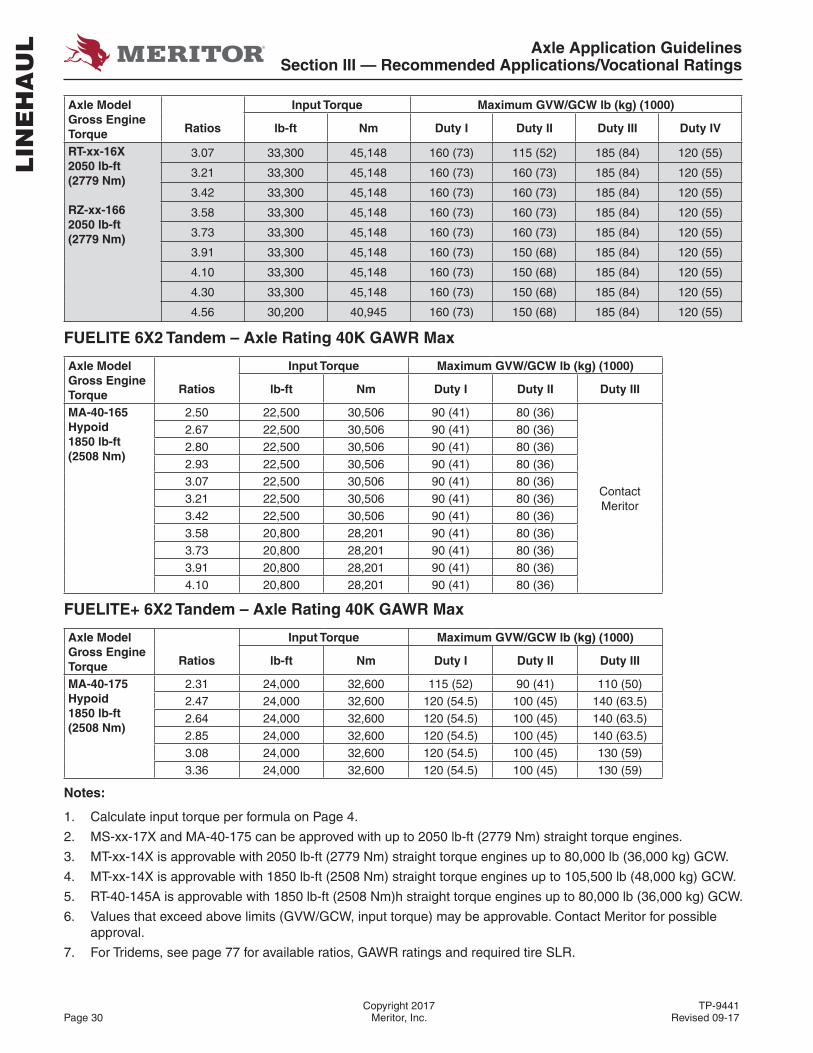
RT-xx-16X2050 lb-ft(2779 Nm)
RZ-xx-1662050 lb-ft(2779 Nm)
3.07 33,300 45,148 160 (73) 115 (52) 185 (84) 120 (55)
3.21 33,300 45,148 160 (73) 160 (73) 185 (84) 120 (55)
3.42 33,300 45,148 160 (73) 160 (73) 185 (84) 120 (55)
3.58 33,300 45,148 160 (73) 160 (73) 185 (84) 120 (55)
3.73 33,300 45,148 160 (73) 160 (73) 185 (84) 120 (55)
3.91 33,300 45,148 160 (73) 150 (68) 185 (84) 120 (55)
4.10 33,300 45,148 160 (73) 150 (68) 185 (84) 120 (55)
4.30 33,300 45,148 160 (73) 150 (68) 185 (84) 120 (55)
4.56 30,200 40,945 160 (73) 150 (68) 185 (84) 120 (55)
FUELITE 6X2 Tandem – Axle Rating 40K GAWR Max
Axle Model Gross Engine Torque
Input Torque Maximum GVW/GCW lb (kg) (1000)
Ratios lb-ft Nm Duty I Duty II Duty III
MA-40-165Hypoid1850 lb-ft(2508 Nm)
2.50 22,500 30,506 90 (41) 80 (36)
ContactMeritor
2.67 22,500 30,506 90 (41) 80 (36)2.80 22,500 30,506 90 (41) 80 (36)2.93 22,500 30,506 90 (41) 80 (36)3.07 22,500 30,506 90 (41) 80 (36)3.21 22,500 30,506 90 (41) 80 (36)3.42 22,500 30,506 90 (41) 80 (36)3.58 20,800 28,201 90 (41) 80 (36)3.73 20,800 28,201 90 (41) 80 (36)3.91 20,800 28,201 90 (41) 80 (36)4.10 20,800 28,201 90 (41) 80 (36)
FUELITE+ 6X2 Tandem – Axle Rating 40K GAWR Max
Axle Model Gross Engine Torque
Input Torque Maximum GVW/GCW lb (kg) (1000)
Ratios lb-ft Nm Duty I Duty II Duty III
MA-40-175Hypoid1850 lb-ft(2508 Nm)
2.31 24,000 32,600 115 (52) 90 (41) 110 (50)2.47 24,000 32,600 120 (54.5) 100 (45) 140 (63.5)2.64 24,000 32,600 120 (54.5) 100 (45) 140 (63.5)2.85 24,000 32,600 120 (54.5) 100 (45) 140 (63.5)3.08 24,000 32,600 120 (54.5) 100 (45) 130 (59)3.36 24,000 32,600 120 (54.5) 100 (45) 130 (59)
Notes:
1. Calculate input torque per formula on Page 4.
2. MS-xx-17X and MA-40-175 can be approved with up to 2050 lb-ft (2779 Nm) straight torque engines.
3. MT-xx-14X is approvable with 2050 lb-ft (2779 Nm) straight torque engines up to 80,000 lb (36,000 kg) GCW.
4. MT-xx-14X is approvable with 1850 lb-ft (2508 Nm) straight torque engines up to 105,500 lb (48,000 kg) GCW.
5. RT-40-145A is approvable with 1850 lb-ft (2508 Nm)h straight torque engines up to 80,000 lb (36,000 kg) GCW.
6. Values that exceed above limits (GVW/GCW, input torque) may be approvable. Contact Meritor for possible approval.
7. For Tridems, see page 77 for available ratios, GAWR ratings and required tire SLR.
LIN
EH
AU
L
Axle Application GuidelinesSection III — Recommended Applications/Vocational Ratings
TP-9441 Copyright 2017Revised 09-17 Meritor, Inc. Page 31
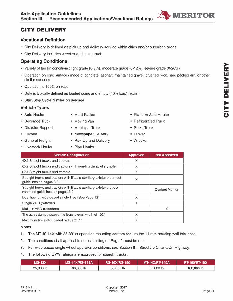
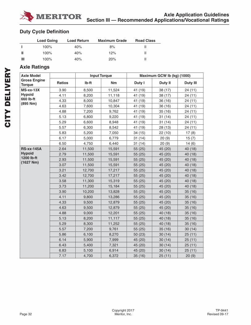
CITY DELIVERY
Vocational Defi nition
• City Delivery is defi ned as pick-up and delivery service within cities and/or suburban areas
• City Delivery includes wrecker and stake truck
Operating Conditions
• Variety of terrain conditions: light grade (0-8%), moderate grade (0-12%), severe grade (0-20%)
• Operation on road surfaces made of concrete, asphalt, maintained gravel, crushed rock, hard packed dirt, or other similar surfaces
• Operation is 100% on-road
• Duty is typically defi ned as loaded going and empty (40% load) return
• Start/Stop Cycle: 3 miles on average
Vehicle Types
• Auto Hauler • Meat Packer • Platform Auto Hauler
• Beverage Truck • Moving Van • Refrigerated Truck
• Disaster Support • Municipal Truck • Stake Truck
• Flatbed • Newspaper Delivery • Tanker
• General Freight • Pick-Up and Delivery • Wrecker
• Livestock Hauler • Pipe Hauler
Vehicle Confi guration Approved Not Approved
4X2 Straight trucks and tractors X
6X2 Straight trucks and tractors with non-liftable auxiliary axle X
6X4 Straight trucks and tractors X
Straight trucks and tractors with liftable auxiliary axle(s) that meet guidelines on pages 8-9
X
Straight trucks and tractors with liftable auxiliary axle(s) that do not meet guidelines on pages 8-9
Contact Meritor
DualTrac for wide-based single tires (See Page 12) X
Single VRD (retarder) X
Multiple VRD (retarders) X
The axles do not exceed the legal overall width of 102" X
Maximum tire static loaded radius 21.1" X
Notes:
1. The MT-40-14X with 35.88" suspension mounting centers require the 11 mm housing wall thickness.
2. The conditions of all applicable notes starting on Page 2 must be met.
3. For wide based single wheel approval conditions, see Section II – Structure Charts/On-Highway.
4. The following GVW ratings are approved for straight trucks:
MS-13X MS-14X/RS-145A RS-16X/RS-180 MT-14X/RT-145A RT-160/RT-180
25,000 lb 33,000 lb 50,000 lb 68,000 lb 100,000 lb
CIT
Y D
EL
IVE
RY
Axle Application GuidelinesSection III — Recommended Applications/Vocational Ratings
Copyright 2017 TP-9441Page 32 Meritor, Inc. Revised 09-17
Duty Cycle Defi nition
Load Going Load Return Maximum Grade Road Class
I 100% 40% 8% II
II 100% 40% 12% II
III 100% 40% 20% II
Axle Ratings
Axle Model Gross Engine Torque
Input Torque Maximum GCW lb (kg) (1000)
Ratios lb-ft Nm Duty I Duty II Duty III
MS-xx-13X Hypoid 660 lb-ft (895 Nm)
3.90 8,500 11,524 41 (19) 38 (17) 24 (11)
4.11 8,200 11,118 41 (19) 38 (17) 24 (11)
4.33 8,000 10,847 41 (19) 36 (16) 24 (11)
4.63 7,600 10,304 41 (19) 36 (16) 24 (11)
4.88 7,200 9,762 41 (19) 35 (16) 24 (11)
5.13 6,800 9,220 41 (19) 31 (14) 24 (11)
5.29 6,600 8,948 41 (19) 31 (14) 24 (11)
5.57 6,300 8,542 41 (19) 28 (13) 24 (11)
5.83 5,200 7,050 34 (15) 22 (10) 17 (8)
6.17 5,000 6,779 31 (14) 20 (9) 15 (7)
6.50 4,750 6,440 31 (14) 20 (9) 14 (6)RS-xx-145AHypoid1200 lb-ft(1627 Nm)
2.64 11,500 15,591 55 (25) 45 (20) 40 (18)
2.79 11,500 15,591 55 (25) 45 (20) 40 (18)
2.93 11,500 15,591 55 (25) 45 (20) 40 (18)
3.07 11,500 15,591 55 (25) 45 (20) 40 (18)
3.21 12,700 17,217 55 (25) 45 (20) 40 (18)
3.42 12,700 17,217 55 (25) 45 (20) 40 (18)
3.58 11,300 15,319 55 (25) 45 (20) 40 (18)
3.73 11,200 15,184 55 (25) 45 (20) 40 (18)
3.90 10,200 13,828 55 (25) 45 (20) 35 (16)
4.11 9,800 13,286 55 (25) 45 (20) 35 (16)
4.33 9,500 12,879 55 (25) 45 (20) 35 (16)
4.63 9,500 12,879 55 (25) 45 (20) 35 (16)
4.88 9,000 12,201 55 (25) 40 (18) 35 (16)
5.13 8,200 11,117 55 (25) 40 (18) 35 (16)
5.29 8,300 11,252 55 (25) 40 (18) 35 (16)
5.57 7,200 9,761 55 (25) 35 (16) 30 (14)
5.86 6,100 8,270 50 (23) 30 (14) 25 (11)
6.14 5,900 7,999 45 (20) 30 (14) 25 (11)
6.43 5,400 7,321 45 (20) 30 (14) 25 (11)
6.83 5,100 6,914 45 (20) 30 (14) 25 (11)
7.17 4,700 6,372 35 (16) 25 (11) 20 (9)
CIT
Y D
EL
IVE
RY
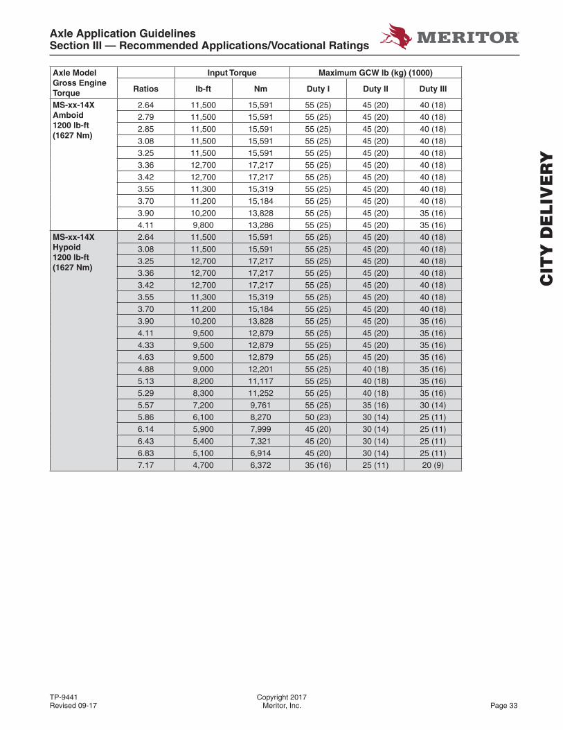
Axle Application GuidelinesSection III — Recommended Applications/Vocational Ratings
TP-9441 Copyright 2017Revised 09-17 Meritor, Inc. Page 33
Axle Model Gross Engine Torque
Input Torque Maximum GCW lb (kg) (1000)
Ratios lb-ft Nm Duty I Duty II Duty III
MS-xx-14X Amboid 1200 lb-ft (1627 Nm)
2.64 11,500 15,591 55 (25) 45 (20) 40 (18)
2.79 11,500 15,591 55 (25) 45 (20) 40 (18)
2.85 11,500 15,591 55 (25) 45 (20) 40 (18)
3.08 11,500 15,591 55 (25) 45 (20) 40 (18)
3.25 11,500 15,591 55 (25) 45 (20) 40 (18)
3.36 12,700 17,217 55 (25) 45 (20) 40 (18)
3.42 12,700 17,217 55 (25) 45 (20) 40 (18)
3.55 11,300 15,319 55 (25) 45 (20) 40 (18)
3.70 11,200 15,184 55 (25) 45 (20) 40 (18)
3.90 10,200 13,828 55 (25) 45 (20) 35 (16)
4.11 9,800 13,286 55 (25) 45 (20) 35 (16)MS-xx-14X Hypoid 1200 lb-ft (1627 Nm)
2.64 11,500 15,591 55 (25) 45 (20) 40 (18)
3.08 11,500 15,591 55 (25) 45 (20) 40 (18)3.25 12,700 17,217 55 (25) 45 (20) 40 (18)3.36 12,700 17,217 55 (25) 45 (20) 40 (18)
3.42 12,700 17,217 55 (25) 45 (20) 40 (18)
3.55 11,300 15,319 55 (25) 45 (20) 40 (18)
3.70 11,200 15,184 55 (25) 45 (20) 40 (18)
3.90 10,200 13,828 55 (25) 45 (20) 35 (16)
4.11 9,500 12,879 55 (25) 45 (20) 35 (16)
4.33 9,500 12,879 55 (25) 45 (20) 35 (16)
4.63 9,500 12,879 55 (25) 45 (20) 35 (16)
4.88 9,000 12,201 55 (25) 40 (18) 35 (16)
5.13 8,200 11,117 55 (25) 40 (18) 35 (16)
5.29 8,300 11,252 55 (25) 40 (18) 35 (16)
5.57 7,200 9,761 55 (25) 35 (16) 30 (14)
5.86 6,100 8,270 50 (23) 30 (14) 25 (11)
6.14 5,900 7,999 45 (20) 30 (14) 25 (11)
6.43 5,400 7,321 45 (20) 30 (14) 25 (11)
6.83 5,100 6,914 45 (20) 30 (14) 25 (11)
7.17 4,700 6,372 35 (16) 25 (11) 20 (9)
CIT
Y D
EL
IVE
RY

Axle Application GuidelinesSection III — Recommended Applications/Vocational Ratings
Copyright 2017 TP-9441Page 34 Meritor, Inc. Revised 09-17
Axle Model Gross Engine Torque
Input Torque Maximum GCW lb (kg) (1000)
Ratios lb-ft Nm Duty I Duty II Duty III
RS-xx-160/11850 lb-ft(2508 Nm)
2.67 21,000 28,472 80 (36) 70 (32) 55 (25)2.80 21,000 28,472 80 (36) 70 (32) 55 (25)2.93 21,000 28,472 80 (36) 70 (32) 55 (25)3.07 21,000 28,472 80 (36) 70 (32) 55 (25)3.21 21,000 28,472 80 (36) 70 (32) 55 (25)3.42 21,000 28,472 80 (36) 70 (32) 55 (25)3.58 20,800 28,201 80 (36) 65 (29) 55 (25)3.73 20,800 28,201 80 (36) 65 (29) 55 (25)3.91 20,800 28,201 80 (36) 65 (29) 55 (25)4.10 20,800 28,201 80 (36) 65 (29) 55 (25)4.30 19,100 25,896 80 (36) 65 (29) 55 (25)4.56 17,400 23,591 80 (36) 65 (29) 55 (25)4.89 15,500 21,015 80 (36) 55 (25) 45 (20)5.13 14,300 19,388 80 (36) 55 (25) 45 (20)5.38 13,100 17,761 80 (36) 55 (25) 45 (20)5.63 11,500 15,592 80 (36) 55 (25) 45 (20)6.14 10,200 13,829 80 (36) 50 (23) 40 (18)6.43 8,900 12,067 70 (32) 50 (23) 40 (18)6.83 8,900 12,067 70 (32) 50 (23) 40 (18)7.17 8,000 10,846 65 (29) 45 (20) 30 (14)
RS-xx-185/61850 lb-ft(2508 Nm)
3.42 23,000 31,183 110 (50) 80 (36) 55 (25)3.58 22,100 29,963 110 (50) 80 (36) 55 (25)3.73 22,100 29,963 110 (50) 80 (36) 55 (25)4.30 20,300 27,523 110 (50) 80 (36) 55 (25)4.56 19,500 26,438 105 (48) 80 (36) 55 (25)4.89 15,800 21,422 105 (48) 80 (36) 55 (25)5.13 16,900 22,913 100 (45) 80 (36) 55 (25)5.38 15,200 20,608 100 (45) 80 (36) 55 (25)5.63 12,900 17,490 80 (36) 70 (32) 55 (25)5.86 14,200 19,252 80 (36) 70 (32) 55 (25)6.14 12,000 16,270 70 (32) 70 (32) 55 (25)6.83 10,200 13,829 70 (32) 70 (32) 55 (25)7.17 9,200 12,473 70 (32) 70 (32) 45 (20)
MT-xx-14X HE1850 lb-ft(2508 Nm)
2.64 23,000 31,181 90 (41) 80 (36) 70 (32)2.79 23,000 31,181 90 (41) 80 (36) 70 (32)2.85 23,000 31,181 90 (41) 80 (36) 65 (29)2.93 23,000 31,181 85 (39) 80 (36) 65 (29)3.08 23,000 31,181 85 (39) 80 (36) 65 (29)3.25 23,000 31,181 85 (39) 80 (36) 65 (29)3.36 23,000 31,181 85 (39) 80 (36) 65 (29)3.42 23,000 31,181 80 (36) 80 (36) 65 (29)3.55 22,100 29,961 80 (36) 80 (36) 65 (29)3.70 22,100 29,961 80 (36) 80 (36) 65 (29)3.90 22,100 29,961 80 (36) 80 (36) 65 (29)
CIT
Y D
EL
IVE
RY
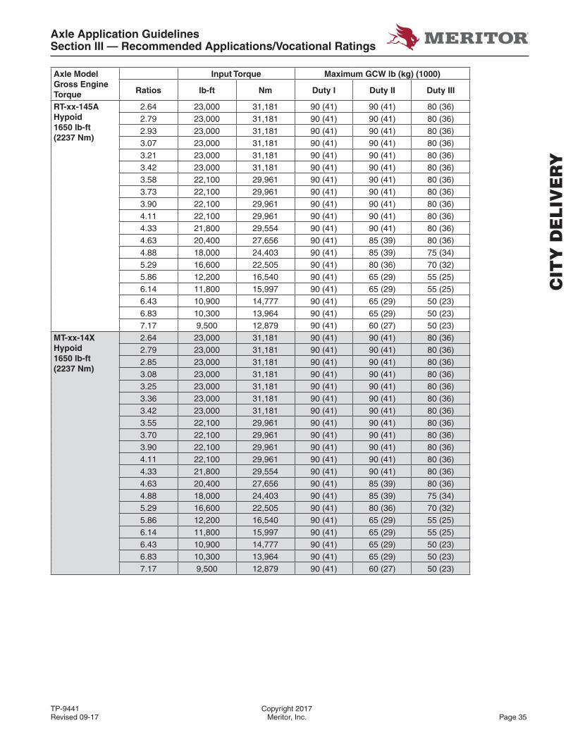
Axle Application GuidelinesSection III — Recommended Applications/Vocational Ratings
TP-9441 Copyright 2017Revised 09-17 Meritor, Inc. Page 35
Axle Model Gross Engine Torque
Input Torque Maximum GCW lb (kg) (1000)
Ratios lb-ft Nm Duty I Duty II Duty III
RT-xx-145AHypoid1650 lb-ft(2237 Nm)
2.64 23,000 31,181 90 (41) 90 (41) 80 (36)2.79 23,000 31,181 90 (41) 90 (41) 80 (36)2.93 23,000 31,181 90 (41) 90 (41) 80 (36)3.07 23,000 31,181 90 (41) 90 (41) 80 (36)3.21 23,000 31,181 90 (41) 90 (41) 80 (36)3.42 23,000 31,181 90 (41) 90 (41) 80 (36)3.58 22,100 29,961 90 (41) 90 (41) 80 (36)3.73 22,100 29,961 90 (41) 90 (41) 80 (36)3.90 22,100 29,961 90 (41) 90 (41) 80 (36)4.11 22,100 29,961 90 (41) 90 (41) 80 (36)4.33 21,800 29,554 90 (41) 90 (41) 80 (36)4.63 20,400 27,656 90 (41) 85 (39) 80 (36)4.88 18,000 24,403 90 (41) 85 (39) 75 (34)5.29 16,600 22,505 90 (41) 80 (36) 70 (32)5.86 12,200 16,540 90 (41) 65 (29) 55 (25)6.14 11,800 15,997 90 (41) 65 (29) 55 (25)6.43 10,900 14,777 90 (41) 65 (29) 50 (23)6.83 10,300 13,964 90 (41) 65 (29) 50 (23)7.17 9,500 12,879 90 (41) 60 (27) 50 (23)
MT-xx-14XHypoid1650 lb-ft(2237 Nm)
2.64 23,000 31,181 90 (41) 90 (41) 80 (36)2.79 23,000 31,181 90 (41) 90 (41) 80 (36)2.85 23,000 31,181 90 (41) 90 (41) 80 (36)3.08 23,000 31,181 90 (41) 90 (41) 80 (36)3.25 23,000 31,181 90 (41) 90 (41) 80 (36)3.36 23,000 31,181 90 (41) 90 (41) 80 (36)3.42 23,000 31,181 90 (41) 90 (41) 80 (36)3.55 22,100 29,961 90 (41) 90 (41) 80 (36)3.70 22,100 29,961 90 (41) 90 (41) 80 (36)3.90 22,100 29,961 90 (41) 90 (41) 80 (36)4.11 22,100 29,961 90 (41) 90 (41) 80 (36)4.33 21,800 29,554 90 (41) 90 (41) 80 (36)4.63 20,400 27,656 90 (41) 85 (39) 80 (36)4.88 18,000 24,403 90 (41) 85 (39) 75 (34)5.29 16,600 22,505 90 (41) 80 (36) 70 (32)5.86 12,200 16,540 90 (41) 65 (29) 55 (25)6.14 11,800 15,997 90 (41) 65 (29) 55 (25)6.43 10,900 14,777 90 (41) 65 (29) 50 (23)6.83 10,300 13,964 90 (41) 65 (29) 50 (23)7.17 9,500 12,879 90 (41) 60 (27) 50 (23)
CIT
Y D
EL
IVE
RY

Axle Application GuidelinesSection III — Recommended Applications/Vocational Ratings
Copyright 2017 TP-9441Page 36 Meritor, Inc. Revised 09-17
Axle Model Gross Engine Torque
Input Torque Maximum GCW lb (kg) (1000)
Ratios lb-ft Nm Duty I Duty II Duty III
MT-xx-14XAmboid1650 lb-ft(2237 Nm)
2.64 23,000 31,181 90 (41) 90 (41) 80 (36)2.79 23,000 31,181 90 (41) 90 (41) 80 (36)2.85 23,000 31,181 90 (41) 90 (41) 80 (36)3.08 23,000 31,181 90 (41) 90 (41) 80 (36)3.25 23,000 31,181 90 (41) 90 (41) 80 (36)3.36 23,000 31,181 90 (41) 90 (41) 80 (36)3.42 23,000 31,181 90 (41) 90 (41) 80 (36)3.55 22,100 29,961 90 (41) 90 (41) 80 (36)3.70 22,100 29,961 90 (41) 90 (41) 80 (36)3.90 22,100 29,961 90 (41) 90 (41) 80 (36)4.11 22,100 29,961 90 (41) 90 (41) 80 (36)
RT-xx-16X2050 lb-ft(2779 Nm)
RZ-166 Tridem2050 lb-ft(2779 Nm)See Note 5.
3.07 30,000 40,674 140 (63.5) 140 (63.5)
Contact Meritor
3.21 30,000 40,674 140 (63.5) 140 (63.5)
3.42 30,000 40,674 140 (63.5) 140 (63.5)
3.58 30,000 40,674 140 (63.5) 140 (63.5)
3.73 30,000 40,674 140 (63.5) 140 (63.5)
3.91 30,000 40,674 130 (59) 130 (59)
4.10 30,000 40,674 130 (59) 130 (59)
4.30 30,000 40,674 130 (59) 130 (59)
4.56 30,000 40,674 130 (59) 130 (59)
4.89 30,000 40,674 120 (54.5) 120 (54.5)
5.38 26,000 35,522 110 (50) 110 (50)
5.63 23,000 31,181 110 (50) 110 (50)
6.14 20,400 27,656 90 (41) 90 (41)
6.43 17,800 24,133 90 (41) 90 (41)
6.83 17,800 24,133 80 (36) 80 (36)
7.17 16,000 21,693 70 (32) 70 (32)
RT-xx-1852050 lb-ft(2779 Nm)
RZ-188 Tridem2050 lb-ft(2779 Nm)See Note 5.
3.42 30,000 40,674 100 (45) 170 (77) 185 (84)
3.58 30,000 40,674 100 (45) 170 (77) 185 (84)
3.73 30,000 40,674 100 (45) 170 (77) 185 (84)
4.30 30,000 40,674 100 (45) 170 (77) 185 (84)
4.56 30,000 40,674 100 (45) 170 (77) 180 (81.5)
4.89 30,000 40,674 100 (45) 155 (70) 180 (81.5)
5.38 30,000 40,674 100 (45) 155 (70) 160 (73)
6.14 24,000 32,539 100 (45) 155 (70) 154 (70)
6.83 20,400 27,656 100 (45) 155 (70) 130 (59)
7.17 18,000 24,947 100 (45) 155 (70) 120 (54.5)
CIT
Y D
EL
IVE
RY
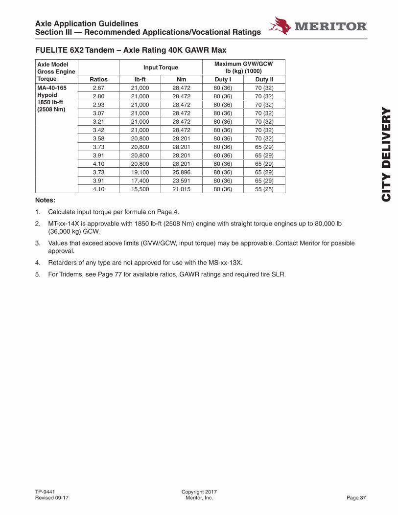
Axle Application GuidelinesSection III — Recommended Applications/Vocational Ratings
TP-9441 Copyright 2017Revised 09-17 Meritor, Inc. Page 37
FUELITE 6X2 Tandem – Axle Rating 40K GAWR Max
Axle Model Gross Engine Torque
Input TorqueMaximum GVW/GCW
lb (kg) (1000)Ratios lb-ft Nm Duty I Duty II
MA-40-165Hypoid1850 lb-ft(2508 Nm)
2.67 21,000 28,472 80 (36) 70 (32)2.80 21,000 28,472 80 (36) 70 (32)2.93 21,000 28,472 80 (36) 70 (32)3.07 21,000 28,472 80 (36) 70 (32)3.21 21,000 28,472 80 (36) 70 (32)3.42 21,000 28,472 80 (36) 70 (32)3.58 20,800 28,201 80 (36) 70 (32)3.73 20,800 28,201 80 (36) 65 (29)3.91 20,800 28,201 80 (36) 65 (29)4.10 20,800 28,201 80 (36) 65 (29)3.73 19,100 25,896 80 (36) 65 (29)3.91 17,400 23,591 80 (36) 65 (29)4.10 15,500 21,015 80 (36) 55 (25)
Notes:
1. Calculate input torque per formula on Page 4.
2. MT-xx-14X is approvable with 1850 lb-ft (2508 Nm) engine with straight torque engines up to 80,000 lb (36,000 kg) GCW.
3. Values that exceed above limits (GVW/GCW, input torque) may be approvable. Contact Meritor for possible approval.
4. Retarders of any type are not approved for use with the MS-xx-13X.
5. For Tridems, see Page 77 for available ratios, GAWR ratings and required tire SLR.
CIT
Y D
EL
IVE
RY
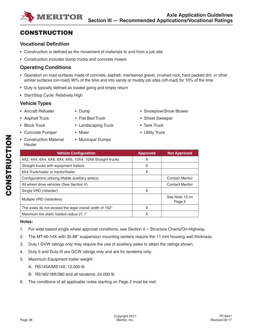
Axle Application GuidelinesSection III — Recommended Applications/Vocational Ratings
Copyright 2017 TP-9441Page 38 Meritor, Inc. Revised 09-17
CO
NS
TR
UC
TIO
N
CONSTRUCTION
Vocational Defi nition
• Construction is defi ned as the movement of materials to and from a job site
• Construction includes dump trucks and concrete mixers
Operating Conditions
• Operation on road surfaces made of concrete, asphalt, maintained gravel, crushed rock, hard packed dirt, or other similar surfaces (on-road) 90% of the time and into sandy or muddy job sites (off-road) for 10% of the time
• Duty is typically defi ned as loaded going and empty return
• Start/Stop Cycle: Relatively High
Vehicle Types
• Aircraft Refueler • Dump • Snowplow/Snow Blower
• Asphalt Truck • Flat Bed Truck • Street Sweeper
• Block Truck • Landscaping Truck • Tank Truck
• Concrete Pumper • Mixer • Utility Truck
• Construction Material • Municipal DumpsHauler
Vehicle Confi guration Approved Not Approved
4X2, 4X4, 6X4, 6X6, 8X4, 8X6, 10X4, 10X6 Straight trucks X
Straight trucks with equipment trailers X
6X4 Truck/trailer or tractor/trailer X
Confi gurations utilizing liftable auxiliary axle(s) Contact Meritor
All wheel drive vehicles (See Section V) Contact Meritor
Single VRD (retarder) X
Multiple VRD (retarders)See Note 15 on
Page 2
The axles do not exceed the legal overall width of 102” X
Maximum tire static loaded radius 21.1” X
Notes:
1. For wide based single wheel approval conditions, see Section II – Structure Charts/On-Highway.
2. The MT-40-14X with 35.88" suspension mounting centers require the 11 mm housing wall thickness.
3. Duty I GVW ratings only may require the use of auxiliary axles to attain the ratings shown.
4. Duty II and Duty III are GCW ratings only and are for tandems only.
5. Maximum Equipment trailer weight:
A. RS145A/MS14X: 12,000 lb
B. RS160/18X/380 and all tandems: 24,000 lb
6. The conditions of all applicable notes starting on Page 2 must be met.
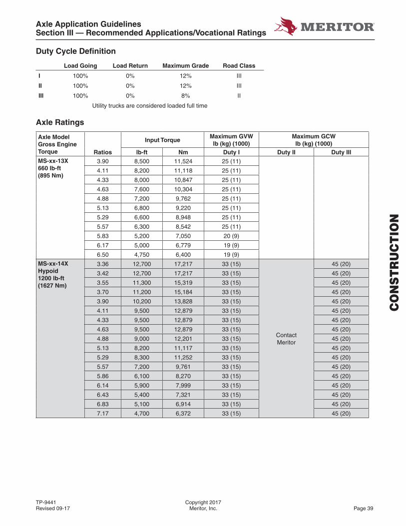
Axle Application GuidelinesSection III — Recommended Applications/Vocational Ratings
TP-9441 Copyright 2017Revised 09-17 Meritor, Inc. Page 39
CO
NS
TR
UC
TIO
N
Duty Cycle Defi nition
Load Going Load Return Maximum Grade Road Class
I 100% 0% 12% III
II 100% 0% 12% III
III 100% 0% 8% II
Utility trucks are considered loaded full time
Axle Ratings
Axle Model Gross Engine Torque
Input TorqueMaximum GVW lb (kg) (1000)
Maximum GCW lb (kg) (1000)
Ratios lb-ft Nm Duty I Duty II Duty IIIMS-xx-13X660 lb-ft(895 Nm)
3.90 8,500 11,524 25 (11)
4.11 8,200 11,118 25 (11)
4.33 8,000 10,847 25 (11)
4.63 7,600 10,304 25 (11)
4.88 7,200 9,762 25 (11)
5.13 6,800 9,220 25 (11)
5.29 6,600 8,948 25 (11)
5.57 6,300 8,542 25 (11)
5.83 5,200 7,050 20 (9)
6.17 5,000 6,779 19 (9)
6.50 4,750 6,400 19 (9)
MS-xx-14XHypoid1200 lb-ft(1627 Nm)
3.36 12,700 17,217 33 (15)
Contact Meritor
45 (20)
3.42 12,700 17,217 33 (15) 45 (20)
3.55 11,300 15,319 33 (15) 45 (20)
3.70 11,200 15,184 33 (15) 45 (20)
3.90 10,200 13,828 33 (15) 45 (20)
4.11 9,500 12,879 33 (15) 45 (20)
4.33 9,500 12,879 33 (15) 45 (20)
4.63 9,500 12,879 33 (15) 45 (20)
4.88 9,000 12,201 33 (15) 45 (20)
5.13 8,200 11,117 33 (15) 45 (20)
5.29 8,300 11,252 33 (15) 45 (20)
5.57 7,200 9,761 33 (15) 45 (20)
5.86 6,100 8,270 33 (15) 45 (20)
6.14 5,900 7,999 33 (15) 45 (20)
6.43 5,400 7,321 33 (15) 45 (20)
6.83 5,100 6,914 33 (15) 45 (20)
7.17 4,700 6,372 33 (15) 45 (20)
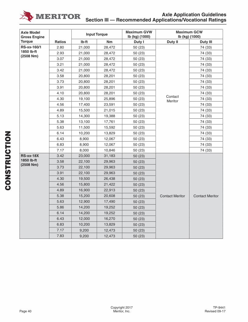
Axle Application GuidelinesSection III — Recommended Applications/Vocational Ratings
Copyright 2017 TP-9441Page 40 Meritor, Inc. Revised 09-17
Axle Model Gross Engine Torque
Input TorqueMaximum GVW lb (kg) (1000)
Maximum GCW lb (kg) (1000)
Ratios lb-ft Nm Duty I Duty II Duty IIIRS-xx-160/11850 lb-ft(2508 Nm)
2.80 21,000 28,472 50 (23)
Contact Meritor
74 (33)
2.93 21,000 28,472 50 (23) 74 (33)
3.07 21,000 28,472 50 (23) 74 (33)
3.21 21,000 28,472 50 (23) 74 (33)
3.42 21,000 28,472 50 (23) 74 (33)
3.58 20,800 28,201 50 (23) 74 (33)
3.73 20,800 28,201 50 (23) 74 (33)
3.91 20,800 28,201 50 (23) 74 (33)
4.10 20,800 28,201 50 (23) 74 (33)
4.30 19,100 25,896 50 (23) 74 (33)
4.56 17,400 23,591 50 (23) 74 (33)
4.89 15,500 21,015 50 (23) 74 (33)
5.13 14,300 19,388 50 (23) 74 (33)
5.38 13,100 17,761 50 (23) 74 (33)
5.63 11,500 15,592 50 (23) 74 (33)
6.14 10,200 13,829 50 (23) 74 (33)
6.43 8,900 12,067 50 (23) 74 (33)
6.83 8,900 12,067 50 (23) 74 (33)
7.17 8,000 10,846 50 (23) 74 (33)
RS-xx-18X1850 lb-ft(2508 Nm)
3.42 23,000 31,183 50 (23)
Contact Meritor Contact Meritor
3.58 22,100 29,963 50 (23)
3.73 22,100 29,963 50 (23)
3.91 22,100 29,963 50 (23)
4.30 19,500 26,438 50 (23)
4.56 15,800 21,422 50 (23)
4.89 16,900 22,913 50 (23)
5.38 15,200 20,608 50 (23)
5.63 12,900 17,490 50 (23)
5.86 14,200 19,252 50 (23)
6.14 14,200 19,252 50 (23)
6.43 12,000 16,270 50 (23)
6.83 10,200 13,829 50 (23)
7.17 9,200 12,473 50 (23)
7.83 9,200 12,473 50 (23)
CO
NS
TR
UC
TIO
N

Axle Application GuidelinesSection III — Recommended Applications/Vocational Ratings
TP-9441 Copyright 2017Revised 09-17 Meritor, Inc. Page 41
Axle Model Gross Engine Torque
Input TorqueMaximum GVW lb (kg) (1000)
Maximum GCW lb (kg) (1000)
Ratios lb-ft Nm Duty I Duty II Duty IIIRS-xx-3801850 lb-ft(2508 Nm)
5.52 13,600 18,439 50 (23)
Contact Meritor Contact Meritor
6.07 13,600 18,439 50 (23)
6.37 13,600 18,439 50 (23)
6.75 13,100 17,761 50 (23)
7.24 10,600 14,371 50 (23)
7.83 10,200 13,829 50 (23)
9.14 8,000 10,846 50 (23)
10.12 6,700 9,084 50 (23)
10.62 6,100 8,270 50 (23)
RT-xx-145AHypoid1650 lb-ft(2237 Nm)
3.25 23,000 31,181
68 (31)
80 (36) 110 (50)
3.36 23,000 31,181 80 (36) 110 (50)
3.42 23,000 31,181 80 (36) 110 (50)
3.55 22,100 29,961 80 (36) 110 (50)
3.70 22,100 29,961 80 (36) 110 (50)
3.90 22,100 29,961 80 (36) 110 (50)
4.11 22,100 29,961 80 (36) 110 (50)
4.33 21,800 29,554 80 (36) 110 (50)
4.63 20,400 27,656 80 (36) 105 (48)
4.88 18,000 24,403 80 (36) 105 (48)
5.29 16,600 22,505 80 (36) 100 (45)
5.86 12,200 16,540 70 (32) 80 (36)
6.14 11,800 15,997 70 (32) 70 (32)
6.43 10,800 13,964 70 (32) 70 (32)
6.83 10,200 13,828 70 (32) 70 (32)
7.17 9,400 12,744 70 (32) 70 (32)
MT-xx-14XHypoid/Amboid1650 lb-ft(2237 Nm)
3.25 23,000 31,181
68 (31)
80 (36) 110 (50)
3.36 23,000 31,181 80 (36) 110 (50)
3.42 23,000 31,181 80 (36) 110 (50)
3.55 22,100 29,961 80 (36) 110 (50)
3.70 22,100 29,961 80 (36) 110 (50)
3.90 22,100 29,961 80 (36) 110 (50)
4.11 22,100 29,961 80 (36) 110 (50)
4.33 21,800 29,554 80 (36) 110 (50)
4.63 20,400 27,656 80 (36) 105 (48)
4.88 18,000 24,403 80 (36) 105 (48)
5.29 16,600 22,505 80 (36) 100 (45)
5.86 12,200 16,540 70 (32) 80 (36)
6.14 11,800 15,997 70 (32) 70 (32)
6.43 10,900 13,964 70 (32) 70 (32)
6.83 10,300 13,828 70 (32) 70 (32)
7.17 9,500 12,744 70 (32) 70 (32)
CO
NS
TR
UC
TIO
N

Axle Application GuidelinesSection III — Recommended Applications/Vocational Ratings
Copyright 2017 TP-9441Page 42 Meritor, Inc. Revised 09-17
CO
NS
TR
UC
TIO
N
Axle Model Gross Engine Torque
Input TorqueMaximum GVW lb (kg) (1000)
Maximum GCW lb (kg) (1000)
Ratios lb-ft Nm Duty I Duty II Duty IIIRT-xx-16X2050 lb-ft(2779 Nm)
RZ-166 Tridem2050 lb-ft(2779 Nm)See Note 3.
3.07 30,000 40,674 100 (45) 145 (66) 164 (74)
3.21 30,000 40,674 100 (45) 145 (66) 164 (74)
3.42 30,000 40,674 100 (45) 145 (66) 164 (74)
3.58 30,000 40,674 100 (45) 145 (66) 164 (74)
3.73 30,000 40,674 100 (45) 145 (66) 164 (74)
3.91 30,000 40,674 100 (45) 145 (66) 164 (74)
4.10 30,000 40,674 100 (45) 145 (66) 164 (74)
4.30 30,000 40,674 100 (45) 145 (66) 160 (73)
4.56 30,000 40,674 100 (45) 145 (66) 160 (73)
4.89 30,000 40,674 100 (45) 130 (59) 150 (68)
5.38 26,000 35,522 100 (45) 130 (59) 140 (63.5)
5.63 23,000 31,181 100 (45) 130 (59) 140 (63.5)
6.14 20,400 27,656 100 (45) 130 (59) 120 (54.5)
6.43 17,800 24,133 100 (45) 130 (59) 110 (50)
6.83 17,800 24,133 100 (45) 130 (59) 100 (45)
7.17 16,000 21,693 100 (45) 130 (59) 90 (36)
RT-xx-1852050 lb-ft(2779 Nm)
RZ-188 Tridem2050 lb-ft(2779 Nm)See Note 3.
3.73 30,000 40,674 100 (45) 170 (77) 185 (84)
4.30 30,000 40,674 100 (45) 170 (77) 185 (84)
4.56 30,000 40,674 100 (45) 170 (77) 180 (81.5)
4.89 30,000 40,674 100 (45) 155 (70) 180 (81.5)
5.38 30,000 40,674 100 (45) 155 (70) 160 (73)
6.14 24,000 32,539 100 (45) 155 (70) 154 (70)
6.83 20,400 27,656 100 (45) 155 (70) 130 (59)
7.17 18,000 24,947 100 (45) 155 (70) 120 (54.5)
RT-xx-3802050 lb-ft(2779 Nm)
5.52 30,000 40,674 100 (45) 185 (84) 170 (77)
6.07 30,000 40,674 100 (45) 185 (84) 170 (77)
6.37 27,200 36,878 100 (45) 185 (84) 170 (77)
6.75 26,200 35,522 100 (45) 170 (77) 160 (70)
7.24 21,200 28,743 100 (45) 170 (77) 150 (68)
7.83 20,400 27,656 100 (45) 170 (77) 140 (63.5)
9.14 16,000 21,693 100 (45) 170 (77) 130 (59)
10.12 13,400 18,168 100 (45) 140 (63.5) 110 (50)
10.62 12,200 16,540 100 (45) 130 (59) 100 (45)
Notes:
1. Calculate input torque per formula on Page 4.
2. Values that exceed above limits (GVW/GCW, input torque) may be approvable. Contact Meritor for possible approval.
3. For Tridems, see Page 77 for available ratios, GAWR ratings and required tire SLR.
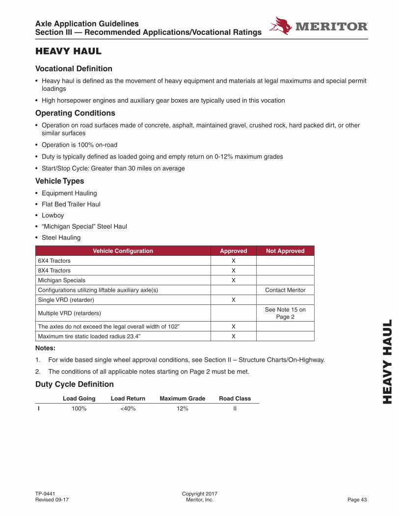
Axle Application GuidelinesSection III — Recommended Applications/Vocational Ratings
TP-9441 Copyright 2017Revised 09-17 Meritor, Inc. Page 43
HEAVY HAUL
Vocational Defi nition
• Heavy haul is defi ned as the movement of heavy equipment and materials at legal maximums and special permit loadings
• High horsepower engines and auxiliary gear boxes are typically used in this vocation
Operating Conditions
• Operation on road surfaces made of concrete, asphalt, maintained gravel, crushed rock, hard packed dirt, or other similar surfaces
• Operation is 100% on-road
• Duty is typically defi ned as loaded going and empty return on 0-12% maximum grades
• Start/Stop Cycle: Greater than 30 miles on average
Vehicle Types
• Equipment Hauling
• Flat Bed Trailer Haul
• Lowboy
• “Michigan Special” Steel Haul
• Steel Hauling
Vehicle Confi guration Approved Not Approved
6X4 Tractors X
8X4 Tractors X
Michigan Specials X
Confi gurations utilizing liftable auxiliary axle(s) Contact Meritor
Single VRD (retarder) X
Multiple VRD (retarders)See Note 15 on
Page 2
The axles do not exceed the legal overall width of 102” X
Maximum tire static loaded radius 23.4” X
Notes:
1. For wide based single wheel approval conditions, see Section II – Structure Charts/On-Highway.
2. The conditions of all applicable notes starting on Page 2 must be met.
Duty Cycle Defi nition
Load Going Load Return Maximum Grade Road Class
I 100% <40% 12% II
HE
AV
Y H
AU
L
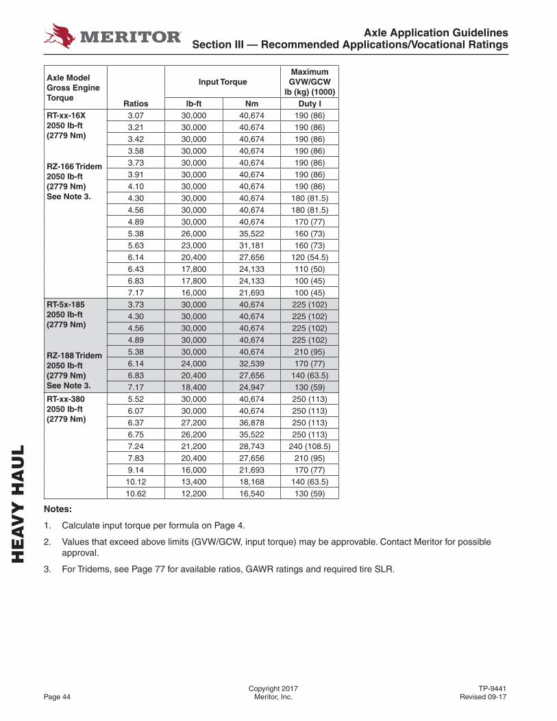
Axle Application GuidelinesSection III — Recommended Applications/Vocational Ratings
Copyright 2017 TP-9441Page 44 Meritor, Inc. Revised 09-17
HE
AV
Y H
AU
L
Axle Model Gross Engine Torque
Input TorqueMaximum GVW/GCW
lb (kg) (1000)Ratios lb-ft Nm Duty I
RT-xx-16X2050 lb-ft(2779 Nm)
RZ-166 Tridem2050 lb-ft(2779 Nm)See Note 3.
3.07 30,000 40,674 190 (86)3.21 30,000 40,674 190 (86)3.42 30,000 40,674 190 (86)3.58 30,000 40,674 190 (86)3.73 30,000 40,674 190 (86)3.91 30,000 40,674 190 (86)4.10 30,000 40,674 190 (86)4.30 30,000 40,674 180 (81.5)4.56 30,000 40,674 180 (81.5)4.89 30,000 40,674 170 (77)5.38 26,000 35,522 160 (73)5.63 23,000 31,181 160 (73)6.14 20,400 27,656 120 (54.5)6.43 17,800 24,133 110 (50)6.83 17,800 24,133 100 (45)7.17 16,000 21,693 100 (45)
RT-5x-1852050 lb-ft(2779 Nm)
RZ-188 Tridem2050 lb-ft(2779 Nm)See Note 3.
3.73 30,000 40,674 225 (102)4.30 30,000 40,674 225 (102)4.56 30,000 40,674 225 (102)4.89 30,000 40,674 225 (102)5.38 30,000 40,674 210 (95)6.14 24,000 32,539 170 (77)6.83 20,400 27,656 140 (63.5)7.17 18,400 24,947 130 (59)
RT-xx-3802050 lb-ft(2779 Nm)
5.52 30,000 40,674 250 (113)6.07 30,000 40,674 250 (113)6.37 27,200 36,878 250 (113)6.75 26,200 35,522 250 (113)7.24 21,200 28,743 240 (108.5)7.83 20,400 27,656 210 (95)9.14 16,000 21,693 170 (77)10.12 13,400 18,168 140 (63.5)10.62 12,200 16,540 130 (59)
Notes:
1. Calculate input torque per formula on Page 4.
2. Values that exceed above limits (GVW/GCW, input torque) may be approvable. Contact Meritor for possible approval.
3. For Tridems, see Page 77 for available ratios, GAWR ratings and required tire SLR.
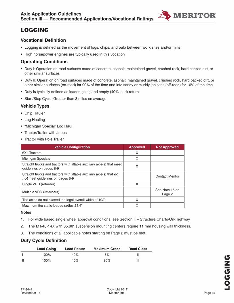
Axle Application GuidelinesSection III — Recommended Applications/Vocational Ratings
TP-9441 Copyright 2017Revised 09-17 Meritor, Inc. Page 45
LOGGING
Vocational Defi nition
• Logging is defi ned as the movement of logs, chips, and pulp between work sites and/or mills
• High horsepower engines are typically used in this vocation
Operating Conditions
• Duty I: Operation on road surfaces made of concrete, asphalt, maintained gravel, crushed rock, hard packed dirt, or other similar surfaces
• Duty II: Operation on road surfaces made of concrete, asphalt, maintained gravel, crushed rock, hard packed dirt, or other similar surfaces (on-road) for 90% of the time and into sandy or muddy job sites (off-road) for 10% of the time
• Duty is typically defi ned as loaded going and empty (40% load) return
• Start/Stop Cycle: Greater than 3 miles on average
Vehicle Types
• Chip Hauler
• Log Hauling
• “Michigan Special” Log Haul
• Tractor/Trailer with Jeeps
• Tractor with Pole Trailer
Vehicle Confi guration Approved Not Approved
6X4 Tractors X
Michigan Specials X
Straight trucks and tractors with liftable auxiliary axle(s) that meet guidelines on pages 8-9
X
Straight trucks and tractors with liftable auxiliary axle(s) that do not meet guidelines on pages 8-9
Contact Meritor
Single VRD (retarder) X
Multiple VRD (retarders)See Note 15 on
Page 2
The axles do not exceed the legal overall width of 102” X
Maximum tire static loaded radius 23.4” X
Notes:
1. For wide based single wheel approval conditions, see Section II – Structure Charts/On-Highway.
2. The MT-40-14X with 35.88" suspension mounting centers require 11 mm housing wall thickness.
3. The conditions of all applicable notes starting on Page 2 must be met.
Duty Cycle Defi nition
Load Going Load Return Maximum Grade Road Class
I 100% 40% 8% II
II 100% 40% 20% III
LO
GG
ING
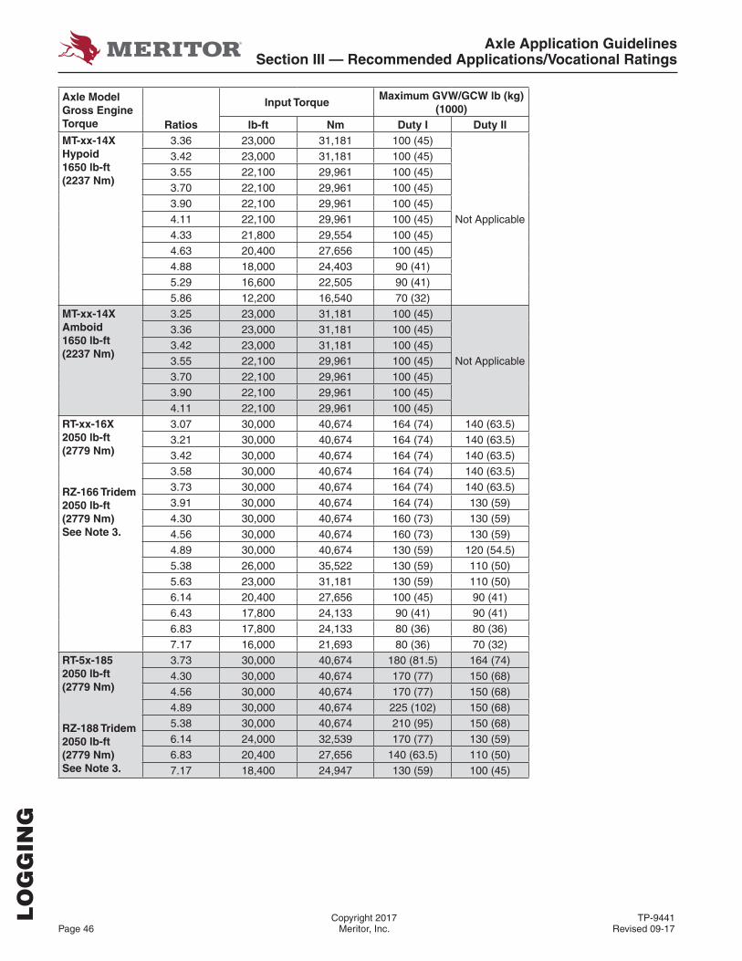
Axle Application GuidelinesSection III — Recommended Applications/Vocational Ratings
Copyright 2017 TP-9441Page 46 Meritor, Inc. Revised 09-17
Axle Model Gross Engine Torque
Input TorqueMaximum GVW/GCW lb (kg)
(1000)Ratios lb-ft Nm Duty I Duty II
MT-xx-14XHypoid1650 lb-ft(2237 Nm)
3.36 23,000 31,181 100 (45)
Not Applicable
3.42 23,000 31,181 100 (45)3.55 22,100 29,961 100 (45)3.70 22,100 29,961 100 (45)3.90 22,100 29,961 100 (45)4.11 22,100 29,961 100 (45)4.33 21,800 29,554 100 (45)4.63 20,400 27,656 100 (45)4.88 18,000 24,403 90 (41)5.29 16,600 22,505 90 (41)5.86 12,200 16,540 70 (32)
MT-xx-14XAmboid1650 lb-ft(2237 Nm)
3.25 23,000 31,181 100 (45)
Not Applicable
3.36 23,000 31,181 100 (45)3.42 23,000 31,181 100 (45)3.55 22,100 29,961 100 (45)3.70 22,100 29,961 100 (45)3.90 22,100 29,961 100 (45)4.11 22,100 29,961 100 (45)
RT-xx-16X2050 lb-ft(2779 Nm)
RZ-166 Tridem2050 lb-ft(2779 Nm)See Note 3.
3.07 30,000 40,674 164 (74) 140 (63.5)3.21 30,000 40,674 164 (74) 140 (63.5)3.42 30,000 40,674 164 (74) 140 (63.5)3.58 30,000 40,674 164 (74) 140 (63.5)3.73 30,000 40,674 164 (74) 140 (63.5)3.91 30,000 40,674 164 (74) 130 (59)4.30 30,000 40,674 160 (73) 130 (59)4.56 30,000 40,674 160 (73) 130 (59)4.89 30,000 40,674 130 (59) 120 (54.5)5.38 26,000 35,522 130 (59) 110 (50)5.63 23,000 31,181 130 (59) 110 (50)6.14 20,400 27,656 100 (45) 90 (41)6.43 17,800 24,133 90 (41) 90 (41)6.83 17,800 24,133 80 (36) 80 (36)7.17 16,000 21,693 80 (36) 70 (32)
RT-5x-1852050 lb-ft(2779 Nm)
RZ-188 Tridem2050 lb-ft(2779 Nm)See Note 3.
3.73 30,000 40,674 180 (81.5) 164 (74)4.30 30,000 40,674 170 (77) 150 (68)4.56 30,000 40,674 170 (77) 150 (68)4.89 30,000 40,674 225 (102) 150 (68)5.38 30,000 40,674 210 (95) 150 (68)6.14 24,000 32,539 170 (77) 130 (59)6.83 20,400 27,656 140 (63.5) 110 (50)7.17 18,400 24,947 130 (59) 100 (45)
LO
GG
ING
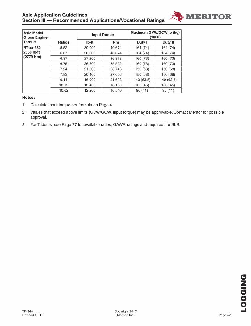
Axle Application GuidelinesSection III — Recommended Applications/Vocational Ratings
TP-9441 Copyright 2017Revised 09-17 Meritor, Inc. Page 47
Axle Model Gross Engine Torque
Input TorqueMaximum GVW/GCW lb (kg)
(1000)Ratios lb-ft Nm Duty I Duty II
RT-xx-3802050 lb-ft(2779 Nm)
5.52 30,000 40,674 164 (74) 164 (74)6.07 30,000 40,674 164 (74) 164 (74)6.37 27,200 36,878 160 (73) 160 (73)6.75 26,200 35,522 160 (73) 160 (73)7.24 21,200 28,743 150 (68) 150 (68)7.83 20,400 27,656 150 (68) 150 (68)9.14 16,000 21,693 140 (63.5) 140 (63.5)10.12 13,400 18,168 100 (45) 100 (45)10.62 12,200 16,540 90 (41) 90 (41)
Notes:
1. Calculate input torque per formula on Page 4.
2. Values that exceed above limits (GVW/GCW, input torque) may be approvable. Contact Meritor for possible approval.
3. For Tridems, see Page 77 for available ratios, GAWR ratings and required tire SLR.
LO
GG
ING

Axle Application GuidelinesSection III — Recommended Applications/Vocational Ratings
Copyright 2017 TP-9441Page 48 Meritor, Inc. Revised 09-17
MINING
Vocational Defi nition
• Mining is defi ned as the movement of rock, ore, gravel, and minerals between mining sites, processing, and delivery sites
• Tractor/Trailer construction vehicles are also included in this vocation
• High horsepower engines are typically used in this vocation
Operating Conditions
• Variety of terrain conditions: light grade (0-8%), moderate grade (0-12%), severe grade (0-20%)
• Operation on road surfaces made of concrete, asphalt, maintained gravel, crushed rock, hard packed dirt, or other similar surfaces (on-road) for 95% of the time and off-road for 5% of the time
• Duty is typically defi ned as loaded going and empty return
• Start/Stop Cycle: 3-30 miles
Vehicle Types
• Bottom Dump Trailer Combination
• Hopper Trailer Combinations
• “Michigan Special” Gravel Trains
• Semi-End Dump
• Transfer Dump
Vehicle Confi guration Approved Not Approved
6X4, 8X4, 10X4 tractors and trucks with full trailers X
Michigan Specials X
Straight trucks and tractors with liftable auxiliary axle(s) that meet guidelines on pages 8-9
X
Straight trucks and tractors with liftable auxiliary axle(s) that do not meet guidelines on pages 8-9
Contact Meritor
Downgrades greater than 40% of loaded distance may require de-rating
Single VRD (retarder) X
Multiple VRD (retarders)See Note 15 on
Page 2
The axles do not exceed the legal overall width of 102” X
Maximum tire static loaded radius 23.4” X
Notes:
1. For wide based single wheel approval conditions, see Section II – Structure Charts/On-Highway.
2. The MT-40-14X with 35.88" suspension mounting centers require 11 mm housing wall thickness.
3. The conditions of all applicable notes starting on Page 2 must be met.
MIN
ING
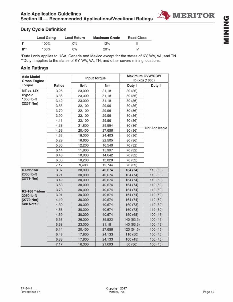
Axle Application GuidelinesSection III — Recommended Applications/Vocational Ratings
TP-9441 Copyright 2017Revised 09-17 Meritor, Inc. Page 49
MIN
ING
Duty Cycle Defi nition
Load Going Load Return Maximum Grade Road Class
I* 100% 0% 12% II
II** 100% 0% 20% IV
*Duty I only applies to USA, Canada and Mexico except for the states of KY, WV, VA, and TN.**Duty II applies to the states of KY, WV, VA, TN, and other severe mining locations.
Axle Ratings
Axle Model Gross Engine Torque
Input TorqueMaximum GVW/GCW
lb (kg) (1000)
Ratios lb-ft Nm Duty I Duty II
MT-xx-14XHypoid1650 lb-ft(2237 Nm)
3.25 23,000 31,181 80 (36)
Not Applicable
3.36 23,000 31,181 80 (36)3.42 23,000 31,181 80 (36)3.55 22,100 29,961 80 (36)3.70 22,100 29,961 80 (36)3.90 22,100 29,961 80 (36)4.11 22,100 29,961 80 (36)4.33 21,800 29,554 80 (36)4.63 20,400 27,656 80 (36)4.88 18,000 24,403 80 (36)5.29 16,600 22,505 80 (36)5.86 12,200 16,540 70 (32)6.14 11,800 15,997 70 (32)6.43 10,800 14,642 70 (32)6.83 10,200 13,828 70 (32)7.17 9,400 12,744 70 (32)
RT-xx-16X2050 lb-ft(2779 Nm)
RZ-166 Tridem2050 lb-ft(2779 Nm)See Note 3.
3.07 30,000 40,674 164 (74) 110 (50)3.21 30,000 40,674 164 (74) 110 (50)3.42 30,000 40,674 164 (74) 110 (50)3.58 30,000 40,674 164 (74) 110 (50)3.73 30,000 40,674 164 (74) 110 (50)3.91 30,000 40,674 164 (74) 110 (50)4.10 30,000 40,674 164 (74) 110 (50)4.30 30,000 40,674 160 (73) 110 (50)4.56 30,000 40,674 160 (73) 110 (50)4.89 30,000 40,674 150 (68) 100 (45)5.38 26,000 35,522 140 (63.5) 100 (45)5.63 23,000 31,181 140 (63.5) 100 (45)6.14 20,400 27,656 120 (54.5) 100 (45)6.43 17,800 24,133 110 (50) 100 (45)6.83 17,800 24,133 100 (45) 100 (45)7.17 16,000 21,693 80 (36) 100 (45)
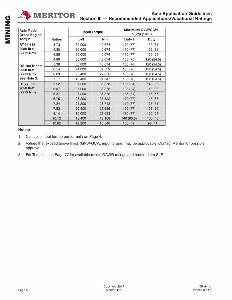
Axle Application GuidelinesSection III — Recommended Applications/Vocational Ratings
Copyright 2017 TP-9441Page 50 Meritor, Inc. Revised 09-17
MIN
ING
Axle Model Gross Engine Torque
Input TorqueMaximum GVW/GCW
lb (kg) (1000)
Ratios lb-ft Nm Duty I Duty II
RT-5x-1852050 lb-ft(2779 Nm)
RZ-188 Tridem2050 lb-ft(2779 Nm)See Note 3.
3.73 30,000 40,674 170 (77) 135 (61)4.30 30,000 40,674 170 (77) 135 (61)4.56 30,000 40,674 170 (77) 135 (61)4.89 30,000 40,674 155 (70) 120 (54.5)5.38 30,000 40,674 155 (70) 120 (54.5)6.14 24,000 32,539 155 (70) 120 (54.5)6.83 20,400 27,656 155 (70) 120 (54.5)7.17 18,400 24,947 155 (70) 120 (54.5)
RT-xx-3802050 lb-ft(2779 Nm)
5.52 27,200 36,878 185 (84) 145 (66)6.07 27,200 36,878 185 (84) 145 (66)6.37 27,200 36,878 185 (84) 145 (66)6.75 26,200 35,522 170 (77) 145 (66)7.24 21,200 28,743 170 (77) 135 (61)7.83 20,400 27,656 170 (77) 135 (61)9.14 16,000 21,693 170 (77) 135 (61)10.12 13,400 18,168 140 (63.5) 100 (45)10.62 12,200 16,540 130 (59) 90 (41)
Notes:
1. Calculate input torque per formula on Page 4.
2. Values that exceed above limits (GVW/GCW, input torque) may be approvable. Contact Meritor for possible approval.
3. For Tridems, see Page 77 for available ratios, GAWR ratings and required tire SLR.
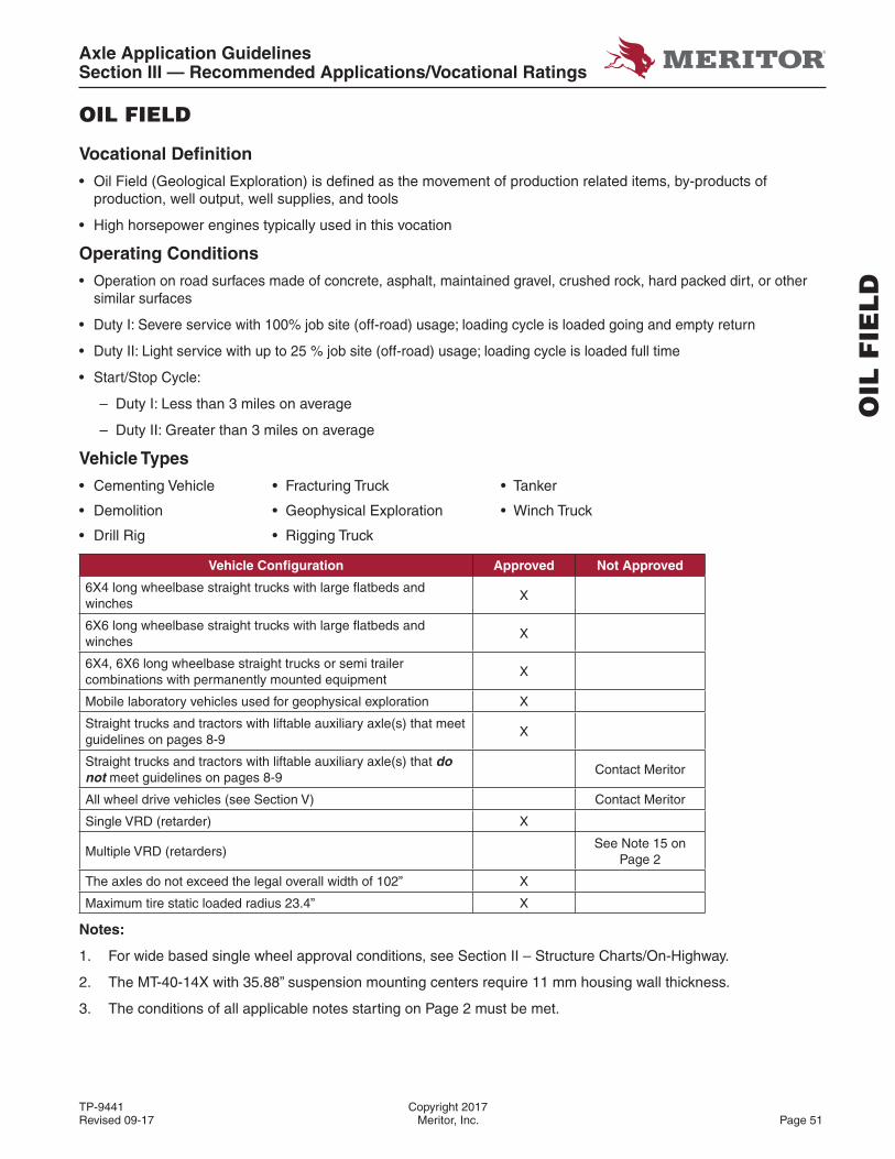
Axle Application GuidelinesSection III — Recommended Applications/Vocational Ratings
TP-9441 Copyright 2017Revised 09-17 Meritor, Inc. Page 51
OIL
FIE
LD
OIL FIELD
Vocational Defi nition
• Oil Field (Geological Exploration) is defi ned as the movement of production related items, by-products of production, well output, well supplies, and tools
• High horsepower engines typically used in this vocation
Operating Conditions
• Operation on road surfaces made of concrete, asphalt, maintained gravel, crushed rock, hard packed dirt, or other similar surfaces
• Duty I: Severe service with 100% job site (off-road) usage; loading cycle is loaded going and empty return
• Duty II: Light service with up to 25 % job site (off-road) usage; loading cycle is loaded full time
• Start/Stop Cycle:
– Duty I: Less than 3 miles on average
– Duty II: Greater than 3 miles on average
Vehicle Types
• Cementing Vehicle • Fracturing Truck • Tanker
• Demolition • Geophysical Exploration • Winch Truck
• Drill Rig • Rigging Truck
Vehicle Confi guration Approved Not Approved
6X4 long wheelbase straight trucks with large fl atbeds and winches
X
6X6 long wheelbase straight trucks with large fl atbeds and winches
X
6X4, 6X6 long wheelbase straight trucks or semi trailer combinations with permanently mounted equipment
X
Mobile laboratory vehicles used for geophysical exploration X
Straight trucks and tractors with liftable auxiliary axle(s) that meet guidelines on pages 8-9
X
Straight trucks and tractors with liftable auxiliary axle(s) that do not meet guidelines on pages 8-9
Contact Meritor
All wheel drive vehicles (see Section V) Contact Meritor
Single VRD (retarder) X
Multiple VRD (retarders)See Note 15 on
Page 2
The axles do not exceed the legal overall width of 102” X
Maximum tire static loaded radius 23.4” X
Notes:
1. For wide based single wheel approval conditions, see Section II – Structure Charts/On-Highway.
2. The MT-40-14X with 35.88” suspension mounting centers require 11 mm housing wall thickness.
3. The conditions of all applicable notes starting on Page 2 must be met.
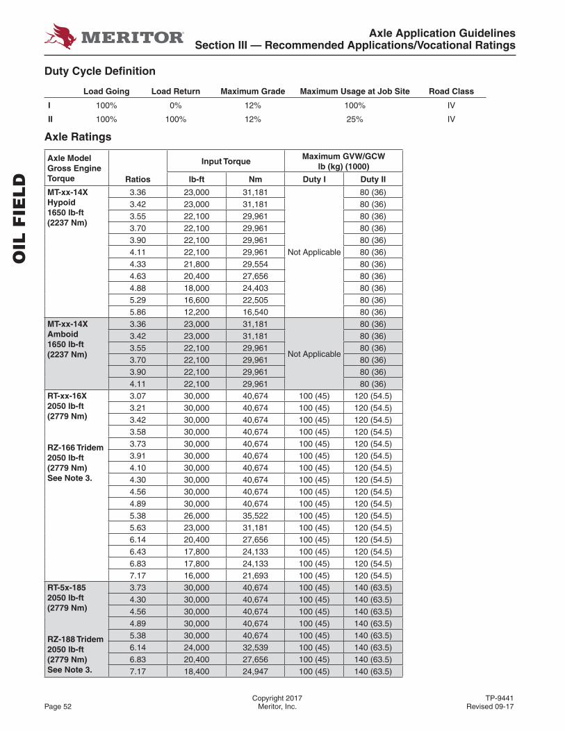
Axle Application GuidelinesSection III — Recommended Applications/Vocational Ratings
Copyright 2017 TP-9441Page 52 Meritor, Inc. Revised 09-17
Duty Cycle Defi nition
Load Going Load Return Maximum Grade Maximum Usage at Job Site Road Class
I 100% 0% 12% 100% IV
II 100% 100% 12% 25% IV
Axle Ratings
Axle Model Gross Engine Torque
Input TorqueMaximum GVW/GCW
lb (kg) (1000)
Ratios lb-ft Nm Duty I Duty II
MT-xx-14XHypoid1650 lb-ft(2237 Nm)
3.36 23,000 31,181
Not Applicable
80 (36)3.42 23,000 31,181 80 (36)3.55 22,100 29,961 80 (36)3.70 22,100 29,961 80 (36)3.90 22,100 29,961 80 (36)4.11 22,100 29,961 80 (36)4.33 21,800 29,554 80 (36)4.63 20,400 27,656 80 (36)4.88 18,000 24,403 80 (36)5.29 16,600 22,505 80 (36)5.86 12,200 16,540 80 (36)
MT-xx-14XAmboid1650 lb-ft(2237 Nm)
3.36 23,000 31,181
Not Applicable
80 (36)3.42 23,000 31,181 80 (36)3.55 22,100 29,961 80 (36)3.70 22,100 29,961 80 (36)3.90 22,100 29,961 80 (36)4.11 22,100 29,961 80 (36)
RT-xx-16X2050 lb-ft(2779 Nm)
RZ-166 Tridem2050 lb-ft(2779 Nm)See Note 3.
3.07 30,000 40,674 100 (45) 120 (54.5)3.21 30,000 40,674 100 (45) 120 (54.5)3.42 30,000 40,674 100 (45) 120 (54.5)3.58 30,000 40,674 100 (45) 120 (54.5)3.73 30,000 40,674 100 (45) 120 (54.5)3.91 30,000 40,674 100 (45) 120 (54.5)4.10 30,000 40,674 100 (45) 120 (54.5)4.30 30,000 40,674 100 (45) 120 (54.5)4.56 30,000 40,674 100 (45) 120 (54.5)4.89 30,000 40,674 100 (45) 120 (54.5)5.38 26,000 35,522 100 (45) 120 (54.5)5.63 23,000 31,181 100 (45) 120 (54.5)6.14 20,400 27,656 100 (45) 120 (54.5)6.43 17,800 24,133 100 (45) 120 (54.5)6.83 17,800 24,133 100 (45) 120 (54.5)7.17 16,000 21,693 100 (45) 120 (54.5)
RT-5x-1852050 lb-ft(2779 Nm)
RZ-188 Tridem2050 lb-ft(2779 Nm)See Note 3.
3.73 30,000 40,674 100 (45) 140 (63.5)4.30 30,000 40,674 100 (45) 140 (63.5)4.56 30,000 40,674 100 (45) 140 (63.5)4.89 30,000 40,674 100 (45) 140 (63.5)5.38 30,000 40,674 100 (45) 140 (63.5)6.14 24,000 32,539 100 (45) 140 (63.5)6.83 20,400 27,656 100 (45) 140 (63.5)7.17 18,400 24,947 100 (45) 140 (63.5)
OIL
FIE
LD
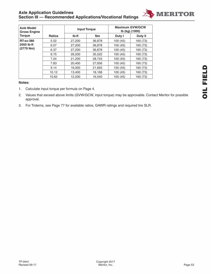
Axle Application GuidelinesSection III — Recommended Applications/Vocational Ratings
TP-9441 Copyright 2017Revised 09-17 Meritor, Inc. Page 53
Axle Model Gross Engine Torque
Input TorqueMaximum GVW/GCW
lb (kg) (1000)
Ratios lb-ft Nm Duty I Duty II
RT-xx-3802050 lb-ft(2779 Nm)
5.52 27,200 36,878 100 (45) 160 (73)6.07 27,200 36,878 100 (45) 160 (73)6.37 27,200 36,878 100 (45) 160 (73)6.75 26,200 35,522 100 (45) 160 (73)7.24 21,200 28,743 100 (45) 160 (73)7.83 20,400 27,656 100 (45) 160 (73)9.14 16,000 21,693 100 (45) 160 (73)10.12 13,400 18,168 100 (45) 160 (73)10.62 12,200 16,540 100 (45) 160 (73)
Notes:
1. Calculate input torque per formula on Page 4.
2. Values that exceed above limits (GVW/GCW, input torque) may be approvable. Contact Meritor for possible approval.
3. For Tridems, see Page 77 for available ratios, GAWR ratings and required tire SLR.
OIL
FIE
LD
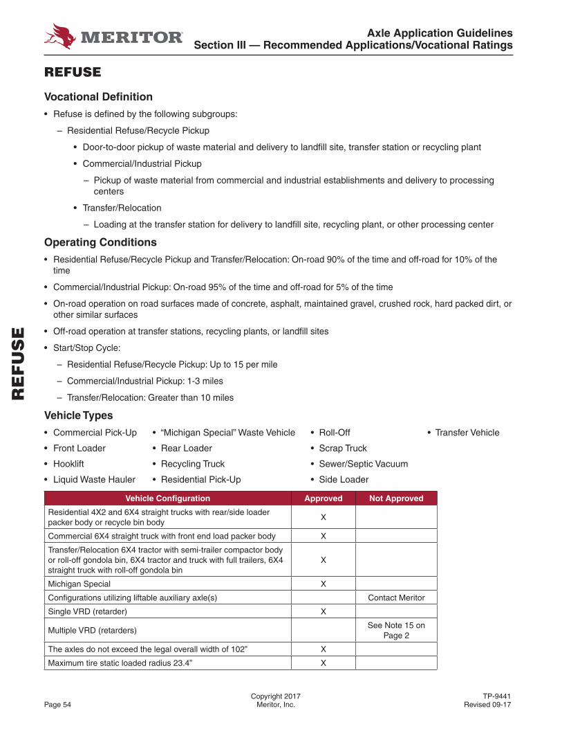
Axle Application GuidelinesSection III — Recommended Applications/Vocational Ratings
Copyright 2017 TP-9441Page 54 Meritor, Inc. Revised 09-17
REFUSE
Vocational Defi nition
• Refuse is defi ned by the following subgroups:
– Residential Refuse/Recycle Pickup
• Door-to-door pickup of waste material and delivery to landfi ll site, transfer station or recycling plant
• Commercial/Industrial Pickup
– Pickup of waste material from commercial and industrial establishments and delivery to processing centers
• Transfer/Relocation
– Loading at the transfer station for delivery to landfi ll site, recycling plant, or other processing center
Operating Conditions
• Residential Refuse/Recycle Pickup and Transfer/Relocation: On-road 90% of the time and off-road for 10% of the time
• Commercial/Industrial Pickup: On-road 95% of the time and off-road for 5% of the time
• On-road operation on road surfaces made of concrete, asphalt, maintained gravel, crushed rock, hard packed dirt, or other similar surfaces
• Off-road operation at transfer stations, recycling plants, or landfi ll sites
• Start/Stop Cycle:
– Residential Refuse/Recycle Pickup: Up to 15 per mile
– Commercial/Industrial Pickup: 1-3 miles
– Transfer/Relocation: Greater than 10 miles
Vehicle Types
• Commercial Pick-Up • “Michigan Special” Waste Vehicle • Roll-Off • Transfer Vehicle
• Front Loader • Rear Loader • Scrap Truck
• Hooklift • Recycling Truck • Sewer/Septic Vacuum
• Liquid Waste Hauler • Residential Pick-Up • Side Loader
Vehicle Confi guration Approved Not Approved
Residential 4X2 and 6X4 straight trucks with rear/side loader packer body or recycle bin body
X
Commercial 6X4 straight truck with front end load packer body X
Transfer/Relocation 6X4 tractor with semi-trailer compactor body or roll-off gondola bin, 6X4 tractor and truck with full trailers, 6X4 straight truck with roll-off gondola bin
X
Michigan Special X
Confi gurations utilizing liftable auxiliary axle(s) Contact Meritor
Single VRD (retarder) X
Multiple VRD (retarders)See Note 15 on
Page 2
The axles do not exceed the legal overall width of 102” X
Maximum tire static loaded radius 23.4” X
RE
FU
SE
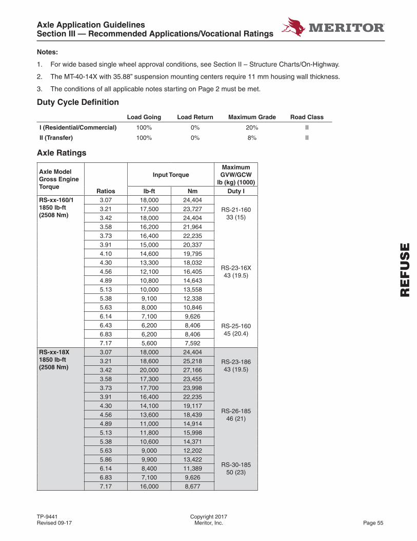
Axle Application GuidelinesSection III — Recommended Applications/Vocational Ratings
TP-9441 Copyright 2017Revised 09-17 Meritor, Inc. Page 55
Notes:
1. For wide based single wheel approval conditions, see Section II – Structure Charts/On-Highway.
2. The MT-40-14X with 35.88” suspension mounting centers require 11 mm housing wall thickness.
3. The conditions of all applicable notes starting on Page 2 must be met.
Duty Cycle Defi nition
Load Going Load Return Maximum Grade Road Class
I (Residential/Commercial) 100% 0% 20% II
II (Transfer) 100% 0% 8% II
Axle Ratings
Axle Model Gross Engine Torque
Input TorqueMaximum GVW/GCW
lb (kg) (1000)Ratios lb-ft Nm Duty I
RS-xx-160/11850 lb-ft(2508 Nm)
3.07 18,000 24,404
RS-21-16033 (15)
3.21 17,500 23,727
3.42 18,000 24,404
3.58 16,200 21,964
3.73 16,400 22,235
RS-23-16X43 (19.5)
3.91 15,000 20,337
4.10 14,600 19,795
4.30 13,300 18,032
4.56 12,100 16,405
4.89 10,800 14,643
5.13 10,000 13,558
5.38 9,100 12,338
5.63 8,000 10,846
6.14 7,100 9,626
RS-25-16045 (20.4)
6.43 6,200 8,406
6.83 6,200 8,406
7.17 5,600 7,592
RS-xx-18X1850 lb-ft(2508 Nm)
3.07 18,000 24,404
RS-23-18643 (19.5)
3.21 18,600 25,218
3.42 20,000 27,166
3.58 17,300 23,455
3.73 17,700 23,998
RS-26-18546 (21)
3.91 16,400 22,235
4.30 14,100 19,117
4.56 13,600 18,439
4.89 11,000 14,914
5.13 11,800 15,998
5.38 10,600 14,371
5.63 9,000 12,202
RS-30-18550 (23)
5.86 9,900 13,422
6.14 8,400 11,389
6.83 7,100 9,626
7.17 16,000 8,677
RE
FU
SE
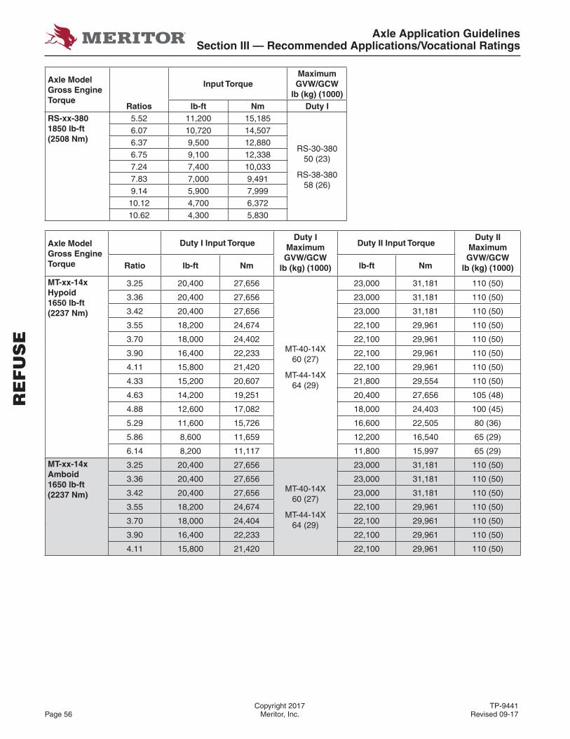
Axle Application GuidelinesSection III — Recommended Applications/Vocational Ratings
Copyright 2017 TP-9441Page 56 Meritor, Inc. Revised 09-17
Axle Model Gross Engine Torque
Input TorqueMaximum GVW/GCW
lb (kg) (1000)Ratios lb-ft Nm Duty I
RS-xx-3801850 lb-ft(2508 Nm)
5.52 11,200 15,185
RS-30-38050 (23)
RS-38-38058 (26)
6.07 10,720 14,5076.37 9,500 12,8806.75 9,100 12,3387.24 7,400 10,0337.83 7,000 9,4919.14 5,900 7,99910.12 4,700 6,37210.62 4,300 5,830
Axle Model Gross Engine Torque
Duty I Input TorqueDuty I
Maximum GVW/GCW
lb (kg) (1000)
Duty II Input TorqueDuty II
Maximum GVW/GCW
lb (kg) (1000)Ratio lb-ft Nm lb-ft Nm
MT-xx-14xHypoid1650 lb-ft(2237 Nm)
3.25 20,400 27,656
MT-40-14X60 (27)
MT-44-14X64 (29)
23,000 31,181 110 (50)
3.36 20,400 27,656 23,000 31,181 110 (50)
3.42 20,400 27,656 23,000 31,181 110 (50)
3.55 18,200 24,674 22,100 29,961 110 (50)
3.70 18,000 24,402 22,100 29,961 110 (50)
3.90 16,400 22,233 22,100 29,961 110 (50)
4.11 15,800 21,420 22,100 29,961 110 (50)
4.33 15,200 20,607 21,800 29,554 110 (50)
4.63 14,200 19,251 20,400 27,656 105 (48)
4.88 12,600 17,082 18,000 24,403 100 (45)
5.29 11,600 15,726 16,600 22,505 80 (36)
5.86 8,600 11,659 12,200 16,540 65 (29)
6.14 8,200 11,117 11,800 15,997 65 (29)
MT-xx-14xAmboid1650 lb-ft(2237 Nm)
3.25 20,400 27,656
MT-40-14X60 (27)
MT-44-14X64 (29)
23,000 31,181 110 (50)
3.36 20,400 27,656 23,000 31,181 110 (50)
3.42 20,400 27,656 23,000 31,181 110 (50)
3.55 18,200 24,674 22,100 29,961 110 (50)
3.70 18,000 24,404 22,100 29,961 110 (50)
3.90 16,400 22,233 22,100 29,961 110 (50)
4.11 15,800 21,420 22,100 29,961 110 (50)
RE
FU
SE

Axle Application GuidelinesSection III — Recommended Applications/Vocational Ratings
TP-9441 Copyright 2017Revised 09-17 Meritor, Inc. Page 57
RE
FU
SE
Axle Model Gross Engine Torque
Duty I Input TorqueDuty I
Maximum GVW/GCW
lb (kg) (1000)
Duty II Input TorqueDuty II
Maximum GVW/GCW
lb (kg) (1000)Ratio lb-ft Nm lb-ft Nm
RT-xx-16X1850 lb-ft(2508 Nm)
3.07 30,000 40,674
RT-46-16066 (30)
30,000 40,674 164 (80)3.21 30,000 40,674 30,000 40,674 164 (80)3.42 30,000 40,674 30,000 40,674 164 (80)3.58 30,000 40,674 30,000 40,674 164 (80)3.73 30,000 40,674 30,000 40,674 164 (80)3.91 30,000 40,674 30,000 40,674 164 (80)4.10 29,200 39,589 30,000 40,674 150 (68)4.30 26,600 36,064 30,000 40,674 150 (68)4.56 24,200 32,810
RT-50-16070 (32)
30,000 40,674 130 (59)4.89 21,600 29,285 30,000 40,674 130 (59)5.38 18,200 24,676 26,200 35,522 80 (36)5.63 16,000 21,693 23,000 31,183 120 (54.5)6.14 14,200 19,252 20,400 27,658 100 (45)6.43 12,400 16,812 17,800 24,133 90 (41)6.83 12,400 16,812 17,800 24,133 80 (36)7.17 11,200 15,185 16,000 21,693 80 (36)
RT-xx-1851850 lb-ft(2508 Nm)
3.73 35,000 47,449
RT-52-18572 (33)
30,000 40,674 100 (45)4.30 28,200 38,230 30,000 40,674 100 (45)4.56 27,200 36,875 30,000 40,674 100 (45)4.89 22,000 29,825 30,000 40,674 100 (45)5.38 21,200 28,741
RT-58-18578 (35)
30,000 40,674 100 (45)6.14 16,800 22,776 24,000 32,539 100 (45)6.83 14,200 19,251 20,400 27,656 100 (45)7.17 12,800 17,353 18,000 24,947 100 (45)
Notes:
1. Calculate input torque per formula on Page 4.
2. Values that exceed above limits (GVW/GCW, input torque) may be approvable. Contact Meritor for possible approval.
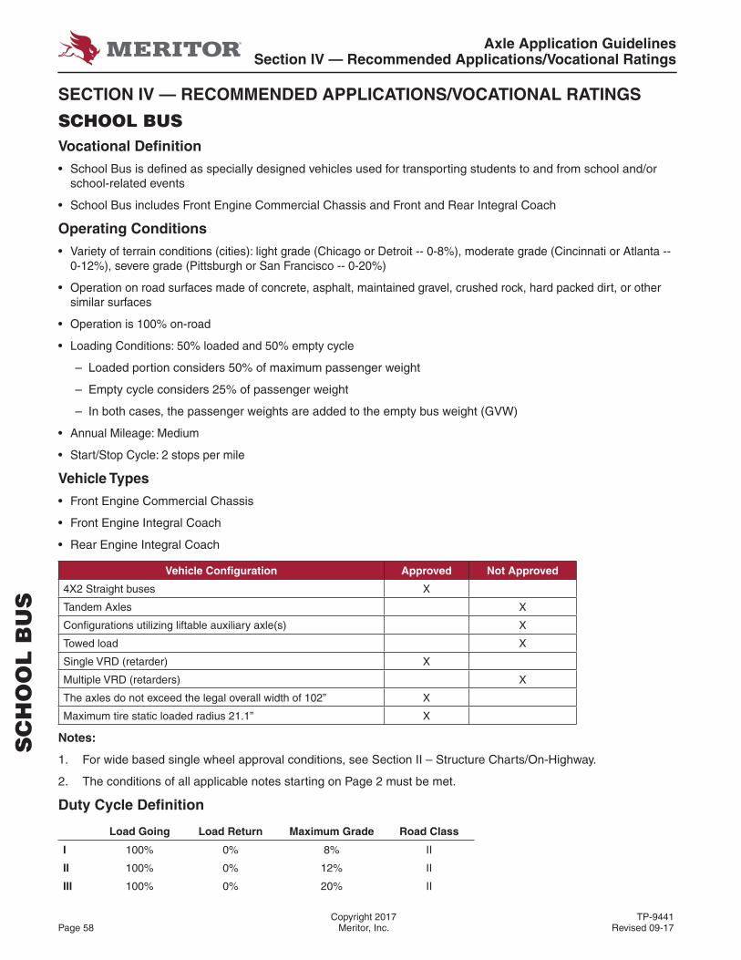
Axle Application GuidelinesSection IV — Recommended Applications/Vocational Ratings
Copyright 2017 TP-9441Page 58 Meritor, Inc. Revised 09-17
SECTION IV — RECOMMENDED APPLICATIONS/VOCATIONAL RATINGS
SCHOOL BUSVocational Defi nition
• School Bus is defi ned as specially designed vehicles used for transporting students to and from school and/or school-related events
• School Bus includes Front Engine Commercial Chassis and Front and Rear Integral Coach
Operating Conditions
• Variety of terrain conditions (cities): light grade (Chicago or Detroit -- 0-8%), moderate grade (Cincinnati or Atlanta -- 0-12%), severe grade (Pittsburgh or San Francisco -- 0-20%)
• Operation on road surfaces made of concrete, asphalt, maintained gravel, crushed rock, hard packed dirt, or other similar surfaces
• Operation is 100% on-road
• Loading Conditions: 50% loaded and 50% empty cycle
– Loaded portion considers 50% of maximum passenger weight
– Empty cycle considers 25% of passenger weight
– In both cases, the passenger weights are added to the empty bus weight (GVW)
• Annual Mileage: Medium
• Start/Stop Cycle: 2 stops per mile
Vehicle Types
• Front Engine Commercial Chassis
• Front Engine Integral Coach
• Rear Engine Integral Coach
Vehicle Confi guration Approved Not Approved
4X2 Straight buses X
Tandem Axles X
Confi gurations utilizing liftable auxiliary axle(s) X
Towed load X
Single VRD (retarder) X
Multiple VRD (retarders) X
The axles do not exceed the legal overall width of 102” X
Maximum tire static loaded radius 21.1” X
Notes:
1. For wide based single wheel approval conditions, see Section II – Structure Charts/On-Highway.
2. The conditions of all applicable notes starting on Page 2 must be met.
Duty Cycle Defi nition
Load Going Load Return Maximum Grade Road Class
I 100% 0% 8% II
II 100% 0% 12% II
III 100% 0% 20% II
SC
HO
OL
BU
S
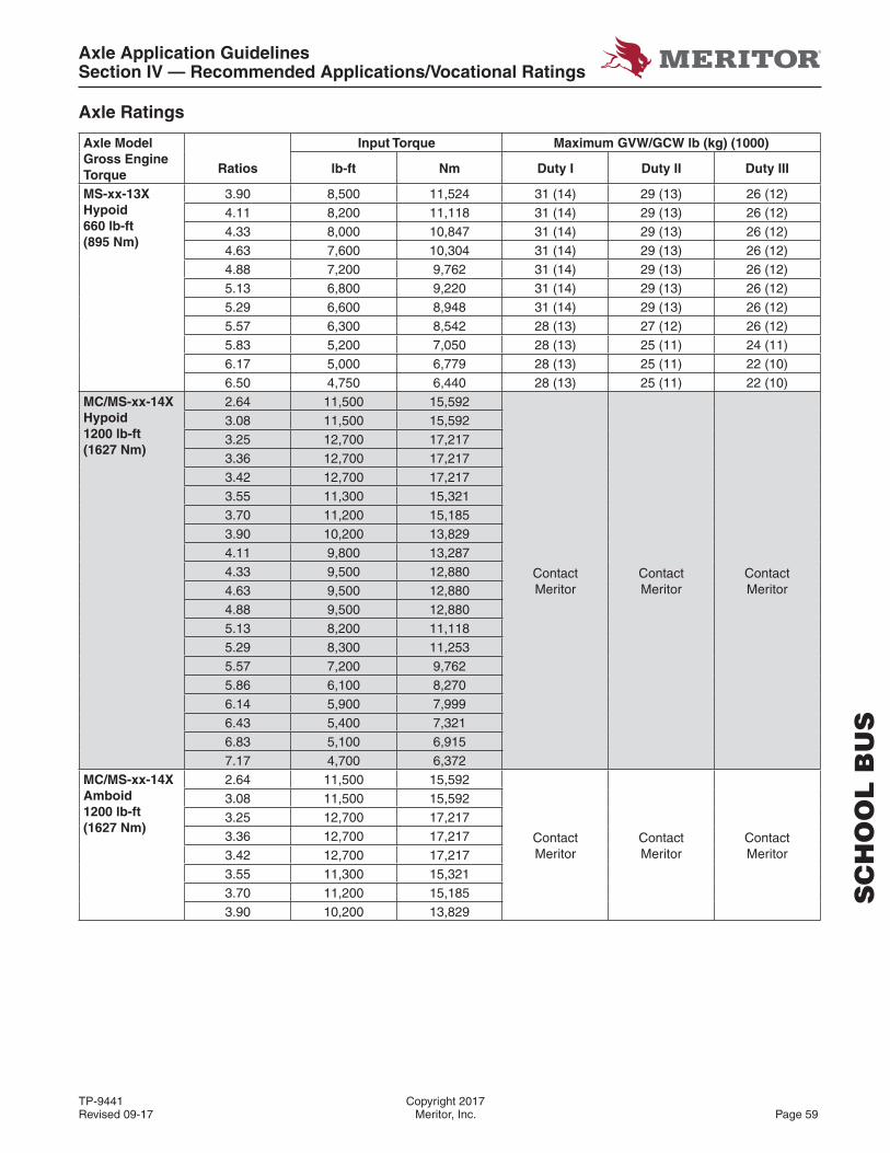
Axle Application GuidelinesSection IV — Recommended Applications/Vocational Ratings
TP-9441 Copyright 2017Revised 09-17 Meritor, Inc. Page 59
SC
HO
OL
BU
S
Axle Ratings
Axle Model Gross Engine Torque
Input Torque Maximum GVW/GCW lb (kg) (1000)
Ratios lb-ft Nm Duty I Duty II Duty III
MS-xx-13XHypoid660 lb-ft(895 Nm)
3.90 8,500 11,524 31 (14) 29 (13) 26 (12)4.11 8,200 11,118 31 (14) 29 (13) 26 (12)4.33 8,000 10,847 31 (14) 29 (13) 26 (12)4.63 7,600 10,304 31 (14) 29 (13) 26 (12)4.88 7,200 9,762 31 (14) 29 (13) 26 (12)5.13 6,800 9,220 31 (14) 29 (13) 26 (12)5.29 6,600 8,948 31 (14) 29 (13) 26 (12)5.57 6,300 8,542 28 (13) 27 (12) 26 (12)5.83 5,200 7,050 28 (13) 25 (11) 24 (11)6.17 5,000 6,779 28 (13) 25 (11) 22 (10)6.50 4,750 6,440 28 (13) 25 (11) 22 (10)
MC/MS-xx-14XHypoid1200 lb-ft(1627 Nm)
2.64 11,500 15,592
Contact Meritor
Contact Meritor
Contact Meritor
3.08 11,500 15,5923.25 12,700 17,2173.36 12,700 17,2173.42 12,700 17,2173.55 11,300 15,3213.70 11,200 15,1853.90 10,200 13,8294.11 9,800 13,2874.33 9,500 12,8804.63 9,500 12,8804.88 9,500 12,8805.13 8,200 11,1185.29 8,300 11,2535.57 7,200 9,7625.86 6,100 8,2706.14 5,900 7,9996.43 5,400 7,3216.83 5,100 6,9157.17 4,700 6,372
MC/MS-xx-14XAmboid1200 lb-ft(1627 Nm)
2.64 11,500 15,592
Contact Meritor
Contact Meritor
Contact Meritor
3.08 11,500 15,5923.25 12,700 17,2173.36 12,700 17,2173.42 12,700 17,2173.55 11,300 15,3213.70 11,200 15,1853.90 10,200 13,829
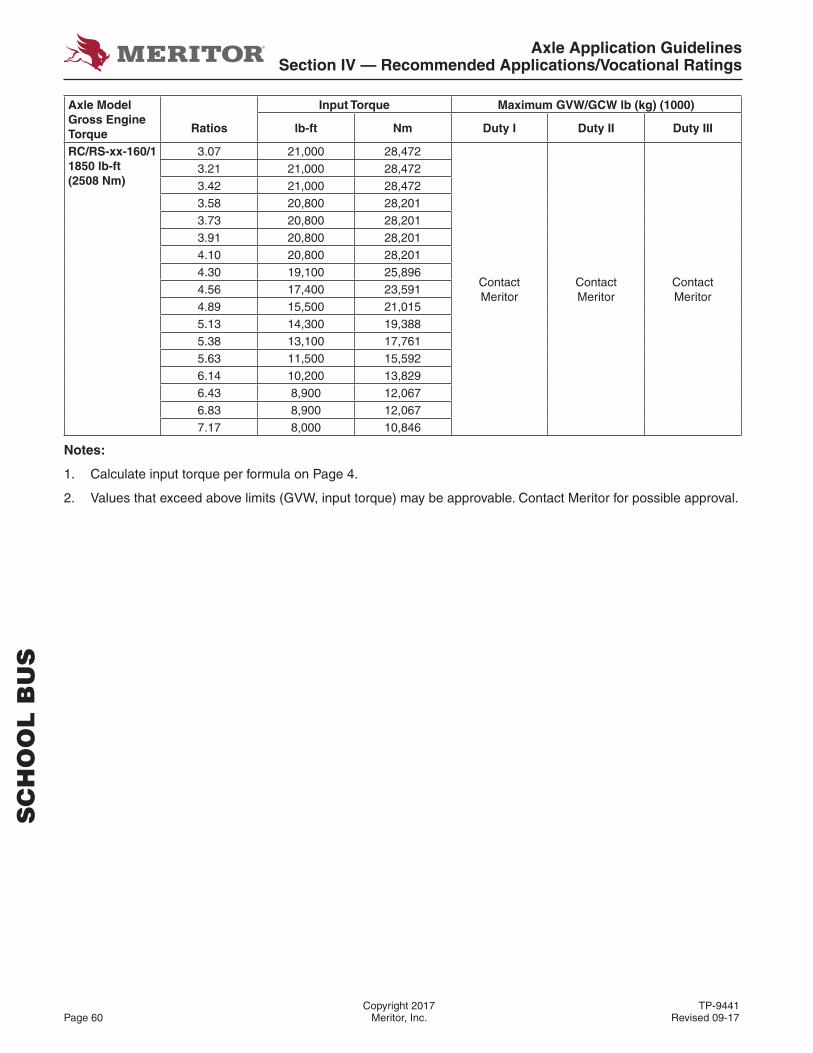
Axle Application GuidelinesSection IV — Recommended Applications/Vocational Ratings
Copyright 2017 TP-9441Page 60 Meritor, Inc. Revised 09-17
Axle Model Gross Engine Torque
Input Torque Maximum GVW/GCW lb (kg) (1000)
Ratios lb-ft Nm Duty I Duty II Duty III
RC/RS-xx-160/11850 lb-ft(2508 Nm)
3.07 21,000 28,472
Contact Meritor
Contact Meritor
Contact Meritor
3.21 21,000 28,4723.42 21,000 28,4723.58 20,800 28,2013.73 20,800 28,2013.91 20,800 28,2014.10 20,800 28,2014.30 19,100 25,8964.56 17,400 23,5914.89 15,500 21,0155.13 14,300 19,3885.38 13,100 17,7615.63 11,500 15,5926.14 10,200 13,8296.43 8,900 12,0676.83 8,900 12,0677.17 8,000 10,846
Notes:
1. Calculate input torque per formula on Page 4.
2. Values that exceed above limits (GVW, input torque) may be approvable. Contact Meritor for possible approval.
SC
HO
OL
BU
S
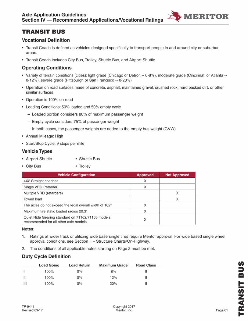
Axle Application GuidelinesSection IV — Recommended Applications/Vocational Ratings
TP-9441 Copyright 2017Revised 09-17 Meritor, Inc. Page 61
TRANSIT BUSVocational Defi nition
• Transit Coach is defi ned as vehicles designed specifi cally to transport people in and around city or suburban areas.
• Transit Coach includes City Bus, Trolley, Shuttle Bus, and Airport Shuttle
Operating Conditions
• Variety of terrain conditions (cities): light grade (Chicago or Detroit -- 0-8%), moderate grade (Cincinnati or Atlanta -- 0-12%), severe grade (Pittsburgh or San Francisco -- 0-20%)
• Operation on road surfaces made of concrete, asphalt, maintained gravel, crushed rock, hard packed dirt, or other similar surfaces
• Operation is 100% on-road
• Loading Conditions: 50% loaded and 50% empty cycle
– Loaded portion considers 80% of maximum passenger weight
– Empty cycle considers 75% of passenger weight
– In both cases, the passenger weights are added to the empty bus weight (GVW)
• Annual Mileage: High
• Start/Stop Cycle: 9 stops per mile
Vehicle Types
• Airport Shuttle • Shuttle Bus
• City Bus • Trolley
Vehicle Confi guration Approved Not Approved
4X2 Straight coaches X
Single VRD (retarder) X
Multiple VRD (retarders) X
Towed load X
The axles do not exceed the legal overall width of 102” X
Maximum tire static loaded radius 20.3” X
Quiet Ride Gearing standard on 71162/71163 models; recommended for all other axle models
X
Notes:
1. Ratings at wider track or utilizing wide base single tires require Meritor approval. For wide based single wheel approval conditions, see Section II – Structure Charts/On-Highway.
2. The conditions of all applicable notes starting on Page 2 must be met.
Duty Cycle Defi nition
Load Going Load Return Maximum Grade Road Class
I 100% 0% 8% II
II 100% 0% 12% II
III 100% 0% 20% II
TR
AN
SIT
BU
S
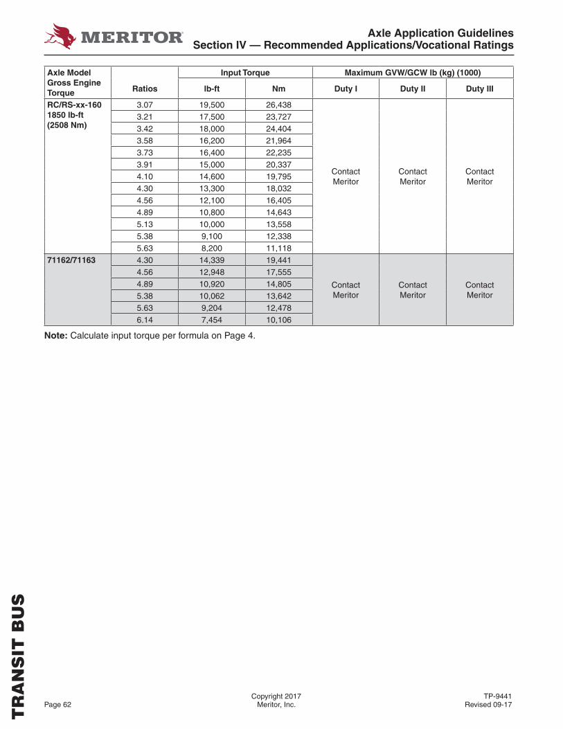
Axle Application GuidelinesSection IV — Recommended Applications/Vocational Ratings
Copyright 2017 TP-9441Page 62 Meritor, Inc. Revised 09-17
Axle Model Gross Engine Torque
Input Torque Maximum GVW/GCW lb (kg) (1000)
Ratios lb-ft Nm Duty I Duty II Duty III
RC/RS-xx-1601850 lb-ft(2508 Nm)
3.07 19,500 26,438
Contact Meritor
Contact Meritor
Contact Meritor
3.21 17,500 23,7273.42 18,000 24,4043.58 16,200 21,9643.73 16,400 22,2353.91 15,000 20,3374.10 14,600 19,7954.30 13,300 18,0324.56 12,100 16,4054.89 10,800 14,6435.13 10,000 13,5585.38 9,100 12,3385.63 8,200 11,118
71162/71163 4.30 14,339 19,441
Contact Meritor
Contact Meritor
Contact Meritor
4.56 12,948 17,5554.89 10,920 14,8055.38 10,062 13,6425.63 9,204 12,4786.14 7,454 10,106
Note: Calculate input torque per formula on Page 4.
TR
AN
SIT
BU
S
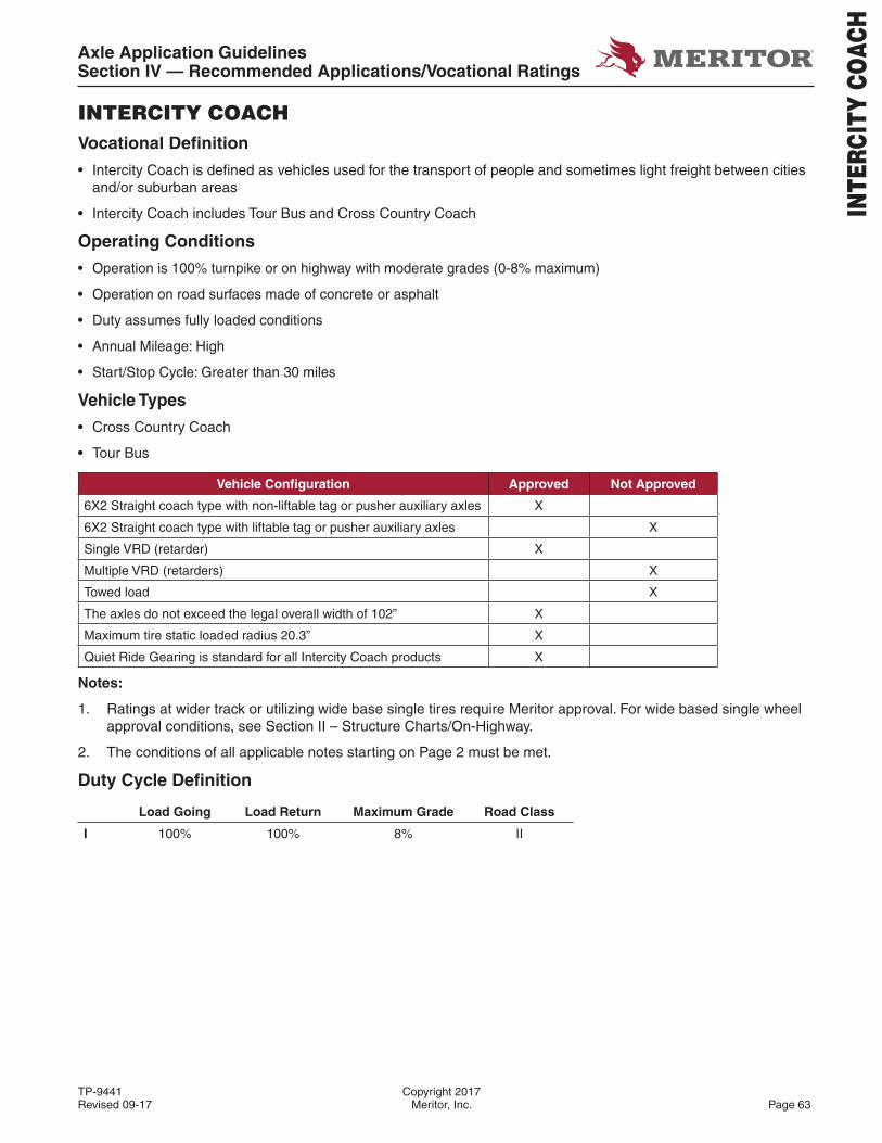
Axle Application GuidelinesSection IV — Recommended Applications/Vocational Ratings
TP-9441 Copyright 2017Revised 09-17 Meritor, Inc. Page 63
INTERCITY COACHVocational Defi nition
• Intercity Coach is defi ned as vehicles used for the transport of people and sometimes light freight between cities and/or suburban areas
• Intercity Coach includes Tour Bus and Cross Country Coach
Operating Conditions
• Operation is 100% turnpike or on highway with moderate grades (0-8% maximum)
• Operation on road surfaces made of concrete or asphalt
• Duty assumes fully loaded conditions
• Annual Mileage: High
• Start/Stop Cycle: Greater than 30 miles
Vehicle Types
• Cross Country Coach
• Tour Bus
Vehicle Confi guration Approved Not Approved
6X2 Straight coach type with non-liftable tag or pusher auxiliary axles X
6X2 Straight coach type with liftable tag or pusher auxiliary axles X
Single VRD (retarder) X
Multiple VRD (retarders) X
Towed load X
The axles do not exceed the legal overall width of 102” X
Maximum tire static loaded radius 20.3” X
Quiet Ride Gearing is standard for all Intercity Coach products X
Notes:
1. Ratings at wider track or utilizing wide base single tires require Meritor approval. For wide based single wheel approval conditions, see Section II – Structure Charts/On-Highway.
2. The conditions of all applicable notes starting on Page 2 must be met.
Duty Cycle Defi nition
Load Going Load Return Maximum Grade Road Class
I 100% 100% 8% II
INTE
RCIT
Y CO
ACH
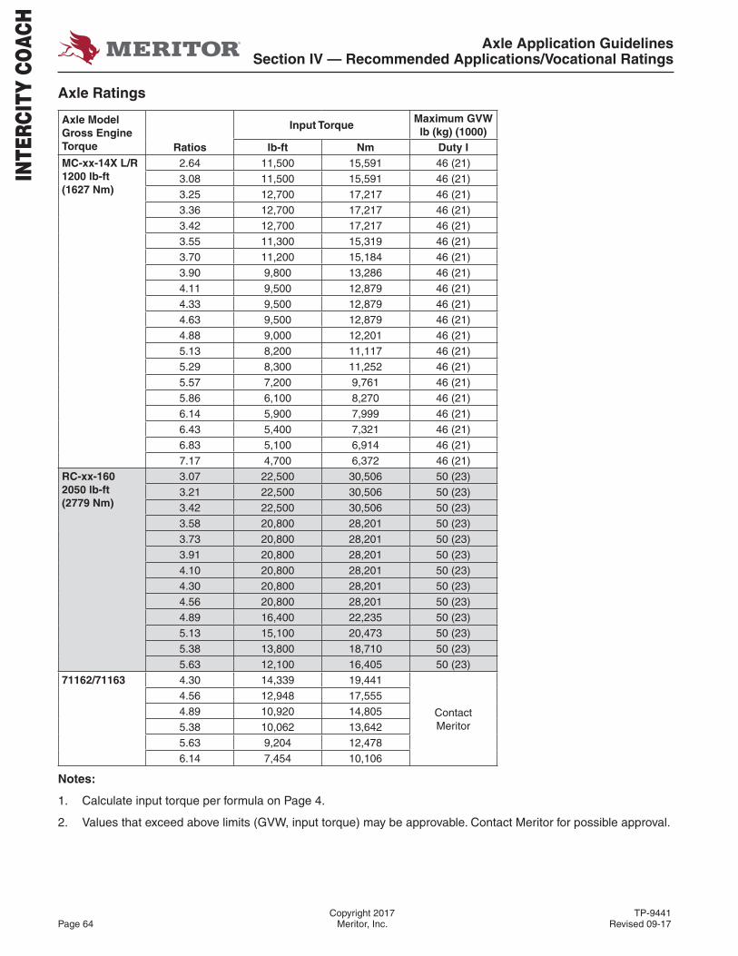
Axle Application GuidelinesSection IV — Recommended Applications/Vocational Ratings
Copyright 2017 TP-9441Page 64 Meritor, Inc. Revised 09-17
Axle Ratings
Axle Model Gross Engine Torque
Input TorqueMaximum GVW lb (kg) (1000)
Ratios lb-ft Nm Duty IMC-xx-14X L/R1200 lb-ft(1627 Nm)
2.64 11,500 15,591 46 (21)3.08 11,500 15,591 46 (21)3.25 12,700 17,217 46 (21)3.36 12,700 17,217 46 (21)3.42 12,700 17,217 46 (21)3.55 11,300 15,319 46 (21)3.70 11,200 15,184 46 (21)3.90 9,800 13,286 46 (21)4.11 9,500 12,879 46 (21)4.33 9,500 12,879 46 (21)4.63 9,500 12,879 46 (21)4.88 9,000 12,201 46 (21)5.13 8,200 11,117 46 (21)5.29 8,300 11,252 46 (21)5.57 7,200 9,761 46 (21)5.86 6,100 8,270 46 (21)6.14 5,900 7,999 46 (21)6.43 5,400 7,321 46 (21)6.83 5,100 6,914 46 (21)7.17 4,700 6,372 46 (21)
RC-xx-1602050 lb-ft(2779 Nm)
3.07 22,500 30,506 50 (23)3.21 22,500 30,506 50 (23)3.42 22,500 30,506 50 (23)3.58 20,800 28,201 50 (23)3.73 20,800 28,201 50 (23)3.91 20,800 28,201 50 (23)4.10 20,800 28,201 50 (23)4.30 20,800 28,201 50 (23)4.56 20,800 28,201 50 (23)4.89 16,400 22,235 50 (23)5.13 15,100 20,473 50 (23)5.38 13,800 18,710 50 (23)5.63 12,100 16,405 50 (23)
71162/71163 4.30 14,339 19,441
Contact Meritor
4.56 12,948 17,5554.89 10,920 14,8055.38 10,062 13,6425.63 9,204 12,4786.14 7,454 10,106
Notes:
1. Calculate input torque per formula on Page 4.
2. Values that exceed above limits (GVW, input torque) may be approvable. Contact Meritor for possible approval.
INTE
RCIT
Y CO
ACH

Axle Application GuidelinesSection IV — Recommended Applications/Vocational Ratings
TP-9441 Copyright 2017Revised 09-17 Meritor, Inc. Page 65
MO
TO
RH
OM
E
MOTORHOMEVocational Defi nition
• Motorhome is defi ned as recreational vehicles designed for transporting personal belongings
• Motorhome includes Recreational Vehicles and Integral Coach
• Reasonable towed loads (automobile, boat, etc.) are allowed
Operating Conditions
• Turnpike – Well maintained, multi-lane major highways of concrete or asphalt construction with max grade of 3.5%
• On Highway – Well maintained major highways of concrete or asphalt construction. Operation is subject to legal weight and dimensional limitations (permits included) with maximum positive or negative grades up to 8%
• Operation on road surfaces made of concrete, asphalt, maintained gravel, crushed rock, hard packed dirt, or other similar surfaces
• Operation is 100% on-road
• Duty assumes fully loaded conditions
• Annual Mileage: Low
• Start/Stop Cycle: Greater than 30 miles
Vehicle Types
• Integral Coach
• Recreational Vehicle
Vehicle Confi guration Approved Not Approved
4X2 Straight coach type X
6X2 Straight coach type with non-liftable tag or pusher auxiliary axles X
6X2 Straight coach type with liftable tag or pusher auxiliary axles X
Tandems X
Single VRD (retarder) X
Multiple VRD (retarders) X
Reasonable towed load (automobile, boat, etc.) X
“Quiet ride” gearing is recommended to prevent gear noise X
The axles do not exceed the legal overall width of 102” X
Maximum tire static loaded radius 21.1” X
Notes:
1. Unless otherwise authorized, ratings at wider track or utilizing wide base single tires require Meritor approval. For wide based single wheel approval conditions, see Section II – Structure Charts/On-Highway.
2. The conditions of all applicable notes starting on Page 2 must be met.
Duty Cycle Defi nition
Load Going Load Return Maximum Grade Road Class
I 100% 100% 3.5-8% I, II

Axle Application GuidelinesSection IV — Recommended Applications/Vocational Ratings
Copyright 2017 TP-9441Page 66 Meritor, Inc. Revised 09-17
Axle Ratings
Axle Model Gross Engine Torque
Input TorqueMaximum GVW lb (kg) (1000)
Ratios lb-ft Nm Duty IMS-xx-13X660 lb-ft(895 Nm)
3.90 8,500 11,524 40 (18)4.11 8,200 11,118 40 (18)4.33 8,000 10,847 40 (18)4.63 7,600 10,304 40 (18)4.88 7,200 9,762 40 (18)5.13 6,800 9,220 40 (18)5.29 6,600 8,948 40 (18)5.57 6,300 8,542 40 (18)5.83 5,200 7,050 35 (16)6.17 5,000 6,779 35 (16)6.50 4,750 6,440 35 (16)
MC/MS-xx-14XHypoid1200 lb-ft(1627 Nm)
2.64 13,600 18,439 46 (21)3.08 12,800 17,354 46 (21)3.25 12,700 17,217 46 (21)3.36 12,700 17,217 46 (21)3.42 12,700 17,217 46 (21)3.55 11,300 15,319 46 (21)3.70 11,200 15,184 46 (21)3.90 9,800 13,286 46 (21)4.11 9,500 12,879 46 (21)4.33 9,500 12,879 46 (21)4.63 9,500 12,879 46 (21)4.88 9,500 12,879 46 (21)5.13 8,600 11,660 46 (21)5.29 8,800 11,931 46 (21)5.57 7,600 10,304 46 (21)5.86 6,500 8,813 46 (21)6.14 6,200 8,406 46 (21)6.43 5,700 7,728 46 (21)6.83 5,400 7,321 46 (21)7.17 5,000 6,779 46 (21)
MO
TO
RH
OM
E
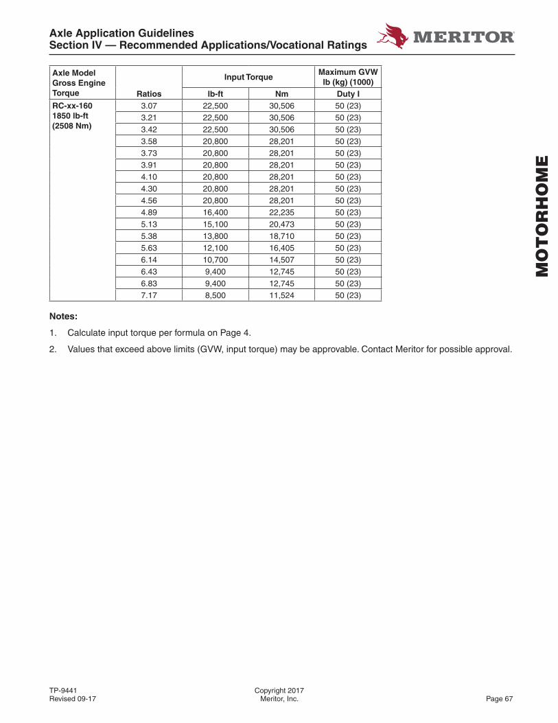
Axle Application GuidelinesSection IV — Recommended Applications/Vocational Ratings
TP-9441 Copyright 2017Revised 09-17 Meritor, Inc. Page 67
MO
TO
RH
OM
E
Axle Model Gross Engine Torque
Input TorqueMaximum GVW lb (kg) (1000)
Ratios lb-ft Nm Duty IRC-xx-1601850 lb-ft(2508 Nm)
3.07 22,500 30,506 50 (23)3.21 22,500 30,506 50 (23)3.42 22,500 30,506 50 (23)3.58 20,800 28,201 50 (23)3.73 20,800 28,201 50 (23)3.91 20,800 28,201 50 (23)4.10 20,800 28,201 50 (23)4.30 20,800 28,201 50 (23)4.56 20,800 28,201 50 (23)4.89 16,400 22,235 50 (23)5.13 15,100 20,473 50 (23)5.38 13,800 18,710 50 (23)5.63 12,100 16,405 50 (23)6.14 10,700 14,507 50 (23)6.43 9,400 12,745 50 (23)6.83 9,400 12,745 50 (23)7.17 8,500 11,524 50 (23)
Notes:
1. Calculate input torque per formula on Page 4.
2. Values that exceed above limits (GVW, input torque) may be approvable. Contact Meritor for possible approval.
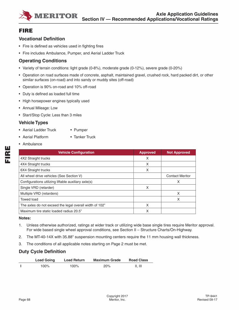
Axle Application GuidelinesSection IV — Recommended Applications/Vocational Ratings
Copyright 2017 TP-9441Page 68 Meritor, Inc. Revised 09-17
FIREVocational Defi nition
• Fire is defi ned as vehicles used in fi ghting fi res
• Fire includes Ambulance, Pumper, and Aerial Ladder Truck
Operating Conditions
• Variety of terrain conditions: light grade (0-8%), moderate grade (0-12%), severe grade (0-20%)
• Operation on road surfaces made of concrete, asphalt, maintained gravel, crushed rock, hard packed dirt, or other similar surfaces (on-road) and into sandy or muddy sites (off-road)
• Operation is 90% on-road and 10% off-road
• Duty is defi ned as loaded full time
• High horsepower engines typically used
• Annual Mileage: Low
• Start/Stop Cycle: Less than 3 miles
Vehicle Types
• Aerial Ladder Truck • Pumper
• Aerial Platform • Tanker Truck
• Ambulance
Vehicle Confi guration Approved Not Approved
4X2 Straight trucks X
4X4 Straight trucks X
6X4 Straight trucks X
All wheel drive vehicles (See Section V) Contact Meritor
Confi gurations utilizing liftable auxiliary axle(s) X
Single VRD (retarder) X
Multiple VRD (retarders) X
Towed load X
The axles do not exceed the legal overall width of 102” X
Maximum tire static loaded radius 20.5” X
Notes:
1. Unless otherwise authorized, ratings at wider track or utilizing wide base single tires require Meritor approval. For wide based single wheel approval conditions, see Section II – Structure Charts/On-Highway.
2. The MT-40-14X with 35.88" suspension mounting centers require the 11 mm housing wall thickness.
3. The conditions of all applicable notes starting on Page 2 must be met.
Duty Cycle Defi nition
Load Going Load Return Maximum Grade Road Class
I 100% 100% 20% II, III
FIR
E
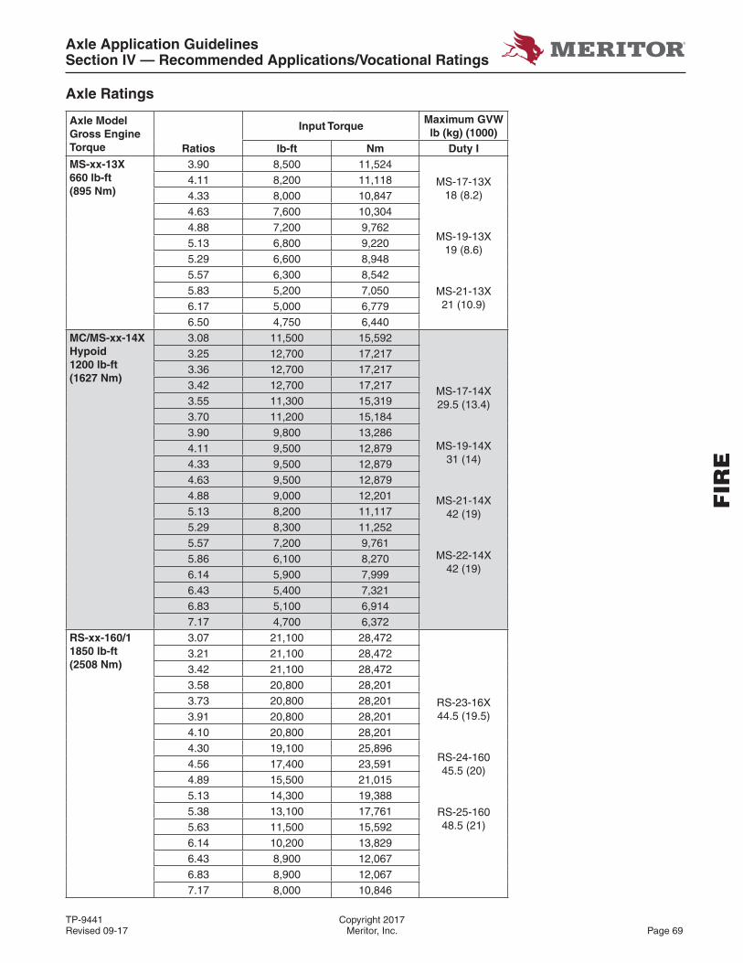
Axle Application GuidelinesSection IV — Recommended Applications/Vocational Ratings
TP-9441 Copyright 2017Revised 09-17 Meritor, Inc. Page 69
Axle Ratings
Axle Model Gross Engine Torque
Input TorqueMaximum GVW lb (kg) (1000)
Ratios lb-ft Nm Duty IMS-xx-13X660 lb-ft(895 Nm)
3.90 8,500 11,524
MS-17-13X18 (8.2)
MS-19-13X19 (8.6)
MS-21-13X21 (10.9)
4.11 8,200 11,1184.33 8,000 10,8474.63 7,600 10,3044.88 7,200 9,7625.13 6,800 9,2205.29 6,600 8,9485.57 6,300 8,5425.83 5,200 7,0506.17 5,000 6,7796.50 4,750 6,440
MC/MS-xx-14XHypoid1200 lb-ft(1627 Nm)
3.08 11,500 15,592
MS-17-14X29.5 (13.4)
MS-19-14X31 (14)
MS-21-14X42 (19)
MS-22-14X42 (19)
3.25 12,700 17,2173.36 12,700 17,2173.42 12,700 17,2173.55 11,300 15,3193.70 11,200 15,1843.90 9,800 13,2864.11 9,500 12,8794.33 9,500 12,8794.63 9,500 12,8794.88 9,000 12,2015.13 8,200 11,1175.29 8,300 11,2525.57 7,200 9,7615.86 6,100 8,2706.14 5,900 7,9996.43 5,400 7,3216.83 5,100 6,9147.17 4,700 6,372
RS-xx-160/11850 lb-ft(2508 Nm)
3.07 21,100 28,472
RS-23-16X44.5 (19.5)
RS-24-16045.5 (20)
RS-25-16048.5 (21)
3.21 21,100 28,4723.42 21,100 28,4723.58 20,800 28,2013.73 20,800 28,2013.91 20,800 28,2014.10 20,800 28,2014.30 19,100 25,8964.56 17,400 23,5914.89 15,500 21,0155.13 14,300 19,3885.38 13,100 17,7615.63 11,500 15,5926.14 10,200 13,8296.43 8,900 12,0676.83 8,900 12,0677.17 8,000 10,846
FIR
E
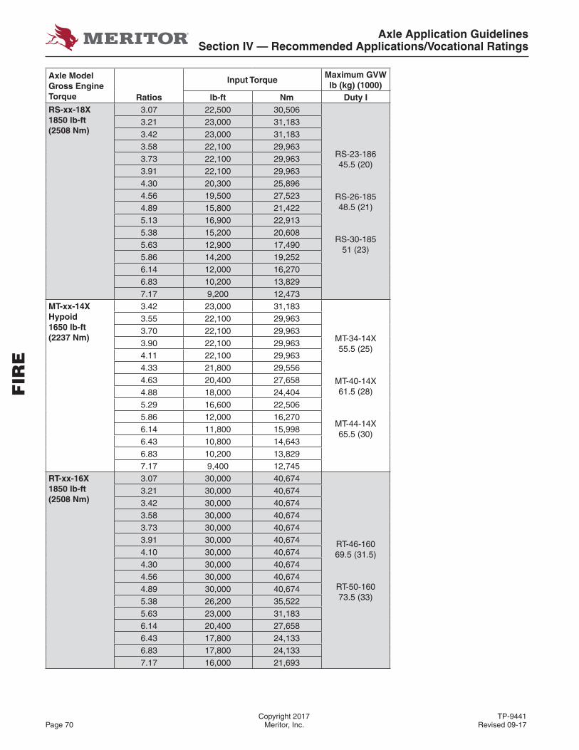
Axle Application GuidelinesSection IV — Recommended Applications/Vocational Ratings
Copyright 2017 TP-9441Page 70 Meritor, Inc. Revised 09-17
Axle Model Gross Engine Torque
Input TorqueMaximum GVW lb (kg) (1000)
Ratios lb-ft Nm Duty IRS-xx-18X1850 lb-ft(2508 Nm)
3.07 22,500 30,506
RS-23-18645.5 (20)
RS-26-18548.5 (21)
RS-30-18551 (23)
3.21 23,000 31,1833.42 23,000 31,1833.58 22,100 29,9633.73 22,100 29,9633.91 22,100 29,9634.30 20,300 25,8964.56 19,500 27,5234.89 15,800 21,4225.13 16,900 22,9135.38 15,200 20,6085.63 12,900 17,4905.86 14,200 19,2526.14 12,000 16,2706.83 10,200 13,8297.17 9,200 12,473
MT-xx-14XHypoid1650 lb-ft(2237 Nm)
3.42 23,000 31,183
MT-34-14X55.5 (25)
MT-40-14X61.5 (28)
MT-44-14X65.5 (30)
3.55 22,100 29,9633.70 22,100 29,9633.90 22,100 29,9634.11 22,100 29,9634.33 21,800 29,5564.63 20,400 27,6584.88 18,000 24,4045.29 16,600 22,5065.86 12,000 16,2706.14 11,800 15,9986.43 10,800 14,6436.83 10,200 13,8297.17 9,400 12,745
RT-xx-16X1850 lb-ft(2508 Nm)
3.07 30,000 40,674
RT-46-16069.5 (31.5)
RT-50-16073.5 (33)
3.21 30,000 40,6743.42 30,000 40,6743.58 30,000 40,6743.73 30,000 40,6743.91 30,000 40,6744.10 30,000 40,6744.30 30,000 40,6744.56 30,000 40,6744.89 30,000 40,6745.38 26,200 35,5225.63 23,000 31,1836.14 20,400 27,6586.43 17,800 24,1336.83 17,800 24,1337.17 16,000 21,693
FIR
E
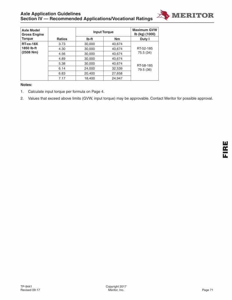
Axle Application GuidelinesSection IV — Recommended Applications/Vocational Ratings
TP-9441 Copyright 2017Revised 09-17 Meritor, Inc. Page 71
FIR
E
Axle Model Gross Engine Torque
Input TorqueMaximum GVW lb (kg) (1000)
Ratios lb-ft Nm Duty IRT-xx-18X1850 lb-ft(2508 Nm)
3.73 30,000 40,674RT-52-18575.5 (34)
RT-58-18579.5 (36)
4.30 30,000 40,6744.56 30,000 40,6744.89 30,000 40,6745.38 30,000 40,6746.14 24,000 32,5396.83 20,400 27,6587.17 18,400 24,947
Notes:
1. Calculate input torque per formula on Page 4.
2. Values that exceed above limits (GVW, input torque) may be approvable. Contact Meritor for possible approval.
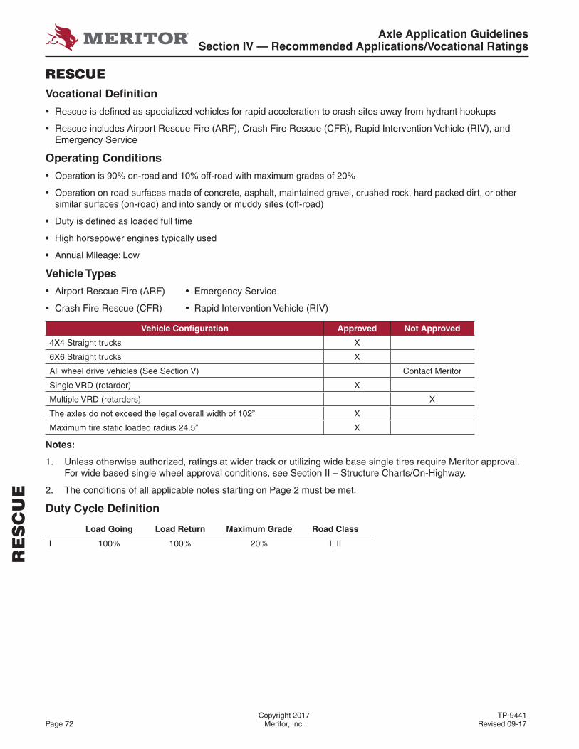
Axle Application GuidelinesSection IV — Recommended Applications/Vocational Ratings
Copyright 2017 TP-9441Page 72 Meritor, Inc. Revised 09-17
RESCUEVocational Defi nition
• Rescue is defi ned as specialized vehicles for rapid acceleration to crash sites away from hydrant hookups
• Rescue includes Airport Rescue Fire (ARF), Crash Fire Rescue (CFR), Rapid Intervention Vehicle (RIV), and Emergency Service
Operating Conditions
• Operation is 90% on-road and 10% off-road with maximum grades of 20%
• Operation on road surfaces made of concrete, asphalt, maintained gravel, crushed rock, hard packed dirt, or other similar surfaces (on-road) and into sandy or muddy sites (off-road)
• Duty is defi ned as loaded full time
• High horsepower engines typically used
• Annual Mileage: Low
Vehicle Types
• Airport Rescue Fire (ARF) • Emergency Service
• Crash Fire Rescue (CFR) • Rapid Intervention Vehicle (RIV)
Vehicle Confi guration Approved Not Approved
4X4 Straight trucks X
6X6 Straight trucks X
All wheel drive vehicles (See Section V) Contact Meritor
Single VRD (retarder) X
Multiple VRD (retarders) X
The axles do not exceed the legal overall width of 102” X
Maximum tire static loaded radius 24.5” X
Notes:
1. Unless otherwise authorized, ratings at wider track or utilizing wide base single tires require Meritor approval. For wide based single wheel approval conditions, see Section II – Structure Charts/On-Highway.
2. The conditions of all applicable notes starting on Page 2 must be met.
Duty Cycle Defi nition
Load Going Load Return Maximum Grade Road Class
I 100% 100% 20% I, II
RE
SC
UE
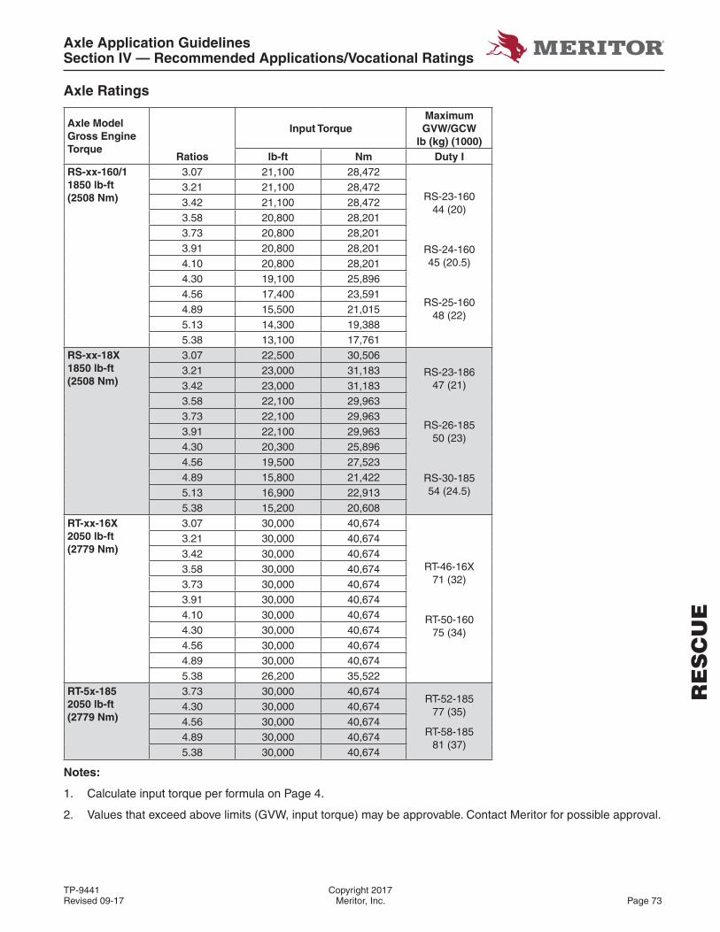
Axle Application GuidelinesSection IV — Recommended Applications/Vocational Ratings
TP-9441 Copyright 2017Revised 09-17 Meritor, Inc. Page 73
RE
SC
UE
Axle Ratings
Axle Model Gross Engine Torque
Input TorqueMaximum GVW/GCW
lb (kg) (1000)Ratios lb-ft Nm Duty I
RS-xx-160/11850 lb-ft(2508 Nm)
3.07 21,100 28,472
RS-23-16044 (20)
RS-24-16045 (20.5)
RS-25-16048 (22)
3.21 21,100 28,4723.42 21,100 28,4723.58 20,800 28,2013.73 20,800 28,2013.91 20,800 28,2014.10 20,800 28,2014.30 19,100 25,8964.56 17,400 23,5914.89 15,500 21,0155.13 14,300 19,3885.38 13,100 17,761
RS-xx-18X1850 lb-ft(2508 Nm)
3.07 22,500 30,506
RS-23-18647 (21)
RS-26-18550 (23)
RS-30-18554 (24.5)
3.21 23,000 31,1833.42 23,000 31,1833.58 22,100 29,9633.73 22,100 29,9633.91 22,100 29,9634.30 20,300 25,8964.56 19,500 27,5234.89 15,800 21,4225.13 16,900 22,9135.38 15,200 20,608
RT-xx-16X2050 lb-ft(2779 Nm)
3.07 30,000 40,674
RT-46-16X71 (32)
RT-50-16075 (34)
3.21 30,000 40,6743.42 30,000 40,6743.58 30,000 40,6743.73 30,000 40,6743.91 30,000 40,6744.10 30,000 40,6744.30 30,000 40,6744.56 30,000 40,6744.89 30,000 40,6745.38 26,200 35,522
RT-5x-1852050 lb-ft(2779 Nm)
3.73 30,000 40,674RT-52-185
77 (35)
RT-58-18581 (37)
4.30 30,000 40,6744.56 30,000 40,6744.89 30,000 40,6745.38 30,000 40,674
Notes:
1. Calculate input torque per formula on Page 4.
2. Values that exceed above limits (GVW, input torque) may be approvable. Contact Meritor for possible approval.
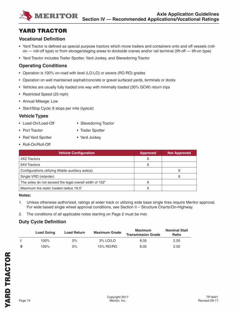
Axle Application GuidelinesSection IV — Recommended Applications/Vocational Ratings
Copyright 2017 TP-9441Page 74 Meritor, Inc. Revised 09-17
YARD TRACTORVocational Defi nition
• Yard Tractor is defi ned as special purpose tractors which move trailers and containers onto and off vessels (roll-on — roll-off type) or from storage/staging areas to dockside cranes and/or rail terminal (lift-off — lift-on type)
• Yard Tractor includes Trailer Spotter, Yard Jockey, and Stevedoring Tractor
Operating Conditions
• Operation is 100% on-road with level (LO-LO) or severe (RO-RO) grades
• Operation on well maintained asphalt/concrete or gravel surfaced yards, terminals or docks
• Vehicles are usually fully loaded one way with minimally loaded (30% GCW) return trips
• Restricted Speed (25 mph)
• Annual Mileage: Low
• Start/Stop Cycle: 6 stops per mile (typical)
Vehicle Types
• Load-On/Load-Off • Stevedoring Tractor
• Port Tractor • Trailer Spotter
• Rail Yard Spotter • Yard Jockey
• Roll-On/Roll-Off
Vehicle Confi guration Approved Not Approved
4X2 Tractors X
6X4 Tractors X
Confi gurations utilizing liftable auxiliary axle(s) X
Single VRD (retarder) X
The axles do not exceed the legal overall width of 102” X
Maximum tire static loaded radius 19.5” X
Notes:
1. Unless otherwise authorized, ratings at wider track or utilizing wide base single tires require Meritor approval. For wide based single wheel approval conditions, see Section II – Structure Charts/On-Highway.
2. The conditions of all applicable notes starting on Page 2 must be met.
Duty Cycle Defi nition
Load Going Load Return Maximum GradeMaximum
Transmission GradeNominal Stall
Ratio
I 100% 0% 3% LO/LO 8.05 2.50
II 100% 0% 15% RO/RO 8.05 2.50
YA
RD
TR
AC
TO
R
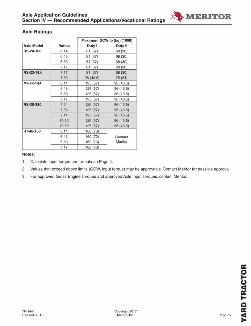
Axle Application GuidelinesSection IV — Recommended Applications/Vocational Ratings
TP-9441 Copyright 2017Revised 09-17 Meritor, Inc. Page 75
Axle Ratings
Maximum GCW lb (kg) (1000)Axle Model Ratios Duty I Duty IIRS-24-160 6.14 81 (37) 68 (30)
6.43 81 (37) 68 (30)6.83 81 (37) 68 (30)7.17 81 (37) 68 (30)
RS-23-18X 7.17 81 (37) 68 (30)7.83 96 (43.5) 75 (34)
MT-xx-14X 6.14 125 (57) 96 (43.5)6.43 125 (57) 96 (43.5)6.83 125 (57) 96 (43.5)7.17 125 (57) 96 (43.5)
RS-30-380 7.24 125 (57) 96 (43.5)7.83 125 (57) 96 (43.5)9.14 125 (57) 96 (43.5)10.12 125 (57) 96 (43.5)10.62 125 (57) 96 (43.5)
RT-46-160 6.14 160 (73)
ContactMeritor
6.43 160 (73)6.83 160 (73)7.17 160 (73)
Notes:
1. Calculate input torque per formula on Page 4.
2. Values that exceed above limits (GCW, input torque) may be approvable. Contact Meritor for possible approval.
3. For approved Gross Engine Torques and approved Axle Input Torques, contact Meritor.
YA
RD
TR
AC
TO
R
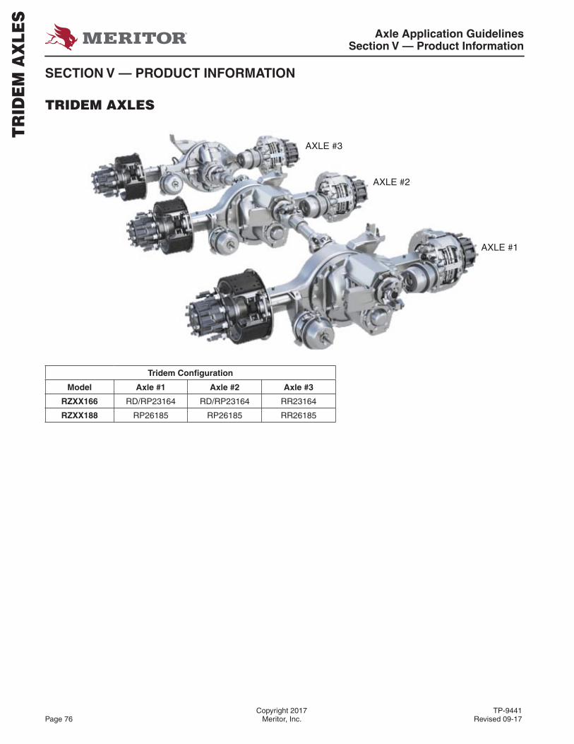
Axle Application GuidelinesSection V — Product Information
Copyright 2017 TP-9441Page 76 Meritor, Inc. Revised 09-17
SECTION V — PRODUCT INFORMATION
TRIDEM AXLES
Tridem Confi guration
Model Axle #1 Axle #2 Axle #3
RZXX166 RD/RP23164 RD/RP23164 RR23164
RZXX188 RP26185 RP26185 RR26185
TR
IDE
M A
XLE
S
AXLE #3
AXLE #2
AXLE #1
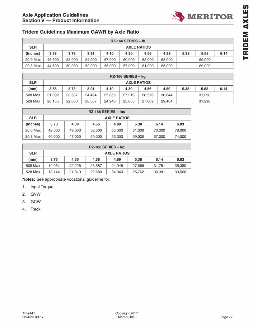
Axle Application GuidelinesSection V — Product Information
TP-9441 Copyright 2017Revised 09-17 Meritor, Inc. Page 77
Tridem Guidelines Maximum GAWR by Axle Ratio
RZ-166 SERIES – lb
SLR AXLE RATIOS
(Inches) 3.58 3.73 3.91 4.10 4.30 4.56 4.89 5.38 5.63 6.14
20.0 Max 46,500 52,000 54,000 57,000 60,000 63,000 68,000 69,000
20.8 Max 44,500 50,000 52,000 55,000 57,000 61,000 65,000 69,000
RZ-166 SERIES – kg
SLR AXLE RATIOS
(mm) 3.58 3.73 3.91 4.10 4.30 4.56 4.89 5.38 5.63 6.14
508 Max 21,092 23,587 24,494 25,855 27,216 28,576 30,844 31,298
528 Max 20,185 22,680 23,587 24,948 25,855 27,669 29,484 31,298
RZ-188 SERIES – lbs
SLR AXLE RATIOS
(Inches) 3.73 4.30 4.56 4.89 5.38 6.14 6.83
20.0 Max 42,000 49,000 52,000 55,000 61,000 70,000 78,000
20.8 Max 40,000 47,000 50,000 53,000 59,000 67,000 74,000
RZ-188 SERIES – kg
SLR AXLE RATIOS
(mm) 3.73 4.30 4.56 4.89 5.38 6.14 6.83
508 Max 19,051 22,226 23,587 24,948 27,669 31,751 35,380
528 Max 18,144 21,319 22,680 24,040 26,762 30,391 33,566
Notes: See appropriate vocational guideline for:
1. Input Torque
2. GVW
3. GCW
4. Track
TR
IDE
M A
XLE
S
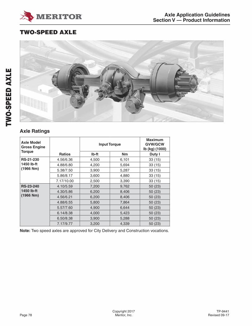
Axle Application GuidelinesSection V — Product Information
Copyright 2017 TP-9441Page 78 Meritor, Inc. Revised 09-17
TWO-SPEED AXLE
Axle Ratings
Axle Model Gross Engine Torque
Input TorqueMaximum GVW/GCW
lb (kg) (1000)Ratios lb-ft Nm Duty I
RS-21-2301450 lb-ft(1966 Nm)
4.56/6.36 4,500 6,101 33 (15)4.88/6.80 4,200 5,694 33 (15)5.38/7.50 3,900 5,287 33 (15)5.86/8.17 3,600 4,880 33 (15)7.17/10.00 2,500 3,390 33 (15)
RS-23-2401450 lb-ft(1966 Nm)
4.10/5.59 7,200 9,762 50 (23)4.30/5.86 6,200 8,406 50 (23)4.56/6.21 6,200 8,406 50 (23)4.88/6.55 5,800 7,864 50 (23)5.57/7.60 4,900 6,644 50 (23)6.14/8.38 4,000 5,423 50 (23)6.50/8.38 3,900 5,288 50 (23)7.17/9.77 3,200 4,339 50 (23)
Note: Two speed axles are approved for City Delivery and Construction vocations.
TWO
-SPE
ED A
XLE
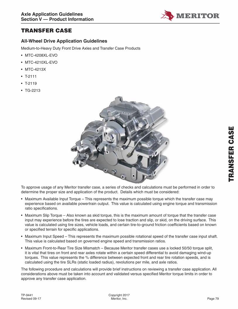
Axle Application GuidelinesSection V — Product Information
TP-9441 Copyright 2017Revised 09-17 Meritor, Inc. Page 79
TRANSFER CASE
All-Wheel Drive Application Guidelines
Medium-to-Heavy Duty Front Drive Axles and Transfer Case Products
• MTC-4208XL-EVO
• MTC-4210XL-EVO
• MTC-4213X
• T-2111
• T-2119
• TG-2213
To approve usage of any Meritor transfer case, a series of checks and calculations must be performed in order to determine the proper size and application of the product. Details which must be considered:
• Maximum Available Input Torque – This represents the maximum possible torque which the transfer case may experience based on available powertrain output. This value is calculated using engine torque and transmission ratio specifi cations.
• Maximum Slip Torque – Also known as skid torque, this is the maximum amount of torque that the transfer case input may experience before the tires are expected to lose traction and slip, or skid, on the driving surface. This value is calculated using tire sizes, vehicle loads, and certain tire-to-ground friction coeffi cients based on known or specifi ed terrain for specifi c applications.
• Maximum Input Speed – This represents the maximum possible rotational speed of the transfer case input shaft. This value is calculated based on governed engine speed and transmission ratios.
• Maximum Front-to-Rear Tire Size Mismatch – Because Meritor transfer cases use a locked 50/50 torque split, it is vital that tires on front and rear axles rotate within a certain speed differential to avoid damaging wind-up torques. This value represents the % difference between expected front and rear tire rotation speeds, and is calculated using the tire SLRs (static loaded radius), revolutions per mile, and axle ratios.
The following procedure and calculations will provide brief instructions on reviewing a transfer case application. All considerations above must be taken into account and validated versus specifi ed Meritor torque limits in order to approve any transfer case application.
TRA
NSF
ER C
ASE
Axle Application GuidelinesSection V — Product Information
Copyright 2017 TP-9441Page 80 Meritor, Inc. Revised 09-17
Single-Speed Transfer Cases Torque Analysis
Compare Torque Available (TA) and Total Slip Torque (TS,TOT) and take the lower of the two torque values. This torque must be less than the input torque rating of the selected Single Speed transfer case.
Note: In special instances, single speed transfer cases with optional ratios other than 1:1 may exist. In these cases the TS and TS,TOT,HI comparison should be made with the TS,TOT,HI value calculated with these optional transfer case ratios.
Two-Speed Transfer Case Torque Analysis
Compare Torque available (TA) and Total Slip Torque (TS,TOT,X) in HI and LO gear. The HI torque must be less than the maximum input torque for the HI gear rating and the LO torque must be less than the maximum input torque for the LO gear rating. (For two speed transfer case, “X” indicates HI or LOW gear for slip torque calculation.)
Torque Available at Transfer Case Input
TA = (0.92)(TE)(RTL)(RTC)
Where: TA = Theoretical Torque Available at Transfer Case Input (lb-ft)
TE = Gross Engine Torque (lb-ft)
RTL = Forward Low Ratio of Transmission (Use Reverse Low If High Torques Are Expected In Reverse)
RTC = Converter Stall Torque Ratio – Use 1.0 If No Converter Present
Total Slip Torque at Transfer Case Input (HI or LO)
TS,TOT,X = TSFX + TSRX
Where: TS,TOT,X = Total Slip Torque at Transfer Case (X indicates in HI or LO gear, for 2-speed Tcase)
TSF = (GAWF)(SLRF) (16)(ARF)(TCX)
TSR = (GAWR)(SLRR) (16)(ARR)(TCX)
TSF = Slip Torque of Transfer Case (lb-ft) - Front
TSR = Slip Torque of Transfer Case (lb-ft) - Rear
SLRF = Static Loaded Radius of Tires (Inch) - Front
SLRR = Static Loaded Radius of Tires (Inch) - Rear
ARF = Axle Ratio - Front
ARR = Axle Ratio - Rear
GAWF = Gross Axle Weight (lb) of Driving Units ONLY - Front
GAWR = Gross Axle Weight (lb) of Driving Units ONLY - Rear
TCX = Transfer Case HI or LO Ratio (See NOTES 1 and 2)
Notes:
1. “X” is incorporated into generic Two-Speed Transfer Case equations to indicate HI or LO.
2. Calculate both HI and LO results with Two-Speed Transfer Cases. Single-Speed Transfer Cases only require one calculation.
3. Slip torque calculations in HI gear are typically performed assuming a vehicle is in its LOADED condition with any liftable axles down and declutch DISENGAGED.
4. Slip torque calculations in LOW gear are typically performed assuming a vehicle is in its OVERLOADED condition with any liftable axles up and declutch ENGAGED.
TRA
NSF
ER C
ASE
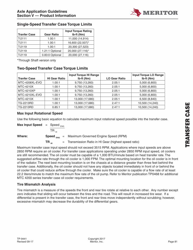
Axle Application GuidelinesSection V — Product Information
TP-9441 Copyright 2017Revised 09-17 Meritor, Inc. Page 81
Single-Speed Transfer Case Torque Limits
Tranfer Case Gear RatioInput Torque Rating
lb-ft (Nm)T-2111 1.00:1 11,000 (14,914)T-2111 1.00:1 16,600 (22,507)*T-2119 1.00:1 20,300 (27,523)T-2119 1.21:1 Optional 20,000 (27,116)*T-2119 0.83:0 Optional 20,000 (27,116)
*Through Shaft version only
Two-Speed Transfer Case Torque Limits
Tranfer Case HI Gear RatioInput Torque HI Range
lb-ft (Nm) LO Gear RatioInput Torque LO Range
lb-ft (Nm)MTC-4208XL-EVO 1.00:1 9,750 (13,260) 2.05:1 5,000 (6,800)MTC-4210X 1.00:1 9,750 (13,260) 2.05:1 5,000 (6,800)MTC-4210XP 1.00:1 9,750 (13,260) 2.05:1 5,000 (6,800)MTC-4210XL-EVO 1.00:1 9,750 (13,260) 2.05:1 5,000 (6,800)MTC-4213X 1.00:1 13,000 (17,680) 2.05:1 6,500 (8,840)TG-2213RD 1.00:1 13,000 (17,680) 2.47:1 10,500 (14,240)TG-2213RD 0.85:1 13,000 (17,680) 2.47:1 10,500 (14,240)
Max Input Rotational Speed
Use the following basic equation to calculate maximum input rotational speed possible into the transfer case.
Max Input Speed = Speed ENG
TR HI
Where: Speed ENG = Maximum Governed Engine Speed (RPM)
TR HI = Transmission Ratio in HI Gear (highest speed ratio)
Maximum transfer case input speed should not exceed 3515 RPM. Applications where input speeds are above 2850 RPM require an oil cooler. For transfer case applications operating under 2850 RPM input speed, oil coolers are still recommended. The oil cooler must be capable of a 1,000 BTU/minute based on heat transfer rate. The suggested airfl ow rate through the oil cooler is 1,000 FPM. The optimal mounting location for the oil cooler is in front of the radiator. The next best mounting location is on the chassis at a distance greater than three feet behind the transfer case. Additionally, the oil cooler should not have any objects located immediately in front of or behind the oil cooler that could reduce airfl ow through the cooler. Make sure the oil cooler is capable of a fl ow rate of at least 22.2 liters/minute to match the maximum fl ow rate of the oil pump. Refer to Meritor publication TP0468 for additional MTC 4200 series transfer case oil cooler requirements.
Tire Mismatch Analysis
Tire mismatch is a measure of the speeds the front and rear tire rotate at relative to each other. Any number except zero indicates that sliding will occur between the tires and the road. This will result in increased tire wear. If a differential is present in the transfer case, the front and rear tires move independently without scrubbing; however, excessive mismatch may decrease the durability of the differential gears.
TRA
NSF
ER C
ASE
Axle Application GuidelinesSection V — Product Information
Copyright 2017 TP-9441Page 82 Meritor, Inc. Revised 09-17
TRA
NSF
ER C
ASE
Low Speed Mismatch
The following formula is used to calculate mismatch at low speeds before tire expansion occurs. This assumes normal usage of a transfer case with one axle, usually the front, disengaged at higher operating speeds.
% Mismatch LO = [(SLRF)(ARR) - (SLRR)(ARF)] x 100
(SLRF)(ARR)
Where: SLRF = Static Loaded Radius of Tires (Inch) - Front
SLRR = Static Loaded Radius of Tires (Inch) - Rear
ARF = Axle Ratio - Front
ARR = Axle Ratio - Rear
High Speed Mismatch
The following formula is used to calculate mismatch at high speeds and is considered only when the front driving axle is engaged at high speeds. Normally the front driving axle is declutched in this condition. This calculation, therefore, is only required for Transfer Cases which include a differential and operate the front driving axle on a full time basis.
% Mismatch HI = [(TRPMR)(ARR) - (TRPMF)(ARF)] x 100
(TRPMR)(ARR)
Where: TRPMF = Tire Revs Per Mile - Front
TRPMR = Tire Revs Per Mile - Rear
ARF = Axle Ratio - Front
ARR = Axle Ratio - Rear
Notes: Meritor requires the mismatch between front and rear driving axles not exceed ± 2.0% for high speed mismatch and ± 1.5% for low speed mismatch for declutchable transfer cases without a differential, and ± 3.0% mismatch for units with a differential. If the Transfer Case has neither a clutch nor differential, mismatch must be under ± 1% high or low speed.
(When mismatch calculations result in a positive value, the front axle is pulling. A negative value indicates that the rear axle is pushing. A positive mismatch is the preferred condition for vehicle safety and improved steering.)
Meritor will only approve a mismatch between 0 and +3% between the front and rear driving axles for snow plow vocations. Further, AWD engagement should not exceed more than 20% of mileage on an annual basis for any plowing vocations.
Notes: In addition to the required application calculations, other considerations should be taken into account by any truck supplier or OEM installing a Meritor transfer case, such as vehicle packaging, driveline angles, and driveline rotation. The following notes should be reviewed for validation before applicating any Meritor transfer case.
1. Driveline Angles – Driveline angles between powertrain and transfer case (tcase input), and between transfer case and drive axles (tcase output) should be reviewed and meet all interacting component requirements. For Meritor drivelines, the maximum allowable joint angle is 6 degrees. With two jointed drivelines, the difference in angles between both joints must not exceed 1.5 degrees.
2. Packaging – The OEM has the responsibility of determining the proper transfer case mounting location and specifi cations in order to meet driveline angle requirements, vehicle packaging clearance, and structural stability.
3. Mounting Brackets – The OEM is responsible for validation of proper transfer case mounting brackets. The brackets that mount the transfer case to the vehicle play an important role in the overall vehicle performance. Their stiffness stabilizes the transfer case housing and also determines drivetrain vibration transmission.
Axle Application GuidelinesSection V — Product Information
TP-9441 Copyright 2017Revised 09-17 Meritor, Inc. Page 83
4. Proper Input Rotation – The OEM has the responsibility of verifying that the transfer case is mounted in such a way that the proper rotation will be translated through the drivetrain in order to drive front and rear axles, moving the vehicle in the appropriate direction.
5. Part-time Operation – Because Meritor’s MTC series transfer cases are designed without a proportional differential, only engage 4x4 or 6x6 operation on a part-time basis. “Part-time is defi ned as front axle engagement for less than 20% of the vehicles mileage over an annual basis. Operate the vehicle at speeds less than 25 MPH (40 km/h) when part-time 4x4 or 6x6 operation is engaged. Only engage 4x4 or 6x6 operation under slippery conditions where more traction is required, such as deep snow, ice, off-road or steep grades. 4x4 or 6x6 should not be engaged under normal operating conditions such as dry pavement, wet pavement, or hard packed dirt.
6. Towing – when towing a vehicle equipped with a Meritor transfer case, remove both axle shafts from the vehicle that will remain on the road while vehicle is being transported, or remove the drive shaft from axles that will be in contact with the ground. Refer to Meritor publication TP-9579 for complete towing information and instructions.
7. Power Take Off (PTO) Units – Refer to Meritor publications TP0708 and TP01137 for information and instructions pertaining to operation and usage of PTO assemblies.
8. Tcase Operation – OEMs and vehicle operators should refer to and comply with Meritor publications TP1075, TP0468, and TP0938 in regards to operation of Meritor transfer case products. Visit Meritor.com (customer center - literature on demand) for access to all publications and maintenance manuals on Meritor products.
9. Where a chassis is being sold as an incomplete vehicle, it is the responsibility of the OEM and/or dealer to accurately convey all approved transfer case selection information, including GVW and GAWR limitations, to the builder.
10. Vehicles operating outside of an approved Meritor application, such as a different vocation, drivetrain confi guration, load distribution changes, and testing of any kind, are not covered by Meritor’s warranty. For complete details and specifi c coverage, refer to Meritor publication SP-95155, Commercial Vehicle Systems Warranty.
TRA
NSF
ER C
ASE
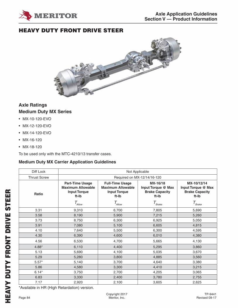
Axle Application GuidelinesSection V — Product Information
Copyright 2017 TP-9441Page 84 Meritor, Inc. Revised 09-17
HEA
VY
DU
TY F
RO
NT
DR
IVE
STEE
R
HEAVY DUTY FRONT DRIVE STEER
Axle RatingsMedium Duty MX Series
• MX-10-120-EVO
• MX-12-120-EVO
• MX-14-120-EVO
• MX-16-120
• MX-18-120
To be used only with the MTC-4210/13 transfer cases.
Medium Duty MX Carrier Application Guidelines
Diff Lock Not Applicable
Thrust Screw Required on MX-12/14/16-120
Ratio
Part-Time Usage Maximum Allowable
Input Torque ft-lb
TAllow
Full-Time Usage Maximum Allowable
Input Torque ft-lb
TAllow
MX-16/18 Input Torque @ Max
Brake Capacity ft-lb
TBrake
MX-10/12/14Input Torque @ Max
Brake Capacityft-lb
TBrake
3.31 9,310 6,700 7,805 5,6903.58 8,190 5,900 7,215 5,2603.73 8,750 6,300 6,925 5,0503.91 7,080 5,100 6,605 4,8154.10 7,640 5,500 6,300 4,5954.30 6,390 4,600 6,010 4,380
4.56 6,530 4,700 5,665 4,130
4.88* 6,110 4,400 5,295 3,8605.13 5,690 4,100 5,035 3,6705.29 5,280 3,800 4,885 3,5605.57* 5,140 3,700 4,640 3,3805.86 4,580 3,300 4,410 3,2156.14* 3,750 2,700 4,205 3,0656.83 3,330 2,400 3,780 2,7557.17 2,920 2,100 3,605 2,625
*Available in HR (High Retardation) version.

Axle Application GuidelinesSection V — Product Information
TP-9441 Copyright 2017Revised 09-17 Meritor, Inc. Page 85
Heavy Duty MX Series
• MX-17-140
• MX-19-140
• MX-21-140
Heavy Duty MX-140 Carrier Application Guidelines – Part-Time Use
Diff Lock Not Applicable
Thrust Screw Required on MX-12/14/16-120
Pinion Position DIRDL or DIRUR
RatioMaximum Allowable Input Torque (lb-ft) Input Torque @ Max Brake Capacity (lb-ft)
DIRDL DIRUR* Type 24 Type 30
3.42 12,300 17,640 7,554 8,967
3.58 10,900 15,690 7,216 8,566
3.73 10,800 15,560 6,926 8,222
3.91 9,900 14,170 6,607 7,843
4.10 9,500 13,610 6,301 7,480
4.33 9,200 13,190 5,966 7,082
4.63 9,200 13,190 5,580 6,623
4.88 8,800 12,500 5,294 6,284
5.13 7,800 11,390 5,036 5,978
5.29 8,000 11,530 4,883 5,797
5.57 7,000 10,000 4,638 5,506
5.86 6,000 8,470 4,408 5,233
6.14 5,700 8,190 4,207 4,995
6.43 5,200 7,500 4,018 4,769
6.83 4,900 7,080 3,782 4,490
7.17 4,500 6,530 3,603 4,277
* Reverse input rotation required.
Typical Pinion Layout
A B
Gearing Standard Standard
Tooth Contact – Front Coast Side Drive Side
Tooth Contact – Rear Drive Side Coast Side
Input Rotation – Front1 CCW CW
Input Rotation – Rear1 CW CCW
Input Location DIRDL DIRUR
Note: Contact your sales person for Tandem Axle ratio availability.
HEA
VY
DU
TY F
RO
NT
DR
IVE
STEE
R
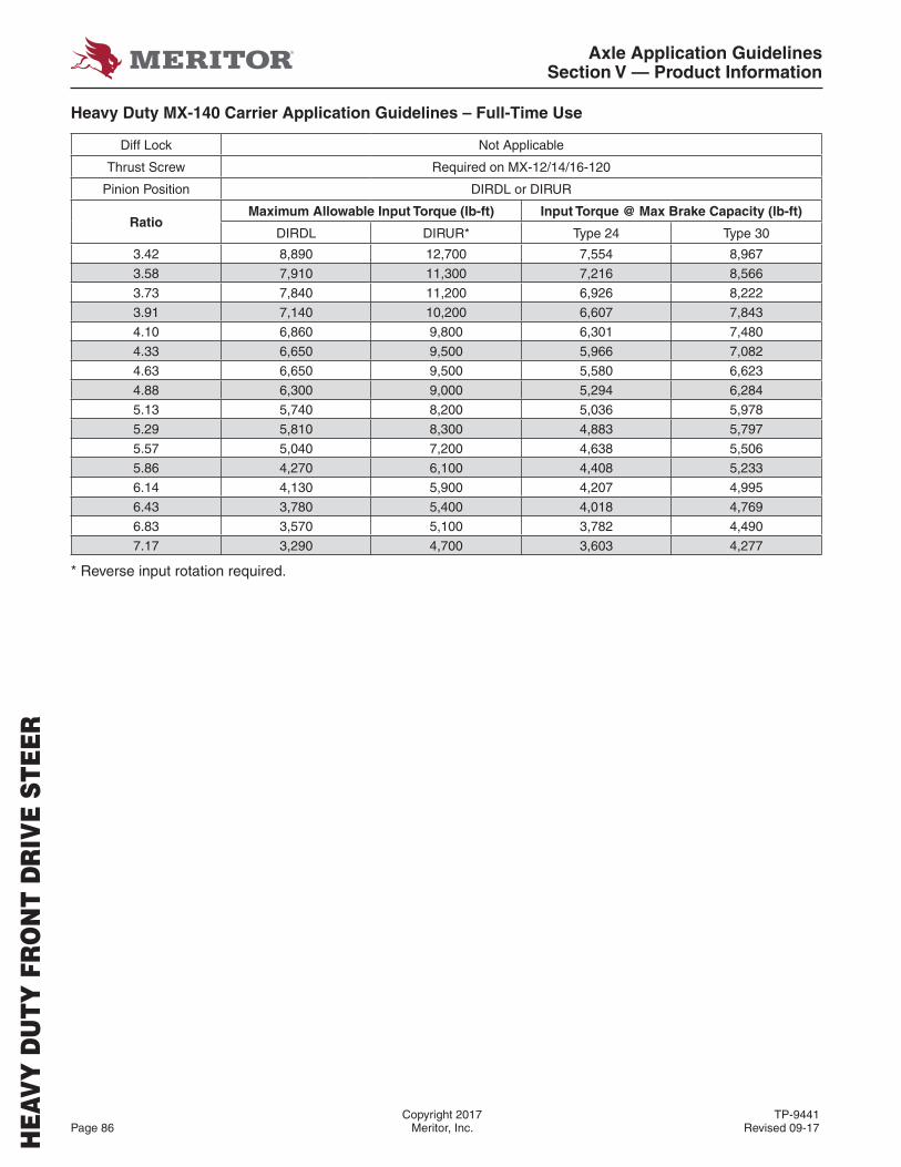
Axle Application GuidelinesSection V — Product Information
Copyright 2017 TP-9441Page 86 Meritor, Inc. Revised 09-17
HEA
VY
DU
TY F
RO
NT
DR
IVE
STEE
R
Heavy Duty MX-140 Carrier Application Guidelines – Full-Time Use
Diff Lock Not Applicable
Thrust Screw Required on MX-12/14/16-120
Pinion Position DIRDL or DIRUR
RatioMaximum Allowable Input Torque (lb-ft) Input Torque @ Max Brake Capacity (lb-ft)
DIRDL DIRUR* Type 24 Type 30
3.42 8,890 12,700 7,554 8,967
3.58 7,910 11,300 7,216 8,566
3.73 7,840 11,200 6,926 8,222
3.91 7,140 10,200 6,607 7,843
4.10 6,860 9,800 6,301 7,480
4.33 6,650 9,500 5,966 7,082
4.63 6,650 9,500 5,580 6,623
4.88 6,300 9,000 5,294 6,284
5.13 5,740 8,200 5,036 5,978
5.29 5,810 8,300 4,883 5,797
5.57 5,040 7,200 4,638 5,506
5.86 4,270 6,100 4,408 5,233
6.14 4,130 5,900 4,207 4,995
6.43 3,780 5,400 4,018 4,769
6.83 3,570 5,100 3,782 4,490
7.17 3,290 4,700 3,603 4,277
* Reverse input rotation required.
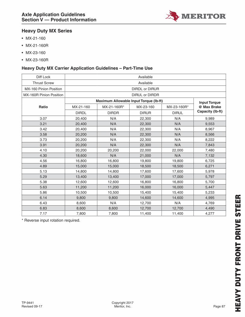
Axle Application GuidelinesSection V — Product Information
TP-9441 Copyright 2017Revised 09-17 Meritor, Inc. Page 87
Heavy Duty MX Series
• MX-21-160
• MX-21-160R
• MX-23-160
• MX-23-160R
Heavy Duty MX Carrier Application Guidelines – Part-Time Use
Diff Lock Available
Thrust Screw Available
MX-160 Pinion Position DIRDL or DIRUR
MX-160R Pinion Position DIRUL or DIRDR
Ratio
Maximum Allowable Input Torque (lb-ft) Input Torque @ Max Brake
Capacity (lb-ft)MX-21-160 MX-21-160R* MX-23-160 MX-23-160R*
DIRDL DIRDR DIRUR DIRUL
3.07 20,400 N/A 22,300 N/A 9,989
3.21 20,400 N/A 22,300 N/A 9,553
3.42 20,400 N/A 22,300 N/A 8,967
3.58 20,200 N/A 22,300 N/A 8,566
3.73 20,200 N/A 22,300 N/A 8,222
3.91 20,200 N/A 22,300 N/A 7,843
4.10 20,200 20,200 22,000 22,000 7,480
4.30 18,600 N/A 21,000 N/A 7,132
4.56 16,800 16,800 19,800 19,800 6,725
4.89 15,000 15,000 18,500 18,500 6,271
5.13 14,800 14,800 17,600 17,600 5,978
5.29 13,400 13,400 17,000 17,000 5,797
5.38 12,600 12,600 16,800 16,800 5,700
5.63 11,200 11,200 16,000 16,000 5,447
5.86 10,500 10,500 15,400 15,400 5,233
6.14 9,800 9,800 14,600 14,600 4,995
6.43 8,600 N/A 12,700 N/A 4,769
6.83 8,600 8,600 12,700 12,700 4,490
7.17 7,800 7,800 11,400 11,400 4,277
* Reverse input rotation required.
HEA
VY
DU
TY F
RO
NT
DR
IVE
STEE
R

Axle Application GuidelinesSection V — Product Information
Copyright 2017 TP-9441Page 88 Meritor, Inc. Revised 09-17
HEA
VY
DU
TY F
RO
NT
DR
IVE
STEE
R
Heavy Duty MX Carrier Application Guidelines – Part-Time Use
Diff Lock Available
Thrust Screw Available
MX-160 Pinion Position DIRDL or DIRUR
MX-160R Pinion Position DIRUL or DIRDR
Ratio
Maximum Allowable Input Torque (lb-ft) Input Torque @ Max Brake
Capacity (lb-ft)MX-21-160 MX-21-160R* MX-23-160 MX-23-160R*
DIRDL DIRDR DIRUR DIRUL
3.07 14,700 N/A 21,000 N/A 9,989
3.21 14,700 N/A 21,000 N/A 9,553
3.42 14,700 N/A 21,000 N/A 8,967
3.58 14,550 N/A 20,800 N/A 8,566
3.73 14,550 N/A 20,800 N/A 8,222
3.91 14,550 N/A 20,800 N/A 7,843
4.10 14,550 14,550 20,800 20,800 7,480
4.30 13,400 N/A 19,100 N/A 7,132
4.56 12,200 12,200 17,400 17,400 6,725
4.89 10,850 10,850 15,500 15,500 6,271
5.13 10,650 10,650 15,200 15,200 5,978
5.29 9,650 9,650 13,800 13,800 5,797
5.38 9,200 9,200 13,100 13,100 5,700
5.63 8,050 8,050 11,500 11,500 5,447
5.86 7,550 7,550 10,800 10,800 5,233
6.14 7,150 7,150 10,200 10,200 4,995
6.43 6,250 N/A 8,900 N/A 4,769
6.83 6,250 6,250 8,900 8,900 4,490
7.17 5,600 5,600 8,000 8,000 4,277
* Reverse input rotation required.
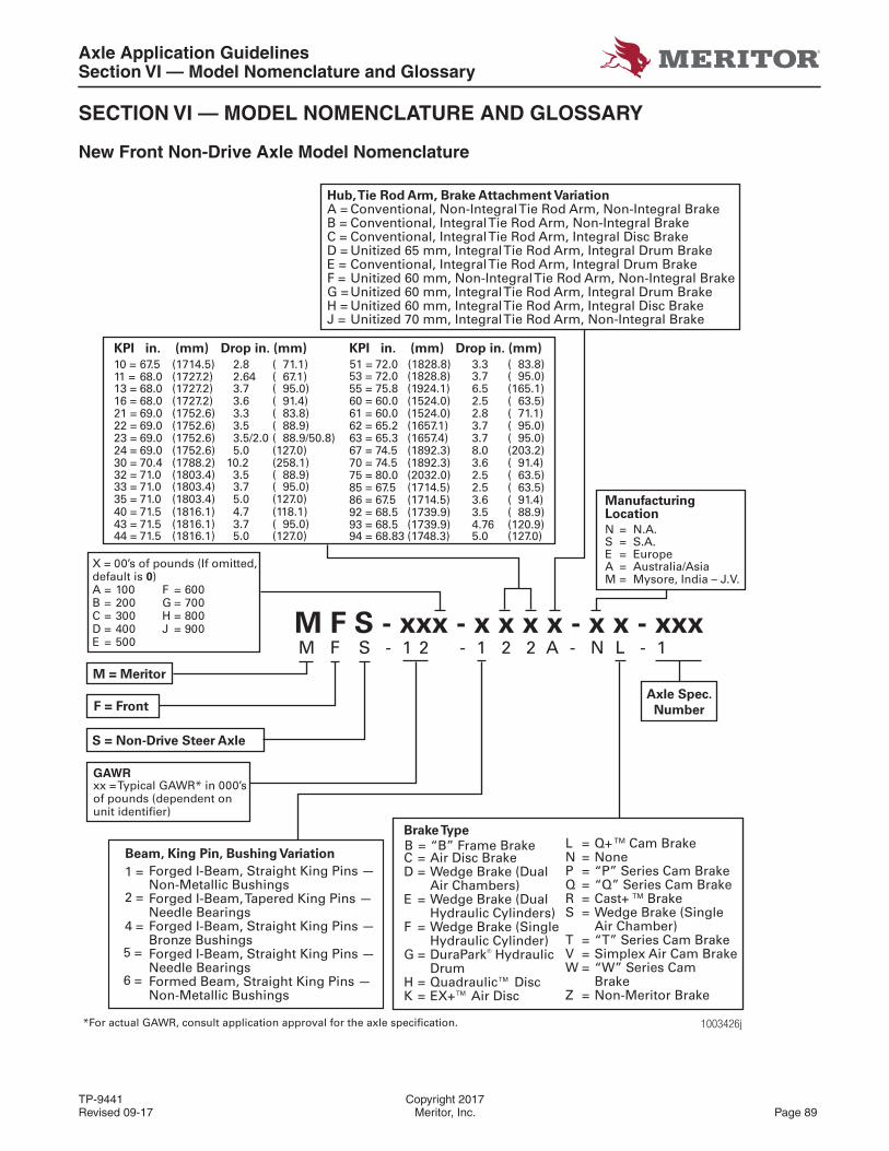
Axle Application GuidelinesSection VI — Model Nomenclature and Glossary
TP-9441 Copyright 2017Revised 09-17 Meritor, Inc. Page 89
SECTION VI — MODEL NOMENCLATURE AND GLOSSARY
New Front Non-Drive Axle Model Nomenclature
1003426j
M F S - 1 2 - 1 2 2 A - N L - 1 M F S - xxx - x x x x - x x - xxx
Beam, King Pin, Bushing Variation
Forged I-Beam, Straight King Pins — Non-Metallic BushingsForged I-Beam, Tapered King Pins — Needle BearingsForged I-Beam, Straight King Pins — Bronze BushingsForged I-Beam, Straight King Pins —Needle BearingsFormed Beam, Straight King Pins — Non-Metallic Bushings
1 =
2 =
4 =
5 =
6 =
KPI in. (mm) Drop in. (mm)
13 = 68.0 (1727.2) 3.7 ( 95.0)16 = 68.0 (1727.2) 3.6 ( 91.4)
10 = 67.5 (1714.5) 2.8 ( 71.1)11 = 68.0 (1727.2) 2.64 ( 67.1)
21 = 69.0 (1752.6) 3.3 ( 83.8)22 = 69.0 (1752.6) 3.5 ( 88.9)23 = 69.0 (1752.6) 3.5/2.0 ( 88.9/50.8)24 = 69.0 (1752.6) 5.0 (127.0)30 = 70.4 (1788.2) 10.2 (258.1)32 = 71.0 (1803.4) 3.5 ( 88.9)33 = 71.0 (1803.4) 3.7 ( 95.0)
40 = 71.5 (1816.1) 4.7 (118.1)35 = 71.0 (1803.4) 5.0 (127.0)
43 = 71.5 (1816.1) 3.7 ( 95.0)44 = 71.5 (1816.1) 5.0 (127.0)
51 = 72.0 (1828.8) 3.3 ( 83.8)
M = Meritor
F = Front
S = Non-Drive Steer Axle
Manufacturing Location
N = N.A.S = S.A.E = EuropeA = Australia/AsiaM = Mysore, India – J.V.
Axle Spec.
Number
Brake Type
C = Air Disc BrakeD = Wedge Brake (Dual
Air Chambers)E = Wedge Brake (Dual
Hydraulic Cylinders)F = Wedge Brake (Single
Hydraulic Cylinder)G = DuraPark® Hydraulic
DrumH = Quadraulic™ DiscK = EX+™ Air Disc
Hub, Tie Rod Arm, Brake Attachment VariationA = Conventional, Non-Integral Tie Rod Arm, Non-Integral BrakeB = Conventional, Integral Tie Rod Arm, Non-Integral BrakeC = Conventional, Integral Tie Rod Arm, Integral Disc BrakeD = Unitized 65 mm, Integral Tie Rod Arm, Integral Drum BrakeE = Conventional, Integral Tie Rod Arm, Integral Drum BrakeF = Unitized 60 mm, Non-Integral Tie Rod Arm, Non-Integral BrakeG =Unitized 60 mm, Integral Tie Rod Arm, Integral Drum BrakeH = Unitized 60 mm, Integral Tie Rod Arm, Integral Disc BrakeJ = Unitized 70 mm, Integral Tie Rod Arm, Non-Integral Brake
L = Q+ TM Cam BrakeN = NoneP = “P” Series Cam BrakeQ = “Q” Series Cam BrakeR = Cast+ TM BrakeS = Wedge Brake (Single
Air Chamber)T = “T” Series Cam BrakeV = Simplex Air Cam BrakeW = “W” Series Cam
BrakeZ = Non-Meritor Brake
B = “B” Frame Brake
KPI in. (mm) Drop in. (mm)
53 = 72.0 (1828.8) 3.7 ( 95.0)55 = 75.8 (1924.1) 6.5 (165.1)60 = 60.0 (1524.0) 2.5 ( 63.5)61 = 60.0 (1524.0) 2.8 ( 71.1)62 = 65.2 (1657.1) 3.7 ( 95.0)63 = 65.3 (1657.4) 3.7 ( 95.0)67 = 74.5 (1892.3) 8.0 (203.2)70 = 74.5 (1892.3) 3.6 ( 91.4)75 = 80.0 (2032.0) 2.5 ( 63.5)85 = 67.5 (1714.5) 2.5 ( 63.5)86 = 67.5 (1714.5) 3.6 ( 91.4)92 = 68.5 (1739.9) 3.5 ( 88.9)93 = 68.5 (1739.9) 4.76 (120.9)94 = 68.83 (1748.3) 5.0 (127.0)
*For actual GAWR, consult application approval for the axle specification.
GAWRxx = Typical GAWR* in 000’s of pounds (dependent on unit identifier)
X = 00’s of pounds (If omitted, default is 0)A = 100 F = 600B = 200 G = 700C = 300 H = 800D = 400 J = 900E = 500
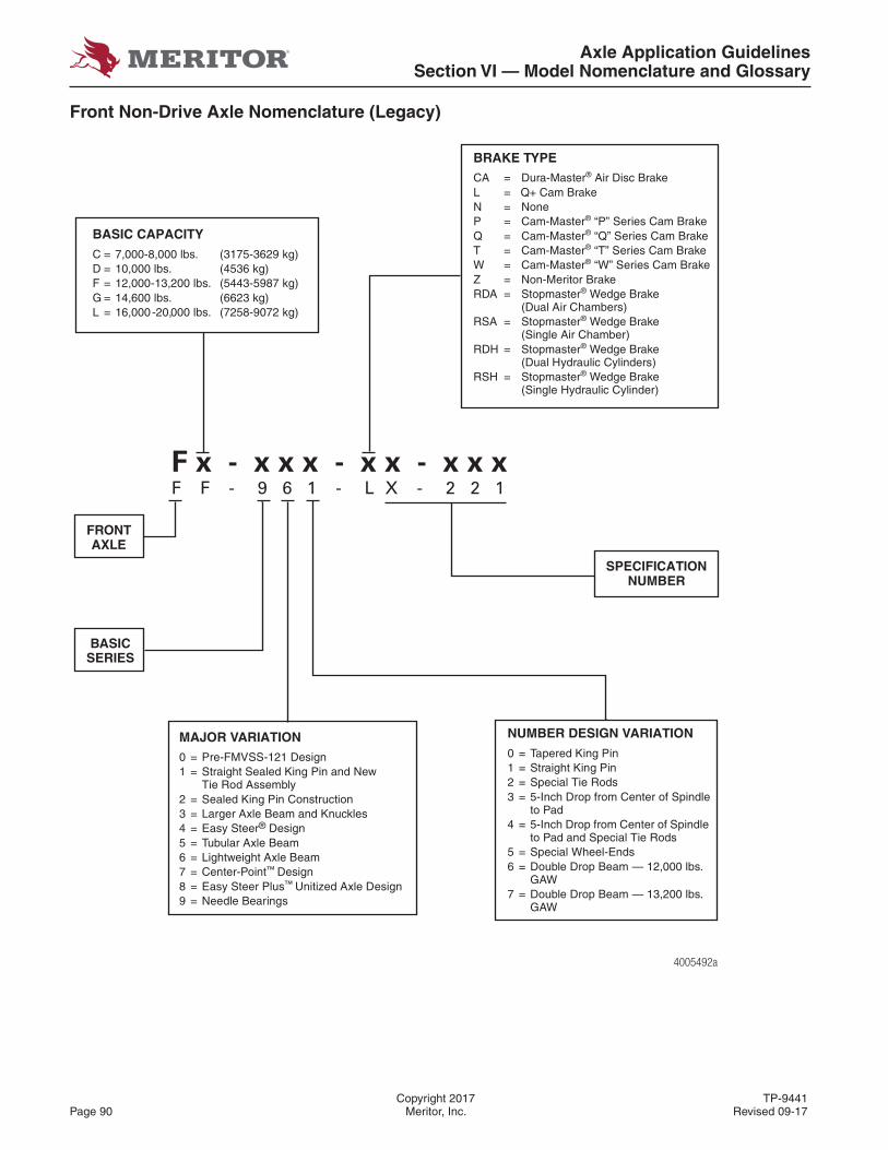
Axle Application GuidelinesSection VI — Model Nomenclature and Glossary
Copyright 2017 TP-9441Page 90 Meritor, Inc. Revised 09-17
Front Non-Drive Axle Nomenclature (Legacy)
4005492a
-05
BASIC CAPACITY
C = 7,000-8,000 lbs. (3175-3629 kg)D = 10,000 lbs. (4536 kg)F = 12,000-13,200 lbs. (5443-5987 kg)G = 14,600 lbs. (6623 kg)L = 16,000-20,000 lbs. (7258-9072 kg)
FRONTAXLE
MAJOR VARIATION0 = Pre-FMVSS-121 Design1 = Straight Sealed King Pin and New
Tie Rod Assembly2 = Sealed King Pin Construction3 = Larger Axle Beam and Knuckles4 = Easy Steer® Design5 = Tubular Axle Beam6 = Lightweight Axle Beam7 = Center-Point™ Design8 = Easy Steer Plus™ Unitized Axle Design9 = Needle Bearings
NUMBER DESIGN VARIATION
0 = Tapered King Pin1 = Straight King Pin2 = Special Tie Rods3 = 5-Inch Drop from Center of Spindle
to Pad4 = 5-Inch Drop from Center of Spindle
to Pad and Special Tie Rods5 = Special Wheel-Ends6 = Double Drop Beam — 12,000 lbs.
GAW7 = Double Drop Beam — 13,200 lbs.
GAW
SPECIFICATION NUMBER
BRAKE TYPECA = Dura-Master® Air Disc BrakeL = Q+ Cam BrakeN = NoneP = Cam-Master® “P” Series Cam BrakeQ = Cam-Master® “Q” Series Cam BrakeT = Cam-Master® “T” Series Cam Brake W = Cam-Master® “W” Series Cam BrakeZ = Non-Meritor BrakeRDA = Stopmaster® Wedge Brake
(Dual Air Chambers)RSA = Stopmaster® Wedge Brake
(Single Air Chamber)RDH = Stopmaster® Wedge Brake
(Dual Hydraulic Cylinders)RSH = Stopmaster® Wedge Brake
(Single Hydraulic Cylinder)
BASIC SERIES
F F - 9 6 1 - L X - 2 2 1F x - x x x - x x - x x x
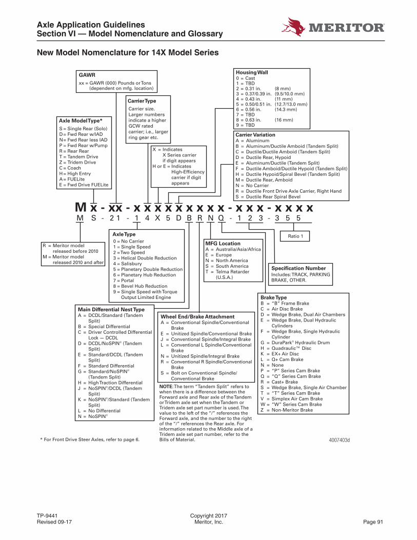
Axle Application GuidelinesSection VI — Model Nomenclature and Glossary
TP-9441 Copyright 2017Revised 09-17 Meritor, Inc. Page 91
New Model Nomenclature for 14X Model Series
4007403d
M x - xx - x x x x x x x x x - x x x - x x x x
Housing Wall0 = Cast1 = TBD2 = 0.31 in. (8 mm)3 = 0.37/0.39 in. (9.5/10.0 mm)4 = 0.43 in. (11 mm)5 = 0.50/0.51 in. (12.7/13.0 mm)6 = 0.56 in. (14.3 mm)7 = TBD8 = 0.63 in. (16 mm)9 = TBD
Carrier Type
GAWR
xx = GAWR (000) Pounds or Tons (dependent on mfg. location)
Axle Model Type*
R = Meritor modelreleased before 2010
M = Meritor modelreleased 2010 and after
* For Front Drive Steer Axles, refer to page 6.
X = IndicatesX Series carrierif digit appears
H or E = Indicates High-Efficiency carrier if digit appears
Specification Number
Includes: TRACK, PARKINGBRAKE, OTHER.
Ratio 1Axle Type
0 = No Carrier1 = Single Speed2 = Two Speed3 = Helical Double Reduction4 = Salisbury5 = Planetary Double Reduction6 = Planetary Hub Reduction7 = Portal8 = Bevel Hub Reduction9 = Single Speed with Torque Output Limited Engine
M S - 2 1 - 1 4 X 5 D B R N Q - 1 2 3 - 3 5 5
Carrier VariationA = Aluminum B = Aluminum/Ductile Amboid (Tandem Split)C = Ductile/Ductile Amboid (Tandem Split) D = Ductile Rear, HypoidE = Aluminum/Ductile (Tandem Split) F = Ductile Amboid/Ductile Hypoid (Tandem Split)H = Ductile Hypoid/Spiral Bevel (Tandem Split)M = Ductile Rear, AmboidN = No CarrierR = Ductile Front Drive Axle Carrier, Right HandS = Ductile Rear Spiral Bevel
MFG LocationA = Australia/Asia/AfricaE = Europe N = North America S = South AmericaT = Telma Retarder (U.S.A.)
Brake TypeB = “B” Frame BrakeC = Air Disc BrakeD = Wedge Brake, Dual Air ChambersE = Wedge Brake, Dual Hydraulic CylindersF = Wedge Brake, Single Hydraulic CylinderG = DuraPark® Hydraulic DrumH = Quadraulic™ DiscK = EX+ Air DiscL = Q+ Cam BrakeN = NoneP = “P” Series Cam BrakeQ = “Q” Series Cam BrakeR = Cast+ BrakeS = Wedge Brake, Single Air ChamberT = “T” Series Cam BrakeV = Simplex Air Cam BrakeW = “W” Series Cam BrakeZ = Non-Meritor Brake
Main Differential Nest TypeA = DCDL/Standard (Tandem Split)B = Special DifferentialC = Driver Controlled Differential Lock — DCDLD = DCDL/NoSPIN® (Tandem Split)E = Standard/DCDL (Tandem Split)F = Standard DifferentialG = Standard/NoSPIN® (Tandem Split)H = High Traction DifferentialJ = NoSPIN®/DCDL (Tandem Split)K = NoSPIN®/Standard (Tandem Split)L = No DifferentialN = NoSPIN®
Wheel End/Brake AttachmentA = Conventional Spindle/Conventional Brake E = Unitized Spindle/Conventional BrakeJ = Conventional Spindle/Integral BrakeL = Conventional L Spindle/Conventional Brake N = Unitized Spindle/Integral BrakeR = Conventional R Spindle/Conventional Brake S = Bolt on Conventional Spindle/ Conventional Brake
NOTE: The term “Tandem Split” refers to when there is a difference between theForward axle and Rear axle of the Tandemor Tridem axle set when the Tandem orTridem axle set part number is used. Thevalue to the left of the “/” references theForward axle, and the number to the rightof the “/” references the Rear axle. Forinformation related to the Middle axle of aTridem axle set part number, refer to theBills of Material.
Carrier size. Larger numbers indicate a higher GCW rated carrier; i.e., larger ring gear etc.
S = Single Rear (Solo)D = Fwd Rear w/IADN = Fwd Rear less IADP = Fwd Rear w/PumpR = Rear RearT = Tandem DriveZ = Tridem DriveC = CoachH = High EntryA = FUELiteE = Fwd Drive FUELite
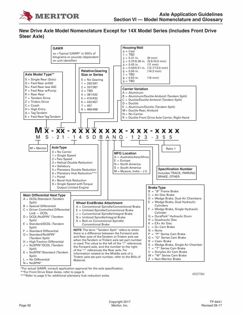
Axle Application GuidelinesSection VI — Model Nomenclature and Glossary
Copyright 2017 TP-9441Page 92 Meritor, Inc. Revised 09-17
New Drive Axle Model Nomenclature Except for 14X Model Series (Includes Front Drive Steer Axle)
M x - xx - x x x x x x x x - x x x - x x x x
M = Meritor
Specification NumberIncludes: TRACK, PARKINGBRAKE, OTHER.
*For actual GAWR, consult application approval for the axle specification.**For Front Drive Steer Axles, refer to page 6.***Refer to page 5 for additional planetary hub reduction axles.
GAWRxx = Typical GAWR* in 000’s of kilograms or pounds (dependenton unit identifier)
Axle Model Type**S = Single Rear (Solo)D = Fwd Rear w/IADN = Fwd Rear less IADP = Fwd Rear w/PumpR = Rear RearT = Tandem DriveZ = Tridem DriveC = CoachHA = Tag TandemE = Fwd Rear Tag Tandem
= High Entry
Relative Gearing Size or Series0 = No Gearing1 = 292/3472 = 337/3873 = TBD4 = 381/4325 = 415/4326 = 432/4577 = 4578 = 460/498
Housing Wall0 = Cast1 = TBD2 = 0.31 in. (8 mm)3 = 0.37/0.39 in. (9.5/10.0 mm)4 = 0.43 in. (11 mm)5 = 0.50/0.51 in. (12.7/13.0 mm)6 = 0.56 in. (14.3 mm)7 = TBD8 = 0.63 in. (16 mm)9 = TBD
Ratio 1Axle Type0 = No Carrier1 = Single Speed2 = Two Speed3 = Helical Double Reduction4 = Salisbury5 = Planetary Double Reduction6 = Planetary Hub Reduction***7 = Portal8 = Bevel Hub Reduction9 = Single Speed with Torque Output Limited Engine
4002706d
M S - 2 1 - 1 4 5 D B A N Q - 1 2 3 - 3 5 5
Main Differential Nest TypeA = DCDL/Standard (Tandem Split)B = Special DifferentialC = Driver Controlled Differential Lock — DCDLD = DCDL/NoSPIN® (Tandem Split)E = Standard/DCDL (Tandem Split)F = Standard DifferentialG = Standard/NoSPIN® (Tandem Split)H = High Traction DifferentialJ = NoSPIN®/DCDL (Tandem Split)K = NoSPIN®/Standard (Tandem Split)L = No DifferentialN = NoSPIN®
Wheel End/Brake AttachmentA = Conventional Spindle/Conventional Brake E = Unitized Spindle/Conventional BrakeJ = Conventional Spindle/Integral Brake N = Unitized Spindle/Integral Brake S = Bolt on Conventional Spindle/ Conventional Brake
Carrier VariationA = Aluminum B = Aluminum/Ductile Amboid (Tandem Split)C = Ductile/Ductile Amboid (Tandem Split) D = Ductile E = Aluminum/Ductile (Tandem Split) M = Ductile Rear, AmboidN = No CarrierR = Ductile Front Drive Axle Carrier, Right Hand
MFG LocationA = Australia/Asia/AfricaE = Europe N = North America S = South AmericaM = Mysore, India – J.V.
Brake TypeB = “B” Frame BrakeC = Air Disc BrakeD = Wedge Brake, Dual Air ChambersE = Wedge Brake, Dual Hydraulic CylindersF = Wedge Brake, Single Hydraulic CylinderG = DuraPark® Hydraulic DrumH = Quadraulic DiscK = EX+ Air DiscL = Q+ Cam BrakeN = NoneP = “P” Series Cam BrakeQ = “Q” Series Cam BrakeR = Cast+ BrakeS = Wedge Brake, Single Air ChamberT = “T” Series Cam BrakeV = Simplex Air Cam BrakeW = “W” Series Cam BrakeZ = Non-Meritor Brake
NOTE: The term “Tandem Split” refers to when there is a difference between the Forward axle and Rear axle of the Tandem or Tridem axle set when the Tandem or Tridem axle set part number is used. The value to the left of the “/” references the Forward axle, and the number to the rightof the “/” references the Rear axle. For information related to the Middle axle of aTridem axle set part number, refer to the Bills of Material.
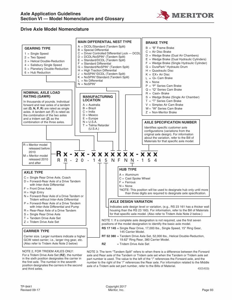
Axle Application GuidelinesSection VI — Model Nomenclature and Glossary
TP-9441 Copyright 2017Revised 09-17 Meritor, Inc. Page 93
Drive Axle Model Nomenclature
4005493b
NOTE 2, FOR TRIDEM AXLES ONLY:For a Tridem Drive Axle Set (RZ), the number in the sixth position designates the carrier in the first axle. The number in the seventh position designates the carriers in the second and third axles.
GEARING TYPE
1 = Single Speed2 = Two Speed3 = Helical Double-Reduction4 = Salisbury Single Speed5 = Planetary Double-Reduction6 = Hub Reduction
NOMINAL AXLE LOAD RATING (GAWR)In thousands of pounds. Individual forward and rear axles of a tandem set (D, N, P, R) are rated as single axles. A tandem set (T) is rated as the combination of the two axles and a tridem set (Z) as the combination of the three axles.
AXLE TYPEC = Single Rear Drive Axle, CoachD = Forward-Rear Axle of a Drive Tandem
with Inter-Axle DifferentialF = Front Drive AxleH = High EntryN = Forward-Rear Axle of a Drive Tandem or
Tridem without Inter-Axle DifferentialP = Forward-Rear Axle of a Drive Tandem
with Inter-Axle Differential and PumpR = Rear-Rear Axle of a Drive TandemS = Single Rear Drive AxleT = Tandem Drive Axle SetZ = Tridem Drive Axle Set
CARRIER TYPE
AXLE SPECIFICATION NUMBERIdentifies specific customer axle configurations (variations from the original axle design). For information about the variation, refer to the Bill of Materials for that specific axle model.
HUB TYPEA = AluminumC = Cast Spoke WheelF = FerrousN = None*NOTE: This position will be used to designate hub only until more
than three digits are required to designate axle specification.
AXLE DESIGN VARIATION
BRAKE TYPEB = “B” Frame BrakeC = Air Disc BrakeD = Wedge Brake (Dual Air Chambers)E = Wedge Brake (Dual Hydraulic Cylinders)F = Wedge Brake (Single Hydraulic Cylinder)G = DuraPark® Hydraulic Drum H = Quadraulic DiscK = EX+ Air Disc
Q+ Cam Brake
Cast+ Brake
L = N = NoneP = “P” Series Cam BrakeQ = “Q” Series Cam BrakeR =S = Wedge Brake (Single Air Chamber)T = “T” Series Cam BrakeV = Simplex Air Cam BrakeW = “W” Series Cam BrakeZ = Non-Meritor Brake
R R - 2 0 - 1 4 5 N F N N - 1 5 4R x - x x - x x x x x x x - x x x
MAIN DIFFERENTIAL NEST TYPEA = DCDL/Standard (Tandem Split)B = Special DifferentialC = Driver Controlled Differential Lock — DCDLD = DCDL/NoSPIN® (Tandem Split)E = Standard/DCDL (Tandem Split)F = Standard DifferentialG = Standard/NoSPIN® (Tandem Split)H = High Traction DifferentialJ = NoSPIN®/DCDL (Tandem Split)K = NoSPIN®/Standard (Tandem Split)L = No DifferentialN = NoSPIN®
MANUFACTURINGLOCATIONA = AustraliaB = BrazilC = IndiaD = MexicoE = EuropeN = U.S.A.T = Telma Retarder (U.S.A.)
NOTE 1: If a complete axle designation is not required, use the first seven positions of the model designation to identify the basic axle model.RS 17 145 = Single Rear Drive, 17,000 lbs., Single Speed, 15" Ring Gear, 145 Carrier Model.RT 52 380 = Tandem Drive Axle Set, 52,000 lbs., Helical Double-Reduction, 19.62" Ring Rear, 380 Carrier Model.RZ = Tridem Drive Axle Set
Indicates axle design level or variation, (e.g., RS 23 161 has a thicker wallhousing than the RS 23 160). For information, refer to the Bill of Materialsfor that specific axle model. (Also refer to Tridem Axle Note 2 below.)
Carrier size. Larger numbers indicate a higherGCW rated carrier; i.e., larger ring gear, etc. (Also refer to Tridem Axle Note 2 below)
NOTE 3: The term “Tandem Split” refers to when there is a difference between the Forward axle and Rear axle of the Tandem or Tridem axle set when the Tandem or Tridem axle set part number is used. The value to the left of the “/” references the Forward axle, and the number to the right of the “/” references the Rear axle. For information related to the Middle axle of a Tridem axle set part number, refer to the Bills of Material.
R = Meritor modelreleased before 2010
M = Meritor modelreleased 2010 and after
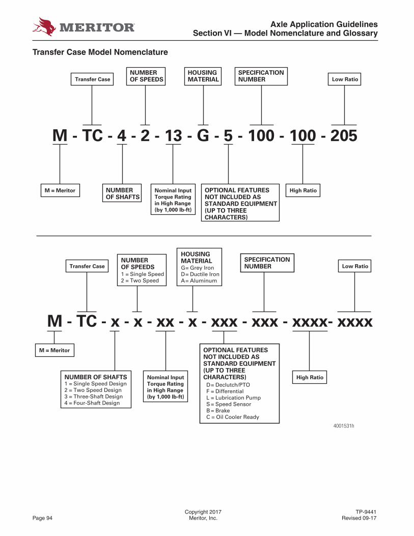
Axle Application GuidelinesSection VI — Model Nomenclature and Glossary
Copyright 2017 TP-9441Page 94 Meritor, Inc. Revised 09-17
Transfer Case Model Nomenclature
S
M = Meritor
NUMBER OF SHAFTS Nominal Input
Torque Rating
in High Range
(by 1,000 lb-ft)
OPTIONAL FEATURESNOT INCLUDED ASSTANDARD EQUIPMENT(UP TO THREECHARACTERS) High Ratio
Transfer CaseNUMBEROF SPEEDS
HOUSINGMATERIAL SPECIFICATION
NUMBER Low Ratio
1 = Single Speed2 = Two Speed
G= Grey IronD= Ductile IronA= Aluminum
1 = Single Speed Design2 = Two Speed Design3 = Three-Shaft Design4 = Four-Shaft Design
M - TC - 4 - 2 - 13 - G - 5 - 100 - 100 - 205
M = Meritor NUMBEROF SHAFTS
Nominal Input
Torque Rating
in High Range
(by 1,000 lb-ft)
OPTIONAL FEATURESNOT INCLUDED ASSTANDARD EQUIPMENT(UP TO THREECHARACTERS)
High Ratio
Transfer Case
NUMBEROF SPEEDS
HOUSINGMATERIAL
SPECIFICATIONNUMBER Low Ratio
M - TC - x - x - xx - x - xxx - xxx - xxxx- xxxx
D= Declutch/PTOF = DifferentialL = Lubrication PumpS = Speed SensorB = BrakeC = Oil Cooler Ready
4001531h
Axle Application GuidelinesSection VI — Model Nomenclature and Glossary
TP-9441 Copyright 2017Revised 09-17 Meritor, Inc. Page 95
Glossary
Active Suspension – While conventional suspension uses springs and shock absorbers to isolate the vehicle from the bouncing movement of the wheels when it contacts rough roads, active suspension uses power actuators that are controlled by a computer. These actuators place the wheels of the vehicle in the best position to accommodate rough roads as well as compensate for different load levels
Air Over/Under – In relation to suspensions.
Overslung – Suspension arm goes above or over the axle air bag.
Underslung – Suspension arm goes below or under the axle air bag.
Alternative Drive System – A system that uses pure electric energy or two or more distinct sources of energy for propulsion (e.g., electric/gasoline, hydraulic). This can increase the stress on the axle components, reducing the life of the axle.
Amboid Gear – Modifi ed Spiral Bevel Gear that allows the pinion to be positioned above the ring gear centerline.
Auxiliary Axle (Pusher or Tag) – An extra axle kept in a lifted position and only dropped to the pavement when its extra load carrying capacity is needed. Pushers are located in front of the drive axle, and tags are located behind the drive axle. Both can also be steerable.
Auxiliary Transmission – Additional gear box that increases the gear ratio combinations when used with the main transmission or multi-speed axles.
Axle Shift System – The actual control mechanism that is employed to control movement of a shift fork or sliding clutch to vary the axle ratio.
Beam Drop – Distance from the Brake Shoe centerline to the Brake Chamber centerline.
Bearing Shoulder to Bearing Shoulder Dimension – Distance from the machined inner bearing contact point on one side of the axle to the other machined inner bearing contact point on the other side.
Bogie – A combination of two axles usually pivoting about a common trunnion.
Combination – Truck coupled to one or more trailers.
DCDL (Driver-Controlled Differential Lock) – Driver-controlled traction device that can be operated from the vehicle cab by a switch. A mechanism that eliminates the action of the differential so that both wheels can be driven to improve tractive efforts on slippery surfaces.
Dolly – Two-wheel trailer equipped with drawbar and the lower portion of a fi fth wheel and other components necessary to permit a semi trailer and dolly combination to operate a full trailer; sometimes called a “PUP”.
Double Drop – Beam having a drop in the center between the spring mounting pads as well as the drop from the KPI to the spring mounting pads.
Double Reduction – Dual gear reduction generally used in rear axles.
Drive Input to Carrier –
DIRDL - Drive Input Rear Down LeftDIRUR - Drive Input Rear Up RightDIRUL - Drive Input Rear Up LeftDIRDR - Drive Input Rear Down Right
Dual Torque Engines (e.g., 1550/1750) – Engines having two torque curves: a high torque curve available in the higher numeric transmission ratios and a lower torque for lower numeric transmission ratios. The Engine Control Unit (ECU) manages these changes.
Engine Brake – A system that allows for slowing of a vehicle that is independent of the conventional braking systems.
GAW (Gross Axle Weight) – Total weight on a specifi c axle position.
GAWR (Gross Axle Weight Rating) – The total weight capacity of an axle (single, tandem, or tridem).
GCW (Gross Combination Weight) – The total weight of a truck and trailer combination and its entire contents.
GCWR (Gross Combination Weight Rating) – The total weight capacity of a truck and trailer combination and its entire contents as determined by axle ratings.
Gear Ratio – Ratio of the speed of the propeller shaft to the speed of the rear axle shaft.
Grade – The degree of inclination of a road, typically specifi ed in percent.
GVW (Gross Vehicle Weight) – The total weight capacity of a single vehicle.
GVWR (Gross Vehicle Weight Rating) – The total weight capacity of a single vehicle as determined by axle ratings or frame limitations.
Horsepower – English unit used to denote the amount of work done in a given period of time, equal to 33,000 foot-pounds per minute.
Housing – A casing or container for mechanical components.
Axle Application GuidelinesSection VI — Model Nomenclature and Glossary
Copyright 2017 TP-9441Page 96 Meritor, Inc. Revised 09-17
Housing Box, Rectangular Section – Cross section of square-armed or rectangular-armed housing.
HWT (Housing Wall Thickness) – Nominal housing wall thickness at the box section.
IAD (Inter-Axle Differential) – Gear device dividing power equally between axles and compensating for unequal tire diameters.
Integral Knuckle – One piece steel knuckle forging made with both steer and tie rod arms forged into one piece.
Jake Brake – Trademark of engine brakes by the Vehicle Equipment Division of The Jacobs Manufacturing Co. See “Engine Brake”.
KPI (Kingpin Intersection) – The distance between the intersection points of LH and RH steer knuckles pivot, or the points where the spindle axis crosses the king pin axis.
Limited-slip Differential – Mechanical action that resists the free working of an ordinary differential, thus distributing a greater torque to the slower turning wheel or axle.
LL or L – Transmission gears designed to be used as “Creeper” or “Crawler” for vehicle positioning and speed control.
Mechanical Suspensions – A suspension that is not an air ride suspension.
Michigan Special Gravel Trains – An eleven axle combination permitted in Michigan with gross weights as high as 164,000 lbs.
NoSPIN® – Speed sensitive automatic locking differential. It powers both drive wheels while automatically permitting differential action to compensate for wheel speed differences from turning or driving on uneven surfaces.
Job Site Travel Rate (Creep Rate) – Extremely slow operation (< 5 mph) when the vehicle is loaded and the auxiliary axle is lifted.
Outset Wheel – Wheel with a centerline of the tire outboard of the wheel mounting surface.
Parallelogram Suspension – A suspension with four trailing arms that allow the axle to travel in a linear motion without caster change.
Regional Haul (Hub and Spoke) – On-highway (8% maximum grade) hauling goods within a region, typically a one day round trip.
Retarder – Auxiliary speed-reducing device.
Roll-Off Containers – Detachable open containers generally used for hauling refuse, scrap, and construction debris and are hoisted or winched over the rear of the truck chassis for transport.
Semi-trailer – Trailer used in connection with a truck tractor.
Single Reduction – Any axle assembly with only one gear reduction through its differential ring gear and drive pinion.
Site Travel – Slow speed operation up to 5 mph at a job site; not to exceed 5% of total operation miles of the vehicle.
Slip Torque – Engine torque required to slip wheels on the driving surface.
SLR (Static Loaded Radius) – The distance from the centerline of axle to the ground, under rated tire capacity, with the tire at rest.
SMC (Suspension Mounting Centers) – The distance between the suspension bracket mounting centers on the axle.
Soft Dampened Clutch – Special type of clutch that features a torsional mechanism that avoids impact loads being transmitted through the driveline.
STD Track (Standard Track) – The distance between the dual centerlines on a dual tire arrangement, or the distance between the tire centerlines on a single tire arrangement.
Steering Knuckle (Conventional) – Loose tie rod arm and steering arm
Straight Truck – A non-articulated vehicle that carries cargo in a body mounted to its chassis, rather than on a trailer towed by the vehicle.
Super Single Tire – Specially designed tire used in lieu of dual tires in certain applications. Can reduce maintenance and/or save weight compared to duals.
Tandem Axles – Two-axle drive combination or dual drive axles.
Tandem Split – Refers to when there is a difference between the forward axle carrier and the rear axle carrier of the Tandem or Tridem axle set when the Tandem or Tridem axle set part number is used. The fi rst character references the forward axle, and the second references the rear axle. For information related to the middle axle of a Tridem axle set, refer to the Bill of Materials. (e.g., one axle has a DCDL, and the other axle has a standard differential)
Torque Converter – A hydraulic drive that transmits power with ability to change torque.
Axle Application GuidelinesSection VI — Model Nomenclature and Glossary
TP-9441 Copyright 2017Revised 09-17 Meritor, Inc. Page 97
Track – The distance between the dual tire centerlines on a dual tire arrangement or the distance between the tire centerlines on a single tire arrangement.
Tractor – Truck portion of combination or train.
Tridem Axles – A combination of three axles having a common suspension.
Truck – Straight truck with no trailer attached.
Two-speed Axle – A rear-axle assembly that has two different output ratios from the differential carrier assembly.
Vocation – Specifi c usage of a vehicle in a defi ned industry.
VRD (Vehicle Retarder Device) – Auxiliary speed-reducing device including engine, transmission, exhaust, chassis and focally mounted.
Walking Beam Suspension – A mechanical suspension that attaches two axles together with the use of a leaf spring or structural beam that pivots about a trunnion tube.
Wheelbase – Distance between centerlines of front steer and rear drive axles or to centerline of tandem axles.
Wheel Inset, Negative – The rim centerline is positioned inboard of the wheel mounting face.
Wheel Inset, Positive – The rim centerline is positioned outboard of the wheel mounting face.
Wide Track – Extended length housing used to meet increased track and stability requirements.
Meritor Heavy Vehicle Systems, LLC2135 West Maple RoadTroy, MI 48084 USA866-OnTrac1 (668-7221)meritor.com
Information contained in this publication was in effect at the time the publication was approved for printing and is subject tochange without notice or liability. Meritor Heavy Vehicle Systems, LLC, reserves the right to revise the information presented orto discontinue the production of parts described at any time.
Copyright 2017Meritor, Inc.All Rights Reserved
TP-9441Revised 09-17
(16579)Printed in USA