Embed Size (px)
Citation preview

TP3 LNCaldera de alto rendimiento para combustibles líquidos o gaseososCaldaia ad alto rendimento per combustibili liquidi o gassosiHigh-efficiency boiler for liquid or gas fuelsChaudière à haut rendement pour les combustibles liquides ou gazeuxСтальной котел высокой производительности, работающий на жидком или газообразном топливе
ES INSTRUCCIONES PARA EL USO, LA INSTALACIÓN Y EL MONTAJEIT ISTRUZIONI PER L’USO, L’INSTALLAZIONE E IL MONTAGGIOEN INSTRUCTIONS FOR USE, INSTALLATION AND ASSEMBLYFR INSTRUCTIONS D’UTILISATION, D’INSTALLATION ET DE MONTAGERU ТЕХНИЧЕСКИЙ ПАСПОРТ ИЗДЕЛИЯ
РУКОВОДСТВО ПО ЭКСПЛУАТАЦИИ, МОНТАЖУ ИТЕХОБСЛУЖИВАНИЮ
cod.
354
5458
/0 -
10/2
019
HHH

2 ES
TP3 LN
cod. 3545458/0 - 10/2019
1. PRESENTACION .......................................................................................................................................................................... 32. Advertencias generales .............................................................................................................................................................. 33. Certificaciones ............................................................................................................................................................................ 34. Característicastécnicas,constructivasydimensionales ....................................................................................................... 34.1 Descripción del aparato ................................................................................................................................................................................. 3
4.2 Principio de funcionamiento ........................................................................................................................................................................... 4
4.3 Datos técnicos - Medidas - Conexiones hidráulicas ...................................................................................................................................... 5
4.4 Identificación .................................................................................................................................................................................................. 6
5. Instalación ................................................................................................................................................................................... 65.1 Embalaje ........................................................................................................................................................................................................ 6
5.2 Manipulación .................................................................................................................................................................................................. 6
5.3 Local de instalación (Fig. 5) ........................................................................................................................................................................... 7
5.4 Evacuación de los productos de combustión (Fig. 6) .................................................................................................................................... 8
5.5 Conexiones hidráulicas .................................................................................................................................................................................. 8
5.5.1 Agua de alimentación ............................................................................................................................................................................... 8
5.5.2 Tuberías de ida/retorno instalación .......................................................................................................................................................... 8
5.5.3 Tuberías de llenado/vaciado instalación .................................................................................................................................................. 9
5.5.4 Tuberías vaso de expansión y válvula de seguridad ............................................................................................................................... 9
5.5.5 Bomba de recirculación (Fig. 7) ............................................................................................................................................................... 9
5.6 Puerta anterior apertura y regulación ............................................................................................................................................................ 9
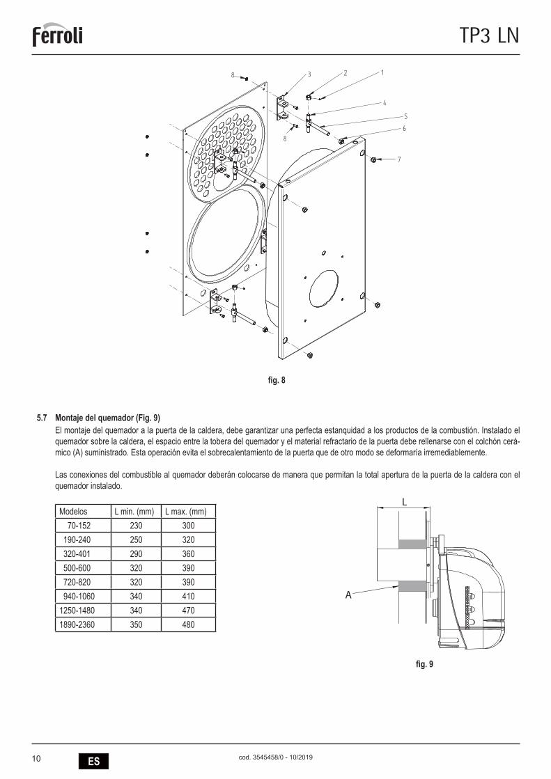
5.7 Montaje del quemador (Fig. 9) ..................................................................................................................................................................... 10
5.8 Conexión piloto control llama (Fig. 10) .........................................................................................................................................................11
5.9 Montaje revestimiento de paneles mod. 92÷190 ..........................................................................................................................................11
5.10 Montaje revestimiento de paneles mod. 240÷2360 ..................................................................................................................................... 12
6. Puestaenmarcha ..................................................................................................................................................................... 136.1 Controles preliminares ................................................................................................................................................................................. 13
6.2 Primer encendido ......................................................................................................................................................................................... 13
6.3 Apagado de la caldera ................................................................................................................................................................................. 13
7. Mantenimiento ........................................................................................................................................................................... 137.1 Disposiciones generales .............................................................................................................................................................................. 13
7.2 Mantenimiento ordinario .............................................................................................................................................................................. 13
7.3 Mantenimiento extraordinario ...................................................................................................................................................................... 14
7.4 Limpieza de la caldera ................................................................................................................................................................................. 14
7.5 Verificación del funcionamiento de la caldera .............................................................................................................................................. 14
7.6 Verificación del funcionamiento del quemador ............................................................................................................................................ 15
7.7 Problemas y soluciones posibles ................................................................................................................................................................. 15

3ES
TP3 LN
cod. 3545458/0 - 10/2019
1. PRESENTACIONEstimado cliente,Le damos las gracias por haber elegido una caldera TP3 LN. Este manual se ha elaborado para informarle, con advertencias y consejos, sobre la instalación, uso correcto y mantenimiento de la caldera.Le rogamos que lo lea atentamente y lo guarde para consultas posteriores. Por su propio interés le invitamos a seguir y observar atentamente las instrucciones que se dan en el presente manual para poder disfrutar plenamente de este producto de alta calidad. El incumplimiento y la no observación de cuanto figura en el presente manual exoneran a la empresa fabricante de cualquier responsabilidad e invalidan la garantía.
2. ADVERTENCIAS GENERALES - El manual de instrucciones forma parte del producto y proporciona una descripción de todo aquello que se debe observar en la fase de - instalación, uso y mantenimiento. - Este aparato debe destinarse sólo al uso para el que ha sido expresamente previsto. - Esteaparatosirveparacalentaraguaaunatemperaturainferioraladeebulliciónalapresiónatmosféricaydebeunirseaunainstalacióndecalefaccióny/oaunainstalacióndedistribucióndeaguacalienteparausosanitario,deacuerdoconsuscaracte-rísticasyprestacionesyalapotenciacalorífica.
- Antes de la instalación debe comprobarse que la caldera no haya sufrido ningún daño derivado de la manipulación y el transporte. - La caldera debe instalarse sobre una base no inflamable. - La caldera debe instalarse a una distancia de al menos 100 mm de cualquier material o componente inflamable. - La instalación debe ser realizada por personal debidamente cualificado y de acuerdo con las normas vigentes. - Antes de realizar cualquier operación de limpieza o de mantenimiento, desenchufe el aparato de la red de suministro eléctrico. - EL FABRICANTE no responde de los daños ocasionados a personas y/o a cosas debidos a errores en la instalación, de regulación, de
mantenimiento y a usos incorrectos. - La puesta en marcha de la caldera y de la correspondiente instalación debe ser realizada por una persona autorizada. - La primera puesta en marcha tiene por objetivo verificar el buen funcionamiento de todos los dispositivos de regulación y de control. - La no utilización del aparato durante un largo período de tiempo requiere la intervención de personal cualificado.
NormativasEl instalador debe respetar la reglamentación local y vigente en cuanto corresponde a: la elección del lugar de instalación de la caldera, el respeto de las condiciones de ventilación necesarias, que la conexión y la chimenea se encuentren en perfectas condiciones, las conexiones del combustible, de las instalaciones eléctricas y otras disposiciones eventuales por cuanto respecta a la seguridad.CondicionesdegarantíaLa validez de la garantía está subordinada a la observación de las normas y consejos de uso contenidos en el presente manual. Cualquier incumpli-mientoomodificaciónlaharánula.Lagarantíanocubrelosdañosocasionadosporlacorosióndecondensadoácidodelosproductosdelacombustiónodebidosalaformacióndeincrustacionescausadasporelusodeaguasdurasoagresivas,yaquesólosonimputablesalaexplotacióndelainstalación.
3. CERTIFICACIONES
ElmarcadoCEacreditaquelosproductoscumplenlosrequisitosfundamentalesdelreglamentoGARyotrasdirectivasaplicables.Ladeclaracióndeconformidadpuedesolicitarsealfabricante.
CÓDIGOS DE IDENTIFICACIÓN DE LOS PRODUCTOSTP3 LN 70 ORD099XA TP3 LN 320 ORD600XA TP3 LN 940 ORDG00XATP3 LN 92 ORD000XA TP3 LN 401 ORD800XA TP3 LN 1060 ORDH00XATP3 LN 107 ORD100XA TP3 LN 500 ORDB00XA TP3 LN 1250 ORDJ00XATP3 LN 152 ORD200XA TP3 LN 600 ORDD00XA TP3 LN 1480 ORDL00XATP3 LN 190 ORD300XA TP3 LN 720 ORDE00XA TP3 LN 1890 ORDP00XATP3 LN 240 ORD400XA TP3 LN 820 ORDF00XA TP3 LN 2360 ORDS00XA
PAÍSES DE DESTINO: ES - IT - FR - RU
4. CARACTERÍSTICAS TÉCNICAS, CONSTRUCTIVAS Y DIMENSIONALES4.1 Descripcióndelaparato
El tipo de construcción de las calderas de la serie TP3 LN garantiza potencia y elevados rendimientos con bajas temperaturas de humos, obte-niéndose así escasas emisiones contaminantes. La fabricación sigue la norma EN 303 parte 1. Los principales elementos técnicos del diseño son:- el cuidadoso estudio de las geometrías, para obtener una relación óptima entre los volúmenes de combustión y las superficies de intercambio- la elección de los materiales usados, para una larga duración de la caldera.Las calderas son de combustión presurizada, con 3 pasos de humos efectivos, con doble revestimiento estanco superpuesto con el hogar completamente rodeado por el agua que lo enfría en la parte inferior y el haz tubular en la parte superior, en los que se insertan los turbohélices que crean un recorrido vertiginoso que aumenta el intercambio térmico por convección. A la salida del haz tubular los humos se recogen en la cámara posterior y se encauzan hacia la chimenea.

4 ES
TP3 LN
cod. 3545458/0 - 10/2019
Las calderas están equipadas con una puerta con bisagra para su apertura hacia la derecha o hacia la izquierda y regulable en altura y profundi-dad. El revestimiento estanco del cuerpo está aislado mediante un grueso colchón de lana de vidrio recubierto con una capa posterior de material antiroturas. El acabado externo está formado por paneles de acero barnizado. Los ganchos de elevación se hallan en la parte superior del reves-timiento estanco. Las calderas están provistas de 2 conexiones de 1/2” para vainas porta bulbos (aptas para alojar 3 bulbos cada una). El panel de mando (encargar por separado) que ya está precableado se colocará sobre la caldera y permite el funcionamiento automático de la misma.
4.2 PrincipiodefuncionamientoLas calderas TP3 LN están provistas de un hogar cilíndrico ciego completamente rodeado por el agua que lo enfría en el que se desarrolla el primer paso de humos, un tubo de hogar de retorno de gran diámetro (2º paso) y un haz tubular situado en la parte superior (3er paso). A la sali-da del haz tubular los humos se recogen en la cámara de humos posterior y desde aquí se envían a la chimenea. Durante el funcionamiento del quemador la cámara de combustión siempre está a presión. Para el conocer el valor de esta presión vea la tabla de la Pág. 36, en la columna Pérdidas de carga lado humos. El conducto de humos y la conexión a la chimenea deben realizarse de acuerdo con las Normas y la Legisla-ción vigente, con conductos rígidos, resistentes a la temperatura, el agua de condensación, los esfuerzos mecánicos y la estanquidad (Fig. 1).
Leyenda1 Cuadro de mandos T2 Retorno calefacción2 Brida conexión quemador T3 Conexión vaso de expansión3 Puerta de limpieza de la cámara de humos T4 Descarga caldera4 Mirilla control llama T5 Conexión chimeneaT1 Entrada calefacción T6 Conexión quemador
3
T3T1T2
T4
T5
F B E
P
L1 R
I
T1-T3-T2
A
Q
CD
H
T6
1
T1-T3-T2
T4
T5
2
4
LG
M
0694
ModelloModel
230V - ~50 Hz
Elektrisk forsyning
Alimentazione elettricaElectrical InputAlimantation éléctriqueAlimentaciòn eléctrìca
ktrnhjgbnfybt
StromspannungStroomspanningAlimentacao elèctricaIngaende spanning
Potenza termica Nominale
l
cod. 313
50491
Nominal Power Output
Portata Termica NominaleNominal Power Input
kW
kW
Max Pressure Heatingbar
Max Temp. RiscaldamentoMax Temp Heating
°C
Max Press. Riscaldamento
No. MatricolaConstruction No.
Konstruktions-nr.Herstellnr.
NennwarmeleistungNominal warmtevermogen
NennheizwertNominaal verwarmingsvermogen
Max. WasserdruckMax. waterdruk
Max. KesseltemperaturMax. Ketelstemperatuur
Fabrikaatnr.No.de fabricationNo de construccaoValmistusnumeroPfdjlcrjq yjvthNo.de fabricacion
Dèbito tèrmico nominalDèbit thermique nominalNominell varmetillforselCaudal tèrmico nominal NtgkjghjbpdjlbntkmyjcnmNominel termisk forsyning
Puissance nominal Potencia NominalPotencia Nominal Nomineel effektNominel Kraft Gjktpyfz Ntgkjdfzvjoyjcnm
Pression maxi Chauffage Pressao màx. de caldeiraPresiòn màx. de Calefacciòn Max tryckVarmeanlaegets maks.-tryk Vfrc= hf,jxtt lfdktybt
Temperature maxi Chauffage Temperatura màx. de caldeiraTemper.màx.de Calefacciòn Max varmartemperaturVarmeanlaegets maks.-temperatur Vfrc= hf,jxfz ntvgthfnehf
H O
Codice PinCode
t.max safety 114°C
bar
Pressione prova idraul./DataHidraulic test pressure/DatePre ssi on d'é pre uve hy dra uli que /Da tePrueba presiòn hidràulica/FechaDruck wasserdruckprÜfung/Datum
Vandtrykprøve/DatoWaterdrukproef/DatumPressÃo do teste hidràulico/DataHydrauliskt testtryck/DatumJghtccjdjxyjt lfdkt ybt #Lfnf
VIA RI TON DA 78/ A - 37 047 SA N B ONI FACIO - V R - IT ALY
Vjltkm
Rjl
J,mtv rjnkjdjq djls
'
354
5051/1
MANDATADEPARTVORLAUFFLOWAANVOER
RITORNORETOURRUCKLAUFRETURN
3540
907/2
3540
908/2
ATTENZIONE35451110
ATTENTION
Prima di accendere il bruciatoreassicurarsi della tenuta del portelloneonde evitare di rovinare la guarnizione. Per la regolazione e l'apertura del portellone vedere libretto istruzioni.
Before firing the burner please check the gas-side tightness onto the ceramic fiber rope of the front door. For door hinges adjustment see instruction book.
ACHTUN G - Ei n mogl icher Splat zwisch en Bre nnerro hr und fe uerfes ter au skleidung is t mit kerami kfaser es Sei l ab zuschl iessen .
OPGELE T - De mogel ijke spleet tussen brand erpijp en br anderp laat m et hittebest endig koord afluit en.
ATTENT ION - L'inte rstice event uel en tre la tete du bru leur et le re veteme nt refactair e doit etre rempli par u n co rdon e n fibr e ceramique.
ATTENZ IONE - Chiud ere con un c ordone di fi bra ce ramica l' eventu ale fe ssura tra il canot to del bruci atore e il fo ro esi stente sulla porta .
CAUTIO N - Th e even tual gap bet ween b urner head a nd re fracto ry lin ing must be sealed by a cerami c fibe r ro pe.
cod.35450482
ON
fig.2
fig.1

5ES
TP3 LN
cod. 3545458/0 - 10/2019
4.3 Datostécnicos-Medidas-Conexioneshidráulicas
TP3 LN 70 92 107 152 190 240 320 401 500
Potencianominalmin. kW 46 60 70 100 137 160 196 260 341max. kW 70 92 107 152 190 240 320 401 500
Potenciadelhogarmin. kW 48 62,7 73,2 104,7 143,8 167,8 205,2 271,5 354,6max. kW 73,9 97,1 112,9 160,5 200,8 252,9 335,7 419,4 522,8
Pérdidasdecargaladoagua Dt 15ºC mbar 6 6 12 7 10 17 23 22 28Pérdidasdecargaladohumos mbar 0,54 0,89 1,2 1,65 1,8 2,4 3,3 4,4 5,43Caudalhumos* kg/h 119 156 182 258 321 405 539 670 838Presiónmáximadeejercicio** bar 6 6 6 6 6 6 6 6 6Pesoensecoestándar6bar kg 236 236 332 332 460 524 833 833 1146
MEDIDAS
A mm 670 670 670 670 760 760 820 820 855B mm 770 770 1190 1190 1190 1390 1590 1590 1990C mm 1116 1116 1116 1116 1271 1271 1456 1456 1546D mm 165 165 165 165 165 165 165 165 165E mm 146 146 146 146 165 165 184 184 184F mm 152 152 152 152 152 152 152 152 152G mm 880 880 880 880 985 985 1140 1140 1225H mm 390 390 390 390 420 420 460 460 480I mm 1130 1130 1555 1555 1570 1770 1990 1990 2390M mm 160 160 160 160 145 145 160 160 155
CONEXIONES
entrada T1 2” 1/2 2” 1/2 2” 1/2 2” 1/2 2” 1/2 2” 1/2 DN 80 DN 80 DN 100retorno T1 2” 1/2 2” 1/2 2” 1/2 2” 1/2 2” 1/2 2” 1/2 DN 80 DN 80 DN 100seguridad T3 1” 1/2 1” 1/2 1” 1/2 1” 1/2 1” 1/2 1” 1/2 DN 50 DN 50 DN 65descarga T4 3/4” 3/4” 3/4” 3/4” 3/4” 3/4” 3/4” 3/4” 3/4”salida humo T5 Ø mm 160 160 160 160 220 220 250 250 300conexión quemador T6 Ø mm 145 145 145 150 150 150 240 240 240lg. mín./máx. tobera T6 250/320 250/320 250/320 250/320 250/320 250/320 250/320 290/360 290/360
TP3 LN 600 720 820 940 1060 1250 1480 1890 2360
Potencianominalmin. kW 390 468 533 611 689 813 962 1229 1535max. kW 600 720 820 940 1060 1250 1480 1890 2360
Potenciadelhogarmin. kW 403,8 484,8 552,3 633,4 714,5 843,7 999,1 1278,1 1598,9max. kW 627,2 752,5 856,7 981,6 1106,3 1303,6 1542,0 1919,3 2449,8
Pérdidasdecargaladoagua Dt 15ºC mbar 18 25 25 33 40 55 45 70 65Pérdidasdecargaladohumos mbar 6,2 5,9 6,7 6,3 7,2 7 7,4 7,2 7,8Caudalhumos* kg/h 1005 1207 1376 1574 1774 2088 2474 3091 3947Presiónmáximadeejercicio** bar 6 6 6 6 6 6 6 6 6Pesoensecoestándar6bar kg 1146 1557 1584 2329 2329 2601 2871 3552 4041
MEDIDAS
A mm 855 990 990 1150 1150 1180 1180 1340 1340B mm 1990 1944 1944 2394 2394 2594 2894 2698 2998C mm 1546 1791 1791 2021 2021 2021 2021 2371 2371D mm 165 165 165 165 165 165 165 165 165E mm 184 184 184 206 206 206 206 206 206F mm 152 212 212 212 212 212 212 212 212G mm 1225 1395 1395 1625 1625 1605 1605 1920 1920H mm 480 530 530 600 600 575 575 670 670I mm 2390 2410 2410 2880 2880 3080 3380 3180 3480M mm 1615 1860 1860 2100 2100 2100 2100 2440 2440
CONEXIONES
entrada T1 DN 100 DN 125 DN 125 DN 150 DN 150 DN 150 DN 150 DN 200 DN 200retorno T1 DN 100 DN 125 DN 125 DN 150 DN 150 DN 150 DN 150 DN 200 DN 200seguridad T3 DN 65 DN 80 DN 80 DN 100 DN 100 DN 100 DN 100 DN 125 DN 125descarga T4 3/4” 3/4” 3/4” 1” 1/2 1” 1/2 1” 1/2 1” 1/2 1” 1/2 1” 1/2salida humo T5 Ø mm 300 350 350 400 400 450 450 500 500conexión quemador T6 Ø mm 210 210 270 270 270 270 350 350 350lg. mín./máx. tobera T6 320/390 320/390 320/390 320/390 340/410 340/410 340/410 340/470 350/480
* Combustible gasóleo: CO2 = 13% - Combustible gas: CO2 = 10%

6 ES
TP3 LN
cod. 3545458/0 - 10/2019
4.4 Identificación La caldera se puede identificar mediante:-Sobreportadocumentos(1) Está pegado a la puerta y contiene: MANUAL TÉCNICO CERTIFICADO DE GARANTÍA ETIQUETAS CON CÓDIGO DE BARRAS PLACA TÉCNICA CERTIFICADO DE FABRICACIÓN (que atestigua el buen resultado de la prueba hidráulica)
-Placatécnica(2) En la placa técnica figuran los datos técnicos y las prestaciones del aparato (Fig. 3). Se halla en el sobre portadocumentos y, una vez finalizada la instalación, el instalador DEBE COLOCARLA OBLIGATORIAMENTE en la parte anterior superior de uno de los paneles laterales de la carcasa, de modo visible. En caso de pérdida pedir un duplicado al Servicio técnico de asistencia Ferroli.
La alteración, retirada, falta de placas de identificación o todo aquello que no permita la identificación segura del producto, dificulta las operaciones de instalación y mantenimiento.
5. INSTALACIÓN5.1 Embalaje
Las calderas TP3 LN se entregan con: puerta, cámara de humos montada e aislamiento en el cuerpo, mientras que el revestimiento se halla en un embalaje de cartón (fig. 2). El panel de instrumentos se entrega en una caja de cartón situada en la cámara de combustión. Las calderas RSH modelo 1600-2600 se entregan con aislamiento y carcasa. El panel de instrumentos (accesorio que debe encargarse aparte) se entrega en una caja de cartón y se sitúa en la cámara de combustión.
5.2 ManipulaciónLas calderas TP3 LN están provistas de cáncamo de elevación. Realizar la manipulación con precaución mediante instrumentos adecuados para su peso. Antes de colocar la caldera retire la base de madera desatornillando los tornillos de fijación (Fig. 4).
fig.3
1
2
0694
ModelloModel
230V - ~50 Hz
Elektrisk forsyning
Alimentazione elettricaElectrical InputAlimantation éléctriqueAlimentaciòn eléctrìca
StromspannungStroomspanningAlimentacao elèctricaIngaende spanning
Potenza termica Nominale
l
cod. 31350491
Nominal Power Output
Portata Termica NominaleNominal Power Input
kW
kW
Max Pressure Heatingbar
Max Temp. RiscaldamentoMax Temp Heating
°C
Max Press. Riscaldamento
No. MatricolaConstruction No.
Konstruktions-nr.Herstellnr.
NennwarmeleistungNominal warmtevermogen
NennheizwertNominaal verwarmingsvermogen
Max. WasserdruckMax. waterdruk
Max. KesseltemperaturMax. Ketelstemperatuur
Fabrikaatnr.No.de fabricationNo de construccaoValmistusnumero
No.de fabricacion
Dèbito tèrmico nominalDèbit thermique nominalNominell varmetillforselCaudal tèrmico nominal
Nominel termisk forsyning
Puissance nominal Potencia NominalPotencia Nominal Nomineel effektNominel Kraft
Pression maxi Chauffage Pressao màx. de caldeiraPresiòn màx. de Calefacciòn Max tryckVarmeanlaegets maks.-tryk
Temperature maxi Chauffage Temperatura màx. de caldeiraTemper.màx.de Calefacciòn Max varmartemperaturVarmeanlaegets maks.-temperatur
H O
Codice PinCode
t.max safety 114°C
bar
Pressione prova idraul./DataHidraulic test pressure/DatePression d'épreuve hydraulique/DatePrueba presiòn hidràulica/FechaDruck wasserdruckprÜfung/Datum
Vandtrykprøve/DatoWaterdrukproef/DatumPressÃo do teste hidràulico/DataHydrauliskt testtryck/Datum
VIA RITONDA 78/A - 37047 SAN BONIFACIO - VR - ITALY
Заводской номер
Теплопроизводительность
Полезная Тепловаямошность
Макс. рабочее давление
Макс. рабочее температура
Обьем котловой воды
Опрессовочное давление/Дата
Электропитание
Код
Модель
2
1
fig.4

7ES
TP3 LN
cod. 3545458/0 - 10/2019
5.3 Localdeinstalación(Fig.5)Las calderas TP3 LN se instalarán en locales para su uso exclusivo, que respondan a las Normas técnicas y a la Legislación vigente y provistos de aperturas de ventilación de medidas adecuadas. La aperturas de ventilación deberán ser permanentes, comunicando directamente con el exterior y situadas a nivel alto y bajo de acuerdo con las normativas vigentes. La ubicación de las aperturas de ventilación, los circuitos de suministro del combustible, de distribución de la energía eléctrica y de iluminación deberán respetar las disposiciones legales vigentes en rela-ción con el tipo de combustible empleado. Para facilitar la limpieza del circuito de humos, en la parte anterior de la caldera, deberá dejarse un espacio libre igual o mayor que la longitud del cuerpo de la caldera y, en ningún caso inferior a 1.300 mm y deberá verificarse que con la puerta abierta a 90º la distancia entre la puerta y la pared adyacente (X), sea como mínimo igual a la longitud del quemador. El plano de apoyo de la caldera deberá ser totalmente horizontal. Se recomienda prever un zócalo de cemento, llano, capaz de soportar el peso total de la caldera más el contenido de agua. Para las medidas del zócalo, véase las cotas R x Q (tabla de medidas). En caso de que el quemador sea alimentado con gas combustible de peso específico superior al del aire, las partes eléctricas deberán situarse a una distancia de tierra superior a los 500 mm. El aparato no se puede instalar al aire libre porque no está diseñado para funcionar en el exterior y no dispone de sistemas antihielo automáticos.
COLOCACIÓN EN INSTALACIONES VIEJAS O POR REMODELARCuando se coloque la caldera en instalaciones antiguas o por remodelar, verifique que:
- La chimenea sea adecuada para las temperaturas de los productos de la combustión, que esté calculada y construida de acuerdo con la normativa vigente, que sea estanca, aislada y que no haya oclusiones o angosturas.
- La instalación eléctrica se haya realizado de acuerdo con las Normas vigentes y por personal cualificado. - La línea de suministro del combustible y el eventual depósito se hayan realizado de acuerdo con las normas vigentes. - El/los vaso/s de expansión aseguran la total absorción de la dilatación del fluido contenido en la instalación. - El caudal, la presión estática y la dirección del flujo de las bombas de circulación sean adecuados. - La instalación esté lavada, limpia de fangos, incrustaciones, eliminado el aire y que se hayan verificado las estanquidades. - Se haya previsto un sistema de tratamiento del agua de alimentación/reabastecimiento (véase valores de referencia).
600
600
1000
X
1000
fig.5

8 ES
TP3 LN
cod. 3545458/0 - 10/2019
5.4 Evacuacióndelosproductosdecombustión(Fig.6)El conducto de humos y la conexión a la chimenea deben realizarse de acuerdo con las Normas y la Legislación vigente, con conductos rígidos, resistentes a la tempe-ratura, el agua de condensación, los esfuerzos mecánicos y la estanquidad. La chi-menea debe asegurar la presión negativa mínima prevista por las normas vigentes, considerando como presión “cero” la conexión con el conducto de humos. La chime-nea y los conductos de humos inadecuados o mal dimensionados pueden ampliar el ruido de la combustión, generar problemas de condensación e influir negativamente en los parámetros de combustión. Los conductos de evacuación no aislados son una fuente de peligro potencial. La estanquidad de las uniones se realizará con materia-les resistentes a temperaturas de cómo mínimo 250ºC. En el tramo de unión entre la caldera y la chimenea, se tienen que prever puntos adecuados de medición de la temperatura de los humos y el análisis de los productos de la combustión. En cuanto a la sección y la altura de la chimenea, debe hacerse referencia a las reglamentacio-nes nacionales y locales en vigor.
ATENCIÓN: debido a la baja temperatura de los humos puede producirse condensa-ción dentro de la chimenea.
5.5 Conexioneshidráulicas5.5.1 Aguadealimentación
Las características químicas del agua de la instalación y de reabastecimiento, son fundamentales para el buen funcionamiento y la seguridad de la caldera; se aplica-rán al agua los oportunos sistemas de tratamiento. Como valores de referencia se pueden considerar los que figuran en la tabla.
DUREZA TOTAL ppm 10ALCALINIDAD mg/l CaCO3 750PH 8÷9SÍLICE ppm 100CLORUROS ppm 3500
Es absolutamente indispensable el tratamiento del agua usada para la instalación de calefacción en los siguientes casos:- Instalaciones muy extendidas.- Agua muy dura.- Frecuentes introducciones de agua de reabastecimiento en la instalación.
En caso de que fuera necesario el vaciado parcial o total de la instalación, se recomienda realizar el sucesivo llenado con agua tratada. Para el control del volumen de los reabastecimientos, se aconseja instalar un contador sobre la tubería. Los fenómenos más comunes que se producen en las instalaciones térmicas son:
- Incrustaciones de cal La cal se concentra en los puntos donde la temperatura de la pared es mayor. Las incrustaciones de cal, debido a su baja conductividad
térmica, reducen el intercambio térmico incluso en caso de la presencia de pocos milímetros, impiden el intercambio térmico entre los humos y el agua, comportando un aumento de la temperatura de las partes expuestas a la llama y las consiguientes rupturas (hendiduras) en la placa tubular.
- Corrosión lado agua La corrosión de las superficies metálicas de la caldera lado agua se debe al paso del hierro a solución mediante sus iones. En este proceso
tiene gran importancia la presencia de gases disueltos y en particular del oxígeno y del anhídrido carbónico. En presencia de aguas ablan-dadas y/o desmineralizadas, se estará libre del fenómeno de incrustación, pero no sucede lo mismo con las corrosiones. En este caso es necesario condicionar el agua con inhibidores de los procesos corrosivos.
5.5.2 Tuberíasdedescarga/regresoinstalaciónLas medidas de las tuberías de descarga y retorno están indicadas para cada modelo de caldera en la tabla MEDIDAS. Asegúrese en la instalación que haya un número suficiente de respiraderos. Las conexiones de la caldera no deben soportar el peso de las tuberías de unión a la instalación, por lo tanto deberá instalar los soportes adecuados.
fig.6

9ES
TP3 LN
cod. 3545458/0 - 10/2019
5.5.3 Tuberíasdellenado/descargainstalaciónPara el llenado y la descarga de la caldera se puede conectar un grifo a la conexión T4 que está en la parte posterior (véase diseño MEDIDAS).
5.5.4 TuberíasvasodeexpansiónyválvuladeseguridadLas calderas TP3 LN son aptas para funcionar con circulación de agua forzada con vaso de expansión tanto abierto como cerrado. Un vaso de expansión siempre es necesario, para compensar el aumento de volumen del agua debido al calentamiento. En el primer caso, la altura de la columna hidrostática deberá ser igual al menos a 3 metros por encima de la carcasa de la caldera y deberá tener una capaci-dad tal que contenga, entre la superficie libre del agua en el vaso y el tubo del rebosadero, el aumento del volumen de toda el agua de la instalación. Son preferibles vasos altos y estrechos de modo que se exponga al contacto con el aire la menor superficie de agua posible, reduciéndose así la evaporación. En el segundo caso, la capacidad del vaso de expansión cerrado se debe calcular teniendo en cuenta: - el volumen total del agua contenida en la instalación- la presión máxima de ejercicio de la instalación- la presión máxima de ejercicio del vaso de expansión- la presión de precarga inicial del vaso de expansión.La tubería de expansión une el vaso de expansión con la instalación. Esta tubería que partirá de la conexión T3 (véase tabla Medidas) no deberá tener ninguna válvula de corte. Instale en la conexión T3 o en la tubería de descarga a 0,5 m de la brida de partida, una válvula de seguridad adecuada para la capacidad de la caldera que cumpla las normativas locales en vigor. Se prohíbe interponer cualquier tipo de interceptación entre la caldera y las válvulas de seguridad, y se recomienda que dichas válvulas estén ajustadas para intervenir cuando se supere la presión máxima de ejercicio permitida.
5.5.5 Bombaderecirculación(Fig.7)La condensación del vapor de agua contenida en los humos de evacuación de la calde-ra (agua de condensación) se presenta cuando la temperatura del agua de retorno es inferior a 55ºC y es considerable sobretodo cuando se enciende por la mañana después que la caldera ha permanecido apagada durante toda la noche. El agua de condensa-ción es ácida y corrosiva, y con el tiempo ataca las chapas de la caldera. Es por lo tanto deseable la adopción de una bomba de recirculación, con una función de anticondensa-ción, instalada entre las conexiones de descarga y de retorno, por encima de la eventual válvula mezcladora. La bomba debe asegurar, durante los períodos de funcionamiento de la instalación, un caudal incluido entre el 20 y el 30% del total, debe garantizar una temperatura del agua de retorno igual o mayor que 55ºC, mientras que la presión estática requerida es modesta ya que sólo debe superar la resistencia de la caldera y la de las válvulas. Para obtener la temperatura de retorno de la instalación a fin de dirigir la bomba anticondensación o para manejar las funciones de puesta en régimen en sistemas de termorregulación, es necesario disponer un sumidero portasonda a una distancia equiva-lente a 3÷5 diámetros del tubo de retorno por encima del punto de empalme hidráulico.
5.6 PuertaanterioraperturayregulaciónPara los modelos TP3 LN el encaje en las bisagras, la fijación y la inversión de la abertura de la puerta se realizan de acuerdo con la fig. 8. Para ello es necesario realizar las siguientes operaciones:- La puerta se entrega con cuatro abrazaderas (pos. 3) y bisagras iguales.- Para establecer el sentido de abertura DERECHA o IZQUIERDA desatornille la tuerca (pos. 7), desatornille y retire la tuerca (pos. 6)
DCHA o IZQDA, así obtendremos el lado de abertura de la puerta. - La regulación en altura de la puerta se realiza mediante la tuerca (pos. 2); una vez finalizada la regulación, bloquear los tornillos prisio-
neros (pos. 1).- La regulación longitudinal se realiza mediante el tornillo (pos. 8).
Pie (Fig. 8)1 Espiga de fijación2 Tuerca de sostén/regulación puerta3 Abrazadera bisagra4 Perno bisagra5 Tornillo bisagra6 Tuerca de fijación bisagra7 Tuerca de fijación8 Tornillos y tuercas de fijación/regulación
fig.7
10 ES
TP3 LN
cod. 3545458/0 - 10/2019
5.7 Montajedelquemador(Fig.9)El montaje del quemador a la puerta de la caldera, debe garantizar una perfecta estanquidad a los productos de la combustión. Instalado el quemador sobre la caldera, el espacio entre la tobera del quemador y el material refractario de la puerta debe rellenarse con el colchón cerá-mico (A) suministrado. Esta operación evita el sobrecalentamiento de la puerta que de otro modo se deformaría irremediablemente.
Las conexiones del combustible al quemador deberán colocarse de manera que permitan la total apertura de la puerta de la caldera con el quemador instalado.
Modelos L min. (mm) L max. (mm) 70-152 230 300 190-240 250 320 320-401 290 360 500-600 320 390 720-820 320 390 940-1060 340 4101250-1480 340 4701890-2360 350 480
123
5
6
7
8
8
4
fig.8
L
A
fig.9

11ES
TP3 LN
cod. 3545458/0 - 10/2019
5.8 Conexiónpilotocontrolllama(Fig.10)El piloto de control de la llama está provisto de una toma de presión 1 que debe conectarse mediante un tubo de silicona o de cobre a la toma situada sobre el quemador 2. Esta operación permite al aire soplado por el ventilador enfriar el vidrio del piloto e impedir su ennegrecimiento. La no conexión del tubo al piloto puede ocasionar la ruptura del cristal de control.Para los grupos térmicos Ferroli, existen distintas configuraciones posibles respecto a lo anteriormente indicado, al haberse desarrollado cada unión en nuestra fábrica mediante pruebas de laboratorio específicas.
5.9 Montajedelrevestimientodepanelesmod.92-190Secuencia de montaje (Fig. 11)a) Colocar los paneles laterales derecho e izquierdo (pos. 1-2) enganchándolos al soporte (pos. 13). Para determinar cuál de los dos lados es
el derecho o el izquierdo, referirse al orificio para la placa pasacables (pos. 6), que debe hallarse en la parte delantera de la caldera.b) Fije el panel de mandos al panel superior (pos. 3).c) Apoye el panel superior derecho (pos. 3), que incluye el panel de mandos, al panel lateral (pos. 1) que incluye muelles, pernos de cierre y
tuercas (pos. 10-11-12).d) Inserte los bulbos de los instrumentos en las vainas como se indica en la fig. 20 y realice la conexión eléctrica del panel de mandos a la línea
de alimentación, al quemador y a las eventuales bombas, etc. Se recomienda insertar las sondas hasta el fondo de las correspondientes vainas para mejorar el contacto. Después bloquear los capilares con los muelles. Vuelva a cerrar la tapa del cuadro eléctrico, haga pasar el enchufe del quemador a través de la placa lateral (pos. 6) y bloquee el cable con el pasacables suministrado. Fije la placa (pos. 6) con los tornillos (pos. 7).
e) Monte el panel superior izquierdo (pos. 4) al panel lateral izquierdo (pos. 2) que incluye muelles, pernos de cierre y tuercas (pos. 10-11-12).f) Monte el panel posterior (pos. 8) a la caldera mediante los tornillos (pos. 13). g) Fije la placa de datos de la caldera, véase Cap. 1.4, después de haber limpiado y desengrasado con el disolvente adecuado la zona intere-
sada, y aplicarla adhiriéndola perfectamente. No retire la placa porque su adherencia disminuiría.
Laplacasehalladentrodelsobreportadocumentos.
2
1
fig.10
1
2
3
1310
67
10
11
13
12
4
11
12
8
13
fig.11

12 ES
TP3 LN
cod. 3545458/0 - 10/2019
5.10 Montajedelrevestimientodepanelesmod.240-2360Secuencia de montaje (Fig. 12)a) Coloque los paneles laterales (pos. 1-2 y 3-4) enganchándolos a los soportes (pos. 19).b) Coloque los paneles laterales superiores derechos (pos. 5-6) y luego los izquierdos (7-8) enganchándolos a los soportes de la caldera (pos.
19) y a la riostra (pos. 15).c) Fije el panel de mandos al panel superior derecho (pos. 5).d) Apoye el panel superior (pos. 5), que incluye el panel de mandos, al panel lateral (pos. 1) que incluye muelles, pernos de cierre y tuercas
(pos. 12-13-14).e) Inserte los bulbos de los instrumentos en las vainas como se indica en la fig. 19 y realice la conexión eléctrica del panel de mandos a la línea
de alimentación, al quemador y a las eventuales bombas, etc. Se recomienda insertar las sondas hasta el fondo de las correspondientes vainas para mejorar el contacto. Después bloquear los capilares con los muelles. Vuelva a cerrar la tapa del cuadro eléctrico, haga pasar el enchufe del quemador a través de la placa lateral (pos. 10) y bloquee el cable con el pasacables suministrado. Fije la placa (pos. 10) con los tornillos (pos. 11).
f) Monte el sostén (pos. 15).g) Monte los paneles superiores (pos. 5-6-7-8) enganchándolos a los paneles laterales (pos. 1-2-3-4) que incluye muelles, pernos de cierre y
tuercas (12-13-14).h) Fije la placa de datos de la caldera, véase Cap. 1.4, después de haber limpiado y desengrasado con el disolvente adecuado la zona intere-
sada, y aplicarla adhiriéndola perfectamente. No retire la placa porque su adherencia disminuiría.
Laplacasehalladentrodelsobreportadocumentos.
1
2
3
4
5
6
7
8
10
11
12
13
14
15
9 1119
fig.12

13ES
TP3 LN
cod. 3545458/0 - 10/2019
6. PUESTA EN MARCHA6.1 Controlespreliminares
- Realizadas las conexiones hidráulicas, eléctricas y del combustible a la caldera, antes de la puesta en marcha debe verificarse que: - El vaso de expansión y la válvula de seguridad estén correctamente conectados y no se puedan interceptar en modo alguno. - Los bulbos de los termostatos de regulación, de seguridad de mínima y del termómetro, estén introducidos en las respectivas vainas. - Los turbohélices se hallen situados en todos los tubos de humos. - La instalación esté llena de agua y sin nada de aire. - La bomba o las bombas funcionen correctamente. - Las conexiones hidráulicas, eléctricas y de seguridad necesarias y del combustible se hayan realizado de acuerdo con las disposiciones
nacionales y locales en vigor. - El quemador se haya montado de acuerdo con las instrucciones que figuran en el manual del fabricante. - El voltaje y la frecuencia de red sean compatibles con el quemador y el equipo eléctrico de la caldera. - La instalación sea capaz de absorber la cantidad de calor que se producirá. - La bomba de recirculación esté instalada como se describe en el apartado 5.5.5.
6.2 PrimerencendidoDespués de la salida positiva de las comprobaciones que se indican en el párrafo anterior, se podrá proceder al primer encendido del quemador que deberá ser realizada por un técnico en servicio y reconocido por la empresa fabricante del quemador. El técnico asumirá toda la respon-sa-bilidad en cuanto al campo de la regulación dentro del campo de potencia declarado y homologado de la caldera. Después de haber abierto los grifos de corte del combustible y controlado que no haya pérdidas en la red de suministro, poner todos los interruptores en la posición ON (conectado). El quemadorestá así preparado para el primer encendido y para la regulación que compete únicamente al técnico autorizado.Durante el primer encendido se deberá verificar que la puerta, la brida del quemador y las conexiones con la chimenea sean estancas y que la base de la chimenea tenga una ligera presión negativa. El caudal de combustible deberá corresponder a los datos de la tarjeta de la caldera y bajo ningún concepto deberá ser superior al valor máximo de la potencia nominal declarada. La temperatura de los humos nunca deberá ser inferior a 160ºC.
6.3 Apagadodelacaldera - Regular el termostato de ejercicio al mínimo. - Quitar tensión al quemador y cerrar la alimentación del combustible. - Dejar funcionar las bombas hasta que las cierre el termostato de mínima. - Quitar la tensión del cuadro eléctrico.
7. MANTENIMIENTO7.1 Disposicionesgenerales
El mantenimiento periódico es esencial para la seguridad, el rendimiento y la duración del aparato. Todas las operaciones deben ser realizadas por personal cualificado. Todas las operaciones de limpieza y mantenimiento deben ser precedidas por el cierre de la alimentación de combustible, tras desconectar la tensión eléctrica.Para obtener un buen funcionamiento y el máximo rendimiento de la caldera, es necesaria una limpieza regular de la cámara de combustión, de los tubos de humo y del humero.
7.2 MantenimientoordinarioEl mantenimiento debe establecerse en base al combustible usado, el número de encendidos, las características de la instalación, etc., por lo que no es posible establecer a priori un intervalo de tiempo entre un mantenimiento y el siguiente.Como principio aconsejamos los siguientes intervalos de limpieza según el combustible:
- Calderas de gas: un vez al año - Calderas de gasóleo: dos veces al año
En todos los casos se respetarán las eventuales normas locales respecto al mantenimiento.Durante las operaciones de mantenimiento ordinario, después de haber retirado los turbohélices se deberá limpiar con el escobillón el haz tubular y el hogar. Retirar los depósitos acumulados en la cámara de humos por la apertura de las puertas de inspección. En caso de acciones más enérgicas retirar la cámara de humos posterior y, si estuviera deteriorada, sustituir la junta de estanquidad de humos. Controlar que la evacuación del agua de condensación no esté obstruida. Se deberá comprobar el buen funcionamiento de los órganos de control y de medición del generador.En esta ocasión se deberá registrar la cantidad de agua de reabastecimiento usada, tras haber analizado el agua, realizar un desincrustación preventiva.Las sales de calcio y de magnesio disueltas en el agua ordinaria, con repetidos rellenados, da origen a depósitos en la caldera y provocan el sobrecalentamiento de las chapas con la posibilidad de que se produzcan daños que no se pueden atribuir ni a los materiales ni a la técnica de fabricación y que, por lo tanto, no están cubiertos por la garantía. Después de haber realizado las operaciones de mantenimiento y limpieza y el siguiente encendido, verificar la estanquidad de la puerta y de la cámara de humos, en caso de pérdidas del producto de la combustión, sustituir la junta de estanquidad correspondiente.Las operaciones realizadas se anotarán en el cuaderno de central.

14 ES
TP3 LN
cod. 3545458/0 - 10/2019
7.3 MantenimientoextraordinarioMantenimiento extraordinario de final de temporada o para largos períodos de inactividad.Se deben realizar todas las operaciones descritas en el capítulo precedente y además:
- Controlarelestadodedesgastedelosturbohélices. - Despuésdelalimpiarelcircuitodehumosesconvenientepasarunpañoempapadoconunasolucióndisueltadesosacáustica.Despuésdehaberdejadosecar,repasartodaslassuperficiesconunpañoempapadoenaceite.
- Serecomiendacolocardentrodelhogarsustanciashigroscópicas(calviva,silicogelenpequeñoscontenedores)ycerrarhermé-ticamentedemaneraquenoentreaire.
- Novaciarlainstalaciónnilacaldera. - Protegerconunamezcladeaceiteygrafitolostornillos,tuercasypernosdelapuerta.
Las operaciones realizadas se anotarán en el libro de registro de mantenimiento.7.4 Limpiezadelacaldera
Para realizar la limpieza proceder del siguiente modo: - La caldera viene con cepillo de limpieza para limpiar los tubos de humos. - Abrir la puerta anterior (1) y extraer las turbohelices (2). - Limpiar las superficies internas de la cámara de combustión y del recorrido de los humos usando un escobillón (3) u otro utensilio adecuado
para dicho fin. - Retirar los depósitos acumulados en la cámara de humos por la apertura de la tapa de limpieza (4). En caso de acciones más enérgicas
retirar la cámara de humos (5) sustituyendo la junta de estanquidad antes de realizar el montaje. - Controlar periódicamente que la evacuación del agua de condensación (6) no esté obstruida.
7.5 VerificacióndelfuncionamientodelacalderaAntes de efectuar el encendido y la prueba funcional de la caldera, comprobar que:
- Los turboladores estén colocados al tope con los tubos de intercambio. - Los grifos del circuito hidráulico y del combustible estén abiertos. - Haya combustible disponible. - El depósito de expansión esté adecuadamente cargado. - La presión en frío del circuito hidráulico sea superior a 1 bar e inferior al límite máximo previsto para la caldera. - Los circuitos hidráulicos estén purgados del aire. - Se hayan efectuado las conexiones eléctricas a la red de alimentación y a los componentes (quemador, bomba, cuadro de mando, ter-
mostatos, etc.). - La conexión fase-neutro se debe respetar en absoluto; la conexión de tierra es obligatoria.
Después de efectuar las operaciones antedichas, para poner la caldera en marcha es necesario:• Si la instalación tiene termorregulador o cronotermostatos, comprobar que estén en estado “activo”.• Ajustar los cronotermostatos ambiente o la termorregulación a la temperatura deseada.• Encender el interruptor general de la instalación.• Poner en “on” el termostato de la caldera situado en el cuadro de mando y verificar el encendido de la señal verde.
fig.13 fig.14
5
4
6
1
32
5
4
6
1
32

15ES
TP3 LN
cod. 3545458/0 - 10/2019
La caldera ejecuta la fase de encendido y permanece en funcionamiento hasta alcanzar las temperaturas programadas. Si se producen anoma-lías de encendido o de funcionamiento, la caldera efectúa una “PARADA DE BLOQUEO”, señalizada por el testigo rojo situado en el quemador y la indicación roja del cuadro de mando. Después de una “PARADA DE BLOQUEO” esperar aproximadamente 30 segundos para restablecer las condiciones de marcha. Para restablecer las condiciones de marcha, pulsar la “tecla/testigo” del quemador y esperar hasta que se encienda la llama. Si la llama no se enciende, la operación se puede repetir 2-3 veces como máximo; luego consultar:
- El manual de instrucciones del quemador. - El capítulo “VERIFICACIÓN DEL FUNCIONAMIENTO DE LA CALDERA”. - Las conexiones eléctricas en el esquema suministrado con el cuadro de mando.
Después de la puesta en marcha, comprobar que el aparato efectúe una parada y el siguiente reencendido: - Modificando la calibración del termostato de la caldera. - Accionando el interruptor principal del cuadro de mando. - Interviniendo en el termostato ambiente o en el programador horario o en la termorregulación. - Verificando la libre y correcta rotación de las bombas de circulación. - Verificando la parada total de la caldera al accionar el interruptor general de la instalación.
Si se cumplen todas las condiciones, poner en marcha el aparato, realizar un control de la combustión (análisis de los humos), del caudal de combustible y de la estanqueidad de las juntas de la puerta y de la cámara de humo.
7.6 Verificacióndelfuncionamientodelquemador- Consultar el manual de instrucciones del quemador.- Seguir todas las prescripciones de las normas locales en materia de mantenimiento del quemador.
7.7 ProblemasysolucionesposiblesA continuación se enumeran los principales problemas o anomalías que pueden ocurrir durante la gestión de la caldera, las causas posibles y las respectivas soluciones.
ANOMALÍAEL GENERADOR SE ENSUCIA FÁCILMENTECAUSA: Quemador mal regulado SOLUCIÓN: Controlar la regulación del quemador (análisis humos)
Chimenea obstruida Limpiar el recorrido de los humos y el humeroRecorrido del aire del quemador sucio Limpiar la bóveda de aire del quemador
EL GENERADOR NO CONSIGUE SUBIR LA TEMPERATURACAUSA: Cuerpo generador sucio SOLUCIÓN: Limpiar el recorrido de los humos
Combinación generador/quemador Controlar los datos y las regulacionesCaudal quemador insuficiente Controlar la regulación del quemadorTermostato de regulación Verificar el correcto funcionamiento
Verificar la temperatura programadaEL GENERADOR SE BLOQUEA POR SEGURIDAD TÉRMICA CON SEÑAL LUMINOSA EN EL CUADRO DE MANDOCAUSA: Termostato de regulación SOLUCIÓN: Verificar el correcto funcionamiento
Verificar la temperatura seleccionadaVerificar el cableado eléctricoVerificar bulbos sondas
Ausencia de agua Verificar la presión del circuitoPresencia de aire Verificar la válvula de purga
EL GENERADOR ESTÁ EN TEMPERATURA PERO EL SISTEMA DE CALENTAMIENTO ESTÁ FRÍOCAUSA: Aire en la instalación SOLUCIÓN: Purgar de aire la instalación
Bomba de circulación en avería Desbloquear la bomba de circulaciónTermostato de mínima (si lo hay) Verificar la temperatura seleccionada
OLOR DE PRODUCTOS NO QUEMADOSCAUSA: Dispersión de humos en el ambiente SOLUCIÓN: Verificar la limpieza del cuerpo del generador
Verificar la limpieza del conducto de humosVerificar el carácter hermético del generador, los conductos de humos y la chimenea
INTERVENCIÓN FRECUENTE DE LA VÁLVULA DE SEGURIDADCAUSA: Presión del circuito de la instalación SOLUCIÓN: Verificar la presión de carga
Verificar el circuito de la instalaciónVerificar la calibraciónVerificar la temperatura seleccionada
Vaso de exspansion de la instalación Verificar

16 IT
TP3 LN
cod. 3545458/0 - 10/2019
1. PRESENTAZIONE ...................................................................................................................................................................... 172. AVVERTENZE GENERALI ......................................................................................................................................................... 173. CERTIFICAZIONE ...................................................................................................................................................................... 174. CARATTERISTICHE TECNICHE, DI FABBRICAZIONE E MISURE......................................................................................... 174.1 Descrizione dell’apparecchio ....................................................................................................................................................................... 17
4.2 Principio di funzionamento ........................................................................................................................................................................... 18
4.3 Dati tecnici - Misure - Allacciamenti idraulici ................................................................................................................................................ 19
4.4 Identificazione .............................................................................................................................................................................................. 20
5. INSTALLAZIONE ........................................................................................................................................................................ 205.1 Imballo ......................................................................................................................................................................................................... 20
5.2 Movimentazione ........................................................................................................................................................................................... 20
5.3 Locale di installazione (Fig. 5) ..................................................................................................................................................................... 21
5.4 Scarico dei prodotti di combustione (Fig. 6) ................................................................................................................................................ 22
5.5 Collegamenti idraulici ................................................................................................................................................................................... 22
5.5.1 Acqua di alimentazione .......................................................................................................................................................................... 22
5.5.2 Tubazioni mandata/ritorno impianto ....................................................................................................................................................... 22
5.5.3 Tubazioni di riempimento/svuotamento dell’impianto............................................................................................................................. 22
5.5.4 Tubazioni vaso di espansione e valvola di sicurezza ............................................................................................................................. 23
5.5.5 Pompa di ricircolo (Fig. 7) ...................................................................................................................................................................... 23
5.6 Porta anteriore apertura e regolazione ........................................................................................................................................................ 23
5.7 Montaggio del bruciatore (Fig. 9) ................................................................................................................................................................. 24
5.8 Collegamento spia controllo fiamma (Fig. 10) ............................................................................................................................................. 25
5.9 Montaggio pannellatura mod. 92÷190 ......................................................................................................................................................... 25
5.10 Montaggio pannellatura mod. 240÷2360 ..................................................................................................................................................... 26
6. MESSA IN FUNZIONE ................................................................................................................................................................ 276.1 Controlli preliminari ...................................................................................................................................................................................... 27
6.2 Prima accensione ........................................................................................................................................................................................ 27
6.3 Spegnimento della caldaia ........................................................................................................................................................................... 27
7. MANUTENZIONE ....................................................................................................................................................................... 277.1 Norme generali ............................................................................................................................................................................................ 27
7.2 Manutenzione ordinaria ............................................................................................................................................................................... 27
7.3 Manutenzione straordinaria ......................................................................................................................................................................... 28
7.4 Pulizia della caldaia ..................................................................................................................................................................................... 28
7.5 Verifica del funzionamento della caldaia ...................................................................................................................................................... 28
7.6 Verifica del funzionamento del bruciatore .................................................................................................................................................... 29
7.7 Possibili anomalie e soluzioni ...................................................................................................................................................................... 29

17IT
TP3 LN
cod. 3545458/0 - 10/2019
1. PRESENTAZIONEGentile cliente,la ringraziamo per aver scelto una caldaia TP3 LN. Il presente manuale è stato redatto per informarla, con consigli e avvertimenti, circa l’installa-zione, l’uso corretto e la manutenzione della caldaia. La invitiamo a leggere con attenzione e a conservare il presente manuale per consultazioni future. Nel suo interesse, la invitiamo a seguire e osservare attentamente le istruzioni contenute nel presente manuale, così da poter utilizzare al meglio questo prodotto di alta qualità.Il mancato rispetto o la non conformità a quanto indicato nel presente manuale rende esente l’azienda fabbricante da qualsiasi responsabilità e invalida la garanzia.
2. AVVERTENZE GENERALI - Il manuale d’istruzioni forma parte integrante del prodotto e fornisce la descrizione di tutto quanto è necessario rispettare durante le fasi di
installazione, uso e manutenzione. - Il presente apparecchio deve essere destinato solo all’uso espressamente previsto. - Il presente apparecchio serve per riscaldare l’acqua a una temperatura inferiore a quella di ebollizione a pressione atmosferica
e deve essere abbinato a un impianto di riscaldamento e/o a un impianto di distribuzione dell’acqua calda ad uso sanitario, in con-formità alle caratteristiche, alle prestazioni e alla potenza calorifica.
- Prima dell’installazione, è necessario verificare che la caldaia non abbia subito alcun danno derivante dalla manipolazione e dal trasporto. - La caldaia deve essere installata su basamento non infiammabile. - La caldaia deve essere installata con una distanza di almeno 100 mm da qualsiasi materiale o componente infiammabile. - L’installazione deve essere effettuata dal personale debitamente qualificato e in conformità alle norme vigenti. - Prima di effettuare qualsiasi operazione di pulizia o manutenzione, scollegare l’apparecchio dalla rete di alimentazione elettrica. - IL PRODUTTORE non risponde di danni causati a persone e/o cose dovuti a errori di installazione, regolazione, manutenzione e usi incorretti. - La messa in funzione della caldaia e del corrispondente impianto deve essere effettuata da una persona autorizzata. - La prima messa in funzione è finalizzata a verificare il corretto funzionamento di tutti i dispositivi di regolazione e di controllo. - Il mancato utilizzo dell’apparecchio per un periodo di tempo prolungato richiede l’intervento del personale qualificato.
NormativeL’installatore deve rispettare la regolamentazione locale in vigore in relazione a: scelta del luogo di installazione della caldaia, rispetto delle condizioni di ventilazione necessarie, allacciamenti e canna fumaria, che devono essere in perfette condizioni, collegamenti per il combustibile, allacciamenti all’impianto elettrico; inoltre, è necessario attenersi a altre eventuali disposizioni in materia di sicurezza.Condizioni di garanziaLa validità della garanzia è subordinata all’osservanza delle norme e consigli per l’uso contenuti nel presente manuale. Qualsiasi inadempi-mento o modifica invaliderà la garanzia. La garanzia non copre i danni causati dalla corrosione della condensa acida dei prodotti di combus-tione o dalla formazione di incrostazioni dovute all’uso di acque dure o aggressive; tali danni sono infatti esclusivamente imputabili all’utilizzo dell’impianto.
3. CERTIFICAZIONE
La marcatura CE certifica che i prodotti soddisfano i requisiti fondamentali del regolamento GAR e delle altre direttive pertinenti in vigore. La dichiarazione di conformità può essere richiesta al produttore.
CODICI IDENTIFICATIVI DEI PRODOTTITP3 LN 70 ORD099XA TP3 LN 320 ORD600XA TP3 LN 940 ORDG00XATP3 LN 92 ORD000XA TP3 LN 401 ORD800XA TP3 LN 1060 ORDH00XATP3 LN 107 ORD100XA TP3 LN 500 ORDB00XA TP3 LN 1250 ORDJ00XATP3 LN 152 ORD200XA TP3 LN 600 ORDD00XA TP3 LN 1480 ORDL00XATP3 LN 190 ORD300XA TP3 LN 720 ORDE00XA TP3 LN 1890 ORDP00XATP3 LN 240 ORD400XA TP3 LN 820 ORDF00XA TP3 LN 2360 ORDS00XA
PAESE DI DESTINAZIONE: ES - IT - FR - RU
4. CARATTERISTICHE TECNICHE, DI FABBRICAZIONE E MISURE4.1 Descrizione dell’apparecchio
La tipologia costruttiva delle caldaie serie TP3 LN garantisce potenzialità e rendimenti elevati con basse temperature fumi, si ottengono così emissioni inquinanti ridotte. La costruzione segue la norma EN 303 parte 1ª. Gli elementi tecnici principali della progettazione sono:- lo studio accurato delle geometrie, per ottenere un rapporto ottimale tra i volumi di combustione e le superfici di scambio- la scelta dei materiali utilizzati, per una lunga durata della caldaia.Le caldaie sono a combustione pressurizzata, a 3 giri effettivi di fumo, a doppio fasciame sovrapposto con focolare completamente bagnato sulla parte inferiore e il fascio tubiero sulla parte superiore, nei quali sono inseriti i turbolatori che creano un percorso vorticoso aumentando lo scambio termico per convezione. In uscita dal fascio tubiero i fumi sono raccolti nella camera posteriore e convogliati al camino.
18 IT
TP3 LN
cod. 3545458/0 - 10/2019
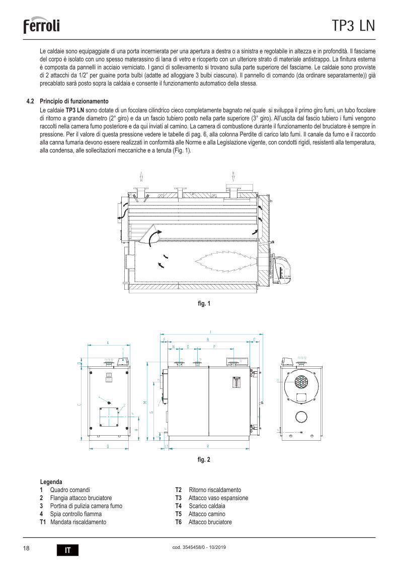
Le caldaie sono equipaggiate di una porta incernierata per una apertura a destra o a sinistra e regolabile in altezza e in profondità. Il fasciame del corpo è isolato con uno spesso materassino di lana di vetro e ricoperto con un ulteriore strato di materiale antistrappo. La finitura esterna è composta da pannelli in acciaio verniciato. I ganci di sollevamento si trovano sulla parte superiore del fasciame. Le caldaie sono provviste di 2 attacchi da 1/2” per guaine porta bulbi (adatte ad alloggiare 3 bulbi ciascuna). Il pannello di comando (da ordinare separatamente)) già precablato sarà posto sopra la caldaia e consente il funzionamento automatico della stessa.
4.2 Principio di funzionamentoLe caldaie TP3 LN sono dotate di un focolare cilindrico cieco completamente bagnato nel quale si sviluppa il primo giro fumi, un tubo focolare di ritorno a grande diametro (2° giro) e da un fascio tubiero posto nella parte superiore (3° giro). All’uscita dal fascio tubiero i fumi vengono raccolti nella camera fumo posteriore e da qui inviati al camino. La camera di combustione durante il funzionamento del bruciatore è sempre in pressione. Per il valore di questa pressione vedere le tabelle di pag. 6, alla colonna Perdite di carico lato fumi. Il canale da fumo e il raccordo alla canna fumaria devono essere realizzati in conformità alle Norme e alla Legislazione vigente, con condotti rigidi, resistenti alla temperatura, alla condensa, alle sollecitazioni meccaniche e a tenuta (Fig. 1).
Legenda1 Quadro comandi T2 Ritorno riscaldamento2 Flangia attacco bruciatore T3 Attacco vaso espansione3 Portina di pulizia camera fumo T4 Scarico caldaia4 Spia controllo fiamma T5 Attacco caminoT1 Mandata riscaldamento T6 Attacco bruciatore
3
T3T1T2
T4
T5
F B E
P
L1 R
I
T1-T3-T2
A
Q
CD
H
T6
1
T1-T3-T2
T4
T5
2
4
LG
M
0694
ModelloModel
230V - ~50 Hz
Elektrisk forsyning
Alimentazione elettricaElectrical InputAlimantation éléctriqueAlimentaciòn eléctrìca
ktrnhjgbnfybt
StromspannungStroomspanningAlimentacao elèctricaIngaende spanning
Potenza termica Nominale
l
cod. 313
50491
Nominal Power Output
Portata Termica NominaleNominal Power Input
kW
kW
Max Pressure Heatingbar
Max Temp. RiscaldamentoMax Temp Heating
°C
Max Press. Riscaldamento
No. MatricolaConstruction No.
Konstruktions-nr.Herstellnr.
NennwarmeleistungNominal warmtevermogen
NennheizwertNominaal verwarmingsvermogen
Max. WasserdruckMax. waterdruk
Max. KesseltemperaturMax. Ketelstemperatuur
Fabrikaatnr.No.de fabricationNo de construccaoValmistusnumeroPfdjlcrjq yjvthNo.de fabricacion
Dèbito tèrmico nominalDèbit thermique nominalNominell varmetillforselCaudal tèrmico nominal NtgkjghjbpdjlbntkmyjcnmNominel termisk forsyning
Puissance nominal Potencia NominalPotencia Nominal Nomineel effektNominel Kraft Gjktpyfz Ntgkjdfzvjoyjcnm
Pression maxi Chauffage Pressao màx. de caldeiraPresiòn màx. de Calefacciòn Max tryckVarmeanlaegets maks.-tryk Vfrc= hf,jxtt lfdktybt
Temperature maxi Chauffage Temperatura màx. de caldeiraTemper.màx.de Calefacciòn Max varmartemperaturVarmeanlaegets maks.-temperatur Vfrc= hf,jxfz ntvgthfnehf
H O
Codice PinCode
t.max safety 114°C
bar
Pressione prova idraul./DataHidraulic test pressure/DatePre ssi on d'é pre uve hy dra uli que /Da tePrueba presiòn hidràulica/FechaDruck wasserdruckprÜfung/Datum
Vandtrykprøve/DatoWaterdrukproef/DatumPressÃo do teste hidràulico/DataHydrauliskt testtryck/DatumJghtccjdjxyjt lfdkt ybt #Lfnf
VIA RI TON DA 78/ A - 37 047 SA N B ONI FACIO - V R - IT ALY
Vjltkm
Rjl
J,mtv rjnkjdjq djls
'
354
5051/1
MANDATADEPARTVORLAUFFLOWAANVOER
RITORNORETOURRUCKLAUFRETURN
3540
907/2
3540
908/2
ATTENZIONE35451110
ATTENTION
Prima di accendere il bruciatoreassicurarsi della tenuta del portelloneonde evitare di rovinare la guarnizione. Per la regolazione e l'apertura del portellone vedere libretto istruzioni.
Before firing the burner please check the gas-side tightness onto the ceramic fiber rope of the front door. For door hinges adjustment see instruction book.
ACHTUN G - Ei n mogl icher Splat zwisch en Bre nnerro hr und fe uerfes ter au skleidung is t mit kerami kfaser es Sei l ab zuschl iessen .
OPGELE T - De mogel ijke spleet tussen brand erpijp en br anderp laat m et hittebest endig koord afluit en.
ATTENT ION - L'inte rstice event uel en tre la tete du bru leur et le re veteme nt refactair e doit etre rempli par u n co rdon e n fibr e ceramique.
ATTENZ IONE - Chiud ere con un c ordone di fi bra ce ramica l' eventu ale fe ssura tra il canot to del bruci atore e il fo ro esi stente sulla porta .
CAUTIO N - Th e even tual gap bet ween b urner head a nd re fracto ry lin ing must be sealed by a cerami c fibe r ro pe.
cod.35450482
ON
fig. 2
fig. 1

19IT
TP3 LN
cod. 3545458/0 - 10/2019
4.3 Dati tecnici - Misure - Allacciamenti idraulici
TP3 LN 70 92 107 152 190 240 320 401 500
Potenzialità nominalemin. kW 46 60 70 100 137 160 196 260 341max. kW 70 92 107 152 190 240 320 401 500
Potenzialità focolaremin. kW 48 62,7 73,2 104,7 143,8 167,8 205,2 271,5 354,6max. kW 73,9 97,1 112,9 160,5 200,8 252,9 335,7 419,4 522,8
Perdite di carico lato acqua Dt 15ºC mbar 6 6 12 7 10 17 23 22 28Perdite di carico lato fumi mbar 0,54 0,89 1,2 1,65 1,8 2,4 3,3 4,4 5,43Perdite fumi* kg/h 119 156 182 258 321 405 539 670 838Pressione massima d’esercizio** bar 6 6 6 6 6 6 6 6 6Peso a secco standard 6 bar kg 236 236 332 332 460 524 833 833 1146
DIMENSIONI
A mm 670 670 670 670 760 760 820 820 855B mm 770 770 1190 1190 1190 1390 1590 1590 1990C mm 1116 1116 1116 1116 1271 1271 1456 1456 1546D mm 165 165 165 165 165 165 165 165 165E mm 146 146 146 146 165 165 184 184 184F mm 152 152 152 152 152 152 152 152 152G mm 880 880 880 880 985 985 1140 1140 1225H mm 390 390 390 390 420 420 460 460 480I mm 1130 1130 1555 1555 1570 1770 1990 1990 2390M mm 160 160 160 160 145 145 160 160 155
ATTACCHI
mandata T1 2” 1/2 2” 1/2 2” 1/2 2” 1/2 2” 1/2 2” 1/2 DN 80 DN 80 DN 100ritorno T1 2” 1/2 2” 1/2 2” 1/2 2” 1/2 2” 1/2 2” 1/2 DN 80 DN 80 DN 100sicurezze T3 1” 1/2 1” 1/2 1” 1/2 1” 1/2 1” 1/2 1” 1/2 DN 50 DN 50 DN 65scarico T4 3/4” 3/4” 3/4” 3/4” 3/4” 3/4” 3/4” 3/4” 3/4”uscita fumo T5 Ø mm 160 160 160 160 220 220 250 250 300attacco bruciatore T6 Ø mm 145 145 145 150 150 150 240 240 240lg. min/max boccaglio T6 250/320 250/320 250/320 250/320 250/320 250/320 250/320 290/360 290/360
TP3 LN 600 720 820 940 1060 1250 1480 1890 2360
Potenzialità nominalemin. kW 390 468 533 611 689 813 962 1229 1535max. kW 600 720 820 940 1060 1250 1480 1890 2360
Potenzialità focolaremin. kW 403,8 484,8 552,3 633,4 714,5 843,7 999,1 1278,1 1598,9max. kW 627,2 752,5 856,7 981,6 1106,3 1303,6 1542,0 1919,3 2449,8
Perdite di carico lato acqua Dt 15ºC mbar 18 25 25 33 40 55 45 70 65Perdite di carico lato fumi mbar 6,2 5,9 6,7 6,3 7,2 7 7,4 7,2 7,8Perdite fumi* kg/h 1005 1207 1376 1574 1774 2088 2474 3091 3947Pressione massima d’esercizio** bar 6 6 6 6 6 6 6 6 6Peso a secco standard 6 bar kg 1146 1557 1584 2329 2329 2601 2871 3552 4041
DIMENSIONI
A mm 855 990 990 1150 1150 1180 1180 1340 1340B mm 1990 1944 1944 2394 2394 2594 2894 2698 2998C mm 1546 1791 1791 2021 2021 2021 2021 2371 2371D mm 165 165 165 165 165 165 165 165 165E mm 184 184 184 206 206 206 206 206 206F mm 152 212 212 212 212 212 212 212 212G mm 1225 1395 1395 1625 1625 1605 1605 1920 1920H mm 480 530 530 600 600 575 575 670 670I mm 2390 2410 2410 2880 2880 3080 3380 3180 3480M mm 1615 1860 1860 2100 2100 2100 2100 2440 2440
ATTACCHI
mandata T1 DN 100 DN 125 DN 125 DN 150 DN 150 DN 150 DN 150 DN 200 DN 200ritorno T1 DN 100 DN 125 DN 125 DN 150 DN 150 DN 150 DN 150 DN 200 DN 200sicurezze T3 DN 65 DN 80 DN 80 DN 100 DN 100 DN 100 DN 100 DN 125 DN 125scarico T4 3/4” 3/4” 3/4” 1” 1/2 1” 1/2 1” 1/2 1” 1/2 1” 1/2 1” 1/2uscita fumo T5 Ø mm 300 350 350 400 400 450 450 500 500attacco bruciatore T6 Ø mm 210 210 270 270 270 270 350 350 350lg. min/max boccaglio T6 320/390 320/390 320/390 320/390 340/410 340/410 340/410 340/470 350/480
* Combustibile gasolio: CO2 = 13% - Combustibile gas: CO2 = 10%

20 IT
TP3 LN
cod. 3545458/0 - 10/2019
4.4 Identificazione La caldaia è identificabile attraverso:- Busta documenti (1) È attaccata sul portellone e contiene: MANUALE TECNICO CERTIFICATO DI GARANZIA ETICHETTE CON CODICE A BARRE TARGHETTA TECNICA CERTIFICATO DI COSTRUZIONE (attestante il buon esito della prova idraulica)
- Targhetta Tecnica (2) Riporta i dati tecnici e le prestazioni dell’apparecchio. È inserita nella busta documenti e DEVE ESSERE APPLICATA OBBLIGATORIAMENTE, dall’installatore dell’apparecchio, ad installazione ultimata, nella parte alta anteriore di uno dei pannelli laterali della mantellatura, in modo visibile. In caso di smarrimento richiederne un duplicato al Servizio Tecnico di Assistenza Ferroli.
La manomissione, l’asportazione, la mancanza della targhetta di identificazione o quant’altro non permetta la sicura identificazione del prodotto, rende difficoltosa qualsiasi operazione di installazione e manutenzione.
5. INSTALLAZIONE5.1 Imballo
Le caldaie TP3 LN vengono fornite complete di porta e camera fumo mon-tate e isolamento sul corpo, mentre la mantellatura è contenuta in imballo di cartone (Fig. 2). Il pannello strumenti (accessorio da ordinare separata-mente) viene fornito in una scatola di cartone e posizionato nella camera di combustione.
5.2 MovimentazioneLe caldaie TP3 LN sono dotate di golfare di sollevamento. Porre attenzione alla movimentazione e avvalersi di attrezzatura idonea ai loro pesi. Prima di posizionare la caldaia togliere il basamento in legno svitando le viti di fissaggio (Fig. 4).
fig. 3
1
2
0694
ModelloModel
230V - ~50 Hz
Elektrisk forsyning
Alimentazione elettricaElectrical InputAlimantation éléctriqueAlimentaciòn eléctrìca
StromspannungStroomspanningAlimentacao elèctricaIngaende spanning
Potenza termica Nominale
l
cod. 31350491
Nominal Power Output
Portata Termica NominaleNominal Power Input
kW
kW
Max Pressure Heatingbar
Max Temp. RiscaldamentoMax Temp Heating
°C
Max Press. Riscaldamento
No. MatricolaConstruction No.
Konstruktions-nr.Herstellnr.
NennwarmeleistungNominal warmtevermogen
NennheizwertNominaal verwarmingsvermogen
Max. WasserdruckMax. waterdruk
Max. KesseltemperaturMax. Ketelstemperatuur
Fabrikaatnr.No.de fabricationNo de construccaoValmistusnumero
No.de fabricacion
Dèbito tèrmico nominalDèbit thermique nominalNominell varmetillforselCaudal tèrmico nominal
Nominel termisk forsyning
Puissance nominal Potencia NominalPotencia Nominal Nomineel effektNominel Kraft
Pression maxi Chauffage Pressao màx. de caldeiraPresiòn màx. de Calefacciòn Max tryckVarmeanlaegets maks.-tryk
Temperature maxi Chauffage Temperatura màx. de caldeiraTemper.màx.de Calefacciòn Max varmartemperaturVarmeanlaegets maks.-temperatur
H O
Codice PinCode
t.max safety 114°C
bar
Pressione prova idraul./DataHidraulic test pressure/DatePression d'épreuve hydraulique/DatePrueba presiòn hidràulica/FechaDruck wasserdruckprÜfung/Datum
Vandtrykprøve/DatoWaterdrukproef/DatumPressÃo do teste hidràulico/DataHydrauliskt testtryck/Datum
VIA RITONDA 78/A - 37047 SAN BONIFACIO - VR - ITALY
Заводской номер
Теплопроизводительность
Полезная Тепловаямошность
Макс. рабочее давление
Макс. рабочее температура
Обьем котловой воды
Опрессовочное давление/Дата
Электропитание
Код
Модель
2
1
fig. 4

21IT
TP3 LN
cod. 3545458/0 - 10/2019
5.3 Locale di installazione (Fig. 5)Le caldaie TP3 LN vanno installate in locali ad uso esclusivo, rispondenti alle Norme Tecniche e alla Legislazione vigente e dotati di aperture di aerazione adeguatamente dimensionate. Le aperture di aerazione dovranno essere permanenti, comunicanti direttamente con l’esterno e posizionate a livello alto e basso in conformità con le normative vigenti. L’ubicazione delle aperture di aerazione, i circuiti di adduzione del combustibile, di distribuzione dell’energia elettrica e di illuminazione dovranno rispettare le disposizioni di legge vigenti in relazione al tipo di combustibile impiegato. Per agevolare la pulizia del circuito fumo, nella parte anteriore della caldaia, dovrà essere lasciato uno spazio libero non inferiore alla lunghezza del corpo caldaia e, in ogni caso, mai inferiore a 1300 mm e si dovrà verificare che con la porta aperta a 90° la distanza tra la porta e la parete adiacente (X), sia almeno pari alla lunghezza del bruciatore.Il piano d’appoggio della caldaia deve essere perfettamente orizzontale. È consigliabile prevedere uno zoccolo di cemento piano e in grado di sopportare il peso totale della caldaia più il contenuto d’acqua. Per le dimensioni dello zoccolo, vedere le quote R x Q (tabella dimensioni).Nel caso in cui il bruciatore sia alimentato con gas combustibile di peso specifico superiore a quello dell’aria, le parti elettriche dovranno essere poste ad una quota da terra superiore a 500 mm. L’apparecchio non può essere installato all’aperto perché non è progettato per funzionare all’esterno e non dispone di sistemi antigelo automatici.
COLLOCAZIONE IN IMPIANTI OBSOLETINel caso in cui la caldaia venga collocata in impianti obsoleti, verificare che:
- La canna fumaria sia adeguata alle temperature dei prodotti di combustione, che sia calcolata e costruita in conformità alla normativa vi-gente, che sia a tenuta stagna, isolata e che non vi siano ostruzioni o restringimenti.
- L’impianto elettrico sia stato realizzato in conformità alle norme vigenti e dal personale qualificato. - La linea di fornitura del combustibile e l’eventuale deposito siano stati realizzati in conformità alle norme vigenti. - Il/I vaso/i di espansione garantisca/garantiscano il totale assorbimento della dilatazione del fluido contenuto nell’impianto. - La portata, la pressione statica, la direzione del flusso delle pompe di circolazione siano adeguati. - L’impianto sia ripulito da fanghi e incrostazioni, che l’aria sia stata eliminata e che la tenuta stagna sia stata verificata. - Sia stato previsto un sistema di trattamento dell’acqua di alimentazione/rifornimento (v. valori di riferimento).
600
600
1000
X
1000
fig. 5

22 IT
TP3 LN
cod. 3545458/0 - 10/2019
5.4 Scarico dei prodotti di combustione (Fig. 6)Il canale da fumo e il raccordo alla canna fumaria devono essere realizzati in con-formità alle Norme e alla Legislazione vigente, con condotti rigidi, resistenti alla tem-peratura, alla condensa, alle sollecitazioni meccaniche e a tenuta. La canna fumaria deve assicurare la depressione minima prevista dalle Norme vigenti, considerando pressione “zero” al raccordo con canale da fumi. Canne fumarie e canali da fumo ina-deguati o mal dimensionati possono ampliare la rumorosità di combustione, generare problemi di condensazione e influire negativamente sui parametri di combustione. I condotti di scarico non coibentati sono fonte di potenziale pericolo. Le tenute delle giunzioni vanno realizzate con materiali resistenti a temperature di almeno 250°C. Nel tratto di collegamento tra caldaia e canna fumaria, si devono prevedere idonei punti di misura per la temperatura fumi e l’analisi dei prodotti della combustione. Per quanto riguarda la sezione e l’altezza del camino, è necessario fare riferimento alle regolamentazioni nazionali e locali in vigore.
ATTENZIONE: è possibile la formazione di condensa all’interno del camino, a causa della bassa temperatura dei fumi.
5.5 Collegamenti idraulici5.5.1 Acqua di alimentazione
Le caratteristiche chimiche dell’acqua dell’impianto e di reintegro, sono fondamen-tali per il buon funzionamento e la sicurezza della caldaia, vanno condizionate con opportuni sistemi di trattamento. Come valori di riferimento possono essere consi-derati quelli riportati nella tabella.
DUREZZA TOTALE ppm 10ALCALINITÀ mg/l CaCO3 750PH 8÷9SILICE ppm 100CLORURI ppm 3500
È assolutamente indispensabile il trattamento dell’acqua utilizzata per l’impianto di riscaldamento nei seguenti casi:- Impianti molto estesi.- Acqua con elevata durezza.- Frequenti immissioni di acqua di reintegro nell’impianto.
Nel caso si rendesse necessario lo svuotamento parziale o totale dell’impianto, si prescrive di effettuare il successivo riempimento con acqua trattata. Per il controllo dell’entità dei reintegri si consiglia di installare sulla tubazione un contatore. I fenomeni più comuni che si verificano negli impianti termici sono:
- Incrostazioni di calcare Il calcare si concentra nei punti dove maggiore è la temperatura di parete. Le incrostazioni calcaree a causa della loro bassa conduttività ter-
mica riducono lo scambio termico così che la presenza di pochi millimetri, contrastano lo scambio termico tra i fumi e l’acqua, comportando un aumento della temperatura delle parti esposte alla fiamma e quindi rotture (cricche) sulla piastra tubiera.
- Corrosione lato acqua La corrosione delle superfici metalliche della caldaia lato acqua è dovuta al passaggio in soluzione del ferro attraverso i suoi ioni. In questo
processo ha molta importanza la presenza dei gas disciolti e in particolare dell’ossigeno e dell’anidride carbonica. In presenza di acque addolcite e/o demineralizzate, si è al riparo da fenomeni di incrostazione, ma non altrettanto per quanto riguarda le corrosioni. È necessario quindi condizionare l’acqua con inibitori di processi corrosivi.
5.5.2 Tubazioni mandata/ritorno impiantoLe dimensioni delle tubazioni di mandata e ritorno sono indicate per ogni modello di caldaia nella tabella DIMENSIONI.Assicurarsi che sull’impianto ci sia un numero sufficiente di sfiati. Gli attacchi della caldaia non devono essere sollecitati dal peso delle tubazioni d’allacciamento all’impianto; installare pertanto appositi supporti.
5.5.3 Tubazioni riempimento/scarico impiantoPer il riempimento e lo scarico della caldaia un rubinetto può essere collegato all’attacco T4 che si trova nella parte posteriore (vedi disegno DIMENSIONI).
fig. 6
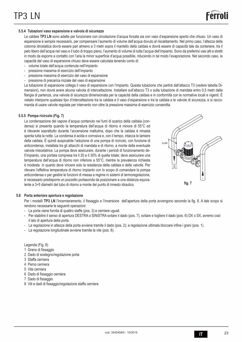
23IT
TP3 LN
cod. 3545458/0 - 10/2019
5.5.4 Tubazioni vaso espansione e valvola di sicurezzaLe caldaie TP3 LN sono adatte per funzionare con circolazione d’acqua forzata sia con vaso d’espansione aperto che chiuso. Un vaso di espansione è sempre necessario, per compensare l’aumento di volume dell’acqua dovuto al riscaldamento. Nel primo caso, l’altezza della colonna idrostatica dovrà essere pari almeno a 3 metri sopra il mantello della caldaia e dovrà essere di capacità tale da contenere, tra il pelo libero dell’acqua nel vaso e il tubo di troppo pieno, l’aumento di volume di tutta l’acqua dell’impianto. Sono da preferirsi vasi alti e stretti in modo da esporre a contatto con l’aria la minor superficie d’acqua possibile, riducendo in tal modo l’evaporazione. Nel secondo caso, la capacità del vaso di espansione chiuso deve essere calcolata tenendo conto di: - volume totale dell’acqua contenuta nell’impianto- pressione massima di esercizio dell’impianto- pressione massima di esercizio del vaso di espansione- pressione di precarica iniziale del vaso di espansioneLa tubazione di espansione collega il vaso di espansione con l’impianto. Questa tubazione che partirà dall’attacco T3 (vedere tabella Di-mensioni), non dovrà avere alcuna valvola di intercettazione. Installare sull’attacco T3 o sulla tubazione di mandata entro 0,5 metri dalla flangia di partenza, una valvola di sicurezza dimensionata per la capacità della caldaia e in conformità con le normative locali e vigenti. È vietato interporre qualsiasi tipo d’intercettazione tra la caldaia e il vaso d’espansione e tra la caldaia e le valvole di sicurezza, e si racco-manda di usare valvole regolate per intervento non oltre la pressione massima di esercizio consentita.
5.5.5 Pompa ricircolo (Fig. 7)La condensazione del vapore d’acqua contenuto nei fumi di scarico della caldaia (con-densa) si presenta quando la temperatura dell’acqua di ritorno è minore di 55°C ed è rilevante soprattutto durante l’accensione mattutina, dopo che la caldaia è rimasta spenta tutta la notte. La condensa è acida e corrosiva e, con il tempo, intacca le lamiere della caldaia. È quindi auspicabile l’adozione di una pompa di ricircolo, con funzione di anticondensa, installata tra gli attacchi di mandata e di ritorno, a monte della eventuale valvola miscelatrice. La pompa deve assicurare, durante i periodi di funzionamento de-ll’impianto, una portata compresa tra il 20 e il 30% di quella totale; deve assicurare una temperatura dell’acqua di ritorno non inferiore a 55°C, mentre la prevalenza richiesta è modesta in quanto deve vincere solo la resistenza della caldaia e delle valvole. Per rilevare l’effettiva temperatura di ritorno impianto con lo scopo di comandare la pompa anticondensa o per gestire le funzioni di messa a regime in sistemi di termoregolazione, è necessario predisporre un pozzetto portasonda da posizionare a una distanza equiva-lente a 3÷5 diametri del tubo di ritorno a monte del punto di innesto idraulico.
5.6 Porta anteriore apertura e regolazionePer i modelli TP3 LN l’incernieramento, il fissaggio e l’inversione dell’apertura della porta avvengono secondo la fig. 8. A tale scopo si rendono necessarie le seguenti operazioni:- La porta viene fornita di quattro staffe (pos. 3) e cerniere uguali.- Per stabilire il senso di apertura DESTRA o SINISTRA svitare il dado (pos. 7), svitare e togliere il dado (pos. 6) DX o SX, avremo così il lato di apertura della porta. - La regolazione in altezza della porta avviene tramite il dado (pos. 2); a regolazione ultimata bloccare infine i grani (pos. 1).- La regolazione longitudinale avviene tramite la vite (pos. 8).
Legenda (Fig. 8)1 Grano di fissaggio2 Dado di sostegno/regolazione porta3 Staffa cerniera4 Perno cerniera5 Vite cerniera6 Dado di fissaggio cerniera 7 Dado di fissaggio8 Viti e dadi di fissaggio/regolazione staffa cerniera
fig. 7

24 IT
TP3 LN
cod. 3545458/0 - 10/2019
5.7 Montaggio del bruciatore (Fig. 9)
Il montaggio del bruciatore alla porta della caldaia, deve garantire una perfetta tenuta ai prodotti della combustione. Installato il bruciatore sulla caldaia, lo spazio tra il boccaglio del bruciatore e il materiale refrattario del portellone deve essere riempito con il materassino ceramico (A) fornito a corredo. Questa operazione evita il surriscaldamento del portellone che altrimenti si deformerebbe in maniera irrimediabile.
Gli allacciamenti del combustibile al bruciatore dovranno essere posti in modo da consentire la completa apertura del portellone della caldaia con il bruciatore installato.
Modelli L min. (mm) L max. (mm) 70-152 230 300 190-240 250 320 320-401 290 360 500-600 320 390 720-820 320 390 940-1060 340 4101250-1480 340 4701890-2360 350 480
123
5
6
7
8
8
4
fig. 8
L
A
fig. 9
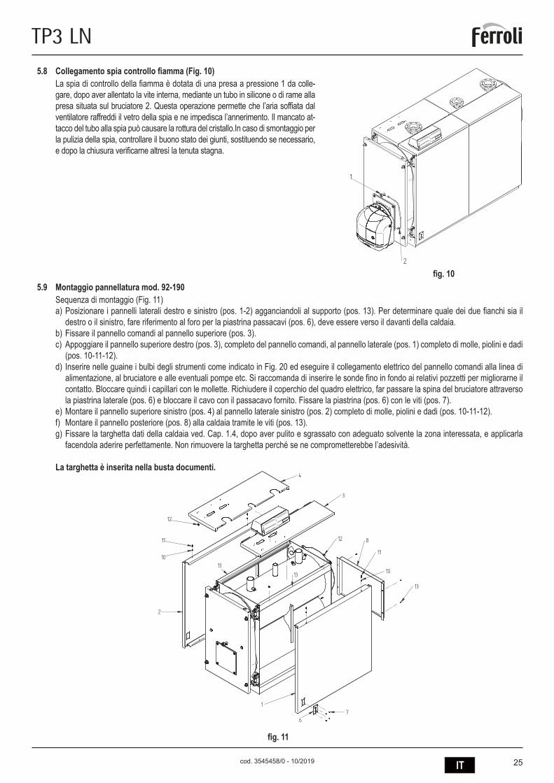
25IT
TP3 LN
cod. 3545458/0 - 10/2019
5.8 Collegamento spia controllo fiamma (Fig. 10)La spia di controllo della fiamma è dotata di una presa a pressione 1 da colle-gare, dopo aver allentato la vite interna, mediante un tubo in silicone o di rame alla presa situata sul bruciatore 2. Questa operazione permette che l’aria soffiata dal ventilatore raffreddi il vetro della spia e ne impedisca l’annerimento. Il mancato at-tacco del tubo alla spia può causare la rottura del cristallo.In caso di smontaggio per la pulizia della spia, controllare il buono stato dei giunti, sostituendo se necessario, e dopo la chiusura verificarne altresì la tenuta stagna.
5.9 Montaggio pannellatura mod. 92-190Sequenza di montaggio (Fig. 11)a) Posizionare i pannelli laterali destro e sinistro (pos. 1-2) agganciandoli al supporto (pos. 13). Per determinare quale dei due fianchi sia il
destro o il sinistro, fare riferimento al foro per la piastrina passacavi (pos. 6), deve essere verso il davanti della caldaia.b) Fissare il pannello comandi al pannello superiore (pos. 3).c) Appoggiare il pannello superiore destro (pos. 3), completo del pannello comandi, al pannello laterale (pos. 1) completo di molle, piolini e dadi
(pos. 10-11-12).d) Inserire nelle guaine i bulbi degli strumenti come indicato in Fig. 20 ed eseguire il collegamento elettrico del pannello comandi alla linea di
alimentazione, al bruciatore e alle eventuali pompe etc. Si raccomanda di inserire le sonde fino in fondo ai relativi pozzetti per migliorarne il contatto. Bloccare quindi i capillari con le mollette. Richiudere il coperchio del quadro elettrico, far passare la spina del bruciatore attraverso la piastrina laterale (pos. 6) e bloccare il cavo con il passacavo fornito. Fissare la piastrina (pos. 6) con le viti (pos. 7).
e) Montare il pannello superiore sinistro (pos. 4) al pannello laterale sinistro (pos. 2) completo di molle, piolini e dadi (pos. 10-11-12).f) Montare il pannello posteriore (pos. 8) alla caldaia tramite le viti (pos. 13). g) Fissare la targhetta dati della caldaia ved. Cap. 1.4, dopo aver pulito e sgrassato con adeguato solvente la zona interessata, e applicarla
facendola aderire perfettamente. Non rimuovere la targhetta perché se ne comprometterebbe l’adesività.
La targhetta è inserita nella busta documenti.
2
1
fig. 10
1
2
3
1310
67
10
11
13
12
4
11
12
8
13
fig. 11

26 IT
TP3 LN
cod. 3545458/0 - 10/2019
5.10 Montaggio pannellatura mod. 240-2360Sequenza di montaggio (Fig. 12)a) Posizionare i pannelli laterali (pos. 1-2 e 3-4) agganciandoli ai supporti (pos. 19).b) Posizionare i pannelli laterali superiori destri (pos. 5-6) e successivamente i sinistri (7-8) agganciandoli ai supporti della caldaia (pos. 19) e
al traverso (pos. 15).c) Fissare il pannello comandi al pannello superiore destro (pos. 5).d) Appoggiare il pannello superiore (pos. 5), completo del pannello comandi, al pannello laterale (pos. 1) completo di molle, piolini e dadi (pos.
12-13-14).e) Inserire nelle guaine i bulbi degli strumenti come indicato in Fig. 19 ed eseguire il collegamento elettrico del pannello comandi alla linea di
alimentazione, al bruciatore e alle eventuali pompe etc. Si raccomanda di inserire le sonde fino in fondo ai relativi pozzetti per migliorarne il contatto. Bloccare quindi i capillari con le mollette. Richiudere il coperchio del quadro elettrico, far passare la spina del bruciatore attraverso la piastrina laterale (pos. 10) e bloccare il cavo con il passacavo fornito. Fissare la piastrina (pos. 10) con le viti (pos. 11.
f) Montare il sostegno (pos. 15).g) Montare i pannelli superiori (pos. 5-6-7-8) agganciandoli ai pannelli laterali (pos. 1-2-3-4) completi di molle, piolini e dadi (12-13-14).h) Fissare la targhetta dati della caldaia ved. Cap. 1.4, dopo aver pulito e sgrassato con adeguato solvente la zona interessata, e applicarla
facendola aderire perfettamente. Non rimuovere la targhetta perché se ne comprometterebbe l’adesività.
La targhetta è inserita nella busta documenti.
1
2
3
4
5
6
7
8
10
11
12
13
14
15
9 1119
fig. 12

27IT
TP3 LN
cod. 3545458/0 - 10/2019
6. MESSA IN FUNZIONE6.1 Controlli preliminari
Realizzati gli allacciamenti idraulici, elettrici e del combustibile alla caldaia, prima della messa in funzione è necessario verificare che: - Il vaso di espansione e la valvola di sicurezza siano correttamente collegati e non siano in alcun modo intercettabili. - I bulbi dei termostati di regolazione, di sicurezza della temperatura minima e del termometro siano introdotti nelle rispettive guaine. - Le turboeliche siano situate in tutti i tubi dei fumi. - L’impianto sia pieno d’acqua e l’aria sia totalmente assente. - La pompa o le pompe funzionino correttamente. - Gli allacciamenti idraulici, elettrici e di sicurezza necessari e del combustibile siano stati realizzati in conformità alle disposizioni nazionali
e locali in vigore. - Il bruciatore sia stato montato in conformità alle istruzioni riportate nel manuale del fabbricante. - La tensione e la frequenza di rete siano compatibili con il bruciatore e il sistema elettrico della caldaia. - L’impianto sia in grado di assorbire la quantità di calore che verrà prodotta. - La pompa di ricircolo sia installata come descritto nel paragrafo 5.5.5.
6.2 Prima accensioneDopo gli esiti positivi dalle verifiche indicate nel paragrafo anteriore, si potrà procedere alla prima accensione del bruciatore, che dovrà essere effettuata da un tecnico in servizio e riconosciuto dall’azienda fabbricante del bruciatore. Il tecnico assumerà tutta la responsabilità relativa al campo di regolazione all’interno del campo di potenza dichiarato e omologato della caldaia. Dopo aver aperto i rubinetti di blocco del combus-tibile e controllato che non vi siano perdite nella rete di fornitura, impostare tutti gli interruttori in posizione ON (collegato). In questo modo, il bruciatore è pronto per la prima accensione e per la regolazione che compete unicamente al tecnico autorizzato.Durante la prima accensione, sarà necessario verificare che lo sportello, la flangia del bruciatore e i collegamenti con la canna fumaria siano a tenuta stagna e che la base della canna fumaria presenti una leggera pressione negativa. La portata del combustibile dovrà corrispondere ai dati della targhetta della caldaia e, in nessun caso, dovrà essere superiore al valore massimo della potenza nominale dichiarata. La temperatura dei fumi non dovrà mai essere inferire a 160°C.
6.3 Spegnimento della caldaia - Regolare il termostato d’esercizio al minimo. - Eliminare la tensione dal bruciatore e chiudere l’alimentazione del combustibile. - Lasciar funzionare le pompe fino a quando non vengono chiuse dal termostato di temperatura minima. - Eliminare la tensione dal quadro elettrico.
7. MANUTENZIONE7.1 Norme generali
La manutenzione periodica è essenziale per la sicurezza, il rendimento e la durata dell’apparecchio.Tutte le operazioni devono essere effettuate dal personale qualificato. Ogni operazione di pulizia e manutenzione dovrà essere preceduta dalla chiusura dell’alimentazione del combustibile, una volta rimossa la tensione elettrica.Per ottenere un buon funzionamento e il massimo rendimento della caldaia, è necessaria la pulizia regolare della camera di combustione, dei tubi dei fumi e della camera dei fumi.
7.2 Manutenzione ordinariaLa manutenzione deve essere stabilita in base al combustibile usato, al numero di accensioni, alle caratteristiche dell’impianto ecc.; di conse-guenza, non è possibile stabilire a priori un intervallo di tempo tra una manutenzione e la successiva.In linea di principio, si consigliano i seguenti intervalli di pulizia in base al combustibile:
- Caldaie a gas: una volta all’anno - Caldaie a gasolio: due volte all’anno
In tutti i casi, sarà necessario rispettare le eventuali norme locali riguardanti la manutenzione.Durante le operazioni di manutenzione ordinaria, dopo aver rimosso le turboeliche, sarà necessario pulire con uno scopettone il fascio tubiero e il focolare. Rimuovere i depositi accumulati nella camera dei fumi tramite l’apertura degli sportelli d’ispezione. In caso di azioni più energiche, rimuovere la camera dei fumi posteriori e, se deteriorata, sostituire la guarnizione di tenuta stagna dei fumi. Verificare che lo scarico dell’acqua di condensa non sia ostruito. Sarà necessario comprovare il buon funzionamento degli organi di controllo e di misurazione del generatore.In questa occasione, sarà necessario registrare la quantità di acqua di rifornimento utilizzata, dopo aver effettuato le opportune analisi sull’acqua; effettuare quindi una disincrostazione preventiva.I sali di calcio e di magnesio disciolti nell’acqua ordinaria, con ripetuti rabbocchi, danno origine a depositi nella caldaia e provocano il surris-caldamento delle lamiere, con la possibilità che si producano danni non attribuibili né ai materiali né alla tecnica di fabbricazione e, pertanto, non coperti dalla garanzia. Dopo aver effettuato le operazioni di manutenzione e pulizia e la successiva accensione, verificare la tenuta stagna dello sportello e della camera dei fumi; in caso di perdite del prodotti di combustione, sostituire la guarnizione di tenuta stagna corrispondente.Le operazioni realizzate verranno annotate nel registro generale.
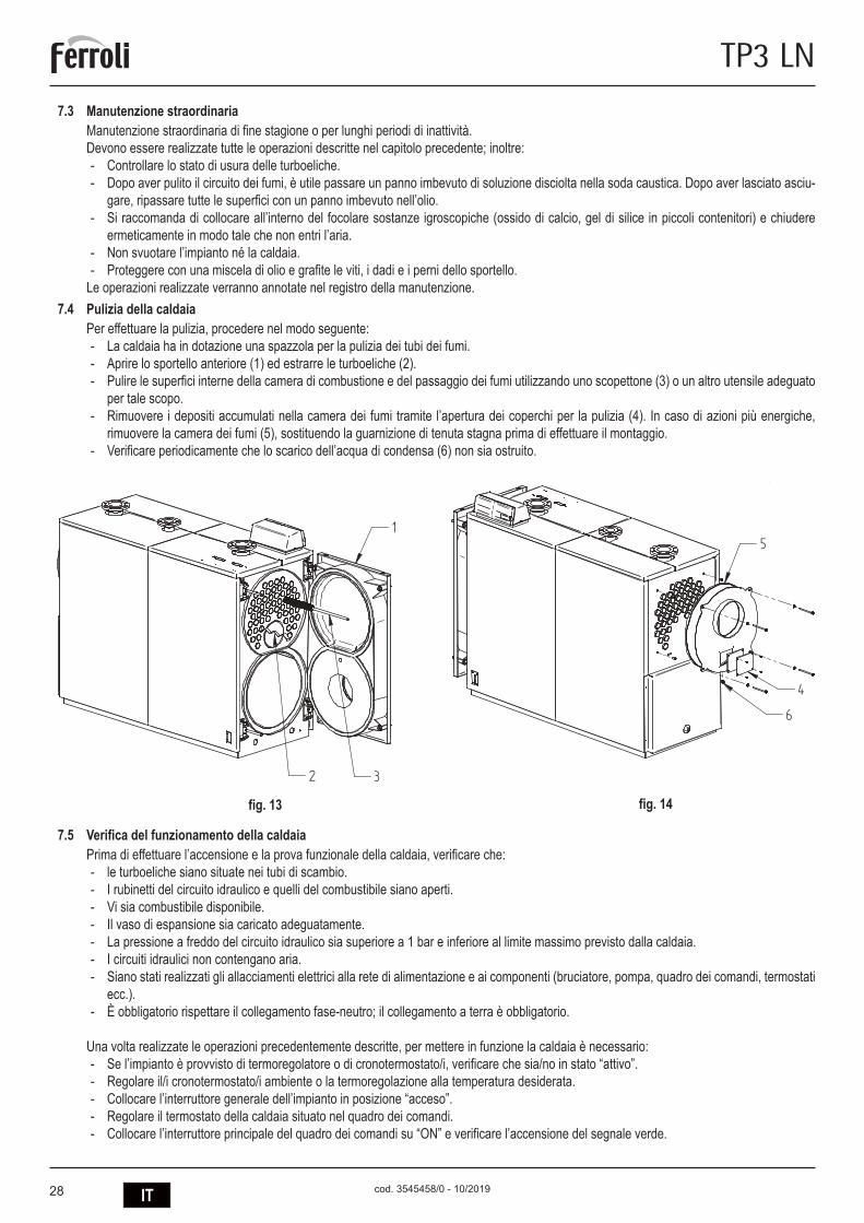
28 IT
TP3 LN
cod. 3545458/0 - 10/2019
7.3 Manutenzione straordinariaManutenzione straordinaria di fine stagione o per lunghi periodi di inattività.Devono essere realizzate tutte le operazioni descritte nel capitolo precedente; inoltre:
- Controllare lo stato di usura delle turboeliche. - Dopo aver pulito il circuito dei fumi, è utile passare un panno imbevuto di soluzione disciolta nella soda caustica. Dopo aver lasciato asciu-
gare, ripassare tutte le superfici con un panno imbevuto nell’olio. - Si raccomanda di collocare all’interno del focolare sostanze igroscopiche (ossido di calcio, gel di silice in piccoli contenitori) e chiudere
ermeticamente in modo tale che non entri l’aria. - Non svuotare l’impianto né la caldaia. - Proteggere con una miscela di olio e grafite le viti, i dadi e i perni dello sportello.
Le operazioni realizzate verranno annotate nel registro della manutenzione.7.4 Pulizia della caldaia
Per effettuare la pulizia, procedere nel modo seguente: - La caldaia ha in dotazione una spazzola per la pulizia dei tubi dei fumi. - Aprire lo sportello anteriore (1) ed estrarre le turboeliche (2). - Pulire le superfici interne della camera di combustione e del passaggio dei fumi utilizzando uno scopettone (3) o un altro utensile adeguato
per tale scopo. - Rimuovere i depositi accumulati nella camera dei fumi tramite l’apertura dei coperchi per la pulizia (4). In caso di azioni più energiche,
rimuovere la camera dei fumi (5), sostituendo la guarnizione di tenuta stagna prima di effettuare il montaggio. - Verificare periodicamente che lo scarico dell’acqua di condensa (6) non sia ostruito.
7.5 Verifica del funzionamento della caldaiaPrima di effettuare l’accensione e la prova funzionale della caldaia, verificare che:
- le turboeliche siano situate nei tubi di scambio. - I rubinetti del circuito idraulico e quelli del combustibile siano aperti. - Vi sia combustibile disponibile. - Il vaso di espansione sia caricato adeguatamente. - La pressione a freddo del circuito idraulico sia superiore a 1 bar e inferiore al limite massimo previsto dalla caldaia. - I circuiti idraulici non contengano aria. - Siano stati realizzati gli allacciamenti elettrici alla rete di alimentazione e ai componenti (bruciatore, pompa, quadro dei comandi, termostati
ecc.). - È obbligatorio rispettare il collegamento fase-neutro; il collegamento a terra è obbligatorio.
Una volta realizzate le operazioni precedentemente descritte, per mettere in funzione la caldaia è necessario: - Se l’impianto è provvisto di termoregolatore o di cronotermostato/i, verificare che sia/no in stato “attivo”. - Regolare il/i cronotermostato/i ambiente o la termoregolazione alla temperatura desiderata. - Collocare l’interruttore generale dell’impianto in posizione “acceso”. - Regolare il termostato della caldaia situato nel quadro dei comandi. - Collocare l’interruttore principale del quadro dei comandi su “ON” e verificare l’accensione del segnale verde.
fig. 13 fig. 14
5
4
6
1
32
5
4
6
1
32

29IT
TP3 LN
cod. 3545458/0 - 10/2019
La caldaia realizzerà la fase di accensione e rimarrà in funzionamento fino a quando non vengano raggiunte le temperature regolate. In caso di anomalie di accensione o di funzionamento, la caldaia andrà in “BLOCCO”, segnalato dal pilota rosso situato sul bruciatore e dal segnale rosso sul quadro dei comandi. Dopo un “BLOCCO”, attendere circa 30 secondi prima di ripristinare le condizioni di messa in funzione; per ripris-tinare le condizioni di messa in funzione, premere il “pulsante/pilota” del bruciatore e attendere che si accenda la fiamma. In caso di mancato funzionamento, è possibile ripetere questa operazione 2 o 3 volte al massimo; in seguito, verificare:El manual de instrucciones del quemador.
- Il capitolo “VERIFICA DEL FUNZIONAMENTO DELLA CALDAIA”. - Gli allacciamenti elettrici previsti nello schema che si trova accanto al quadro dei comandi.
Dopo aver effettuato la messa in funzione, è necessario verificare che l’apparecchio si arresta e che successivamente venga nuovamente messo in funzione:
- Modificando la regolazione del termostato della caldaia. - Intervenendo sull’interruttore principale del quadro dei comandi. - Intervenendo sul termostato ambiente o sul programmatore orario o sulla termoregolazione. - Verificando la libera e corretta rotazione delle pompe. - Verificando l’arresto totale della caldaia, agendo sull’interruttore generale dell’impianto.
Se sono state rispettate tutte le condizioni, rimettere in funzione l’apparecchio, effettuare il controllo della combustione (analisi dei fumi), della portata del combustibile e della tenuta stagna della guarnizione dello sportello e della camera dei fumi.
7.6 Verifica del funzionamento del bruciatore - Consultare il manuale d’istruzioni del bruciatore. - Attenersi a tutte le norme locali in materia di manutenzione del bruciatore.
7.7 Possibili anomalie e soluzioniDi seguito, viene riportato un elenco con le indicazioni delle principali anomalie e avarie che possono verificarsi nella gestione della caldaia, specificandone le possibili cause e soluzioni
ANOMALIEIL GENERATORE SI SPORCA FACILMENTECAUSA: Bruciatore regolato in modo non corretto SOLUZIONE: Controllare la regolazione del bruciatore (analisi dei fumi)
Canna fumaria ostruita Pulire il percorso dei fumi e la canna fumariaPercorso dell’aria del bruciatore sporco Pulire il percorso dell’aria del bruciatore
IL GENERATORE NON RIESCE AD AUMENTARE LA TEMPERATURACAUSA: Corpo del generatore sporco SOLUZIONE: Pulire il percorso dei fumi
Unione generatore/bruciatore Controllare i dati e le regolazioniPortata bruciatore insufficiente Controllare la regolazione del bruciatoreTermostato di regolazione Verificare il corretto funzionamento
Verificare la temperatura programmataIL GENERATORE ENTRA IN BLOCCO DI SICUREZZA TERMICA CON SEGNALE LUMINOSO NEL QUADRO DEI COMANDICAUSA: Termostato di regolazione SOLUZIONE: Verificare il corretto funzionamento
Verificare la temperatura programmataVerificare il cablaggio elettricoVerificare i bulbi delle sonde
Mancanza di acqua Verificare la pressione del circuitoPresenza dell’aria Verificare la valvola di spurgo
IL GENERATORE ACQUISISCE LA TEMPERATURA MA L’IMPIANTO DI RISCALDAMENTO È FREDDO CAUSA: Presenza dell’aria nell’impianto SOLUZIONE: Spurgare l’impianto
Pompa in avaria Sbloccare la pompaTermostato di temp. minima (se presente) Verificare la temperatura programmata
ODORI DI PRODOTTI NON BRUCIATICAUSA: Dispersione dei fumi in ambiente SOLUZIONE: Verificare la pulizia del corpo del generatore
Verificare la pulizia del condotto dei fumiVerificare l’ermeticità del generatore, dei condotti dei fumi e della canna fumaria
INTERVENTI FREQUENTI DELLA VALVOLA DI SICUREZZACAUSA: Pressione del circuito dell’impianto SOLUZIONE: Verificare la pressione di carico
Verificare il circuito dell’impiantoVerificare la regolazioneVerificare la temperatura programmata
Vaso di espansione dell’impianto Verificare
30 EN
TP3 LN
cod. 3545458/0 - 10/2019
1. INTRODUCTION ......................................................................................................................................................................... 312. GENERAL WARNINGS .............................................................................................................................................................. 313. CERTIFICATION ......................................................................................................................................................................... 314. TECHNICAL AND CONSTRUCTIONAL CHARACTERISTICS, DIMENSIONS ........................................................................ 314.1 Description of the appliance ........................................................................................................................................................................ 31
4.2 Operating principle ....................................................................................................................................................................................... 32
4.3 Technical data - Dimensions - Hydraulic connections ................................................................................................................................. 33
4.4 Identification ................................................................................................................................................................................................. 34
5. INSTALLATION .......................................................................................................................................................................... 345.1 Packaging .................................................................................................................................................................................................... 34
5.2 Handling ....................................................................................................................................................................................................... 34
5.3 Boiler room (Fig. 5) ...................................................................................................................................................................................... 35
5.4 Discharge of combustion products (Fig. 6) .................................................................................................................................................. 36
5.5 Hydraulic connections .................................................................................................................................................................................. 36
5.5.1 Supply water .......................................................................................................................................................................................... 36
5.5.2 Central heating outlet/return pipes ......................................................................................................................................................... 36
5.5.3 System fill/drain pipe .............................................................................................................................................................................. 36
5.5.4 Pipes, expansion vessel and safety valves ............................................................................................................................................ 37
5.5.5 Recirculation pump (Fig. 7) .................................................................................................................................................................... 37
5.6 Opening and adjusting the front door .......................................................................................................................................................... 37
5.7 Assembling the burner (Fig. 9) .................................................................................................................................................................... 38
5.8 Connecting the flame inspection window (Fig. 10) ...................................................................................................................................... 39
5.9 Assembling the panels, models 92÷190 ...................................................................................................................................................... 39
5.10 Assembling the panels, models 240÷2360 .................................................................................................................................................. 40
6. COMMISSIONING ...................................................................................................................................................................... 416.1 Preliminary checks ....................................................................................................................................................................................... 41
6.2 First ignition ................................................................................................................................................................................................. 41
6.3 Shutting down the boiler .............................................................................................................................................................................. 41
7. MAINTENANCE .......................................................................................................................................................................... 417.1 General instructions ..................................................................................................................................................................................... 41
7.2 Routine maintenance ................................................................................................................................................................................... 41
7.3 Special maintenance ................................................................................................................................................................................... 42
7.4 Cleaning the boiler ...................................................................................................................................................................................... 42
7.5 Checking boiler operation ............................................................................................................................................................................ 42
7.6 Checking burner operation .......................................................................................................................................................................... 43
7.7 Troubleshooting ........................................................................................................................................................................................... 43

31EN
TP3 LN
cod. 3545458/0 - 10/2019
1. INTRODUCTIONDear customer:Thank you for choosing a TP3 LN boiler. This manual was written to provide information, warnings and advice on the proper installation, use and maintenance of the boiler.Please read it carefully and save it for future reference. It is in your own interest to carefully follow and observe the instructions given in this manual, in order to fully enjoy this high-quality product.Failure to comply with and observe the instructions contained in this manual exonerates the manufacturer from all liability, and invalidates the warranty.
2. GENERAL WARNINGS - The instructions manual is an integral part of the product, and provides a description of all instructions that must be observed during the
installation, use and maintenance phase. - This appliance must only be used for the purpose for which it was expressly intended. - This appliance is intended to heat water to below-boiling temperatures at atmospheric pressure, and must be connected to a cen-
tral heating and/or domestic hot water distribution system, in accordance with its characteristics, performance, and heat output. - Before installation, check that the boiler has not been damaged during handling and transport. - The boiler is to be installed on a non-combustible base. - The boiler is to be installed with a distance of at least 100 mm to any combustible material or component. - The installation must be performed by duly qualified personnel, in accordance with current standards. - Before performing any cleaning or maintenance operations, unplug the appliance from the mains power supply. - THE MANUFACTURER is not liable for any damage to people or things due to errors in installation, adjustment, maintenance, or improper use. - The boiler and corresponding system must be commissioned by authorized personnel. - Commissioning is performed in order to verify proper operation of all adjustment and control devices. - Qualified personnel must be contacted if the appliance is not used for an extended period.
StandardsThe installer must observe current local regulations with regard to: the site chosen for the installation of the boiler, compliance with required ventila-tion conditions, the tightness of the connection to the chimney, connections to fuel lines, electrical systems, and any other relevant safety standards.Warranty conditions
The warranty is only valid if the standards and recommendations for use contained in this manual are observed. Any non-compliance or modifi-cation will void the warranty. The warranty does not cover damage caused by acidic condensate corrosion from the products of combustion, or the formation of deposits caused by the use of hard or aggressive water, as these are caused solely by system operation.
3. CERTIFICATION
The CE marking certifies that the products meet the essential requirements of the GAR regulation and other applicable directives.The declaration of conformity may be requested from the manufacturer.
PRODUCT IDENTIFICATION CODESTP3 LN 70 ORD099XA TP3 LN 320 ORD600XA TP3 LN 940 ORDG00XATP3 LN 92 ORD000XA TP3 LN 401 ORD800XA TP3 LN 1060 ORDH00XATP3 LN 107 ORD100XA TP3 LN 500 ORDB00XA TP3 LN 1250 ORDJ00XATP3 LN 152 ORD200XA TP3 LN 600 ORDD00XA TP3 LN 1480 ORDL00XATP3 LN 190 ORD300XA TP3 LN 720 ORDE00XA TP3 LN 1890 ORDP00XATP3 LN 240 ORD400XA TP3 LN 820 ORDF00XA TP3 LN 2360 ORDS00XA
PAESE DI DESTINAZIONE: ES - IT - FR - RU
4. TECHNICAL AND CONSTRUCTIONAL SPECIFICATIONS, DIMENSIONS4.1 Description of the appliance
The construction of the TP3 LN series boilers guarantees high output and efficiency at low flue gas temperatures, thus ensuring reduced pollu-ting emissions. The appliances are made according to the EN 303 standard, part 1.The main technical elements of the design are:- the careful design of the shapes, to ensure an optimum ratio between the combustion volumes and the heat exchange surfaces- the choice of materials used, for the long life of the boiler.The boilers use pressurised combustion, with three flue passes, overlapping double plating with completely cooled furnace on the bottom part and the tube bundle on the top part, and featuring turbulators to create a swirling path that increases the heat exchange by convection. On leaving the tube bundle, the flue gas enters the rear chamber and is transferred to the chimney.

32 EN
TP3 LN
cod. 3545458/0 - 10/2019
The boilers are fitted with a door featuring hinges that can be reversed for opening to the right or the left, and is adjustable in both height and depth. The body plating is insulated with a thick layer of glass wool, and covered with a further layer of tearproof material. The external finish consists of painted steel panels. The hoisting hooks are fitted on the top of the plating. The boilers feature two 1/2” fittings for bulb sheaths (able to house three bulbs each). The pre-wired control panel (to be ordered separately) is located above the boiler, and ensure automatic operation.
4.2 Operating principleThe TP3 LN boilers are fitted with a closed cylindrical furnace, in which the flame produced by the burner is reversed peripherally towards the front, from where the burned gas enters the fire tubes. At the outlet, the gas is collected in the smokebox and is then sent to the chimney. The combustion chamber is always pressurised during the operation of the burner. For the pressure values, see the tables on page 16, under the column Flue gas side pressure drop. The flue and the flue stack fitting must be made in compliance with the standards and the legislation in force, using rigid pipes that are resistant to high temperatures, condensate and mechanical stress, and are airtight (Fig. 1).
Key1 Control panel T2 Water return2 Burner mounting flange T3 Expansion vessel connection3 Smoke box cleaning door T4 Discharge/exhaust boiler4 Flame inspection window T5 Chimney connectionT1 Water delivery T6 Burner connection
3
T3T1T2
T4
T5
F B E
P
L1 R
I
T1-T3-T2
A
Q
CD
H
T6
1
T1-T3-T2
T4
T5
2
4
LG
M
0694
ModelloModel
230V - ~50 Hz
Elektrisk forsyning
Alimentazione elettricaElectrical InputAlimantation éléctriqueAlimentaciòn eléctrìca
ktrnhjgbnfybt
StromspannungStroomspanningAlimentacao elèctricaIngaende spanning
Potenza termica Nominale
l
cod. 313
50491
Nominal Power Output
Portata Termica NominaleNominal Power Input
kW
kW
Max Pressure Heatingbar
Max Temp. RiscaldamentoMax Temp Heating
°C
Max Press. Riscaldamento
No. MatricolaConstruction No.
Konstruktions-nr.Herstellnr.
NennwarmeleistungNominal warmtevermogen
NennheizwertNominaal verwarmingsvermogen
Max. WasserdruckMax. waterdruk
Max. KesseltemperaturMax. Ketelstemperatuur
Fabrikaatnr.No.de fabricationNo de construccaoValmistusnumeroPfdjlcrjq yjvthNo.de fabricacion
Dèbito tèrmico nominalDèbit thermique nominalNominell varmetillforselCaudal tèrmico nominal NtgkjghjbpdjlbntkmyjcnmNominel termisk forsyning
Puissance nominal Potencia NominalPotencia Nominal Nomineel effektNominel Kraft Gjktpyfz Ntgkjdfzvjoyjcnm
Pression maxi Chauffage Pressao màx. de caldeiraPresiòn màx. de Calefacciòn Max tryckVarmeanlaegets maks.-tryk Vfrc= hf,jxtt lfdktybt
Temperature maxi Chauffage Temperatura màx. de caldeiraTemper.màx.de Calefacciòn Max varmartemperaturVarmeanlaegets maks.-temperatur Vfrc= hf,jxfz ntvgthfnehf
H O
Codice PinCode
t.max safety 114°C
bar
Pressione prova idraul./DataHidraulic test pressure/DatePre ssi on d'é pre uve hy dra uli que /Da tePrueba presiòn hidràulica/FechaDruck wasserdruckprÜfung/Datum
Vandtrykprøve/DatoWaterdrukproef/DatumPressÃo do teste hidràulico/DataHydrauliskt testtryck/DatumJghtccjdjxyjt lfdkt ybt #Lfnf
VIA RI TON DA 78/ A - 37 047 SA N B ONI FACIO - V R - IT ALY
Vjltkm
Rjl
J,mtv rjnkjdjq djls
'
354
5051/1
MANDATADEPARTVORLAUFFLOWAANVOER
RITORNORETOURRUCKLAUFRETURN
3540
907/2
3540
908/2
ATTENZIONE35451110
ATTENTION
Prima di accendere il bruciatoreassicurarsi della tenuta del portelloneonde evitare di rovinare la guarnizione. Per la regolazione e l'apertura del portellone vedere libretto istruzioni.
Before firing the burner please check the gas-side tightness onto the ceramic fiber rope of the front door. For door hinges adjustment see instruction book.
ACHTUN G - Ei n mogl icher Splat zwisch en Bre nnerro hr und fe uerfes ter au skleidung is t mit kerami kfaser es Sei l ab zuschl iessen .
OPGELE T - De mogel ijke spleet tussen brand erpijp en br anderp laat m et hittebest endig koord afluit en.
ATTENT ION - L'inte rstice event uel en tre la tete du bru leur et le re veteme nt refactair e doit etre rempli par u n co rdon e n fibr e ceramique.
ATTENZ IONE - Chiud ere con un c ordone di fi bra ce ramica l' eventu ale fe ssura tra il canot to del bruci atore e il fo ro esi stente sulla porta .
CAUTIO N - Th e even tual gap bet ween b urner head a nd re fracto ry lin ing must be sealed by a cerami c fibe r ro pe.
cod.35450482
ON
fig. 2
fig. 1

33EN
TP3 LN
cod. 3545458/0 - 10/2019
4.3 Technical data - Dimensions - Hydraulic connections
TP3 LN 70 92 107 152 190 240 320 401 500
Heat outputmin. kW 46 60 70 100 137 160 196 260 341max. kW 70 92 107 152 190 240 320 401 500
Heat inputmin. kW 48 62,7 73,2 104,7 143,8 167,8 205,2 271,5 354,6max. kW 73,9 97,1 112,9 160,5 200,8 252,9 335,7 419,4 522,8
Water side load. loss Dt 15ºC mbar 6 6 12 7 10 17 23 22 28Flues side load. loss mbar 0,54 0,89 1,2 1,65 1,8 2,4 3,3 4,4 5,43Flue gas flow-rate* kg/h 119 156 182 258 321 405 539 670 838Max operating pressure** bar 6 6 6 6 6 6 6 6 6Weight 6 bars standard kg 236 236 332 332 460 524 833 833 1146
DIMENSIONS
A mm 670 670 670 670 760 760 820 820 855B mm 770 770 1190 1190 1190 1390 1590 1590 1990C mm 1116 1116 1116 1116 1271 1271 1456 1456 1546D mm 165 165 165 165 165 165 165 165 165E mm 146 146 146 146 165 165 184 184 184F mm 152 152 152 152 152 152 152 152 152G mm 880 880 880 880 985 985 1140 1140 1225H mm 390 390 390 390 420 420 460 460 480I mm 1130 1130 1555 1555 1570 1770 1990 1990 2390M mm 160 160 160 160 145 145 160 160 155
ATTACHMENTS
outlet T1 2” 1/2 2” 1/2 2” 1/2 2” 1/2 2” 1/2 2” 1/2 DN 80 DN 80 DN 100return T1 2” 1/2 2” 1/2 2” 1/2 2” 1/2 2” 1/2 2” 1/2 DN 80 DN 80 DN 100safety devices T3 1” 1/2 1” 1/2 1” 1/2 1” 1/2 1” 1/2 1” 1/2 DN 50 DN 50 DN 65discharge T4 3/4” 3/4” 3/4” 3/4” 3/4” 3/4” 3/4” 3/4” 3/4”flue gas outlet T5 Ø mm 160 160 160 160 220 220 250 250 300burner connection T6 Ø mm 145 145 145 150 150 150 240 240 240min/max draught tube length T6 250/320 250/320 250/320 250/320 250/320 250/320 250/320 290/360 290/360
TP3 LN 600 720 820 940 1060 1250 1480 1890 2360
Heat outputmin. kW 390 468 533 611 689 813 962 1229 1535max. kW 600 720 820 940 1060 1250 1480 1890 2360
Heat inputmin. kW 403,8 484,8 552,3 633,4 714,5 843,7 999,1 1278,1 1598,9max. kW 627,2 752,5 856,7 981,6 1106,3 1303,6 1542,0 1919,3 2449,8
Water side load. loss Dt 15ºC mbar 18 25 25 33 40 55 45 70 65Flues side load. loss mbar 6,2 5,9 6,7 6,3 7,2 7 7,4 7,2 7,8Flue gas flow-rate* kg/h 1005 1207 1376 1574 1774 2088 2474 3091 3947Max operating pressure** bar 6 6 6 6 6 6 6 6 6Weight 6 bars standard kg 1146 1557 1584 2329 2329 2601 2871 3552 4041
DIMENSIONS
A mm 855 990 990 1150 1150 1180 1180 1340 1340B mm 1990 1944 1944 2394 2394 2594 2894 2698 2998C mm 1546 1791 1791 2021 2021 2021 2021 2371 2371D mm 165 165 165 165 165 165 165 165 165E mm 184 184 184 206 206 206 206 206 206F mm 152 212 212 212 212 212 212 212 212G mm 1225 1395 1395 1625 1625 1605 1605 1920 1920H mm 480 530 530 600 600 575 575 670 670I mm 2390 2410 2410 2880 2880 3080 3380 3180 3480M mm 1615 1860 1860 2100 2100 2100 2100 2440 2440
ATTACHMENTS
outlet T1 DN 100 DN 125 DN 125 DN 150 DN 150 DN 150 DN 150 DN 200 DN 200return T1 DN 100 DN 125 DN 125 DN 150 DN 150 DN 150 DN 150 DN 200 DN 200safety devices T3 DN 65 DN 80 DN 80 DN 100 DN 100 DN 100 DN 100 DN 125 DN 125discharge T4 3/4” 3/4” 3/4” 1” 1/2 1” 1/2 1” 1/2 1” 1/2 1” 1/2 1” 1/2flue gas outlet T5 Ø mm 300 350 350 400 400 450 450 500 500burner connection T6 Ø mm 210 210 270 270 270 270 350 350 350min/max draught tube length T6 320/390 320/390 320/390 320/390 340/410 340/410 340/410 340/470 350/480
* Oil fuel: CO2 = 13% - Gas fuel: CO2 = 10%
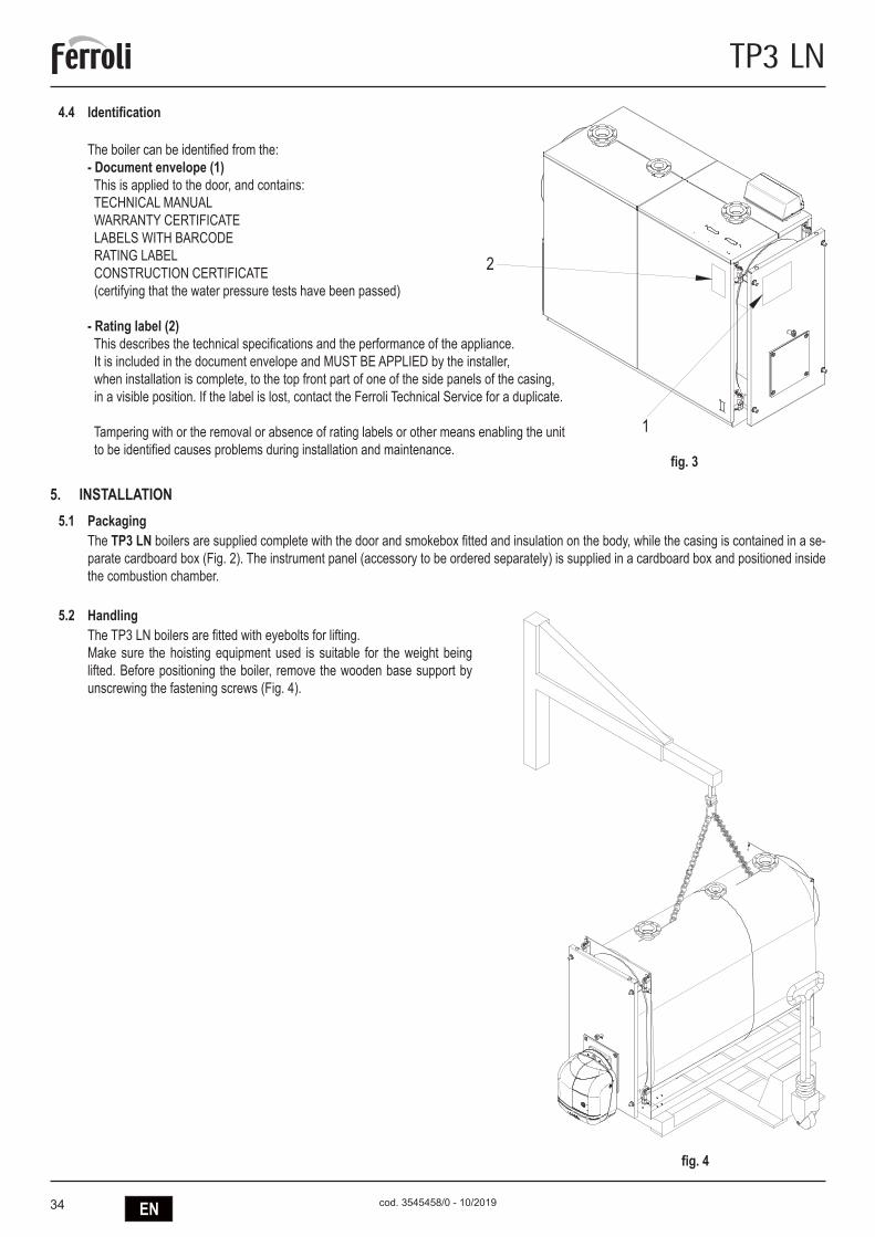
34 EN
TP3 LN
cod. 3545458/0 - 10/2019
4.4 Identification The boiler can be identified from the:- Document envelope (1) This is applied to the door, and contains: TECHNICAL MANUAL WARRANTY CERTIFICATE LABELS WITH BARCODE RATING LABEL CONSTRUCTION CERTIFICATE (certifying that the water pressure tests have been passed)
- Rating label (2) This describes the technical specifications and the performance of the appliance. It is included in the document envelope and MUST BE APPLIED by the installer, when installation is complete, to the top front part of one of the side panels of the casing, in a visible position. If the label is lost, contact the Ferroli Technical Service for a duplicate.
Tampering with or the removal or absence of rating labels or other means enabling the unit to be identified causes problems during installation and maintenance.
5. INSTALLATION5.1 Packaging
The TP3 LN boilers are supplied complete with the door and smokebox fitted and insulation on the body, while the casing is contained in a se-parate cardboard box (Fig. 2). The instrument panel (accessory to be ordered separately) is supplied in a cardboard box and positioned inside the combustion chamber.
5.2 HandlingThe TP3 LN boilers are fitted with eyebolts for lifting. Make sure the hoisting equipment used is suitable for the weight being lifted. Before positioning the boiler, remove the wooden base support by unscrewing the fastening screws (Fig. 4).
fig. 3
1
2
0694
ModelloModel
230V - ~50 Hz
Elektrisk forsyning
Alimentazione elettricaElectrical InputAlimantation éléctriqueAlimentaciòn eléctrìca
StromspannungStroomspanningAlimentacao elèctricaIngaende spanning
Potenza termica Nominale
l
cod. 31350491
Nominal Power Output
Portata Termica NominaleNominal Power Input
kW
kW
Max Pressure Heatingbar
Max Temp. RiscaldamentoMax Temp Heating
°C
Max Press. Riscaldamento
No. MatricolaConstruction No.
Konstruktions-nr.Herstellnr.
NennwarmeleistungNominal warmtevermogen
NennheizwertNominaal verwarmingsvermogen
Max. WasserdruckMax. waterdruk
Max. KesseltemperaturMax. Ketelstemperatuur
Fabrikaatnr.No.de fabricationNo de construccaoValmistusnumero
No.de fabricacion
Dèbito tèrmico nominalDèbit thermique nominalNominell varmetillforselCaudal tèrmico nominal
Nominel termisk forsyning
Puissance nominal Potencia NominalPotencia Nominal Nomineel effektNominel Kraft
Pression maxi Chauffage Pressao màx. de caldeiraPresiòn màx. de Calefacciòn Max tryckVarmeanlaegets maks.-tryk
Temperature maxi Chauffage Temperatura màx. de caldeiraTemper.màx.de Calefacciòn Max varmartemperaturVarmeanlaegets maks.-temperatur
H O
Codice PinCode
t.max safety 114°C
bar
Pressione prova idraul./DataHidraulic test pressure/DatePression d'épreuve hydraulique/DatePrueba presiòn hidràulica/FechaDruck wasserdruckprÜfung/Datum
Vandtrykprøve/DatoWaterdrukproef/DatumPressÃo do teste hidràulico/DataHydrauliskt testtryck/Datum
VIA RITONDA 78/A - 37047 SAN BONIFACIO - VR - ITALY
Заводской номер
Теплопроизводительность
Полезная Тепловаямошность
Макс. рабочее давление
Макс. рабочее температура
Обьем котловой воды
Опрессовочное давление/Дата
Электропитание
Код
Модель
2
1
fig. 4

35EN
TP3 LN
cod. 3545458/0 - 10/2019
5.3 Boiler room (Fig. 5)The TP3 LN boilers should be installed in rooms exclusively used for this purpose, in accordance with the technical standards and legislation in force and featuring adequately sized ventilation openings.The ventilation openings must be permanent, directly communicating with the outside and located in both a high and low position, in compliance with the standards in force. The location of the ventilation openings, the fuel supply, power and lighting circuits must comply with the legislation in force in relation to the type of fuel used. To assist the cleaning of the flue gas circuit, free space must be left at the front of the boiler no less than the length of the boiler body and, in any case, never less than 1300 mm, checking that with the door open at 90° the distance between the door and the adjacent wall (X), is at least equal to the length of the burner. The boiler support surface must be perfectly horizontal. A flat cement base should be used that is able to support the overall weight of the boiler plus the water content. For the dimensions of the base, see the distances R x Q (table of dimensions). If the burner is supplied with gas fuel whose specific weight is higher than air, the electrical parts must be located more than 500 mm from the floor. The appliance cannot be installed outdoors as it is not designed to operate outside and does not feature automatic frost protection systems.
INSTALLATION IN OLD SYSTEMS OR SYSTEMS TO BE UPGRADEDWhen the boiler is installed in old systems or systems to be upgraded, check that:
- The flue stack is suitable for the temperature of the products of combustion, calculated and manufactured according to the standards in force, airtight, insulated and not blocked or choked.
- The electrical system has been installed in compliance with the relevant standards by qualified personnel. - The fuel supply line and any tanks are made according to the relevant standards. - The expansion vessel/vessels can completely absorb the expansion of the fluid contained in the system. - The flow-rate, discharge head and the direction of the flow of the circulating pumps are suitable. - The system is washed, cleaned of slime, fouling, vented and watertight. - A treatment system is available for special supply/top-up water requirements (see the reference values).
600
600
1000
X
1000
fig. 5

36 EN
TP3 LN
cod. 3545458/0 - 10/2019
5.4 Discharge of the products of combustion (Fig. 6)The flue and the flue fitting must be made in compliance with the standards and the legislation in force, using rigid pipes that are resistant to high temperatures, conden-sate and mechanical stress, and are airtight.The flue must ensure the minimum negative pressure specified by the standards in force, considering “zero” pressure at the fitting to the flue. Unsuitable or incorrectly sized flues may increase the noise produced due to combustion, generate problems involving condensation and negatively affect the combustion parameters. Non-insulated flues are a source of potential danger. The joint seals should be made using materials that can resist temperatures of at least 250°C. Suitable points for me-asuring the flue gas temperature and analysing the products of combustion must be prepared in the connection between the boiler and the flue. As regards the cross-sec-tion and the height of the chimney, refer to the national and local standards in force.
WARNING: it may be possible formation of condensation inside the stack, because of the low temperature of flue gases.
5.5 Water connections5.5.1 Supply water
The chemical characteristics of the supply and top-up water are fundamental for the correct operation and the safety of the boiler. The water should be treated using suitable systems. The values shown in the table below can be used as references.
TOTAL HARDNESS ppm 10ALKALINITY mg/l CaCO3 750PH 8÷9SILICA ppm 100CHLORIDES ppm 3500
The water used in the central heating system must be treated in the following cases:- Very large systems- Very hard water- Frequent introduction of water to top up the system.
If, in these cases, the system needs to be partially or completely emptied, it must be refilled with treated water. To control the volume of water automatically refilled, an hour counter should be installed. The most common phenomena that occur in heating systems are:
- Lime scale deposits Lime scale tends to concentrate at the points where the temperature of the wall is higher. Due to their low heat conductivity, lime scale de-
posits cause a reduction in heat exchange to the extent that even when just a few millimetres thick, the heat exchange between the flue gas and the water is limited, bringing an increase in the temperature of the parts exposed to the flame and consequently breakages (cracks) on the tube plate.
- Corrosion on the water side Corrosion of the metal surfaces on the water side of the boiler is due to the dissolution of iron into its ions. The presence of dissolved gases, in
particular oxygen and carbonic dioxide, play and important part in this process. Softened and/or demineralised water provides protection against lime scale and other deposits, however does not protect against corrosion. The water therefore must be treated with corrosion inhibitors.
5.5.2 Central heating outlet/return pipesThe dimensions of the outlet and return pipes are shown for each model of the boiler, in the table of DIMENSIONS.Check that the system features a sufficient number of vent openings. The boiler fittings must not be stressed by the weight of the connection pipes to the system, and consequently special supports must be installed.
5.5.3 System fill/drain pipesTo fill and drain the boiler, a cock can be connected to fitting T4 at the rear (see the drawing of the DIMENSIONS).
fig. 6

37EN
TP3 LN
cod. 3545458/0 - 10/2019
5.5.4 Expansion vessel and safety valve pipesThe TP3 LN boilers are suitable for operation with forced water circulation, both with open and closed expansion vessels.An expansion vessel is always required, to allow for the increase in water volume due to heating. In the first case, the height of the hydrostatic column must be at least 3 metres above the boiler casing and must have a sufficient capacity to contain, between the surface of the water in the vessel and the overflow pipe, the increase in volume of all the water in the system. High and narrow vessels are better, as they ensure minimum contact between the water surface and the air, thus reducing evaporation. In the second case, the capacity of the closed expansion vessel must be calculated considering: - the total volume of water contained in the system- the maximum operating pressure of the system- the maximum operating pressure of the expansion vessel- the initial pre-charge pressure of the expansion vessel.The expansion pipes connect the expansion vessel to the system. This pipes that run from fitting T3 (see the table of Dimensions), must not be fitted with on-off valves. On fitting T3, or on the outlet pipe, within 0.5 metres from the first flange, install a safety valve sized for the capacity of the boiler and in compliance with the local standards in force. No type of shut-off device may be installed between the boiler and the expansion vessel, and between the boiler and the safety valves, while the valves should calibrated for activation at values no higher than the maximum admissible operating pressure.
5.5.5 Recirculating pump (Fig. 7)The condensation of the water vapour contained in the flue gas leaving the boiler (con-densate) occurs when the return water temperature is less than 55°C and is significant above all when starting in the morning, after the boiler has been off all night. This con-densate is acidic and corrosive and, over time, attacks the metal plate on the boiler. Consequently, a recirculating pump with the function of preventing condensate should be installed between the outlet and return fittings, upstream of any mixing valve. The pump must ensure, when the system is operating, a flow-rate of between 20 and 30% of the total; it must also ensure a return water temperature no less than 55°C, while the required discharge head is quite low, as it only needs to overcome the resistance of the boiler and the valves. To measure the effective central heating return inlet tempe-rature for the purpose of controlling the condensate prevention pump or managing the functions for getting the system to stable temperature operation, a probe socket must be fitted at a distance equivalent to 3-5 times the diameter of the return pipe upstream of the water coupling.
5.6 Opening and adjusting the front doorFor TP3 LN models the door is hinged, fastened and reversed as regards the direction of opening as shown in Fig. 8. The following ope-rations are required:- The door is supplied with four equal brackets (pos. 3) and hinges.- To establish the direction of opening, RIGHT or LEFT, unscrew the nut (pos. 7), unscrew and remove the R or L nut (pos. 6), depending
on which side the door opens from. - Height adjustment of the door is performed using the nut (pos. 2); after having completed the adjustments tighten the dowels (pos. 1).- Longitudinal adjustment is performed using the screw (pos. 8).
Key (Fig. 8)1 Fastening dowel2 Door support/adjustment nut3 Hinge bracket4 Hinge pin5 Hinge screw6 Hinge fastening nut7 Fastening nut8 Hinge bracket fastening/adjustment screws and nuts
fig. 7

38 EN
TP3 LN
cod. 3545458/0 - 10/2019
5.7 Assembling the burner (Fig. 9)
The assembly of the burner to the door of the boiler must ensure perfect tightness to the products of combustion. Once having installed the burner on the boiler, the space between the burner draught tube and the refractory material on the door must be filled with the layer of ceramic fibre (A) supplied. This prevents the door from overheating and consequently from being irreversibly deformed.
The fuel connections to the burner must be located so as to allow the complete opening of the boiler door with the burner installed.
Models L min. (mm) L max. (mm) 70-152 230 300 190-240 250 320 320-401 290 360 500-600 320 390 720-820 320 390 940-1060 340 4101250-1480 340 4701890-2360 350 480
123
5
6
7
8
8
4
fig. 8
L
A
fig. 9

39EN
TP3 LN
cod. 3545458/0 - 10/2019
5.8 Connecting the flame inspection window (Fig. 10)The flame inspection window features a pressure fitting (1) to be connected via a silicone hose or copper pipe to the outlet on the burner (2). This operation allows the air blown by the fan to cool the glass and prevent it from turning black. Failure to connect the hose or pipe to the window may cause the glass to break. For Ferroli boilers, configurations other than those indicated above are also possible, as each combination has been developed in our facilities through specific laboratory tests.
5.9 Assembling the panels, models 92-190Assembly sequence (Fig. 11)a) Position the right and left side panels (pos. 1-2) hooking them to the support (pos. 13). To know which of the two sides is the right or the left,
refer to the hole for the cable gland plate (pos. 6), which must be facing the front of the boiler.b) Fasten the control panel to the top panel (pos. 3).c) Rest the top right panel (pos. 3), complete with the control panel, to the side panel (pos. 1) complete with springs, closing pins and nuts (pos.
10-11-12).d) Insert the bulbs of the instruments into the sheaths as shown in Fig. 20 and make the electrical connection between the control panel and the
power line, burner and any pumps etc. The probes should be inserted fully into the corresponding sockets, to improve contact. Then secure the capillary tubes with the springs. Close the cover on the electrical panel, pass the burner plug through the side plate (pos. 6) and secure the cable with the cable gland supplied. Fasten the plate (pos. 6) with the screws (pos. 7).
e) Fit the panel left top (pos. 4) to the left side panel (pos. 2) complete with springs, closing pins and nuts (pos. 10-11-12).f) Fit the rear panel (pos. 8) to the boiler using the screws (pos. 13). g) Fasten the rating label to the boiler, see Chap. 1, after having cleaned and degreased the part in question using a suitable solvent, and apply
it so as to ensure perfect adhesion. Do not remove the rating label, as it will lose its adhesiveness.
The rating label is included in the document envelope.
2
1
fig. 10
1
2
3
1310
67
10
11
13
12
4
11
12
8
13
fig. 11

40 EN
TP3 LN
cod. 3545458/0 - 10/2019
5.10 Assembling the panels, models 240-2360Assembly sequence (Fig. 12)a) Position the side panels (pos. 1-2 and 3-4) hooking them to the supports (pos. 19).b) Position the top right panel (pos. 5-6) and then the left panel (7-8) hooking them to the supports on the boiler (pos. 19) and to the crossbeam
(pos. 15).c) Fasten the control panel to the top right panel (pos. 5).d) Rest the top panel (pos. 5), complete with the control panel, to the side panel (pos. 1) complete with springs, closing pins and nuts (pos.
12-13-14).e) Insert the bulbs of the instruments into the sheats as shown in Fig. 19 and make the electrical connection between the control panel and the
power line, burner and any pumps etc. The probes should be inserted fully into the corresponding sockets, to improve contact. Then secure the capillary tubes with the springs. Close the cover on the electrical panel, pass the burner plug through the side plate (pos. 10) and secure the cable with the cable gland supplied. Fasten the plate (pos. 10) with the screws (pos. 11).
f) Fit the support (pos. 15).g) Fit the top panels (pos. 5-6-7-8) hooking them to the side panels (pos. 1-2-3-4) complete with springs, closing pins and nuts (12-13-14).h) Fasten the rating label to the boiler, see Chap. 1, after having cleaned and degreased the part in question using a suitable solvent, and apply
it so as to ensure perfect adhesion. Do not remove the rating label, as it will lose its adhesiveness.
The rating label is included in the document envelope.
1
2
3
4
5
6
7
8
10
11
12
13
14
15
9 1119
fig. 12

41EN
TP3 LN
cod. 3545458/0 - 10/2019
6. COMMISSIONING6.1 Preliminary checks
Once the hydraulic, electrical and fuel connections to the boiler have been made, the following must be verified before starting the boiler: - The expansion vessel and safety valve are properly connected and cannot be blocked in any way. - The bulbs for the control and minimum safety thermostats and thermometer have been secured in the corresponding sheaths. - The turbulators have been positioned in all the fire tubes. - The system is filled with water and completely vented of air. - The pump or pumps are operating correctly. - The hydraulic, electrical, safety device, and fuel connections have been performed in accordance with current local and national legislation. - The burner has been installed according to the instructions in the manufacturer’s manual. - The mains voltage and frequency are compatible with the burner and the boiler’s electrical equipment. - The system is able to absorb the amount of heat that will be produced. - The recirculation pump is installed as described in section 5.5.5.
6.2 First ignitionAfter successfully completing the checks indicated in the previous paragraph, the burner may be ignited for the first time. This must be done by a technician authorized by the manufacturer of the burner. The technician will be fully responsible for the field of calibration within the declared and approved output range of the boiler. After opening the fuel on-off cocks and checking that there are no leaks in the supply line, place all switches in the ON position.The burneris now ready for first ignition, and for the adjustments that may only be made by the authorized technician.On first ignition, check that the door, burner flange and connections to the chimney are tight, and that there’s a slight negative pressure at the base of the flue. The fuel rate must match the information on the boiler’s rating card. Under no circumstances may it exceed the declared maxi-mum rated output value. The temperature of the flue gas must never fall below 160ºC.
6.3 Shutting down the boiler - Set the operating thermostat to the minimum value. - Turn off the power to the boiler and cut off the fuel supply. - Let the pumps operate until they are stopped by the minimum thermostat. - Disconnect the power to the electrical panel.
7. MAINTENANCE7.1 General instructions
Periodic maintenance is essential for the safety, efficiency, and long life of the appliance.All operations must be carried out by qualified personnel. Before performing any cleaning or maintenance operations, the fuel supply must be cut off after first shutting off the power.For proper boiler operation and maximum efficiency, the combustion chamber, fire tubes and smokebox must be cleaned regularly.
7.2 Routine maintenanceMaintenance must be scheduled based on the fuel used, number of ignitions, system characteristics, etc. Maintenance intervals can therefore not be determined in advance.As a reference, we recommend the following cleaning intervals, depending on the fuel:
- Gas boilers: Once a year - Gas oil boilers: Twice a year
In any case, local maintenance standards must be observed.During routine maintenance, remove the turbulators and then brush the tube bundle and furnace. Remove the deposits accumulated in the smokebox through the open inspection doors. For more thorough cleaning, remove the rear smokebox. If worn, replace the flue gas seal. Check that the condensate drain is not blocked. Make sure the control and measurement devices on the boiler are working correctly.On this occasion, record the amount of top-off water used. After analyzing the water, perform a preventive descaling.After repeated fills, the calcium and magnesium salts dissolved in the water will produce deposits in the boiler, cause the metal plates to over-heat, and may cause damage that is not attributable to materials or workmanship, and is therefore not covered by the warranty. After performing cleaning and maintenance operations and the next ignition, check the tightness of the door and smokebox. In the event of combustion leaks, replace the corresponding gasket.The operations performed must be recorded in the system logbook.

42 EN
TP3 LN
cod. 3545458/0 - 10/2019
7.3 Special maintenanceSpecial maintenance must be carried out at the end of the season or for extended shutdowns.All of the operations described in the previous section must be performed, in addition to the following:
- Check the condition of the turbulators for wear. - After cleaning the flue gas circuit, wipe with a rag dipped in a diluted caustic soda solution. After letting it dry, wipe all surfaces with a rag
dipped in oil. - Hygroscopic substances (quicklime, silica gel in small containers) should be placed inside the furnace, which must then be closed herme-
ti-cally so air cannot enter. - Do not empty the system or boiler. - Protect the screws, nuts and pins on the door with graphite grease.
The operations performed must be recorded in the maintenance logbook.7.4 Cleaning the boiler
To clean the boiler, proceed as follows: - The boiler comes with a brush for cleaning the fire tubes. - Open the front door (1) and remove the turbulators (2). - Clean the inside surfaces of the combustion chamber and the flue gas path using a brush (3) or other suitable implement. - Remove the deposits accumulated in the smokebox through the open cleaning door (4). For more thorough cleaning, remove the smokebox
(5) and replace the gasket before reassembling. - Check periodically that the condensate drain (6) is not blocked.
7.5 Checking boiler operationBefore starting the boiler and running the functional tests, check that:
- The turbulators are inside the exchanger tubes. - The cocks on the water circuit and fuel line are open. - There is fuel available. - The expansion vessel is suitably filled. - The pressure of the water circuit, when cold, is over 1 bar and under the maximum limit for the boiler. - The water circuits have been vented. - The electrical connections to the mains power and components (burner, pump, control panel, thermostats, etc.) have been completed. - The phase-neutral connection must be strictly observed, and grounding is mandatory.
After completing the steps described above, the following operations are necessary to start the boiler: - If the system is equipped with a temperature controller or timer-thermostat, check that they are on. - Set the room timer-thermostat(s) or temperature controller to the desired temperature. - Place the main system switch in the “on” position. - Set the boiler thermostat located on the control panel. - Place the main switch on the control panel in the “on” position and check that the green indicator light comes on.
fig. 13 fig. 14
5
4
6
1
32
5
4
6
1
32

43EN
TP3 LN
cod. 3545458/0 - 10/2019
The boiler will run the ignition phase, and will remain on until the set temperatures have been reached. If problems occur during ignition or ope-ration, the boiler will “LOCKOUT,” as signaled by the red light on the burner and the red indicator on the control panel. After a “LOCKOUT,” wait about 30 seconds before resetting the ignition conditions. To reset the ignition conditions, press the burner “button/light” and wait for the flame to ignite. If this operation fails, it can be repeated a maximum of 2 or 3 times. Then check:
- The instructions manual for the burner. - The section “CHECKING BOILER OPERATION.” - The electrical connections shown on the diagram next to the control panel.
Once the boiler has started, check that it stops and starts again: - Adjust the setting on the boiler thermostat. - Operate the main switch on the control panel. - Set the room thermostat, timer, or temperature controller. - Check that the pumps are not blocked and rotate correctly. - Check that the boiler shuts down completely by operating the main system switch.
If all conditions are correct, restart the appliance, check the combustion (flue gas analysis), fuel rate, and tightness of the gaskets on the door and smokebox.
7.6 Checking burner operation - Check the instructions manual for the burner. - Follow all local regulations and standards with regard to burner maintenance.
7.7 TroubleshootingThe following is a list of the main faults and problems that may occur during boiler operation, specifying possible causes and solutions.
FAULTTHE BOILER IS EASILY SOILEDCAUSE: Burner poorly adjusted SOLUTION: Check the burner adjustment (flue gas analysis)
Flue blocked Clean the flue gas path and the flueBurner air intake path dirty Clean the burner air intake
THE BOILER DOES NOT REACH THE SET TEMPERATURECAUSE: Boiler body dirty SOLUTION: Clean the flue gas path
Boiler/burner combination Check the data and adjustmentsBurner flow-rate insufficient Check the burner adjustmentControl thermostat Check correct operation
Check the set temperatureBOILER THERMAL SAFETY SHUTDOWN WITH INDICATOR LIGHT ON THE CONTROL PANELCAUSE: Control thermostat SOLUTION: Check correct operation
Check the set temperatureCheck the electrical wiringCheck the probe bulbs
Lack of water Check the circuit pressureAir present Check the vent valve
THE BOILER REACHES THE SET TEMPERATURE, BUT THE CENTRAL HEATING SYSTEM IS COLD CAUSE: Air present in the system SOLUTION: Vent the system
Pump fault Reset the pumpMinimum thermostat (if featured) Check the set temperature
ODOR OF UNBURNED SUBSTANCESCAUSE: Flue gas leaking into the environment SOLUTION: Check that the boiler body is clean
Check that the flue is cleanCheck the tightness of the boiler and flue
FREQUENT ACTIVATION OF THE SAFETY VALVECAUSE: System circuit pressure SOLUTION: Check the fill pressure
Check the system circuitCheck the calibrationCheck the set temperature
System expansion vessel Check

44 FR
TP3 LN
cod. 3545458/0 - 10/2019
1. PRESENTATION ......................................................................................................................................................................... 452. MISES EN GARDE GÉNÉRALES .............................................................................................................................................. 453. CERTIFICATION ......................................................................................................................................................................... 454. CARACTÉRÍSTIQUES TECHNIQUES, DE FABRICATION ET MESURES .............................................................................. 454.1 Description de l’appareil .............................................................................................................................................................................. 45
4.2 Principe de fonctionnement ........................................................................................................................................................................ 46
4.3 Caractéristiques techniques - Mesures - Connexions hydrauliques ............................................................................................................ 47
4.4 Identification ................................................................................................................................................................................................. 48
5. INSTALLATION .......................................................................................................................................................................... 485.1 Emballage .................................................................................................................................................................................................... 48
5.2 Manipulation ................................................................................................................................................................................................ 48
5.3 Local d’installation (Fig. 5) ........................................................................................................................................................................... 49
5.4 Évacuation des produits de combustion (Fig. 6) .......................................................................................................................................... 50
5.5 Raccordements hydrauliques ...................................................................................................................................................................... 50
5.5.1 Eau d’alimentation .................................................................................................................................................................................. 50
5.5.2 Tuyauteries départ/retour installation ..................................................................................................................................................... 50
5.5.3 Tuyauteries de remplissage/vidange de l’installation ............................................................................................................................. 50
5.5.4 Tuyauteries du vase d’expansion et valve de sécurité ........................................................................................................................... 51
5.5.5 Pompe de recirculation (Fig. 7) .............................................................................................................................................................. 51
5.6 Porte arrière ouverture et réglage ............................................................................................................................................................... 51
5.7 Montage du brûleur (Fig. 9) ........................................................................................................................................................................ 52
5.8 Raccordement voyant contrôle flamme (Fig. 10) ........................................................................................................................................ 53
5.9 Montage habillage mod. 92÷190 ................................................................................................................................................................. 53
5.10 Montage habillage mod. 240÷2360 ............................................................................................................................................................. 54
6. MISE EN MARCHE ..................................................................................................................................................................... 556.1 Contrôles préliminaires ................................................................................................................................................................................ 55
6.2 Premier allumage ......................................................................................................................................................................................... 55
6.3 Extinction de la chaudière ............................................................................................................................................................................ 55
7. ENTRETIEN ................................................................................................................................................................................ 557.1 Normes générales ....................................................................................................................................................................................... 55
7.2 Entretien ordinaire ....................................................................................................................................................................................... 55
7.3 Entretien extraordinaire ............................................................................................................................................................................... 56
7.4 Nettoyage de la chaudière ........................................................................................................................................................................... 56
7.5 Vérification du fonctionnement de la chaudièr ............................................................................................................................................. 56
7.6 Contrôle du fonctionnement du brûleur ....................................................................................................................................................... 57
7.7 Pannes et solutions possibles ..................................................................................................................................................................... 57

45FR
TP3 LN
cod. 3545458/0 - 10/2019
1. PRESENTATIONCher client,nous vous remercions d’avoir choisi une chaudière TP3 LN. Ce manuel a été conçu pour vous informer, en incluant des misesen garde et des conseils, sur l’installation, l’utilisation correcte et l’entretien de la chaudière.Nous vous prions de le lire avec attention et de le conserver pour référence ultérieure. Dans votre propre intérêt, nous vous invitons à suivre et à observer scrupuleusement les instructions fournies dans le présent manuel pour pouvoir pleinement profiter de ce produit de haute qualité.Le non-respect et la non-observation des mentions indiquées dans ce manuel annulent toute responsabilité de l’entreprise fabricante ainsi que la garantie.
2. MISES EN GARDE GÉNÉRALES - Le manuel d’instructions fait partie du produit et vous fournit une description de tous les points que vous devez observer dans la phase d’ins-
tallation, utilisation et d’entretien. - Cet appareil doit être destiné uniquement à l’utilisation pour laquelle il a été expressément prévu. - Cet appareil sert à chauffer de l’eau à une température inférieure à la température d’ébullition à la pression atmosphérique. Il doit
être connecté à une installation de chauffage et/ou de distribution d’eau chaude à fins sanitaires, conformément à ses caractéristi-ques et prestations et selon la puissance calorifique.
- Avant l’installation, il faudra vérifier que la chaudière n’a souffert aucun dommage lié à la manipulation et au transport. - La chaudière doit être installée sur une base ininflammable. - La chaudière doit être installée à au moins 100 mm de tout matériau ou composant inflammable. - L’installation doit être réalisée par du personnel qualifié de manière adéquate et selon les normes en vigueur. - Avant de réaliser toute opération de nettoyage ou d’entretien, débranchez l’appareil du réseau d’alimentation électrique. - LE FABRICANT ne porte aucune responsabilité pour les dommages aux personnes et/ou aux objets suite à des erreurs d’installation, de
réglage, d’entretien et des utilisations incorrectes. - La mise en marche de la chaudière et l’installation de celle-ci doit être réalisée par une personne agréée. - La première mise en fonction a pour objectif de vérifier le bon fonctionnement de tous les dispositifs de réglage et de contrôle. - La non-utilisation de l’appareil pendant une période prolongée nécessite l’intervention de personnel qualifié.
Ensemble de normesL’installateur doit respecter la règlementation locale en vigueur pour ce qui concerne les points suivants : sélection du site d’installation de la chaudière, respect des conditions de ventilation nécessaires, vérification que la connexion et la cheminée sont en parfait état, connexions du combustible, des installations électriques et autres dispositions éventuelles en rapport avec la sécurité.Conditions de garantieLa validité de la garantie est subordonnée à l’observation des normes et conseils d’utilisation dans le présent manuel. Tout non-respect ou modifi-cation annulera sa validité. La garantie ne couvre pas les dommages causés par la corrosion des condensats d’acide des produits de combustion ou suite à la formation d’incrustations dues à l’utilisation d’eaux dures ou agressives car seuls les dommages découlant de l’exploitation et de l’installation sont couverts.
3. CERTIFICATION Le marquage <<CE>> atteste que les produits sont conformes aux exigences essentielles du règlement GAR et de l’ensemble des autres directives qui leurs sont applicables.La déclaration ce de conformité peut être demandée au fabricant.
CODES D’IDENTIFICATION DES PRODUITSPREXTHERM RSW 1250N 0QCJ00XA PREXTHERM RSW 2360N 0QCS00XA PREXTHERM RSW 4500N 0QCX00XAPREXTHERM RSW 1480N 0QCL00XA PREXTHERM RSW 3000N 0QCU00XA PREXTHERM RSW 5000N 0QCY00XAPREXTHERM RSW 1600N 0QCN00XA PREXTHERM RSW 3600N 0QCV00XA PREXTHERM RSW 6000N 0QCZ00XAPREXTHERM RSW 1890N 0QCP00XA PREXTHERM RSW 4000N 0QCW00XA
PAÍSES DE DESTINO: ES - IT - FR - RU
4. CARACTÉRÍSTIQUES TECHNIQUES, DE FABRICATION ET MESURES4.1 Description de l’appareil
La construction des chaudières série TP3 LN garantit un rendement élevé avec des basses températures des fumées, afin d’obtenir moins de rejets polluants. La construction est conforme à la norme EN 303 partie 1. Les principaux éléments techniques de la conception sont:- l’étude soignée des géométries, pour obtenir un rapport optimal entre les volumes de combustion et les surfaces d’échange- le choix des matériaux utilisés, pour une longue durée de la chaudière.Les chaudières sont pressurisées, à triple parcours de fumées, double enveloppe superposée, avec foyer entièrement noyé en partie basse et faisceau de tubes en partie haute, dans lesquels sont insérés les turbulateurs conçus pour créer une turbulence qui accroît l’échange thermi-que par convection. À la sortie du faisceau de tubes les fumées sont recueillies dans la boîte à fumées arrière et amenées vers la cheminée.

46 FR
TP3 LN
cod. 3545458/0 - 10/2019
Les chaudières sont équipées d’une porte foyère montée sur charnière droite ou gauche et réglable en hauteur et en profondeur. Le corps de chaudière est fortement isolé avec de la laine de verre et recouvert d’une couche de matériau anti-déchirure. La finition extérieure est composée d’un habillage en acier peint. Les crochets de levage se trouvent sur la partie supérieure du corps. Les chaudières sont munies de 2 raccords de 1/2” pour gaines porte-bulbe (permettent de loger 3 bulbes chacune). Le tableau de commande (à commander à part) déjà précâblé est placé au-dessus de la chaudière et permet le fonctionnement automatique de celle-ci.
4.2 Principe de fonctionnementLes chaudières TP3 LN sont munies d’un foyer cylindrique borgne entièrement noyé dans lequel passe le premier parcours de fumées, un tube foyer de retour de grand diamètre (2ème parcours) et d’un faisceau tubulaire placé en partie haute (3ème parcours). À la sortie du faisceau tubulaire les fumées sont collectées dans la boîte à fumées arrière puis acheminées vers la cheminée. La chambre de combustion pendant le fonctionnement du brûleur est toujours sous pression. Voir les tableaux page 26, à la colonne Pertes de charge côté fumées, pour la valeur de cette pression. Le conduit de fumées et le raccord au conduit de cheminée doivent être réalisés conformément aux Normes et à la Réglemen-tation en vigueur, avec des conduits rigides, résistants à la température, à la condensation, aux contraintes mécaniques et étanches (Fig.1).
Légende1 Tableau commandes T2 Retour chauffage2 Bride raccord brûleur T3 Raccord vase d’expansion3 Trappe de ramonage boîte à fumées T4 Evacuation chaudière4 Viseur contrôle flamme T5 Raccord cheminéeT1 Départ chauffage T6 Raccord brûleur
3
T3T1T2
T4
T5
F B E
P
L1 R
I
T1-T3-T2
A
Q
CD
H
T6
1
T1-T3-T2
T4
T5
2
4
LG
M
0694
ModelloModel
230V - ~50 Hz
Elektrisk forsyning
Alimentazione elettricaElectrical InputAlimantation éléctriqueAlimentaciòn eléctrìca
ktrnhjgbnfybt
StromspannungStroomspanningAlimentacao elèctricaIngaende spanning
Potenza termica Nominale
l
cod. 313
50491
Nominal Power Output
Portata Termica NominaleNominal Power Input
kW
kW
Max Pressure Heatingbar
Max Temp. RiscaldamentoMax Temp Heating
°C
Max Press. Riscaldamento
No. MatricolaConstruction No.
Konstruktions-nr.Herstellnr.
NennwarmeleistungNominal warmtevermogen
NennheizwertNominaal verwarmingsvermogen
Max. WasserdruckMax. waterdruk
Max. KesseltemperaturMax. Ketelstemperatuur
Fabrikaatnr.No.de fabricationNo de construccaoValmistusnumeroPfdjlcrjq yjvthNo.de fabricacion
Dèbito tèrmico nominalDèbit thermique nominalNominell varmetillforselCaudal tèrmico nominal NtgkjghjbpdjlbntkmyjcnmNominel termisk forsyning
Puissance nominal Potencia NominalPotencia Nominal Nomineel effektNominel Kraft Gjktpyfz Ntgkjdfzvjoyjcnm
Pression maxi Chauffage Pressao màx. de caldeiraPresiòn màx. de Calefacciòn Max tryckVarmeanlaegets maks.-tryk Vfrc= hf,jxtt lfdktybt
Temperature maxi Chauffage Temperatura màx. de caldeiraTemper.màx.de Calefacciòn Max varmartemperaturVarmeanlaegets maks.-temperatur Vfrc= hf,jxfz ntvgthfnehf
H O
Codice PinCode
t.max safety 114°C
bar
Pressione prova idraul./DataHidraulic test pressure/DatePre ssi on d'é pre uve hy dra uli que /Da tePrueba presiòn hidràulica/FechaDruck wasserdruckprÜfung/Datum
Vandtrykprøve/DatoWaterdrukproef/DatumPressÃo do teste hidràulico/DataHydrauliskt testtryck/DatumJghtccjdjxyjt lfdkt ybt #Lfnf
VIA RI TON DA 78/ A - 37 047 SA N B ONI FACIO - V R - IT ALY
Vjltkm
Rjl
J,mtv rjnkjdjq djls
'
354
5051/1
MANDATADEPARTVORLAUFFLOWAANVOER
RITORNORETOURRUCKLAUFRETURN
3540
907/2
3540
908/2
ATTENZIONE35451110
ATTENTION
Prima di accendere il bruciatoreassicurarsi della tenuta del portelloneonde evitare di rovinare la guarnizione. Per la regolazione e l'apertura del portellone vedere libretto istruzioni.
Before firing the burner please check the gas-side tightness onto the ceramic fiber rope of the front door. For door hinges adjustment see instruction book.
ACHTUN G - Ei n mogl icher Splat zwisch en Bre nnerro hr und fe uerfes ter au skleidung is t mit kerami kfaser es Sei l ab zuschl iessen .
OPGELE T - De mogel ijke spleet tussen brand erpijp en br anderp laat m et hittebest endig koord afluit en.
ATTENT ION - L'inte rstice event uel en tre la tete du bru leur et le re veteme nt refactair e doit etre rempli par u n co rdon e n fibr e ceramique.
ATTENZ IONE - Chiud ere con un c ordone di fi bra ce ramica l' eventu ale fe ssura tra il canot to del bruci atore e il fo ro esi stente sulla porta .
CAUTIO N - Th e even tual gap bet ween b urner head a nd re fracto ry lin ing must be sealed by a cerami c fibe r ro pe.
cod.35450482
ON
fig. 2
fig. 1

47FR
TP3 LN
cod. 3545458/0 - 10/2019
4.3 Caractéristiques techniques - Mesures - Connexions hydrauliques
TP3 LN 70 92 107 152 190 240 320 401 500
Puissance nominalemin. kW 46 60 70 100 137 160 196 260 341max. kW 70 92 107 152 190 240 320 401 500
Puissance foyermin. kW 48 62,7 73,2 104,7 143,8 167,8 205,2 271,5 354,6max. kW 73,9 97,1 112,9 160,5 200,8 252,9 335,7 419,4 522,8
Pertes de charge côté eau Dt 15ºC mbar 6 6 12 7 10 17 23 22 28Pertes de charge côté fumées mbar 0,54 0,89 1,2 1,65 1,8 2,4 3,3 4,4 5,43Débit fumées* kg/h 119 156 182 258 321 405 539 670 838Pression de service maxi** bar 6 6 6 6 6 6 6 6 6Poids à sec standard 6 bars kg 236 236 332 332 460 524 833 833 1146
DIMENSIONS
A mm 670 670 670 670 760 760 820 820 855B mm 770 770 1190 1190 1190 1390 1590 1590 1990C mm 1116 1116 1116 1116 1271 1271 1456 1456 1546D mm 165 165 165 165 165 165 165 165 165E mm 146 146 146 146 165 165 184 184 184F mm 152 152 152 152 152 152 152 152 152G mm 880 880 880 880 985 985 1140 1140 1225H mm 390 390 390 390 420 420 460 460 480I mm 1130 1130 1555 1555 1570 1770 1990 1990 2390M mm 160 160 160 160 145 145 160 160 155
RACCORDS
départ T1 2” 1/2 2” 1/2 2” 1/2 2” 1/2 2” 1/2 2” 1/2 DN 80 DN 80 DN 100retour T1 2” 1/2 2” 1/2 2” 1/2 2” 1/2 2” 1/2 2” 1/2 DN 80 DN 80 DN 100sécurités T3 1” 1/2 1” 1/2 1” 1/2 1” 1/2 1” 1/2 1” 1/2 DN 50 DN 50 DN 65évacuation T4 3/4” 3/4” 3/4” 3/4” 3/4” 3/4” 3/4” 3/4” 3/4”sortie fumée T5 Ø mm 160 160 160 160 220 220 250 250 300raccord brûleur T6 Ø mm 145 145 145 150 150 150 240 240 240lg. min/maxi buse T6 250/320 250/320 250/320 250/320 250/320 250/320 250/320 290/360 290/360
TP3 LN 600 720 820 940 1060 1250 1480 1890 2360
Puissance nominalemin. kW 390 468 533 611 689 813 962 1229 1535max. kW 600 720 820 940 1060 1250 1480 1890 2360
Puissance foyermin. kW 403,8 484,8 552,3 633,4 714,5 843,7 999,1 1278,1 1598,9max. kW 627,2 752,5 856,7 981,6 1106,3 1303,6 1542,0 1919,3 2449,8
Pertes de charge côté eau Dt 15ºC mbar 18 25 25 33 40 55 45 70 65Pertes de charge côté fumées mbar 6,2 5,9 6,7 6,3 7,2 7 7,4 7,2 7,8Débit fumées* kg/h 1005 1207 1376 1574 1774 2088 2474 3091 3947Pression de service maxi** bar 6 6 6 6 6 6 6 6 6Poids à sec standard 6 bars kg 1146 1557 1584 2329 2329 2601 2871 3552 4041
DIMENSIONS
A mm 855 990 990 1150 1150 1180 1180 1340 1340B mm 1990 1944 1944 2394 2394 2594 2894 2698 2998C mm 1546 1791 1791 2021 2021 2021 2021 2371 2371D mm 165 165 165 165 165 165 165 165 165E mm 184 184 184 206 206 206 206 206 206F mm 152 212 212 212 212 212 212 212 212G mm 1225 1395 1395 1625 1625 1605 1605 1920 1920H mm 480 530 530 600 600 575 575 670 670I mm 2390 2410 2410 2880 2880 3080 3380 3180 3480M mm 1615 1860 1860 2100 2100 2100 2100 2440 2440
RACCORDS
départ T1 DN 100 DN 125 DN 125 DN 150 DN 150 DN 150 DN 150 DN 200 DN 200retour T1 DN 100 DN 125 DN 125 DN 150 DN 150 DN 150 DN 150 DN 200 DN 200sécurités T3 DN 65 DN 80 DN 80 DN 100 DN 100 DN 100 DN 100 DN 125 DN 125évacuation T4 3/4” 3/4” 3/4” 1” 1/2 1” 1/2 1” 1/2 1” 1/2 1” 1/2 1” 1/2sortie fumée T5 Ø mm 300 350 350 400 400 450 450 500 500raccord brûleur T6 Ø mm 210 210 270 270 270 270 350 350 350lg. min/maxi buse T6 320/390 320/390 320/390 320/390 340/410 340/410 340/410 340/470 350/480
* Combustible fuel: CO2 = 13% - Combustible gaz: CO2 = 10%

48 FR
TP3 LN
cod. 3545458/0 - 10/2019
4.4 Identification La chaudière peut être identifiée grâce à:- Enveloppe documents (1) elle est appliquée sur la porte et contient: NOTICE TECHNIQUE CERTIFICAT DE GARANTIE ETIQUETTES AVEC CODE-BARRE PLAQUETTE TECHNIQUE CERTIFICAT DE CONSTRUCTION (attestant le bon résultat de l’essai hydraulique)
- Plaquette technique (2) Indique les caractéristiques techniques et les performances de l’appareil. Elle se trouve dans l’enveloppe des documents et DOIT ETRE APPLIQUEE OBLIGATOIREMENT, par l’installateur de l’appareil, lorsque l’installation est terminée, en haut sur l’avant d’un des panneaux latéraux de la jaquette, de façon visible. En cas de perte en demander un duplicata au Service Technique d’Assistance Ferroli.
La modification, la suppression, le manque de la plaquette d’identification ou tout ce qui ne permet pas d’identifier de façon sûre le produit, rend les opérations d’installation et d’entretien plus difficiles.
5. INSTALLATION5.1 Emballage
Les chaudières TP3 LN sont fournies dotées de porte et boîte à fumées montées et isolation sur le corps, tandis que la jaquette est contenue dans un emballage en carton (fig. 2). Le panneau instruments (à com-mander à part) est livré dans une boîte en carton et placé dans la cham-bre de combustion.
5.2 ManutentionLes chaudières TP3 LN sont munies d’anneaux de levage.Manutentionner avec soin et s’équiper d’un matériel adapté à leur poids.Avant de positionner la chaudière retirer le socle en bois en dévissant les vis de fixation (Fig. 4).
fig. 3
1
2
0694
ModelloModel
230V - ~50 Hz
Elektrisk forsyning
Alimentazione elettricaElectrical InputAlimantation éléctriqueAlimentaciòn eléctrìca
StromspannungStroomspanningAlimentacao elèctricaIngaende spanning
Potenza termica Nominale
l
cod. 31350491
Nominal Power Output
Portata Termica NominaleNominal Power Input
kW
kW
Max Pressure Heatingbar
Max Temp. RiscaldamentoMax Temp Heating
°C
Max Press. Riscaldamento
No. MatricolaConstruction No.
Konstruktions-nr.Herstellnr.
NennwarmeleistungNominal warmtevermogen
NennheizwertNominaal verwarmingsvermogen
Max. WasserdruckMax. waterdruk
Max. KesseltemperaturMax. Ketelstemperatuur
Fabrikaatnr.No.de fabricationNo de construccaoValmistusnumero
No.de fabricacion
Dèbito tèrmico nominalDèbit thermique nominalNominell varmetillforselCaudal tèrmico nominal
Nominel termisk forsyning
Puissance nominal Potencia NominalPotencia Nominal Nomineel effektNominel Kraft
Pression maxi Chauffage Pressao màx. de caldeiraPresiòn màx. de Calefacciòn Max tryckVarmeanlaegets maks.-tryk
Temperature maxi Chauffage Temperatura màx. de caldeiraTemper.màx.de Calefacciòn Max varmartemperaturVarmeanlaegets maks.-temperatur
H O
Codice PinCode
t.max safety 114°C
bar
Pressione prova idraul./DataHidraulic test pressure/DatePression d'épreuve hydraulique/DatePrueba presiòn hidràulica/FechaDruck wasserdruckprÜfung/Datum
Vandtrykprøve/DatoWaterdrukproef/DatumPressÃo do teste hidràulico/DataHydrauliskt testtryck/Datum
VIA RITONDA 78/A - 37047 SAN BONIFACIO - VR - ITALY
Заводской номер
Теплопроизводительность
Полезная Тепловаямошность
Макс. рабочее давление
Макс. рабочее температура
Обьем котловой воды
Опрессовочное давление/Дата
Электропитание
Код
Модель
2
1
fig. 4

49FR
TP3 LN
cod. 3545458/0 - 10/2019
5.3 Local d’installation (Fig. 5)Les chaudières TP3 LN doivent être installées dans des locaux à usage exclusif conformes aux Normes techniques et à la Réglementation en vigueur et munis d’ouvertures d’aération suffisamment dimensionnés. Les ouvertures d’aération doivent être permanentes, communiquant directement avec l’extérieur et placées en haut et en bas conformément aux réglementations en vigueur. L’emplacement des ouvertures d’aé-ration, les circuits d’alimentation en combustible, de distribution de l’énergie électrique et d’éclairage devront respecter les réglementations en vigueur selon le type de combustible employé. Pour faciliter le nettoyage du parcours fumées, il faudra laisser un espace libre devant la chaudière, au moins égal à la longueur du corps de chaudière et, dans tous les cas, au minimum de 1300 mm et il faudra vérifier que lorsque la porte est ouverte à 90° la distance entre la porte et le mur adjacent (X) est au moins égale à la longueur du brûleur. Le plan d’appui de la chaudière doit être parfaitement horizontal. Il est conseillé de prévoir un socle en ciment, plat, et en mesure de su-pporter le poids total de la chaudière plus le contenu d’eau. Pour les dimensions du socle, voir les cotes R x Q (tableaux dimensions). Si le brûleur est alimenté avec un gaz combustible dont le poids spécifique est supérieur à celui de l’air, les parties électriques devront être placées à plus de 500 mm du sol. L’appareil ne peut pas être installé en plein air car il n’est pas conçu pour fonctionner à l’extérieur et ne dispose pas de systèmes anti-gel automatiques.
MONTAGE SUR DES INSTALLATIONS ANCIENNES OU A RENOVERQuand la chaudière est installée sur des installations anciennes ou à rénover, vérifier que:
- le conduit de cheminée est adapté aux températures des produits de la combustion, calculé et construit selon les réglementations en vi-gueur; qu’il est étanche, isolé et qu’il ne présente pas d’étranglements ou de rétrécissements.
- L’installation électrique a été réalisée conformément à la réglementation en vigueur par un professionnel qualifié. - La ligne d’alimentation en combustible et l’éventuel réservoir sont réalisés selon les réglementations et normes en vigueur. - Le (les) vase(s) d’expansion peut(peuvent) absorber la dilation du fluide contenu dans l’installation. - Le débit, la hauteur de refoulement et la direction du flux des pompes de circulation sont appropriés. - L’installation a été lavée et que les boues, dépôts ont été éliminés, qu’elle a été désaérée et que l’étanchéité a été vérifiée. - Un système de traitement d’eau d’alimentation/appoint a été prévu (voir valeurs de référence).
600
600
1000
X
1000
fig. 5

50 FR
TP3 LN
cod. 3545458/0 - 10/2019
5.4 Evacuation des produits de la combustion (Fig. 6)Le conduit de fumée et le raccord au conduit de cheminée doivent être réalisés confor-mément aux Normes et Réglementation en vigueur, avec des conduits rigides, résistant à la température, à la condensation, aux contraintes mécaniques et étanches. Le con-duit de cheminée doit assurer la dépression minimum prévue par les normes en vigueur, en considérant que la pression au raccord avec le carneau est .”zéro”. Des cheminées et des carneaux inadaptés ou mal dimensionnés peuvent augmenter le niveau sonore, provoquer des problèmes de condensation et influer négativement sur les paramètres de combustion. Les conduits d’évacuation non isolés sont une source de danger poten-tiel. L’étanchéité des raccords doit être réalisée avec des matériaux résistant à des tem-pératures d’au moins 250°C. Dans le tronçon de raccordement entre chaudière et con-duit de cheminée, on doit prévoir des points de mesure pour la température des fumées et l’analyse des produits de la combustion. Pour ce qui concerne la section et la hauteur de la cheminée, se reporter aux réglementations nationales et locales en vigueur.
ATTENTION: il est possible que de la condensation se forme à l’intérieur du conduit de cheminée, en raison de la basse température des fumées.
5.5 Raccordements hydrauliques5.5.1 Eau d’alimentation
Les caractéristiques chimiques de l’eau d’installation et d’appoint sont fondamen-tales pour le bon fonctionnement et la sécurité de la chaudière, elles doivent être traitées avec des systèmes de traitement adaptés. Les valeurs indiquées dans le tableau peuvent être considérées comme des valeurs de référence.
DURETE TOTALE ppm 10ALCALINITE mg/l CaCO3 750PH 8÷9SILICE ppm 100CHLORURES ppm 3500
Il est absolument indispensable de traiter l’eau utilisée pour l’installation de chauffage en cas de:- Installations très étendues.- Eau très dure.- Fréquentes introduction d’eau d’appoint dans l’installation.
S’il s’avère nécessaire de vidanger partiellement ou totalement l’installation, il est recommandé d’effectuer le prochain remplissage avec de l’eau traitée. Pour contrôler la quantité des appoints il est conseillé d’installer un compteur sur la tuyauterie. Les phénomènes les plus courants qui se produisent dans les installations thermiques sont:
- Dépôts de tartre Le tartre se concentre dans les endroits où la température de paroi est la plus élevée. Les dépôts de tartre à cause de leur basse conductivité
thermique réduisent l’échange thermique de sorte que la présence de quelques millimètres empêche l’échange thermique entre les fumées et l’eau, entraînant une augmentation de la température des parties exposées à la flamme et donc des ruptures (fissures) sur la plaque tubulaire.
- Corrosion côté eau La corrosion des surfaces métalliques de la chaudière côté eau est due au passage de fer en dissolution à travers ses ions. La présence
des gaz dissous est très importante dans ce processus et en particulier de l’oxygène et de l’anhydride carbonique. En présence d’eaux adoucies et/ou déminéralisées, on est à l’abri de phénomènes de tartre, mais pas de corrosions. Il est donc nécessaire de traiter l’eau avec des inhibiteurs de corrosion.
5.5.2 Tuyauteries départ/retour installationLes dimensions des tuyauteries de départ et retour sont indiquées pour chaque modèle de chaudière dans le tableau DIMENSIONS.S’assurer qu’il y ait un nombre suffisant de purgeurs sur l’installation. Les raccords de la chaudière ne doivent pas être sollicités par le poids des tuyauteries de raccordement à l’installation; installer par conséquent des supports adaptés.
5.5.3 Tuyauteries remplissage/appointPour le remplissage et la vidange de la chaudière un robinet peut être raccordé au raccord T4 qui se trouve à l’arrière (voir dessin DIMENSIONS).
fig. 6

51FR
TP3 LN
cod. 3545458/0 - 10/2019
5.5.4 Tuyauteries vase d’expansion et vanne de sécuritéLes chaudières TP3 LN sont conçues pour fonctionner avec une circulation d’eau forcée avec vase d’expansion ouvert ou fermé. Un vase d’expansion est toujours nécessaire, pour compenser l’augmentation de volume de l’eau qui se dilate lors du chauffage. Dans le premier cas la hauteur de la colonne d’eau devra être égale au moins à 3 mètres au-dessus du manteau de la chaudière et devra permettre de con-tenir, entre la surface libre de l’eau dans le vase et le tuyau de trop plein, l’augmentation de volume de toute l’eau de l’installation. Préférer des vases hauts et étroits de façon à exposer au contact avec l’air la plus petite surface d’eau possible, pour réduire l’évaporation. Dans le deuxième cas, la capacité du vase d’expansion fermé doit être calculée en tenant compte de: - volume total de l’eau contenue dans l’installation- pression maximale d’exercice de l’installation- pression maximale d’exercice du vase d’expansion- pression de précharge initiale du vase d’expansion.La tuyauterie d’expansion raccorde le vase d’expansion à l’installation. Cette tuyauterie qui partira du raccord T3 (voir tableau Dimensions) ne devra avoir aucune vanne d’arrêt. Installer sur le raccord T3 ou sur la tuyauterie de départ, au maximum 0,5 mètres après de la bride de départ, une vanne de sécurité dimensionnée pour la capacité de la chaudière et conforme aux normes locales en vigueur. Il est interdit d’interposer un dispositif d’arrêt quel qu’il soit entre la chaudière et la vase d’expansion et entre la chaudière et les vannes de sécurité, et il est recommandé d’utiliser des vannes réglées pour se déclencher lorsque la pression maximale d’exercice autorisée est atteinte.
5.5.5 Pompe de recirculation (Fig. 7)La condensation de la vapeur d’eau contenue dans les fumées d’évacuation de la chau-dière (condensats) se produit quand la température de l’eau de retour est inférieure à 55°C et est importante surtout pendant le démarrage le matin, quand la chaudière a été arrêtée toute la nuit. La condensation est acide et corrosive, et avec le temps elle attaque les tôles de la chaudière. Et il est donc souhaitable d’adopter une pompe de recircu-lation, avec fonction d’anti-condensation, installée entre les raccords de départ et de retour, en amont de l’éventuelle vanne mélangeuse. La pompe doit assurer, pendant les périodes de fonctionnement de l’installation, un débit compris entre 20 et 30% du débit total; elle doit assurer une température de retour pas inférieure à 55°C, alors que la hau-teur de refoulement nécessaire est modeste car elle ne doit surmonter que la résistance de la chaudière et des vannes. Pour mesurer la température réelle de retour installation dans le but de commander la pompe anti-condensation ou pour gérer des fonctions de mise en régime dans des systèmes de régulation thermique, il est nécessaire de prévoir un doigt de gant porte-sonde à positionner à une distance équivalente à 3÷5 diamètres du tuyau de retour en amont du point de raccord hydraulique.
5.6 Porte avant ouverture et réglagePour les modèles TP3 LN le montage des charnières, la fixation et l’inversion de l’ouverture de la porte se font selon la fig. 8. Les opérations nécessaires sont les suivantes:- La porte est dotée de quatre étriers (pos. 3) et charnières identiques.- Pour établir le sens d’ouverture DROITE ou GAUCHE, dévisser l’écrou (pos. 7), dévisser et retirer l’écrou (pos. 6) DROITE ou GAUCHE
pour obtenir ainsi le côté d’ouverture de la porte. - Le réglage en hauteur de la porte s’effectue avec l’écrou (pos. 2); une fois le réglage terminé, bloquer enfin avec les écrous (pos. 1).- Le réglage longitudinal s’effectue avec la vis (pos. 8).
Légende (Fig. 8)1 Ecrou de fixation2 Ecrou de support/réglage porte3 Etrier charnière4 Axe charnière5 Vis charnière6 Ecrou de fixation charnière7 Ecrou de fixation8 Vis et écrous de fixation/réglage étrier charnière
fig. 7

52 FR
TP3 LN
cod. 3545458/0 - 10/2019
5.7 Montage du brûleur (Fig. 9)
Le montage du brûleur sur la porte de la chaudière doit garantir une parfaite étanchéité aux produits de la combustion. Lorsque le brûleur est installé sur la chaudière, l’espace entre la tuyère du brûleur et le matériau réfractaire de la porte doit être rempli avec le matelas céramique (A) fourni avec la chaudière. Cette opération évite la surchauffe de la porte qui autrement se déformerait irrémédiablement.
Les raccordements du combustible au brûleur devront être placés de façon à permettre l’ouverture complète de la porte de la chaudière lorsque le brûleur est installé.
Modèles L min. (mm) L max. (mm) 70-152 230 300 190-240 250 320 320-401 290 360 500-600 320 390 720-820 320 390 940-1060 340 4101250-1480 340 4701890-2360 350 480
123
5
6
7
8
8
4
fig. 8
L
A
fig. 9

53FR
TP3 LN
cod. 3545458/0 - 10/2019
5.8 Raccordement viseur contrôle flamme (Fig. 10)Le viseur contrôle flamme est muni d’une prise de pression (1) à raccorder à l’aide d’un tube de silicone ou de cuivre à la prise sur le brûleur (2).Cette opération permet à l’air soufflé par le ventilateur de refroidir la vitre viseur et l’empêcher de noircir. Le non raccordement du tube du viseur peut provoquer la rupture de la vitre du viseur. Pour les groupes thermiques Ferroli des confi-gurations différentes sont possibles, car chaque combinaison a été développée dans notre usine au travers d’essais de laboratoire spécifiques.
5.9 Montage habillage mod. 92-190Ordre de montage (Fig. 11)a) Positionner les panneaux latéraux droit et gauche (pos. 1-2) en les accrochant au support (pos. 13). Pour déterminer lequel des deux côtés
est le droit ou le gauche, se référer au trou sur la plaque passe-câbles (pos. 6) qui doit être tourné vers l’avant de la chaudière.b) Fixer le panneau commandes au panneau supérieur (pos. 3).c) Poser le panneau supérieur droit (pos. 3) équipé du panneau de commandes, sur le panneau latéral (pos. 1) muni de ressorts, chevilles et
écrous (pos. 10-11-12).d) Insérer dans les gaines les bulbes des instruments comme indiqué Fig. 20 et raccorder électriquement le panneau de commandes à la ligne
d’alimentation, au brûleur et aux éventuelles pompes, etc. Il est recommandé d’insérer les sondes jusqu’au fond des doigts de gant pour améliorer le contact. Bloquer ensuite les capillaires avec les pinces. Refermer le couvercle du tableau électrique, faire passer la fiche du brûleur à travers la plaque latérale (pos. 6) et bloquer le câble avec le passe-câble fourni. Fixer la plaque (pos. 6) avec les vis (pos. 7).
e) Monter le panneau supérieur gauche (pos. 4) au panneau latéral gauche (pos. 2) muni de ressorts, chevilles et écrous (pos. 10-11-12).f) Monter le panneau postérieur (pos. 8) sur la chaudière à l’aide des vis (pos. 13). g) Fixer la plaque d’identification de la chaudière voir chap. 1.4 après avoir nettoyé et dégraissé l’endroit avec un solvant adapté, et la coller en
appuyant bien. Ne pas enlever la plaque car il serait difficile de la recoller.
La plaque se trouve dans l’enveloppe des documents.
2
1
fig. 10
1
2
3
1310
67
10
11
13
12
4
11
12
8
13
fig. 11

54 FR
TP3 LN
cod. 3545458/0 - 10/2019
5.10 Montage habillage mod. 240-2360Ordre de montage (Fig. 12)a) Positionner les panneaux latéraux (pos. 1-2 et 3-4) en les accrochant aux supports (pos. 19).b) Positionner les panneaux latéraux supérieurs droits (pos. 5-6), puis gauches (7-8 en les accrochant aux supports de la chaudière (pos. 19)
et à la traverse (pos. 15).c) Fixer le panneau de commandes sur le panneau supérieur droit (pos. 5).d) Poser le panneau supérieur (pos. 5) équipé du panneau de commandes, sur le panneau latéral (pos. 1) muni de ressorts, chevilles et écrous
(pos. 12-13-14).e) Insérer dans les gaines les bulbes des instruments comme indiqué Fig. 19 et raccorder électriquement le panneau de commandes à la ligne
d’alimentation, au brûleur et aux éventuelles pompes, etc. Il est recommandé d’insérer les sondes jusqu’au fond des doigts de gant pour améliorer le contact. Bloquer ensuite les capillaires avec les pinces. Refermer le couvercle du tableau électrique, faire passer la fiche du brûleur à travers la plaque latérale (pos. 10) et bloquer le câble avec le passe-câble fourni. Fixer la plaque (pos. 10) avec les vis (pos. 11).
f) Monter le support (pos. 15).g) Monter les panneaux supérieurs (pos. 5-6-7-8) en les accrochant aux panneaux latéraux (pos. 1-2-3-4) munis de ressorts, chevilles et écrous
(12-13-14).h) Fixer la plaque d’identification de la chaudière voir chap. 1.4 après avoir nettoyé et dégraissé l’endroit avec un solvant adapté, et la coller en
appuyant bien. Ne pas enlever la plaque car il serait difficile de la recoller.
La plaque se trouve dans l’enveloppe des documents.
1
2
3
4
5
6
7
8
10
11
12
13
14
15
9 1119
fig. 12

55FR
TP3 LN
cod. 3545458/0 - 10/2019
6. MISE EN MARCHE6.1 Contrôles préliminaires
Une fois réalisées les connexions hydrauliques, électriques et du combustible à la chaudière, on vérifiera les points suivants avant la mise en marche :
- Le vase d’expansion et la soupape de sécurité sont correctement connectés et ne peuvent être absolument pas interceptés. - Les boules des thermostats de réglage, de sécurité des valeurs minimales et du thermomètre sont introduites dans les gaines respectives. - Les turbohélices sont situées dans tous les tubes de fumées. - L’installation est pleine d’eau et ne contient absolument pas d’air. - La ou les pompe(s) fonctionne(nt) correctement. - Les connexions hydrauliques, électriques et de sécurité nécessaires ainsi que celle du combustible ont été réalisées conformément aux
di-spositions nationales et locales en vigueur. - Le brûleur a été monté selon les instructions figurant dans le manuel du fabricant. - La tension et la fréquence du réseau sont compatibles avec le brûleur et le système électrique de la chaudière. - L’installation est capable d’absorber la quantité de chaleur produite. - La pompe de recirculation est installée comme décrit dans le paragraphe 5.5.5.
6.2 Premier allumageUne fois effectuées ces vérifications avec succès, on pourra procéder au premier allumage du brûleur. Cette opération devra être réalisée par un technicien agréé par l’entreprise ayant fabriqué le brûleur. Le technicien accepte toute la responsabilité pour tout ce qui touche au réglage dans la plage de puissance déclarée et homologuée de la chaudière. Une fois ouverts les robinets de coupure de combustible et qu’on a con-trôlé l’absence de perte au sein du réseau d’alimentation, mettez tous les interrupteurs en position ON (Marche). Le brûleurest ainsi préparé pour le premier allumage et pour le réglage. Seul le technicien agréé doit se charger de cette opération.Pendant le premier allumage, on devra vérifier que la porte, la bride du brûleur et les connexions avec la cheminée sont bien étanches et que la base de la cheminée a une légère pres-sion négative. Le débit de combustible devra correspondre aux données de la fiche de la chaudière. Il ne devra dans aucun cas être supérieur à la valeur maximale de puissance déclarée. La température des fumées ne devra jamais être inférieure à 160ºC..
6.3 Extinction de la chaudière - Réglez le thermostat de fonctionnement au minimum. - Débranchez la tension du brûleur et fermez l’alimentation du combustible. - Laissez fonctionner les pompes jusqu’à ce que le thermostat de valeurs minimales les ferme. - Débranchez la tension du tableau électrique.
7. ENTRETIEN7.1 Normes générales
L’entretien périodique est essentiel pour la sécurité, le rendement et la durée de l’appareil.Toutes les opérations doivent être réalisées par du personnel qualifié. Toutes les opérations de nettoyage et d’entretien devront être précédées de la fermeture de l’alimentation en combustible, une fois la tension électrique débranchée.Afin d’obtenir un bon fonctionnement et le rendement maximal de la chaudière, il est nécessaire de procéder à un nettoyage régulier de la chambre de combustion des tubes de fumées et de la chambre de combustion.
7.2 Entretien ordinaireL’entretien doit être établi en prenant en compte le combustible utilisé, le nombre d’allumages, les caractéristiques de l’installation, etc. Il n’est donc pas possible d’établir a priori un intervalle de temps entre deux opérations successives d’entretien.Nous conseillons d’établir en règle générale, les intervalles de nettoyage suivant, en fonction du combustible :
- Chaudières à gaz : une fois par an - Chaudières à gasoil : deux fois par an
Quoi qu’il en soit, on veillera au respect des normes locales pouvant exister en rapport avec l’entretien.Pendant les opérations d’entretien ordinaire, après avoir retiré les turbohélices, on procèdera au nettoyage du faisceau de tubes et du foyer à l’aide de l’écouvillon. Retirez les dépôts accumulés dans la chambre de fumées depuis l’ouverture des portes d’inspection. Si l’entretien néces-site l’application d’une force plus extensive, il faudra retirer la chambre de fumées située à l’arrière et remplacer le joint d’étanchéité des fumées s’il est détérioré. Contrôlez que l’évacuation de l’eau de condensation n’est pas obstruée. On vérifiera le bon fonctionnement des organes de commande et de mesure du générateur.Ce faisant, on contrôlera la quantité d’eau de réapprovisionnement utilisée une fois l’analyse de l’eau effectuée et l’on procèdera à une dé-sin-crustation préventive.Les sels de calcium et de magnésium dissous dans l’eau courante sont à l’origine de dépôts dans la chaudière après un certain nombre de remplissages. Ils provoquent la surchauffe des tôles ce qui peut entraîner des dommages ne pouvant pas être attribués aux matériaux ou à la technique de fabrication ce qui signifie qu’ils ne seront pas couverts par la garantie. Après avoir effectué les opérations d’entretien et de net-to-yage et après avoir rallumé la chaudière, vérifiez l’étanchéité de la porte et de la chambre de fumées. Si vous détectez des fuites de produit de la combustion, remplacez le joint d’étanchéité correspondant.Les opérations réalisées seront notées dans le cahier de la centrale.
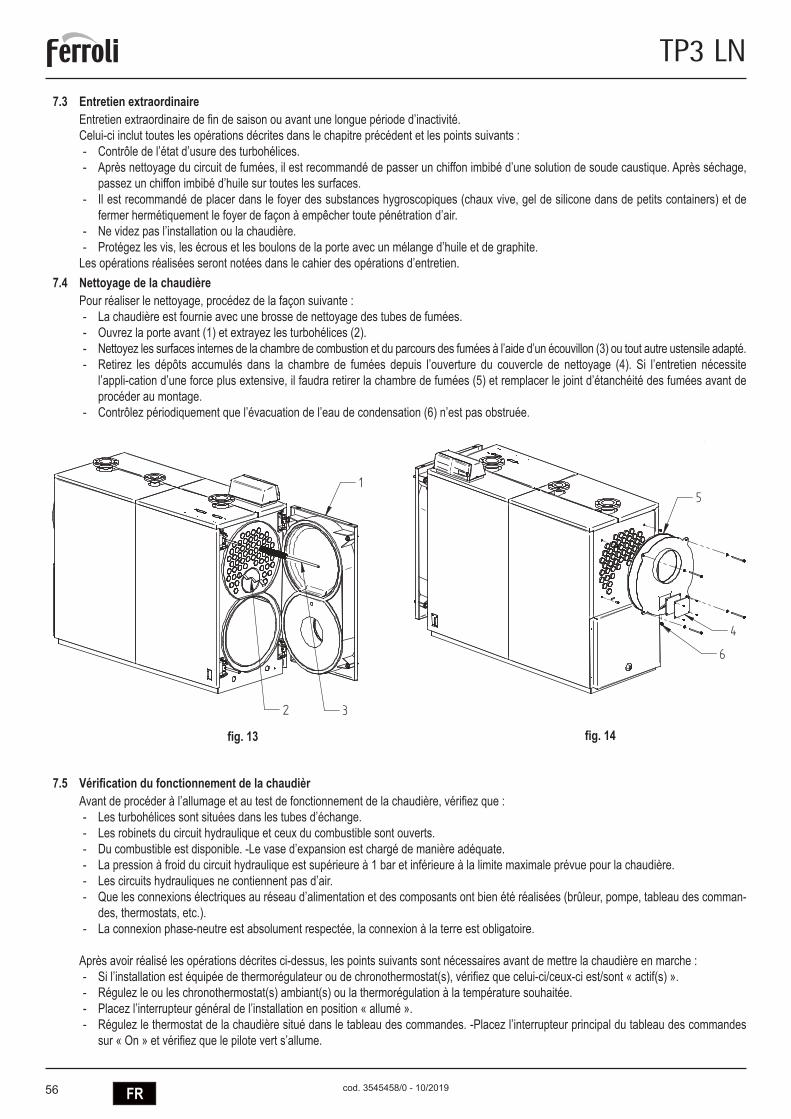
56 FR
TP3 LN
cod. 3545458/0 - 10/2019
7.3 Entretien extraordinaireEntretien extraordinaire de fin de saison ou avant une longue période d’inactivité.Celui-ci inclut toutes les opérations décrites dans le chapitre précédent et les points suivants :
- Contrôle de l’état d’usure des turbohélices. - Après nettoyage du circuit de fumées, il est recommandé de passer un chiffon imbibé d’une solution de soude caustique. Après séchage,
passez un chiffon imbibé d’huile sur toutes les surfaces. - Il est recommandé de placer dans le foyer des substances hygroscopiques (chaux vive, gel de silicone dans de petits containers) et de
fermer hermétiquement le foyer de façon à empêcher toute pénétration d’air. - Ne videz pas l’installation ou la chaudière. - Protégez les vis, les écrous et les boulons de la porte avec un mélange d’huile et de graphite.
Les opérations réalisées seront notées dans le cahier des opérations d’entretien.7.4 Nettoyage de la chaudière
Pour réaliser le nettoyage, procédez de la façon suivante : - La chaudière est fournie avec une brosse de nettoyage des tubes de fumées. - Ouvrez la porte avant (1) et extrayez les turbohélices (2). - Nettoyez les surfaces internes de la chambre de combustion et du parcours des fumées à l’aide d’un écouvillon (3) ou tout autre ustensile adapté. - Retirez les dépôts accumulés dans la chambre de fumées depuis l’ouverture du couvercle de nettoyage (4). Si l’entretien nécessite
l’appli-cation d’une force plus extensive, il faudra retirer la chambre de fumées (5) et remplacer le joint d’étanchéité des fumées avant de procéder au montage.
- Contrôlez périodiquement que l’évacuation de l’eau de condensation (6) n’est pas obstruée.
7.5 Vérification du fonctionnement de la chaudièrAvant de procéder à l’allumage et au test de fonctionnement de la chaudière, vérifiez que :
- Les turbohélices sont situées dans les tubes d’échange. - Les robinets du circuit hydraulique et ceux du combustible sont ouverts. - Du combustible est disponible. -Le vase d’expansion est chargé de manière adéquate. - La pression à froid du circuit hydraulique est supérieure à 1 bar et inférieure à la limite maximale prévue pour la chaudière. - Les circuits hydrauliques ne contiennent pas d’air. - Que les connexions électriques au réseau d’alimentation et des composants ont bien été réalisées (brûleur, pompe, tableau des comman-
des, thermostats, etc.). - La connexion phase-neutre est absolument respectée, la connexion à la terre est obligatoire.
Après avoir réalisé les opérations décrites ci-dessus, les points suivants sont nécessaires avant de mettre la chaudière en marche : - Si l’installation est équipée de thermorégulateur ou de chronothermostat(s), vérifiez que celui-ci/ceux-ci est/sont « actif(s) ». - Régulez le ou les chronothermostat(s) ambiant(s) ou la thermorégulation à la température souhaitée. - Placez l’interrupteur général de l’installation en position « allumé ». - Régulez le thermostat de la chaudière situé dans le tableau des commandes. -Placez l’interrupteur principal du tableau des commandes
sur « On » et vérifiez que le pilote vert s’allume.
fig. 13 fig. 14
5
4
6
1
32
5
4
6
1
32

57FR
TP3 LN
cod. 3545458/0 - 10/2019
La chaudière réalisera la phase d’allumage et continuera à fonctionner jusqu’à ce que les températures régulées soient atteintes. Dans le cas d’anomalies d’allumage ou de fonctionnement, la chaudière réalisera un « ARRÊT DE BLOCAGE » signalé par le pilote rouge situé sur le brûleur et la signalisation rouge du tableau des commandes. Après un tel « ARRÊT DE BLOCAGE », attendez environ 30 secondes avant de rétablir les conditions de mise en marche. Pour ce faire, appuyez sur le « bouton/pilote » du brûleur et attendez que la flamme s’allume. Si ceci ne fonctionne pas, répétez l’opération au maximum 2 ou 3 fois et vérifiez :
- Les informations figurant dans le manuel d’instructions du brûleur. - Le chapitre « VÉRIFICATION DU FONCTIONNEMENT DE LA CHAUDIÈRE ». - Les connexions prévues dans le schéma placé à proximité du tableau des commandes.
Une fois la mise en marche réalisée, il faudra vérifier que l’appareil effectue l’arrêt et la mise en marche successive. Pour ce faire : - Modifiez le réglage du thermostat de la chaudière ; - Intervenez sur l’interrupteur principal du tableau des commandes. - Intervenez sur le thermostat d’ambiance ou sur le programmateur horaire ou bien sur la thermorégulation. - Vérifiez la rotation libre et correcte des pompes. - Vérifiez l’arrêt total de la chaudière en agissant sur l’interrupteur général de l’installation.
Si toutes les conditions sont respectées, remettez l’appareil en service, contrôlez la combustion (analyse des fumées), du débit du combustible et de l’étanchéité du joint de la porte et de la chambre des fumées.
7.6 Contrôle du fonctionnement du brûleur - Consultez le manuel d’instructions du brûleur. - Suivez toutes les règles des normes locales relatives à l’entretien du brûleur.
7.7 Pannes et solutions possiblesNous allons ci-après fournir une liste contenant les indications relatives aux pannes et anomalies principales pouvant se produire lors de la gestion de la chaudière. Nous indiquerons les causes possibles ainsi que les solutions pouvant être apportées.
ANOMALIESLE GÉNÉRATEUR SE SALIT FACILEMENTCAUSE: Brûleur mal réglé SOLUTION : Contrôlez le réglage du brûleur (analyse des fumées)
Brûleur mal réglé Nettoyez le parcours des fumées et la cheminéeParcours de l’air du brûleur sale Nettoyez la volute d’air du brûleur
LE GÉNÉRATEUR NE PARVIENT PAS À AUGMENTER LA TEMPÉRATURECAUSE: Corps du générateur sale SOLUTION : Nettoyez le parcours des fumées
Union générateur/brûleur Contrôlez les données et les règlementsDébit du brûleur insuffisant Contrôlez le réglage du brûleurThermostat de réglage Contrôler le fonctionnement normal
Contrôler la température programméeLE GÉNÉRATEUR EFFECTUE UN ARRÊT DE SÉCURITÉ THERMIQUE AVEC SIGNALISATION LUMINEUSE DANS LE TABLEAU DES COMMANDESCAUSE: Thermostat de réglage SOLUTION : Contrôler le fonctionnement normal
Contrôler la température programméeContrôler le câblage électriqueVérifier les boules des sondes
Manque d’eau Contrôler la pression du circuitPrésence d’air Contrôler la soupape de purge
LE GÉNÉRATEUR CHAUFFE MAIS LE SYSTÈME DE CHAUFFAGE EST FROID CAUSE: Présence d’air dans l’installation SOLUTION : Purger l’installation
Pompe en panne Débloquez la pompeThermostat des valeurs minimales (si pré-sent)
Contrôler la température programmée
ODEURS DE PRODUITS NON BRÛLÉSCAUSE: Émission de fumées dans l’air ambiant SOLUTION : Vérifier la propreté du corps du générateur
Vérifier la propreté du conduit de fuméesVérifier l’herméticité du générateur, des conduits de fumées et de la cheminée
INTERVENTION FRÉQUENTE DE LA SOUPAPE DE SÉCURITÉCAUSE: Pression du circuit de l’installation SOLUTION : Contrôler la pression de charge
Vérifier le circuit de l’installationVérifier le réglageContrôler la température programmée
Vase d’expansion de l’installation Vérifier

58 RU
TP3 LN
cod. 3545458/0 - 10/2019
• Внимательно прочитайте предупреждения, содержащиеся внастоящемруководстве.
• После установки котла проинформируйте пользователя опринципом работы аппарата и передайте ему настоящееруководстсво; оно является существенной и неотъемлемойчастью изделия и должно быть бережно сохранено дляиспользованиявбудущем.
• Установка и техническое обслуживание должныосуществляться квалифицированными специалистамив соответствии с действующими нормативами, согласноинструкциям изготовителя и прошедшим курс обучения вспециализированномцентре.Запрещаетсявыполнятькакие-либо операции с опломбированными регулировочнымиустройствами.Запрещаетсявыполнятькакие-либоработынаопломбированныхрегулировочныхустройствах.
• Неправильная установка или ненадлежащее техническоеобслуживание могут быть причиной вреда для людей,животных и имущества Изготовитель не несет никакойответственности за ущерб, связанный с ошибочнымиустановкой и эксплуатацией аппарата, а также снесоблюдениемпредоставленныхиминструкций.
• Перед выполнением любой операции очистки илитехнического обслуживания отсоедините прибор отсетей питания с помощью главного выключателя и/илипредусмотренныхдляэтойцелиотсечныхустройств.
• В случае неисправной и/или ненормальной работыагрегата, выключите его и воздерживайтесь от любойпопытки самостоятельно отремонтировать или устранитьпричину неисправности. В таких случаях обращайтесьисключительноквалифицированномуперсоналу.Возможныеоперации по ремонту-замене комплектующих должнывыполняться только квалифицированными специалистамис использованиемисключительно оригинальных запчастейНесоблюдение всего вышеуказанного может нарушитьбезопасностьработыагрегата.
• Настоящий агрегат допускается использовать толькопо тому назначению, для которого он спроектирован и
изготовленЛюбоедругоеегоиспользованиеследуетсчитатьненадлежащими,следовательно,опасным
• Упаковочные материалы являются источникомпотенциальной опасности и не должны быть оставлены вместах,доступныхдетям.
• Не разрешается использование агрегата лицами (в томчисле,детьми)сограниченнымифизическими,сенсорнымиили умственными возможностями или лицами безнадлежащего опыта и знаний, если они не находятся поднепрерывным надзором или проинструктированы насчетправилбезопасногоиспользованияагрегата.
• Приведенные в настоящеи руководстве изображениядают упрощенное представление изделия которое можетнесущественноотличатьсяотготовогоизделия.
• �УКАЗАНИЯ�ПО�УТИЛИЗАЦИИ�ОБОРУДОВАНИЯ� Утилизация оборудования должна производиться в
специализированныхпредприятияхсогласнодействующемузаконодательству.
• УКАЗАНИЯ�ПО�ХРАНЕНИЮ�ОБОРУДОВАНИЯ Для обеспечения правильных условий хранения, строго
придерживатьсяуказаниямвруководствепоэксплуатацииимаркировкенаупаковке.Оборудованиедолжнохранитьсявзакрытомисухомпомещении,вотсутствиитокопроводящейпыли и паров химически активных веществ, разрушающихизоляциютокопроводов.Срокхранениянедолженпревышать24месяца.Поистечении24месяцевнеобходимапроверкацелостностиоборудования.
• РЕСУРС�РАБОТЫ�И�СРОК�СЛУЖБЫ� Средний срок службы зависит от условий эксплуатации,
установки и технического обслуживания. Установкаоборудования должна производиться в соответствии сдействующим законодательством, а изнашивающиесядетали должны быть своевременно заменены. Решение опрекращенииэксплуатации,списаниииутилизациипринимаетВладелецисходяизфактическогосостоянияоборудованияизатратнаремонт.Среднийсрокслужбы-10лет.
• Заводскаятабличканаходитсяназаднейсторонекотла.
Данныйсимволозначает“Осторожно”исопровождаетвсеуказания,касающиесябезопасности.Строгопридерживайтесьтакихуказанийвоизбежаниеопасностивредадляздоровьялюдейиживотныхиматериальногоущерба.
2
ModelloModel
230V - ~50 HzAlimentazione elettricaElectrical InputAlimantation éléctrique
Alimentaciòn eléctrìca
Potenza termica Nominale
l
cod. 31350492
Nominal Power Output
Portata Termica NominaleNominal Power Input kW
kW
Max Pressure Heatingbar
Max Temp. RiscaldamentoMax Temp Heating
°C
Max Press. Riscaldamento
No. MatricolaConstruction No.No.de fabrication
No.de fabricacion
Dèbit thermique nominal
Caudal tèrmico nominal
Puissance nominal
Potencia Nominal
Pression maxi ChauffagePresiòn màx. de Calefacciòn
Temperature maxi ChauffageTemper.màx.de Calefacciòn
H O
Codice PinCode
t.max safety 110°C
barPressione prova idraul./DataHidraulic test pressure/DatePression d'épreuve hydraulique/Date
Prueba presiòn hidràulica/Fecha
Заводской номер
Макс. рабочее давление
Обьем котловой воды
Опрессовочное давление/Дата
Электропитание
Код
Модель
0476/19Manufacturer address / Адрес производителя: 37047, San Bonifacio (VR), Via Ritonda 78/a
Дата производства: Смотри инструкцию
Номинальная мощность
Полезная мощность
Макс. рабочая температура
Топливо : Вид и номинальное давление газа смотрите в инструкции к горелке
Made in Italy / Сделано в Италии Данный прибор должен устанавливаться в соответствии с действующей инструкцией по монтажу и работать только в помещении с достаточной вентиляцией. Изучите инструкцию, прежде чем устанавливать прибор и вводить его в эксплуатацию. Нарушение требований инструкций по монтажу, технического обслуживания и правил эксплуатации прибора может привести к опасности возникновения пожара, взрыва, отравления угарным газом, поражения электрическим током и термического воздействия.
0476CT3148
Заводскойномер(pos.H)-ПРИМЕР:1903AC001
19 = Годвыпуска03 = ПроизводственнаянеделяAC = Линиясборки0001 = Прогрессивноечисло

59RU
TP3 LN
cod. 3545458/0 - 10/2019
1.� ПРЕДИСЛОВИЕ ........................................................................................................................................................................ 602.� ОБЩИЕ�РЕКОМЕНДАЦИИ ...................................................................................................................................................... 603.� CEPTИФИКAЦИЯ ...................................................................................................................................................................... 604.� ТЕХНИЧЕСКИЕ�И�ПРОИЗВОДСТВЕННЫЕ�ХАРАКТЕРИСТИКИ,�РАЗМЕРЫ ..................................................................... 604.1 Описаниекотлоагрегата............................................................................................................................................................................ 60
4.2 Принципработы......................................................................................................................................................................................... 61
4.3 Техническиепоказатели-размеры-гидравлическиесоединения........................................................................................................ 62
4.4 Идентификация.......................................................................................................................................................................................... 63
5.� МОНТАЖ .................................................................................................................................................................................... 635.1 Упаковка...................................................................................................................................................................................................... 63
5.2 Погрузка/разгрузка..................................................................................................................................................................................... 63
5.3 Помещениекотельной(рис.5).................................................................................................................................................................. 64
5.4 Удалениепродуктовсгорания(рис.6)...................................................................................................................................................... 65
5.5 Гидравлическиеподключения................................................................................................................................................................... 65
5.5.1 Питательнаявода................................................................................................................................................................................. 65
5.5.2 Патрубкиподачи/возвратасистемыотопления................................................................................................................................. 65
5.5.3 Системанаполнения/дренажа............................................................................................................................................................ 65
5.5.4 Подключениерасширительногобакаипредохранительногоклапана............................................................................................ 66
5.5.5 Рециркуляционныйнасос(рис.7)....................................................................................................................................................... 66
5.6 Открытиеирегулировкапереднейдвери................................................................................................................................................ 66
5.7 Монтажгорелки(рис.9)............................................................................................................................................................................. 67
5.8 Установкаглазкаконтроляпламени(рис.10)......................................................................................................................................... 68
5.9 Монтажпанелейобшивки,модели92÷190.............................................................................................................................................. 68
5.10 Монтажпанелейобшивки,модели240÷2360.......................................................................................................................................... 69
6.� ВВОД�В�ЭКСПЛУАТАЦИЮ ....................................................................................................................................................... 706.1 Предварительныепроверки...................................................................................................................................................................... 70
6.2 Первыйзапуск............................................................................................................................................................................................ 70
6.3 Остановкакотла......................................................................................................................................................................................... 70
7.� OБCЛУЖИBAHИE ..................................................................................................................................................................... 707.1 Общиеуказания......................................................................................................................................................................................... 70
7.2 Текущееобслуживание............................................................................................................................................................................. 70
7.3 Специальноеобслуживание..................................................................................................................................................................... 71
7.4 Чисткакотла.............................................................................................................................................................................................. 71
7.5 Проверкаработоспособностикотла......................................................................................................................................................... 71
7.6 Диагностикаработыгорелки..................................................................................................................................................................... 72
7.7 Устранениенеисправностей..................................................................................................................................................................... 72

60 RU
TP3 LN
cod. 3545458/0 - 10/2019
1. ПРЕДИСЛОВИЕУважаемый покупатель,благодарим вас за покупку котла PREXTHERM� RSW� N. Это руководство специально подготовлено длятого, чтобы ознакомить вас с информацией,мерами предосторожности и рекомендациями помонтажу, правильной эксплуатациии техническому обслуживанию котла.Пожалуйста, прочтите его внимательно и сохраните для использования в дальнейшем. Мысоветуемвамвнимательноознакомитьсяссодержаниемданногоруководства,чтобыиспользоватьэтовысококачественноеизделиемаксимальноэффективно.Несоблюдениерекомендацийиуказаний,содержащихсявданномруководстве,освобождаетизготовителяотлюбойответственностиианнулируетгарантию.
2. ОБЩИЕ�РЕКОМЕНДАЦИИ - Эторуководствоявляетсянеотъемлемойчастьюизделияипредоставляетважныерекомендациипомонтажу,уходуитехническомуобслуживанию.
- Данноеизделиедопускаетсякиспользованиюисключительнопопрямомуназначению. - Данное�изделие�предназначено�для�нагрева�воды�до� температуры�ниже� точки� кипения�и�должно�быть�подключено� к�системе�центрального�отопления�и/или�системе�бытового�горячего�водоснабжения,�в�соответствии�с�его�характеристиками,�особенностями�и�тепловой�мощностью.
- Передпроведениеммонтажныхработубедитесьвтом,чтокотелнебылповрежденвовремяпогрузки/разгрузкиитранспортировки. - Котелдолженбытьустановленнанегорючемосновании. - Котелдолженбытьустановленнарасстоянииболее100ммотлюбогогорючегоматериалаилиегокомпонента. - Установкакотладолжнапроизводитьсяквалифицированнымперсоналомивсоответствиисдействующиминормами. - Передпроведениемлюбыхработпочисткеилиобслуживаниюкотла,отключитеегоотсетипитания. - ПРОИЗВОДИТЕЛЬненесетникакойответственностизаущерб,причиненныйлюдями/иливещамиз-заошибокприустановке,нaлaдкe,обслуживанииинеправильнойэксплуатации.
- Котелисоответствующееоборудованиедолжныбытьвведенывэксплуатациюуполномоченнымперсоналом. - Вовремявводавэксплуатациюнеобходимоубедитьсявправильностиработывсехустройстврегулированияиконтроля. - Вслучаедлительногопериодапростояоборудованиядляегозапусканеобходимопривлечениеквалифицированногоперсонала.
НормыМонтажоборудованиядолженвыполнятьсяприсоблюдениидействующихместныхнормповыборуиподготовкеплощадкиподустановкукотла,пообеспечениюнеобходимыхусловийвентиляции,поподдержаниюштуцеров,дымовойтрубыитопливныхтрубопроводоввидеальномсостоянии,побезопасностиэлектрическихсистем,атакжевсехдругихдействующихправилбезопасностииохранытруда.Гарантийные�обязательстваГарантийныеобязательстваявляютсядействительнымитолькоприусловиисоблюдениявсехнормирекомендаций,содержащихсявданномруководстве.Несоблюдениенормиприведенныхрекомендацийлишаетправанагарантийнуюподдержку.Гарантиянераспространяетсянаслучаиповреждениякотлаврезультатевоздействиякислотногоконденсатапродуктовсгоранияилиотложениянакипиврезультатеиспользованияжесткойилиагрессивнойводы,посколькуданныеповрежденияявляютсяследствиемэксплуатацииоборудования.
3. CEPTИФИКAЦИЯ
Маркировка� CE� подтверждает,� что� изделие� соответствует� основным� требованиям� правил� GAR� и� других� действующих� директив.�Декларация�о�соответствии�может�быть�предоставлена�производителем.
ИДЕНТИФИКАЦИОННЫЕ�КОДЫ�ИЗДЕЛИЙTP3 LN 70 ORD099XA TP3 LN 320 ORD600XA TP3 LN 940 ORDG00XATP3 LN 92 ORD000XA TP3 LN 401 ORD800XA TP3 LN 1060 ORDH00XATP3 LN 107 ORD100XA TP3 LN 500 ORDB00XA TP3 LN 1250 ORDJ00XATP3 LN 152 ORD200XA TP3 LN 600 ORDD00XA TP3 LN 1480 ORDL00XATP3 LN 190 ORD300XA TP3 LN 720 ORDE00XA TP3 LN 1890 ORDP00XATP3 LN 240 ORD400XA TP3 LN 820 ORDF00XA TP3 LN 2360 ORDS00XA
СТРАНЫ�НАЗНАЧЕНИЯ:�ES�-�IT�-�FR�-�RU
4. ТЕХНИЧЕСКИЕ�И�ПРОИЗВОДСТВЕННЫЕ�ХАРАКТЕРИСТИКИ,�РАЗМЕРЫ4.1 Описание�котлоагрегата
КонструкциякотловсерииTP3�LNгарантируетвысокуютепловуюмощностьиэффективностьпринизкойтемпературеуходящихгазов,обеспечивая,такимобразом,низкуюэмиссиювредныхвыбросов.Оборудованиепроизведеновсоответствиисостандартом303EN,часть1.Основнымиотличительнымиособенностямиконструкцииявляются:- тщательное проектирование поверхностей, которое обеспечивает оптимальное соотношение между oбъeмaми сгорания и
теплообменнымиповерхностями- правильныйвыбориспользуемыхматериалов,чтовлияетнадолгийсрокслужбыкотла.

61RU
TP3 LN
cod. 3545458/0 - 10/2019
Отличительной чертой трехходовых котлов является газоплотное сгорание, двойная наружная наложенная отделка, полностьюохлаждаемаявнижнейчастигорелкаитрубныйпучоквнижнейчасти,оснащенныйтурбулизаторами(завихрителями)создающимивращающийся поток, который интенсифицирует конвективный теплообмен. Покидая трубный пучок, уходящие газы поступают взаднююкамеру–дымовойколлекторидалеепоступаютвдымовуютрубу.Котлыоборудованыпереднимидверками,оснащеннымипетлями,которыепозволяютизменятьсторонуоткрытиякотланаправуюилилевую,атакжерегулируютсяповысотеиглубине.Корпускотлаизолировантолстымлистомстекловаты,покрытойизносостойкимматериалом.Наружнаяотделкакотласостоитизокрашенныхпорошковым способом стальных панелей. Транспортировочные проушины располагаются сверху корпуса. Котел оснащен двумя1/2”штуцерамидля колодок сигнальныхлампочек (каждаяна трилампочки).Панель управления с предварительно выполненнойэлектропроводкой(заказываетсяотдельно)находитсянадкотломиобеспечиваетавтоматическуюработукотла.
4.2 Принцип�работыКотлы ТР3� LN оборудованы полностью охлаждаемой закрытой цилиндрической горелкой, в которой находится первый газоход,возвратнойтрубойбольшогодиаметра(2-ойгазоход)итрубнымпучком,расположеннымвверхнейчасти(3-ийгазоход).Навыходеизтрубныхпучковгазысобираютсявдымовойколлекториоттудауходятвдымовуютрубу.Камерасгораниявсегдаявляетсягерметичнойигазоплотнойприработегорелки.Дляопределенияизбыточногодавления,см.таблицынастр.106,подколонкойАэродинамическоесопротивлениепогазовомутракту.Дымоходыиихподключениядолжныбытьвыполненывсоответствиисдействующимистандартамии нормами, с использованием жестких газоходов, устойчивых к воздействию высоких температур, конденсата, механическихвоздействийиобладающихгазоплотностью(Рис.1).
Обозначения1 Пультуправления T2Возвратводы2Монтажнаяплитадлягорелки T3 Присоединениерасширительногобака3 Люкчисткидымовогоколлектора T4 Слив/дренажкотла4Окошкоконтроляпламени T5ПрисоединениедымовойтрубыT1 Подачаводы T6 Присоединениегорелки
3
T3T1T2
T4
T5
F B E
P
L1 R
I
T1-T3-T2
A
Q
CD
H
T6
1
T1-T3-T2
T4
T5
2
4
LG
M
0694
ModelloModel
230V - ~50 Hz
Elektrisk forsyning
Alimentazione elettricaElectrical InputAlimantation éléctriqueAlimentaciòn eléctrìca
ktrnhjgbnfybt
StromspannungStroomspanningAlimentacao elèctricaIngaende spanning
Potenza termica Nominale
l
cod. 313504
91
Nominal Power Output
Portata Termica NominaleNominal Power Input
kW
kW
Max Pressure Heatingbar
Max Temp. RiscaldamentoMax Temp Heating
°C
Max Press. Riscaldamento
No. MatricolaConstruction No.
Konstruktions-nr.Herstellnr.
NennwarmeleistungNominal warmtevermogen
NennheizwertNominaal verwarmingsvermogen
Max. WasserdruckMax. waterdruk
Max. KesseltemperaturMax. Ketelstemperatuur
Fabrikaatnr.No.de fabricationNo de construccaoValmistusnumeroPfdjlcrjq yjvthNo.de fabricacion
Dèbito tèrmico nominalDèbit thermique nominalNominell varmetillforselCaudal tèrmico nominal NtgkjghjbpdjlbntkmyjcnmNominel termisk forsyning
Puissance nominal Potencia NominalPotencia Nominal Nomineel effektNominel Kraft GjktpyfzNtgkjdfzvjoyjcnm
Pression maxi Chauffage Pressao màx. de caldeiraPresiòn màx. de Calefacciòn Max tryckVarmeanlaegets maks.-tryk Vfrc=hf,jxttlfdktybt
Temperature maxi Chauffage Temperatura màx. de caldeiraTemper.màx.de Calefacciòn Max varmartemperaturVarmeanlaegets maks.-temperatur Vfrc=hf,jxfzntvgthfnehf
H O
Codice PinCode
t.max safety 114°C
bar
Pressione prova idraul./DataHidraulic test pressure/DatePre ssi on d'é pre uve hy dra uli que /Da tePrueba presiòn hidràulica/FechaDruck wasserdruckprÜfung/Datum
Vandtrykprøve/DatoWaterdrukproef/DatumPressÃo do teste hidràulico/DataHydrauliskt testtryck/DatumJghtccjdjxyjtlfdkt ybt #Lfnf
VIA RI TON DA 78/ A - 37 047 SA N B ONI FACIO - V R - IT ALY
Vjltkm
Rjl
J,mtvrjnkjdjqdjls
'
35450
51/1
MANDATADEPARTVORLAUFFLOWAANVOER
RITORNORETOURRUCKLAUFRETURN
35409
07/2
35409
08/2
ATTENZIONE35451110
ATTENTION
Prima di accendere il bruciatoreassicurarsi della tenuta del portelloneonde evitare di rovinare la guarnizione. Per la regolazione e l'apertura del portellone vedere libretto istruzioni.
Before firing the burner please check the gas-side tightness onto the ceramic fiber rope of the front door. For door hinges adjustment see instruction book.
ACHTUN G - Ei n mogl icher Splat zwisch en Bre nnerro hr und fe uerfes ter au skleidung is t mit kerami kfaser es Sei l ab zuschl iessen .
OPGELE T - De mogel ijke spleet tussen brand erpijp en br anderp laat m et hittebest endig koord afluit en.
ATTENT ION - L'inte rstice event uel en tre la tete du bru leur et le re veteme nt refactair e doit etre rempli par u n co rdon e n fibr e ceramique.
ATTENZ IONE - Chiud ere con un c ordone di fi bra ce ramica l' eventu ale fe ssura tra il canot to del bruci atore e il fo ro esi stente sulla porta .
CAUTIO N - Th e even tual gap bet ween b urner head a nd re fracto ry lin ing must be sealed by a cerami c fibe r ro pe.
cod.35450482
ON
рис.�2
рис.�1

62 RU
TP3 LN
cod. 3545458/0 - 10/2019
4.3 Технические�показатели�-�размеры�-�гидравлические�соединения
TP3�LN 70 92 107 152 190 240 320 401 500
Номинальная�мощностьмин. kW 46 60 70 100 137 160 196 260 341макс. kW 70 92 107 152 190 240 320 401 500
Топочная�мощностьмин. kW 48 62,7 73,2 104,7 143,8 167,8 205,2 271,5 354,6макс. kW 73,9 97,1 112,9 160,5 200,8 252,9 335,7 419,4 522,8
Потеря�напора�воды ∆t 15°C мбар 6 6 12 7 10 17 23 22 28Потеря�напора�дыма мбар 0,54 0,89 1,2 1,65 1,8 2,4 3,3 4,4 5,43Выход�дыма* кг/час 119 156 182 258 321 405 539 670 838Макс.�рабочее�давление** бар 6 6 6 6 6 6 6 6 6Сухой�вес� стандарт�6�бар кг 236 236 332 332 460 524 833 833 1146
РАЗМЕРЫ
A mm 670 670 670 670 760 760 820 820 855B mm 770 770 1190 1190 1190 1390 1590 1590 1990C mm 1116 1116 1116 1116 1271 1271 1456 1456 1546D mm 165 165 165 165 165 165 165 165 165E mm 146 146 146 146 165 165 184 184 184F mm 152 152 152 152 152 152 152 152 152G mm 880 880 880 880 985 985 1140 1140 1225H mm 390 390 390 390 420 420 460 460 480I mm 1130 1130 1555 1555 1570 1770 1990 1990 2390M mm 160 160 160 160 145 145 160 160 155
ПОДКЛЮЧЕНИЯ
подача T1 2” 1/2 2” 1/2 2” 1/2 2” 1/2 2” 1/2 2” 1/2 DN 80 DN 80 DN 100возврат T1 2” 1/2 2” 1/2 2” 1/2 2” 1/2 2” 1/2 2” 1/2 DN 80 DN 80 DN 100приборы безопасности T3 1” 1/2 1” 1/2 1” 1/2 1” 1/2 1” 1/2 1” 1/2 DN 50 DN 50 DN 65слив T4 3/4” 3/4” 3/4” 3/4” 3/4” 3/4” 3/4” 3/4” 3/4”выход дыма T5 Ø мм 160 160 160 160 220 220 250 250 300подключение горелки T6 Ø мм 145 145 145 150 150 150 240 240 240дл. мин/макс. гнезда T6 250/320 250/320 250/320 250/320 250/320 250/320 250/320 290/360 290/360
TP3�LN 600 720 820 940 1060 1250 1480 1890 2360
Номинальная�мощностьмин. kW 390 468 533 611 689 813 962 1229 1535макс. kW 600 720 820 940 1060 1250 1480 1890 2360
Топочная�мощностьмин. kW 403,8 484,8 552,3 633,4 714,5 843,7 999,1 1278,1 1598,9макс. kW 627,2 752,5 856,7 981,6 1106,3 1303,6 1542,0 1919,3 2449,8
Потеря�напора�воды ∆t 15°C мбар 18 25 25 33 40 55 45 70 65Потеря�напора�дыма мбар 6,2 5,9 6,7 6,3 7,2 7 7,4 7,2 7,8Выход�дыма* кг/час 1005 1207 1376 1574 1774 2088 2474 3091 3947Макс.�рабочее�давление** бар 6 6 6 6 6 6 6 6 6Сухой�вес� стандарт�6�бар кг 1146 1557 1584 2329 2329 2601 2871 3552 4041
РАЗМЕРЫ
A mm 855 990 990 1150 1150 1180 1180 1340 1340B mm 1990 1944 1944 2394 2394 2594 2894 2698 2998C mm 1546 1791 1791 2021 2021 2021 2021 2371 2371D mm 165 165 165 165 165 165 165 165 165E mm 184 184 184 206 206 206 206 206 206F mm 152 212 212 212 212 212 212 212 212G mm 1225 1395 1395 1625 1625 1605 1605 1920 1920H mm 480 530 530 600 600 575 575 670 670I mm 2390 2410 2410 2880 2880 3080 3380 3180 3480M mm 1615 1860 1860 2100 2100 2100 2100 2440 2440
ПОДКЛЮЧЕНИЯ
подача T1 DN 100 DN 125 DN 125 DN 150 DN 150 DN 150 DN 150 DN 200 DN 200возврат T1 DN 100 DN 125 DN 125 DN 150 DN 150 DN 150 DN 150 DN 200 DN 200приборы безопасности T3 DN 65 DN 80 DN 80 DN 100 DN 100 DN 100 DN 100 DN 125 DN 125слив T4 3/4” 3/4” 3/4” 1” 1/2 1” 1/2 1” 1/2 1” 1/2 1” 1/2 1” 1/2выход дыма T5 Ø мм 300 350 350 400 400 450 450 500 500подключение горелки T6 Ø мм 210 210 270 270 270 270 350 350 350дл. мин/макс. гнезда T6 320/390 320/390 320/390 320/390 340/410 340/410 340/410 340/470 350/480
* Топливомазут:CO2=13%-Топливогаз:CO2=10%

63RU
TP3 LN
cod. 3545458/0 - 10/2019
4.4 Идентификация Котелможетбытьидентифицированпо:-�Пакету�документов�(1)которыйимеетсянапереднейдвериисодержит: ТЕХНИЧЕСКОЕРУКОВОДСТВО ГАРАНТИЙНЫЙСЕРТИФИКАТНАКЛЕЙКИСОШТРИХКОДАМИШИЛЬДИКСВИДЕТЕЛЬСТВОПРИЕМКИ (подтверждающее,чтогидравлическоеиспытаниебыловыполнено)
-�Шильдику�(2)которыйсодержиттехническиехарактеристикииусловияприменения.ОнпоставляетсявпакетедокументовиДОЛЖЕНБЫТЬПРИКРЕПЛЕНмонтажником,послеокончаниямонтажаустановки,навидимомместевверхнейчастиоднойизбоковыхпанелейобшивки.Еслишильдикутерян,обратитесьвСлужбуТехническойПоддержкиFerroliдляполучениядубликата.
Исправление или удаление или отсутствие шильдика или других документов,затрудняющие идентификацию установки, вызывает проблемы во времяустановкииобслуживания.
5. МОНТАЖ5.1 Упаковка
КотлыTP3�LNпоставляютсявкомплектесустановленнымлюкомидымовойкамерой,атакжеизоляциейкорпуса,обшивкапоставляетсявкартоннойупаковке(Рис.2).Инструментальнаяпанель(заказываетсяотдельно) поставляется в картонной коробке, которая размещена вкамересгорания.
5.2 РазгрузкaКотел TP3� LN оборудован рым-болтами для разгрузки. Убедитесь,чтоиспользуемыестроповочныеприспособлениясоответствуютвесуподнимаемого груза. Перед установкой котла удалите деревянныеподставкипутемоткручиваниявинтовкрепления(Рис.4).
рис.�3
1
2
0694
ModelloModel
230V - ~50 Hz
Elektrisk forsyning
Alimentazione elettricaElectrical InputAlimantation éléctriqueAlimentaciòn eléctrìca
StromspannungStroomspanningAlimentacao elèctricaIngaende spanning
Potenza termica Nominale
l
cod. 31350491
Nominal Power Output
Portata Termica NominaleNominal Power Input
kW
kW
Max Pressure Heatingbar
Max Temp. RiscaldamentoMax Temp Heating
°C
Max Press. Riscaldamento
No. MatricolaConstruction No.
Konstruktions-nr.Herstellnr.
NennwarmeleistungNominal warmtevermogen
NennheizwertNominaal verwarmingsvermogen
Max. WasserdruckMax. waterdruk
Max. KesseltemperaturMax. Ketelstemperatuur
Fabrikaatnr.No.de fabricationNo de construccaoValmistusnumero
No.de fabricacion
Dèbito tèrmico nominalDèbit thermique nominalNominell varmetillforselCaudal tèrmico nominal
Nominel termisk forsyning
Puissance nominal Potencia NominalPotencia Nominal Nomineel effektNominel Kraft
Pression maxi Chauffage Pressao màx. de caldeiraPresiòn màx. de Calefacciòn Max tryckVarmeanlaegets maks.-tryk
Temperature maxi Chauffage Temperatura màx. de caldeiraTemper.màx.de Calefacciòn Max varmartemperaturVarmeanlaegets maks.-temperatur
H O
Codice PinCode
t.max safety 114°C
bar
Pressione prova idraul./DataHidraulic test pressure/DatePression d'épreuve hydraulique/DatePrueba presiòn hidràulica/FechaDruck wasserdruckprÜfung/Datum
Vandtrykprøve/DatoWaterdrukproef/DatumPressÃo do teste hidràulico/DataHydrauliskt testtryck/Datum
VIA RITONDA 78/A - 37047 SAN BONIFACIO - VR - ITALY
Заводской номер
Теплопроизводительность
Полезная Тепловаямошность
Макс. рабочее давление
Макс. рабочее температура
Обьем котловой воды
Опрессовочное давление/Дата
Электропитание
Код
Модель
2
1
рис.�4

64 RU
TP3 LN
cod. 3545458/0 - 10/2019
5.3 Помещение�котельной�(Рис.�5)КотелTP3�LN может быть установлен только в помещение, приспособленноедля этойцели, при соблюдении технических норми действующих правил, и оснащенное соответствующими вентиляционными проемами. Вентиляционные проемы должны бытьстационарными, непосредственно выходящими наружу и должны располагаться одновременно вверху и внизу котельной, всоответствиисдействующимистандартами.Расположениевентиляционныхпроемов,топливоподачи,силовойцепиисетиосвещениядолжнысоответствоватьдействующимнормамиотвечатьтипамиспользуемоготоплива.Дляоблегчениячисткисистемыгазоходов,спередикотладолжнобытьоставленосвободноепространстводлинойнеменеедлиныкорпусакотла,но,влюбомслучае,неменее,чем1300мм,приусловии,чторасстояниемеждуоткрытойна90°дверьюисоседнейстеной (Х)будетнеменеедлиныгорелки.Площадка под установку котла должна быть абсолютна горизонтальной. Следует использовать плоский бетонный фундамент,способныйвыдержатьполныйвескотлаплюсвесполногообъемаводы;дляопределенияразмеровфундаментасм.расстоянияRxQ(таблицаразмеров).Еслигорелкапоставляетсядлягаза,удельныйвескотороготяжелеевоздуха,электрическиечастидолжнырасполагатьсянениже,чемна500ммотпола.Устройствонеможетбытьустановленоснаружи,таккакононеспроектированодлянаружнойустановкиинеоснащеноавтоматическойсистемойпротивообледенения.
МОНТАЖДЛЯСТАРЫХСИСТЕМИЛИРЕКОНСТРУИРУЕМЫХСИСТЕМВслучаеустановкикотлавстарыхсистемахилиреконструируемыхсистемах,убедитесь,что:
- Дымоходсоответствуеттемпературепродуктовсгорания,рассчитаниизготовленссоблюдениемвсехдействующихнорм,такихкакминимальнаякривизна,газоплотность,теплоизоляция,инезагроможденилизакоксован.
- Электрическаяразводкавыполненавстрогомсоответствиисдействующимисоответствующимиправиламиквалифицированнымперсоналом.
- Системаподачитопливаивсебакивыполненывсоответствиисдействующимисоответствующиминормамииправилами. - Расширительныйбак/бакимогутполностьюкомпенсироватьрасширениетеплоносителя,содержащегосявсистеме. - Производительность,напоринаправлениеподачициркуляционныхнасосов–выбраныправильно. - Системапромыта,прочищенаототложений,загрязнений,продутаиопрессована. - Система водоподготовки готова обеспечить специальные требования для питательной/подпитывающей воды (см справочныевеличины).
600
600
1000
X
1000
рис.�5

65RU
TP3 LN
cod. 3545458/0 - 10/2019
5.4 Удаление�продуктов�сгорания�(Рис.�6)Дымоход и подключение газохода должны выполняться в строгом соответствиис действующими нормами и правилами, с использованием жестких газоходов,устойчивых к воздействию высоких температур, конденсата и механическихвоздействий, а также являющихся газоплотными. Дымоход должен обеспечиватьминимальноеразряжение(тягу)требуемоедействующимиправилами,подразумеваяпод «нулевым» давлением точку подключения к дымоходу. Несоответствие илинеправильный выбор размеров дымоходов может привести к увеличению шумаобразующегосявпроцессесгорания,появлениипроблемсобразованиемконденсатаинегативнымвлияниемнапараметрыпроцессасгорания.Неизолированныедымоходыявляютсяисточникомпотенциальнойопасности.Герметизациясоединенийдолжнавыполняться с применением материалов, способных выдерживать температурынеменее 250°С.Соответствующие точки измерения температуры газов и отборапробпродуктовсгораниядолжныбытьпредусмотренымеждукотломидымоходом.Поперечноесечениеидлинадымовойтрубыдолжнывыбиратьсявсоответствиисдействующиминациональнымииместнымиправилами.
ВНИМАНИЕ: из-за низкой температуры дыма внутри дымохода можетобразоватьсяконденсат.
5.5 Гидравлические�подключения5.5.1 Питательная�вод
Химические свойства питательной и подпитывающей воды являютсяопределяющими для правильной и безопасной эксплуатации котла. Водадолжна быть подготовлена с применением соответствующих систем.Величины,указанныенижевтаблицемогутиспользоватьсякаксправочные.
ОБЩАЯЖЕСТКОСТЬAppm10ЩЕЛОЧНОСТЬмг/лCaCO3750PH8÷9КРЕМНИЙppm100ХЛОРИДЫppm3500
Прииспользованииводывсистемахцентральногоотопленияводадолжнаподготавливатьсявследующихслучаях:- Оченьбольшиесистемы.- Оченьжесткаявода.- Частаяподпиткасистемыводой.
В этих случаях, если система нуждается в частичном или полном опорожнении, то она должна быть заполнена подготовленнойводой.Дляконтроляводысавтоматическойподпиткой,необходимаустановкачасовогорасходомера.Наиболеераспространеннымиявлениями,возникающимивсистемахотопления,являются:
- Отложениянакипи Образование накипи обычно выше там, где выше температура стенок. Из-за ее низкой теплопроводности, отложения накипи
снижаюттеплообменнастолько,чтодажепритолщиневнесколькомиллиметровтеплообменмеждудымовымигазамииводойограничивается,вызываяперегревчастей,обращенныхкпламениисоответственноразрушение(трещины)натрубныхдосках.
- Коррозияповодянойстороне Коррозия металлических поверхностей по водяной стороне котла возникает из-за диссоциации железа в его ионы. Наличие
растворенных газов, в частности кислорода и углекислого газа, играют важную роль в этом процессе. Умягченная и/илидеминерализованнаяводапрепятствуютобразованиюнакипиидругихотложений,однаконепредотвращаюткоррозии.Поэтомуводадолжнабытьобработанаингибиторамикоррозии.
5.5.2 Трубы�подачи/возврата�в�системах�центрального�отопленияДиаметры подающих и обратных патрубков указаны для каждой модели котла в таблице РАЗМЕРЫ. Убедитесь, что системаоборудованадостаточнымколичествомвоздухоотводчиков.Патрубкикотланедолжнынестинагрузкуотвесаприсоединенныхтрубсистемы,азначитдолжныбытьустановленыспециальныеопоры.
5.5.3 Система�наполнения/дренажаДлянаполненияисливакотлакрандолженбытьприсоединенкпатрубкуТ4сзадикотла(см.рисунокРАЗМЕРЫ).
рис.�6

66 RU
TP3 LN
cod. 3545458/0 - 10/2019
5.5.4 Расширительные�баки�и�подключение�предохранительных�клапаноКотлыTP3LNпредназначеныдляэксплуатациивсистемахспринудительнойциркуляцией,каксоткрытыми,такисзакрытымирасширительнымибаками.Установкарасширительногобакавсегданеобходимадлякомпенсациитепловогорасширенияводы.Впервомслучаевысотаводяногостолбадолжнабыть,покрайнеймере,на3метравышеобшивкикотлаибакдолжениметьдостаточнуюемкость(междууровнемводывнемипереливнойтрубой),дляувеличенияобъемаводывсейсистемыврезультатенагрева.Высокиеиузкиерасширительныебакиболеепредпочтительны,посколькуониобеспечиваютминимальныйконтактмеждуводнойповерхностьюиатмосферой,понижая,такимобразом,испарение.Вовторомслучае,емкостьзакрытогорасширительногобакадолжнабытьрассчитана,принимаявовнимание:- общийобъемводы,находящийсявсистеме- максимальноерабочеедавлениевсистеме- максимальноерабочеедавлениерасширительногобака- предустановленноедавлениеврасширительномбакеРасширительныйбакподключаетсяксистеметрубами.Этитрубы,подключающиесякпатрубкуТ3(смтаблицуРАЗМЕРЫ),недолжныоборудоватьсязапорнымикранами.НапатрубкеТ3илинапатрубкеподачи,нарасстоянии0,5мотпервогофланца,устанавливается предохранительный клапан, размеры которого определяются в соответствии с действующими местныминормамиимощностьюкотла.Недопускаетсяустанавливатькакую-либозапорнуюарматурумеждукотломирасширительнымбакомимеждукотломипредохранительнымиклапанами,которыедолжныбытьотрегулированынадавление,непревышающеемаксимальноедопустимоерабочеедавление.
5.5.5 Рециркуляционный�насос�(Рис.�7)Конденсацияводяныхпаров,содержащихсявдымовыхгазах,покидающихкотел(конденсат) появляется тогда, когда тепература воды в обратной магистралистановится меньше 55°С и является довольно значительной, особенно призапускекотлаутром,посленочногопростоя.Этотконденсатявляетсякислотнымиобладаеткоррозионнымэффектом,и,стечениемвремени,воздействуетнаметаллкотла.Следовательно,сцельюпредотвращенияконденсациимеждуподающимиобратным патрубками следует установить рециркуляционный насос для работыс любым смесительным клапаном. При работающей системе насос долженобеспечиватьрасходвпределах20и30%отобщегорасхода;он такжедолженобеспечиватьтемпературунаобратномпатрубкенениже55°Спринизкомнапоре,которыйопределяетсятолькопреодолениемсопротивлениякотлаиклапанов.Длятого,чтобыизмеритьэффективнуютемпературунаобратноймагистралисистемыцентрального отопления, с целью управления рециркуляционным насосом иливоздействия на его функционирование для получения стабильной температурысистемы,штуцер зонда должен быть расположен на расстоянии эквивалентном3-5диаметрамобратноготрубопроводапротивтеченияотместастыковки.
5.6 Открытие�и�регулировка�передней�двериЛюкоснащендвумяскобами(поз.3)иодинаковымипетлями.- ДляопределениянаправленияоткрытияВПРАВОилиВЛЕВОотвернитегайку(поз.7),отвернитеиснимитегайку(поз.6)правую
илилевую,задаваянаправлениеоткрытиялюка.- Регулировкалюкаповысотепроизводитсяприпомощигайки(поз.2),послезавершениярегулировкизаблокируйтевинты(поз.1).- Продольнаярегулировкапроизводитсяприпомощивинта(поз.8).
Обозначения(рис.8)1 Фиксирующийвинт2 Гайкафиксации/регулировкилюка3 Скобапетли4 Осьпетли5 Винтпетли6 Гайкафиксациипетли7 Фиксирующийвинт8 Винтыигайкификсации/регулировкискобыпетли
рис.�7

67RU
TP3 LN
cod. 3545458/0 - 10/2019
5.7 Монтаж�горелки�(Рис.�9)
Монтаж горелкинадверькотладолженобеспечиватьабсолютнуюгазоплотностьдляпродуктовсгорания.Послемонтажа горелкинакотел,зазормеждугнездомгорелкииогнеупорнымматериаломнадверидолженбытьзаполненслоемкерамическогошнура(А),поставляемогоскотлом.Этопредотвращаетдверьотперегреваи,какследствие,отостаточнойдеформации.Подключенияподачитопливакгорелкедолжнырасполагатьсятак,чтобыпозволятьполноеоткрытиедверикотласустановленнойгорелкой.
модели Lмин.(мм) Lмакс.(мм)70-152 230 300190-240 250 320320-401 290 360500-600 320 390720-820 320 390940-1060 340 4101250-1480 340 4701890-2360 350 480
123
5
6
7
8
8
4
рис.�8
L
A
рис.�9

68 RU
TP3 LN
cod. 3545458/0 - 10/2019
5.8 Установка�глазка�контроля�пламени�(Рис.�10)Глазок для визуального контроля пламени оснащается герметичнымсоединением(1),котороедолжноподключатьсясиликоновойилимеднойтрубкой к выходу на горелке (2). Такая конструкция позволяет воздуху,поступающемуотвентиляторагорелкиохлаждатьстеклоипредотвращаетегоотзакопчивания.Неисправностьприсоединениятрубкикглазкуможетвызватьполомкуглазка.НагревательныеустановкиFerroliмогутиметьконфигурацию,отличнуюотприведенныхвыше,всвязистем,чтовседополнениябылиразработанывнашейкомпанииипрошлилабораторныеиспытания.
5.9 Установка�панелей�обшивки,�модели�92-190Последовательностьмонтажа(рис.11)a) Установитебоковыеправыеилевыепанели(поз.1-2)закрепивихнадержателе(поз.13).Дляопределениякакаяизсторонправая
илилеваяобратитевниманиенаотверстиевпластинедляпроводкикабелей(поз.6),онадолжнабытьповернутавпереднююсторонукотла.
б) закрепитепанельуправлениянаверхнююпанель(поз.3).в) Установитеверхнююправуюпанель(поз.б)спанельюуправлениянабоковуюпанель(поз.1)вместеспружиной,перекладинами
игайками(поз.10-11-12).г) Вставьтевчехлыколбыдатчиков,какпоказанонарис.20ипроизведитеэлектрическоеподключениепанелиуправленияклинии
питания,горелке,насосуит.д.Рекомендуетсявставитьдатчикидоупоравсоответствующиеколодцы,обеспечивихконтакт.Затемзакрепитепружинками.Закройтекрышкуэлектрощита,проведитевилкугорелкичерезбоковуюпластину(поз.6)изаблокируйтекабельприпомощипоставленногоблокиратора.Закрепитепластину(поз.6)винтами(поз.7).
в) Установитеверхнююлевуюпанель(поз.в)вбоковуюлевуюпанель(поз.2)вместеспружиной,перекладинамиигайками(поз.10-11-12).г) Установитезаднююпанель(поз.8)накотелизакрепитевинтами(поз.13).д) Плотно прикрепите табличку с данными котла (см. гл. 1.4), очистив и обезжирив растворителем зону установки. Не снимайте
табличку,таккаконабудетприклеиваться.
Табличка�находится�в�конверте�с�документами.
2
1
�рис.�10
1
2
3
1310
67
10
11
13
12
4
11
12
8
13
рис.�11

69RU
TP3 LN
cod. 3545458/0 - 10/2019
5.10 Монтаж�панели�мод.�240-2360Последовательностьмонтажа(рис.12)a)Установитебоковыепанели(поз.1-2и3-4),закрепивихнадержателях(поз.19).б) Установитебоковыеверхниепанели(поз.5-6),азатемилевые(7-8),закрепивихнадержателяхкотла(поз.19)инапоперечине
(поз.15).в) Закрепитепанельуправлениянаверхнююправуюпанель(поз.5).г) Установитеверхнююпанель(поз.б)вместеспанельюуправлениянабоковуюпанель(поз.1)вместеспружиной,перекладинамии
гайками(поз.12-13-14).д) Вставьте в чехлы колбыинструментов, как показано на рис. 19 и произведите электрическое подключение панели управления
к линии питания, горелке, насосу и т.д. Рекомендуется вставить датчики до упора в соответствующие колодцы, обеспечив ихконтакт.Затемзакрепитепружинками.Закройтекрышкуэлектрощита,проведитевилкугорелкичерезбоковуюпластину(поз.10)изаблокируйтекабельприпомощипоставленногоблокиратора.Закрепитепластину(поз.10)винтами(поз.11).
е)Установитедержатель(поз.15).ж)Установитеверхниепанели(поз.5-6)закрепивихнабоковыхпанелях(поз.1)вместеспружинами,перекладинамиигайками(поз.
12-13-14).з) Плотно прикрепите табличку с данными котла (см. гл. 1.4), очистив и обезжирив растворителем зону установки. Не снимайте
табличку,таккаконабудетприклеиваться.
Табличка�находится�в�конверте�с�документами.
1
2
3
4
5
6
7
8
10
11
12
13
14
15
9 1119
рис.�12

70 RU
TP3 LN
cod. 3545458/0 - 10/2019
6. ВВОД�В�ЭКСПЛУАТАЦИЮ6.1 Предварительные�проверки
Послевыполнениягидравлических,электрическихитопливныхподключенийкустановкепередпервымзапускомпроверьте,что: - расширительныйбакипредохранительныйклапанправильноподключеныинемогутбытьперекрыты; - датчикирегулировочныхипредохранительныхтермостатовитермометранадежнозафиксированывнутрисоответствующихгильз; - вовсехдымогарныхтрубахустановленытурбулизаторы; - системазаполненаводойивоздухполностьюстравлен; - насосилинасосыработаютправильно; - гидравлическиеиэлектрическиесоединения,устройствабезопасностиидымоходыподключенывсоответствиисдействующиминациональнымииместныминормами;
- горелкаустановленавсоответствиисинструкциями,изложеннымивтехническомруководствеизготовителя; - напряжение и частота электрической сети находятся в соответствии с техническими характеристиками горелки иэлектрооборудованиякотла;
- системавсостояниипринятьтепло,котороебудетпроизведенотеплогенератором; - рециркуляционныйнасосустановлентак,какописановразд.5.5.5.
6.2 Первый�запускПослеуспешноговыполнениявсехпроверок,описанныхвпредыдущемразделе,можновыполнитьпервыйзапускгорелки.Этапроцедурадолжна выполняться специалистом, аккредитованным изготовителем горелки. Этот специалист несет личную ответственность закалибровкуиналадкугорелкивпределахзаявленногоиутвержденногодиапазонамощности.Послеоткрытиязапирающихтопливныхзадвижекипроверкиотсутствияутечеквлинииподачитоплива,переведитевсевыключателивположениеВКЛ.Теперьгорелкаготовакпервомузапускуинастройке,которыедолжныпроизводитьсяуполномоченнымспециалистом.Припервомзапускеубедитесь,чтопередняядверца,фланецгорелкииподключениякдымовойтрубеявляютсягазоплотными,анавходевдымоходприсутствуетнебольшоеотрицательноедавление(тяга).Производительностьтопливоподачидолжнасоответствоватьтехническим характеристикам котла и ни в коем случае не должна превышать максимального значения заявленной расчетноймощности.Температурауходящихгазовникогданедолжнабытьниже160°С.
6.3 Остановка�котла - Установитеминимальноезначениерабочейтемпературы. - Обесточьтегорелкуиперекройтеподачутоплива. - Оставьтенасосывработедотехпор,покаихнеотключиттермостат. - Обесточьтеэлектрощит.
7. OБCЛУЖИBAHИE7.1 Общие�указания
Периодическое обслуживание необходимо для обеспечения безопасности, эффективности и длительного срока эксплуатацииоборудования.Все операции должны выполняться квалифицированным персоналом. Все операции по чистке и обслуживанию котла должныпроизводитьсяпризакрытойподачетопливаиотключенномэлектроснабжении.Дляправильнойработыимаксимальнойэффективностикотлакамерусгорания,дымогарныетрубыидымовойколлекторнеобходиморегулярночистить.
7.2 Текущее�обслуживаниеПериодичность чистки не может быть определена заранее, так как она зависит от типа используемого топлива, интенсивностииспользования,характеристиксистемыит.д.Влюбомслучаеминимальнаяпериодичностьдляразныхтиповтопливасоставляет:
- газ:одинразвгод; - дизельноетопливо:дваразавгод.
Влюбомслучаеследуетвпервуюочередьпридерживатьсядействующихместныхнормистандартов.Во время текущего обслуживания, после удаления турбулизаторов, прочистите щетками трубный пучок и топку. Откройтеинспекционныелючкииудалитенагариотложения,скопившиесявдымовомколлекторе.Дляболееинтенсивнойочисткиудалитезаднийдымовойколлектори,приналичииповреждений,заменитеуплотняющуюманжету.Убедитесь,чтосистемаотводаконденсатанезаблокирована.Убедитесьвтом,чтоустройстваизмеренияиуправленияработаетправильно.Замерьтерасходподпиточнойводы,и,послепроведенияанализаводы,проведитепрофилактическуюочисткуотнакипи.При повторяющихся подпитках растворенные в воде соли кальция и магния вызывают отложения накипи в котле и перегревметаллическихповерхностей,чтоможетпривестикповреждениям,которыенельзяотнестиникнедостаткамиспользованныхприизготовленииагрегатаматериалов,никпроизводственномубраку.Соответственно,такиеслучаинебудутявлятьсягарантийными.Послеокончанияработпочисткеиобслуживаниюиповторногозапускакотлапроверьтегазоплотностьдверцыидымовогоколлектора,и,вслучаеобнаруженияутечкипродуктовсгорания,заменитесоответствующиепрокладки.Выполненныеоперациидолжныбытьзанесенывжурналэксплуатацииустановки.

71RU
TP3 LN
cod. 3545458/0 - 10/2019
7.3 Специальное�обслуживаниеСпециальноеобслуживаниепроизводитсявконцеотопительногосезонаилипередпродолжительнойостановкойкотла.Осуществитевсеоперации,описанныевпредыдущемразделе,атакже:
- проверьтетурбулизаторынапредметизноса; - прочистите газоходы и обработайте их раствором каустической соды; после высыхания протрите все поверхности маслянойтряпкой;
- гигроскопическиевещества(негашенаяизвесть,силикагельвнебольшихемкостях)следуетпоместитьвнутрьтопки,котораязатемдолжнабытьгерметичнозакрыта,такчтобыпредотвратитьсвободныйдоступвоздуха;
- несливайтесистемуикотел; - обработайте винты, гайки, штифты дверцы графитовой смазкой;Выполненные операции должны быть занесены в журналэксплуатацииустановки.
Выполненныеоперациидолжныбытьзанесенывжурналэксплуатацииустановки.7.4 �Чистка�котла
Чисткакотлапроизводитсяследующимобразом: - вместеккотломпоставляетсяспециальнаящеткадлячисткидымовыхтруб; - откройтепереднююдверцу(1)иудалитетурбулизаторы(2); - прочистите внутренние поверхности камеры сгорания и газоходы, используящетку (3) или другое подходящее для этой целиприспособление;
- черезоткрытыйлючокобслуживания(4)удалитеотложения,накопившиесявдымовомколлекторе;длялучшейочисткиудалитекрышкудымовогоколлектора(5)изаменитеуплотняющуюпрокладкупередповторнойсборкой;
- периодическипроверяйте,чтосистемасливаконденсата(6)незакупорена.
7.5 Проверка�работоспособности�котлаПередзапускомипроверкойработоспособностикотлаубедитесь,что:
- турбулизаторырасполагаютсявнутритеплообменныхтруб; - вентилигидравлическогоконтураисистемыподачитопливаоткрыты; - топливоимеетсявналичии;-расширительныйбакдостаточнонаполнен; - холодноедавлениевгидравлическойсистемепревышает1баринедостигаетмаксимальногоразрешенногодавлениякотла; - воздухстравленизгидравлическойсистемы; - электрическиеподключенияксетипитанияиустройствамкотла(горелке,насосу,панелиуправления,термостатуит.д.)полностьюзакончены;
- соединениемеждуфазойинейтральюпроверено,аустановказаземлена.
Послеокончанияописанныхоперацийдлязапускакотланеобходимовыполнитьследующиедействия: - еслисистемаоборудованатерморегуляторомилихронотермостатом,убедитесь,чтооннаходитсявположении«включено»; - установитекомнатныйхронотермостатилитерморегуляторнажелаемоезначениетемпературы; - переведитеглавныйвыключательсистемывположение«включено»; - отрегулируйтетермостаткотла,расположенныйнапанелиуправления;
рис.�13 рис.�14
5
4
6
1
32
5
4
6
1
32

72 RU
TP3 LN
cod. 3545458/0 - 10/2019
Котелперейдетврежимзапускаибудетоставатьсявнемдодостиженияустановленнойтемпературы.Есливовремязапускаилиработы котла возникнут какие-либо неисправности, агрегат будет «ОСТАНОВЛЕН», а на горелке и панели управления зажгутсякрасныеиндикаторы.Вслучаеблокировкикотласледуетвыждатьнеменее30секундпередповторнымзапуском.Длятогочтобывосстановитьусловиязапуска,нажмитекнопку«выключатель/пилот»нагорелкеидождитесьпоявленияпламени.Еслигорелканезажглась,операцияможетбытьповторенамаксимум2–3раза,послечегоследуетобратиться:
- кинформации,поставляемойвинструкцииизготовителемгорелки; - кразделу«ДИАГНОСТИКАРАБОТЫКОТЛА»; - ксхемеэлектрическихподключений,поставляемойспультомуправления.
Послезапускакотла,убедитесь,чтооностанавливается,запуститеегосноваследующимобразом: - отрегулируйтенастройкутермостатакотла;-переключитевыключателькотланапанелиуправления; - настройтетермостаттемпературывоздухавпомещении,таймерилитерморегулятор; - проверьте,чтороторынасосовсвободновращаютсявправильномнаправлении; - проверьтесрабатываниеполнойостановкикотла,используяглавныйвыключатель.
Есливсеустройствасработалиправильно,перезапуститеустановку,проверьтекачествосгорания(поанализууходящихгазов),расходтопливаигазоплотностьдверцыидымовогоколлектора.
7.6 Диагностика�работы�горелки - Обратитеськруководствупоэксплуатациигорелки; - приобслуживаниигорелкивыполняйтеоперациисогласнодействующимнормам.
7.7 Устранение�неисправностейПеречень основных неисправностей или неполадок, которые могут возникнуть в процессе эксплуатации котла, с указанием ихвозможныхпричиниметодовустранения,приведенниже.
НЕИСПРАВНОСТИГЕНЕРАТОР�БЫСТРО�ЗАГРЯЗНЯЕТСЯПРИЧИНА: Плохоотрегулированагорелка УСТРАНЕНИЕ: Проверьтенастройкугорелки(анализуходящихгазов)
Дымоваятрубазакупорена ПрочиститедымовойтрактидымовуютрубуЗагрязнилось устройство подачи воздухагорелки
Прочиститевходноеустройствогорелки
КОТЕЛ�НЕ�НАГРЕВАЕТ�ВОДУ�ДО�УСТАНОВЛЕННОЙ�ТЕМПЕРАТУРЫПРИЧИНА: Корпусгенераторазагрязнен УСТРАНЕНИЕ: Прочиститедымовойтракт
Соответствиегенератор/горелка Проверьтесоответствиетех.данныхинастроекНедостаточнаямощностьгорелки ПроверьтенастройкигорелкиРабочийтермостат Проверьтеправильностьфункционирования
ПроверьтенастройкитемпературыАВАРИЙНАЯ�ОСТАНОВКА�КОТЛА�ПО�ТЕМПЕРАТУРЕ�СО�СВЕТОВОЙ�ИНДИКАЦИЕЙ�НА�ПАНЕЛИ�УПРАВЛЕНИЯПРИЧИНА: Рабочийтермостат УСТРАНЕНИЕ: Проверьтеправильностьфункционирования
ПроверьтенастройкитемпературыПроверьтеэлектроразводкуПроверьтедатчики
Нетводы ПроверьтедавлениевсистемеВоздухвсистеме Проверьтепродувочныйклапан
КОТЕЛ�НАГРЕВАЕТ�ВОДУ�ДО�УСТАНОВЛЕННОЙ�ТЕМПЕРАТУРЫ,�НО�СИСТЕМА�ЦЕНТРАЛЬНОГО�ОТОПЛЕНИЯ�ОСТАЕТСЯ�ХОЛОДНОЙ�ПРИЧИНА: Воздухвсистеме УСТРАНЕНИЕ: Осуществитепродувсистемы
Насоснеисправен ПерезапуститенасосТермостатминимальнойтемпературы(еслиустановлен)
Проверьтенастройкитемпературы
ЗАПАХ�ДЫМАПРИЧИНА: Утечкадымовыхгазоввпомещение УСТРАНЕНИЕ: Проверьтеивслучаенеобходимостиочиститекорпусгенератора
ПроверьтеивслучаенеобходимостиочиститедымовуютрубуПроверьтегазоплотностьгенератора,газоходовидымовойтрубы
ЧАСТОЕ�СРАБАТЫВАНИЕ�ПРЕДОХРАНИТЕЛЬНОГО�КЛАПАНАПРИЧИНА: Давлениевконтуресистемы УСТРАНЕНИЕ: Проверьтедавлениеподпиткисистемы
ПроверьтесостояниеконтурасистемыПроверьтекалибровкуПроверьтенастройкитемпературы
Расширительныйбаксистемы Проверьтерасширительныйбак


Fabricado en Italia - Fabbricato in Italia - Made in ItalyFabriqué en Italie - Сделано в Италии
FERROLI S.p.A.Via Ritonda 78/a
37047 San Bonifacio - Verona - ITALYwww.ferroli.com
Организация, уполномоченная производителем на принятие претензий от потребителя: ИЗАО “ФерролиБел”. УНП 690655161.Адрес: улица Заводская, дом 45, город Фаниполь, Дзержинский район, Минская область, Республика Беларусь, 222750.
Телефон: +375 (17) 169-79-49, адрес электронной почты: [email protected].
![Masterplat plus TP3 … · LAYOUT MASTERPLAT PLUS TP3 PGS [mm] CARATTERISTICHE TECNICHE TECHNICAL FEATURES MACCHINA MACHINE MASTERPLAT PLUS TP3 FRD MASTERPLAT PLUS TP3 PGS diametro](https://img.pdfslide.net/doc/110x75/5fc1dde118209764be72f741/masterplat-plus-tp3-layout-masterplat-plus-tp3-pgs-mm-caratteristiche-tecniche.jpg)