Embed Size (px)
Citation preview
Transnet Limited New Multi Product Pipeline (NMPP) Project MIS Downtime and Asset Management Functional Design Specification
Rev : 01
2684358- P-A00-SY-SP-005 Page 2 of 46
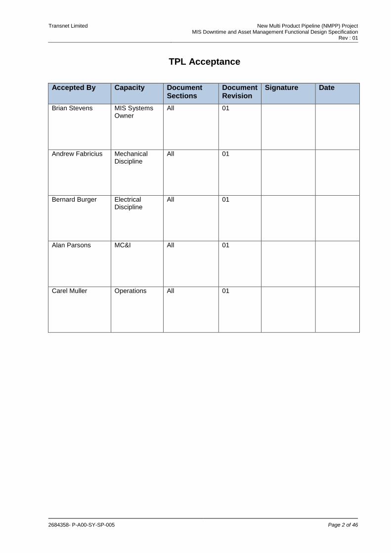
TPL Acceptance
Accepted By Capacity Document Sections
Document Revision
Signature Date
Brian Stevens MIS Systems Owner
All 01
Andrew Fabricius Mechanical Discipline
All 01
Bernard Burger Electrical Discipline
All 01
Alan Parsons MC&I All 01
Carel Muller Operations All 01

Transnet Limited New Multi Product Pipeline (NMPP) Project MIS Downtime and Asset Management Functional Design Specification
Rev : 01
2684358- P-A00-SY-SP-005 Page 3 of 46
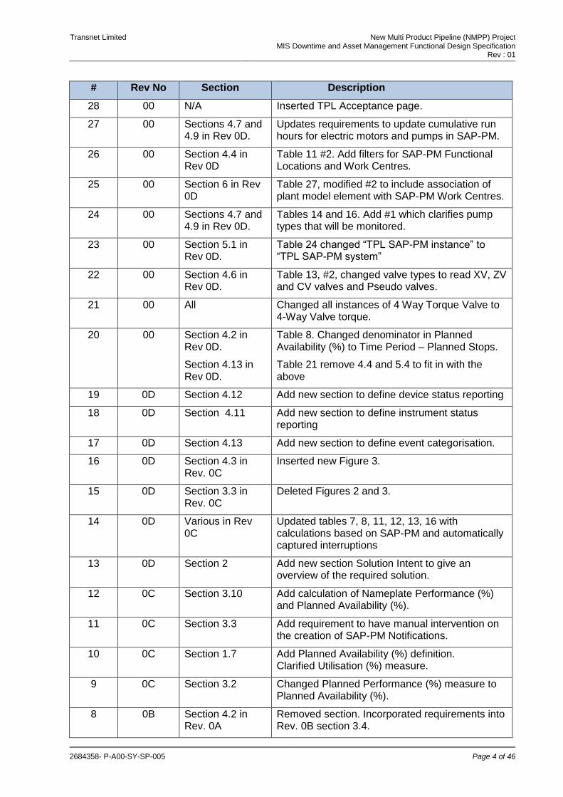
Document Revision History
# Rev No Section Description
51 01 All Updated URS reference numbering
50 01 Section 11 Added Figure 4 (information flow to achieve Downtime and Asset Monitoring requirements)
49 01 Section 4.14 Removed bullet point 6 from Table 22 (diagnostics and parameter assignment channel by channel)
48 01 Section 4.14 Removed bullet point 4 from Table 22 (Hit list for asset alarms)
47 01 Section 4.14 Removed bullet point 3 from Table 22 (status of inputs/outputs redundancy channel by channel)
46 01 Section 4.13 Removed item 7.4 (Pipeline and Station Nameplate Performance)
45 01 Section 4.13 Removed item 5.5 (Nameplate Capacity)
44 01 Section 4.13 Removed item 5.4 (Achieved effort)
43 01 Section 4.13 Removed item 4.5 (Nameplate Capacity)
42 01 Section 4.13 Removed item 4.4 (Achieved effort)
41 01 Section 4.13 Removed Nameplate Performance on item 3
40 01 Section 4.6 Removed item 5.2.2 from Table 13 (calculated valve toque)
39 01 Section 4.6 Removed item 5.2.1 from Table 13 (number of valve threshold events)
38 01 Section 4.6 Removed item 5.2
37 01 Section 4.6 Removed bullet point 4 (calculated torque value for 4-way valve)
36 01 Section 4.6 Removed item 3.2 from Table 13 (registration of event if torque calculated threshold greater than configurable threshold value)
35 01 Section 4.6 Removed item 3.1 from Table 13 (notification if torque calculated is greater than configurable threshold value)
34 01 Section 4.6 Removed item 3 from Table 13 (calculation of torque required to operate 4-way valves)
33 Section 2.4 Updated Figure 2 to show pumps for HTP
32 01 Section 2.3 Corrected spelling of identified on bullet point 6
31 01 Section 2.2 Removed item 2 from Table 5 (4-Way torque value outside min/max range)
30 01 Section 2.2 Changed logged to Calculated on bullet point 2, to be consistent with Table 5 headers
29 01 Section 1.7 Removed reference to Wonderware Historian from Table 4
Transnet Limited New Multi Product Pipeline (NMPP) Project MIS Downtime and Asset Management Functional Design Specification
Rev : 01
2684358- P-A00-SY-SP-005 Page 4 of 46
# Rev No Section Description
28 00 N/A Inserted TPL Acceptance page.
27 00 Sections 4.7 and 4.9 in Rev 0D.
Updates requirements to update cumulative run hours for electric motors and pumps in SAP-PM.
26 00 Section 4.4 in Rev 0D
Table 11 #2. Add filters for SAP-PM Functional Locations and Work Centres.
25 00 Section 6 in Rev 0D
Table 27, modified #2 to include association of plant model element with SAP-PM Work Centres.
24 00 Sections 4.7 and 4.9 in Rev 0D.
Tables 14 and 16. Add #1 which clarifies pump types that will be monitored.
23 00 Section 5.1 in Rev 0D.
Table 24 changed “TPL SAP-PM instance” to “TPL SAP-PM system”
22 00 Section 4.6 in Rev 0D.
Table 13, #2, changed valve types to read XV, ZV and CV valves and Pseudo valves.
21 00 All Changed all instances of 4 Way Torque Valve to 4-Way Valve torque.
20 00 Section 4.2 in Rev 0D.
Table 8. Changed denominator in Planned Availability (%) to Time Period – Planned Stops.
Section 4.13 in Rev 0D.
Table 21 remove 4.4 and 5.4 to fit in with the above
19 0D Section 4.12 Add new section to define device status reporting
18 0D Section 4.11 Add new section to define instrument status reporting
17 0D Section 4.13 Add new section to define event categorisation.
16 0D Section 4.3 in Rev. 0C
Inserted new Figure 3.
15 0D Section 3.3 in Rev. 0C
Deleted Figures 2 and 3.
14 0D Various in Rev 0C
Updated tables 7, 8, 11, 12, 13, 16 with calculations based on SAP-PM and automatically captured interruptions
13 0D Section 2 Add new section Solution Intent to give an overview of the required solution.
12 0C Section 3.10 Add calculation of Nameplate Performance (%) and Planned Availability (%).
11 0C Section 3.3 Add requirement to have manual intervention on the creation of SAP-PM Notifications.
10 0C Section 1.7 Add Planned Availability (%) definition. Clarified Utilisation (%) measure.
9 0C Section 3.2 Changed Planned Performance (%) measure to Planned Availability (%).
8 0B Section 4.2 in Rev. 0A
Removed section. Incorporated requirements into Rev. 0B section 3.4.
Transnet Limited New Multi Product Pipeline (NMPP) Project MIS Downtime and Asset Management Functional Design Specification
Rev : 01
2684358- P-A00-SY-SP-005 Page 5 of 46
# Rev No Section Description
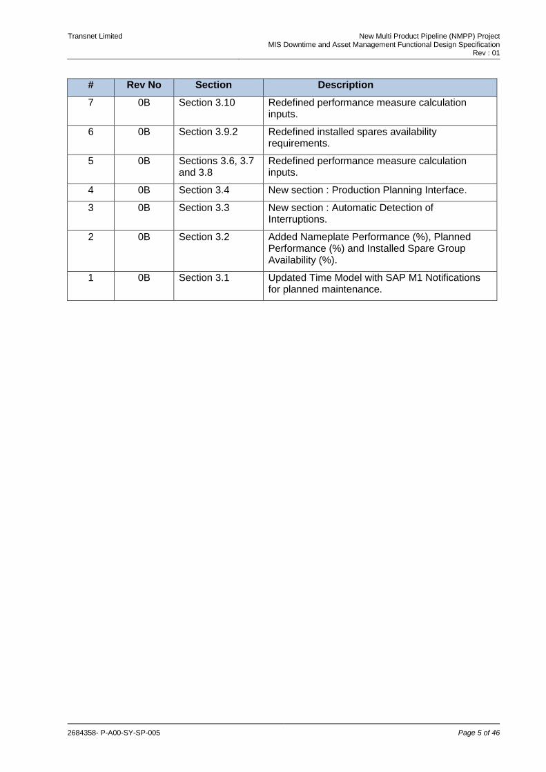
7 0B Section 3.10 Redefined performance measure calculation inputs.
6 0B Section 3.9.2 Redefined installed spares availability requirements.
5 0B Sections 3.6, 3.7 and 3.8
Redefined performance measure calculation inputs.
4 0B Section 3.4 New section : Production Planning Interface.
3 0B Section 3.3 New section : Automatic Detection of Interruptions.
2 0B Section 3.2 Added Nameplate Performance (%), Planned Performance (%) and Installed Spare Group Availability (%).
1 0B Section 3.1 Updated Time Model with SAP M1 Notifications for planned maintenance.
Transnet Limited New Multi Product Pipeline (NMPP) Project MIS Downtime and Asset Management Functional Design Specification
Rev : 01
2684358- P-A00-SY-SP-005 Page 6 of 46
Table of Contents
1. Introduction ........................................................................................................................................... 8
1.1 Document Purpose ........................................................................................................................ 8 1.2 Document Scope ........................................................................................................................... 8 1.3 Document Notation ........................................................................................................................ 8 1.4 Assumptions and Constraints ........................................................................................................ 8 1.5 References ..................................................................................................................................... 8
1.5.1 Applicable Reference ......................................................................................................... 9 1.5.2 Referenced References ..................................................................................................... 9
1.6 Abbreviations ................................................................................................................................. 9 1.7 Definitions ...................................................................................................................................... 9
2. Solution Overview and Intent ............................................................................................................ 11
2.1 Background .................................................................................................................................. 11 2.2 Events Detected and Captured .................................................................................................... 12 2.3 Performance Measures ................................................................................................................ 12 2.4 Associate Automatically Captured Events with SAP-PM Notifications ........................................ 13
3. General Requirements ........................................................................................................................ 14
3.1 Mobile Device Support ................................................................................................................. 14
4. Asset Monitoring Requirements ........................................................................................................ 14
4.1 Time Model .................................................................................................................................. 15 4.2 Performance Measures ................................................................................................................ 15 4.3 Automatic Detection and Capture Of Interruptions ...................................................................... 17 4.4 Associate Automatically Captured Events with SAP-PM Notifications ........................................ 22 4.5 Production Planning Interface ...................................................................................................... 22 4.6 Asset Monitoring : Valves ............................................................................................................ 23 4.7 Asset Monitoring : Electrical Motors ............................................................................................ 24 4.8 Asset Monitoring : Variable Speed Drives ................................................................................... 27 4.9 Asset Monitoring : Pumps ............................................................................................................ 29 4.10 Asset Monitoring : Device Groups and Installed Spares ............................................................. 32
4.10.1 Availability : Device Groups ............................................................................................. 32 4.10.2 Availability : Installed Spares ........................................................................................... 33
4.11 Asset Monitoring : Instrument Status ........................................................................................... 34 4.12 Asset Monitoring : Device Status ................................................................................................. 35 4.13 Asset Monitoring : Plant and Process Performance Monitoring .................................................. 37 4.14 Asset Monitoring : Diagnostic Dashboard .................................................................................... 39 4.15 Event Classification ...................................................................................................................... 40
5. Maintenance Management Requirements ........................................................................................ 40
5.1 Maintenance Scheduling .............................................................................................................. 40 5.2 Maintenance Reporting and Analysis .......................................................................................... 41
6. Organisational Plant/Process Modelling Requirements ................................................................. 42
7. Bentley Nevada Integration ................................................................................................................ 42
8. Ad-hoc Investigation Data/Results Management ............................................................................ 43
9. Calculation and Reporting Requirements ........................................................................................ 43
10. Disconnected Operations .................................................................................................................. 44
11. Configuration Principles .................................................................................................................... 44
12. Performance Requirements ............................................................................................................... 46
13. System Facilities and Users .............................................................................................................. 46
14. Qualification Requirements ............................................................................................................... 46
14.1 Factory Acceptance Phase .......................................................................................................... 46 14.2 Site Acceptance Phase ................................................................................................................ 46
Transnet Limited New Multi Product Pipeline (NMPP) Project MIS Downtime and Asset Management Functional Design Specification
Rev : 01
2684358- P-A00-SY-SP-005 Page 7 of 46
Index of Tables
Table 1 : Applicable References ..................................................................................................................... 9 Table 2 : References ...................................................................................................................................... 9 Table 3 : Abbreviations ................................................................................................................................... 9 Table 4 : Definitions ........................................................................................................................................ 9 Table 5 : Event Summary .............................................................................................................................12 Table 6 : Mobile Device Support ..................................................................................................................14 Table 7 : Time Model ....................................................................................................................................15 Table 8 : Performance Measures ................................................................................................................16 Table 9 : Asset Monitoring – Automatic Capture of Interruptions .................................................................19 Table 10 : Automatically Captured Interruptions ..........................................................................................20 Table 11 : Associate Automatically Captured Events with SAP-PM Notifications .......................................22 Table 12 : Asset Monitoring – Planning Interface .........................................................................................23 Table 13 : Asset Monitoring – Valves ...........................................................................................................23 Table 14 : Asset Monitoring – Electrical Motors ...........................................................................................24 Table 15 : Asset Monitoring – Variable Speed Drives ..................................................................................28 Table 16 : Asset Monitoring – Pumps...........................................................................................................29 Table 17 : Availability – Device Groups ........................................................................................................32 Table 18 : Availability – Installed Spares ......................................................................................................33 Table 19 : Asset Monitoring – Instrument Status .........................................................................................34 Table 20 : Asset Monitoring – Device Status ...............................................................................................35 Table 21 : Asset Monitoring – Plant and Process Performance Monitoring .................................................37 Table 22 : Asset Monitoring – Diagnostic Dashboard ..................................................................................39 Table 23 : Event Classification .....................................................................................................................40 Table 24 : Maintenance Scheduling Requirements ......................................................................................40 Table 25 : Maintenance Reporting and Analysis Requirements ..................................................................41 Table 26 : Plant/Process Modelling Requirements ......................................................................................42 Table 27 : Bentley Nevada Integration .........................................................................................................42 Table 28 : Ad-hoc Investigation Data/Results Management ........................................................................43 Table 29 : Reporting Requirements..............................................................................................................43 Table 30 : Disconnected Operations ............................................................................................................44 Table 31 : Configuration Principles...............................................................................................................45 Table 32 : Factory Acceptance Qualification Method Requirements ...........................................................46 Table 33 : Site Acceptance Qualification Method Requirements .................................................................46
Index of Figures
Figure 1 : Performance Calculation ..............................................................................................................13 Figure 2 : MIS Interruptions – PM Notification Association ..........................................................................13 Figure 3 : Automatic Interruption Capture ....................................................................................................18

Transnet Limited New Multi Product Pipeline (NMPP) Project MIS Downtime and Asset Management Functional Design Specification
Rev : 01
2684358- P-A00-SY-SP-005 Page 8 of 46
1. Introduction
Transnet Pipelines has a vision and strategy for its future Management Information System (MIS). This vision and strategy, together with user requirements for the MIS, is documented in the TPL Management Information System URS [4].
1.1 Document Purpose
The purpose of this document is to define the functional requirements for the Asset Monitoring and Maintenance requirements identified in the TPL Management Information System URS [4].
1.2 Document Scope
The functionality includes the following:
Asset Monitoring Requirements
Maintenance Management Requirements
Organisational Plant/Process Modelling Requirements
Bentley Nevada Integration
Ad-hoc Investigation Data and Results Management Requirements
1.3 Document Notation
An italic term in the document text indicates the use of a term, the meaning of which, applicable to this specification, is defined in Section 1.7.
In this specification, references to documents listed in Section 1.5 are denoted by [x].
Where a requirement can be traced to a requirement in a document listed in Section 1.5, it is indicated in the reference column in each requirement table.
Where applicable, a required qualification method is indicated for each requirement. The qualification methods are defined in Section 14.
1.4 Assumptions and Constraints
The following principles shall guide the definition of the required Management Information System functionality and the selection of The System components:
Proven technology/solutions should be used.
The System should be based on open industry standards.
The System should minimise the use of manual data entry.
The System shall provide a single source of the truth. While the same data may be required in different systems for performance reasons, there should be a single point of data capture and a single master source for all data.
Common solutions should be used across Pipeline, Distribution and IRP Operations.
Consistent user interface design.
Evaluate the use of existing Transnet and Transnet Pipeline solutions and application licenses before investing in new solutions and application licenses.
Minimise customisation.
1.5 References
Transnet Limited New Multi Product Pipeline (NMPP) Project MIS Downtime and Asset Management Functional Design Specification
Rev : 01
2684358- P-A00-SY-SP-005 Page 9 of 46
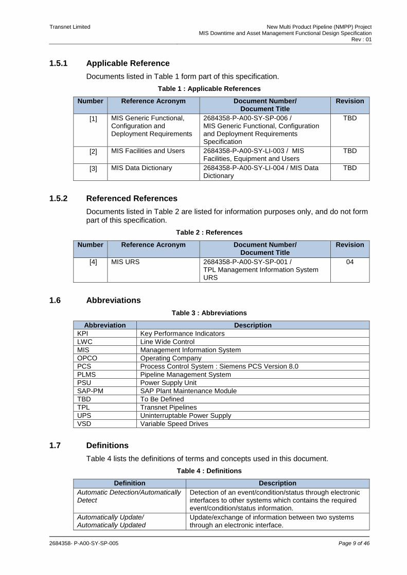
1.5.1 Applicable Reference
Documents listed in Table 1 form part of this specification.
Table 1 : Applicable References
Number Reference Acronym Document Number/ Document Title
Revision
[1] MIS Generic Functional, Configuration and Deployment Requirements
2684358-P-A00-SY-SP-006 / MIS Generic Functional, Configuration and Deployment Requirements Specification
TBD
[2] MIS Facilities and Users 2684358-P-A00-SY-LI-003 / MIS Facilities, Equipment and Users
TBD
[3] MIS Data Dictionary 2684358-P-A00-SY-LI-004 / MIS Data Dictionary
TBD
1.5.2 Referenced References
Documents listed in Table 2 are listed for information purposes only, and do not form part of this specification.
Table 2 : References
Number Reference Acronym Document Number/ Document Title
Revision
[4] MIS URS 2684358-P-A00-SY-SP-001 / TPL Management Information System URS
04
1.6 Abbreviations
Table 3 : Abbreviations
Abbreviation Description
KPI Key Performance Indicators
LWC Line Wide Control
MIS Management Information System
OPCO Operating Company
PCS Process Control System : Siemens PCS Version 8.0
PLMS Pipeline Management System
PSU Power Supply Unit
SAP-PM SAP Plant Maintenance Module
TBD To Be Defined
TPL Transnet Pipelines
UPS Uninterruptable Power Supply
VSD Variable Speed Drives
1.7 Definitions
Table 4 lists the definitions of terms and concepts used in this document.
Table 4 : Definitions
Definition Description
Automatic Detection/Automatically Detect
Detection of an event/condition/status through electronic interfaces to other systems which contains the required event/condition/status information.
Automatically Update/ Automatically Updated
Update/exchange of information between two systems through an electronic interface.
Transnet Limited New Multi Product Pipeline (NMPP) Project MIS Downtime and Asset Management Functional Design Specification
Rev : 01
2684358- P-A00-SY-SP-005 Page 10 of 46
Definition Description
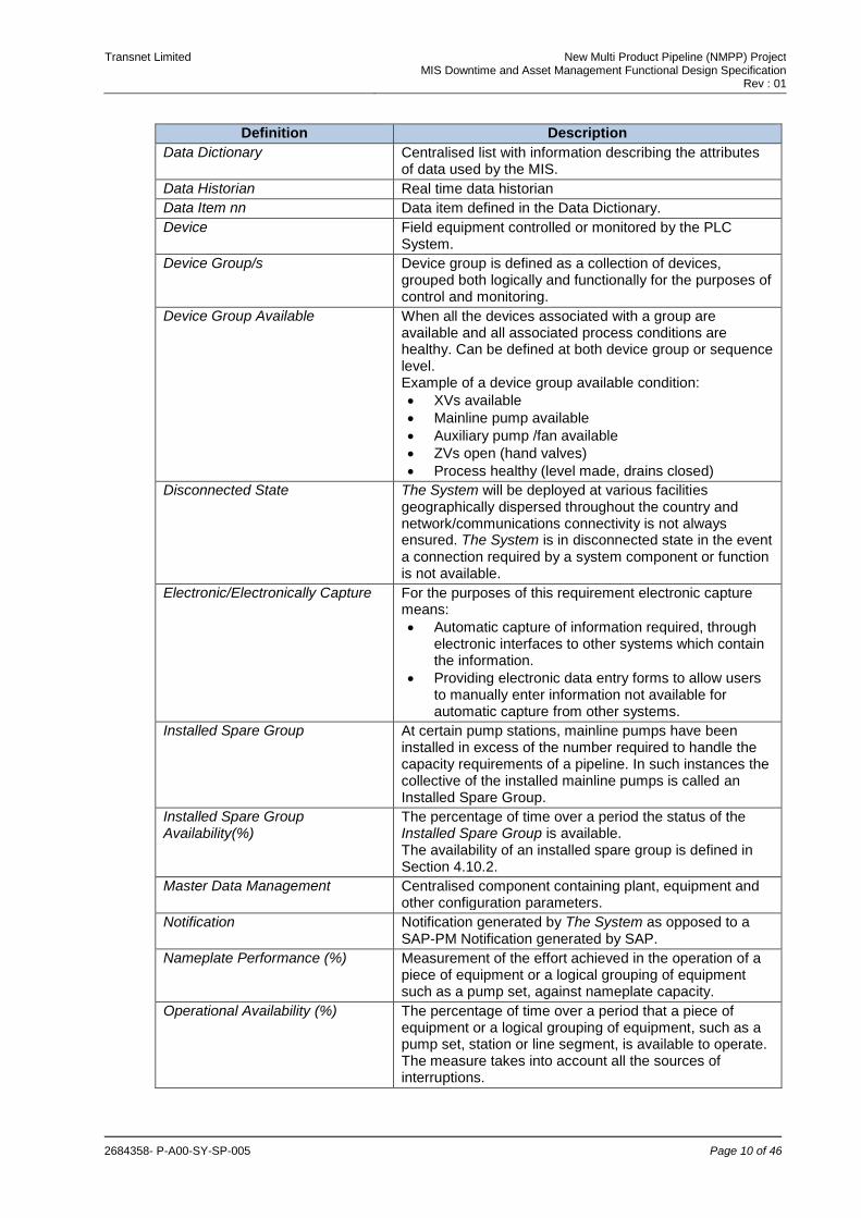
Data Dictionary Centralised list with information describing the attributes of data used by the MIS.
Data Historian Real time data historian
Data Item nn Data item defined in the Data Dictionary.
Device Field equipment controlled or monitored by the PLC System.
Device Group/s Device group is defined as a collection of devices, grouped both logically and functionally for the purposes of control and monitoring.
Device Group Available When all the devices associated with a group are available and all associated process conditions are healthy. Can be defined at both device group or sequence level. Example of a device group available condition:
XVs available
Mainline pump available
Auxiliary pump /fan available
ZVs open (hand valves)
Process healthy (level made, drains closed)
Disconnected State The System will be deployed at various facilities geographically dispersed throughout the country and network/communications connectivity is not always ensured. The System is in disconnected state in the event a connection required by a system component or function is not available.
Electronic/Electronically Capture For the purposes of this requirement electronic capture means:
Automatic capture of information required, through electronic interfaces to other systems which contain the information.
Providing electronic data entry forms to allow users to manually enter information not available for automatic capture from other systems.
Installed Spare Group At certain pump stations, mainline pumps have been installed in excess of the number required to handle the capacity requirements of a pipeline. In such instances the collective of the installed mainline pumps is called an Installed Spare Group.
Installed Spare Group Availability(%)
The percentage of time over a period the status of the Installed Spare Group is available. The availability of an installed spare group is defined in Section 4.10.2.
Master Data Management Centralised component containing plant, equipment and other configuration parameters.
Notification Notification generated by The System as opposed to a SAP-PM Notification generated by SAP.
Nameplate Performance (%)
Measurement of the effort achieved in the operation of a piece of equipment or a logical grouping of equipment such as a pump set, against nameplate capacity.
Operational Availability (%) The percentage of time over a period that a piece of equipment or a logical grouping of equipment, such as a pump set, station or line segment, is available to operate. The measure takes into account all the sources of interruptions.
Transnet Limited New Multi Product Pipeline (NMPP) Project MIS Downtime and Asset Management Functional Design Specification
Rev : 01
2684358- P-A00-SY-SP-005 Page 11 of 46
Definition Description
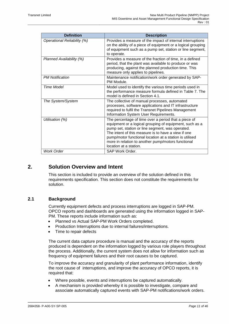
Operational Reliability (%)
Provides a measure of the impact of internal interruptions on the ability of a piece of equipment or a logical grouping of equipment such as a pump set, station or line segment, to operate.
Planned Availability (%)
Provides a measure of the fraction of time, in a defined period, that the plant was available to produce or was producing, against the planned production time. This measure only applies to pipelines.
PM Notification Maintenance notification/work order generated by SAP-PM Module.
Time Model Model used to identify the various time periods used in the performance measure formula defined in Table 7. The model is defined in Section 4.1.
The System/System The collective of manual processes, automated processes, software applications and IT infrastructure required to fulfil the Transnet Pipelines Management Information System User Requirements.
Utilisation (%)
The percentage of time over a period that a piece of equipment or a logical grouping of equipment, such as a pump set, station or line segment, was operated. The intent of this measure is to have a view if one pump/motor functional location at a station is utilised more in relation to another pump/motors functional location at a station.
Work Order SAP Work Order.
2. Solution Overview and Intent
This section is included to provide an overview of the solution defined in this requirements specification. This section does not constitute the requirements for solution.
2.1 Background
Currently equipment defects and process interruptions are logged in SAP-PM. OPCO reports and dashboards are generated using the information logged in SAP-PM. These reports include information such as:
Planned vs Actual SAP-PM Work Orders completed.
Production Interruptions due to internal failures/interruptions.
Time to repair defects The current data capture procedure is manual and the accuracy of the reports produced is dependent on the information logged by various role players throughout the process. Additionally, the current system does not allow for information such as frequency of equipment failures and their root causes to be captured.
To improve the accuracy and granularity of plant performance information, identify the root cause of interruptions, and improve the accuracy of OPCO reports, it is required that:
Where possible, events and interruptions be captured automatically.
A mechanism is provided whereby it is possible to investigate, compare and associate automatically captured events with SAP-PM notifications/work orders.

Transnet Limited New Multi Product Pipeline (NMPP) Project MIS Downtime and Asset Management Functional Design Specification
Rev : 01
2684358- P-A00-SY-SP-005 Page 12 of 46
In addition to the current performance measures reported in the OPCO reports, a set of performance measures is required which will give an indication of equipment and plant availability and reliability.
2.2 Events Detected and Captured
Table 5 provides a summary of event types identified in this specification. The table identifies the following for each event type:
Event Logged: Identifies whether the event will be logged by The System.
Event Duration Calculated: Identifies whether the event duration will be calculated by The System.
MIS Notification: Identifies whether a Notification will be generated by The System on the event.
PM Notification: Identifies whether a PM Notification will be generated by The System on the event.
Table 5 : Event Summary
# Event Type Event Logged
Event Duration Calculated
MIS Notification PM Notification
1 Interruptions as per Table 10.
Yes Yes Yes Manual intervention or automatic depending on configuration
2 Motor Stop/Start Events.
Yes No No No
3 Valve Open/Close Events.
Yes No No No
4 Performance Measure outside min/max range.
Yes Yes Yes No
5 Device Group status change from available to not available.
Yes No Yes No
6 Installed Spare Group status change from available to not available.
Yes No Yes No
7 Bentley Nevada evaluations outside min/max range.
Yes No Yes No
2.3 Performance Measures
The following performance measures, defined in Section 4.2, need to be calculated:
Operational Availability (%)
Operational Reliability (%)
Utilisation (%)
Nameplate Performance (%)
Planned Performance (%)
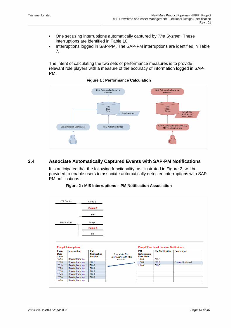
Two sets of the above performance measures need to be calculated as illustrated in Figure 1:
Transnet Limited New Multi Product Pipeline (NMPP) Project MIS Downtime and Asset Management Functional Design Specification
Rev : 01
2684358- P-A00-SY-SP-005 Page 13 of 46
One set using interruptions automatically captured by The System. These interruptions are identified in Table 10.
Interruptions logged in SAP-PM. The SAP-PM interruptions are identified in Table 7.
The intent of calculating the two sets of performance measures is to provide relevant role players with a measure of the accuracy of information logged in SAP-PM.
Figure 1 : Performance Calculation
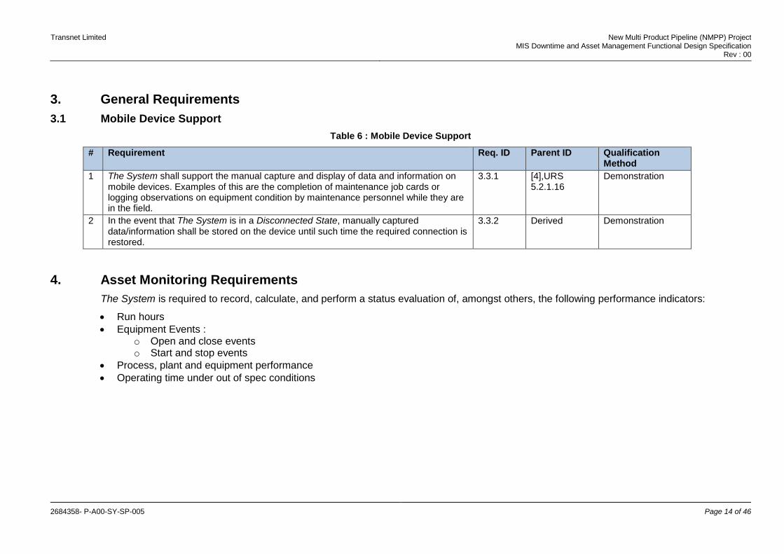
2.4 Associate Automatically Captured Events with SAP-PM Notifications
It is anticipated that the following functionality, as illustrated in Figure 2, will be provided to enable users to associate automatically detected interruptions with SAP- PM notifications.
Figure 2 : MIS Interruptions – PM Notification Association
TNI Station Pump 1
Pump 2
etc
HTP Station Pump 1
Pump 2
etc
Transnet Limited New Multi Product Pipeline (NMPP) Project MIS Downtime and Asset Management Functional Design Specification
Rev : 00
2684358- P-A00-SY-SP-005 Page 14 of 46
3. General Requirements
3.1 Mobile Device Support
Table 6 : Mobile Device Support
# Requirement Req. ID Parent ID Qualification Method
1 The System shall support the manual capture and display of data and information on mobile devices. Examples of this are the completion of maintenance job cards or logging observations on equipment condition by maintenance personnel while they are in the field.
3.3.1 [4],URS 5.2.1.16
Demonstration
2 In the event that The System is in a Disconnected State, manually captured data/information shall be stored on the device until such time the required connection is restored.
3.3.2 Derived Demonstration
4. Asset Monitoring Requirements
The System is required to record, calculate, and perform a status evaluation of, amongst others, the following performance indicators:
Run hours
Equipment Events : o Open and close events o Start and stop events
Process, plant and equipment performance
Operating time under out of spec conditions
Transnet Limited New Multi Product Pipeline (NMPP) Project MIS Downtime and Asset Management Functional Design Specification
Rev : 00
2684358- P-A00-SY-SP-005 Page 15 of 46
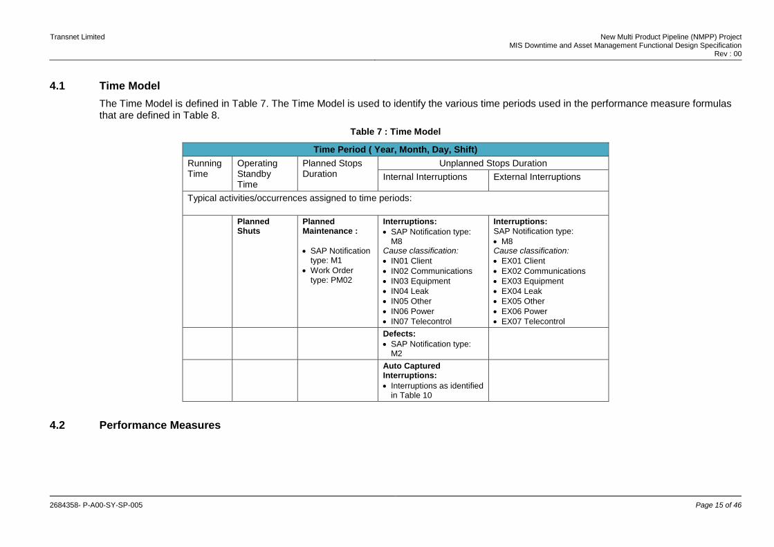
4.1 Time Model
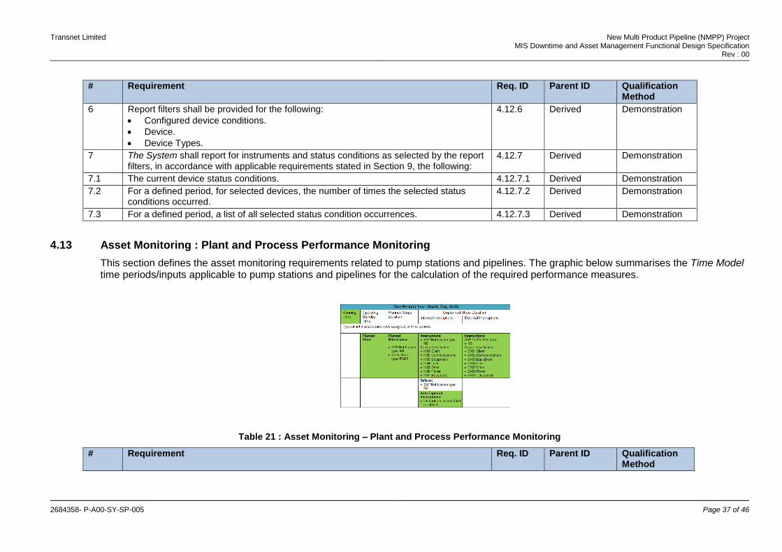
The Time Model is defined in Table 7. The Time Model is used to identify the various time periods used in the performance measure formulas that are defined in Table 8.
Table 7 : Time Model
Time Period ( Year, Month, Day, Shift)
Running Time
Operating Standby Time
Planned Stops Duration
Unplanned Stops Duration
Internal Interruptions External Interruptions
Typical activities/occurrences assigned to time periods:
Planned Shuts
Planned Maintenance :
SAP Notification type: M1
Work Order type: PM02
Interruptions:
SAP Notification type: M8
Cause classification:
IN01 Client
IN02 Communications
IN03 Equipment
IN04 Leak
IN05 Other
IN06 Power
IN07 Telecontrol
Interruptions:
SAP Notification type:
M8 Cause classification:
EX01 Client
EX02 Communications
EX03 Equipment
EX04 Leak
EX05 Other
EX06 Power
EX07 Telecontrol
Defects:
SAP Notification type: M2
Auto Captured Interruptions:
Interruptions as identified in Table 10
4.2 Performance Measures
Transnet Limited New Multi Product Pipeline (NMPP) Project MIS Downtime and Asset Management Functional Design Specification
Rev : 00
2684358- P-A00-SY-SP-005 Page 16 of 46
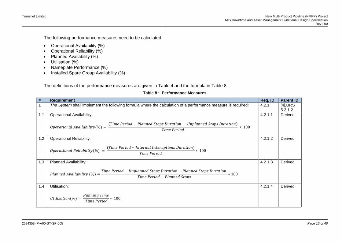
The following performance measures need to be calculated:
Operational Availability (%)
Operational Reliability (%)
Planned Availability (%)
Utilisation (%)
Nameplate Performance (%)
Installed Spare Group Availability (%)
The definitions of the performance measures are given in Table 4 and the formula in Table 8.
Table 8 : Performance Measures
# Requirement Req. ID Parent ID
1 The System shall implement the following formula where the calculation of a performance measure is required: 4.2.1 [4],URS 5.2.1.2
1.1 Operational Availability:
𝑂𝑝𝑒𝑟𝑎𝑡𝑖𝑜𝑛𝑎𝑙 𝐴𝑣𝑎𝑖𝑙𝑎𝑏𝑖𝑙𝑖𝑡𝑦(%) = (𝑇𝑖𝑚𝑒 𝑃𝑒𝑟𝑖𝑜𝑑 − 𝑃𝑙𝑎𝑛𝑛𝑒𝑑 𝑆𝑡𝑜𝑝𝑠 𝐷𝑢𝑟𝑎𝑡𝑖𝑜𝑛 − 𝑈𝑛𝑝𝑙𝑎𝑛𝑛𝑒𝑑 𝑆𝑡𝑜𝑝𝑠 𝐷𝑢𝑟𝑎𝑡𝑖𝑜𝑛)
𝑇𝑖𝑚𝑒 𝑃𝑒𝑟𝑖𝑜𝑑 ∗ 100
4.2.1.1 Derived
1.2 Operational Reliability:
𝑂𝑝𝑒𝑟𝑎𝑡𝑖𝑜𝑛𝑎𝑙 𝑅𝑒𝑙𝑖𝑎𝑏𝑖𝑙𝑖𝑡𝑦(%) = (𝑇𝑖𝑚𝑒 𝑃𝑒𝑟𝑖𝑜𝑑 – 𝐼𝑛𝑡𝑒𝑟𝑛𝑎𝑙 𝐼𝑛𝑡𝑒𝑟𝑢𝑝𝑡𝑖𝑜𝑛𝑠 𝐷𝑢𝑟𝑎𝑡𝑖𝑜𝑛)
𝑇𝑖𝑚𝑒 𝑃𝑒𝑟𝑖𝑜𝑑∗ 100
4.2.1.2 Derived
1.3 Planned Availability:
𝑃𝑙𝑎𝑛𝑛𝑒𝑑 𝐴𝑣𝑎𝑖𝑙𝑎𝑏𝑖𝑙𝑖𝑡𝑦 (%) =𝑇𝑖𝑚𝑒 𝑃𝑒𝑟𝑖𝑜𝑑 − 𝑈𝑛𝑝𝑙𝑎𝑛𝑛𝑒𝑑 𝑆𝑡𝑜𝑝𝑠 𝐷𝑢𝑟𝑎𝑡𝑖𝑜𝑛 − 𝑃𝑙𝑎𝑛𝑛𝑒𝑑 𝑆𝑡𝑜𝑝𝑠 𝐷𝑢𝑟𝑎𝑡𝑖𝑜𝑛
𝑇𝑖𝑚𝑒 𝑃𝑒𝑟𝑖𝑜𝑑 − 𝑃𝑙𝑎𝑛𝑛𝑒𝑑 𝑆𝑡𝑜𝑝𝑠∗ 100
4.2.1.3 Derived
1.4 Utilisation:
𝑈𝑡𝑖𝑙𝑖𝑠𝑎𝑡𝑖𝑜𝑛(%) = 𝑅𝑢𝑛𝑛𝑖𝑛𝑔 𝑇𝑖𝑚𝑒
𝑇𝑖𝑚𝑒 𝑃𝑒𝑟𝑖𝑜𝑑∗ 100
4.2.1.4 Derived
Transnet Limited New Multi Product Pipeline (NMPP) Project MIS Downtime and Asset Management Functional Design Specification
Rev : 00
2684358- P-A00-SY-SP-005 Page 17 of 46
# Requirement Req. ID Parent ID
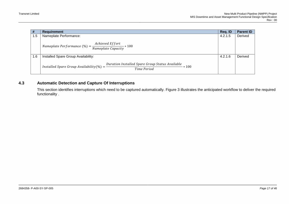
1.5 Nameplate Performance:
𝑁𝑎𝑚𝑒𝑝𝑙𝑎𝑡𝑒 𝑃𝑒𝑟𝑓𝑜𝑟𝑚𝑎𝑛𝑐𝑒 (%) =𝐴𝑐ℎ𝑖𝑒𝑣𝑒𝑑 𝐸𝑓𝑓𝑜𝑟𝑡
𝑁𝑎𝑚𝑒𝑝𝑙𝑎𝑡𝑒 𝐶𝑎𝑝𝑎𝑐𝑖𝑡𝑦∗ 100
4.2.1.5 Derived
1.6 Installed Spare Group Availability:
𝐼𝑛𝑠𝑡𝑎𝑙𝑙𝑒𝑑 𝑆𝑝𝑎𝑟𝑒 𝐺𝑟𝑜𝑢𝑝 𝐴𝑣𝑎𝑖𝑙𝑎𝑏𝑖𝑙𝑖𝑡𝑦(%) =𝐷𝑢𝑟𝑎𝑡𝑖𝑜𝑛 𝐼𝑛𝑠𝑡𝑎𝑙𝑙𝑒𝑑 𝑆𝑝𝑎𝑟𝑒 𝐺𝑟𝑜𝑢𝑝 𝑆𝑡𝑎𝑡𝑢𝑠 𝐴𝑣𝑎𝑖𝑙𝑎𝑏𝑙𝑒
𝑇𝑖𝑚𝑒 𝑃𝑒𝑟𝑖𝑜𝑑∗ 100
4.2.1.6 Derived
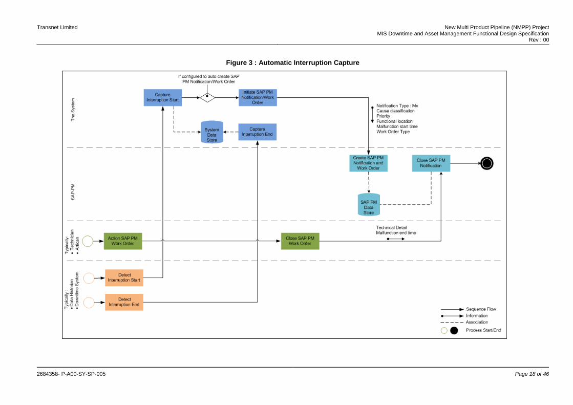
4.3 Automatic Detection and Capture Of Interruptions
This section identifies interruptions which need to be captured automatically. Figure 3 illustrates the anticipated workflow to deliver the required functionality .
Transnet Limited New Multi Product Pipeline (NMPP) Project MIS Downtime and Asset Management Functional Design Specification
Rev : 00
2684358- P-A00-SY-SP-005 Page 18 of 46
Figure 3 : Automatic Interruption Capture
Transnet Limited New Multi Product Pipeline (NMPP) Project MIS Downtime and Asset Management Functional Design Specification
Rev : 00
2684358- P-A00-SY-SP-005 Page 19 of 46
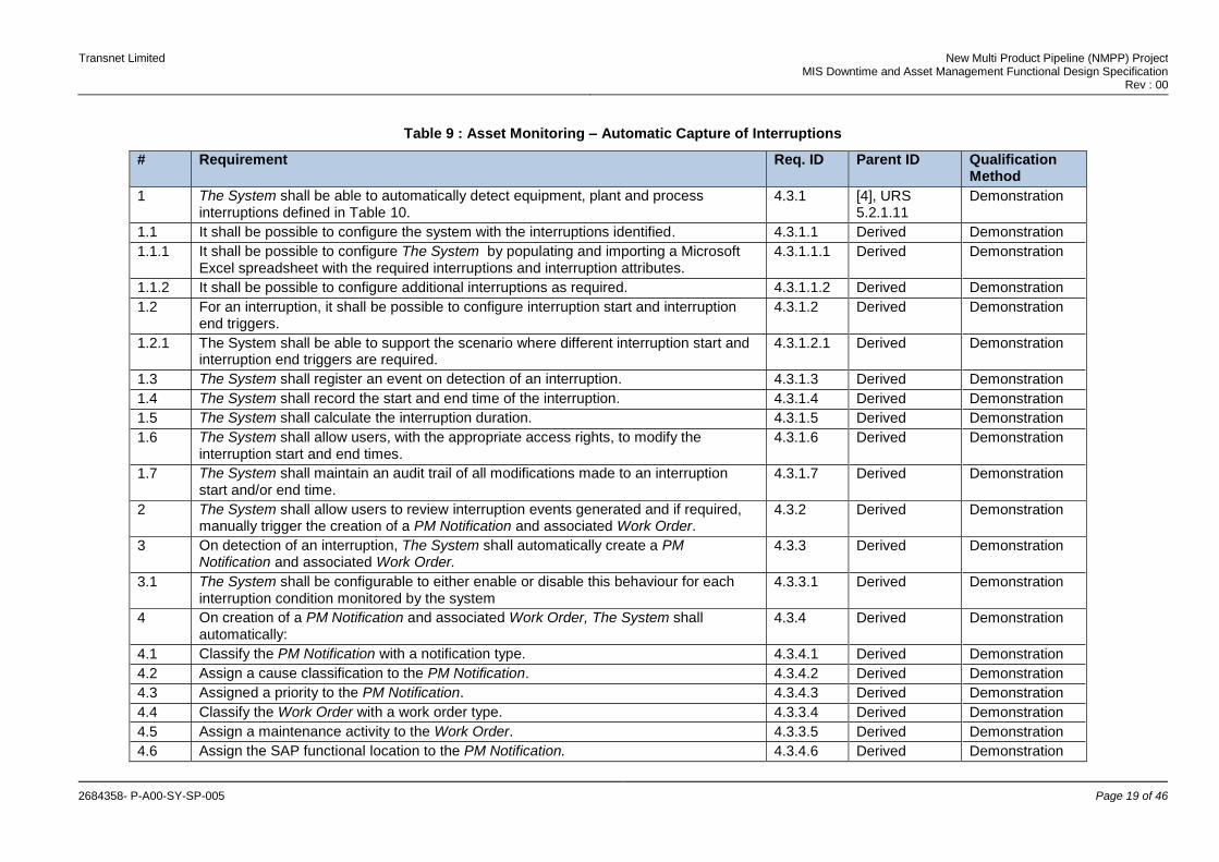
Table 9 : Asset Monitoring – Automatic Capture of Interruptions
# Requirement Req. ID Parent ID Qualification Method
1 The System shall be able to automatically detect equipment, plant and process interruptions defined in Table 10.
4.3.1 [4], URS 5.2.1.11
Demonstration
1.1 It shall be possible to configure the system with the interruptions identified. 4.3.1.1 Derived Demonstration
1.1.1 It shall be possible to configure The System by populating and importing a Microsoft Excel spreadsheet with the required interruptions and interruption attributes.
4.3.1.1.1 Derived Demonstration
1.1.2 It shall be possible to configure additional interruptions as required. 4.3.1.1.2 Derived Demonstration
1.2 For an interruption, it shall be possible to configure interruption start and interruption end triggers.
4.3.1.2 Derived Demonstration
1.2.1 The System shall be able to support the scenario where different interruption start and interruption end triggers are required.
4.3.1.2.1 Derived Demonstration
1.3 The System shall register an event on detection of an interruption. 4.3.1.3 Derived Demonstration
1.4 The System shall record the start and end time of the interruption. 4.3.1.4 Derived Demonstration
1.5 The System shall calculate the interruption duration. 4.3.1.5 Derived Demonstration
1.6 The System shall allow users, with the appropriate access rights, to modify the interruption start and end times.
4.3.1.6 Derived Demonstration
1.7 The System shall maintain an audit trail of all modifications made to an interruption start and/or end time.
4.3.1.7 Derived Demonstration
2 The System shall allow users to review interruption events generated and if required, manually trigger the creation of a PM Notification and associated Work Order.
4.3.2 Derived Demonstration
3 On detection of an interruption, The System shall automatically create a PM Notification and associated Work Order.
4.3.3 Derived Demonstration
3.1 The System shall be configurable to either enable or disable this behaviour for each interruption condition monitored by the system
4.3.3.1 Derived Demonstration
4 On creation of a PM Notification and associated Work Order, The System shall automatically:
4.3.4 Derived Demonstration
4.1 Classify the PM Notification with a notification type. 4.3.4.1 Derived Demonstration
4.2 Assign a cause classification to the PM Notification. 4.3.4.2 Derived Demonstration
4.3 Assigned a priority to the PM Notification. 4.3.4.3 Derived Demonstration
4.4 Classify the Work Order with a work order type. 4.3.3.4 Derived Demonstration
4.5 Assign a maintenance activity to the Work Order. 4.3.3.5 Derived Demonstration
4.6 Assign the SAP functional location to the PM Notification. 4.3.4.6 Derived Demonstration

Transnet Limited New Multi Product Pipeline (NMPP) Project MIS Downtime and Asset Management Functional Design Specification
Rev : 00
2684358- P-A00-SY-SP-005 Page 20 of 46
# Requirement Req. ID Parent ID Qualification Method
5 In the case where the user triggers the creation of the PM Notification and associated Work Order, The System shall pre-populate the above information for the user and provide the user with the ability to modify the information as required before the PM Notification and associated Work Order is created.
4.3.5 Derived Demonstration
6 It shall be possible to configure the following associated with an interruption:
Notification type
Notification priority
Cause classification
Work order type
Maintenance activity
SAP functional location
4.3.6 Derived Demonstration
6.1 The System shall integrate with SAP-PM to present to the user, during the configuration process, valid lists of :
Notification types and associated priorities and/or work order types.
Maintenance activities associated with work order types.
4.3.6.1 Derived Demonstration
6.2 The System shall be able to accommodate instances were a notification classification does not have an associated priority and/or Work Order.
4.3.6.2 Derived Demonstration
7 The System shall provide the functionality to manually create an interruption record in the event that an automatic interruption record is not created by The System.
4.3.7 Derived Demonstration
Table 10 provides a list of interruptions for the equipment types, stations and pipelines indicated. A ‘Yes’ in a column means that the interruption will be attributed to the entity identified in the column. The interruption duration will be used to calculate the entity performance measures. An ‘I’ or ‘E’ indicates if the interruption is an internal or external interruption.
Table 10 : Automatically Captured Interruptions
# Unplanned Interruptions Mainline Pump
I/E Electrical Motor
I/E VSD I/E Pump Station
I/E Pipeline I/E
Interlocks 1 Station No Valid Flow Path Trip. - - - - - - Yes I - - 2 Line Over-Pressure SIL System Trip. - - - - - - Yes I - - 3 Lube Oil System Not Healthy. Yes I - - - - - - -

Transnet Limited New Multi Product Pipeline (NMPP) Project MIS Downtime and Asset Management Functional Design Specification
Rev : 00
2684358- P-A00-SY-SP-005 Page 21 of 46
# Unplanned Interruptions Mainline Pump
I/E Electrical Motor
I/E VSD I/E Pump Station
I/E Pipeline I/E
Mechanical Trips 4 Pump Seal Leak NDE. Yes I - - - - - - - - 5 Pump Seal Leak DE. Yes I - - - - - - - - 6 Pump Bearing Temperature High Trip. Yes I - - - - - - - - 7 Pump Vibration High Trip. Yes I - - - - - - - - 8 Pump Radial Bearing Vibration High. Yes I - - - - - - - - 9 Pump Thrust Bearing Axial Displacement Alarm. Yes I - - - - - - - - 10 Pump Thrust Bearing Axial Displacement Alarm. Yes I - - - - - - - - 11 Motor bearing Temperature High Trip. - - Yes I - - - - - - 12 Motor Vibration High Trip. - - Yes I - - - - - - Electrical Trip 13 Emergency Stop. - - - - - - Yes I - - 14 VSD Master Trip. - - - - Yes I - - - - 15 Motor Winding Temperature High Trip. - - Yes I - - - - - - 16 Motor Winding Temperature Wire Break. - - Yes I - - - - - - Process Trip 17 Pump Casing Temp High. - - - - - - Yes I - - 18 Pump Suction Pressure Low Trip. - - - - - - Yes I - - 19 Pump Discharge Pressure High Trip. - - - - - - Yes I - - 20 No Product Flow. - - - - - - Yes I - - 21 VSD Chiller Fault. - - - - Yes I - - - - Device Faults 22 VSD Communication Failure. - - Yes I - - - - - - 23 Control Error. - - Yes I - - - - - - Station Faults 24 Station Fire Detected. - - - - - - Yes I - - 25 Station Receiver fault. - - - - - - Yes I - - 26 Station Emergency Stop. - - - - - - Yes I - - 27 Utility Power fail - - - - - - Yes E - - Line Faults 28 Block Valves Not Opened. - - - - - - - - Yes I
Transnet Limited New Multi Product Pipeline (NMPP) Project MIS Downtime and Asset Management Functional Design Specification
Rev : 00
2684358- P-A00-SY-SP-005 Page 22 of 46
4.4 Associate Automatically Captured Events with SAP-PM Notifications
This section identifies requirements to associate SAP-PM Notifications with events captured. The intent of the requirements stated in this section is detailed in Section 2.4.
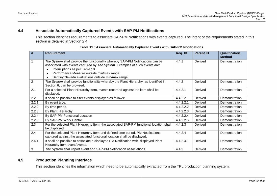
Table 11 : Associate Automatically Captured Events with SAP-PM Notifications
# Requirement Req. ID Parent ID Qualification Method
1 The System shall provide the functionality whereby SAP-PM Notifications can be associated with events captured by The System. Examples of such events are:
Interruptions as per Table 10.
Performance Measure outside min/max range.
Bentley Nevada evaluations outside min/max range.
4.4.1 Derived Demonstration
2 The System shall provide functionality whereby the Plant Hierarchy, as identified in Section 6, can be browsed.
4.4.2 Derived Demonstration
2.1 For a selected Plant Hierarchy Item, events recorded against the item shall be displayed.
4.4.2.1 Derived Demonstration
2.2 It shall be possible to filter events displayed as follows: 4.4.2.2 Derived Demonstration
2.2.1 By event type. 4.4.2.2.1 Derived Demonstration
2.2.2 By time period. 4.4.2.2.2 Derived Demonstration
2.2.3 By Plant Hierarchy 4.4.2.2.3 Derived Demonstration
2.2.4 By SAP-PM Functional Location 4.4.2.2.4 Derived Demonstration
2.2.5 By SAP-PM Work Centre 4.4.2.2.5 Derived Demonstration
2.3 For the selected Plant Hierarchy Item, the associated SAP-PM functional location shall be displayed.
4.4.2.3 Derived Demonstration
2.4 For the selected Plant Hierarchy Item and defined time period, PM Notifications captured against the associated functional location shall be displayed.
4.4.2.4 Derived Demonstration
2.4.1 It shall be possible to associate a displayed PM Notification with displayed Plant Hierarchy Item event/events.
4.4.2.4.1 Derived Demonstration
3 The System shall report event and SAP-PM Notification associations. 4.4.3 Derived Demonstration
4.5 Production Planning Interface
This section identifies the information which need to be automatically extracted from the TPL production planning system.
Transnet Limited New Multi Product Pipeline (NMPP) Project MIS Downtime and Asset Management Functional Design Specification
Rev : 00
2684358- P-A00-SY-SP-005 Page 23 of 46
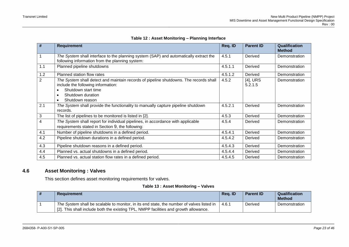
Table 12 : Asset Monitoring – Planning Interface
# Requirement Req. ID Parent ID Qualification Method
1 The System shall interface to the planning system (SAP) and automatically extract the following information from the planning system:
4.5.1 Derived Demonstration
1.1 Planned pipeline shutdowns 4.5.1.1 Derived Demonstration
1.2 Planned station flow rates 4.5.1.2 Derived Demonstration
2 The System shall detect and maintain records of pipeline shutdowns. The records shall include the following information:
Shutdown start time
Shutdown duration
Shutdown reason
4.5.2 [4], URS 5.2.1.5
Demonstration
2.1 The System shall provide the functionality to manually capture pipeline shutdown records.
4.5.2.1 Derived Demonstration
3 The list of pipelines to be monitored is listed in [2]. 4.5.3 Derived Demonstration
4 The System shall report for individual pipelines, in accordance with applicable
requirements stated in Section 9, the following:
4.5.4 Derived Demonstration
4.1 Number of pipeline shutdowns in a defined period. 4.5.4.1 Derived Demonstration
4.2 Pipeline shutdown durations in a defined period. 4.5.4.2 Derived Demonstration
4.3 Pipeline shutdown reasons in a defined period. 4.5.4.3 Derived Demonstration
4.4 Planned vs. actual shutdowns in a defined period. 4.5.4.4 Derived Demonstration
4.5 Planned vs. actual station flow rates in a defined period. 4.5.4.5 Derived Demonstration
4.6 Asset Monitoring : Valves
This section defines asset monitoring requirements for valves.
Table 13 : Asset Monitoring – Valves
# Requirement Req. ID Parent ID Qualification Method
1 The System shall be scalable to monitor, in its end state, the number of valves listed in
[2]. This shall include both the existing TPL, NMPP facilities and growth allowance.
4.6.1 Derived Demonstration

Transnet Limited New Multi Product Pipeline (NMPP) Project MIS Downtime and Asset Management Functional Design Specification
Rev : 00
2684358- P-A00-SY-SP-005 Page 24 of 46
# Requirement Req. ID Parent ID Qualification Method
2 The System shall Automatically Detect and Electronically Capture open and close events for the following types of valves:
XV, ZV and CV valves.
Pseudo valves. (Pseudo valves are created in the PCS to record the status of manual valves for which no control or position feedback signal exist).
4.6.2 [4], URS, 5.2.1.1
Demonstration
3 The following information shall be captured for each open and close event of all types of valves:
Valve Identifier
Event date and time
Event type : Open or Close
4.6.4 Derived Demonstration
4 The System shall report, in accordance with applicable requirements stated in Section 9, the following:
4.6.5 Derived Demonstration
4.1 For individual valves, the number of valve opening and closing events 4.6.5.1 Derived Demonstration
4.7 Asset Monitoring : Electrical Motors
This section defines electric motor asset monitoring requirements. The graphic below summarises the Time Model time periods/inputs applicable to electrical motors for the calculation of the required performance measures.
Table 14 : Asset Monitoring – Electrical Motors
# Requirement Req. ID Parent ID Qualification Method
Transnet Limited New Multi Product Pipeline (NMPP) Project MIS Downtime and Asset Management Functional Design Specification
Rev : 00
2684358- P-A00-SY-SP-005 Page 25 of 46
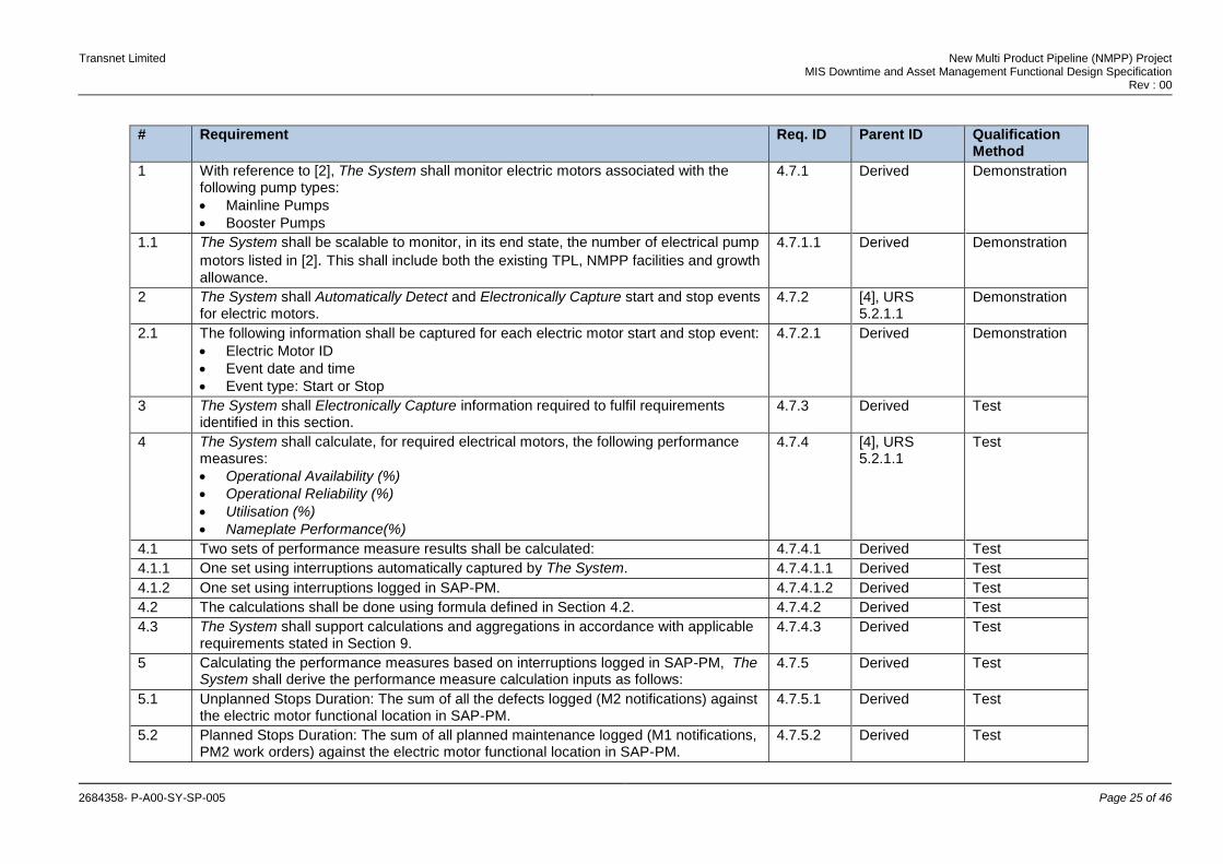
# Requirement Req. ID Parent ID Qualification Method
1 With reference to [2], The System shall monitor electric motors associated with the following pump types:
Mainline Pumps
Booster Pumps
4.7.1 Derived Demonstration
1.1 The System shall be scalable to monitor, in its end state, the number of electrical pump
motors listed in [2]. This shall include both the existing TPL, NMPP facilities and growth
allowance.
4.7.1.1 Derived Demonstration
2 The System shall Automatically Detect and Electronically Capture start and stop events for electric motors.
4.7.2 [4], URS 5.2.1.1
Demonstration
2.1 The following information shall be captured for each electric motor start and stop event:
Electric Motor ID
Event date and time
Event type: Start or Stop
4.7.2.1 Derived Demonstration
3 The System shall Electronically Capture information required to fulfil requirements identified in this section.
4.7.3 Derived Test
4 The System shall calculate, for required electrical motors, the following performance measures:
Operational Availability (%)
Operational Reliability (%)
Utilisation (%)
Nameplate Performance(%)
4.7.4 [4], URS 5.2.1.1
Test
4.1 Two sets of performance measure results shall be calculated: 4.7.4.1 Derived Test
4.1.1 One set using interruptions automatically captured by The System. 4.7.4.1.1 Derived Test
4.1.2 One set using interruptions logged in SAP-PM. 4.7.4.1.2 Derived Test
4.2 The calculations shall be done using formula defined in Section 4.2. 4.7.4.2 Derived Test
4.3 The System shall support calculations and aggregations in accordance with applicable requirements stated in Section 9.
4.7.4.3 Derived Test
5 Calculating the performance measures based on interruptions logged in SAP-PM, The System shall derive the performance measure calculation inputs as follows:
4.7.5 Derived Test
5.1 Unplanned Stops Duration: The sum of all the defects logged (M2 notifications) against the electric motor functional location in SAP-PM.
4.7.5.1 Derived Test
5.2 Planned Stops Duration: The sum of all planned maintenance logged (M1 notifications, PM2 work orders) against the electric motor functional location in SAP-PM.
4.7.5.2 Derived Test
Transnet Limited New Multi Product Pipeline (NMPP) Project MIS Downtime and Asset Management Functional Design Specification
Rev : 00
2684358- P-A00-SY-SP-005 Page 26 of 46
# Requirement Req. ID Parent ID Qualification Method
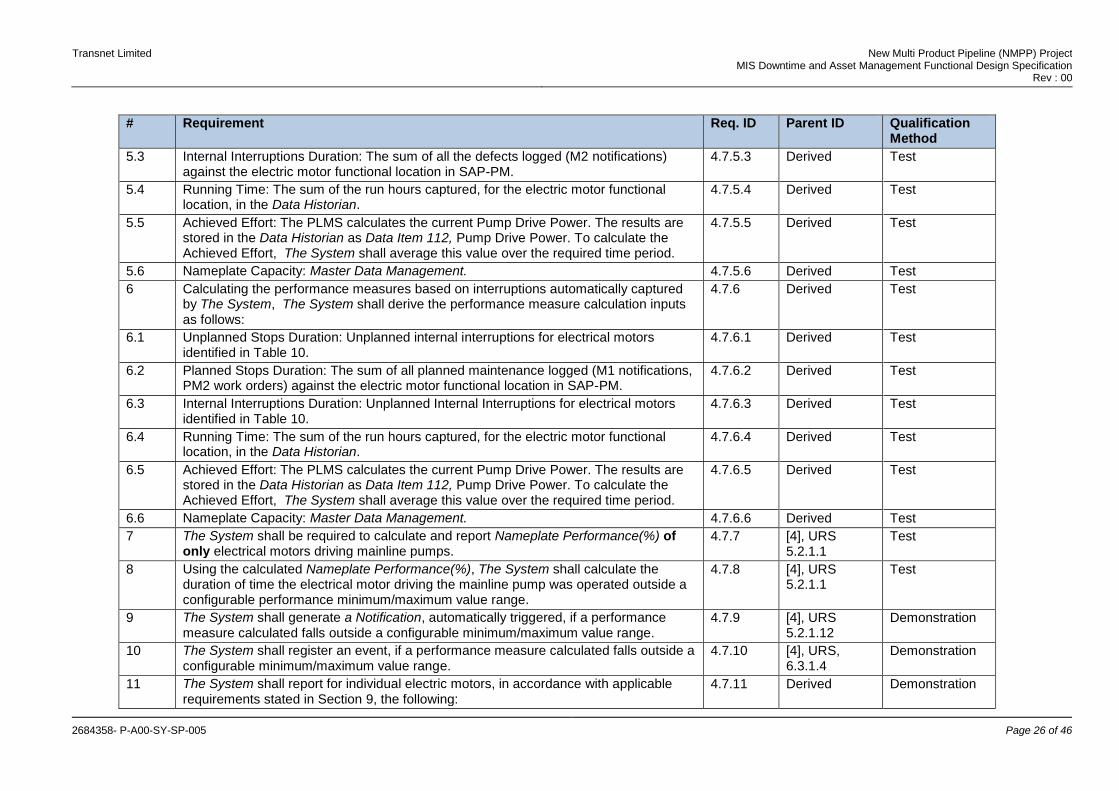
5.3 Internal Interruptions Duration: The sum of all the defects logged (M2 notifications) against the electric motor functional location in SAP-PM.
4.7.5.3 Derived Test
5.4 Running Time: The sum of the run hours captured, for the electric motor functional location, in the Data Historian.
4.7.5.4 Derived Test
5.5 Achieved Effort: The PLMS calculates the current Pump Drive Power. The results are stored in the Data Historian as Data Item 112, Pump Drive Power. To calculate the Achieved Effort, The System shall average this value over the required time period.
4.7.5.5 Derived Test
5.6 Nameplate Capacity: Master Data Management. 4.7.5.6 Derived Test
6 Calculating the performance measures based on interruptions automatically captured by The System, The System shall derive the performance measure calculation inputs as follows:
4.7.6 Derived Test
6.1 Unplanned Stops Duration: Unplanned internal interruptions for electrical motors identified in Table 10.
4.7.6.1 Derived Test
6.2 Planned Stops Duration: The sum of all planned maintenance logged (M1 notifications, PM2 work orders) against the electric motor functional location in SAP-PM.
4.7.6.2 Derived Test
6.3 Internal Interruptions Duration: Unplanned Internal Interruptions for electrical motors identified in Table 10.
4.7.6.3 Derived Test
6.4 Running Time: The sum of the run hours captured, for the electric motor functional location, in the Data Historian.
4.7.6.4 Derived Test
6.5 Achieved Effort: The PLMS calculates the current Pump Drive Power. The results are stored in the Data Historian as Data Item 112, Pump Drive Power. To calculate the Achieved Effort, The System shall average this value over the required time period.
4.7.6.5 Derived Test
6.6 Nameplate Capacity: Master Data Management. 4.7.6.6 Derived Test
7 The System shall be required to calculate and report Nameplate Performance(%) of only electrical motors driving mainline pumps.
4.7.7 [4], URS 5.2.1.1
Test
8 Using the calculated Nameplate Performance(%), The System shall calculate the duration of time the electrical motor driving the mainline pump was operated outside a configurable performance minimum/maximum value range.
4.7.8 [4], URS 5.2.1.1
Test
9 The System shall generate a Notification, automatically triggered, if a performance measure calculated falls outside a configurable minimum/maximum value range.
4.7.9 [4], URS 5.2.1.12
Demonstration
10 The System shall register an event, if a performance measure calculated falls outside a configurable minimum/maximum value range.
4.7.10 [4], URS, 6.3.1.4
Demonstration
11 The System shall report for individual electric motors, in accordance with applicable requirements stated in Section 9, the following:
4.7.11 Derived Demonstration
Transnet Limited New Multi Product Pipeline (NMPP) Project MIS Downtime and Asset Management Functional Design Specification
Rev : 00
2684358- P-A00-SY-SP-005 Page 27 of 46
# Requirement Req. ID Parent ID Qualification Method
11.1 Number of stop/start events 4.7.11.1 Derived Demonstration
11.2 Motor run hours 4.7.11.2 Derived Demonstration
11.3 Operational Availability (%) 4.7.11.3 Derived Demonstration
11.4 Operational Reliability (%) 4.7.11.4 Derived Demonstration
11.5 Utilisation (%) 4.7.11.5 Derived Demonstration
11.6 Nameplate Performance (%) 4.7.11.6 Derived Demonstration
11.7 Unplanned stops duration 4.7.11.7 Derived Demonstration
11.8 Planned stops duration 4.7.11.8 Derived Demonstration
11.9 Internal/External interruptions duration 4.7.11.9 Derived Demonstration
11.10 Achieved effort 4.7.11.10 Derived Demonstration
11.11 Nameplate capacity 4.7.11.11 Derived Demonstration
11.12 The number of motor performance min/max range events 4.7.11.12 Derived Demonstration
11.13 The duration of time the motor was operated outside the performance min/max range 4.7.11.13 Derived Demonstration
12 SAP-PM maintains the cumulative run hours for the electric motors. The System shall at a configurable interval, Automatically Update the SAP-PM cumulative run hours with the run hours accumulated by The System, during the configurable interval.
4.7.12 Derived Demonstration
12.1 The System shall allow the value in the functional location to be Automatically Updated with or without user validation. This behaviour shall be configurable.
4.7.12.1 Derived Demonstration
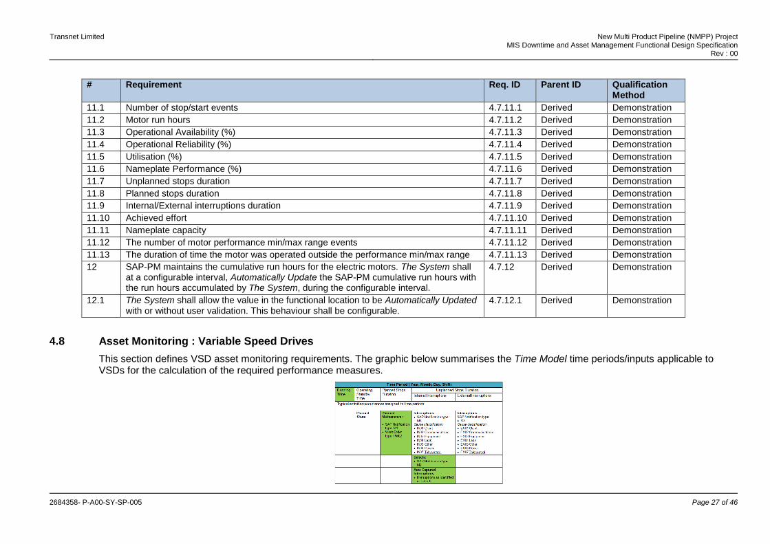
4.8 Asset Monitoring : Variable Speed Drives
This section defines VSD asset monitoring requirements. The graphic below summarises the Time Model time periods/inputs applicable to VSDs for the calculation of the required performance measures.

Transnet Limited New Multi Product Pipeline (NMPP) Project MIS Downtime and Asset Management Functional Design Specification
Rev : 00
2684358- P-A00-SY-SP-005 Page 28 of 46
Table 15 : Asset Monitoring – Variable Speed Drives
# Requirement Req. ID Parent ID Qualification Method
1 The System shall be scalable to monitor, in its end state, the number of VSDs listed in
[2]. This shall include both the existing TPL, NMPP facilities and growth allowance.
4.8.1 Derived Demonstration
2 The System shall Electronically Capture information required to fulfil requirements identified in this section.
4.8.2 Derived Demonstration
3 The System shall calculate, for required VSDs, the following performance measures:
Operational Availability (%)
Operational Reliability (%)
4.8.3 [4], URS 5.2.1.1
Test
3.1 Two sets of performance measure results shall be calculated: 4.8.3.1 Derived Test
3.1.1 One set using interruptions automatically captured by The System. 4.8.3.1.1 Derived Test
3.1.2 One set using interruptions logged in SAP-PM. 4.8.3.1.2 Derived Test
3.2 The calculations shall be done using formula defined in Section 4.2. 4.8.3.2 Derived Test
3.3 The System shall support calculations and aggregations in accordance with applicable requirements stated in Section 9.
4.8.3.3 Derived Test
4 Calculating the performance measures based on interruptions logged in SAP-PM, The System shall derive the performance measure calculation inputs as follows:
4.8.4 Derived Test
4.1 Unplanned Stops Duration: The sum of all the defects logged (M2 notifications) against the VSD functional location in SAP-PM.
4.8.4.1 Derived Test
4.2 Planned Stops Duration: The sum of all planned maintenance logged (M1 notifications, PM2 work orders) against the VSD functional location in SAP-PM.
4.8.4.2 Derived Test
4.3 Internal Interruptions Duration: The sum of all the defects logged (M2 notifications) against the VSD functional location in SAP-PM.
4.8.4.3 Derived Test
5 Calculating the performance measures based on interruptions automatically captured by The System, The System shall derive the performance measure calculation inputs as follows:
4.8.5 Derived Test
5.1 Unplanned Stops Duration: Unplanned internal and external interruptions for VSDs identified in Table 10.
4.8.5.1 Derived Test
5.2 Planned Stops Duration: The sum of all planned maintenance logged (M1 notifications, PM2 work orders) against the VSD functional location in SAP-PM.
4.8.5.2 Derived Test
5.3 Internal Interruptions Duration: Unplanned Interruptions for VSDs identified in Table 10. 4.8.5.3 Derived Test
Transnet Limited New Multi Product Pipeline (NMPP) Project MIS Downtime and Asset Management Functional Design Specification
Rev : 00
2684358- P-A00-SY-SP-005 Page 29 of 46
# Requirement Req. ID Parent ID Qualification Method
6 The System shall generate a Notification, automatically triggered, if a calculated performance measure falls outside a configurable minimum/maximum value range.
4.8.6 [4], URS 5.2.1.12
Demonstration
7 The System shall register an event, if a performance measure calculated falls outside a configurable minimum/maximum value range.
4.8.7 [4], URS, 6.3.1.4
Demonstration
8 The System shall report for individual VSDs, in accordance with applicable requirements stated in Section 9, the following:
4.8.8 Derived Demonstration
8.1 Operational Availability (%) 4.8.8.1 Derived Demonstration
8.2 Operational Reliability (%) 4.8.8.2 Derived Demonstration
8.3 Unplanned stops duration 4.8.8.3 Derived Demonstration
8.4 Planned stops duration 4.8.8.4 Derived Demonstration
8.5 Internal/External interruptions duration 4.8.8.5 Derived Demonstration
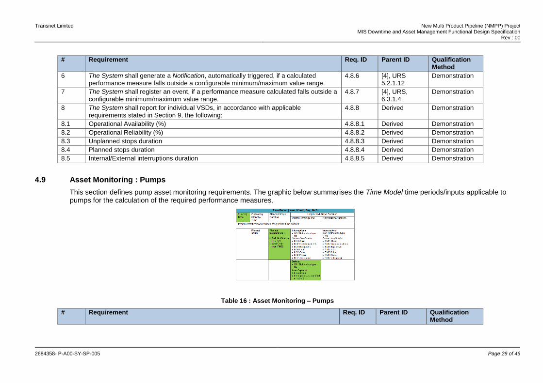
4.9 Asset Monitoring : Pumps
This section defines pump asset monitoring requirements. The graphic below summarises the Time Model time periods/inputs applicable to pumps for the calculation of the required performance measures.
Table 16 : Asset Monitoring – Pumps
# Requirement Req. ID Parent ID Qualification Method
Transnet Limited New Multi Product Pipeline (NMPP) Project MIS Downtime and Asset Management Functional Design Specification
Rev : 00
2684358- P-A00-SY-SP-005 Page 30 of 46
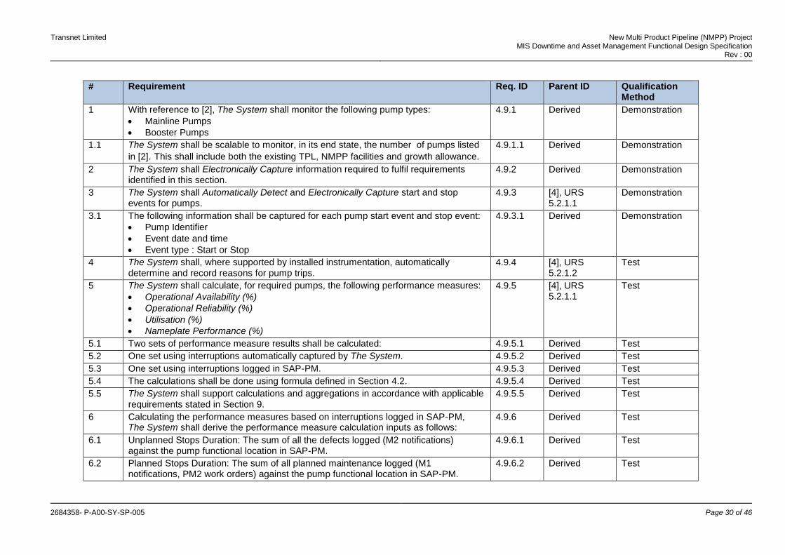
# Requirement Req. ID Parent ID Qualification Method
1 With reference to [2], The System shall monitor the following pump types:
Mainline Pumps
Booster Pumps
4.9.1 Derived Demonstration
1.1 The System shall be scalable to monitor, in its end state, the number of pumps listed
in [2]. This shall include both the existing TPL, NMPP facilities and growth allowance.
4.9.1.1 Derived Demonstration
2 The System shall Electronically Capture information required to fulfil requirements identified in this section.
4.9.2 Derived Demonstration
3 The System shall Automatically Detect and Electronically Capture start and stop events for pumps.
4.9.3 [4], URS 5.2.1.1
Demonstration
3.1 The following information shall be captured for each pump start event and stop event:
Pump Identifier
Event date and time
Event type : Start or Stop
4.9.3.1 Derived Demonstration
4 The System shall, where supported by installed instrumentation, automatically determine and record reasons for pump trips.
4.9.4 [4], URS 5.2.1.2
Test
5 The System shall calculate, for required pumps, the following performance measures:
Operational Availability (%)
Operational Reliability (%)
Utilisation (%)
Nameplate Performance (%)
4.9.5 [4], URS 5.2.1.1
Test
5.1 Two sets of performance measure results shall be calculated: 4.9.5.1 Derived Test
5.2 One set using interruptions automatically captured by The System. 4.9.5.2 Derived Test
5.3 One set using interruptions logged in SAP-PM. 4.9.5.3 Derived Test
5.4 The calculations shall be done using formula defined in Section 4.2. 4.9.5.4 Derived Test
5.5 The System shall support calculations and aggregations in accordance with applicable requirements stated in Section 9.
4.9.5.5 Derived Test
6 Calculating the performance measures based on interruptions logged in SAP-PM, The System shall derive the performance measure calculation inputs as follows:
4.9.6 Derived Test
6.1 Unplanned Stops Duration: The sum of all the defects logged (M2 notifications) against the pump functional location in SAP-PM.
4.9.6.1 Derived Test
6.2 Planned Stops Duration: The sum of all planned maintenance logged (M1 notifications, PM2 work orders) against the pump functional location in SAP-PM.
4.9.6.2 Derived Test
Transnet Limited New Multi Product Pipeline (NMPP) Project MIS Downtime and Asset Management Functional Design Specification
Rev : 00
2684358- P-A00-SY-SP-005 Page 31 of 46
# Requirement Req. ID Parent ID Qualification Method
6.3 Internal Interruptions Duration: The sum of all the defects logged (M2 notifications) against the pump functional location in SAP-PM.
4.9.6.3 Derived Test
6.4 Running Time: The sum of the run hours captured for the pump functional location in the Data Historian.
4.9.6.4 Derived Test
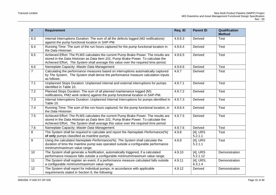
6.5 Achieved Effort: The PLMS calculates the current Pump Brake Power. The results are stored in the Data Historian as Data Item 101, Pump Brake Power. To calculate the Achieved Effort, The System shall average this value over the required time period.
4.9.6.5 Derived Test
6.6 Nameplate Capacity: Master Data Management. 4.9.6.6 Derived Test
7 Calculating the performance measures based on interruptions automatically captured by The System, The System shall derive the performance measure calculation inputs as follows:
4.9.7 Derived Test
7.1 Unplanned Stops Duration: Unplanned internal and external interruptions for pumps identified in Table 10.
4.9.7.1 Derived Test
7.2 Planned Stops Duration: The sum of all planned maintenance logged (M1 notifications, PM2 work orders) against the pump functional location in SAP-PM.
4.9.7.2 Derived Test
7.3 Internal Interruptions Duration: Unplanned Internal Interruptions for pumps identified in Table 10.
4.9.7.3 Derived Test
7.4 Running Time: The sum of the run hours captured, for the pump functional location, in the Data Historian.
4.9.6.4 Derived Test
7.5 Achieved Effort: The PLMS calculates the current Pump Brake Power. The results are stored in the Data Historian as Data Item 101, Pump Brake Power. To calculate the Achieved Effort, The System shall average this value over the required time period.
4.9.7.5 Derived Test
7.6 Nameplate Capacity: Master Data Management. 4.9.7.6 Derived Test
8 The System shall be required to calculate and report the Nameplate Performance(%) of only pumps classified as mainline pumps.
4.9.8 [4], URS 5.2.1.1
Test
9 Using the calculated Nameplate Performance(%), The System shall calculate the duration of time the mainline pump was operated outside a configurable performance minimum/maximum value range.
4.9.9 [4], URS 5.2.1.1
Test
10 The System shall generate a Notification, automatically triggered, if a calculated performance measure falls outside a configurable minimum/maximum value range.
4.9.10 [4], URS 5.2.1.12
Demonstration
11 The System shall register an event, if a performance measure calculated falls outside a configurable minimum/maximum value range.
4.9.11 [4], URS, 6.3.1.4
Demonstration
12 The System shall report for individual pumps, in accordance with applicable requirements stated in Section 9, the following:
4.9.12 Derived Demonstration

Transnet Limited New Multi Product Pipeline (NMPP) Project MIS Downtime and Asset Management Functional Design Specification
Rev : 00
2684358- P-A00-SY-SP-005 Page 32 of 46
# Requirement Req. ID Parent ID Qualification Method
12.1 Number of stop/start events 4.9.12.1 Derived Demonstration
12.2 Pump run hours 4.9.12.2 Derived Demonstration
12.3 Operational Availability (%) 4.9.12.3 Derived Demonstration
11.4 Operational Reliability (%) 4.9.12.4 Derived Demonstration
12.5 Utilisation (%) 4.9.12.5 Derived Demonstration
12.6 Nameplate Performance (%) 4.9.12.6
12.7 Unplanned stops duration 4.9.12.8 Derived Demonstration
12.8 Planned stops duration 4.9.12.9 Derived Demonstration
12.9 Internal/External interruptions duration 4.9.12.10 Derived Demonstration
12.10 The number of pump performance measure min/max range events 4.9.12.11 Derived Demonstration
12.11 The duration of time the pump was operated outside the performance measure min/max range
4.9.12.12 Derived Demonstration
12.12 The number of pump trips 4.9.12.13 Derived Demonstration
12.13 For each trip, the trip reason 4.9.12.14 Derived Demonstration
12.14 Trip reason counts 4.9.12.15 Derived Demonstration
13 SAP-PM maintains the cumulative run hours for the pumps. The System shall at a configurable interval, Automatically Update the SAP-PM cumulative run hours with the run hours accumulated by The System, during the configurable interval.
4.7.13 Derived Demonstration
13.1 The System shall allow the value in the functional location to be Automatically Updated with or without user validation. This behaviour shall be configurable.
4.7.13.1 Derived Demonstration
4.10 Asset Monitoring : Device Groups and Installed Spares
4.10.1 Availability : Device Groups
This section defines the requirements related to the monitoring and reporting of device group availability, as configured in the PCS.
Table 17 : Availability – Device Groups
# Requirement Req. ID Parent ID Qualification Method
1 The System shall be scalable to monitor, in its end state, the number of device
groups listed in [2]. This shall include both the existing TPL, NMPP facilities and growth allowance.
4.10.1.1 Derived Demonstration
Transnet Limited New Multi Product Pipeline (NMPP) Project MIS Downtime and Asset Management Functional Design Specification
Rev : 00
2684358- P-A00-SY-SP-005 Page 33 of 46
# Requirement Req. ID Parent ID Qualification Method
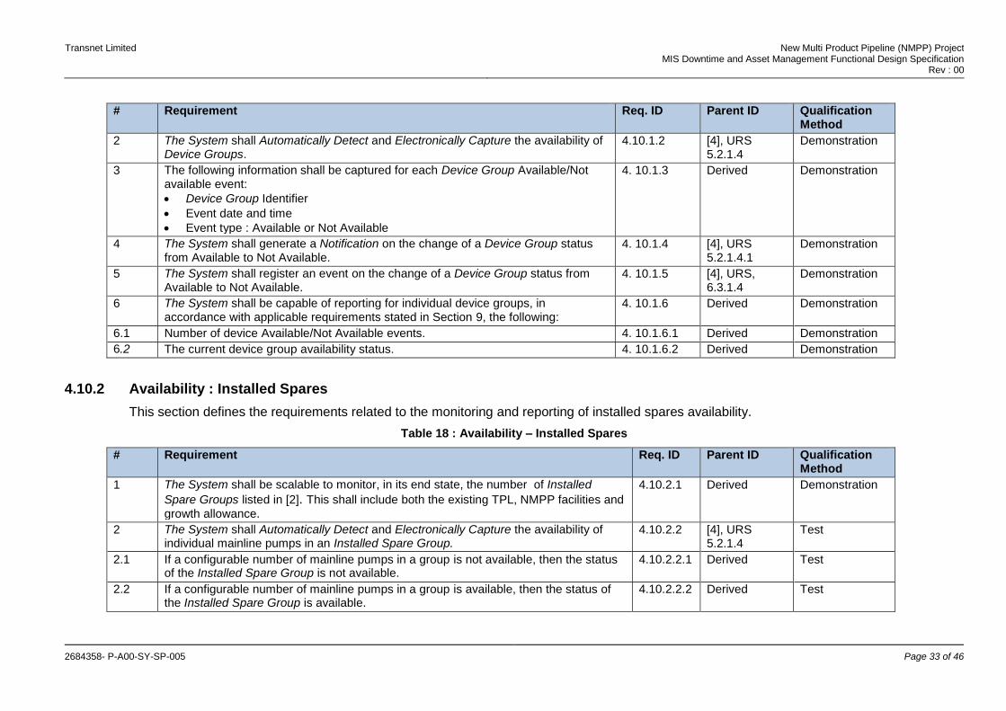
2 The System shall Automatically Detect and Electronically Capture the availability of Device Groups.
4.10.1.2 [4], URS 5.2.1.4
Demonstration
3 The following information shall be captured for each Device Group Available/Not available event:
Device Group Identifier
Event date and time
Event type : Available or Not Available
4. 10.1.3 Derived Demonstration
4 The System shall generate a Notification on the change of a Device Group status from Available to Not Available.
4. 10.1.4 [4], URS 5.2.1.4.1
Demonstration
5 The System shall register an event on the change of a Device Group status from Available to Not Available.
4. 10.1.5 [4], URS, 6.3.1.4
Demonstration
6 The System shall be capable of reporting for individual device groups, in accordance with applicable requirements stated in Section 9, the following:
4. 10.1.6 Derived Demonstration
6.1 Number of device Available/Not Available events. 4. 10.1.6.1 Derived Demonstration
6.2 The current device group availability status. 4. 10.1.6.2 Derived Demonstration
4.10.2 Availability : Installed Spares
This section defines the requirements related to the monitoring and reporting of installed spares availability.
Table 18 : Availability – Installed Spares
# Requirement Req. ID Parent ID Qualification Method
1 The System shall be scalable to monitor, in its end state, the number of Installed
Spare Groups listed in [2]. This shall include both the existing TPL, NMPP facilities and
growth allowance.
4.10.2.1 Derived Demonstration
2 The System shall Automatically Detect and Electronically Capture the availability of individual mainline pumps in an Installed Spare Group.
4.10.2.2 [4], URS 5.2.1.4
Test
2.1 If a configurable number of mainline pumps in a group is not available, then the status of the Installed Spare Group is not available.
4.10.2.2.1 Derived Test
2.2 If a configurable number of mainline pumps in a group is available, then the status of the Installed Spare Group is available.
4.10.2.2.2 Derived Test

Transnet Limited New Multi Product Pipeline (NMPP) Project MIS Downtime and Asset Management Functional Design Specification
Rev : 00
2684358- P-A00-SY-SP-005 Page 34 of 46
# Requirement Req. ID Parent ID Qualification Method
3 The following information shall be captured for each Installed Spare Group Available/Not available event:
Installed Spare Group Identifier.
Event date and time.
Event type : Available or Not Available.
4.10.2.3 Derived Demonstration
4 The System shall generate a Notification on the change of an Installed Spare Group from Available to Not Available.
4.10.2.4 [4], URS 5.2.1.4.1
Demonstration
5 The System shall register an event on the change of an Installed Spare Group status from Available to Not Available.
4.10.2.5 [4], URS, 6.3.1.4
Demonstration
6 The System shall calculate, for Installed Spare Groups, the following performance measures:
Installed Spare Group Availability(%)
4.10.2.6
7 The System shall report for individual Installed Spare Groups, in accordance with applicable requirements stated in Section 9, the following:
4.10.2.7 Derived Demonstration
7.1 Number of group Available/Not Available events. 4.10.2.7.1 Derived Demonstration
7.2 Installed Spare Group Availability(%). 4.10.2.7.2 Derived Demonstration
7.3 Current Installed Spare Group status. 4.10.2.7.3 Derived Demonstration
4.11 Asset Monitoring : Instrument Status
This section defines the requirements related to instrument health/status reporting.
Table 19 : Asset Monitoring – Instrument Status
# Requirement Req. ID Parent ID Qualification Method
1 The System shall be scalable to monitor, in its end state, the number of Instruments
listed in [2]. This shall include both the existing TPL, NMPP facilities and growth
allowance.
4.11.1 Derived Demonstration
2 The System shall report instrument status conditions. Typical status conditions are:
Hardware Fault.
Operator Override.
Communications Error
4.11.2 Derived Demonstration
3 It shall be possible to configure equipment status conditions to be reported. 4.11.3 Derived Demonstration
Transnet Limited New Multi Product Pipeline (NMPP) Project MIS Downtime and Asset Management Functional Design Specification
Rev : 00
2684358- P-A00-SY-SP-005 Page 35 of 46
# Requirement Req. ID Parent ID Qualification Method
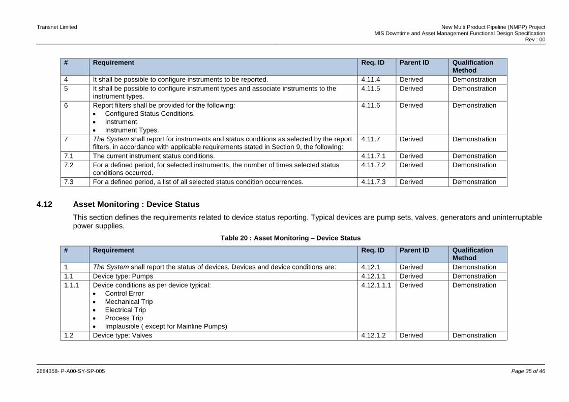
4 It shall be possible to configure instruments to be reported. 4.11.4 Derived Demonstration
5 It shall be possible to configure instrument types and associate instruments to the instrument types.
4.11.5 Derived Demonstration
6 Report filters shall be provided for the following:
Configured Status Conditions.
Instrument.
Instrument Types.
4.11.6 Derived Demonstration
7 The System shall report for instruments and status conditions as selected by the report filters, in accordance with applicable requirements stated in Section 9, the following:
4.11.7 Derived Demonstration
7.1 The current instrument status conditions. 4.11.7.1 Derived Demonstration
7.2 For a defined period, for selected instruments, the number of times selected status conditions occurred.
4.11.7.2 Derived Demonstration
7.3 For a defined period, a list of all selected status condition occurrences. 4.11.7.3 Derived Demonstration
4.12 Asset Monitoring : Device Status
This section defines the requirements related to device status reporting. Typical devices are pump sets, valves, generators and uninterruptable power supplies.
Table 20 : Asset Monitoring – Device Status
# Requirement Req. ID Parent ID Qualification Method
1 The System shall report the status of devices. Devices and device conditions are: 4.12.1 Derived Demonstration
1.1 Device type: Pumps 4.12.1.1 Derived Demonstration
1.1.1 Device conditions as per device typical:
Control Error
Mechanical Trip
Electrical Trip
Process Trip
Implausible ( except for Mainline Pumps)
4.12.1.1.1 Derived Demonstration
1.2 Device type: Valves 4.12.1.2 Derived Demonstration
Transnet Limited New Multi Product Pipeline (NMPP) Project MIS Downtime and Asset Management Functional Design Specification
Rev : 00
2684358- P-A00-SY-SP-005 Page 36 of 46
# Requirement Req. ID Parent ID Qualification Method
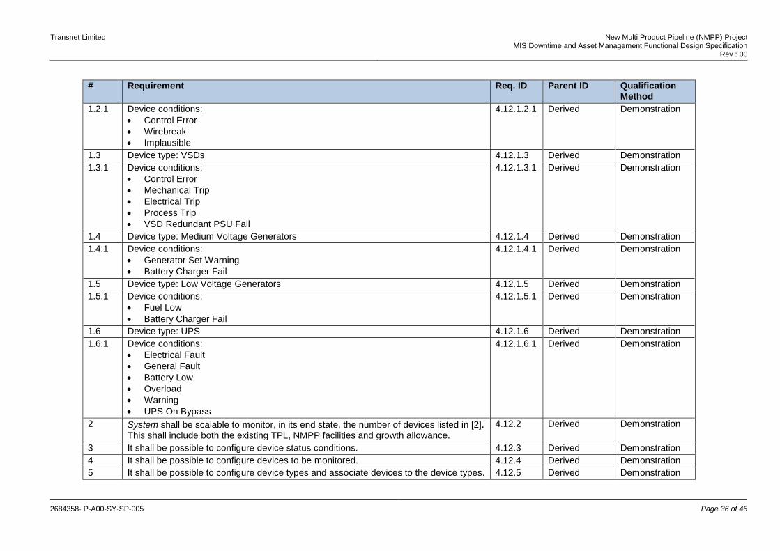
1.2.1 Device conditions:
Control Error
Wirebreak
Implausible
4.12.1.2.1 Derived Demonstration
1.3 Device type: VSDs 4.12.1.3 Derived Demonstration
1.3.1 Device conditions:
Control Error
Mechanical Trip
Electrical Trip
Process Trip
VSD Redundant PSU Fail
4.12.1.3.1 Derived Demonstration
1.4 Device type: Medium Voltage Generators 4.12.1.4 Derived Demonstration
1.4.1 Device conditions:
Generator Set Warning
Battery Charger Fail
4.12.1.4.1 Derived Demonstration
1.5 Device type: Low Voltage Generators 4.12.1.5 Derived Demonstration
1.5.1 Device conditions:
Fuel Low
Battery Charger Fail
4.12.1.5.1 Derived Demonstration
1.6 Device type: UPS 4.12.1.6 Derived Demonstration
1.6.1 Device conditions:
Electrical Fault
General Fault
Battery Low
Overload
Warning
UPS On Bypass
4.12.1.6.1 Derived Demonstration
2 System shall be scalable to monitor, in its end state, the number of devices listed in [2]. This shall include both the existing TPL, NMPP facilities and growth allowance.
4.12.2 Derived Demonstration
3 It shall be possible to configure device status conditions. 4.12.3 Derived Demonstration
4 It shall be possible to configure devices to be monitored. 4.12.4 Derived Demonstration
5 It shall be possible to configure device types and associate devices to the device types. 4.12.5 Derived Demonstration
Transnet Limited New Multi Product Pipeline (NMPP) Project MIS Downtime and Asset Management Functional Design Specification
Rev : 00
2684358- P-A00-SY-SP-005 Page 37 of 46
# Requirement Req. ID Parent ID Qualification Method
6 Report filters shall be provided for the following:
Configured device conditions.
Device.
Device Types.
4.12.6 Derived Demonstration
7 The System shall report for instruments and status conditions as selected by the report filters, in accordance with applicable requirements stated in Section 9, the following:
4.12.7 Derived Demonstration
7.1 The current device status conditions. 4.12.7.1 Derived Demonstration
7.2 For a defined period, for selected devices, the number of times the selected status conditions occurred.
4.12.7.2 Derived Demonstration
7.3 For a defined period, a list of all selected status condition occurrences. 4.12.7.3 Derived Demonstration
4.13 Asset Monitoring : Plant and Process Performance Monitoring
This section defines the asset monitoring requirements related to pump stations and pipelines. The graphic below summarises the Time Model time periods/inputs applicable to pump stations and pipelines for the calculation of the required performance measures.
Table 21 : Asset Monitoring – Plant and Process Performance Monitoring
# Requirement Req. ID Parent ID Qualification Method

Transnet Limited New Multi Product Pipeline (NMPP) Project MIS Downtime and Asset Management Functional Design Specification
Rev : 00
2684358- P-A00-SY-SP-005 Page 38 of 46
# Requirement Req. ID Parent ID Qualification Method
1 System shall be scalable to monitor, in its end state, the number of stations and
pipelines in listed [2]. This shall include both the existing TPL, NMPP facilities and growth allowance.
4.13.1 Derived Demonstration
2 The System shall Electronically Capture information required to fulfil requirements identified in this section.
4.13.2 Derived Demonstration
3 The System shall calculate, for required stations and pipelines, the following performance measures:
Operational Availability (%)
Operational Reliability (%)
Planned Availability (%)
4.13.3 [4], URS 5.2.1.1
Test
3.1 The calculations shall be done using formula defined in Section 4.2. 4.13.3.1 Derived Test
3.2 Two sets of performance measure results shall be calculated: 4.13.3.2 Derived Test
3.3 One set using interruptions automatically captured by The System. 4.13.3.3 Derived Test
3.4 One set using interruptions logged in SAP-PM. 4.13.3.4 Derived Test
3.5 The System shall support calculations and aggregations in accordance with applicable requirements stated in Section 9.
4.13.3.5 Derived Test
4 Calculating the performance measures based on interruptions logged in SAP-PM, The System shall derive the performance measure calculation inputs as follows:
4.13.4 Derived Test
4.1 Unplanned Stops Duration: The sum of all the internal and external interruptions logged (M8 notifications, INxx and EXxx cause classification) against the relevant functional location in SAP-PM.
4.13.4.1 Derived Test
4.2 Planned Stops Duration: The sum of all planned maintenance logged (M1 notifications, PM2 work orders) against the station or pipeline functional location in SAP-PM.
4.13.4.2 Derived Test
4.3 Internal Interruptions Duration: The sum of the internal interruptions (M8 notifications, INx cause classification) against the relevant functional location in SAP-PM.
4.13.4.3 Derived Test
5 Calculating the performance measures based on interruptions automatically captured by The System, The System shall derive the performance measure calculation inputs as follows:
4.13.5 Derived Test
5.1 Unplanned Stops Duration: Unplanned Internal and External Interruptions for stations and pipelines identified in Table 10.
4.13.5.1 Derived Test
5.2 Planned Stops Duration: The sum of all planned maintenance logged (M1 notifications, PM2 work orders) against the station or pipeline functional location in SAP-PM.
4.13.5.2 Derived Test
5.3 Internal Interruptions Duration: Unplanned internal and external interruptions for stations and pipelines identified in Table 10.
4.13.5.3 Derived Test
Transnet Limited New Multi Product Pipeline (NMPP) Project MIS Downtime and Asset Management Functional Design Specification
Rev : 00
2684358- P-A00-SY-SP-005 Page 39 of 46
# Requirement Req. ID Parent ID Qualification Method
6 The System shall generate a Notification, automatically triggered, if a performance measure calculated falls outside a configurable minimum/maximum value range.
4.13.6 [4], URS 5.2.1.12
Demonstration
6.1 The System shall register an event, if a performance measure calculated falls outside a configurable minimum/maximum value range.
4.13.6.1 [4], URS, 6.3.1.4
Demonstration
7 The System shall report for individual stations and pipelines, in accordance with applicable requirements stated in Section 9, the following:
4.13.7 Derived Demonstration
7.1 Operational Availability (%) 4.13.7.1 Derived Demonstration
7.2 Operational Reliability (%) 4.13.7.2 Derived Demonstration
7.3 Planned Availability (%) 4.13.7.3 Derived Demonstration
7.4 Unplanned stops duration 4.13.7.5 Derived Demonstration
7.5 Planned stops duration 4.13.7.6 Derived Demonstration
7.6 Internal interruptions duration 4.13.7.7 Derived Demonstration
7.7 The number of pipeline/station performance min/max range events 4.13.7.8 Derived Demonstration
7.8 The duration of time the pipeline/station was operated outside the performance min/max range
4.13.7.9 Derived Demonstration
4.14 Asset Monitoring : Diagnostic Dashboard
This section defines the requirements related to the provision of a process control system diagnostic dashboard.
Table 22 : Asset Monitoring – Diagnostic Dashboard
# Requirement Req. ID Parent ID Qualification Method
1 For the Process Control System, The System shall provide a Diagnostic Dashboard focussed on the following information:
Controller load analysis.
Status of terminal and system bus redundancy.
Diagnostic information on network ( bus load, bursts, data frame loss, etc.).
Diagnostic information on the process control network such as bus load, bursts, data frame loss.
PCS server and workstation errors.
Controller status registers where provisioned by the controller
4.12.1 [4], URS 5.2.1.15
Demonstration

Transnet Limited New Multi Product Pipeline (NMPP) Project MIS Downtime and Asset Management Functional Design Specification
Rev : 00
2684358- P-A00-SY-SP-005 Page 40 of 46
4.15 Event Classification
This section identifies requirements associated with the classification of events captured by The System.
Table 23 : Event Classification
# Requirement Req. ID Parent ID Qualification Method
1 The System shall automatically assign an event type classification to events captured. 4.15.1 Derived Demonstration
1.1 The System shall provide functionality whereby an event type can be associated with each event condition monitored.
4.15.1.1 Derived Demonstration
1.2 The System shall provide a mechanism whereby the use of an event type can be disabled. Thus it shall not be possible to associate a disabled event type to a monitored event condition.
4.15.1.2 Derived Demonstration
1.3 The System shall allow users, with the appropriate access rights, to change the automatically assigned event type classification.
4.15.1.3 Derived Demonstration
1.4 The System shall maintain an audit trail of all classification changes made. 4.15.1.4 Derived Demonstration
2 It shall be possible to configure event types. 4.15.2 Derived Demonstration
3 Each event type shall have the following attributes as a minimum:
Unique identifier.
Name.
Description.
4.15.3 Derived Demonstration
4 It shall be possible to modify the event type Name and Description attributes. 4.15.4 Derived Demonstration
5 It shall not be possible to delete an event type. 4.15.5 Derived Demonstration
5. Maintenance Management Requirements
5.1 Maintenance Scheduling
This section identifies maintenance scheduling requirements.
Table 24 : Maintenance Scheduling Requirements
# Requirement Req. ID Parent ID Qualification Method

Transnet Limited New Multi Product Pipeline (NMPP) Project MIS Downtime and Asset Management Functional Design Specification
Rev : 00
2684358- P-A00-SY-SP-005 Page 41 of 46
# Requirement Req. ID Parent ID Qualification Method
1 The TPL SAP-PM system shall be configured to allow users to schedule inspections on the following classes of equipment:
Storage and accumulator tanks.
Lifting equipment.
Pressure vessels.
Provers.
5.1.1 [4], URS 5.2.1.9
Demonstration
1.1 The TPL SAP-PM system shall generate work orders for the schedule inspections. 5.1.1.1 Derived Demonstration
1.2 The System shall provide users with a report identifying which inspections are due within a specified period.
5.1.1.2 [4], URS 5.2.1.9.1
Demonstration
1.3 The System shall provide users with a report identifying which inspections were not completed within the scheduled period.
5.1.1.3 [4], URS 5.2.1.9.2
Demonstration
1.4 The System shall allow users to load inspection reports onto the system and to associate the loaded inspection report with the inspection SAP work order.
5.1.1.4 [4], URS 5.2.1.9.3
Demonstration
5.2 Maintenance Reporting and Analysis
This section identifies maintenance reporting and analysis requirements.
Table 25 : Maintenance Reporting and Analysis Requirements
# Requirement Req. ID Parent ID Qualification Method
1 The System shall provide a report detailing the number of times a component has been replaced in a user defined period of time.
5.2.1 [4], URS 5.2.1.8
Demonstration
2 The System shall calculate the MTBF of the following classes of equipment:
Motors
Valves
5.2.2 [4], URS 5.2.1.10
Demonstration
2.1 The MTBF shall be calculated for a specific functional location defined in SAP-PM. 5.2.2.1 Derived Test
2.2 The MTBF shall be calculated for a specific equipment serial number. 5.2.2.2 Derived Test
2.3 MTBF shall be calculated as follows: MTBF = Total operating time in defined period / number of failures in the period.
5.2.2.3 Derived Test
3 Where required, The System shall extract component/equipment records from the TPL SAP-PM system.
5.2.3 Derived Demonstration
Transnet Limited New Multi Product Pipeline (NMPP) Project MIS Downtime and Asset Management Functional Design Specification
Rev : 00
2684358- P-A00-SY-SP-005 Page 42 of 46
6. Organisational Plant/Process Modelling Requirements
This section identifies plant and process modelling requirements.
Table 26 : Plant/Process Modelling Requirements
# Requirement Req. ID Parent ID Qualification Method
1 For the purposes of asset monitoring, it shall be possible to define models/structures against which to calculate, summarise and report the following measures for the process, plant and equipment:
Operational availability (%)
Operational reliability (%)
Utilisation (%)
Performance (%)
Planned Stops Duration
Unplanned Stops Duration
Internal Interruptions Duration
Running Time
Achieved Effort Using the ISA 95 Equipment Hierarchy Model as an example, it shall be possible to calculate and report process, plant and equipment performance at Enterprise, Site, Area, Process Cell and Unit Level. For the purposes of this requirement, the ISA 95 model shall be further extended to include lower level equipment such as equipment modules, sensors and actuators were applicable.
6.1 [4], URS 5.2.1.3
Demonstration
2 It shall be possible to associate elements in the models/structures with their respective SAP-PM functional locations and SAP-PM Work Centres..
6.2 Derived Demonstration
7. Bentley Nevada Integration
This section identifies integration requirements with the Bentley Nevada machine monitoring system.
Table 27 : Bentley Nevada Integration
# Requirement Req. ID Parent ID Qualification Method

Transnet Limited New Multi Product Pipeline (NMPP) Project MIS Downtime and Asset Management Functional Design Specification
Rev : 00
2684358- P-A00-SY-SP-005 Page 43 of 46
# Requirement Req. ID Parent ID Qualification Method
1 The System shall provide access to data captured and maintained by Bentley Nevada at local/remote sites.
7.1 [4], URS 5.2.1.6
Demonstration
2 The System shall generate a Notification, automatically triggered by the outcome of equipment and instrument monitoring evaluations performed by the TPL Bentley Nevada system.
7.2 [4], URS 5.2.1.12.1
Demonstration
2.1 The System shall register an event, automatically triggered by the outcome of equipment and instrument monitoring evaluations performed by the TPL Bentley Nevada system.
7.2.1 [4], URS, 6.3.1.4
Demonstration
3 The System shall report, in accordance with applicable requirements stated in Section 9, the following for individual equipment and instrument monitoring evaluations:
7.3 Derived Demonstration
3.1 Number of evaluation notifications generated. 7.3.1 Derived Demonstration
8. Ad-hoc Investigation Data/Results Management
This section identifies requirements related to ad-hoc investigation data and results management.
Table 28 : Ad-hoc Investigation Data/Results Management
# Requirement Req. ID Parent ID Qualification Method
1 The System shall manage data collected during ad-hoc investigations. Typically, moveable sensors are installed for a period of time and the data is logged to a laptop.
8.1 [4], URS 5.2.1.14
Demonstration
9. Calculation and Reporting Requirements
This section defines generic calculation and reporting requirements for the functional areas identified in this specification.
Table 29 : Reporting Requirements
# Requirement Req. ID Parent ID Qualification Method
1 The System shall support the calculation and reporting of parameters identified in applicable sections of this specification as follows:
9.1 Derived Demonstration
Transnet Limited New Multi Product Pipeline (NMPP) Project MIS Downtime and Asset Management Functional Design Specification
Rev : 00
2684358- P-A00-SY-SP-005 Page 44 of 46
# Requirement Req. ID Parent ID Qualification Method
1.1 The calculations and aggregations for the following time periods:
Year
Month
Day
Shift
9.1.1 Derived Demonstration
1.2 Calculation, were applicable, of the following values:
Year to date
Month to date
Day to date
Shift to date
9.1.2 Derived Demonstration
1.3 Reporting based on user defined/selectable reporting periods. 9.1.3 Derived Demonstration
10. Disconnected Operations
The System will be deployed at various facilities geographically dispersed throughout the country and network/communications connectivity is not always ensured. This section identifies requirements related to the disconnected state of operations. The requirements are stated from a user interaction perspective and from a system component perspective.
Table 30 : Disconnected Operations
# Requirement Req. ID Parent ID Qualification Method
1 Given that the user has an operable device, the user shall be able to do the following in a disconnected state:
10.1 Derived Demonstration
1.1 Manually capture required information 10.1.1 Derived Demonstration
1.2 Manually create notifications/events 10.1.2
2 The System shall support the following in a disconnected state: 10.2 Derived Demonstration
2.1 Notifications to or from a disconnected facility shall be queued for delivery until the connection is restored.
10.2.1 Derived Demonstration
2.2 Events generated at a disconnected site shall be queued for delivery until the connection is restored.
10.2.2 Derived Demonstration
11. Configuration Principles
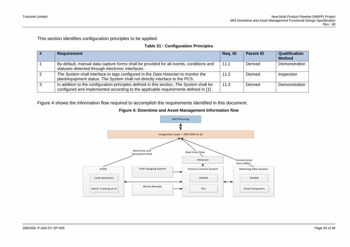
Transnet Limited New Multi Product Pipeline (NMPP) Project MIS Downtime and Asset Management Functional Design Specification
Rev : 00
2684358- P-A00-SY-SP-005 Page 45 of 46
This section identifies configuration principles to be applied.
Table 31 : Configuration Principles
# Requirement Req. ID Parent ID Qualification Method
1 By default, manual data capture forms shall be provided for all events, conditions and statuses detected through electronic interfaces.
11.1 Derived Demonstration
2 The System shall interface to tags configured in the Data Historian to monitor the plant/equipment status. The System shall not directly interface to the PCS.
11.2 Derived Inspection
3 In addition to the configuration principles defined in this section, The System shall be configured and implemented according to the applicable requirements defined in [1] .
11.3 Derived Demonstration
Figure 4 shows the information flow required to accomplish the requirements identified in this document.
Figure 4: Downtime and Asset Management Information flow
Process Control System
SCADA
PLC
Metering Data System
SCADA
Flow Computers
Tank Gauging System
Historian
SAP/Planning
PLMS
Leak Detection
Batch Tracking et al
Integration Layer – MES (MII et al)
Real-time and Geospatial Data
Real-time Data
Transactional Data (XML)
Bently Nevada
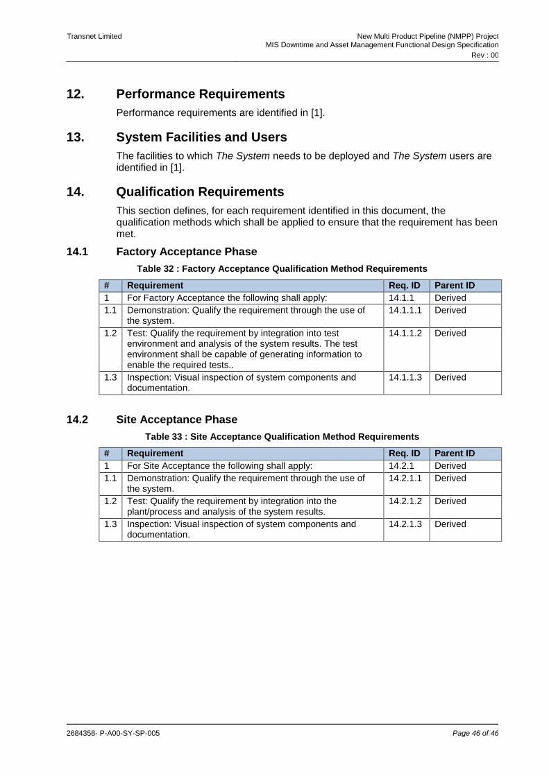
Transnet Limited New Multi Product Pipeline (NMPP) Project MIS Downtime and Asset Management Functional Design Specification
Rev : 00
2684358- P-A00-SY-SP-005 Page 46 of 46
12. Performance Requirements
Performance requirements are identified in [1].
13. System Facilities and Users
The facilities to which The System needs to be deployed and The System users are identified in [1].
14. Qualification Requirements
This section defines, for each requirement identified in this document, the qualification methods which shall be applied to ensure that the requirement has been met.
14.1 Factory Acceptance Phase
Table 32 : Factory Acceptance Qualification Method Requirements
# Requirement Req. ID Parent ID
1 For Factory Acceptance the following shall apply: 14.1.1 Derived
1.1 Demonstration: Qualify the requirement through the use of the system.
14.1.1.1 Derived
1.2 Test: Qualify the requirement by integration into test environment and analysis of the system results. The test environment shall be capable of generating information to enable the required tests..
14.1.1.2 Derived
1.3 Inspection: Visual inspection of system components and documentation.
14.1.1.3 Derived
14.2 Site Acceptance Phase
Table 33 : Site Acceptance Qualification Method Requirements
# Requirement Req. ID Parent ID
1 For Site Acceptance the following shall apply: 14.2.1 Derived
1.1 Demonstration: Qualify the requirement through the use of the system.
14.2.1.1 Derived
1.2 Test: Qualify the requirement by integration into the plant/process and analysis of the system results.
14.2.1.2 Derived
1.3 Inspection: Visual inspection of system components and documentation.
14.2.1.3 Derived