Embed Size (px)
Citation preview
TPR UniLock™
PATENT PENDING
Truck Restraint
Owner’s/User’s Manual
Printed in U.S.A.Copyright © 2017
Manual No. 4111-0072 Nov. 2017
POWERAMP • Division of Systems, Inc. • W194 N11481 McCormick Drive • Germantown, WI 53022800.643.5424 • fax: 262.255.5917 • www.poweramp.com • [email protected]
PagePrecautionsRecognize Precautionary Information ...................................................... 1General Operational Precautions .............................................................. 1Maintenance Precautions .......................................................................... 4Precautionary Decals .................................................................................. 5Owner’s/User’s Responsibilities................................................................ 6
IntroductionGeneral Information .................................................................................... 8Component Identification ........................................................................... 9
InstallationInstallation Roller Track .............................................................................10Installation Carriage ...................................................................................12Component Locations .............................................................................. 14Installation Placard ................................................................................... 15Electrical Schematics ............................................................................... 16
OperationOperating Instructions .............................................................................. 18Sequence of Operation ............................................................................. 19
MaintenanceService Dock Leveler/Restraint .............................................................. 22Periodic Maintenance ............................................................................... 23
AdjustmentDrive Chain ............................................................................................... 24Brake Torque ............................................................................................. 24
TroubleshootingTroubleshooting Charts ............................................................................ 25Limit Switches ........................................................................................... 26Harness ...................................................................................................... 28
PartsControl Box/Lights/Signs ......................................................................... 29Assembly Components ............................................................................ 30Roller Track and Springs.......................................................................... 32Carriage Assembly .................................................................................... 33Outside Light Assy.12VDC ....................................................................... 34
MiscellaneousPlacard ....................................................................................................... 35Inside/Outside Caution Signs, Mirror ...................................................... 36Customer Information ............................................................................... 37Warranty ..................................................................................... Back Cover
Table of Contents
14111-0072— Nov. 2017
PRECAUTIONS
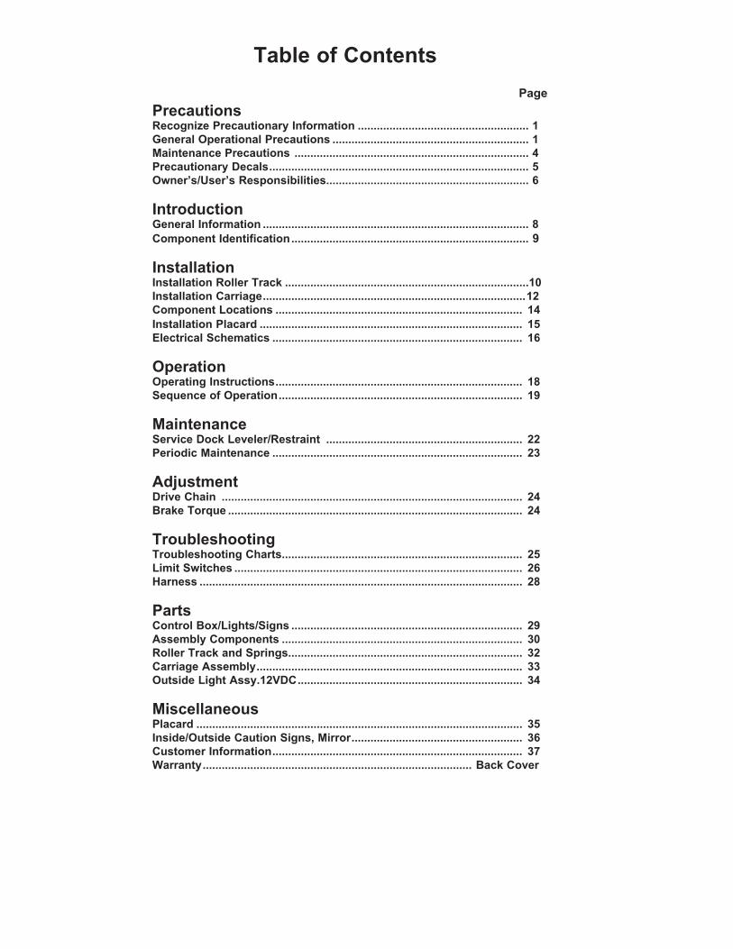
The use of the word DANGER signifies the presence of an extreme hazard or unsafe practice which will most likely result in death or severe injury.
The use of the word WARNING signifies the presence of a serious hazard or unsafe practice which could result in death or serious injury.
The use of the word CAUTION signifies possible hazard or unsafe practice which could result in minor or moderate injury.
Do not start the equipment until all unauthorized personnel in the area have been warned and have moved outside the operating zone.
Remove any tools or foreign objects from the operating zone before starting.
Keep the operating zone free of obstacles that could cause a person to trip or fall.
Read and understand the Owner’s/User’s Manual and become thoroughly familiar with the equipment and its controls before operating the transport vehicle restraint.
Never operate a transport vehicle restraint while a safety device or guard is removed or disconnected.
Never remove DANGER, WARNING, or CAUTION signs, Placards or Decals on the equipment unless replacing them.
General Operational PrecautionsRecognize Precautionary Information
The Safety-Alert Symbol is a graphic representation intended to convey a safety message without the use of words. When you see this symbol, be alert to the possibility of death or serious injury. Follow the instructions in the safety message panel.
Safety - Alert Symbol
The use of the word NOTICE indicates information considered important, but not hazard-related, to prevent machine or property damage.
Operating Zone
Operating Zone
Indicates a type of safety sign, or separate panel on a safety sign, where safety-related instructions or procedures as described.
2 4111-0072 — Nov. 2017
PRECAUTIONS
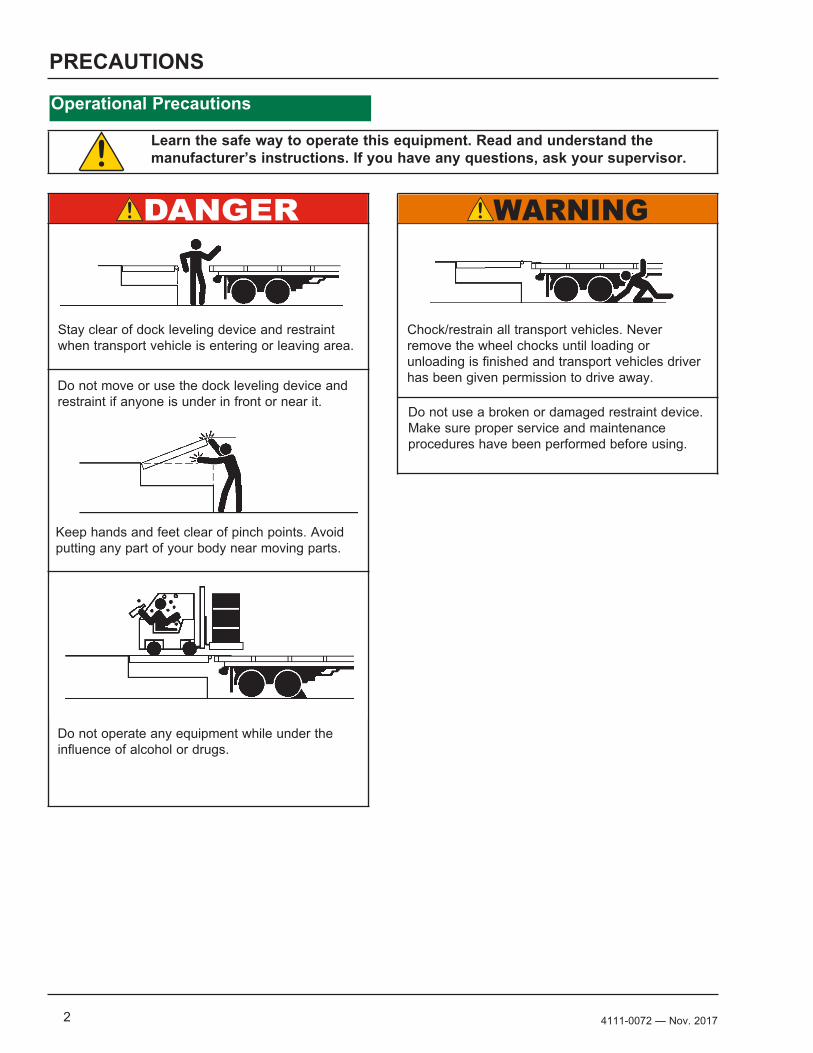
Operational Precautions
Stay clear of dock leveling device and restraint when transport vehicle is entering or leaving area.
Do not move or use the dock leveling device and restraint if anyone is under in front or near it.
Keep hands and feet clear of pinch points. Avoid putting any part of your body near moving parts.
Chock/restrain all transport vehicles. Never remove the wheel chocks until loading or unloading is finished and transport vehicles driver has been given permission to drive away.
Do not use a broken or damaged restraint device. Make sure proper service and maintenance procedures have been performed before using.
Do not operate any equipment while under the influence of alcohol or drugs.
Learn the safe way to operate this equipment. Read and understand the manufacturer’s instructions. If you have any questions, ask your supervisor.

34111-0072— Nov. 2017
PRECAUTIONS
This page intentionally left blank
4 4111-0072 — Nov. 2017
PRECAUTIONS
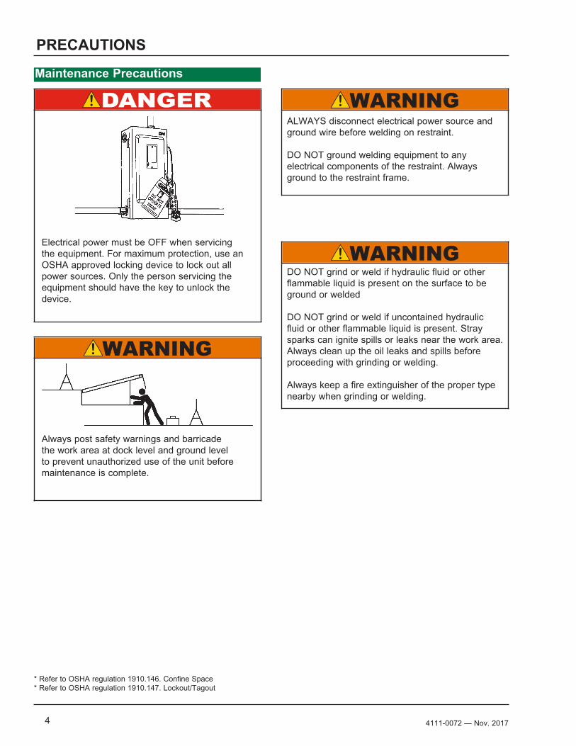
Maintenance Precautions
* Refer to OSHA regulation 1910.146. Confine Space* Refer to OSHA regulation 1910.147. Lockout/Tagout
ALWAYS disconnect electrical power source and ground wire before welding on restraint.
DO NOT ground welding equipment to any electrical components of the restraint. Always ground to the restraint frame.
DO NOT grind or weld if hydraulic fluid or other flammable liquid is present on the surface to be ground or welded
DO NOT grind or weld if uncontained hydraulic fluid or other flammable liquid is present. Stray sparks can ignite spills or leaks near the work area. Always clean up the oil leaks and spills before proceeding with grinding or welding.
Always keep a fire extinguisher of the proper type nearby when grinding or welding.
Electrical power must be OFF when servicing the equipment. For maximum protection, use an OSHA approved locking device to lock out all power sources. Only the person servicing the equipment should have the key to unlock the device.
Always post safety warnings and barricade the work area at dock level and ground level to prevent unauthorized use of the unit before maintenance is complete.
54111-0072— Nov. 2017
PRECAUTIONSRestraint Precautionary Decals
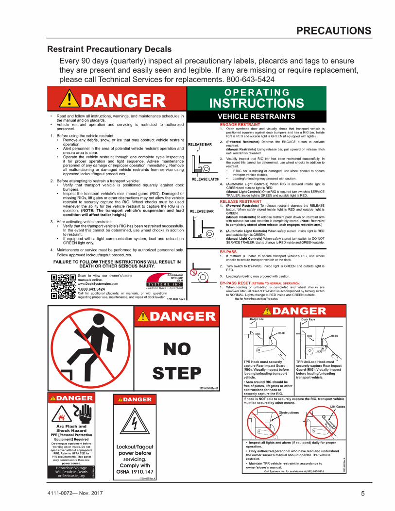
Every 90 days (quarterly) inspect all precautionary labels, placards and tags to ensure they are present and easily seen and legible. If any are missing or require replacement, please call Technical Services for replacements. 800-643-5424
1.50"
3.0
0"
Decal Size: 1.5 x 3File Name: 1751-0736 Rev A
Arc Flash andShock Hazard
PPE [Personal Protection Equipment] Required
De-energize equipment before working on or inside. Do not
open cover without appropriate PPE. Refer to NFPA 70E for
PPE requirements. This panel may contain more than one
power source.
Hazardous VoltageWill Result in Death
or Serious Injury 1751
-0736
Rev
A
File Name: 1751-0149 REV BDecal Size: 5 x 2.5
NO STEP
1751-0149 Rev B
O P E R AT I N GINSTRUCTIONSDANGER
• Read and follow all instructions, warnings, and maintenance schedules in the manual and on placards.
• Vehicle restraint operation and servicing is restricted to authorized personnel.
1. Before using the vehicle restraint:• Remove any debris, snow, or ice that may obstruct vehicle restraint
operation.• Alert personnel in the area of potential vehicle restraint operation and
ensure area is clear.• Operate the vehicle restraint through one complete cycle inspecting
it for proper operation and light sequence. Advise maintenance personnel of any damage or improper operation immediately. Remove all malfunctioning or damaged vehicle restraints from service using approved lockout/tagout procedures.
2. Before attempting to restrain a transport vehicle:• Verify that transport vehicle is positioned squarely against dock
bumpers.• Inspect the transport vehicle’s rear impact guard (RIG). Damaged or
missing RIGs, lift gates or other obstructions may not allow the vehicle restraint to securely capture the RIG. Wheel chocks must be used whenever the ability for the vehicle restraint to capture the RIG is in question. (NOTE: The transport vehicle’s suspension and load condition will affect trailer height.)
3. After activating vehicle restraint:• Verify that the transport vehicle’s RIG has been restrained successfully.
In the event this cannot be determined, use wheel chocks in addition to restraint.
• If equipped with a light communication system, load and unload on GREEN light only.
4. Maintenance or service must be performed by authorized personnel only. Follow approved lockout/tagout procedures.
FAILURE TO FOLLOW THESE INSTRUCTIONS WILL RESULT IN DEATH OR OTHER SERIOUS INJURY.
VEHICLE RESTRAINTSENGAGE RESTRAINT1. Open overhead door and visually check that transport vehicle is
positioned squarely against dock bumpers and has a RIG bar. Inside light is RED and outside light is GREEN (if equipped with lights).
2. (Powered Restraints) Depress the ENGAGE button to activate restraint.(Manual Restraints) Using release bar, pull upward on release latch until restraint is released.
3. Visually inspect that RIG bar has been restrained successfully. In the event this cannot be determined, use wheel chocks in addition to restraint.• If RIG bar is missing or damaged, use wheel chocks to secure
transport vehicle at dock.• Loading/unloading may proceed with caution.
4. (Automatic Light Controls) When RIG is secured inside light is GREEN and outside light is RED.(Manual Light Controls) Once RIG is secured turn switch to SERVICE TRAILER. Inside light is GREEN and outside light is RED.
RELEASE RESTRAINT1. (Powered Restraints) To release restraint depress the RELEASE
button. When safely stored inside light is RED and outside light is GREEN.(Manual Restraints) To release restraint push down on restraint arm with release bar until restraint is completely stored. (Note: Restraint is completely stored when release latch engages restraint arm.)
2. (Automatic Light Controls) When safely stored inside light is RED and outside light is GREEN.(Manual Light Controls) When safely stored turn switch to DO NOT SERVICE TRAILER. Lights change to RED inside and GREEN outside.
BY-PASS1. If restraint is unable to secure transport vehicle’s RIG, use wheel
chocks to secure transport vehicle at the dock.
2. Turn switch to BY-PASS. Inside light is GREEN and outside light is RED.
3. Loading/unloading may proceed with caution.
BY-PASS RESET (RETURN TO NORMAL OPERATION)1. When loading or unloading is completed and wheel chocks are
removed. Manual reset of BY-PASS is accomplished by turning switch to NORMAL. Lights change to RED inside and GREEN outside.
Use for PowerStop and StopTite series
1.800.643.5424Call for additional placards, or manuals, or with questions regarding proper use, maintenance, and repair of dock leveler. 1751-0880 Rev D
Scan to view our owner’s/user’s manuals online.www.DockSystemsInc.com
1.50"
3.0
0"
Control Box Size: Overlay Decal Size: 1.5 x 3File Name: 1751-0857 Rev A
Lockout/Tagout power before
servicing.Comply with
OSHA 1910.1471751-0857 Rev A
Control Box Size: Overlay Decal Size: 4 x 6.5File Name: 1751-1051 Rev A
Call Systems Inc. for assistance at (800) 643-5424 1751
-105
1 Rev
A
• Inspect all lights and alarm (if equipped) daily for proper operation.• Only authorized personnel who have read and understand the owner’s/user’s manual should operate TPR vehicle restraint.• Maintain TPR vehicle restraint in accordance to owner’s/user’s manual.
Dock Face
HookRIG
Obstructions
If hook is NOT able to securely capture the RIG, transport vehicle must be secured by other means.
TPR Hook must securely capture Rear Impact Guard (RIG). Visually inspect before loading/unloading transport vehicle.• Area around RIG should be free of plates, lift gates or other obstructions for hook to securely capture the RIG.
TPR UniLock Hook must securely capture Rear Impact Guard (RIG). Visually inspect before loading/unloading transport vehicle.
Dock Face
RIG Hook
Lift Gates
6 4111-0072 — Nov. 2017
OWNER’S/USER’S RESPONSIBILITIES
1) The manufacturer shall provide to the initial purchaser and make the following information readily available to the owners/users and their agents, all necessary information regarding Safety Information, Operation, Installation and Safety Precautions, Recommended Initial and Periodic Inspections Procedures, Planned Maintenance Schedule, Product Specifications, Troubleshooting Guide, Parts Break Down, Warranty Information, and Manufacturers Contact Information.
2) The owner/user should recognize the inherent dangers of the interface between the loading dock and the transport vehicle. The owner/user should, therefore, train and instruct all operators in the safe operation and use of the restraining device in accordance with manufacturer’s recommendations and industry standards. Effective operator training should also focus on the owner’s/user’s company policies, operating conditions and the manufacturer’s specific instructions provided with the restraining device. Maintaining, updating and retraining all operators on safe working habits and operation of the equipment, regardless of previous experience, should be done on a regular basis and should include an understanding and familiarity with all functions of the equipment. Owners/users shall actively maintain, update and retrain all operators on safe working habits and operations of the equipment.
3) When selecting a restraining device, it is important to consider not only present requirements but also future plans and any possible adverse conditions, environmental factors or usage. The owners/users shall provide application information to the manufacturer to receive recommendations on appropriate equipment specifications.
4) The owner/user must see all nameplates, placards, decals, instructions and posted warnings are in place and legible and shall not be obscured from the view of the operator or maintenance personnel for whom such warnings are intended for. Contact manufacturer for any replacements.
5) Modifications or alterations of restraining devices shall be made only with prior written approval from the original manufacturer. These changes shall be in conformance with all applicable provisions of the MH30.3 standard and shall
also satisfy all safety recommendations of the original equipment manufacturer of the particular application.
6) An operator training program should consist of, but not necessarily be limited to, the following:
a) Select the operator carefully. Consider the physical qualifications, job attitude and aptitude.
b) Assure that the operator reads and fully understands the complete manufacturer’s owners/users manual.
c) Emphasize the impact of proper operation upon the operator, other personnel, material being handled, and equipment. Cite all rules and why they are formulated.
d) Describe the basic fundamentals of the restraining device and components design as related to safety, e.g., mechanical limitation, stability, functionality, etc.
e) Introduce the equipment. Show the control locations and demonstrate functions. Explain how they work when used properly and maintained as well problems when they are used improperly.
f) Assure that the operator understands nameplate data, placards and all precautionary information appearing on the restraining device.
g) Supervise operator practice of equipment.h) Develop and administer written and practical
performance tests. Evaluate progress during and at completion of the course.
i) Administer periodic refresher courses. These may be condensed versions of the primary course and include on-the-job operator evaluation.
7) It is recommended that the transport vehicle is positioned as close as practical to the dock leveling device and in contact with both bumpers. When an industrial vehicle is driven on or off a transport vehicle during loading and unloading operations, the transport vehicle parking brakes shall be applied and wheel chocks or a restraining device that provides equal or better protection of wheel chocks shall be engaged. Also, whenever possible, air-ride suspension systems should have the air exhausted prior to performing said loading and unloading operations.
74111-0072— Nov. 2017
OWNER’S/USER’S RESPONSIBILITIES
8) When goods are transferred between the loading dock and a trailer resting on its support legs/landing gear instead of a tractor fifth wheel or converter dolly, it is recommended that an adequate stabilizing device or devices shall be utilized at the front of the trailer.
9) In order to be entitled to the benefits of the standard product warranty, the dock safety equipment must have been properly installed, maintained and operated in accordance with all manufacturer’s recommendations and/or specified design parameters and not otherwise have been subject to abuse, misuse, misapplication, acts of nature, overloading, unauthorized repair or modification, application in a corrosive environment or lack of maintenance. Periodic lubrication, adjustment and inspection in accordance with all manufacturers’ recommendations are the sole responsibility of the owner/user.
10) Manufacturer’s recommended maintenance and inspection of all restraining devices shall be performed in conformance with the following practices: A planned maintenance schedule program must be followed, only trained and authorized personnel shall be permitted to maintain, repair, adjust and inspect restraining devices, and only the use of original equipment manufacturer parts, manuals, maintenance instructions, labels, decals and placards or their equivalent. Written documentation of maintenance, replacement parts or damage should be kept. In the event of damage, notification to the manufacturer is required.
11) Restraining devices that are structurally damaged shall be removed from service, inspected by a manufacturer’s authorized representative, and repaired or replaced as needed or recommended by the manufacturer before being placed back in service.
8 4111-0072 — Nov. 2017
INTRODUCTION
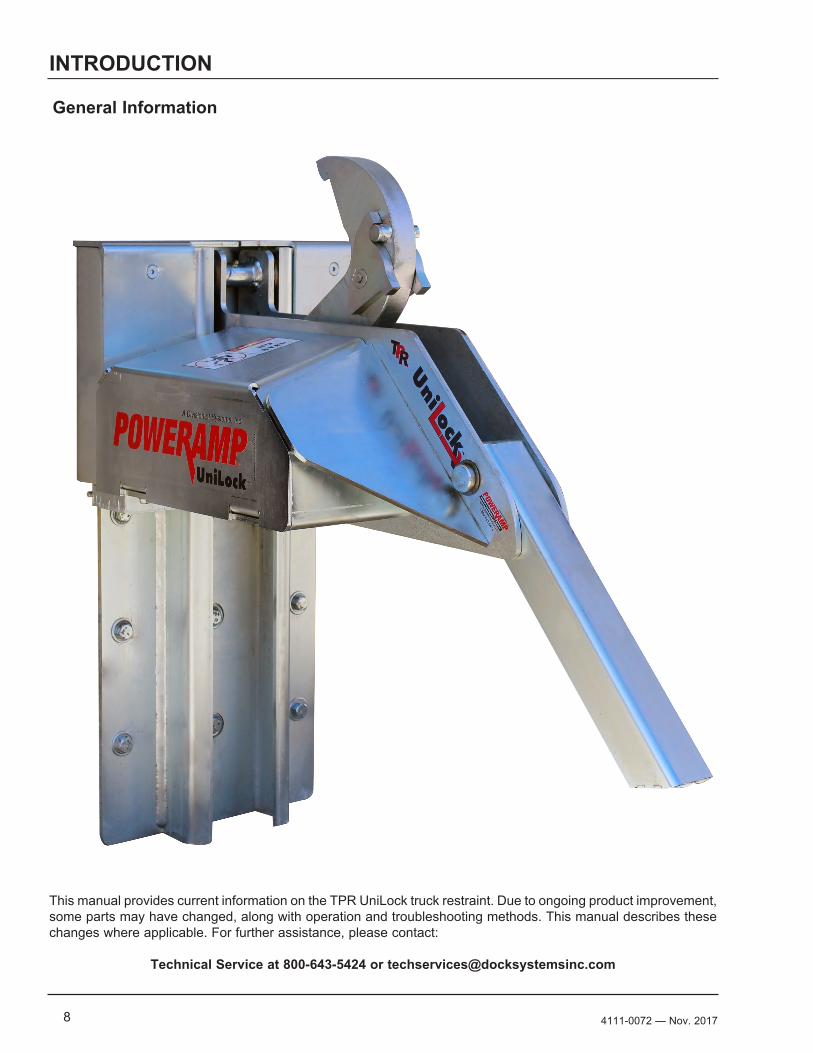
General Information
This manual provides current information on the TPR UniLock truck restraint. Due to ongoing product improvement, some parts may have changed, along with operation and troubleshooting methods. This manual describes these changes where applicable. For further assistance, please contact:
Technical Service at 800-643-5424 or [email protected]
94111-0072— Nov. 2017
INTRODUCTION
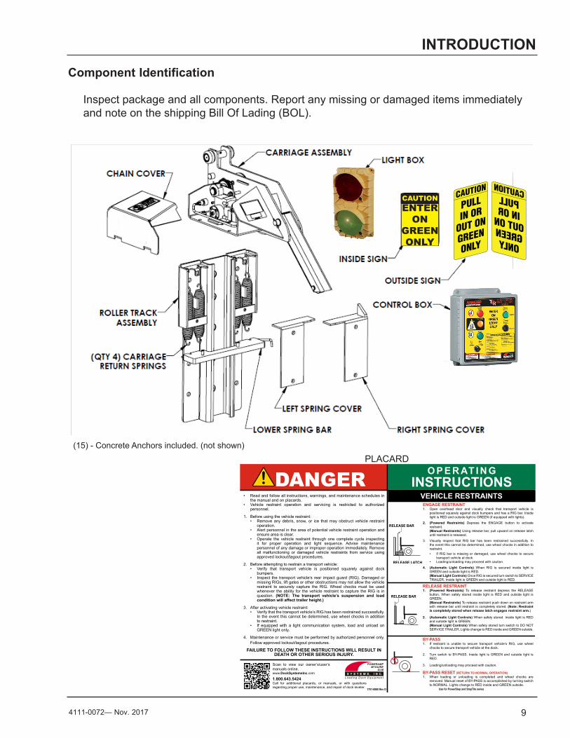
Component Identification
(15) - Concrete Anchors included. (not shown)
O P E R AT I N GINSTRUCTIONSDANGER
• Read and follow all instructions, warnings, and maintenance schedules in the manual and on placards.
• Vehicle restraint operation and servicing is restricted to authorized personnel.
1. Before using the vehicle restraint:• Remove any debris, snow, or ice that may obstruct vehicle restraint
operation.• Alert personnel in the area of potential vehicle restraint operation and
ensure area is clear.• Operate the vehicle restraint through one complete cycle inspecting
it for proper operation and light sequence. Advise maintenance personnel of any damage or improper operation immediately. Remove all malfunctioning or damaged vehicle restraints from service using approved lockout/tagout procedures.
2. Before attempting to restrain a transport vehicle:• Verify that transport vehicle is positioned squarely against dock
bumpers.• Inspect the transport vehicle’s rear impact guard (RIG). Damaged or
missing RIGs, lift gates or other obstructions may not allow the vehicle restraint to securely capture the RIG. Wheel chocks must be used whenever the ability for the vehicle restraint to capture the RIG is in question. (NOTE: The transport vehicle’s suspension and load condition will affect trailer height.)
3. After activating vehicle restraint:• Verify that the transport vehicle’s RIG has been restrained successfully.
In the event this cannot be determined, use wheel chocks in addition to restraint.
• If equipped with a light communication system, load and unload on GREEN light only.
4. Maintenance or service must be performed by authorized personnel only. Follow approved lockout/tagout procedures.
FAILURE TO FOLLOW THESE INSTRUCTIONS WILL RESULT IN DEATH OR OTHER SERIOUS INJURY.
VEHICLE RESTRAINTSENGAGE RESTRAINT1. Open overhead door and visually check that transport vehicle is
positioned squarely against dock bumpers and has a RIG bar. Inside light is RED and outside light is GREEN (if equipped with lights).
2. (Powered Restraints) Depress the ENGAGE button to activate restraint.(Manual Restraints) Using release bar, pull upward on release latch until restraint is released.
3. Visually inspect that RIG bar has been restrained successfully. In the event this cannot be determined, use wheel chocks in addition to restraint.• If RIG bar is missing or damaged, use wheel chocks to secure
transport vehicle at dock.• Loading/unloading may proceed with caution.
4. (Automatic Light Controls) When RIG is secured inside light is GREEN and outside light is RED.(Manual Light Controls) Once RIG is secured turn switch to SERVICE TRAILER. Inside light is GREEN and outside light is RED.
RELEASE RESTRAINT1. (Powered Restraints) To release restraint depress the RELEASE
button. When safely stored inside light is RED and outside light is GREEN.(Manual Restraints) To release restraint push down on restraint arm with release bar until restraint is completely stored. (Note: Restraint is completely stored when release latch engages restraint arm.)
2. (Automatic Light Controls) When safely stored inside light is RED and outside light is GREEN.(Manual Light Controls) When safely stored turn switch to DO NOT SERVICE TRAILER. Lights change to RED inside and GREEN outside.
BY-PASS1. If restraint is unable to secure transport vehicle’s RIG, use wheel
chocks to secure transport vehicle at the dock.
2. Turn switch to BY-PASS. Inside light is GREEN and outside light is RED.
3. Loading/unloading may proceed with caution.
BY-PASS RESET (RETURN TO NORMAL OPERATION)1. When loading or unloading is completed and wheel chocks are
removed. Manual reset of BY-PASS is accomplished by turning switch to NORMAL. Lights change to RED inside and GREEN outside.
Use for PowerStop and StopTite series
1.800.643.5424Call for additional placards, or manuals, or with questions regarding proper use, maintenance, and repair of dock leveler. 1751-0880 Rev D
Scan to view our owner’s/user’s manuals online.www.DockSystemsInc.com
PLACARD
Inspect package and all components. Report any missing or damaged items immediately and note on the shipping Bill Of Lading (BOL).
CAUTION
PULLIN OR
OUT ON
GREEN
ONLY
CAUTION
PULLIN OR
OUT ON
GREEN
ONLY
10 4111-0072 — Nov. 2017
INSTALLATION
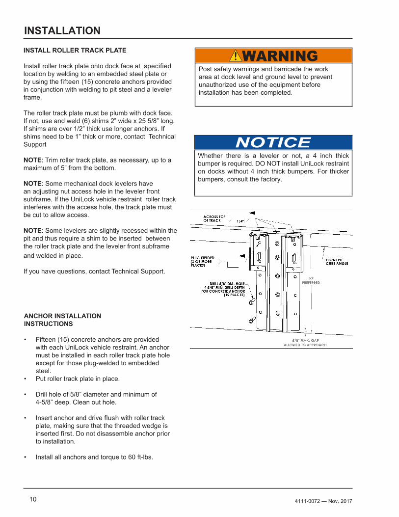
INSTALL ROLLER TRACK PLATE
Install roller track plate onto dock face at specified location by welding to an embedded steel plate or by using the fifteen (15) concrete anchors provided in conjunction with welding to pit steel and a leveler frame.
The roller track plate must be plumb with dock face. If not, use and weld (6) shims 2” wide x 25 5/8” long. If shims are over 1/2” thick use longer anchors. If shims need to be 1” thick or more, contact Technical Support
NOTE: Trim roller track plate, as necessary, up to a maximum of 5” from the bottom.
NOTE: Some mechanical dock levelers have an adjusting nut access hole in the leveler front subframe. If the UniLock vehicle restraint roller track interferes with the access hole, the track plate must be cut to allow access.
NOTE: Some levelers are slightly recessed within the pit and thus require a shim to be inserted between the roller track plate and the leveler front subframe and welded in place.
If you have questions, contact Technical Support.
ANCHOR INSTALLATION INSTRUCTIONS
• Fifteen (15) concrete anchors are provided with each UniLock vehicle restraint. An anchor must be installed in each roller track plate hole except for those plug-welded to embedded steel.
• Put roller track plate in place.
• Drill hole of 5/8” diameter and minimum of 4-5/8” deep. Clean out hole.
• Insert anchor and drive flush with roller track plate, making sure that the threaded wedge is inserted first. Do not disassemble anchor prior to installation.
• Install all anchors and torque to 60 ft-lbs.
Post safety warnings and barricade the work area at dock level and ground level to prevent unauthorized use of the equipment before installation has been completed.
Whether there is a leveler or not, a 4 inch thick bumper is required. DO NOT install UniLock restraint on docks without 4 inch thick bumpers. For thicker bumpers, consult the factory.
114111-0072— Nov. 2017
INSTALLATION
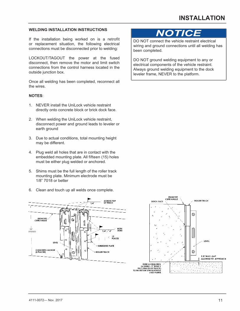
WELDING INSTALLATION INSTRUCTIONS
If the installation being worked on is a retrofit or replacement situation, the following electrical connections must be disconnected prior to welding:
LOCKOUT/TAGOUT the power at the fused disconnect, then remove the motor and limit switch connections from the control harness located in the outside junction box.
Once all welding has been completed, reconnect all the wires.
NOTES:
1. NEVER install the UniLock vehicle restraint directly onto concrete block or brick dock face.
2. When welding the UniLock vehicle restraint, disconnect power and ground leads to leveler or earth ground
3. Due to actual conditions, total mounting height may be different.
4. Plug weld all holes that are in contact with the embedded mounting plate. All fifteen (15) holes must be either plug welded or anchored.
5. Shims must be the full length of the roller track mounting plate. Minimum electrode must be 1/8” 7018 or better
6. Clean and touch up all welds once complete.
DO NOT connect the vehicle restraint electrical wiring and ground connections until all welding has been completed.
DO NOT ground welding equipment to any or electrical components of the vehicle restraint. Always ground welding equipment to the dock leveler frame, NEVER to the platform.
12 4111-0072 — Nov. 2017
INSTALLATION
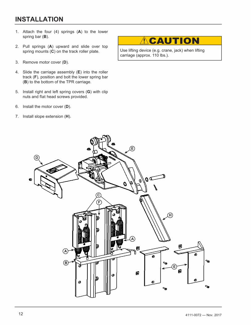
1. Attach the four (4) springs (A) to the lower spring bar (B).
2. Pull springs (A) upward and slide over top spring mounts (C) on the track roller plate.
3. Remove motor cover (D).
4. Slide the carriage assembly (E) into the roller track (F), position and bolt the lower spring bar (B) to the bottom of the TPR carriage.
5. Install right and left spring covers (G) with clip nuts and flat head screws provided.
6. Install the motor cover (D).
7. Install slope extension (H).
B
D
F
E
H
E
A
A
C
Use lifting device (e.g. crane, jack) when lifting carriage (approx. 110 lbs.).
134111-0072— Nov. 2017
INSTALLATION
Route the conduit to enter through the side or bottom of the enclosure. If the conduit could fill with water, a drip leg may be needed.
Seal the conduit in any location where the conduit crosses over temperature zones that could produce condensation.
Install spacers between the wall and enclosure to provide temperature insulation and air flow.
The UniLock vehicle restraint assembly includes a 63" long flexible wiring harness, the control box with lights and the outside signal light box. The outside junction box, conduit fittings and wire are provided by others; be sure to use a qualified installer utilizing quality materials.
Refer to component location information. Electrical schematics for wiring information can be found inside the control box.
TEMPERATURE CONTROLLED APPLICATIONINSTALLATION GUIDELINES
If the incoming electrical power for the UniLock vehicle restraint is taken from a nearby electrical appliance, e.g., overhead door opener, verify that the amperage is in accordance with local and federal codes.
The UniLock vehicle restraint 1/10 HP motor requires 120V, single phase power, 60 Hz power and 10 amps of current to operate properly.
If you have questions, contact Technical Support at (800) 643-5424.
When drilling access holes in the control box, DO NOT penetrate too deep, components may be damaged.
DO NOT turn control upside down to drill any access holes. To prevent damaged to electrical components from debris cover components prior to drilling
Seal all conduit entrances to prevent moisture from entering the control box.
DO NOT use compressed air to clean control box. Recommended to vacuum debris from inside.
The control box and all wiring should be installed by a qualified electrician in accordance with all national and local electrical codes.
Make sure that the power source has been locked out and tagged according to OSHA regulations and approved local electrical codes.
Post safety warnings and barricade the work area at dock level and ground level to prevent unauthorized use of the equipment before installation has been completed.
Where indicated, all components must be connected to a SAFETY EARTH GROUND that conforms to the 1999 National Electrical Code Section 250-50 section (a) or section (c) for a grounding electrode system.
14 4111-0072 — Nov. 2017
INSTALLATION
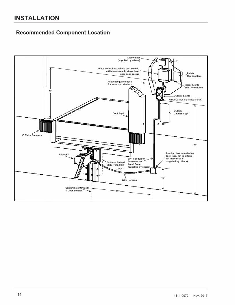
UniLock™
Centerline of UniLock& Dock Leveler 58”
15”Wire Harness
3/4” Conduit or Diameter per Local Code (supplied by others)
96”
18”
Dock Seal
48”
5”Disconnect
(supplied by others)
Place control box where best suited, within arms reach, at eye level
near door opeing
Allow adequate spacefor seals and shelters
InsideCaution Sign
Outside Lights
OutsideCaution Sign
Junction box mounted ondock face, not to extendout more than 3”(supplied by others)
4” Thick Bumpers
Optional Embed plate
Inside Lightsand Control Box
Recommended Component Location
(20x24)7953-0005
Mirror Caution Sign (Not Shown)
154111-0072— Nov. 2017
INSTALLATION
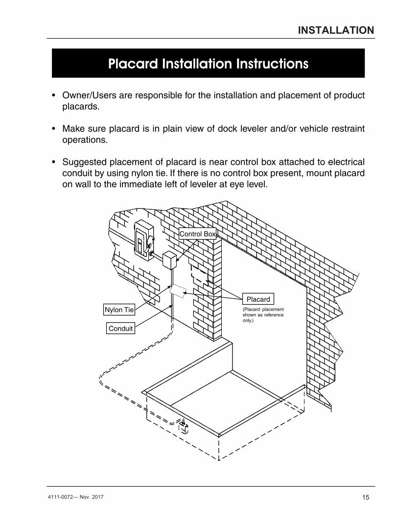
Placard Installation Instructions
Control Box
Conduit
Nylon Tie
Placard
• Owner/Users are responsible for the installation and placement of product placards.
• Make sure placard is in plain view of dock leveler and/or vehicle restraint operations.
• Suggested placement of placard is near control box attached to electrical conduit by using nylon tie. If there is no control box present, mount placard on wall to the immediate left of leveler at eye level.
(Placard placement shown as reference only.)
16 4111-0072 — Nov. 2017
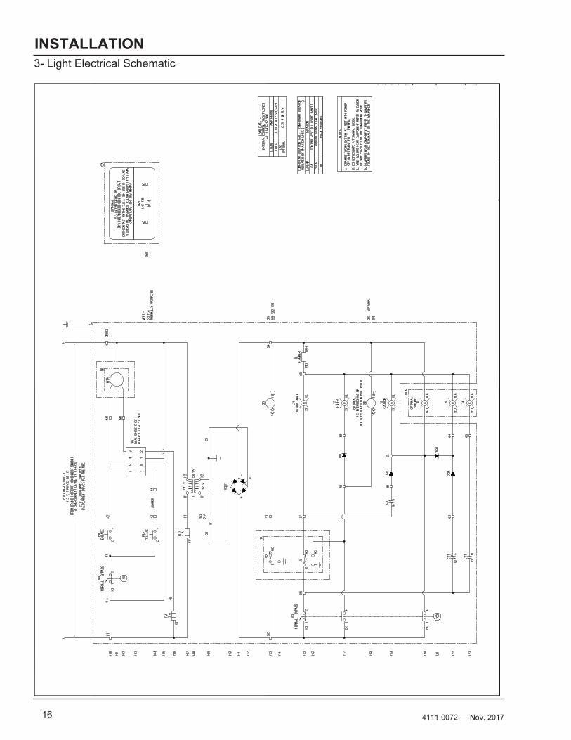
INSTALLATION3- Light Electrical Schematic
P O
W E
R A
M P
M C
G U
I R
ED
L M
S
Y
S
T
E
M
S,
I
N
C.
L o
a d
i n
g
D o
c k
E
q u
i p
m e
n t
174111-0072— Nov. 2017
INSTALLATION
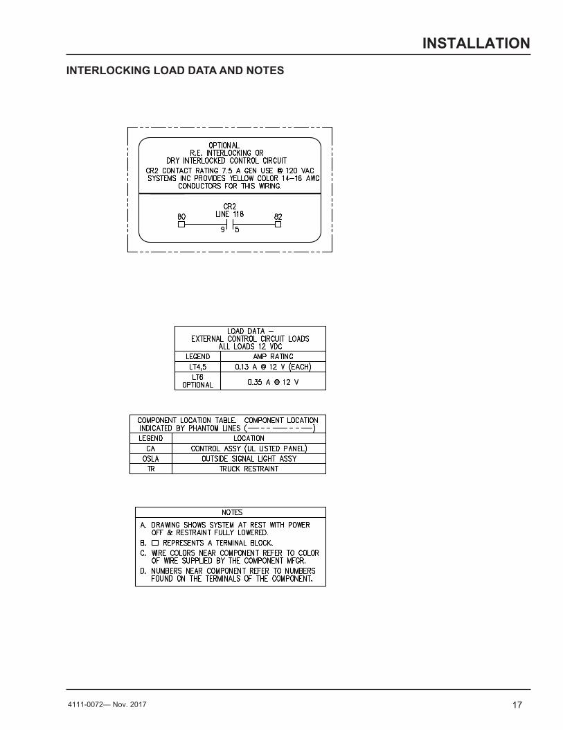
INTERLOCKING LOAD DATA AND NOTES
P O W E R A M PM C G U I R E
D L M
S Y S T E M S, I N C.L o a d i n g D o c k E q u i p m e n t
P O W E R A M PM C G U I R E
D L M
S Y S T E M S, I N C.L o a d i n g D o c k E q u i p m e n t
18 4111-0072 — Nov. 2017
OPERATION
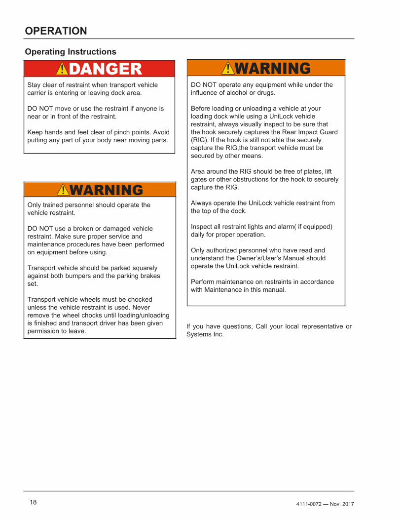
Operating Instructions
Stay clear of restraint when transport vehicle carrier is entering or leaving dock area.
DO NOT move or use the restraint if anyone is near or in front of the restraint.
Keep hands and feet clear of pinch points. Avoid putting any part of your body near moving parts.
Only trained personnel should operate the vehicle restraint.
DO NOT use a broken or damaged vehicle restraint. Make sure proper service and maintenance procedures have been performed on equipment before using.
Transport vehicle should be parked squarely against both bumpers and the parking brakes set.
Transport vehicle wheels must be chocked unless the vehicle restraint is used. Never remove the wheel chocks until loading/unloading is finished and transport driver has been given permission to leave.
DO NOT operate any equipment while under the influence of alcohol or drugs.
Before loading or unloading a vehicle at your loading dock while using a UniLock vehicle restraint, always visually inspect to be sure that the hook securely captures the Rear Impact Guard (RIG). If the hook is still not able the securely capture the RIG,the transport vehicle must be secured by other means.
Area around the RIG should be free of plates, lift gates or other obstructions for the hook to securely capture the RIG.
Always operate the UniLock vehicle restraint from the top of the dock.
Inspect all restraint lights and alarm( if equipped)daily for proper operation.
Only authorized personnel who have read and understand the Owner’s/User’s Manual should operate the UniLock vehicle restraint.
Perform maintenance on restraints in accordance with Maintenance in this manual.
If you have questions, Call your local representative or Systems Inc.
194111-0072— Nov. 2017
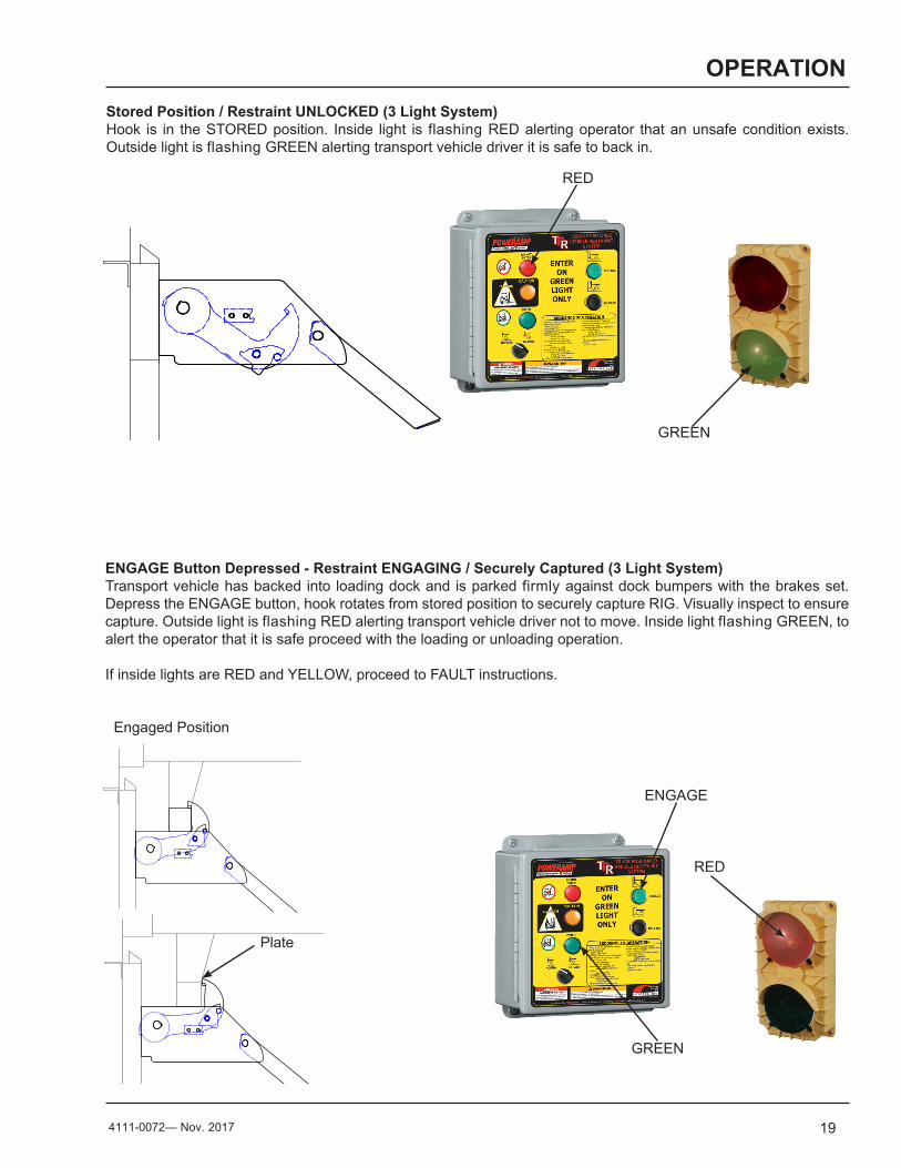
OPERATIONStored Position / Restraint UNLOCKED (3 Light System)Hook is in the STORED position. Inside light is flashing RED alerting operator that an unsafe condition exists. Outside light is flashing GREEN alerting transport vehicle driver it is safe to back in.
ENGAGE Button Depressed - Restraint ENGAGING / Securely Captured (3 Light System)Transport vehicle has backed into loading dock and is parked firmly against dock bumpers with the brakes set. Depress the ENGAGE button, hook rotates from stored position to securely capture RIG. Visually inspect to ensure capture. Outside light is flashing RED alerting transport vehicle driver not to move. Inside light flashing GREEN, to alert the operator that it is safe proceed with the loading or unloading operation.
If inside lights are RED and YELLOW, proceed to FAULT instructions.
Plate
Engaged Position
RED
GREEN
GREEN
RED
ENGAGE
20 4111-0072 — Nov. 2017
OPERATION
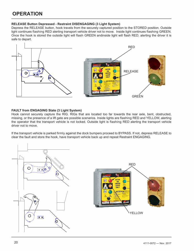
RELEASE Button Depressed - Restraint DISENGAGING (3 Light System)Depress the RELEASE button, hook travels from the securely captured position to the STORED position. Outside light continues flashing RED alerting transport vehicle driver not to move. Inside light continues flashing GREEN. Once the hook is stored the outside light will flash GREEN andinside light will flash RED, alerting the driver it is safe to depart.
FAULT from ENGAGING State (3 Light System)Hook cannot securely capture the RIG. RIGs that are located too far towards the rear axle, bent, obstructed, missing, or the presence of a lift gate are possible scenarios. Inside lights are flashing RED and YELLOW, alerting the operator that the transport vehicle is not locked. Outside light is flashing RED alerting the transport vehicle driver not to move.
If the transport vehicle is parked firmly against the dock bumpers proceed to BYPASS. If not, depress RELEASE to clear the fault and store the hook, have transport vehicle back up and repeat Restraint ENGAGING.
RED
RED
YELLOW
GREEN
RELEASE
214111-0072— Nov. 2017
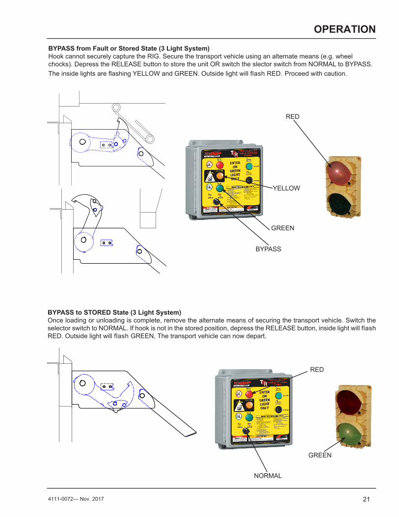
OPERATIONBYPASS from Fault or Stored State (3 Light System)Hook cannot securely capture the RIG. Secure the transport vehicle using an alternate means (e.g. wheel chocks). Depress the RELEASE button to store the unit OR switch the slector switch from NORMAL to BYPASS. The inside lights are flashing YELLOW and GREEN. Outside light will flash RED. Proceed with caution.
BYPASS to STORED State (3 Light System)Once loading or unloading is complete, remove the alternate means of securing the transport vehicle. Switch the selector switch to NORMAL. If hook is not in the stored position, depress the RELEASE button, inside light will flash RED. Outside light will flash GREEN, The transport vehicle can now depart.
RED
RED
GREEN
GREEN
YELLOW
BYPASS
NORMAL
22 4111-0072 — Nov. 2017
MAINTENANCE
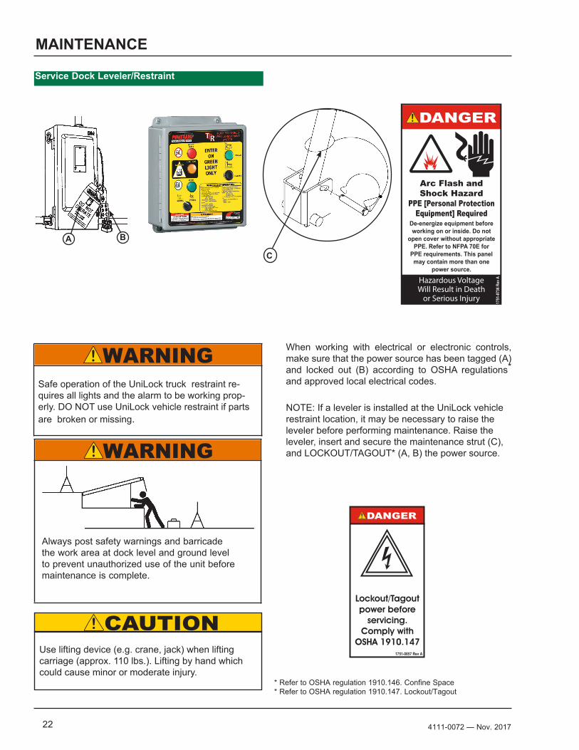
Service Dock Leveler/Restraint
When working with electrical or electronic controls, make sure that the power source has been tagged (A) and locked out (B) according to OSHA regulations* and approved local electrical codes.
NOTE: If a leveler is installed at the UniLock vehicle restraint location, it may be necessary to raise the leveler before performing maintenance. Raise the leveler, insert and secure the maintenance strut (C), and LOCKOUT/TAGOUT* (A, B) the power source.
Always post safety warnings and barricade the work area at dock level and ground level to prevent unauthorized use of the unit before maintenance is complete.
Use lifting device (e.g. crane, jack) when lifting carriage (approx. 110 lbs.). Lifting by hand which could cause minor or moderate injury.
Safe operation of the UniLock truck restraint re-quires all lights and the alarm to be working prop-erly. DO NOT use UniLock vehicle restraint if parts are broken or missing.
1.50"
3.0
0"
Decal Size: 1.5 x 3File Name: 1751-0736 Rev A
Arc Flash andShock Hazard
PPE [Personal Protection Equipment] Required
De-energize equipment before working on or inside. Do not
open cover without appropriate PPE. Refer to NFPA 70E for
PPE requirements. This panel may contain more than one
power source.
Hazardous VoltageWill Result in Death
or Serious Injury
1751
-073
6 Rev
A1.50"
3.0
0"
Control Box Size: Overlay Decal Size: 1.5 x 3File Name: 1751-0857 Rev A
Lockout/Tagout power before
servicing.Comply with
OSHA 1910.1471751-0857 Rev A
* Refer to OSHA regulation 1910.146. Confine Space* Refer to OSHA regulation 1910.147. Lockout/Tagout
C
BA
234111-0072— Nov. 2017
MAINTENANCE
Service Restraint
WEEKLY• Remove debris around UniLock vehicle restraint
and in roller track.• Verify that restraint operates through full range
of motion, engages and releases, inside/outside lights and alarm (if equipped) are working.
• Inspect motor cover and spring covers, verify good condition; replace or repair as needed
• Verify carriage assembly is able to move up and down freely with no binding or obstruction.
• Replace damaged or missing light bulbs and lenses.
• Repair, remount, or replace outside/inside signs, labels, decals and placards as required.
• Inspect dock bumpers. Four inches (4”) of protection is required. Worn, torn, loose or missing bumpers must be replaced.
• Inspect latch barrier blocks for wear or damage; replace as needed.
• Inspect latch plates and retaining ring on pivot pin for damage or wear.
• Inspect latch plates and verify they rotate without binding or obstructions. DO NOT lubricate the latch plates.
QUARTERLY• Perform all WEEKLY maintenance.• Grease rollers at fittings located on the top and
bottom axle with a synthetic oil-base moly grease with a temperature range of –40° to 170° F.
• Grease hook weldment at the fitting with a synthetic oil-base moly grease with a temperature range of –40° to 170° F.
• Inspect chain tension, 1/8-1/4 inch of play, lube chain.
• Verify brake torque is greater than 42 ft-lbs and less than 58 ft-lbs at the hook shaft, while rotating the hook from ENGAGED (45 deg) to STORED.
• Inspect the hook to shaft for free play, more than 1/4 inch tighten done the set screw to 8 ft-lbs, check again, replace as needed.
• Inspect the outside electrical connections (junction box, conduit, power harness) and outside communication light. Loose or damaged components must be repaired or replaced as needed.
• Check that all concrete anchor bolts are torqued to 60 ft-lbs.
• Inspect all welds for cracks. Repair as needed.• Remove retaining ring, remove pivot pin and
latch plates, clean off dirt debris and other foreign matter from the assembly and mating surfaces. Reinstall parts; verify parts are moving freely without binding or obstruction. DO NOT lubricate.
• Lubricate limit switch mounting bracket between drive sprocket and the cam with synthetic oil-based moly lube with a temperature range of -40 deg to 170 deg F.
• Check motor mounting bolts.• Perform operational test after all maintenance
repairs and adjustments are complete.
24 4111-0072 — Nov. 2017
ADJUSTMENTS
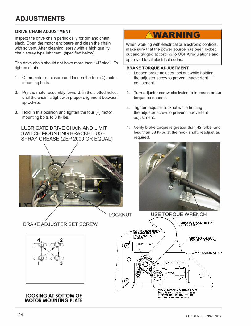
Inspect the drive chain periodically for dirt and chain slack. Open the motor enclosure and clean the chain with solvent. After cleaning, spray with a high quality chain spray type lubricant. (specified below)
The drive chain should not have more than 1/4" slack. To tighten chain:
1. Open motor enclosure and loosen the four (4) motor mounting bolts.
2. Pry the motor assembly forward, in the slotted holes, until the chain is tight with proper alignment between sprockets.
3. Hold in this position and tighten the four (4) motor mounting bolts to 8 ft- lbs.
DRIVE CHAIN ADJUSTMENT
BRAKE TORQUE ADJUSTMENT1. Loosen brake adjuster locknut while holding
the adjuster screw to prevent inadvertent adjustment.
2. Turn adjuster screw clockwise to increase brake torque as needed.
3. Tighten adjuster locknut while holding the adjuster screw to prevent inadvertent adjustment.
4. Verify brake torque is greater than 42 ft-lbs and less than 58 ft-lbs at the hook shaft, readjust as required.
When working with electrical or electronic controls, make sure that the power source has been locked out and tagged according to OSHA regulations and approved local electrical codes.
LOCKNUT
BRAKE ADJUSTER SET SCREW
USE TORQUE WRENCH
LUBRICATE DRIVE CHAIN AND LIMIT SWITCH MOUNTING BRACKET. USE SPRAY GREASE (ZEP 2000 OR EQUAL)
LEFT
96 IN-LB
254111-0072— Nov. 2017
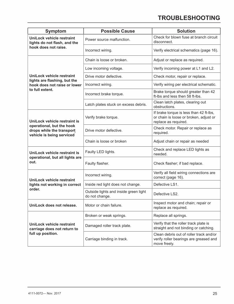
TROUBLESHOOTING
Symptom Possible Cause SolutionUniLock vehicle restraint lights do not flash, and the hook does not raise.
Power source malfunction. Check for blown fuse at branch circuit disconnect.
Incorrect wiring. Verify electrical schematics (page 16).
UniLock vehicle restraint lights are flashing, but the hook does not raise or lower to full extent.
Chain is loose or broken. Adjust or replace as required.
Low incoming voltage. Verify incoming power at L1 and L2.
Drive motor defective. Check motor, repair or replace.
Incorrect wiring. Verify wiring per electrical schematic.
Incorrect brake torque. Brake torque should greater than 42 ft-lbs and less then 58 ft-lbs.
Latch plates stuck on excess debris. Clean latch plates, clearing out obstructions.
UniLock vehicle restraint is operational, but the hook drops while the transport vehicle is being serviced
.
Verify brake torque.If brake torque is less than 42 ft-lbs, or chain is loose or broken, adjust or replace as required.
Drive motor defective. Check motor. Repair or replace as required.
Chain is loose or broken Adjust chain or repair as needed
UniLock vehicle restraint is operational, but all lights are out.
Faulty LED lights. Check and replace LED lights as needed.
Faulty flasher. Check flasher; if bad replace.
UniLock vehicle restraint lights not working in correct order.
Incorrect wiring. Verify all field wiring connections are correct (page 16).
Inside red light does not change. Defective LS1.
Outside lights and inside green light do not change. Defective LS2.
UniLock does not release. Motor or chain failure. Inspect motor and chain; repair or replace as required.
UniLock vehicle restraint carriage does not return to full up position.
Broken or weak springs. Replace all springs.
Damaged roller track plate. Verify that the roller track plate is straight and not binding or catching.
Carriage binding in track.Clean debris out of roller track and/or verify roller bearings are greased and move freely.
26 4111-0072 — Nov. 2017
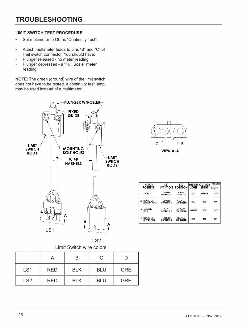
TROUBLESHOOTING
• Set multimeter to Ohms “Continuity Test”.
• Attach multimeter leads to pins “B” and “C” of limit switch connector. You should have:
• Plunger released - no meter reading • Plunger depressed - a “Full Scale” meter
reading
NOTE: The green (ground) wire of the limit switch does not have to be tested. A continuity test lamp may be used instead of a multimeter.
LIMIT SWITCH TEST PROCEDURE
A B C D
LS1 RED BLK BLU GRE
LS2 RED BLK BLU GRE
Limit Switch wire colors
LS1
LS2
Yellow Light
274111-0072— Nov. 2017
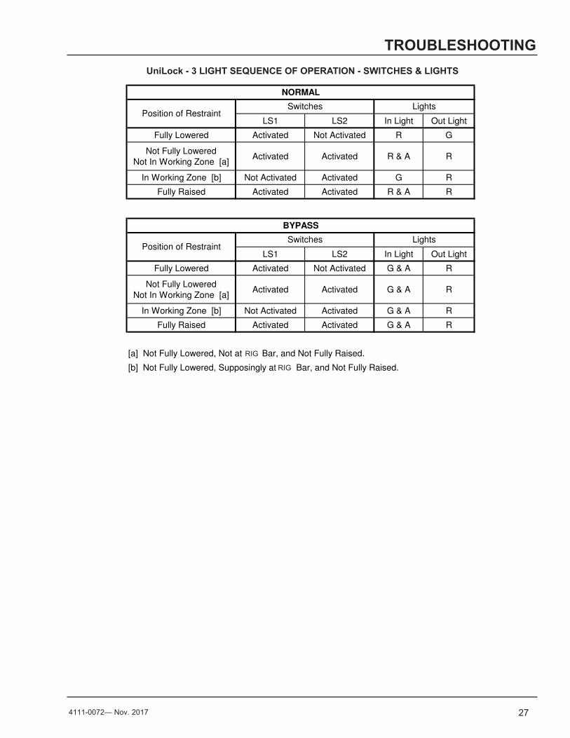
LS1 LS2 In Light Out Light
Fully Lowered Activated Not Activated R G
Not Fully Lowered
Not In Working Zone [a]Activated Activated R & A R
In Working Zone [b] Not Activated Activated G R
Fully Raised Activated Activated R & A R
LS1 LS2 In Light Out Light
Fully Lowered Activated Not Activated G & A R
Not Fully Lowered
Not In Working Zone [a]Activated Activated G & A R
In Working Zone [b] Not Activated Activated G & A R
Fully Raised Activated Activated G & A R
[a] Not Fully Lowered, Not at ICC Bar, and Not Fully Raised.
[b] Not Fully Lowered, Supposingly at ICC Bar, and Not Fully Raised.
NORMAL
BYPASS
Switches
Switches
TPR 3-LIGHT SEQUENCE OF OPERATION - SWITCHES & LIGHTS
Lights
Lights
Position of Restraint
Position of Restraint
TROUBLESHOOTINGUniLock - 3 LIGHT SEQUENCE OF OPERATION - SWITCHES & LIGHTS
RIG
RIG
28 4111-0072 — Nov. 2017
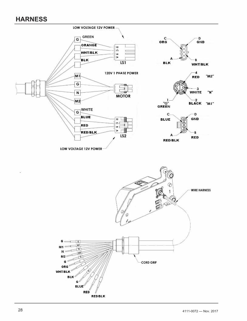
HARNESS
GREEN
WHITE
294111-0072— Nov. 2017
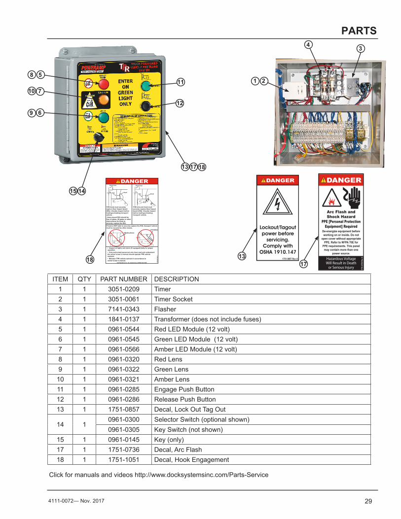
ITEM QTY PART NUMBER DESCRIPTION1 1 3051-0209 Timer2 1 3051-0061 Timer Socket3 1 7141-0343 Flasher4 1 1841-0137 Transformer (does not include fuses)5 1 0961-0544 Red LED Module (12 volt)6 1 0961-0545 Green LED Module (12 volt)7 1 0961-0566 Amber LED Module (12 volt) 8 1 0961-0320 Red Lens9 1 0961-0322 Green Lens
10 1 0961-0321 Amber Lens 11 1 0961-0285 Engage Push Button12 1 0961-0286 Release Push Button13 1 1751-0857 Decal, Lock Out Tag Out
14 10961-0300 Selector Switch (optional shown)0961-0305 Key Switch (not shown)
15 1 0961-0145 Key (only)17 1 1751-0736 Decal, Arc Flash18 1 1751-1051 Decal, Hook Engagement
PARTS
Click for manuals and videos http://www.docksystemsinc.com/Parts-Service
1.50"
3.0
0"
Decal Size: 1.5 x 3File Name: 1751-0736 Rev A
Arc Flash andShock Hazard
PPE [Personal Protection Equipment] Required
De-energize equipment before working on or inside. Do not
open cover without appropriate PPE. Refer to NFPA 70E for
PPE requirements. This panel may contain more than one
power source.
Hazardous VoltageWill Result in Death
or Serious Injury
1751
-073
6 Re
v A
1.50"
3.0
0"
Control Box Size: Overlay Decal Size: 1.5 x 3File Name: 1751-0857 Rev A
Lockout/Tagout power before
servicing.Comply with
OSHA 1910.1471751-0857 Rev A
Control Box Size: Overlay Decal Size: 4 x 6.5File Name: 1751-1051 Rev A
Call Systems Inc. for assistance at (800) 643-5424 1751
-105
1 Rev
A
• Inspect all lights and alarm (if equipped) daily for proper operation.• Only authorized personnel who have read and understand the owner’s/user’s manual should operate TPR vehicle restraint.• Maintain TPR vehicle restraint in accordance to owner’s/user’s manual.
Dock Face
HookRIG
Obstructions
If hook is NOT able to securely capture the RIG, transport vehicle must be secured by other means.
TPR Hook must securely capture Rear Impact Guard (RIG). Visually inspect before loading/unloading transport vehicle.• Area around RIG should be free of plates, lift gates or other obstructions for hook to securely capture the RIG.
TPR UniLock Hook must securely capture Rear Impact Guard (RIG). Visually inspect before loading/unloading transport vehicle.
Dock Face
RIG Hook
Lift Gates
8 5
9
7
6
1011
12
4
1415
21
3
17
13 17 18
1318
30 4111-0072 — Nov. 2017
PARTS
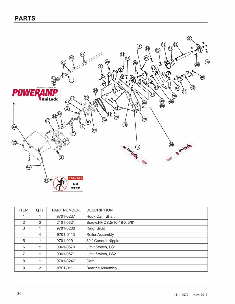
ITEM QTY PART NUMBER DESCRIPTION1 1 9701-0237 Hook Cam Shaft 2 3 2101-0321 Screw,HHCS,5/16-18 X 5/8” 3 1 9701-0200 Ring, Snap4 4 9701-0113 Roller Assembly5 1 9701-0201 3/4” Conduit Nipple6 1 0961-0570 Limit Switch, LS1
7 1 0961-0571 Limit Switch, LS2
8 1 9701-0247 Cam
9 2 9701-0111 Bearing Assembly
OPTIONAL MOTOR/CHAIN COVER
TOLERANCES(UNLESS OTHERWISE NOTED)
FRACTIONAL: 1/32"DECIMAL: .00 = .01"
.000 = .005"
ANGULAR: 1
MATERIAL
DRAWN BY CHECKED BY
DRAWING NO.
DATEBDK 11/16/2016CarriageAssembly -DYN HOOK
FOR MANUALPAGE 34.idw
P O W E R A M PM C G U I R E
D L M
S Y S T E M S, I N C.L o a d i n g D o c k E q u i p m e n t
This print is the property of Systems, Inc. and represents a proprietary article in which Systems, Inc. retains any and all patent and other rights, including exclusive rights of use and/or manufacture and/or sale. Possession of this print does not convey any permission to reproduce, print or manufacture the article or articles shown therein, such permission to be granted only by written authorization signed by an officer or other authorized agent of Systems, Inc. thereof.
STOCK NO.
Decal Size:11 x 3.5File Name: 1751-1101Black and Red on Clear
™ www.
Powe
rmap
.com
800
.643.5
424
39
33
37 36
2
12
16
9
2022
28
29
26
42
34
31
48
3835
1414
26
17
47
23
5
2730
File Name: 1751-0149 REV BDecal Size: 5 x 2.5
NO STEP
1751-0149 Rev B
19
4
3
1318
11 6
15
7
8
24
2149
32
39
43
21
1
46
49
4445
40
Decal 1751-1102Outside Black lines are not printed - shows edge of decalCircle needs to be die cut - black line not printed
www.poweramp.com
1.800.643.5424
™
Decal 1751-1103 Outside Black lines are not printed - shows edge of decalCircle needs to be die cut - black line not printed
www.poweramp.com
1.800.643.5424
™
41
50
41
314111-0072— Nov. 2017
PARTS
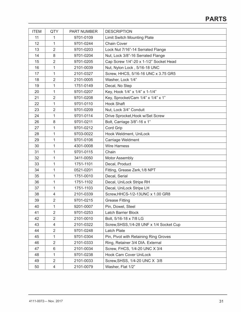
ITEM QTY PART NUMBER DESCRIPTION11 1 9701-0109 Limit Switch Mounting Plate12 1 9701-0244 Chain Cover13 2 9701-0203 Lock Nut 7/16”-14 Serrated Flange14 8 9701-0204 Nut, Lock 3/8”-16 Serrated Flange15 2 9701-0205 Cap Screw 1/4”-20 x 1-1/2” Socket Head16 1 2101-0039 Nut, Nylon Lock , 5/16-18 UNC17 1 2101-0327 Screw, HHCS, 5/16-16 UNC x 3.75 GR518 2 2101-0005 Washer, Lock 1/4”19 1 1751-0149 Decal, No Step20 1 9701-0207 Key, Hook 1/4” x 1/4” x 1-1/4”21 2 9701-0208 Key, Sprocket/Cam 1/4” x 1/4” x 1”22 1 9701-0110 Hook Shaft23 2 9701-0209 Nut, Lock 3/4” Conduit24 1 9701-0114 Drive Sprocket,Hook w/Set Screw26 8 9701-0211 Bolt, Carriage 3/8”-16 x 1”27 1 9701-0212 Cord Grip28 1 9703-0022 Hook Weldment, UniLock29 1 9701-0106 Carriage Weldment30 1 4301-0008 Wire Harness31 1 9701-0115 Chain32 1 3411-0050 Motor Assembly33 1 1751-1101 Decal, Product34 1 0521-0201 Fitting, Grease Zerk,1/8 NPT35 1 1751-0010 Decal, Serial36 1 1751-1102 Decal, UniLock Stripe RH37 1 1751-1103 Decal, UniLock Stripe LH38 4 2101-0339 Screw,HHCS-1/2-13UNC x 1.00 GR839 2 9701-0215 Grease Fitting40 1 9201-0007 Pin, Dowel, Steel41 2 9701-0253 Latch Barrier Block42 2 2101-0010 Bolt, 5/16-18 x 7/8 LG43 4 2101-0322 Screw,SHSS,1/4-28 UNF x 1/4 Socket Cup44 2 9701-0248 Latch Plate45 1 9701-0304 Pin, Pivot with Retaining Ring Groves46 2 2101-0333 Ring, Retainer 3/4 DIA. External47 6 2101-0034 Screw, FHCS, 1/4-20 UNC X 3/448 1 9701-0238 Hook Cam Cover UniLock49 2 2101-0033 Screw,SHSS, 1/4-20 UNC X 3/850 4 2101-0079 Washer, Flat 1/2”
32 4111-0072 — Nov. 2017
PARTS
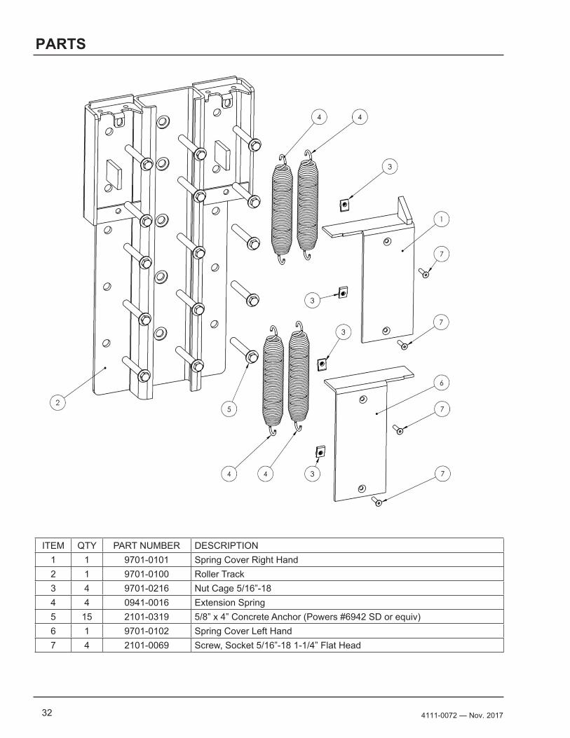
ITEM QTY PART NUMBER DESCRIPTION1 1 9701-0101 Spring Cover Right Hand2 1 9701-0100 Roller Track3 4 9701-0216 Nut Cage 5/16”-184 4 0941-0016 Extension Spring5 15 2101-0319 5/8” x 4” Concrete Anchor (Powers #6942 SD or equiv)6 1 9701-0102 Spring Cover Left Hand7 4 2101-0069 Screw, Socket 5/16”-18 1-1/4” Flat Head
334111-0072— Nov. 2017
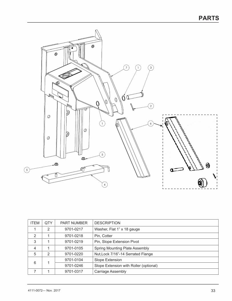
ITEM QTY PART NUMBER DESCRIPTION1 2 9701-0217 Washer, Flat 1” x 18 gauge
2 1 9701-0218 Pin, Cotter3 1 9701-0219 Pin, Slope Extension Pivot
4 1 9701-0105 Spring Mounting Plate Assembly5 2 9701-0220 Nut,Lock 7/16”-14 Serrated Flange
6 19701-0104 Slope Extension9701-0246 Slope Extension with Roller (optional)
7 1 9701-0317 Carriage Assembly
PARTS
34 4111-0072 — Nov. 2017
PARTS
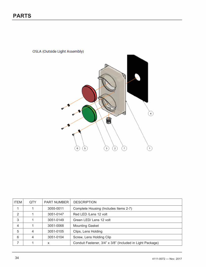
ITEM QTY PART NUMBER DESCRIPTION
1 1 3055-0011 Complete Housing (Includes Items 2-7)
2 1 3051-0147 Red LED /Lens 12 volt
3 1 3051-0149 Green LED/ Lens 12 volt
4 1 3051-0068 Mounting Gasket
5 4 3051-0105 Clips, Lens Holding
6 4 3051-0104 Screw, Lens Holding Clip
7 1 x Conduit Fastener, 3/4” x 3/8” (Included in Light Package)
354111-0072— Nov. 2017
PLACARD
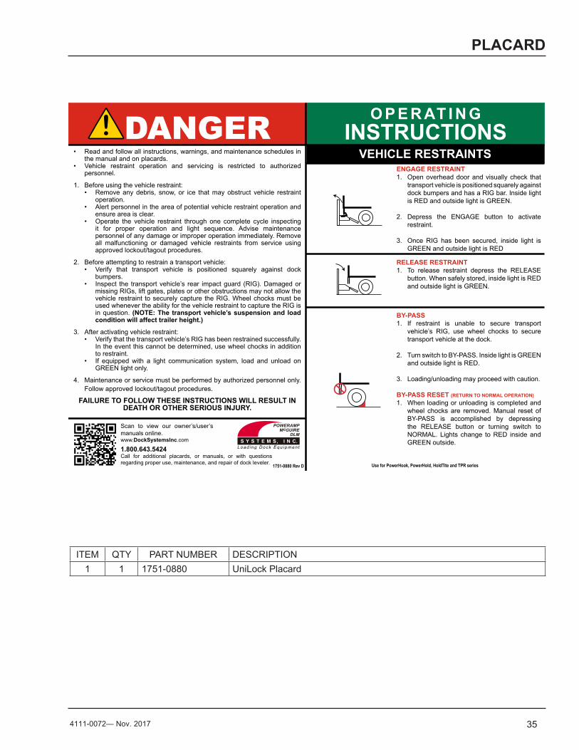
ITEM QTY PART NUMBER DESCRIPTION1 1 1751-0880 UniLock Placard
O P E R AT I N GINSTRUCTIONSDANGER
• Read and follow all instructions, warnings, and maintenance schedules in the manual and on placards.
• Vehicle restraint operation and servicing is restricted to authorized personnel.
1. Before using the vehicle restraint:• Remove any debris, snow, or ice that may obstruct vehicle restraint
operation.• Alert personnel in the area of potential vehicle restraint operation and
ensure area is clear.• Operate the vehicle restraint through one complete cycle inspecting
it for proper operation and light sequence. Advise maintenance personnel of any damage or improper operation immediately. Remove all malfunctioning or damaged vehicle restraints from service using approved lockout/tagout procedures.
2. Before attempting to restrain a transport vehicle:• Verify that transport vehicle is positioned squarely against dock
bumpers.• Inspect the transport vehicle’s rear impact guard (RIG). Damaged or
missing RIGs, lift gates, plates or other obstructions may not allow the vehicle restraint to securely capture the RIG. Wheel chocks must be used whenever the ability for the vehicle restraint to capture the RIG is in question. (NOTE: The transport vehicle’s suspension and load condition will affect trailer height.)
3. After activating vehicle restraint:• Verify that the transport vehicle’s RIG has been restrained successfully.
In the event this cannot be determined, use wheel chocks in addition to restraint.
• If equipped with a light communication system, load and unload on GREEN light only.
4. Maintenance or service must be performed by authorized personnel only. Follow approved lockout/tagout procedures.
FAILURE TO FOLLOW THESE INSTRUCTIONS WILL RESULT IN DEATH OR OTHER SERIOUS INJURY.
VEHICLE RESTRAINTSENGAGE RESTRAINT1. Open overhead door and visually check that
transport vehicle is positioned squarely against dock bumpers and has a RIG bar. Inside light is RED and outside light is GREEN.
2. Depress the ENGAGE button to activate restraint.
3. Once RIG has been secured, inside light is GREEN and outside light is RED
RELEASE RESTRAINT1. To release restraint depress the RELEASE
button. When safely stored, inside light is RED and outside light is GREEN.
BY-PASS1. If restraint is unable to secure transport
vehicle’s RIG, use wheel chocks to secure transport vehicle at the dock.
2. Turn switch to BY-PASS. Inside light is GREEN and outside light is RED.
3. Loading/unloading may proceed with caution.
BY-PASS RESET (RETURN TO NORMAL OPERATION)1. When loading or unloading is completed and
wheel chocks are removed. Manual reset of BY-PASS is accomplished by depressing the RELEASE button or turning switch to NORMAL. Lights change to RED inside and GREEN outside.
Use for PowerHook, PowerHold, HoldTite and TPR series
1.800.643.5424Call for additional placards, or manuals, or with questions regarding proper use, maintenance, and repair of dock leveler. 1751-0880 Rev D
Scan to view our owner’s/user’s manuals online.www.DockSystemsInc.com
36 4111-0072 — Nov. 2017
PARTS
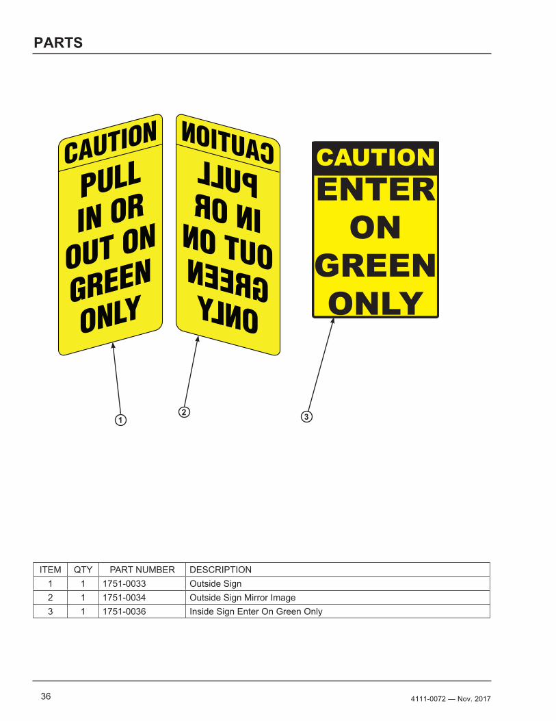
ITEM QTY PART NUMBER DESCRIPTION1 1 1751-0033 Outside Sign 2 1 1751-0034 Outside Sign Mirror Image3 1 1751-0036 Inside Sign Enter On Green Only
CAUTION
PULLIN OR
OUT ON
GREEN
ONLY
CAUTION
PULLIN OR
OUT ON
GREEN
ONLY
1 2 3
374111-0072— Nov. 2017
MISCELLANEOUS
Customer Information
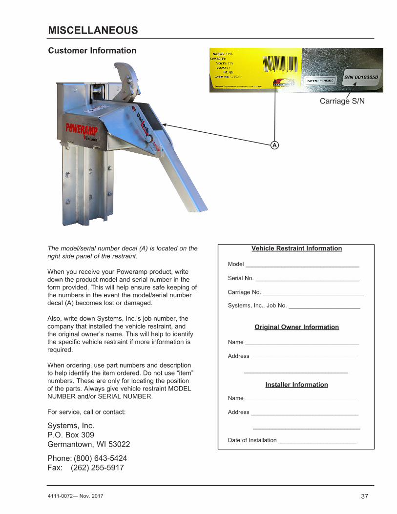
The model/serial number decal (A) is located on the right side panel of the restraint.
When you receive your Poweramp product, write down the product model and serial number in the form provided. This will help ensure safe keeping of the numbers in the event the model/serial number decal (A) becomes lost or damaged.
Also, write down Systems, Inc.’s job number, the company that installed the vehicle restraint, and the original owner’s name. This will help to identify the specific vehicle restraint if more information is required.
When ordering, use part numbers and description to help identify the item ordered. Do not use “item” numbers. These are only for locating the position of the parts. Always give vehicle restraint MODEL NUMBER and/or SERIAL NUMBER.
For service, call or contact:
Systems, Inc.P.O. Box 309Germantown, WI 53022
Phone: (800) 643-5424Fax: (262) 255-5917
Vehicle Restraint Information
Model ___________________________________
Serial No. ________________________________
Carriage No. _______________________________
Systems, Inc., Job No. ______________________
Original Owner Information
Name ___________________________________
Address _________________________________
________________________________
Installer Information
Name ___________________________________
Address _________________________________
_________________________________
Date of Installation ________________________
Carriage S/N
A
STANDARD PRODUCT WARRANTY
SYSTEMS, INC. warrants that its products will be free from defects in design, materials and workmanship for a period of one (1) year from the date of shipment. All claims for breach of this warranty must be made within 30 days after the defect is or can with reasonable care, be detected. In no event shall any claim be made more than 30 days after this warranty has expired. In order to be entitled to the benefits of this warranty, the product must have been properly installed, maintained and operated in accordance with all manufacturer’s recommendations and/or specified design parameters and not otherwise have been subject to abuse, misuse, misapplication, acts of nature, overloading, unauthorized repair or modification, application in a corrosive environment or lack of maintenance. Periodic lubrication, adjustment and inspection in accordance with all manufacturers’ recommendations are the sole responsibility of the Owner/User.
In the event of a defect, as determined by SYSTEMS INC., covered by this warranty, SYSTEMS INC. shall remedy such defect by repairing or replacing any defective equipment or parts, bearing the cost for the parts, labor and transportation. This shall be exclusive remedy for all claims whether based on contract, negligence or strict liability.
WARRANTY LIMITATIONS
THE ABOVE WARRANTIES ARE IN LIEU OF ANY OTHER WARRANTIES, WHETHER EXPRESSED OR IMPLIED, INCLUDING BUT NOT LIMITED TO ANY IMPLIED WARRANTY OF MERCHANTABILITY OR FITNESS FOR A PARTICULAR PURPOSE. SYSTEMS INC. AND ITS SUBSIDIARIES SHALL NOT IN ANY EVENT BE LIABLE TO ANYONE, INCLUDING THIRD PARTIES, FOR INCIDENTAL, CONSEQUENTIAL OR SPECIAL DAMAGES OF ANY KIND INCLUDING BUT NOT LIMITED TO, BREACH OF WARRANTY, LOSS OF USE, LOSS OF PROFIT, INTERRUPTION OF BUSINESS OR LOSS OF GOODWILL.