Embed Size (px)
Citation preview

706 100 183 (TPX 502-1 GB Version 0.0) 23.10.2003
Pad printing machine
TPX 502
GB ____ Operating instruction


Danger Warning for Machine Operation
Standard Tampon There is no risk of injury for the fingers while using standard tampons (tampon strength ≥ 35 to 40 mm) if used as intended. While using special tampons, tampon assembly, etc. additional protective measures must be carried out if required; i.e. two-hand switch, light barrier, loading and unload-ing equipment. Printing matter intake Printing Matter According to the kind / shape of the printing matter / printing matter intake, the risk of injury (jamming risk) between the printing matter / printing matter intake and the ex-tending sword of the tampon cleaning changes. Additional protective measures must be carried out if required; i.e. two-hand switch, light barrier, loading and unloading equipment.
Before casing sheets are taken off, the machine must be shut off and detached from the electricity network!
Settings, color and thinner adiition, as well as any working in the tampon free space may only be carried out when the machine is at rest.
Hazardous Materials (Colors, Lacquers, Solvents, Leveling Agents, etc.) While handling hazardous materials to be used(colors, detergents, additives), the information of each respective safety data sheets must be paid attention to.

3 23.10.2003 TPX 502-1 GB
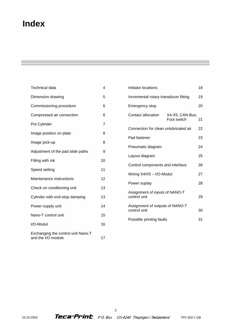
Technical data 4
Dimension drawing 5
Commissioning procedure 6
Compressed air connection 6
Pot Cylinder 7
Image position on plate 8
Image pick-up 8
Adjustment of the pad slide paths 9
Filling with ink 10
Speed setting 11
Maintenance instructions 12
Check on conditioning unit 13
Cylinder with end-stop damping 13
Power supply unit 14
Nano-T control unit 15
I/O-Modul 16
Exchanging the control unit Nano-T and the I/O module 17
Initiator locations 18
Incremental rotary transducer fitting 19
Emergency stop 20
Contact allocation X4-X5, CAN-Bus, Foot switch 21
Connection for clean unlubricated air 22
Pad fastener 23
Pneumatic diagram 24
Layout diagram 25
Control components and interface 26
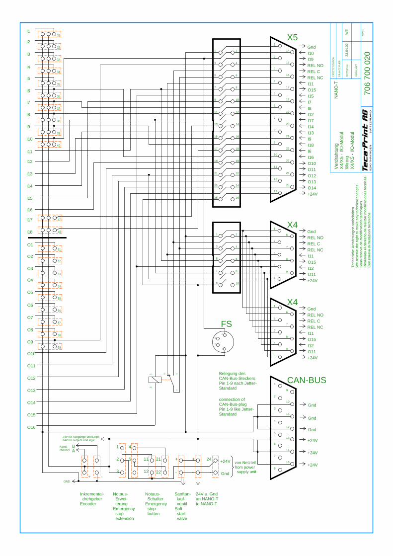
Wiring X4/X5 – I/O-Modul 27
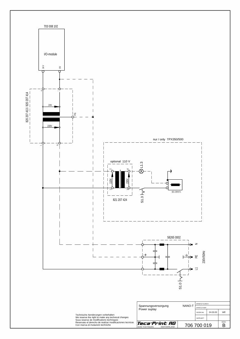
Power suplay 28
Assignment of inputs of NANO-T control unit 29
Assignment of outputs of NANO-T control unit 30
Possible printing faults 31
Index
4 TPX 502-1 GB 23.10.2003
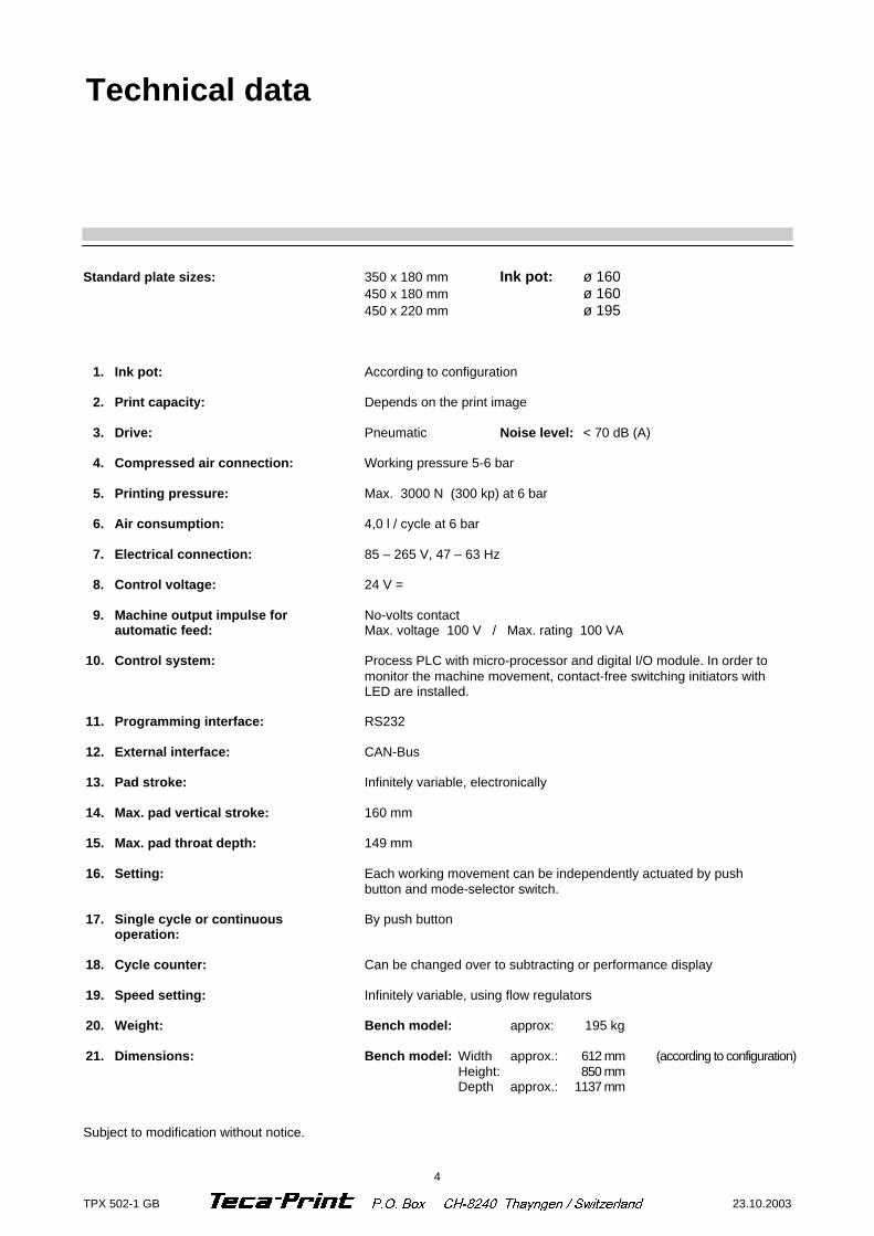
Standard plate sizes: 350 x 180 mm Ink pot: ø 160 450 x 180 mm ø 160 450 x 220 mm ø 195 1. Ink pot: According to configuration 2. Print capacity: Depends on the print image 3. Drive: Pneumatic Noise level: < 70 dB (A) 4. Compressed air connection: Working pressure 5-6 bar 5. Printing pressure: Max. 3000 N (300 kp) at 6 bar 6. Air consumption: 4,0 l / cycle at 6 bar 7. Electrical connection: 85 – 265 V, 47 – 63 Hz 8. Control voltage: 24 V = 9. Machine output impulse for No-volts contact automatic feed: Max. voltage 100 V / Max. rating 100 VA 10. Control system: Process PLC with micro-processor and digital I/O module. In order to
monitor the machine movement, contact-free switching initiators with LED are installed.
11. Programming interface: RS232 12. External interface: CAN-Bus 13. Pad stroke: Infinitely variable, electronically
14. Max. pad vertical stroke: 160 mm 15. Max. pad throat depth: 149 mm 16. Setting: Each working movement can be independently actuated by push
button and mode-selector switch. 17. Single cycle or continuous By push button operation: 18. Cycle counter: Can be changed over to subtracting or performance display 19. Speed setting: Infinitely variable, using flow regulators 20. Weight: Bench model: approx: 195 kg 21. Dimensions: Bench model: Width approx.: 612 mm (according to configuration) Height: 850 mm Depth approx.: 1137 mm Subject to modification without notice.
Technical data
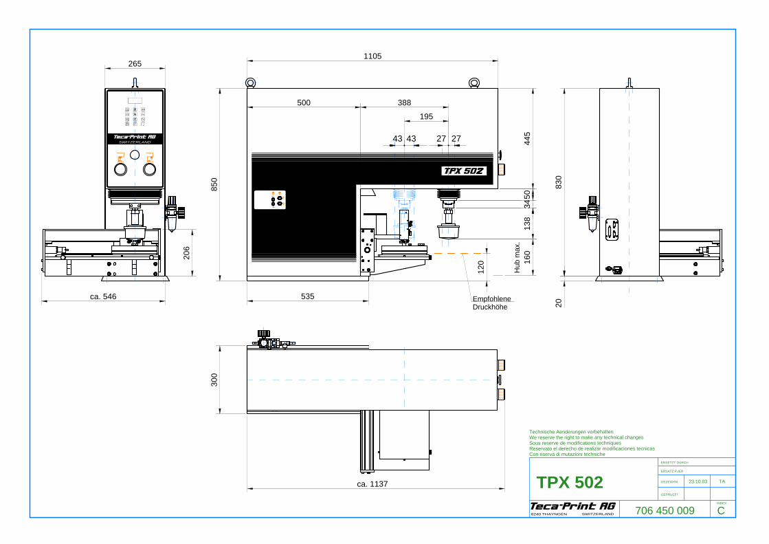
27 27
Hub
max
.
4343
1105
500 388
195
535
300
ca. 1137
850
120 16
013
834
5044
5
2083
0
706 450 009
23.10.03 TATPX 502ERSETZT DURCH
ERSATZ FUER
GEZEICHN.
GEPRUEFT
INDEX
8240 THAYNGEN SWITZERLAND
Technische Aenderungen vorbehaltenWe reserve the right to make any technical changesSous reserve de modifications techniquesReservato el derecho de realizar modificaciones tecnicasCon riserva di mutazioni techniche
265
EmpfohleneDruckhöhe
206
ca. 546
SWITZERLAND
C
6 TPX 502-1 GB 23.10.2003
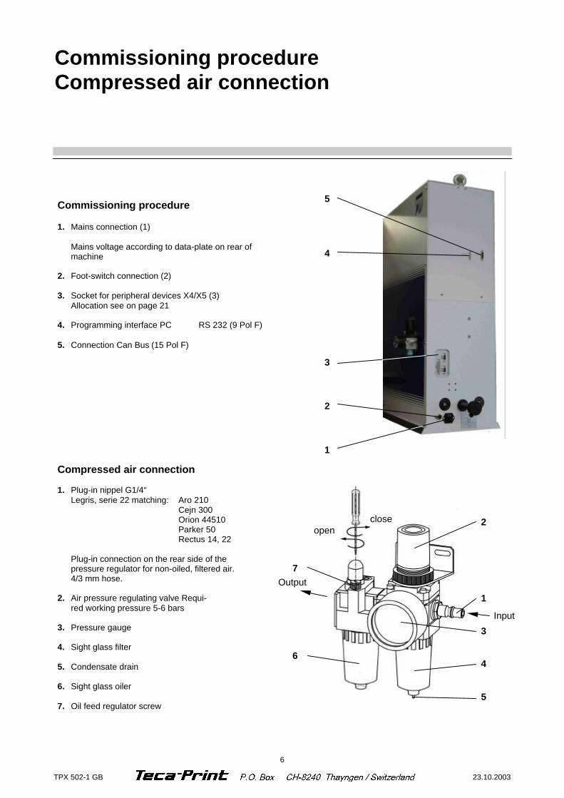
Commissioning procedure Compressed air connection
Commissioning procedure 1. Mains connection (1) Mains voltage according to data-plate on rear of
machine 2. Foot-switch connection (2) 3. Socket for peripheral devices X4/X5 (3) Allocation see on page 21 4. Programming interface PC RS 232 (9 Pol F) 5. Connection Can Bus (15 Pol F)
Compressed air connection 1. Plug-in nippel G1/4“ Legris, serie 22 matching: Aro 210 Cejn 300 Orion 44510 Parker 50 Rectus 14, 22 Plug-in connection on the rear side of the
pressure regulator for non-oiled, filtered air. 4/3 mm hose.
2. Air pressure regulating valve Requi- red working pressure 5-6 bars 3. Pressure gauge 4. Sight glass filter 5. Condensate drain 6. Sight glass oiler 7. Oil feed regulator screw
7 6
2 1 3 4 5
5 4 3 2 1
close open
Output
Input
7 23.10.2003 TPX 502-1 GB
4
5
7
6
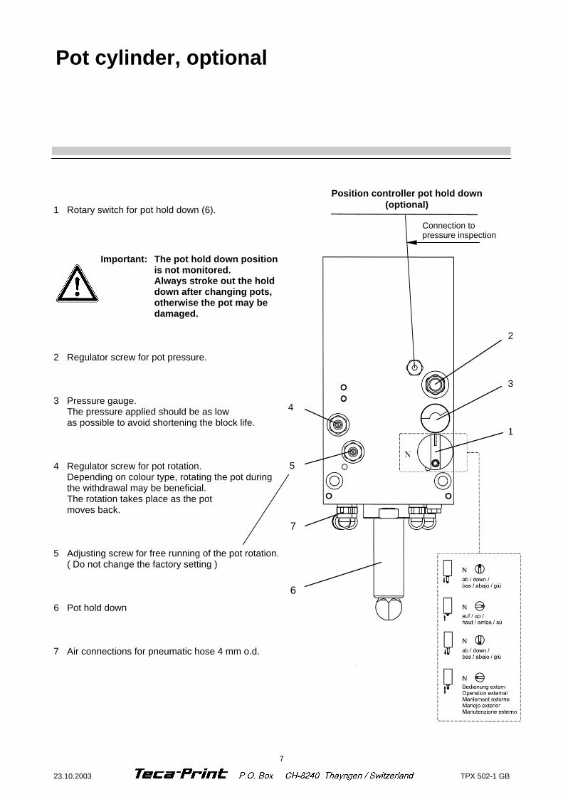
Pot cylinder, optional
1 Rotary switch for pot hold down (6).
Important: The pot hold down position is not monitored. Always stroke out the hold down after changing pots, otherwise the pot may be damaged.
2 Regulator screw for pot pressure. 3 Pressure gauge. The pressure applied should be as low as possible to avoid shortening the block life. 4 Regulator screw for pot rotation. Depending on colour type, rotating the pot during the withdrawal may be beneficial. The rotation takes place as the pot moves back. 5 Adjusting screw for free running of the pot rotation. ( Do not change the factory setting ) 6 Pot hold down 7 Air connections for pneumatic hose 4 mm o.d.
1
3
2
Connection to pressure inspection
Position controller pot hold down (optional)

8 TPX 502-1 GB 23.10.2003
Image position on plate
Image position on plate Image pick-up
Image pick-up By sliding of the clamp (1) with pin spanner no. 4 and by turning of the adjusting knob, the printing pad is centered over the plate for the printing image pick-up.
1
9 23.10.2003 TPX 502-1 GB
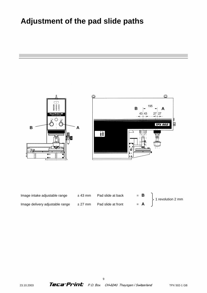
Adjustment of the pad slide paths
Image intake adjustable range ± 43 mm Pad slide at back = B Image delivery adjustable range ± 27 mm Pad slide at front = A
1 revolution 2 mm
B A
B A
10 TPX 502-1 GB 23.10.2003
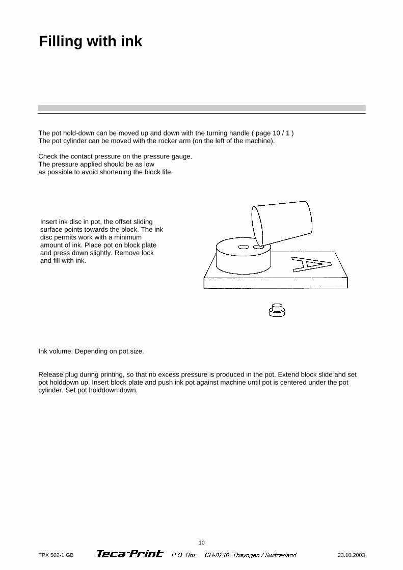
Insert ink disc in pot, the offset sliding surface points towards the block. The ink disc permits work with a minimum amount of ink. Place pot on block plate and press down slightly. Remove lock and fill with ink.
The pot hold-down can be moved up and down with the turning handle ( page 10 / 1 ) The pot cylinder can be moved with the rocker arm (on the left of the machine). Check the contact pressure on the pressure gauge. The pressure applied should be as low as possible to avoid shortening the block life.
Ink volume: Depending on pot size. Release plug during printing, so that no excess pressure is produced in the pot. Extend block slide and set pot holddown up. Insert block plate and push ink pot against machine until pot is centered under the pot cylinder. Set pot holddown down.
Filling with ink
11 23.10.2003 TPX 502-1 GB
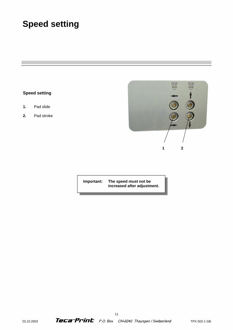
Speed setting 1. Pad slide 2. Pad stroke
1 2
Speed setting
Important: The speed must not be increased after adjustment.
12 TPX 502-1 GB 23.10.2003
Ι3 (B33)
Ι4 (B34)
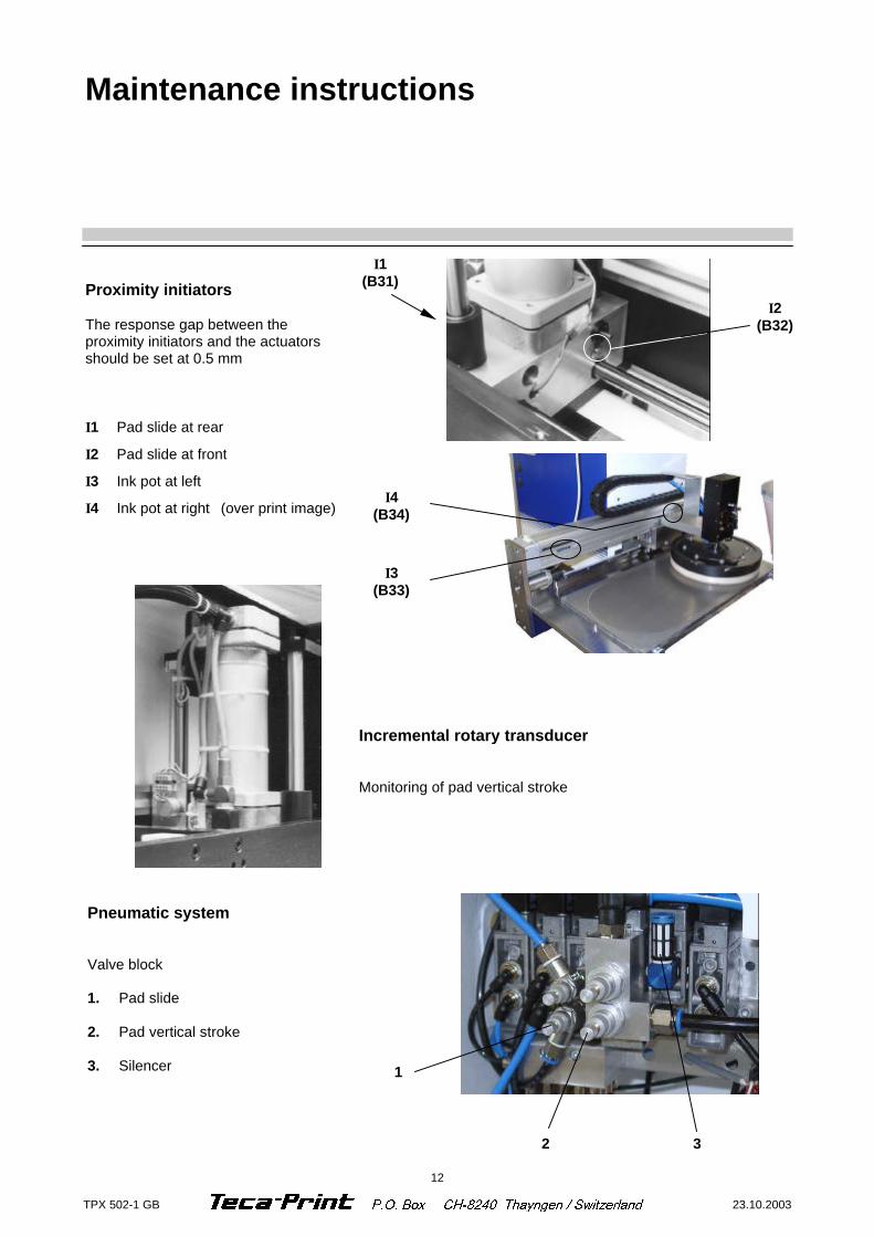
Incremental rotary transducer Monitoring of pad vertical stroke
Pneumatic system Valve block 1. Pad slide 2. Pad vertical stroke 3. Silencer
1
2 3
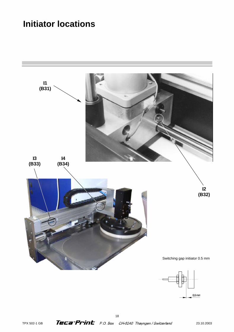
Proximity initiators The response gap between the proximity initiators and the actuators should be set at 0.5 mm
Ι1 Pad slide at rear
Ι2 Pad slide at front
Ι3 Ink pot at left
Ι4 Ink pot at right (over print image)
Maintenance instructions
Ι2 (B32)
Ι1 (B31)
13 23.10.2003 TPX 502-1 GB
Check on conditioning unit Cylinder with end-stop damping
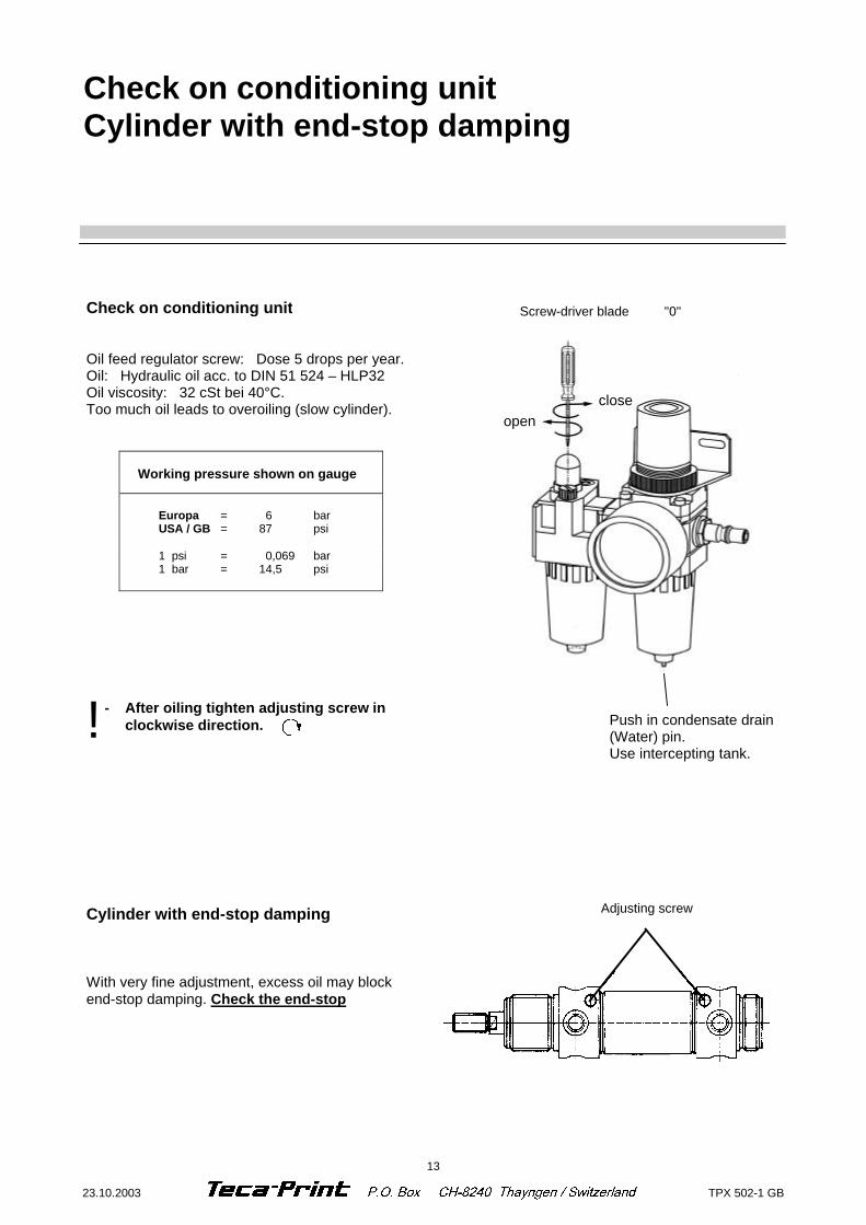
Check on conditioning unit Oil feed regulator screw: Dose 5 drops per year. Oil: Hydraulic oil acc. to DIN 51 524 – HLP32 Oil viscosity: 32 cSt bei 40°C. Too much oil leads to overoiling (slow cylinder).
Working pressure shown on gauge Europa = 6 bar USA / GB = 87 psi 1 psi = 0,069 bar 1 bar = 14,5 psi
Screw-driver blade "0"
Cylinder with end-stop damping With very fine adjustment, excess oil may block end-stop damping. Check the end-stop
Adjusting screw
close open
- After oiling tighten adjusting screw in clockwise direction. ! Push in condensate drain
(Water) pin. Use intercepting tank.

14 TPX 502-1 GB 23.10.2003
Connections, LED (TPX 350 / 500) Output power 75 Watt
Output current (24 V =) : 3,2 A
Short-circuit proof LED green LED (green) → lights up, when the power unit is ready for operation. The LED goes out, when the power unit function is impaired. Possible causes are: - There is no primary voltage at the power unit input
- The secondary load is too high and the power unit cuts off
110 V Model TPX 350 / 500 The 110 V model includes a transformer for illumination. Conversion: Part No. 821 207 424 Wiring diagram power suplay : 706 700 019
24 V =
Gnd
85 - 265 V47 - 63 Hz
Power supply unit Art. no.: 821 207 414
15 23.10.2003 TPX 502-1 GB
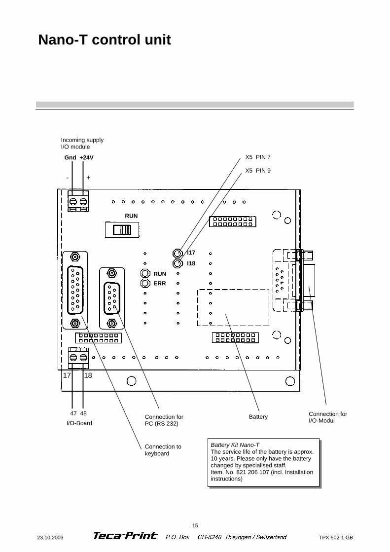
+ -
Incoming supply I/O module
I17
I18
X5 PIN 7 X5 PIN 9
RUN
ERR
RUN
Gnd +24V
Connection for PC (RS 232)
18 17
I/O-Board
47 48
Connection to keyboard
Battery
Battery Kit Nano-T The service life of the battery is approx. 10 years. Please only have the battery changed by specialised staff. Item. No. 821 206 107 (incl. Installation instructions)
Connection for I/O-Modul
Nano-T control unit
16 TPX 502-1 GB 23.10.2003
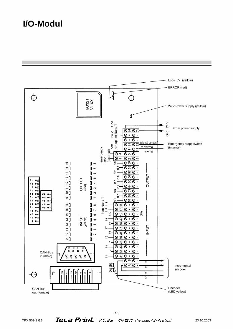
Logic 5V (yellow) ERROR (red)
24 V Power supply (yellow)
From power supply
Emergency stopp switch (internal)
Incremental encoder
Encoder (LED yellow)
CAN-Bus out (female)
I/O-Modul
(signal contact) to external internal
CAN-Bus in (male)
from
Nan
o-T
24 V
u. G
nd
to N
ano-
T
emer
genc
y st
op
(ext
erna
l) soft
run-
up
(yel
low
) (r
ed)
Gnd
24
V
17 23.10.2003 TPX 502-1 GB
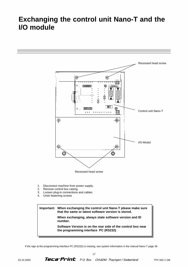
Exchanging the control unit Nano-T and the I/O module
Recessed head screw
Recessed head screw
Control unit Nano-T
I/O-Modul
1. Disconnect machine from power supply. 2. Remove control box casing. 3. Loosen plug-in connections and cables 4. Undo fastening screws
Important: When exchanging the control unit Nano-T please make sure that the same or latest software version is stored.
When exchanging, always state software version and ID number.
Software Version is on the rear side of the control box near the programming interface PC (RS232)
If the sign at the programming interface PC (RS232) is missing, see system information in the manual Nano-T page 36
18 TPX 502-1 GB 23.10.2003
Initiator locations
Ι3 (B33)
Ι4 (B34)
Switching gap initiator 0.5 mm
Ι1 (B31)
Ι2 (B32)
19 23.10.2003 TPX 502-1 GB
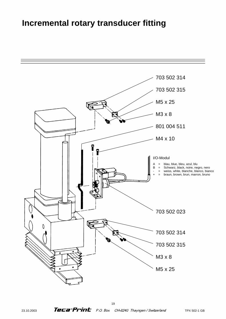
Incremental rotary transducer fitting
703 502 314 703 502 315 M5 x 25 M3 x 8 801 004 511 M4 x 10
I/O-Modul
A = blau, blue, bleu, azul, blu B = Schwarz, black, noire, negro, nero - = weiss, white, blanche, blanco, bianco + = braun, brown, brun, marron, bruno
703 502 023
703 502 314 703 502 315 M3 x 8 M5 x 25
20 TPX 502-1 GB 23.10.2003
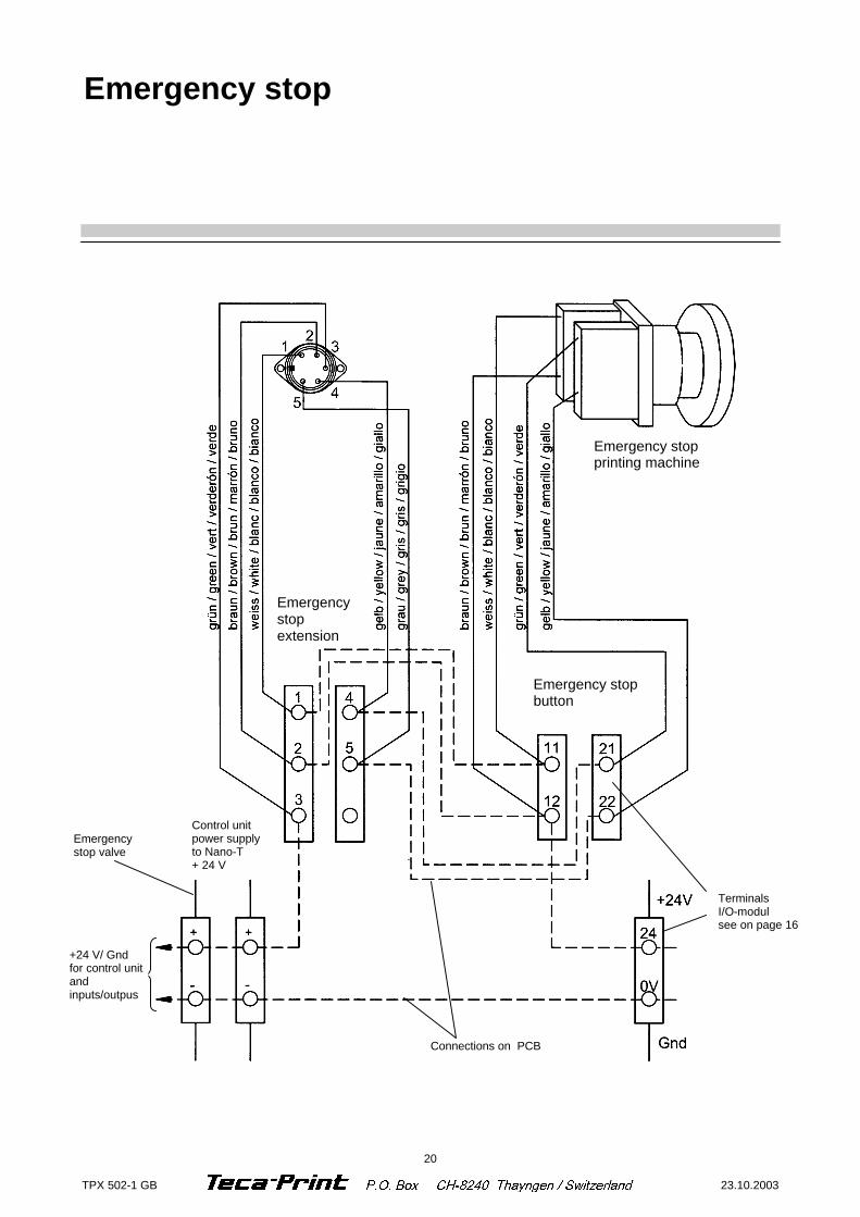
Emergency stop
Emergency stop printing machine
Emergency stop button
Emergency stop extension
+24 V/ Gnd for control unit and inputs/outpus
Emergency stop valve
Control unit power supply to Nano-T + 24 V
Connections on PCB
Terminals I/O-modul see on page 16
21 23.10.2003 TPX 502-1 GB
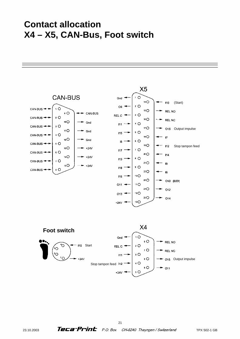
Contact allocation X4 – X5, CAN-Bus, Foot switch
Stop tampon feed
Output impulse
(Start)
Output impulse
Stop tampon feed
Foot switch
Start
22 TPX 502-1 GB 23.10.2003
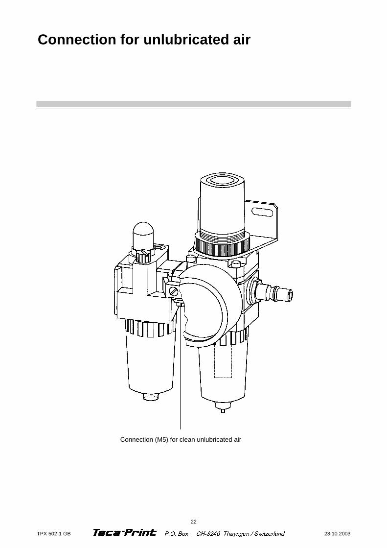
Connection for unlubricated air
Connection (M5) for clean unlubricated air

A
B
50
19.7
48120
48
TPX 350/TPX 500
H H
TPX350 / TPX 500Tamponbefestigung
706-535-003
21.01.02 WEMSTB. GEZEI.
GEPR. %
8240 THAYNGEN SWITZERLAND
TamponhalteschinePad mounting-railRail support du tampon
VerschiebesupportSlide supportSupport culissant
A B25 10 68 58 10025 20 68 58 9035 10 68 75 100
KlemmbrideDovetail adapter
Collier de serrage35 05 63
KlemmbrideDovetail adapter
Collier de serrage35 12 63
Tamponkonus mit Überwurf-mutter M16 x 1,5
Pad cone with sleeve nutCône pour support tampon avec écrou
35 01 61
Tamponhalter schmalPad holder small
Support-tampon étroit
35 50 63 H = 5035 60 63 H = 6035 70 63 H = 70
Tamponhalter zentrischPad holder centricalSupport-tampon centrique
35 25 62 H = 2535 30 62 H = 3035 40 62 H = 4035 50 62 H = 5035 60 62 H = 6035 70 62 H = 70
19.7
B
TPX 350 35 35 59TPX 500 704 502 320TPX 500/600 50 60 59
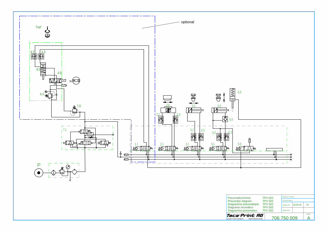
1.1
7.1
2.1 3.1 5.1 5.5
P
706 750 009
19.09.03 TA
ERSETZT DURCH
ERSATZ FUER
GEZEICHN.
GEPRUEFT
INDEX
8240 THAYNGEN SWITZERLAND
4.0
Topf
4.2 4.3
4.5
4.4
7.0
PneumatikschemaPneumatic-diagramDiagramme pneumatiqueDiagrama neumáticoDiagramma pneumatico
TPX 502TPX 502TPX 502TPX 502TPX 502
N
3.2 3.35.2 5.3
2.0 3.0 5.0
6.0
5.4
A
optional
2.32.2

5.0
5.4
3.0
3.2
5.2
1.1
2.1
3.1
5.1
5.5
3.3
5.3
706 750 010
19.09.03 TA
LageplanLayout diagramPlan de massePlano del conjuntoPlano di deposito
ERSETZT DURCH
ERSATZ FUER
GEZEICHN.
GEPRUEFT
INDEX
8240 THAYNGEN SWITZERLAND
TPX 502TPX 502TPX 502TPX 502TPX 502
4.0
2.0
6.0
A
2.32.2
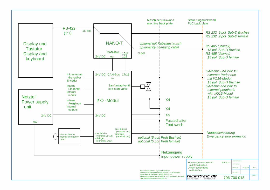
I 101/I 102
Sanftanlaufventilsoft-start valve
17/18
oder Brücke (Klemme 1+3)or bridge (terminal 1+3)
interne Ausgängeinternal outputs
interner Notausinternal emergency stop
NetzteilPower supply unit
AC
24V DC 24V DC
I/ O -Modul
RS-422 (1:1)
Display und TastaturDisplay and keyboard
24V DC
24V DC
Inkremental- drehgeberEncoder
CAN-Bus in
CAN-Bus out
15-pol.
NANO-T
Netzeinganginput power supply
optional (5 pol. Preh Buchse)optional (5 pol. Preh female)
X5FussschalterFoot swich
X4
X4
NotauserweiterungEmergency stop extension
SteuerungsrückwandPLC back plate
optional mit Kabelaustauschoptional by changing cable
9-pol.
Maschinenrückwandmachine back plate
RS 485 (Jetway) 15 pol. Sub-D BuchseRS 485 (Jetway) 15 pol. Sub-D female
CAN-Bus und 24V zu externer Peripherie mit I/O16-Modul 15 pol. Sub-D BuchseCAN-Bus and 24V to external peripherie with I/O16-Modul 15 pol. Sub-D female
RS 232 9 pol. Sub-D BuchseRS 232 9 pol. Sub-D female
706 700 018
23.04.02 WE
Steuerungskomponenten und SchnittstellenControl components and interface
ERSETZT DURCH
ERSATZ FUER
GEZEICHN.
GEPRUEFT
INDEX
8240 THAYNGEN SWITZERLAND
Technische Aenderungen vorbehaltenWe reserve the right to make any technical changesSous reserve de modifications techniquesReservato el derecho de realizar modificaciones tecnicasCon riserva di mutazioni techniche
NANO-T
oder Brücke (Klemme 11+12)or bridge (terminal 11+12)
interne Eingängeinternal inputs
O2 I11
Inkremental- drehgeberEncoder
39
34
I1
I2
I3
I4
31
32
33
I5
I6
I7
I8
I9
35
36
37
38
I11
I12
I13
I14
I1040
I17
I18
I15
I16
O1
47
48
51
I13
3
1
4
2
13
11
9
5
7
6
8
12
14
10
REL C
X51
14
3
2
15
GndI10
REL NOO9
8
5
4
6
17
16
18
19
7
20
REL NCI11O15I15I7I8I12
I14I17
23
21
19
17
15
24
22
20
18
16
25
3
1
4
2
26+24V
13
9
11
10
21
22
23
24
12
25
I9I18I6I16O10O11O12O13O14
X4
2
1
6
3
7
REL NOGnd
REL CREL NC
O12
O7
O3
O4
O5
O6
52
53
54
55
56
O10
O11
O8
O9
57
58
59
12A2
24V für Ausgänge und Logik24V for outputs and logic
O15
O16
O13
O14
GND
BA
Kanalchannel
A1
+ -
2
3
1
21
22
5
4
11
12
CAN-BUS
9
5
7
10
6
8
14
3
2
1
FS4
REL NO
X4
4
5
9
8
1
6
+24V
O15I12O11
Gnd
4
2
7
3
8
5
9
REL NCREL C
I11O15
+24V
I12O11
Belegung des CAN-Bus-SteckersPin 1-9 nach Jetter-Standard11
24V u. Gndan NANO-Tto NANO-T
-
24
-
++
-
von Netzteilfrom power supply unit
+24V
Gnd
13
1
2
3
4
5
9
10
11
12
Gnd
Gnd
Gnd
6
7
8
14
15
+24V
+24V
+24V
706
700
02023
.04.
02
WE
Ver
drah
tung
X4/
X5
- I/O
-Mod
ulW
iring
X4/
X5
- I/O
-Mod
ul
ER
SE
TZ
T D
UR
CH
ER
SA
TZ
FU
ER
GE
ZE
ICH
N.
GE
PR
UE
FT
IND
EX
8240 T
HA
YN
GE
N S
WIT
ZE
RLA
ND
Tech
nisc
he A
ende
rung
en v
orbe
halte
nW
e re
serv
e th
e rig
ht to
mak
e an
y te
chni
cal c
hang
esS
ous
rese
rve
de m
odifi
catio
ns te
chni
ques
Res
erva
to e
l der
echo
de
real
izar
mod
ifica
cion
es te
cnic
asC
on r
iser
va d
i mut
azio
ni te
chni
che
NA
NO
-T
connection of CAN-Bus-plugPin 1-9 like Jetter-Standard
Sanftan- lauf- ventilSoft start valve
Notaus- SchalterEmergency stop button
Notaus- Erwei- terungEmergency stop extension
12
230V
/50H
z
L1
S1.
0
PEN
58265 0002
L1.3
821 209 671
S1.
3
821 207 424
3
optional 110 V
423
0V
110V
nur / only TPX350/500
24V
230V
N
FG
-
L+
820
207
413
/ 820
207
414
I/O-moduleOV
703 008 102
24 V
706 700 019
24.03.03 WE
SpannungsversorgungPower suplay
ERSETZT DURCH
ERSATZ FUER
GEZEICHN.
GEPRUEFT
INDEX
8240 THAYNGEN SWITZERLAND
Technische Aenderungen vorbehaltenWe reserve the right to make any technical changesSous reserve de modifications techniquesReservato el derecho de realizar modificaciones tecnicasCon riserva di mutazioni techniche
NANO-T
B

29 23.10.2003 TPX 502-1 GB
Inputs used internally I1 (E201) Pad slide rear I2 (E202) Pad slide forward I3 (E203) Ink pot left I4 (E204) Ink pot right (over print image) I5 (E205) Raise cutter / pressure switch by pot machine Inputs for use internally and/or on X5 I6 (E206) Pin 22 Safety door switch / TFC indexing down I7 (E207) Pin 18 TFC single step I8 (E208) Pin 6 TFC On-Off I9 (E301) Pin 21 TFC indexing up TPX 500 L: Cleaning position Inputs used internally and on X5 I10 (E302) Pin 14 Machine start Inputs used on X5 I11 (E303) Pin 4 Stop continuous running / no fault cleaning tape (only in PLC mode) I12 (E304) Pin 19 Stop pad stroke Inputs for use on X5 only I13 (E305) Pin 8 Pad cleaning forward I14 (E306) Pin 20 Pad cleaning rear I15 (E307) Pin 5 PLC stop TP-slide back / RT advance rear / VTP in position / Set-up TFC I16 (E308) Pin 10 TFC advance forward I17 (E101) Pin 7 ext. start TAC / Ejector rear I18 (E102) Pin 9 Unlock TFC
Assignment of inputs of NANO-T control unit
30 TPX 502-1 GB 23.10.2003
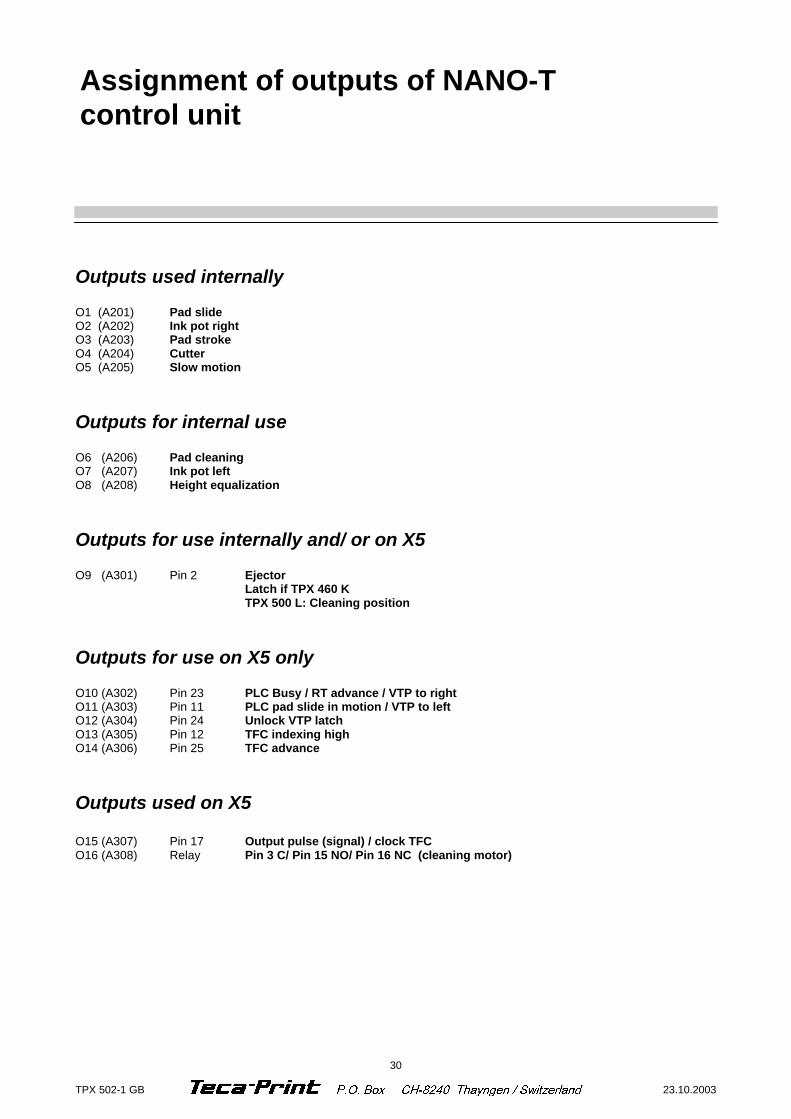
Outputs used internally O1 (A201) Pad slide O2 (A202) Ink pot right O3 (A203) Pad stroke O4 (A204) Cutter O5 (A205) Slow motion Outputs for internal use O6 (A206) Pad cleaning O7 (A207) Ink pot left O8 (A208) Height equalization Outputs for use internally and/ or on X5 O9 (A301) Pin 2 Ejector Latch if TPX 460 K TPX 500 L: Cleaning position Outputs for use on X5 only O10 (A302) Pin 23 PLC Busy / RT advance / VTP to right O11 (A303) Pin 11 PLC pad slide in motion / VTP to left O12 (A304) Pin 24 Unlock VTP latch O13 (A305) Pin 12 TFC indexing high O14 (A306) Pin 25 TFC advance Outputs used on X5 O15 (A307) Pin 17 Output pulse (signal) / clock TFC O16 (A308) Relay Pin 3 C/ Pin 15 NO/ Pin 16 NC (cleaning motor)
Assignment of outputs of NANO-T control unit
31 23.10.2003 TPX 502-1 GB
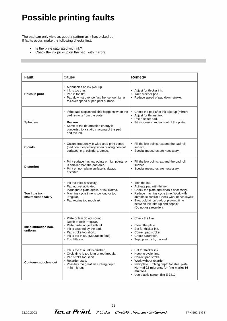
Fault Cause Remedy
Holes in print
• Air bubbles on ink pick-up. • Ink is too thin. • Pad is too flat. • Pad down-stroke too fast; hence too high a
roll-over speed of pad print surface.
• Adjust for thicker ink. • Take steeper pad. • Reduce speed of pad down-stroke.
Splashes
• If the pad is splashed, this happens when the
pad retracts from the plate. Reason: • Some of the deformation energy is
converted to a static charging of the pad and the ink.
• Check the pad after ink take-up (mirror). • Adjust for thinner ink. • Use a softer pad. • Fit an ionizing rod in front of the plate.
Clouds
• Occurs frequently in wide-area print zones
(pad float), especially when printing non-flat surfaces; e.g. cylinders, cones.
• Fill the low points, expand the pad roll
surface. • Special measures are necessary.
Distortion
• Print surface has low points or high points, or
is smaller than the pad area. • Print on non-plane surface is always
distorted.
• Fill the low points, expand the pad roll
surface. • Special measures are necessary.
Too little ink = insufficient opacity
• Ink too thick (viscosity). • Pad not yet activated. • Inadequate plate depth, or ink clotted. • Machine cycle time is too long or too
irregular. • Pad retains too much ink.
• Thin the ink. • Activate pad with thinner. • Check the plate and clean if necessary. • Reduce machine cycle time. Work with
automatic control. Check work bench layout. • Blow cold air on pad, or prolong time
between ink take-up and deposit. (Do not use retarder).
Ink distribution non-uniform
• Plate or film do not sound. Depth of etch irregular. • Plate part-clogged with ink. • Ink is crushed by the pad. • Pad stroke too short.. • Ink is too thick. (Saturation fault). • Too little ink.
• Check the film. • Clean the plate. • Set for thicker ink. • Correct pad stroke. • Check saturation. • Top up with ink; mix well.
Contours not clear-cut
• Ink is too thin. Ink is crushed. • Cycle time is too long or too irregular. • Pad stroke too short. • Retarder used. • Possibily too great an etching depth > 30 microns.
• Set for thicker ink. • Keep to cycle time. • Correct pad stroke. • Work without retarder. • New plate. Etching depth for steel plate:
Normal 22 microns, for fine marks 16 microns.
• Use plastic screen film E 7812.
Possible printing faults The pad can only yield as good a pattern as it has picked up. If faults occur, make the following checks first:
• Is the plate saturated with ink? • Check the ink pick-up on the pad (with mirror).