Embed Size (px)
Citation preview

Valve NumbersTPZ-103 to TPZ-312
TPZ Engine Air Intake Shut Down Valves(Combined Automatic Overspeed and Air PressureOperated Shut Down Bendix Types)
Selection, Application and Maintenance
CE237 (9) 0516 TPZ
A
C
Outside Diameter “X’
Input for Air Pressure Signal
Trip SpeedAdjuster Locknut
IntakeAir Flow
B
D
D
Optional ManualShut Down Cable
Vent
°
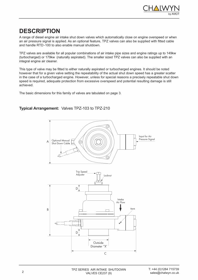
DESCRIPTIONA range of diesel engine air intake shut down valves which automatically close on engine overspeed or when an air pressure signal is applied. As an optional feature, TPZ valves can also be supplied with fitted cable and handle RTD -100 to also enable manual shutdown.
TPZ valves are available for all popular combinations of air intake pipe sizes and engine ratings up to 149kw (turbocharged) or 179kw (naturally aspirated). The smaller sized TPZ valves can also be supplied with an integral engine air cleaner.
This type of valve may be fitted to either naturally aspirated or turbocharged engines. It should be noted however that for a given valve setting the repeatability of the actual shut down speed has a greater scatter in the case of a turbocharged engine. However, unless for special reasons a precisely repeatable shut down speed is required, adequate protection from excessive overspeed and potential resulting damage is still achieved.
The basic dimensions for this family of valves are tabulated on page 3.
Typical Arrangement: Valves TPZ-103 to TPZ-210
2TPZ SERIES AIR INTAKE SHUTDOWN
VALVES CE237 (9)T: +44 (0)1284 715739 [email protected]
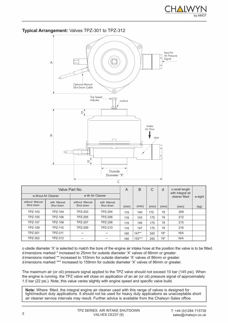
Typical Arrangement: Valves TPZ-301 to TPZ-312
Valve Part No. A B C dw ithout Air Cleaner w ith Air Cleaner
o verall lengthwith integral aircleaner fitted
(mm)
w eight
(kg)(mm) (mm) (mm) (mm)
o utside diameter ‘X’ is selected to match the bore of the engine air intake hose at the position the valve is to be fitted.d imensions marked * increased to 25mm for outside diameter ‘X’ valves of 86mm or greater.d imensions marked ** increased to 153mm for outside diameter ‘X’ valves of 86mm or greater.d imensions marked *** increased to 159mm for outside diameter ‘X’ valves of 86mm or greater.
A
C
Outside Diameter “X’
Input for Air Pressure Signal
LocknutTrip SpeedAdjuster
IntakeAir Flow
B
D
D
Optional ManualShut Down Cable
Vent
209
212
215
216
N/A
N/A
19
19
19
19
19*
19*
175
175
175
175
242
242
140
143
146
147
147**
153***
119
119
119
119
160
160
without ManualShut down
with ManualShut down
without ManualShut down
with ManualShut down
TPZ-204
TPZ-206
TPZ-208
TPZ-210
--
--
TPZ-104
TPZ-106
TPZ-108
TPZ-110
TPZ-311
TPZ-312
TPZ-203
TPZ-205
TPZ-207
TPZ-209
--
--
TPZ-103
TPZ-105
TPZ-107
TPZ-109
TPZ-301
TPZ-302
The maximum air (or oil) pressure signal applied to the TPZ valve should not exceed 10 bar (145 psi). When the engine is running, the TPZ valve will close on application of an air (or oil) pressure signal of approximately 1.5 bar (22 psi.). Note, this value varies slightly with engine speed and specific valve build.
Note: Where fitted, the integral engine air cleaner used with this range of valves is designed forlight/medium duty applications. It should not be used for heavy duty applications as unacceptable short air cleaner service intervals may result. Further advice is available from the Chalwyn Sales office.
3T: +44 (0)1284 715739 [email protected]
TPZ SERIES AIR INTAKE SHUTDOWN VALVES CE237 (9)
TPZ-103, TPZ-104, TPZ-203 & TPZ-204TPZ-105, TPZ-106, TPZ-205 & TPZ-206TPZ-107, TPZ-108, TPZ-207 & TPZ 208TPZ-109, TPZ-110, TPZ-209 & TPZ-210TPZ-301 & TPZ-311TPZ-302 & TPZ-312
VALVE PART No.Naturally
Aspirated Engines
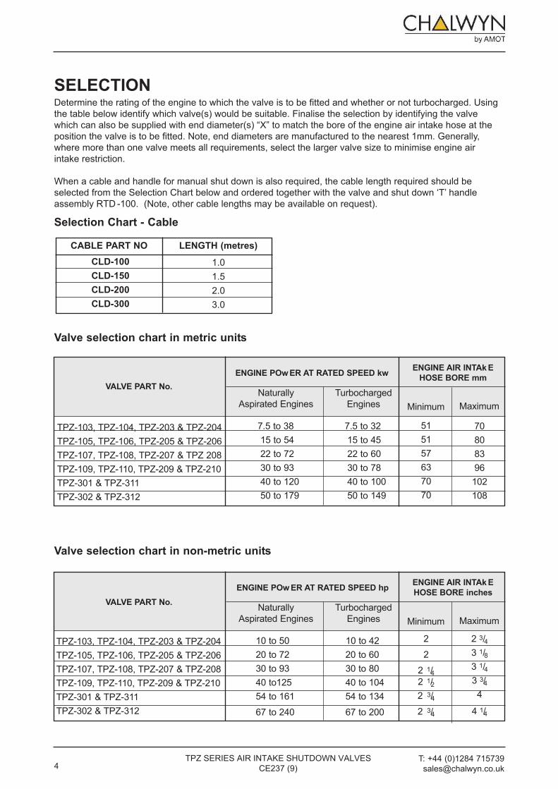
ENGINE POw ER AT RATED SPEED kw ENGINE AIR INTAk EHOSE BORE mm
Turbocharged Engines Minimum Maximum
Valve selection chart in non-metric units
Valve selection chart in metric units
70808396102108
515157637070
7.5 to 38 7.5 to 32 15 to 54 15 to 4522 to 72 22 to 6030 to 93 30 to 7840 to 120 40 to 10050 to 179 50 to 149
TPZ-103, TPZ-104, TPZ-203 & TPZ-204TPZ-105, TPZ-106, TPZ-205 & TPZ-206TPZ-107, TPZ-108, TPZ-207 & TPZ-208TPZ-109, TPZ-110, TPZ-209 & TPZ-210TPZ-301 & TPZ-311TPZ-302 & TPZ-312
VALVE PART No. Naturally Aspirated Engines
ENGINE POw ER AT RATED SPEED hp ENGINE AIR INTAk EHOSE BORE inches
Turbocharged Engines Minimum Maximum
2 3/43 1/83 1/43 3/44
4 1/4
22
2 1/42 1/22 3/42 3/4
10 to 50 10 to 42 20 to 72 20 to 6030 to 93 30 to 8040 to125 40 to 10454 to 161 54 to 13467 to 240 67 to 200
SELECTIONDetermine the rating of the engine to which the valve is to be fitted and whether or not turbocharged. Using the table below identify which valve(s) would be suitable. Finalise the selection by identifying the valve which can also be supplied with end diameter(s) “X” to match the bore of the engine air intake hose at the position the valve is to be fitted. Note, end diameters are manufactured to the nearest 1mm. Generally, where more than one valve meets all requirements, select the larger valve size to minimise engine air intake restriction.
When a cable and handle for manual shut down is also required, the cable length required should be selected from the Selection Chart below and ordered together with the valve and shut down ‘T’ handle assembly RTD -100. (Note, other cable lengths may be available on request).
CABLE PART NO LENGTH (metres)CLD-100CLD-150CLD-200CLD-300
1.01.52.03.0
Selection Chart - Cable
4TPZ SERIES AIR INTAKE SHUTDOWN VALVES
CE237 (9)T: +44 (0)1284 715739 [email protected]

1. when supplied without integral engine air clean-
ers, this family of Chalwyn valves should generally
be fitted as close to the engine air intake manifold
as possible. where an engine air intake flametrap
is also fitted, the Chalwyn valve must always be
positioned on the upstream (air cleaner) side of the
flametrap. These same requirements are generally
applicable to both naturally aspirated and tur-
bocharged engines but, in the case of a
turbocharged engine, the following may be applica-
ble.
a) Insufficient space to fit between the turbocharg-
er and engine. In this case the valve may be fit-
ted upstream of the turbocharger.
b) The turbocharger air outlet temperature is in
excess of 150°C /302°F. In this case fit the
valve downstream of the intercooler or upstream
of the turbocharger.
2. when supplied with an integral air cleaner, this
type of Chalwyn valve is fitted in place of the
existing air cleaner.
3. where more than one Chalwyn valve is fitted to an
engine, as in the case of an engine with multiple
intake pipes, a balance pipe arrangement must be
installed to connect the various intake pipes
together downstream (engine side) of the shut
down valves. Typically balance pipe diameters
should be about 30% of the diameter of the intake
pipes.
5 T: +44 (0)1284 715739 [email protected]
TPZ SERIES AIR INTAKE SHUTDOWN VALVES CE237 (9)
FITTINGSAFETY WARNING
• Care should be taken when unpacking to prevent injury.• Exhaust gases may cause permanent respiratory problems, suffocation or death. Any exhaust systems
should be piped out of enclosed areas.• Ensure that a hot engine has sufficiently cooled before commencing any work.• Ensure that the engine is prevented from being started before commencing work.• Isolate any air or oil supply being connected to the valve before commencing work.• The D Valve should be located in a safe and easily accessible position to prevent injury to the operator
due to moving parts or contact with hot surfaces while setting the valve.• Parts of the machinery on which workers are likely to move about or stand to set the Valve, should be
designed and constructed in such a way as to prevent workers from slipping, tripping or falling on or offthese parts.
• A risk assessment should be conducted before commencing work, to ensure that all hazards such asexhaust fumes, risks due to moving parts, noise and hot surfaces have been eliminated or minimised.
NOTES• No special handling requirements apply to the D Valve.• Carefully read and fully understand the installation instructions before commencing work.• Only competent personnel should install the D valve.• Wear appropriate Personal Protective Equipment including safety footwear, safety glasses, thermal
and oil resistant gloves and ear plugs.• Any spilt oil should be collected in an appropriate container and disposed of in accordance with
COSHH and local regulations.
4. When fitting, ensure the direction of air flow:a) Is in compliance with direction indicated on the body.b) Is between vertically downward and horizontal.
5. The flexible cuffs at the inlet and outlet of the valve should be of a re-inforced type, provide ade-quate support for the valve and preventexcessive vibration. If necessary, additional support brackets mounted from the engine should be considered.
6. Particular care must be taken to ensure the integrity of the intake pipework between the Chalwyn valve and intake manifold. Ideally metal pipework should be used and any gaps kept as short as possible, (taking into account any relative move-ment), and closed by re-inforced hose. The possi-bility of a hose collapse on closure of the shutdown valve should be avoided.
7. Any engine crankcase breather connections intothe intake system between the Chalwyn valve and engine or any internal crankcase breather arrangement venting directly into the engineintake ports must be sealed and replaced by an external breather system venting either to atmosphere or to the intake system upstream of the shut down valve. External breather system kits for various engine types are available from Chalwyn.
Important Notes.
a) In addition to a TPZ valve, an engine fuel stop must always be retained to enable a normal engine
shut down.
b) The collar inside the valve and the short internal cable which it anchors are factory set and must
not be loosened or adjusted.
c) For valves with the manual shut down option, if the manual shut down cable is replaced, thread the
cable inner through the drilling provided in the internal collar until the copper end stop abuts
against the collar but do not loosen or adjust the position of the collar.
6TPZ SERIES AIR INTAKE SHUTDOWN VALVES
CE237 (9)T: +44 (0)1284 715739
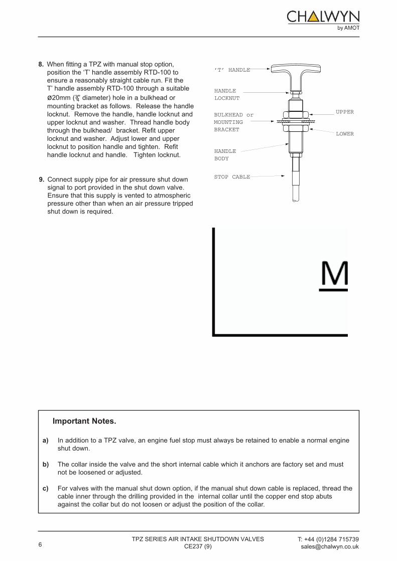
9. Connect supply pipe for air pressure shut down
signal to port provided in the shut down valve.
Ensure that this supply is vented to atmospheric
pressure other than when an air pressure tripped
shut down is required.
8. when fitting a TPZ with manual stop option,
position the ‘T’ handle assembly RTd-100 to
ensure a reasonably straight cable run. Fit the
T’ handle assembly RTd-100 through a suitable
ø20mm (3/4” diameter) hole in a bulkhead or
mounting bracket as follows. Release the handle
locknut. Remove the handle, handle locknut and
upper locknut and washer. Thread handle body
through the bulkhead/ bracket. Refit upper
locknut and washer. Adjust lower and upper
locknut to position handle and tighten. Refit
handle locknut and handle. Tighten locknut.
position the ‘T’ handle assembly RTd-100 to
ensure a reasonably straight cable run. Fit the
T’ handle assembly RTd-100 through a suitable
ø20mm (3/4” diameter) hole in a bulkhead or
mounting bracket as follows. Release the handle
locknut. Remove the handle, handle locknut and
upper locknut and washer. Thread handle body
through the bulkhead/ bracket. Refit upper
‘T’ HANDLE
HANDLE LOCKNUT
STOP CABLE
UPPER
LOWER
HANDLE BODY
BULKHEAD or MOUNTING BRACKET

Once the Chalwyn valve is installed, adjustment of the overspeed trip setting is carried out using the adjuster and locknut (refer to diagrams). Basically rotating the adjuster clockwise will increase the engine speed at which automatic shut down occurs.
As supplied, the valve will be adjusted such that shut down will generally occur well below the engine high idle speed. To increase the speed at which automatic shut down occurs, proceed as fol-lows:
1. If a remote ‘T’ handle stop control is fitted,make sure the ‘T’ handle is in the “run”position (ie. pushed in).
2. Ensure no shut down signal is being appliedby the air pressure shut down system.
3. Start engine. Slowly accelerate. Note speedat which shut down occurs.
4. Remove the hose at air inlet to Chalwyn valveto expose the adjuster and locknut(see diagram).
5. Release locknut. Turn adjuster clockwise oneturn. Tighten locknut.
6. Refit inlet hose to Chalwyn valve.
7. Start engine. Slowly accelerate. Note speedat which shut down occurs.
8. Repeat steps ‘4’ to ‘7’ until the first setting at
which the engine does not shut down at high idle speed (i.e. maximum throttle, no load). Then either:
a) Use the results of shut down speed versus
adjuster setting as a calibration check to make
a final adjustment to give the required setting
(typically 10% to 15% over high idle).
or
b) If a very precise setting is not required, turn the
adjuster a further one turn clockwise to take the
shut down above high idle speed by a suitable
margin. When using this setting procedure it
may be found that the engine occasionally
shuts down during the normal operation. If so,
turn the adjuster clockwise by a further one half
turn.
9. Ensure the adjuster locknut is fully tightened.(Use a thread lock adhesive on the locknutthreads).
10. Restart engine. Run at low/medium speed. Applyair pressure shut down signal of between 2 and10 bar. The engine should stop within a fewseconds.
11. When fitted with a remote control ‘T’ handle stopcontrol, restart the engine and operate(pull) the ’T” handle. This should stop the enginewithin a few seconds
Notes:Turbocharged Engines. When setting a valve fitted to a turbocharged engine using the preceding method, it may be found that at high engine power outputs, the engine will shut down at a lower speed than required. If this occurs, further small adjustments in steps of one half turn clockwise should be made until the problem is eliminated.
Jammed Valve.If in the course of adjusting the valve it jams on its seat, release by turning CLOCKWISE viewed from adjuster end.
7T: +44 (0)1284 715739 [email protected]
TPZ SERIES AIR INTAKE SHUTDOWN VALVES CE237 (9)
•
ADJUSTMENTSAFETY
WARNINGWhen adjusting the D Valve, take care to ensure that contact with hot surfaces or entanglement in adjacent equipment is avoided
NOTE• If a manual shut down cable assembly is fitted, ensure that excessive effort is not required to operate
the manual override.
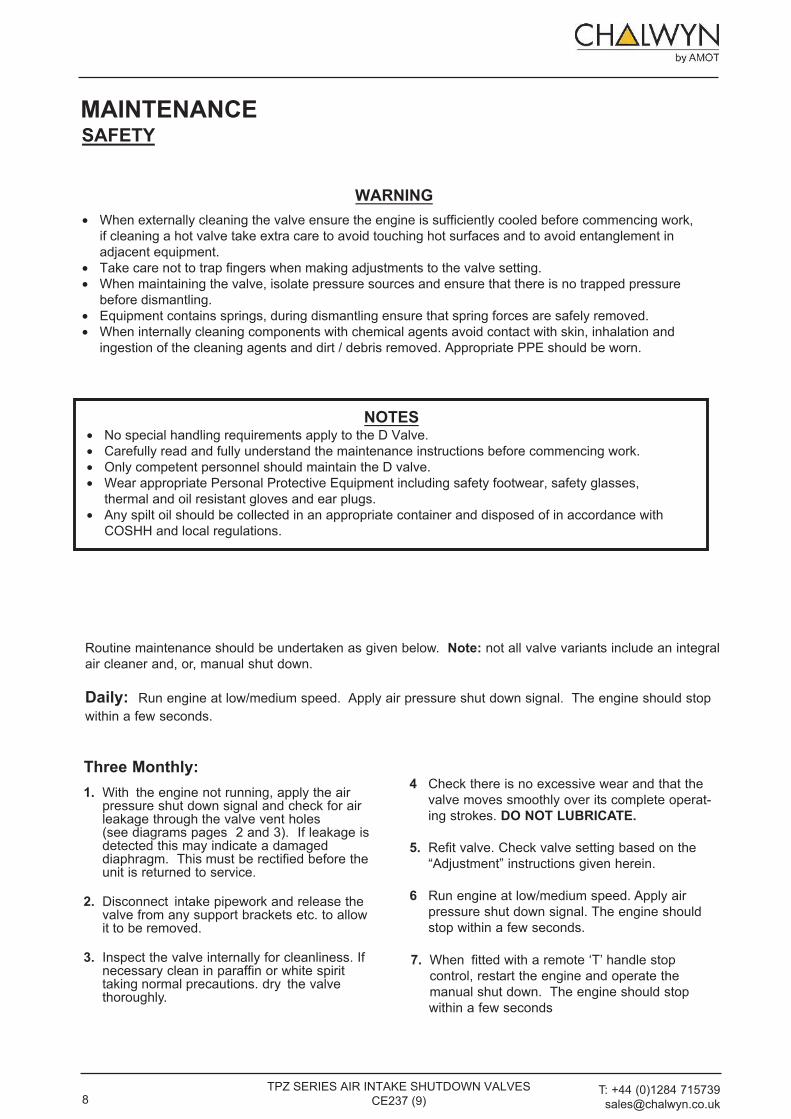
Routine maintenance should be undertaken as given below. Note: not all valve variants include an integral air cleaner and, or, manual shut down.
Daily: Run engine at low/medium speed. Apply air pressure shut down signal. The engine should stopwithin a few seconds.
Three Monthly:1. With the engine not running, apply the air
pressure shut down signal and check for airleakage through the valve vent holes(see diagrams pages 2 and 3). If leakage isdetected this may indicate a damageddiaphragm. This must be rectified before theunit is returned to service.
2. Disconnect intake pipework and release thevalve from any support brackets etc. to allowit to be removed.
3. Inspect the valve internally for cleanliness. Ifnecessary clean in paraffin or white spirittaking normal precautions. dry the valvethoroughly.
7. When fitted with a remote ‘T’ handle stoprestart the engine and operate theshut down. The engine should stop
control,manualwithin a few seconds
6 Run engine at low/medium speed. Apply airpressure shut down signal. The engine shouldstop within a few seconds.
4 Check there is no excessive wear and that thevalve moves smoothly over its complete operat-ing strokes. DO NOT LUBRICATE.
5. Refit valve. Check valve setting based on the“Adjustment” instructions given herein.
8 T: +44 (0)1284 715739 [email protected]
TPZ SERIES AIR INTAKE SHUTDOWN VALVES CE237 (9)
MAINTENANCESAFETY
WARNING• When externally cleaning the valve ensure the engine is sufficiently cooled before commencing work,
if cleaning a hot valve take extra care to avoid touching hot surfaces and to avoid entanglement inadjacent equipment.
• Take care not to trap fingers when making adjustments to the valve setting.• When maintaining the valve, isolate pressure sources and ensure that there is no trapped pressure
before dismantling.• Equipment contains springs, during dismantling ensure that spring forces are safely removed.• When internally cleaning components with chemical agents avoid contact with skin, inhalation and
ingestion of the cleaning agents and dirt / debris removed. Appropriate PPE should be worn.
NOTES• No special handling requirements apply to the D Valve.• Carefully read and fully understand the maintenance instructions before commencing work.• Only competent personnel should maintain the D valve.• Wear appropriate Personal Protective Equipment including safety footwear, safety glasses,
thermal and oil resistant gloves and ear plugs.• Any spilt oil should be collected in an appropriate container and disposed of in accordance with
COSHH and local regulations.
Chalwyn by [email protected]
A division of Roper Industries limited
UkBury St Edmunds, IP33 3SZTel: +44 (0)1284 715739 Fax: +44 (0)1284 715747
USAhouston, TX 77064Tel: +1 (281) 940 1800 Fax: +1 (713) 559 9419
Integral Engine Air Cleaner (where fitted) Replace air cleaner element at the periodsrecommended by the engine manufacturer. (Spare elements are available from Chalwyn).
Important Notes:The three monthly routine maintenance period requirement is dependent on the operating conditions to which the equipment is exposed and, by experience, may need to be varied.
Any maintenance problems not covered by the above routine maintenance schedule should be discussed with your Chalwyn distributor before any repair work is undertaken.