Embed Size (px)
Citation preview
ETSI TR 102 522 V1.1.1 (2006-12)
Technical Report
Electromagnetic compatibilityand Radio spectrum Matters (ERM);
Short Range Devices (SRD);Equipment for Detecting Movement;
Radio equipment operating in thefrequency range 17,1 GHz to 17,3 GHz;
System Reference Document forGround Based Synthetic Aperture Radar (GBSAR)

ETSI
ETSI TR 102 522 V1.1.1 (2006-12) 2
Reference DTR/ERM-RM-052
Keywords radar, SRD, SRDOC
ETSI
650 Route des Lucioles F-06921 Sophia Antipolis Cedex - FRANCE
Tel.: +33 4 92 94 42 00 Fax: +33 4 93 65 47 16
Siret N° 348 623 562 00017 - NAF 742 C
Association à but non lucratif enregistrée à la Sous-Préfecture de Grasse (06) N° 7803/88
Important notice
Individual copies of the present document can be downloaded from: http://www.etsi.org
The present document may be made available in more than one electronic version or in print. In any case of existing or perceived difference in contents between such versions, the reference version is the Portable Document Format (PDF).
In case of dispute, the reference shall be the printing on ETSI printers of the PDF version kept on a specific network drive within ETSI Secretariat.
Users of the present document should be aware that the document may be subject to revision or change of status. Information on the current status of this and other ETSI documents is available at
http://portal.etsi.org/tb/status/status.asp
If you find errors in the present document, please send your comment to one of the following services: http://portal.etsi.org/chaircor/ETSI_support.asp
Copyright Notification
No part may be reproduced except as authorized by written permission. The copyright and the foregoing restriction extend to reproduction in all media.
© European Telecommunications Standards Institute 2006.
All rights reserved.
DECTTM, PLUGTESTSTM and UMTSTM are Trade Marks of ETSI registered for the benefit of its Members. TIPHONTM and the TIPHON logo are Trade Marks currently being registered by ETSI for the benefit of its Members. 3GPPTM is a Trade Mark of ETSI registered for the benefit of its Members and of the 3GPP Organizational Partners.
ETSI
ETSI TR 102 522 V1.1.1 (2006-12) 3
Contents
Intellectual Property Rights ................................................................................................................................5
Foreword.............................................................................................................................................................5
Introduction ........................................................................................................................................................5
1 Scope ........................................................................................................................................................6
2 References ................................................................................................................................................6
3 Definitions, symbols and abbreviations ...................................................................................................7 3.1 Definitions..........................................................................................................................................................7 3.2 Symbols..............................................................................................................................................................7 3.3 Abbreviations .....................................................................................................................................................7
4 Executive summary ..................................................................................................................................8 4.1 Status of the present document...........................................................................................................................8 4.2 Market information.............................................................................................................................................8 4.3 Technical system description .............................................................................................................................8
5 Current regulations...................................................................................................................................9
6 Proposed regulations ................................................................................................................................9
7 Main conclusions....................................................................................................................................10
8 Expected ETSI and ECC actions............................................................................................................10
Annex A: Detailed market information ..............................................................................................11
A.1 Range of applications .............................................................................................................................11
A.2 Market size and value.............................................................................................................................12 A.2.1 Terrain monitoring application.........................................................................................................................12 A.2.2 Structures monitoring application ....................................................................................................................13
A.3 Deployment and usage activities............................................................................................................13 A.3.1 Terrain monitoring ...........................................................................................................................................13 A.3.2 Structural monitoring .......................................................................................................................................13
Annex B: Technical information .........................................................................................................14
B.1 General Technical Description...............................................................................................................14
B.2 Detailed technical description ................................................................................................................14 B.2.1 Assessment of alternative bands.......................................................................................................................17 B.2.1.1 Alternative operation on 24 GHz................................................................................................................17 B.2.1.2 Alternative operation on 13.7 GHz.............................................................................................................18
B.3 Applications description.........................................................................................................................18 B.3.1 Structure monitoring application......................................................................................................................18 B.3.1.1 Structure monitoring examples ...................................................................................................................19 B.3.1.1.1 Static test example.................................................................................................................................19 B.3.1.1.2 Dynamic test example ...........................................................................................................................20 B.3.1.2 Terrain monitoring application ...................................................................................................................23 B.3.1.2.1 Terrain monitoring examples ................................................................................................................24 B.3.1.2.1.1 Tessina landslide measurement survey............................................................................................24 B.3.1.2.1.2 Citrin landslide measurement survey...............................................................................................25
B.4 Justification for radiated power and bandwidth requirement .................................................................26 B.4.1 Radiated Power requirement ............................................................................................................................26 B.4.2. Bandwidth requirement ....................................................................................................................................27
B.5 GBSAR Unwanted emissions ................................................................................................................28
ETSI
ETSI TR 102 522 V1.1.1 (2006-12) 4
B.6 Information on current version of relevant ETSI standard.....................................................................29
Annex C: Expected compatibility issues .............................................................................................30
C.1 Coexistence issues..................................................................................................................................30
C.2 Current ITU allocations..........................................................................................................................30
C.3 Sharing issues.........................................................................................................................................30
History ..............................................................................................................................................................31
ETSI
ETSI TR 102 522 V1.1.1 (2006-12) 5
Intellectual Property Rights IPRs essential or potentially essential to the present document may have been declared to ETSI. The information pertaining to these essential IPRs, if any, is publicly available for ETSI members and non-members, and can be found in ETSI SR 000 314: "Intellectual Property Rights (IPRs); Essential, or potentially Essential, IPRs notified to ETSI in respect of ETSI standards", which is available from the ETSI Secretariat. Latest updates are available on the ETSI Web server (http://webapp.etsi.org/IPR/home.asp).
Pursuant to the ETSI IPR Policy, no investigation, including IPR searches, has been carried out by ETSI. No guarantee can be given as to the existence of other IPRs not referenced in ETSI SR 000 314 (or the updates on the ETSI Web server) which are, or may be, or may become, essential to the present document.
Foreword This Technical Report (TR) has been produced by ETSI Technical Committee Electromagnetic compatibility and Radio spectrum Matters (ERM).
Introduction The present document covers Ground Based Synthetic Aperture Radar (GBSAR) operating in the frequency range 17,1 GHz to 17,3 GHz. The GBSAR is using a Stepped Frequency CW (SF-CW) radar technique and is used for a wide range of applications for detection of movement within the following main categories:
• Structure monitoring, for example:
- Bridge movement and resonance analyses;
- Building and bridge construction, civil engineering.
• Terrain monitoring, for example:
- Monitoring of volcanoes, earthquakes and land slides.
For additional and further description of applications, see clause A.1.
The purpose of producing the present document is to lay a foundation for industry to quickly bring innovative and useful products to the market while avoiding any harmful interference with other services and applications.
The present document includes necessary information to support the co-operation under the MoU between ETSI and the Electronic Communications Committee (ECC) of the European Conference of Post and Telecommunications Administrations (CEPT).

ETSI
ETSI TR 102 522 V1.1.1 (2006-12) 6
1 Scope The present document provides information on the intended applications; the technical parameters and the radio spectrum requirements for GBSAR based Stepped Frequency CW (SF-CW) radar, operating in the frequency band:
• 17,1 GHz to 17,3 GHz.
The present document describes a GBSAR system that is used for detection of movement.
The scope is limited to radar equipment operated as a short range device.
The radar applications in the present document are not intended for communications purposes but exclusively for detection of movement related to safety of structures potentially effecting the protection of workers and the general public. A few examples of applications are given below but are limited to:
• static and dynamic load analyses of constructions like bridges and buildings;
• landslide monitoring;
• volcano and earthquake movement detection;
• urban area subsidence detection.
Additional information on GBSAR is given in the following clauses:
• Annex A: Detailed market information;
• Annex B: Technical information;
• Annex C: Expected compatibility issues.
2 References For the purposes of the present document the following references apply:
NOTE: While any hyperlinks included in this clause were valid at the time of publication ETSI cannot guarantee their long term validity.
[1] CEPT/ERC Recommendation 70-03: "Relating to the use of Short Range Devices (SRD)".
[2] ITU-R Radio Regulations.
[3] ITU-R Recommendation SM.1538-2: "Technical and operating parameters and spectrum requirements for short-range radiocommunication devices".
[4] ETSI EN 300 440-1: "Electromagnetic compatibility and Radio spectrum Matters (ERM); Short Range Devices (SRD); Radio equipment to be used in the 1 GHz to 40 GHz frequency range; Part 1: Technical characteristics and test methods".
[5] CEPT/ERC Recommendation 74-01: "Unwanted Emissions in the Spurious Domain".
ETSI
ETSI TR 102 522 V1.1.1 (2006-12) 7
3 Definitions, symbols and abbreviations
3.1 Definitions For the purposes of the present document, the following terms and definitions apply:
cross range resolution: ability to resolve two targets at same range
range resolution: ability to resolve two targets at different ranges
stepped frequency CW radar: Continuous Wave radar transmitting a finite sequence of N different frequencies
3.2 Symbols For the purposes of the present document, the following symbols apply:
B bandwidth c speed of light f0 centre frequency GRANGE gain given by the range compression process of the signal
GSAR processing gain given by the SAR synthesis
L additional pathloss from e.g. water loss, scintillation, additional atmospheric loss λ system wavelength σ0 backscattering coefficient of the terrain
σr measurement accuracy of a pixel displacement
PR Received signal from reflecting target R range S pixel area at distance R Tdw dwell time duration
X cross-range structure dimension or cross- range illuminated area
3.3 Abbreviations For the purposes of the present document, the following abbreviations apply:
CEPT European Conference of Post and Telecommunications CH Switzerland dB Decibel DEM Digital Elevation Model e.i.r.p. equivalent isotropically radiated power ECC Electronic Communications Committee ERC European Radiocommunications Committee ETSI European Telecommunications Standards Institute GB Ground Based GBSAR Ground Based Synthetic Aperture Radar IQ Inphase and Quadrature ISM Industrial, Scientific and Medical ITU International Telecommunications Union MoU Memorandum of Understanding NL The NetherLands RCS Radar Cross Section rms root mean square SAR Synthetic Aperture Radar SF-CW Stepped Frequency - Continuous Wave SNR Signal to Noise Ratio SRD Short Range Device SRDoc System Reference Document
ETSI
ETSI TR 102 522 V1.1.1 (2006-12) 8
WGFM Working Group Frequency Management
4 Executive summary The present document provides information on GBSAR system. GBSAR is a tool which can provide additional protection during the construction and maintenance of buildings, bridges, tunnels and monitor environmental structure changes. GBSAR provides high accuracy and outstanding reliability.
The objective of designers and operators of GBSAR is to direct radar signals towards the surface of a construction or environment to detect any movement or resonance of the object. GBSAR does not communicate any information via the radar signal to any other equipment; therefore no protocol communications standard is required.
The GBSAR equipment operates under the Short Range Devices rules of not claiming protection from other radio communication services operating in the same or adjacent bands.
Recognizing that GBSAR may have indirect safety of human life implications, manufacturers should pay particular attention to the potential for interference when selecting parameters for GBSAR.
4.1 Status of the present document Version, V 1.0.0_0.1.1, of the TR was approved by ERM-TG28#14 and was submitted to WG ERM-RM for approval via correspondence. Comments were received from the NL and CH administrations. These comments were dealt with in version V 1.1.1_1.2.1 of the document, which was forwarded to CEPT . In order to take into account further comments, including those received during the meeting of WG FM of CEPT (September 2006), a new version (1.1.1_1.2.2) was produced.
The present version is offered to TC-ERM in view of its approval as TR 102 522 and its publication.
4.2 Market information Interferometric analysis and Synthetic Aperture Radar (SAR) synthesis are two powerful data processing techniques which have nowadays been used for airborne and space-borne remote sensing systems with the objective of detecting ground displacement.
These two techniques, based on processing of data acquired by electromagnetic microwaves reflected by targets, can be exploited by Ground Based (GB) system (in the following named GBSAR system) to perform:
• Structures monitoring.
• Terrain monitoring.
The deployment of the system is up to 0,6 and 6 units/1 000 km2 for structure and terrain monitoring respectively.
For detailed market information, see annex A.
4.3 Technical system description A GBSAR system exploits, as earth monitoring satellites, interferometric analysis and Synthetic Aperture Radar (SAR) techniques to provide displacement maps for terrain or structure monitoring applications. In particular:
• the interferometric technique provides data on object displacement by comparing phase information, collected in different time periods, of reflected waves from the object, providing a measure of the displacement with an accuracy of less than 1 mm;
• the Synthetic Aperture Radar (SAR) technique enables the system to provide high resolution images. High range resolution is obtained using large transmitted bandwidth whereas high cross range resolution is derived, only for the terrain monitoring applications, exploiting the movement of the physical antenna along a straight trajectory.
ETSI
ETSI TR 102 522 V1.1.1 (2006-12) 9
The GBSAR system is based on a Step Frequency - Continuous Wave (SF-CW) coherent radar that transmits, step by step, continuous waves at discrete frequency values in a frequency range of bandwidth B. By this method an interference mitigation is offered as the transmission is only on for a short time at each discrete frequency. It is important to observe that the transmitted signal is a sequence of non-modulated frequency steps, whose total frequency range (bandwidth) is controlled by the equipment management system. The bandwidth can be adjusted between 100 MHz and 200 MHz when required by the measurement.
For detailed technical information on GBSAR, see clause B.
5 Current regulations There is currently no regulation for GBSAR in the frequency range 17,1 GHz to 17,3 GHz.
The current annex 6 ("Equipment for Detecting Movement and Equipment for Alert") of CEPT/ERC Recommendation 70-03 [1] contains provisions for operation in the following bands:
• 24,05 GHz to 24,25 GHz at a power level of 100 mW.
• 13,4 GHz to 14,0 GHz at a power level of 25 mW.
However, these power levels are insufficient to permit the operation of GBSAR capable of providing the range resolution and displacement accuracy necessary to provide industrial users of GBSAR with the capability they require.
An assessment of these alternative bands (13 GHz and 24 GHz) is given in clause B.2.1.
It has to be noted that although the frequency range 16,6 to 17,1 GHz is allocated to RADIOLOCATION designated as Military Harmonized band for land, airborne and naval radars, the following range 17,1 to 17,3 GHz is allocated to RADIOLOCATION as a designated band for military radars shared with civil uses in accordance with the provisions in the European Common Allocation Table.
6 Proposed regulations It is proposed to permit GBSAR to operate with the specifications in table 1.
Table 1: Proposed radio interface requirements for GBSAR systems
Frequency band
Max. frequency range
Max. Conducted power
Max. radiated power e.i.r.p.
17,1 GHz to 17,3 GHz 200 MHz +6 dBm +26 dBm
Article No. 4.4 of the Radio Regulations [2] has been relied upon by national administrations in many contexts to authorize applications not conforming to the Table of Frequency Allocations in the Radio Regulations (e.g. Short Range Devices which are operated in ISM frequency bands). GBSAR equipment, as described in the present document, might also be operated under Article Radio Regulations No. 4.4. as long as specific operational conditions are met.
Procedures for administrating and ensuring adherence to regulations should be kept to a minimum, both for the regulator as well as for the users of GBSAR; particularly as it should be considered that the most important aspect of GBSAR operation is an "immediate deployment" for critical or emergency situations such as slopes, bridge collapsing risks etc. Considering this and also taking into account those aspects as summarized in clause 5, it is fully believed that GBSAR falls within the ERC/REC 70-03 [1] general stipulated principle of SRD with no-licence requirement. Therefore, a general, non-individual, licence-exempt arrangement is desired.
The requested frequency band 17,1 GHz to 17,3 GHz is currently designated to wide band transmission systems in CEPT/ERC 70-03 [6], annex 3. However, since this application has not used this band yet, it is suggested to share this spectrum with the proposed system by adding the GBSAR application to the specific annex 6 of ERC/REC 70-03 [1] for Detecting Movement and Alert together with an increase of the power to 400 mW e.i.r.p.
ETSI
ETSI TR 102 522 V1.1.1 (2006-12) 10
7 Main conclusions GBSAR will be used by many industries and government administrations to increase the safety of workers and general public by measuring the amount of movement for constructions or changes in the terrain, for details of applications, see clause A.1.
The current available regulations are insufficient to permit the operation of GBSAR capable of providing the range resolution and displacement accuracy necessary required by industrial users of GBSAR.
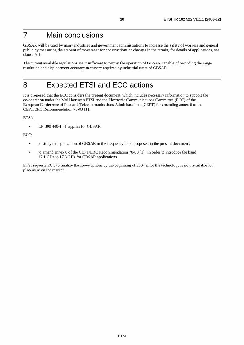
8 Expected ETSI and ECC actions It is proposed that the ECC considers the present document, which includes necessary information to support the co-operation under the MoU between ETSI and the Electronic Communications Committee (ECC) of the European Conference of Post and Telecommunications Administrations (CEPT) for amending annex 6 of the CEPT/ERC Recommendation 70-03 [1].
ETSI:
• EN 300 440-1 [4] applies for GBSAR.
ECC:
• to study the application of GBSAR in the frequency band proposed in the present document;
• to amend annex 6 of the CEPT/ERC Recommendation 70-03 [1] , in order to introduce the band 17,1 GHz to 17,3 GHz for GBSAR applications.
ETSI requests ECC to finalize the above actions by the beginning of 2007 since the technology is now available for placement on the market.

ETSI
ETSI TR 102 522 V1.1.1 (2006-12) 11
Annex A: Detailed market information
A.1 Range of applications Interferometric analysis and SAR synthesis are two powerful data processing techniques which have nowadays been used for airborne and space-borne remote sensing systems with the objective of detecting ground displacement.
These two techniques, based on processing of data acquired by electromagnetic microwaves reflected by targets, can be exploited by Ground Based (GB) system (in the following named GBSAR system) to perform:
• Structures monitoring.
• Terrain monitoring.
For structure monitoring applications, a GBSAR system is used for:
• Static monitoring:
- static tests;
- time-dependent displacement or deformation monitoring;
- displacement or deformation detection during building work.
• Dynamic monitoring:
- resonance frequency detection;
- vibration mode detection.
Possible users of the GBSAR system may include:
• Service companies who provide builders with static and dynamic load tests of structures.
• Architects involved in renovation works.
• Building surveyors.
• Civil Engineering University Departments.
• Public agencies with the task of infrastructures management.
• Civil Engineering companies.
• Building companies.
For terrain monitoring applications, the GBSAR system is used for:
• Landslide monitoring.
• Volcano movement detection.
• Urban area subsidence detection.
Possible users of the GBSAR system for terrain monitoring application:
• Geologists.
• Public agencies with the task of environmental management.
• Earth Observation University Departments.
ETSI
ETSI TR 102 522 V1.1.1 (2006-12) 12
Some of the main advantages of the GBSAR system are:
• High measuring accuracy.
• Easy installation.
• High reliability.
• Non-contacting measuring principle (remote sensing).
• Provision of displacement information related to all the illuminated area with high resolution image.
• For terrain monitoring, the GBSAR system allows the operator:
- To monitor landslides of some km2 dimension, with a displacement accuracy of 1 mm.
- To monitor completely unreachable instability of slopes, on which it is impossible to install sensors.
- To monitor slopes far away from the installation sites, thanks to the up to 3 km range of the system.
- To perform continuous monitoring due to the ability to leave the GBSAR system operating even without the presence of a human operator; the system control can be performed from remote sites using wireless links.
- To monitor different landslides using the same device; existing techniques require the need to install new sensor networks for each landslide.
- The possibility to reuse the same instrument for different landslides is useful for survey of large areas and is cost-effective.
• For structures monitoring, the GBSAR system allows the operator:
- To monitor structures of some hundred meters length.
- To use GBSAR in emergency situations as a sensor in warning systems.
A.2 Market size and value The estimate of the size and value of the GBSAR system market has to be divided for the two different market shares to which the devices are addressed.
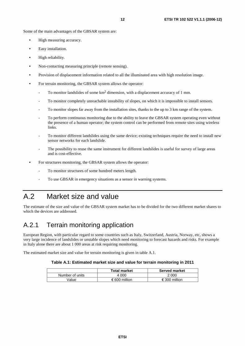
A.2.1 Terrain monitoring application European Region, with particular regard to some countries such as Italy, Switzerland, Austria, Norway, etc, shows a very large incidence of landslides or unstable slopes which need monitoring to forecast hazards and risks. For example in Italy alone there are about 1 000 areas at risk requiring monitoring.
The estimated market size and value for terrain monitoring is given in table A.1.
Table A.1: Estimated market size and value for terrain monitoring in 2011
Total market Served market Number of units 4 000 2 000
Value € 600 million € 300 million
ETSI
ETSI TR 102 522 V1.1.1 (2006-12) 13
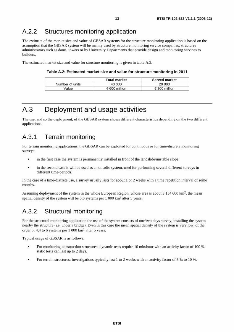
A.2.2 Structures monitoring application The estimate of the market size and value of GBSAR systems for the structure monitoring application is based on the assumption that the GBSAR system will be mainly used by structure monitoring service companies, structures administrators such as dams, towers or by University Departments that provide design and monitoring services to builders.
The estimated market size and value for structure monitoring is given in table A.2.
Table A.2: Estimated market size and value for structure monitoring in 2011
Total market Served market Number of units 40 000 20 000
Value € 600 million € 300 million
A.3 Deployment and usage activities The use, and so the deployment, of the GBSAR system shows different characteristics depending on the two different applications.
A.3.1 Terrain monitoring For terrain monitoring applications, the GBSAR can be exploited for continuous or for time-discrete monitoring surveys:
• in the first case the system is permanently installed in front of the landslide/unstable slope;
• in the second case it will be used as a nomadic system, used for performing several different surveys in different time-periods.
In the case of a time-discrete use, a survey usually lasts for about 1 or 2 weeks with a time repetition interval of some months.
Assuming deployment of the system in the whole European Region, whose area is about 3 154 000 km2, the mean spatial density of the system will be 0,6 systems per 1 000 km2 after 5 years.
A.3.2 Structural monitoring For the structural monitoring application the use of the system consists of one/two days survey, installing the system nearby the structure (i.e. under a bridge). Even in this case the mean spatial density of the system is very low, of the order of 4,4 to 6 systems per 1 000 km2 after 5 years.
Typical usage of GBSAR is as follows:
• For monitoring construction structures: dynamic tests require 10 min/hour with an activity factor of 100 %; static tests can last up to 2 days.
• For terrain structures: investigations typically last 1 to 2 weeks with an activity factor of 5 % to 10 %.
ETSI
ETSI TR 102 522 V1.1.1 (2006-12) 14
Annex B: Technical information
B.1 General Technical Description Surface change is a large-scale coherent change common to several adjacent pixels. By this it is meant that, within a given pixel, the position of radar scatterers has not changed to any significant degree, but the ensemble of scatterers (for example the entire ground surface within that pixel, as well as some adjacent ones) has moved up, down, or sideways in some correlated fashion. It is then possible to perform a phase comparison of the two images. The differential phase contains information on the range change to the radar antenna, thus providing information on the surface change, precise to a fraction of a radar wavelength, or to a few millimetres to centimetres for typical radars. To measure surface displacement to this precision requires a relatively accurate a priori estimate of topography in the region and information on the position and orientation of the antennas during each image acquisition.
Measurement of surface displacement with SAR interferometry depends on the nature of the surface change.
Two important necessary conditions for detecting and measuring surface change with SAR can be restated:
• Changes between successive images must not be too large, specifically the displacement gradient across a pixel must fall within some value.
• The radar-scattering characteristics within each pixel must remain similar in the time between the two image acquisitions, specifically the root-mean-square (rms) position of the surface scatterers within a pixel must remain constant within a fraction, say 10 % to 20 %, of the radar wavelength.
The great advantage of SAR is that the observations are acquired with virtually complete spatial coverage, rather than the sparse observations inherent in conventional (including GPS/Galileo) geodesy.
B.2 Detailed technical description As mentioned above the GBSAR system exploits, as earth monitoring satellites, interferometric analysis and Synthetic Aperture Radar (SAR) techniques to provide displacement maps for terrain or structure monitoring applications. In particular:
• the interferometric technique provides data on object displacement by comparing phase information, collected in different time periods, of reflected waves from the object, providing a measure of the displacement with an accuracy of less than 1 mm;
• the Synthetic Aperture Radar (SAR) technique enables the system to provide high resolution images. High range resolution is obtained using large transmitted bandwidth whereas high cross range resolution is derived, only for the terrain monitoring applications, exploiting the movement of the physical antenna along a straight trajectory.
The GBSAR system is based on a Step Frequency to Continuous Wave (SF-CW) coherent radar that transmits, step by step, continuous waves at discrete frequency values in a frequency range of bandwidth B. It is important to observe that the transmitted signal is a sequence of non-modulated frequency steps, whose total frequency bandwidth is controlled by the management system and can be decreased from 200 MHz down to 100 MHz.
The GBSAR system comprises the following main modules:
• The sensor module consists of the transmitter, receiver and necessary antennas. The electronics generate and receive microwaves on a desired frequency using the SF-CW principle. After receiving the reflected microwave signal the detected analogue signal is processed using an advanced digital signal processing to generate the desirable output. The output is then provided to the user by use of the PC linked to the sensor module.
ETSI
ETSI TR 102 522 V1.1.1 (2006-12) 15
• The power supply module, consisting of two 12V batteries for a self-sufficient use of the GBSAR system when mains supply is not available. The power supply module is provided with input plugs for external recharge by mains supply or solar cell panels.
• The system management and data acquisition module, consisting of a PC provided with management software. The management software allows the operator to set the system parameters and to view the first rough result of the monitoring campaign.
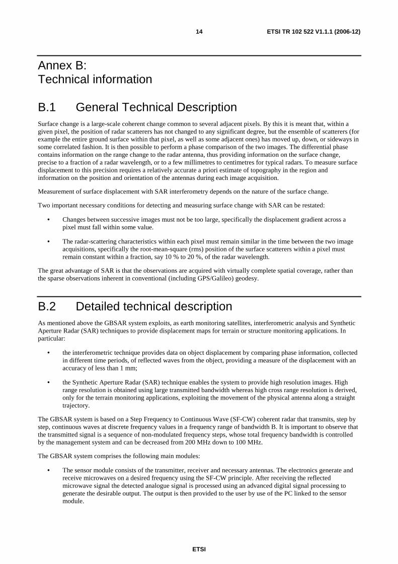
• For the terrain monitoring application, the GBSAR system is provided with a moving module, composed of a 2 meter track along which the sensor modules moves see figure B.1.
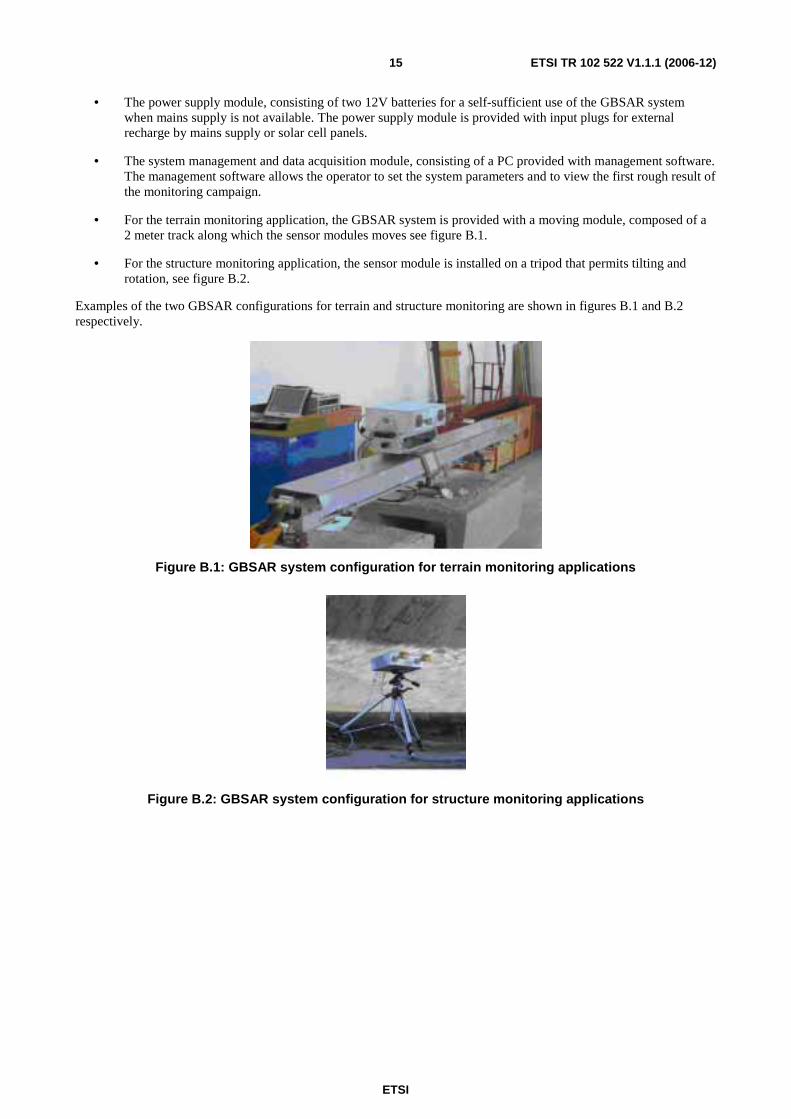
• For the structure monitoring application, the sensor module is installed on a tripod that permits tilting and rotation, see figure B.2.
Examples of the two GBSAR configurations for terrain and structure monitoring are shown in figures B.1 and B.2 respectively.
Figure B.1: GBSAR system configuration for terrain monitoring applications
Figure B.2: GBSAR system configuration for structure monitoring applications

ETSI
ETSI TR 102 522 V1.1.1 (2006-12) 16
The main technical characteristics of GBSAR system is summarized in table B.1.
Table B.1: GBSAR system technical characteristics
Parameter Value Signal type SF-CW Centre frequency (f0) 17,200 GHz
Frequency range (Bandwidth (BW) 200 MHz Frequency step increment 30 kHz to 300 kHz Dwell time duration Tdw 3,3 µs to 33 µs
Unwanted emissions in the spurious domain -60 dBc Unwanted emissions in the Out of Band domain ≤ 40 dBc (note) Max usable range - 4 km Radiated power, e.i.r.p. 26 dBm Polarization Linear VV Antenna height from ground 1 m Mobility type Nomadic system NOTE: For details see spectrum mask in figure B.16.
The technical characteristics of the GBSAR system allows the operative characteristics summarized in table B.2 below:
Table B.2: GBSAR system operative characteristics
Application Terrain monitoring Structure monitoring Frequency band 17,1 to17,3 GHz 17,1 to 17,3 GHz Radar type SF CW SF CW Use Ground-based Ground-based SAR capability Yes Yes Interferometric capability Yes Yes Operating distance 0,2 to 4 km 10 to 500 m Spatial resolution Range = 0,75 m
Cross range = 9,0 m Range = 0,75 m
Image acquisition time ≤ 6 min 20 msec Installation time ≤ 2 h 15 min Power supply 12 VDC or mains supply 12 VDC or mains supply Size 250 x 100 x 100 cm 50 x 100 x 40 cm Weight 100 kg 15 kg Power consumption 120 W 30 W Power [e.i.r.p] 26 dBm 26 dBm
The displacement accuracy of GBSAR is linked to the received SNR according to the following formula:
1
4 SNRr ⋅=
πλσ
It can be seen that σr is decreasing with increased SNR. This function continues until a fixed level which is determined
by internal noise of the equipment itself. This level is depending on the stability of the local oscillator, the phase and amplitude unbalance of the IQ demodulator, thermal noise etc. For a good design such level can be around 5µm. In this case the displacement accuracy is approximately given by the following formulas:
>=
<⋅=
55dBSNRfor 5
55dBSNRfor 1
4m
SNRr
r
µσπλσ
ETSI
ETSI TR 102 522 V1.1.1 (2006-12) 17
The overall measurement accuracy depends not only by the sensor module accuracy but also by noise due to other effects, see the two cases for terrain and structure monitoring below:
• For terrain monitoring application, that last more than some hours, the measurement accuracy is effected by the quality of the methods used to correct spurious displacements due to atmospheric variations effects occurred during the measuring period. To obtain a displacement accuracy of at least 2/3 mm (which is a good value by experience), it is necessary that the sensor accuracy is at least 1 mm because the quality of the atmospheric variation correcting methods could show an accuracy up to 2 mm (this depends on the extent of atmospheric variations, on the range and possibly on applicable test methods etc.).
• For structure monitoring, the measurement accuracy is influenced by multipath and clutter noise due to the reflection of the signal over reflective surfaces. For example, to obtain an overall measure accuracy of 0,8 mm the sensor accuracy should be 0,5 mm in order to leave about 0,62 mm for other noise effects.
The received SNR depends on power of the received signal from a single pixel. The received power depends on the operating conditions:
• pixel - radar distance;
• pixel reflectivity (RCS);and
• pixel dimension.
The SNR for the single pixel at the receiver antenna is increased by the range compression process and, for terrain monitoring application, even by the cross-range SAR integration. These two gains depend on:
• number of frequency steps;
• number of steps for sampling along the 2 m rail.
To obtain a displacement accuracy of 1 mm for terrain monitoring, an SNR of at least 3 dB is needed (this SNR includes both the range and cross range integration gains). To obtain a displacement accuracy of 0,5 mm for structure monitoring, an SNR of at least of 9 dB is needed (this SNR includes the range integration gain).
The overall displacement measure accuracy depends also on other parameters, such as the atmospheric changes or mechanical errors, but, from a radar point of view, it is necessary to start with a good SNR and displacement accuracy.
B.2.1 Assessment of alternative bands
B.2.1.1 Alternative operation on 24 GHz
It important to note that the proposed 17 GHz band and power offers the decisive difference to usage in the 24 GHz ISM band. The overall advantage in terms of SNR is about 14 dB which results from proposed increased power, lower noise floor in band and lower equipment noise figure. The effect of the 14 dB difference would ultimately lead to an insufficient displacement accuracy.
An alternative operation at 24 GHz instead of 17 GHz results the following link-budget changes:
Increased pathloss, 20 log 24/17 3 dB
Lower power limit at 24 GHz 6 dB
Increased ISM band noise at 24 GHz 5 dB
Total link budget change at 24 GHz 14 dB
ETSI
ETSI TR 102 522 V1.1.1 (2006-12) 18
The resulting required power at 24 GHz will be equal to the current power limit at 24 GHz + 14 dB. This will lead to a total radiated power of:
P= 20 dBm +14 dB = 34 dBm or 2,5 W.
Due to an excessive battery current consumption, a radiated power of 2,5 W is unrealistic for the operation of GBSAR.
B.2.1.2 Alternative operation on 13.7 GHz
The frequency band 13,4 GHz to 14,0 GHz is included in annex 6 of CEPT/REC 70-03 and is designated for "detection of movement". However, the allowed radiated power is only 25 mW e.i.r.p, which is insufficient for GBSAR. Under industry requests, ECC SRD-MG has unsuccessfully investigated a possible increase of the radiated power in annex 6 (frequency band 13,4 GHz to 14 GHz) but this has been rejected by CEPT due to the necessary protection of the current applications, see extract from EFIS content below:
• Maritime radar (13,25-14,0 GHz.
• Aeronautical military systems (13,4-14,0 GHz).
• Land military systems (13,4-14,0 GHz).
• Maritime military systems (13,4-14,0 GHz).
• FSS Earth stations -Maritime navigation.
• Passive sensors (satellite).
• VLBI observations.
It shall be noted that the GBSAR antenna gain is high (+20 dBi). Therefore the beamwidth is only a few degrees offering a high degree of mitigation. Additionally, this antenna gain is primarily beneficial for the link budget on the receiver side because the proposed maximum radiated power is 400 mW e.i.r.p which includes the antenna gain. This shows that GBSAR as a spectrum effective SRD with extremely high degree of protection to other users.
B.3 Applications description
B.3.1 Structure monitoring application A GBSAR system used for structure monitoring enables the system operator at the same time to acquire a number of temporal displacement of a set of measurement points belonging to the structure under investigation.
For static monitoring the operator installs the GBSAR system nearby the structure and performs a measurements for a time period within an interval of 4 hours up to 2 days. This is necessary to follow the displacement of a structure under a known load installed by the operator or by atmospheric variation stress.
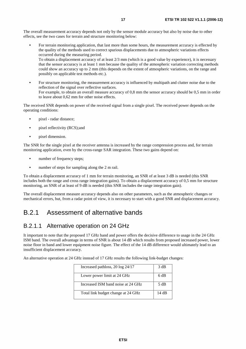
For dynamic monitoring, the measurement is instead performed over a time period of some hours 2 to 6 hours in order to collect enough data for a frequency analysis. For example, monitoring of a bridge dynamic behaviour can be performed by installing the GBSAR system under the bridge, as shown in figure B.3.
Figure B.3: GBSAR system installation for bridge test
ETSI
ETSI TR 102 522 V1.1.1 (2006-12) 19
The GBSAR system allows all the area illuminated by the antenna beamwidth at the same time to be monitored. The resolution of the measurement is equal to the following equation.
Bcresolutionrange 2_ =
where B is the system bandwidth and c is the speed of light.
For a 60 m bridge length (L), using a system bandwidth of 200 MHz, the GBSAR system provides the data on the temporal displacement of about 80 measurement points. To obtain the same set of measurement points using traditional sensor network, the operator would have install 80 sensors (i.e. accelerometers), connected to an acquisition system through at least 100 m cable per sensor.
As depicted in figure B.3, the GBSAR system measures the range displacement of the different range indicators. The real displacement is obtained by projecting the measurement on to the vertical line, from knowledge of the relative position of the GBSAR system with respect to the structure. The measured accuracy of the radial displacement is about 0,1 mm in normal operating condition. The measurement accuracy depends on the accuracy of the knowledge of geometrical characteristics of the installation and on the SNR (Signal to Noise Ratio) of the received signal.
B.3.1.1 Structure monitoring examples
B.3.1.1.1 Static test example
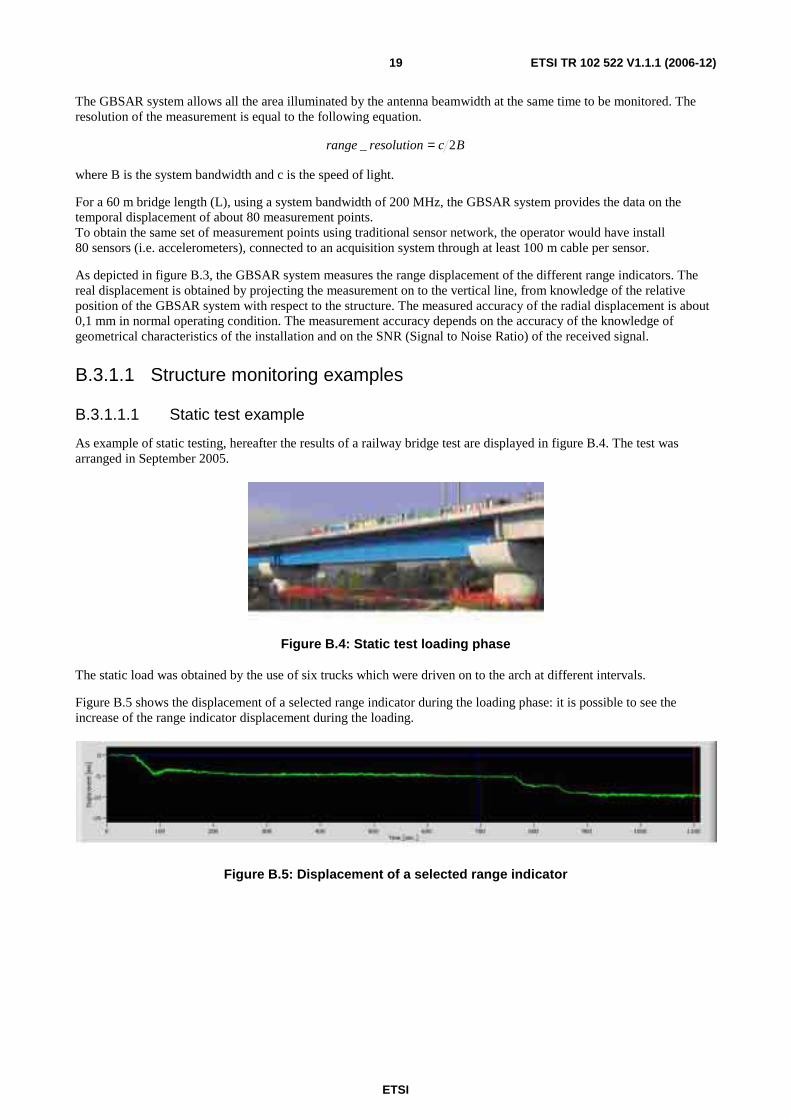
As example of static testing, hereafter the results of a railway bridge test are displayed in figure B.4. The test was arranged in September 2005.
Figure B.4: Static test loading phase
The static load was obtained by the use of six trucks which were driven on to the arch at different intervals.
Figure B.5 shows the displacement of a selected range indicator during the loading phase: it is possible to see the increase of the range indicator displacement during the loading.
Figure B.5: Displacement of a selected range indicator

ETSI
ETSI TR 102 522 V1.1.1 (2006-12) 20
B.3.1.1.2 Dynamic test example
As example of dynamic testing, the results of the Indiano Bridge dynamic test are given. The test was arranged in the year 2004. The bridge is shown in figure B.6 below:
Figure B.6: Bridge view - 206 m length
The GBSAR system was installed under the bridge span, as illustrated in figure B.7 below. The bridge was stressed by the traffic jam.
Figure B.7: Sketch of the system installation
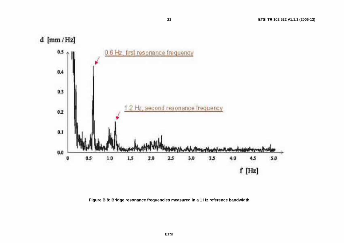
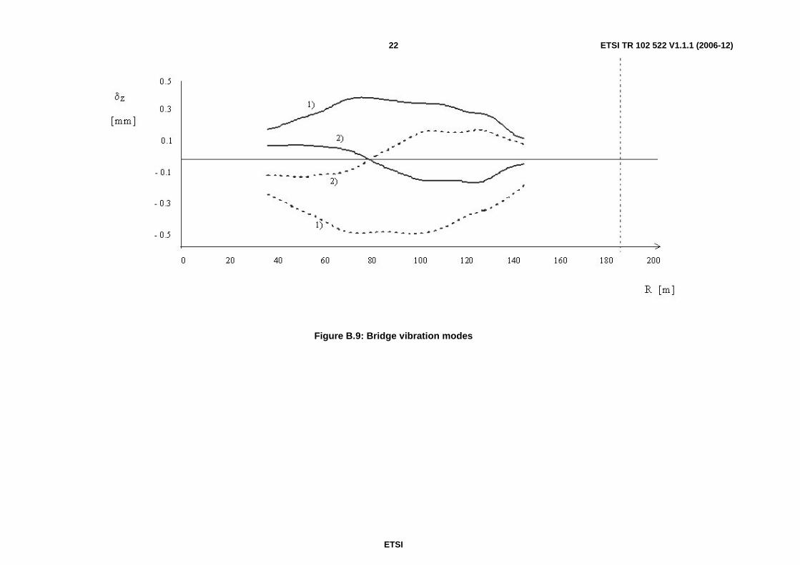
The processing of the data collected by the system has given:
• the resonance frequencies;
• the shape of the vibration modes.
The results are shown in figures B.8 and B.9.
ETSI
ETSI TR 102 522 V1.1.1 (2006-12) 21
Figure B.8: Bridge resonance frequencies measured in a 1 Hz reference bandwidth
ETSI
ETSI TR 102 522 V1.1.1 (2006-12) 22
Figure B.9: Bridge vibration modes
ETSI
ETSI TR 102 522 V1.1.1 (2006-12) 23
B.3.1.2 Terrain monitoring application
Nowadays in order to detect displacements geologists use techniques that need access to the monitored object to install contact sensor networks.
The sensor network provides a set of data relating to the geometrical positions of the sensors installed on the monitored object, losing information on any other part not covered by sensors. At present where global information from a very
large area of interest is needed, it is necessary to exploit satellites present using the space borne SAR monitoring technique, which however has clear limitations for continuous and detailed monitoring of specific areas.
The GBSAR system is able to overcome the problems of access and of the partial lack of information about the monitored area experienced by the physical monitoring techniques, keeping a cost-effective solution. The GBSAR system allows the operator:
• To monitor the unstable slope by installing the system in a remote site, far away from the unsafe landslide (remote sensing).
• To eliminate the need for sensors or reflector on the unstable slope.
• To retrieve displacement data related to the entire illuminated area by the antenna beam width.
These innovative characteristics come with operative conditions that allow a wider and more complete terrain monitoring. The GBSAR system allows the operator:
• To monitor landslides of some km2 dimension, with a displacement accuracy of 1mm.
• To monitor completely unreachable instability slopes, on which it is impossible to install sensors.
• To monitor slopes far away from the installation sites, thanks to the 4 km range of the system.
• To perform a continuous remote unmanned monitoring, the system control can be performed from remote sites using wireless links.
• To monitor different landslides using the same device; current sensor techniques require the installation of new sensor networks for each landslide to be monitored. The ability of reusing the same instrument for different landslides is useful for survey of large areas and is cost-effective.
The monitoring tests last for one or two weeks at the maximum, with the opportunity to return to monitor the same landslide if the speed of the terrain is too slow to be monitored in a single survey.
During a test the transmitting time of the radar is about 10 % to 20 % of the total time survey, depending on the speed of the terrain movement.
ETSI
ETSI TR 102 522 V1.1.1 (2006-12) 24
B.3.1.2.1 Terrain monitoring examples
B.3.1.2.1.1 Tessina landslide measurement survey
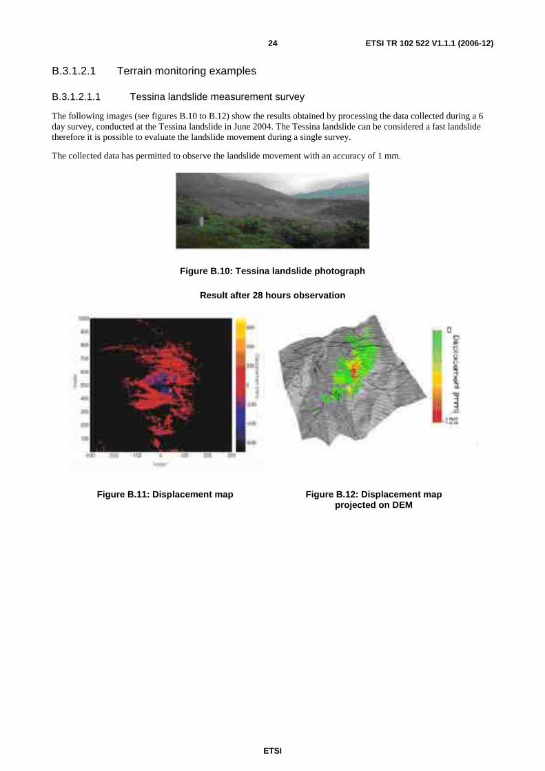
The following images (see figures B.10 to B.12) show the results obtained by processing the data collected during a 6 day survey, conducted at the Tessina landslide in June 2004. The Tessina landslide can be considered a fast landslide therefore it is possible to evaluate the landslide movement during a single survey.
The collected data has permitted to observe the landslide movement with an accuracy of 1 mm.
Figure B.10: Tessina landslide photograph
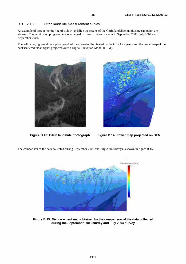
Result after 28 hours observation
Figure B.11: Displacement map Figure B.12: Displacement map projected on DEM
ETSI
ETSI TR 102 522 V1.1.1 (2006-12) 25
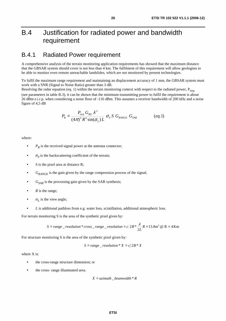
B.3.1.2.1.2 Citrin landslide measurement survey
As example of terrain monitoring of a slow landslide the results of the Citrin landslide monitoring campaign are showed. The monitoring programme was arranged in three different surveys in September 2003, July 2004 and September 2004.
The following figures show a photograph of the scenario illuminated by the GBSAR system and the power map of the backscattered radar signal projected over a Digital Elevation Model (DEM).
Figure B.13: Citrin landslide photograph Figure B.14: Power map projected on DEM
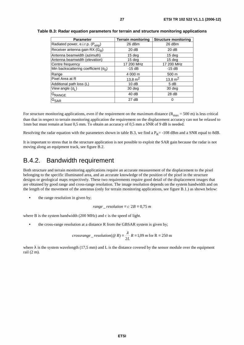
The comparison of the data collected during September 2003 and July 2004 surveys is shown in figure B.15.
Figure B.15: Displacement map obtained by the comparison of the data collected during the September 2003 survey and July 2004 survey
ETSI
ETSI TR 102 522 V1.1.1 (2006-12) 26
B.4 Justification for radiated power and bandwidth requirement
B.4.1 Radiated Power requirement A comprehensive analysis of the terrain monitoring application requirements has showed that the maximum distance that the GBSAR system should cover is not less than 4 km. The fulfilment of this requirement will allow geologists to be able to monitor even remote unreachable landslides, which are not monitored by present technologies.
To fulfil the maximum range requirement and maintaining an displacement accuracy of 1 mm, the GBSAR system must work with a SNR (Signal to Noise Ratio) greater than 3 dB. Resolving the radar equation (eq. 1) within the terrain monitoring context with respect to the radiated power, Peirp
(see parameters in table B.3), it can be shown that the minimum transmitting power to fulfil the requirement is about 26 dBm e.i.r.p. when considering a noise floor of -116 dBm. This assumes a receiver bandwidth of 200 kHz and a noise figure of 4,5 dB
)1.()sin()4( 043
2
eqGGSLR
GPP SARRANGE
L
RXeirpR σ
απλ
=
where:
• PR is the received signal power at the antenna connector;
• σ0 is the backscattering coefficient of the terrain;
• S is the pixel area at distance R;
• GRANGE is the gain given by the range compression process of the signal;
• GSAR is the processing gain given by the SAR synthesis;
• R is the range;
• αL is the view angle;
• L is additional pathloss from e.g. water loss, scintillation, additional atmospheric loss.
For terrain monitoring S is the area of the synthetic pixel given by:
*2__*_ 2 ==== mRL
BcresolutionrangecrossresolutionrangeSλ
For structure monitoring S is the area of the synthetic pixel given by:
XBcXresolutionrangeS *2*_ ==
where X is:
• the cross-range structure dimension; or
• the cross- range illuminated area.
RbeamwidthazimuthX *_=
ETSI
ETSI TR 102 522 V1.1.1 (2006-12) 27
Table B.3: Radar equation parameters for terrain and structure monitoring applications
Parameter Terrain monitoring Structure monitoring Radiated power, e.i.r.p. (Peirp) 26 dBm 26 dBm
Receiver antenna gain RX (GR) 20 dB 20 dB
Antenna beamwidth (azimuth) 15 deg 15 deg Antenna beamwidth (elevation) 15 deg 15 deg Centre frequency 17 200 MHz 17 200 MHz Min backscattering coefficient (σ0) -15 dB -15 dB
Range 4 000 m 500 m Pixel Area at R 13,8 m2 13,8 m2 Additional path loss (L) 10 dB 5 dB View angle (αL) 30 deg 30 deg
GRANGE 40 dB 28 dB
GSAR 27 dB 0
For structure monitoring applications, even if the requirement on the maximum distance (Rmax = 500 m) is less critical than that in respect to terrain monitoring application the requirement on the displacement accuracy can not be relaxed to 1mm but must remain at least 0,5 mm. To obtain an accuracy of 0,5 mm a SNR of 9 dB is needed.
Resolving the radar equation with the parameters shown in table B.3, we find a PR= -108 dBm and a SNR equal to 8dB.
It is important to stress that in the structure application is not possible to exploit the SAR gain because the radar is not moving along an equipment track, see figure B.2.
B.4.2. Bandwidth requirement Both structure and terrain monitoring applications require an accurate measurement of the displacement to the pixel belonging to the specific illuminated area, and an accurate knowledge of the position of the pixel in the structure designs or geological maps respectively. These two requirements require good detail of the displacement images that are obtained by good range and cross-range resolution. The image resolution depends on the system bandwidth and on the length of the movement of the antennas (only for terrain monitoring applications, see figure B.1.) as shown below:
• the range resolution in given by;
mBcresolutionrange 75,02_ ==
where B is the system bandwidth (200 MHz) and c is the speed of light.
• the cross-range resolution at a distance R from the GBSAR system is given by;
m250Rfor 09,12
)(@_ === mRL
Rresolutioncrossrangeλ
where λ is the system wavelength (17,5 mm) and L is the distance covered by the sensor module over the equipment rail (2 m).
ETSI
ETSI TR 102 522 V1.1.1 (2006-12) 28
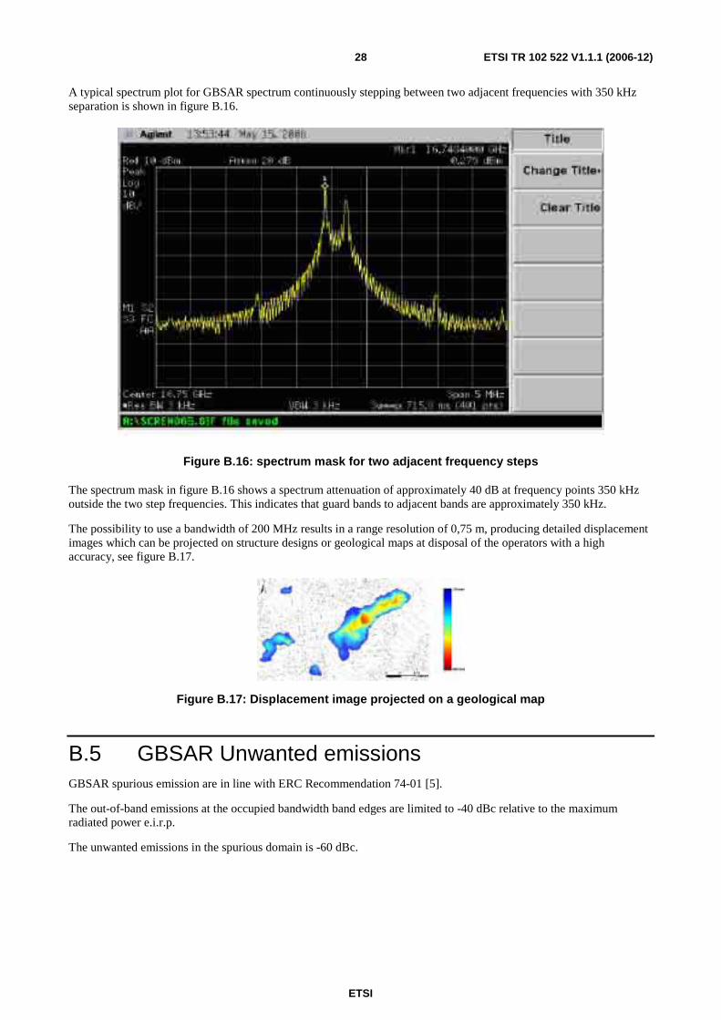
A typical spectrum plot for GBSAR spectrum continuously stepping between two adjacent frequencies with 350 kHz separation is shown in figure B.16.
Figure B.16: spectrum mask for two adjacent frequency steps
The spectrum mask in figure B.16 shows a spectrum attenuation of approximately 40 dB at frequency points 350 kHz outside the two step frequencies. This indicates that guard bands to adjacent bands are approximately 350 kHz.
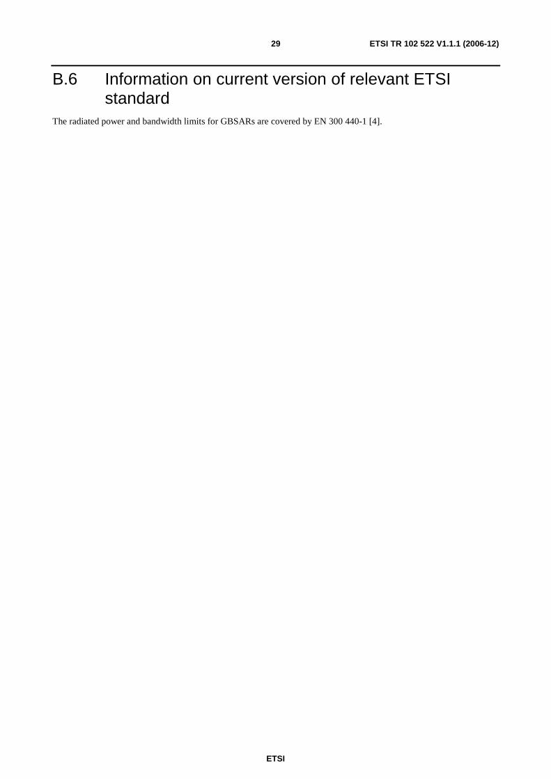
The possibility to use a bandwidth of 200 MHz results in a range resolution of 0,75 m, producing detailed displacement images which can be projected on structure designs or geological maps at disposal of the operators with a high accuracy, see figure B.17.
Figure B.17: Displacement image projected on a geological map
B.5 GBSAR Unwanted emissions GBSAR spurious emission are in line with ERC Recommendation 74-01 [5].
The out-of-band emissions at the occupied bandwidth band edges are limited to -40 dBc relative to the maximum radiated power e.i.r.p.
The unwanted emissions in the spurious domain is -60 dBc.
ETSI
ETSI TR 102 522 V1.1.1 (2006-12) 29
B.6 Information on current version of relevant ETSI standard
The radiated power and bandwidth limits for GBSARs are covered by EN 300 440-1 [4].
ETSI
ETSI TR 102 522 V1.1.1 (2006-12) 30
Annex C: Expected compatibility issues
C.1 Coexistence issues The unit density of GBSAR is expected to be very low. The numbers of GBSAR units are not expected to proliferate to the point where aggregation could affect any of the primary services in the proposed frequency band of operation.
It is not expected to have difficulties in adjacent bands. An appropriate guard band may be added by considering the equipment spectrum mask, see figure B.16.
The SF-CW modulation over a frequency range of up to 200 MHz also offers potential to be used as mitigation factor.
C.2 Current ITU allocations The current ITU allocations for the proposed spectrum for GBSAR applications are shown in table C.2.1.
Table C.2.1: ITU allocations for proposed GBSAR frequencies
Frequency band ITU allocations 17,1 GHz to 17,2 GHz Radiolocation Service
Mobile Services 17,2 GHz to 17,3 GHz Earth Exploration Satellite Service (active)
Mobile Service Radio Location Service Space Research (active)
C.3 Sharing issues Applicable studies to be decided by ECC.
ETSI
ETSI TR 102 522 V1.1.1 (2006-12) 31
History
Document history
V1.1.1 December 2006 Publication


![TR 102 491 - V1.2.1 - Electromagnetic compatibility and ... · (IPI)". [13] ERC/DEC ... AGA Air Ground Air ... ERM ETSI Electromagnetic compatibility and Radio spectrum Matters GoS](https://img.pdfslide.net/doc/110x75/5b0111ee7f8b9ad85d8d8b4d/tr-102-491-v121-electromagnetic-compatibility-and-ipi-13-ercdec-.jpg)