Embed Size (px)
Citation preview

ETSI TR 102 644-2 V1.1.1 (2009-03)
Technical Report
Electromagnetic compatibilityand Radio spectrum Matters (ERM);
RFID Plugtests to investigate the interoperability of tagsmanufactured by different vendors;
Part 2: Test plan and preliminary tests

ETSI
ETSI TR 102 644-2 V1.1.1 (2009-03)2
Reference DTR/ERM-TG34-006-2
Keywords SRD, radio, testing
ETSI
650 Route des Lucioles F-06921 Sophia Antipolis Cedex - FRANCE
Tel.: +33 4 92 94 42 00 Fax: +33 4 93 65 47 16
Siret N° 348 623 562 00017 - NAF 742 C
Association à but non lucratif enregistrée à la Sous-Préfecture de Grasse (06) N° 7803/88
Important notice
Individual copies of the present document can be downloaded from: http://www.etsi.org
The present document may be made available in more than one electronic version or in print. In any case of existing or perceived difference in contents between such versions, the reference version is the Portable Document Format (PDF).
In case of dispute, the reference shall be the printing on ETSI printers of the PDF version kept on a specific network drive within ETSI Secretariat.
Users of the present document should be aware that the document may be subject to revision or change of status. Information on the current status of this and other ETSI documents is available at
http://portal.etsi.org/tb/status/status.asp
If you find errors in the present document, please send your comment to one of the following services: http://portal.etsi.org/chaircor/ETSI_support.asp
Copyright Notification
No part may be reproduced except as authorized by written permission. The copyright and the foregoing restriction extend to reproduction in all media.
© European Telecommunications Standards Institute 2009.
All rights reserved.
DECTTM, PLUGTESTSTM, UMTSTM, TIPHONTM, the TIPHON logo and the ETSI logo are Trade Marks of ETSI registered for the benefit of its Members.
3GPPTM is a Trade Mark of ETSI registered for the benefit of its Members and of the 3GPP Organizational Partners. LTE™ is a Trade Mark of ETSI currently being registered
for the benefit of its Members and of the 3GPP Organizational Partners. GSM® and the GSM logo are Trade Marks registered and owned by the GSM Association.
ETSI
ETSI TR 102 644-2 V1.1.1 (2009-03)3
Contents
Intellectual Property Rights ................................................................................................................................ 5
Foreword ............................................................................................................................................................. 5
Introduction ........................................................................................................................................................ 5
1 Scope ........................................................................................................................................................ 6
2 References ................................................................................................................................................ 6
2.1 Normative references ......................................................................................................................................... 6
2.2 Informative references ........................................................................................................................................ 6
3 Abbreviations ........................................................................................................................................... 7
4 Influences On Tag Interoperability .......................................................................................................... 7
4.1 Preface ................................................................................................................................................................ 7
4.2 Application Scenario .......................................................................................................................................... 7
4.3 Protocol Parameters ............................................................................................................................................ 8
4.4 Individual Tag Characteristics ............................................................................................................................ 9
5 Definition of Tag Interoperability Tests ................................................................................................. 10
6 Tag interoperability tests executed in application scenarios (RFID Plugtests) ...................................... 11
6.1 Introduction ...................................................................................................................................................... 11
6.2 Purpose ............................................................................................................................................................. 11
6.3 Arrangements ................................................................................................................................................... 11
6.4 Test Site ............................................................................................................................................................ 12
6.5 Supervisors ....................................................................................................................................................... 12
6.6 Confidentiality .................................................................................................................................................. 12
6.7 Sponsors ........................................................................................................................................................... 12
6.8 Conduct of Tests ............................................................................................................................................... 13
6.9 Preparations ...................................................................................................................................................... 13
6.10 Applications and Tests ..................................................................................................................................... 13
6.10.1 Application Set-up 1: Portal - Moving Pallet .............................................................................................. 13
6.10.1.1 Application Overview and Purpose ....................................................................................................... 13
6.10.1.2 Application Set-up ................................................................................................................................ 13
6.10.1.3 Test Preparation .................................................................................................................................... 14
6.10.1.4 Test Procedure ....................................................................................................................................... 15
6.10.2 Application Set-up 2: Conveyor - Moving Case ......................................................................................... 16
6.10.2.1 Application Overview and Purpose ....................................................................................................... 16
6.10.2.2 Application Set-up ................................................................................................................................ 16
6.10.2.3 Test Preparation .................................................................................................................................... 17
6.10.2.4 Test Procedure ....................................................................................................................................... 18
6.10.3 Application Set-up 3: Rack of DVDs - Shelf Reader ................................................................................. 18
6.10.3.1 Application Overview and Purpose ....................................................................................................... 18
6.10.3.2 Application Set-up ................................................................................................................................ 18
6.10.3.3 Test Preparation .................................................................................................................................... 19
6.10.3.4 Test Procedure ....................................................................................................................................... 20
6.10.4 Application Set-up 4: Retail Store - Handheld Reader ............................................................................... 21
6.10.4.1 Application Overview and Purpose ....................................................................................................... 21
6.10.4.2 Application Set-up ................................................................................................................................ 21
6.10.4.3 Test Preparation .................................................................................................................................... 22
6.10.4.4 Test Procedure ....................................................................................................................................... 23
6.11 Result Logging and Evaluation ........................................................................................................................ 24
6.11.1 Final Report ................................................................................................................................................ 24
6.11.2 Real Time Result Evaluation (Local Result Monitoring Screens) .............................................................. 24
6.11.3 Result Database .......................................................................................................................................... 24
6.11.4 noFillis CrossTalk Platform ........................................................................................................................ 25
6.11.5 Reader Log Files ......................................................................................................................................... 26

ETSI
ETSI TR 102 644-2 V1.1.1 (2009-03)4
7 Reader independent Tag Interoperability Tests (Preliminary TESTS) .................................................. 26
7.1 Introduction ...................................................................................................................................................... 26
7.2 ASIC Specific Tests ......................................................................................................................................... 26
7.2.1 General ........................................................................................................................................................ 26
7.2.2 Goal ............................................................................................................................................................ 26
7.2.3 Tag ASICs under Test................................................................................................................................. 26
7.2.4 Test Setup ................................................................................................................................................... 27
7.2.5 Metrics ........................................................................................................................................................ 30
7.2.6 Test Method ................................................................................................................................................ 30
7.2.7 Control Reader Configurations (Test Cases) .............................................................................................. 31
7.3 Tag Specific Tests ............................................................................................................................................ 32
7.3.1 General ........................................................................................................................................................ 32
7.3.2 Goal ............................................................................................................................................................ 32
7.3.3 Tags under Test ........................................................................................................................................... 32
7.3.4 Test Setup ................................................................................................................................................... 33
7.3.5 Test Method ................................................................................................................................................ 34
Annex A: Bibliography .......................................................................................................................... 36
History .............................................................................................................................................................. 37

ETSI
ETSI TR 102 644-2 V1.1.1 (2009-03)5
Intellectual Property Rights IPRs essential or potentially essential to the present document may have been declared to ETSI. The information pertaining to these essential IPRs, if any, is publicly available for ETSI members and non-members, and can be found in ETSI SR 000 314: "Intellectual Property Rights (IPRs); Essential, or potentially Essential, IPRs notified to ETSI in respect of ETSI standards", which is available from the ETSI Secretariat. Latest updates are available on the ETSI Web server (http://webapp.etsi.org/IPR/home.asp).
Pursuant to the ETSI IPR Policy, no investigation, including IPR searches, has been carried out by ETSI. No guarantee can be given as to the existence of other IPRs not referenced in ETSI SR 000 314 (or the updates on the ETSI Web server) which are, or may be, or may become, essential to the present document.
Foreword This Technical Report (TR) has been produced by ETSI Technical Committee Electromagnetic compatibility and Radio spectrum Matters (ERM).
The present document is part 2 of a multipart deliverable covering RFID Plugtest that was performed at the MGI centre in Neuss and at the VanDerLande premises in Veghel during the period 11th - 15th June 2008.
Part 1: "RFID Plugtests report";
Part 2: "Test plan and preliminary tests".
Introduction Different applications, like conveyor belts or dock door portals, are characterized by different properties such as field characteristics, tag population, speed and tag/reader density. These properties impose different requirements such as read or write sensitivity and resistance to mutual coupling. When exposing tags of various types from different vendors to application specific conditions, some tags might influence the operability of others, thereby being mutually incompatible.
The goal of tag interoperability tests is to investigate issues of potential incompatibility that arise due to the use of tags of various types from different vendors in application specific conditions.
The result is the test report made publicly available via the ETSI web-page. Prior to the RFID Plugtests, preliminary tests were conducted using a well documented, dedicated test reader with one antenna port and special measurement equipment for extended evaluation options (referred to as the control reader). In order to gain the best understanding of possible anomalies these preliminary tests were conducted using two different set-ups. The ASIC specific test set-up focused on the inventory of multiple tags hard wired to the control reader, (i.e. eliminating the influences of the RF field). The tag specific test set-up focused on the inventory of multiple tags under application specific conditions (using an antenna to generate a RF field instead of hard wiring the tags to the control reader).
In the second step the ETSI RFID Plugtests were executed in application scenarios using commercially available equipment. As the results of the preliminary tests merely provide a basis for understanding potential issues, only the results of the ETSI RFID Plugtests are included in Part 1 of TR 102 644 [i.6].

ETSI
ETSI TR 102 644-2 V1.1.1 (2009-03)6
1 Scope The present document defines a test plan for tag interoperability tests. The main objective of such tests is to confirm that mixed populations of tags (tags of different types and/or from different vendors) can be identified correctly. The tests are defined in a two-step approach.
The present document identifies the main factors influencing tag interoperability including application scenarios, protocol parameters and individual tag characteristics. Each of these aspects is addressed in detail with the aim of providing a test plan and evaluation matrices for tag interoperability tests. Protocol specific issues in the present document are focused on the EPCglobal Class 1 Generation 2 (C1G2) air interface specification [i.2] and the air interface specification ISO/IEC 18000-6 Type C [i.3].
The present document served as basis for carrying out ETSI Plugtests (RFID Interoperability Event) in June 2008.
2 References References are either specific (identified by date of publication and/or edition number or version number) or non-specific.
• For a specific reference, subsequent revisions do not apply.
• Non-specific reference may be made only to a complete document or a part thereof and only in the following cases:
- if it is accepted that it will be possible to use all future changes of the referenced document for the purposes of the referring document;
- for informative references.
Referenced documents which are not found to be publicly available in the expected location might be found at http://docbox.etsi.org/Reference.
NOTE: While any hyperlinks included in this clause were valid at the time of publication ETSI cannot guarantee their long term validity.
2.1 Normative references The following referenced documents are indispensable for the application of the present document. For dated references, only the edition cited applies. For non-specific references, the latest edition of the referenced document (including any amendments) applies.
Not applicable.
2.2 Informative references The following referenced documents are not essential to the use of the present document but they assist the user with regard to a particular subject area. For non-specific references, the latest version of the referenced document (including any amendments) applies.
[i.1] ETSI TS 102 237-1: "Telecommunications and Internet Protocol Harmonization Over Networks (TIPHON) Release 4; Interoperability test methods and approaches; Part 1: Generic approach to interoperability testing".
[i.2] EPCglobal: "EPCTM Radio-Frequency Identity Protocols; Class-1 Generation-2 UHF RFID; Protocol for Communications at 860 MHz - 960 MHz", Version 1.1.0.
NOTE: Available at http://www.epcglobalinc.org/standards/uhfc1g2/uhfc1g2_1_1_0-standard-20071017.pdf.

ETSI
ETSI TR 102 644-2 V1.1.1 (2009-03)7
[i.3] ISO/IEC 18000-6: "Information technology - Radio frequency identification for item management - Part 6: Parameters for air interface communications at 860 MHz to 960 MHz".
[i.4] Void.
[i.5] ETSI EN 302 208-1 (V1.2.1): "Electromagnetic compatibility and Radio spectrum Matters (ERM); Radio Frequency Identification Equipment operating in the band 865 MHz to 868 MHz with power levels up to 2 W; Part 1: Technical requirements and methods of measurement".
[i.6] ETSI TR 102 644-1: "Electromagnetic compatibility and Radio spectrum Matters (ERM); RFID Plugtests to investigate the interoperability of tags manufactured by different vendors; Part 1: RFID Plugtests report".
[i.7] CEPT/ERC REC 70-03: Relating to the use of Short Range Devices (SRD).
3 Abbreviations For the purposes of the present document, the following abbreviations apply:
ASIC Application Specific Integrated Circuit EUT Equipment Under Test RFID Radio Frequency IDentification QE Qualified Equipment
4 Influences On Tag Interoperability
4.1 Preface The main factors influencing tag interoperability are the application scenario, protocol parameters, and individual tag characteristics. Each of these factors is addressed in detail in the following clauses. However due to the large number of variables associated with application scenarios and protocol parameters, it is only possible to cover the main factors influencing tag behaviour. Since there could be issues in assigning interrogator related characteristics either to the application scenario or to the protocol parameters, the following convention is adopted: software definable characteristics are assigned to the protocol parameters while all others are assigned to the application scenario.
4.2 Application Scenario The application scenario describes the set-up in which an RFID interrogator and tags are used. The main characteristics of an application scenario include:
• Environment:
- All aspects that have a certain influence on an application but are not part of the application itself (like surrounding material, noise sources of any kind e.g. mobile phones).
• Reader antenna arrangement:
- Position and orientation of the reader antennas in a set-up.
- Number of reader antennas.
- Type of reader antennas.
• Tag arrangement:
- Position and orientation of the tags in a set-up.
- Number of tags.

ETSI
ETSI TR 102 644-2 V1.1.1 (2009-03)8
- Type of tags (different vendors/models).
• Relative movement between reader antennas and tags:
- Speed.
- Path:
� E.g. pallet moving through portal (tags moving).
� E.g. handheld reader (reader antenna moving).
• Pallet / Case / Item characteristics:
- Materials.
- Arrangement.
4.3 Protocol Parameters The protocol parameters describe the protocol settings, as well as other software options associated with a particular application set-up. The main protocol parameters are (C1G2 specific where applicable):
• Link rates:
- Forward link.
- Return link.
• Modulation/Encoding:
- Modulation type (forward link).
- Modulation depth (forward link).
- Duty cycle (forward link).
- Encoding (return link).
• CW:
- Power.
- Frequency.
• Link timing:
- In most cases not selectable!
• Protocol flow:
- Command sequence.
- Collision-arbitration concept (Q protocol).
- Function:
� Selection/inventory only.
� Access - write.
• Session usage:
- Session flag.
- Selected flag.

ETSI
ETSI TR 102 644-2 V1.1.1 (2009-03)9
- A � B, B � A inventory.
• TRext usage:
- Pilot tone.
- No pilot tone.
• Reader antenna switching:
- Sequence.
- Timing.
- Interrelation with protocol concepts (e.g. inventory round).
4.4 Individual Tag Characteristics The individual tag characteristics describe attributes that, due to variations between different tags, may influence tag interoperability. Some of these attributes are defined for the RFID Plugtests and assume tags operating under ISO/IEC 18000-6 [i.3].
• Read range:
- The sensitivity of a tag typically expressed as forward link range for a given transmit level.
• Orientation tolerance:
- The sensitivity of a tag in terms of its read range if it is rotated away from its preferred orientation.
• Frequency tolerance:
- The sensitivity of a tag in terms of its read range at various carrier frequencies from 860 MHz to 960 MHz.
- Tags with high frequency tolerance typically show less variation in sensitivity if attached to different materials.
• Interference tolerance:
- Describes the degradation in read range of tags from interference generated by other nearby interrogators (e.g. dense interrogator environment).
• Backscatter range:
- The strength of a backscatter response from a tag for a given downlink field level in terms of return link range.
- The range of the return link for passive tags typically is greater than the range of the forward link.
- The efficiency of the hardware design for generating the backscatter signal.
• Backscatter timing:
- The interval between the instant that the interrogator ceases transmitting its modulated signal and the instant that the tag starts to transmit its backscatter response.
• Write range:
- The write sensitivity of the tag, i.e. the maximum forward link range at which it is possible to write data into a tag.
• Write time:
- The time taken to write x bits into a tag.
ETSI
ETSI TR 102 644-2 V1.1.1 (2009-03)10
• Tag proximity:
- Describes the degradation in read range of a tag when positioned in proximity to another tag / other tags.
- Detuning immunity.
- Mutual coupling.
• Tag flags persistence time:
- Persistence time of the S1, S2, S3 and SL flags.
• Tag RNG probability:
- Probability of a tag's RNG to roll a 1 in a specific time slot.
5 Definition of Tag Interoperability Tests Tag Interoperability Test: ETSI defines interoperability as the "ability of two systems to interoperate using the same communication protocol" ([i.1], p.8). Furthermore, the purpose of interoperability testing is identified as to "prove that end-to-end functionality between (at least) two communicating systems is as required by the standard(s) on which those systems are based" ([i.1], p.9). ETSI clearly highlights that each interoperability test configuration includes one, and only one, subject of test called the Equipment Under Test (EUT) ([i.1], p.13).
For the purposes of the RFID Plugtests tag interoperability is defined as the ability of an RFID interrogator (Qualified Equipment - QE) to interoperate with a population of RFID tags (Equipment Under Test EUT) using the same communication protocol, wheras.
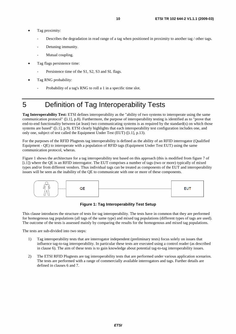
Figure 1 shows the architecture for a tag interoperability test based on this approach (this is modified from figure 7 of [i.1]) where the QE is an RFID interrogator. The EUT comprises a number of tags (two or more) typically of mixed types and/or from different vendors. Thus individual tags can be treated as components of the EUT and interoperability issues will be seen as the inability of the QE to communicate with one or more of these components.
Figure 1: Tag Interoperability Test Setup
This clause introduces the structure of tests for tag interoperability. The tests have in common that they are performed for homogenous tag populations (all tags of the same type) and mixed tag populations (different types of tags are used). The outcome of the tests is assessed mainly by comparing the results for the homogenous and mixed tag populations.
The tests are sub-divided into two steps:
1) Tag interoperability tests that are interrogator independent (preliminary tests) focus solely on issues that influence tag-to-tag interoperability. In particular these tests are executed using a control reader (as described in clause 6). The aim of these tests is to gain knowledge about potential tag-to-tag interoperability issues.
2) The ETSI RFID Plugtests are tag interoperability tests that are performed under various application scenarios. The tests are performed with a range of commercially available interrogators and tags. Further details are defined in clauses 6 and 7.

ETSI
ETSI TR 102 644-2 V1.1.1 (2009-03)11
6 Tag interoperability tests executed in application scenarios (RFID Plugtests)
6.1 Introduction This clause defines tag interoperability tests that are performed in a series of real life scenarios, which are representative of applications in the logistics and retail industries. The tests include the movement of tagged cartons on pallets moving through dock doors and the movement of tagged objects on conveyors. In addition tests use both shelf readers and hand held readers. For the tests commercially available interrogators and tags are used.
The tests were carried out at an ETSI Plugtests event (RFID Interoperability Event), which took place from 11th to 15th June 2008 at the Metro Group - RFID Innovation Center in Neuss (Germany) and at VanDerLande Industries in Veghel (The Netherlands).
Details are discussed below.
6.2 Purpose The purpose of the Plugtests described herein is to investigate if there is a satisfactory level of interoperability between RFID equipment (interrogators and tags) supplied by different vendors. The main objective of the tag interoperability tests is to confirm that mixed populations of tags (tags of different types and/or from different vendors) can be identified correctly by interrogators provided by different manufacturers. This information is of major strategic importance to those end-users who wish to use RFID on a global basis.
The results from the Plugtests is published in TR 102 644-1[i.6], which is documented in a way that avoids disclosure of the performance of individual manufacturer's equipment (tags and interrogators).
6.3 Arrangements The Plugtests took place from 11-15 June 2008. The deadline for registration was 22 May 2008. In order to ease logistics it was recommended that participants ship equipment in advance with a shipment deadline of 27 May 2008.
To allow adequate time for preparation of the test set-ups, tags were provided well in advance with a shipment deadline of 20 May 2008. Details about the preparations for individual tests are covered further below in this clause.
The following days were allocated for carrying out tests:
• Wednesday, 11 June 2008:
- Application Set-up 3: Rack of DVDs - Shelf Reader.
- Application Set-up 4: Retail Store - Handheld Reader.
• Thursday, 12 June 2008:
- Application Set-up 1: Portal - Moving Pallet.
• Friday, 13 June 2008:
- Application Set-up 2: Conveyor - Moving Case.
The other days were left open in order to allow for investigation of unresolved issues, repetition of individual tests, review of results, and any other business.
Tests commenced at 9 a.m. at each of the test days.
Participating tag and ASIC manufacturers were each requested to provide at least 1 000 tags for the Plugtests. The tags were programmed by Metro during test preparation.

ETSI
ETSI TR 102 644-2 V1.1.1 (2009-03)12
Reader manufacturers were invited to provide interrogators optimized for each of the four applications mentioned above (since the tests did not take place in parallel but on separate days, the same interrogators may have been reused for different applications). The interrogators used in application setups 1 to 3 were fitted with four SMA female connectors for connection to the feeder cables from the antennas at the application set-ups. For interrogators used in application setup 4 (handheld readers) a specification of the built-in antenna (e.g. radiation pattern) were provided as a reference.
All interrogators conformed to the technical requirements of EN 302 208-1 [i.5]. Manufacturers supplied suitable software and any specialist hardware necessary to drive the interrogators and to display the results.
In order to simplify logging of the results and real time analysis, it was desirable that interrogators provide an interface to the data logging platform, which was used at the test site. For those interrogators that did not support the CrossTalk platform, the results were fed manually into the evaluation system. In this case reader manufacturers were required to provide example log files in advance (deadline 27 May 2008). For detailed information about the evaluation system and processing of the results please see further below.
An interface validation point was made available at the test site in order to allow reader vendors to verify their interface to the evaluation system prior to the commencement of the tests.
Mains power points with 230 V at 50 Hz were provided at the test site.
6.4 Test Site The Plugtests mainly took place at the Metro Group - RFID Innovation Center in Neuss (Germany). The address is:
METRO Group - RFID Innovation Center Mainstraße 113-119 (access via Kruppstrasse) 41469 Neuss - GERMANY Tel: +49 (0)2 11 96 95 936 Fax: +49 (0)21 37 92 78 44
The tests for Application Setup 2 (Conveyor - Moving Case) were carried out at VanDerLande Industries in Veghel (The Netherlands) on Friday, 13 June 2008. A coach carried the participants and equipment from Düsseldorf (Nikko hotel) to Veghel (test site) on Friday morning and back on Friday evening. The address was:
Vanderlande Industries Nederland B.V. (Headquarters) Vanderlandelaan 2 5466 RB Veghel Phone: +31 (0)413 38 55 15 Fax: +31 (0)413 38 50 25
Details to follow (floor plans).
6.5 Supervisors The Plugtests was managed by four neutral test supervisors. These were John Falck (Chairman ERM_TG34), EPCglobal Inc. (to be confirmed), Josef Preishuber-Pfluegl and Manfred Jantscher (both CISC Semiconductor Design+Consulting GmbH). All test supervisors signed the ETSI NDA and treated the results from each manufacturer's equipment in the strictest confidence.
6.6 Confidentiality As a precondition of participating in the RFID Plugtests, all participants were required to sign the ETSI NDA. Any information of a confidential nature that participants may have acquired during the course of the RFID Plugtests relating to other participants and their equipment was agreed to only be used only for the purpose of these Plugtests and not be divulged to any person not present at the Plugtests without the written agreement of the owner of the confidential information.
6.7 Sponsors The Plugtests were sponsored by the Information Society of the European Commission.

ETSI
ETSI TR 102 644-2 V1.1.1 (2009-03)13
6.8 Conduct of Tests The individual application tests were conducted according to the guidelines provided in clause 6.11. The representatives from each manufacturer assisted the test supervisors in the conduct of the tests. However only test supervisors were permitted to record test results. The results of the tests were recorded according to the guidelines in clause 6.11. The recorded results were not directly traceable to individual manufacturers.
6.9 Preparations Metro provided means to conduct tests for application Set-ups 1, 3 and 4. VanDerLande Industries provided means to conduct tests for application Set-up 2.
6.10 Applications and Tests This clause discusses details about the individual test application set-ups. It covers the description of the set-ups including the purposes of the tests, guidelines for preparations, and guidelines for conducting the tests.
6.10.1 Application Set-up 1: Portal - Moving Pallet
6.10.1.1 Application Overview and Purpose
Portal set-ups, like dock door portals, are very common in the supply chain. Typically, a number of tagged cases/items placed on a tagged pallet are moved through a portal with the aim to inventory the pallet, case, and item tags.
The purpose of the tests described in this clause is to verify that there is a satisfactory level of interoperability between tags and interrogators supplied by different vendors when used in a typical portal scenario.
In the tests, pallets of tagged cartons (homogenous and mixed tag populations) were moved through a portal by a battery powered pallet truck. The tags were identified by the interrogator connected to the portal antennas.
6.10.1.2 Application Set-up
The test application set-up basically comprises a portal fitted with four antennas, an interrogator connected to these antennas, a pallet of tagged cartons, and a battery powered pallet truck.
The portal including the antennas were made available by Metro. The interrogators were provided by the participating reader vendors (one per vendor). The tags were provided by the participating tag vendors. The pallet set-up were prepared in advance by Metro.
There were several pallets with different tag populations. With the exception that different tag types were attached to the cartons, all pallets were identical. The cartons included material that influences the readability of RFID tags (e.g. detergent). Details are discussed in further below.
Table 1 summarizes the application parameters for the portal application set-up. Table 2 summarizes the corresponding protocol parameters.

ETSI
ETSI TR 102 644-2 V1.1.1 (2009-03)14
Table 1: AS1 - Application Parameters
Parameter Description Remark Environment Representative of a distribution centre
Dock door portals There might be several portals used for testing in parallel (avoid influences from adjacent portals - sufficient distance; minimize number of variables in tests!)
Antenna arrangement Typical dock door portal 4 antennas (2 left, 2 right) connected to a single interrogator Circularly polarized antennas
Interrogators provided by different vendors were connected to the antennas
Tag arrangement Tags attached to cartons Cartons arranged on pallet Placement of tags on cartons and arrangement of cartons on pallet optimized as in real application set-up (Metro know-how)
Several pallets with different tag populations were prepared in advance
Movement Battery powered pallet truck used at full speed to move pallet through portal Straight movement path
Light curtain was used to start interrogator operation Interrogator inventoried for 2 s
Case characteristics All cartons were identical in order to minimize number of variables Cartons included material that influences readability of tags (e.g. detergent)
Table 2: AS1 - Protocol Parameters
Parameter Value Remark Data rates, modulation, encoding Defined by reader vendor DRM (Miller sub carrier encoding) was
required CW power, CW frequency, channel sharing technique
Defined by reader vendor ERC Rec 70-03 [i.7], annex 11 Requirements of EN 302 208-1 [i.5] were met
Protocol flow, session usage, TRext usage, antenna switching, other (like Q parameter settings)
Defined by reader vendor Reader vendors were allowed to optimize their interrogator for application set-up
NOTE: Reader vendors were required to provide test supervisors with written details of the specific configuration parameters used during the tests.
6.10.1.3 Test Preparation
Portals: Provided by Metro. It was anticipated that two or three portals would be available in order to run the tests in parallel. There was sufficient separation between the portals used for the tests to minimize interference. The portals were equipped with a light curtain or similar to indicate the approach of a pallet and provide an output by means of a set of "dry" contacts for connection to an interrogator. Specification of portals including antennas were provided by Metro.
Pallets: Provided by Metro. The pallets for testing were prepared prior to the tests. With the exception that different tags were attached to the cartons, all pallets were identical. The pallets carried a number of tagged cartons (at least 50). All cartons were identical and included material that influences the readability of tags (e.g. detergent). The placement of tags on cartons and arrangement of cartons on pallet was optimized (Metro know-how).

ETSI
ETSI TR 102 644-2 V1.1.1 (2009-03)15
Pallets with homogenous tag populations (tags of same type and from same vendor) and pallets with mixed tag populations (tags of different types and/or from different vendors) were prepared in the following way:
• There was a pallet with a homogenous tag population for each tag type provided for testing:
- The number of pallets with a homogenous tag population depended on the actual number of different tag types available for the tests. As an example for three different tag types A, B, and C there were the following homogenous tag population pallets:
� Pallet with only type A.
� Pallet with only type B.
� Pallet with only type C.
• There were pallets with mixed tag populations. Tags of different types were distributed equally on the pallet:
- The number of pallets with mixed tag populations depended on the number of different tag types available for the tests. As an example for three different tag types A, B, and C there might have been the following pallets with mixed tag population (the number of tags of each type on a pallet should be the same):
� Pallet with all three types A, B, and C.
� Pallet with types A and B only.
� Pallet with types A and C only.
� Pallet with types B and C only.
- There might also have been pallets with a known imbalance in the number of tags of different types:
� e.g. pallet with 95 % tags of type A and only 5 % tags of type B.
• A complete set of pallets (homogenous and mixed tag population types) was provided for each portal used for the tests.
A number of tagged cartons (at least 5 per tag type) was prepared separately in order to allow for unplanned additional tests.
As soon as the actual number of participating tag vendors (number of different tag types) was known, a detailed plan of the test pallets including the arrangement of cartons, placement of tags, types of tags, and EPCs of tags was provided by Metro. A number was assigned to each pallet, which was made visible on the pallet and used for evaluation of the results.
Information about the test pallets was fed into the database of the evaluation system prior to the tests. This included the EPCs of the individual tags and their association with the test pallets (pallet number).
6.10.1.4 Test Procedure
The following steps describe the test procedure used.
1) The interrogator under test was connected to the four antennas mounted at the portal using the SMA connectors/cables.
2) The interrogator under was connected test to the light curtain or similar used to indicate the approach of a pallet.
3) The interface between the interrogator under test and the evaluation system was configured according to the guidelines in clause 6.11.4. If no direct link to the evaluation system was available, the interrogator was configured to generate log files according to the guidelines in clause 6.11.5 (the same format as the sample log file that was provided prior to the tests).
4) The interrogator was configured under test for optimized operation in the portal application consistent with the technical requirements of EN 302 208-1 [i.5].

ETSI
ETSI TR 102 644-2 V1.1.1 (2009-03)16
5) The battery powered pallet truck was prepared with a pallet under test for moving through the portal.
6) For evaluation of the results, the application set-up (portal), the actual portal used for the test (portal number), the interrogator under test (anonymized), the pallet used for the test (pallet number), and the test run number were recorded. It was hoped to support this process by the use of a graphical user interface on a local monitor. If log files were generated, the required data was recorded and linked manually during parsing of the log files into the evaluation system.
7) The pallet was moved through the gate at full speed using the battery powered pallet truck:
a) The interrogator started its operation when triggered by the light curtain or similar.
b) The interrogator stopped inventory 2 s after starting.
c) Each tag inventory was recorded including timestamp, EPC, antenna number, and RSSI value.
8) Steps 6 and 7 were repeated three times (three test runs).
9) Steps 5 to 8 were repeated for each of the prepared pallets.
10) Steps 1 to 9 were repeated for each interrogator under test.
6.10.2 Application Set-up 2: Conveyor - Moving Case
6.10.2.1 Application Overview and Purpose
In typical conveyor belt applications (e.g. logistics, baggage handling) tagged cases, including mixed items, (materials) move sequentially past interrogators with the aim to inventory the tagged objects.
The purpose of the tests described in this clause is to verify that there is a satisfactory level of interoperability between tags and interrogators supplied by different vendors when used in typical conveyor scenarios.
In the tests, tagged cases (e.g. suitcases, cartons) (one tag per case) filled with mixed items (materials) were moved past two reading points (antenna arrangements) mounted on opposite sides of a circular conveyor belt. The tags were identified by interrogators connected to the antenna arrangements. The two reading points differed in their antenna set-ups. One used a flat antenna mounted under the conveyor belt (scanology antenna). The other was equipped with "side antennas" mounted on the left and right sides of the conveyor belt.
6.10.2.2 Application Set-up
The test application set-up basically comprised a circular conveyor belt, a flat antenna mounted under the conveyor belt (scanology antenna) on one side of the conveyor belt, "side antennas" mounted on the left and right sides of the conveyor on the opposite side of the conveyor belt, interrogators connected to the antennas, and a number of tagged cases containing mixed materials that were placed on the conveyor belt. Some additional tags were placed in a selected number of cases.
The conveyor was made available by VanDerLande Industries. The antennas were provided by scanology (flat antenna) and Metro (side antennas). The interrogators were provided by the participating reader vendors (one per vendor). The tags are provided by the participating tag vendors. The cases were filled with mixed items and were made available by VanDerLande Industries (prepared in advance - see clause 6.10.2.3).
Table 3 summarizes the application parameters for set-up of the conveyor application. Table 4 summarizes the corresponding protocol parameters.

ETSI
ETSI TR 102 644-2 V1.1.1 (2009-03)17
Table 3: AS2 - Application Parameters
Parameter Description Remark Environment Representative of a baggage handling
system for airports
Circular conveyor belt, two reading points on opposite sides of conveyor
Antenna arrangement Flat antenna mounted under belt (scanology antenna) Side antennas left and right of belt
Interrogators provided by different vendors were connected to the antennas
Tag arrangement Tags attached to cases (one per case) Cases distributed evenly on conveyor
Several cases with tags from all participating tag vendors were prepared in advance Some additional tags were placed in a selected number of cases
Movement Determined by performance of conveyor belt Use typical speed
Three full rounds per test run
Case characteristics Cases including mixed items (materials)
Table 4: AS2 - Protocol Parameters
Parameter Value Remark Data rates, modulation, encoding Defined by reader vendor DRM (Miller sub carrier encoding) was
required CW power, CW frequency, channel sharing technique
Defined by reader vendor ERC Rec 70-03 [i.7], annex 11 Requirements of EN 302 208-1 [i.5] were met
Protocol flow, session usage, TRext usage, antenna switching, other (like Q parameter settings)
Defined by reader vendor Allow reader vendors to optimize interrogator for application Select airline tags (no inventory of tags in cases)
NOTE: Reader vendors were required to provide test supervisors with written details of the specific configuration parameters used during the tests.
6.10.2.3 Test Preparation
Conveyor: Provided by VanDerLande Industries. There were two reading points. One used a flat antenna mounted under the belt (scanology antenna). The other used side antennas mounted at the left and right sides of the conveyor belt. Specification of conveyor was provided by VanDerLande. Specification of antenna set-ups were discussed.
Cases: Provided by VanDerLande Industries. The cases for testing were prepared prior to the tests. Each case was fitted with a single tag. There were at least three cases for each tag type used in the tests. Some additional tags were placed in a selected number of cases.
As soon as the actual number of participating tag vendors (number of different tag types) was known a specification of the cases used for the tests including placement of tags, types of tags, and EPCs of tags was provided by Metro. In addition a plan for the arrangement of the cases on the conveyor including the individual EPCs was provided by Metro prior to the tests.
Information about the cases was fed into the evaluation system prior to the tests. This included the EPCs of the individual tags and their sequence on the conveyor belt.

ETSI
ETSI TR 102 644-2 V1.1.1 (2009-03)18
6.10.2.4 Test Procedure
The following steps describe the test procedure for a single reading point (antenna set-up). Each interrogator was tested at both reading points. The separation between the reading points was sufficient to permit simultaneous testing at both positions. Prior to the tests tagged cases were arranged at equal intervals on the conveyor belt. No case was inside the reading zone of either reading point at the beginning of each test.
1) The interrogator under test was connected to the antenna(s) mounted at the conveyor using the SMA connectors/cables.
2) The interface between the interrogator under test and the evaluation system was configured according to the guidelines in clause 6.11.4. If no link to the evaluation system was available, the interrogator was configured to generate log files according to the guidelines in clause 6.11.5 (the same format as the sample log file that was provided prior to the tests).
3) The interrogator under test was configured for optimized operation in the conveyor application consistent with the technical requirements of EN 302 208-1 [i.5].
4) For evaluation of the results the application set-up (conveyor), the reading point used for the test (flat antenna or side antennas), and the interrogator under test (anonymized) were recorded. It was hoped to support this process by the use of a graphical user interface on a local monitor. If log files were generated, the required data was recorded and linked to the log file manually during parsing of the log files into the evaluation system.
5) The operation of the interrogators was started.
6) The conveyor belt was started:
a) Each tag inventory was recorded including timestamp, EPC, antenna number, and RSSI value.
7) The conveyor was stopped after exactly three rounds (equals three test runs per interrogator).
8) Steps 1 to 7 were repeated for each interrogator under test.
6.10.3 Application Set-up 3: Rack of DVDs - Shelf Reader
6.10.3.1 Application Overview and Purpose
Shelf readers in retail stores are typical examples of static set-ups. Stacked items like tagged DVDs represent a particular challenge for RFID. The users' requirement is to inventory each of the tagged items placed on an RFID-enabled shelf.
The purpose of the tests described in this clause is to verify that there is a satisfactory level of interoperability between tags and interrogators supplied by different vendors when used in a typical shelf scenario.
In the tests, stacks of tagged DVDs (homogenous and mixed tag populations) were placed on an RFID-enabled shelf. The tags were identified by the interrogator attached to the shelf antennas.
6.10.3.2 Application Set-up
The test set-up basically comprised a rack for DVDs with four shelves, a shelf antenna mounted under each of the four shelves, an interrogator attached to these antennas, and stacks of tagged DVDs (10 deep) placed on each of the shelves (3 stacks wide).
The rack for DVDs including the antennas were made available by Metro. The interrogator was provided by the participating reader vendors (one per vendor). The tags were provided by the participating tag vendors. The stacks of DVDs were provided by Metro (prepared in advance - see clause 6.10.3.3).
Table 5 summarizes the application parameters for set-up of the shelf application. Table 6 summarizes the corresponding protocol parameters.

ETSI
ETSI TR 102 644-2 V1.1.1 (2009-03)19
Table 5: AS3 - Application Parameters
Parameter Description Remark Environment Representative of a retail store
Rack for DVDs (as available at Metro) Rack might include metal
Antenna arrangement Four shelves distributed vertically on the rack One antenna per shelf
Interrogators provided by different vendors were connected to the antennas
Tag arrangement Tags attached to DVDs DVDs stacked (10 DVDs deep) Three stacks of DVDs per shelf
Several DVD stacks with different tag populations were prepared in advance
Movement Static set-up Interrogator inventoried for 4 s Item characteristics DVDs in typical Keep Cases Typical size of a Keep Case:
190 mm × 135 mm × 13 mm
Table 6: AS3 - Protocol Parameters
Parameter Value Remark Data rates, modulation, encoding Defined by reader vendor DRM (Miller sub carrier encoding) was
required CW power, CW frequency, channel sharing technique
Defined by reader vendor ERC Rec 70-03 [i.7], annex 11 Requirements of EN 302 208-1 [i.5] were met
Protocol flow, session usage, TRext usage, antenna switching, other (like Q parameter settings)
Defined by reader vendor Allow reader vendors to optimize interrogator for application
NOTE: Reader vendors were required to provide test supervisors with written details of the specific configuration parameters used during the tests.
6.10.3.3 Test Preparation
Racks for DVDs: Provided by Metro. Four shelves vertically distributed over the rack each equipped with an antenna. Minimum width of the shelves (shelf antennas) were chosen in order to accommodate three DVD cases side-by-side (approximately 40 cm). Minimum depth of the shelves (shelf antennas) were chosen in order to accommodate 10 DVD cases stacked (approximately 13 cm). Specification of DVD racks including antennas were provided by Metro.
Stacks of DVDs: Provided by Metro. The stacks of DVDs were prepared prior to the tests. They included different tag types. Each stack comprised 10 DVDs. The placement of tags on DVDs was optimized (Metro know-how).
Stacks with homogenous tag populations (tags of same type and from same vendor) and stacks with mixed tag populations (tags of different types and/or from different vendors) were prepared in the following way:
• There were three stacks (in order to fill one shelf) with a homogenous tag population of each tag type provided for testing:
- The number of homogenous tag population stacks depended on the actual number of different tag types available for the tests. As an example for three different tag types A, B, and C there were the following homogenous tag population DVD stacks:
� Three stacks with only type A.
� Three stacks with only type B.
� Three stacks with only type C.

ETSI
ETSI TR 102 644-2 V1.1.1 (2009-03)20
• There were stacks with mixed tag populations. Tags of different types were distributed equally in the stacks:
- The number of stacks with mixed tag populations depended on the number of different tag types available for the tests. As an example for three different tag types A, B, and C, stacks may have had the following mixed tag populations (the number of tags of each type in a stack was the same):
� Stacks with all three types A, B, and C.
� Stacks with types A and B only.
� Stacks with types A and C only.
� Stacks with types B and C only.
- Stacks with homogenous tag populations may also have been used for mixed population testing by e.g. placing one stack of types A, B, and C on a single shelf.
• There may also have been stacks with a known imbalance in the number of tags of the different types:
- e.g. stacks with 9 tags of type A and only 1 tag of type B.
A number of tagged DVDs (at least 5 per tag type) were prepared individually in order to allow for unplanned additional tests.
As soon as the number of participating tag vendors (number of different tag types) was known, a detailed specification of the test stacks including types of tags, EPCs, and composition of DVDs was provided by Metro. A number was assigned to each stack, which was made visible on the stack and used for evaluation of the results.
A plan on how to arrange the stacks on the rack for the individual homogenous and mixed tag population test cases was provided by Metro prior to the tests. A number was assigned to each arrangement (arrangement number).
Information about the stacks and the stack arrangements in the tests was fed into the database of the evaluation system prior to the tests. This included the EPCs of the individual tags and their association with the stacks (stack number) as well as the arrangement of stacks for individual test cases.
6.10.3.4 Test Procedure
The following steps describe the test procedure used:
1) The interrogator under test was connected to the four shelf antennas mounted on the rack using the SMA connectors/cables.
2) The interface between the interrogator under test and the evaluation system was configured according to the guidelines in clause 6.11.4. If no direct link to the evaluation system is available, configure the interrogator to generate log files according to the guidelines in clause 6.11.5 (to the same format as the sample log file that was provided prior to the tests).
3) The interrogator under test was configured for optimized operation for the shelf application consistent with the technical requirements of EN 302 208-1 [i.5].
4) The stacks of DVDs were arranged on the rack as required by the test plan.
5) For evaluation of the results the application set-up (shelf), the interrogator under test (anonymized), the stack arrangement used for the test (arrangement number), and the test run number were recorded. It was hoped to support this process by use of a graphical user interface on a local monitor. If log files were generated the required data was recorded and linked to the log file manually during parsing of the log files into the evaluation system.
6) The operation of the interrogator was started:
a) The interrogator was run the inventory for exactly 4 s (LbT!) after which it stopped automatically.
b) Each tag inventory was recorded including timestamp, EPC, antenna number, and RSSI value.
7) Steps 5 and 6 were repeated three times (three test runs).

ETSI
ETSI TR 102 644-2 V1.1.1 (2009-03)21
8) Steps 4 to 7 were repeated for each of the stack arrangements.
9) Steps 1 to 8 were repeated for each reader under test.
6.10.4 Application Set-up 4: Retail Store - Handheld Reader
6.10.4.1 Application Overview and Purpose
In addition to shelf readers, handheld readers may be used for item inventory in retail stores. Typically, tagged items are placed on racks (e.g. hanging garments) or shelves (stacked goods) The shelves were made using a variety of different materials such as plastic, wood, or metal. Handheld readers were moved along the racks or shelves with the aim of identifying the tags.
The purpose of the tests described in this clause is to verify that there is a satisfactory level of interoperability between tags and readers supplied by different vendors when used in typical handheld reader scenarios.
In the tests, handheld readers inventoried tagged garments hanging on racks and tagged clothes stacked on a shelf (homogenous and mixed tag populations).
6.10.4.2 Application Set-up
There were two different test arrangements. The first arrangement comprised a rack of tagged hanging garments (approximately 40 pcs) and a handheld reader. The second arrangement comprised tagged clothes stacked on a shelf (approximately 10 pcs) and a handheld reader.
The racks with the tagged hanging garments and the stacks of tagged clothes placed on a shelf were made available by Metro (prepared in advance, see clause 6.10.4.3). The tags were provided by the participating tag vendors. The handheld readers were provided by the participating reader vendors.
Table 7 summarizes the application parameters for set-up of the shelf application. Table 8 summarizes the corresponding protocol parameters.
Table 7: AS4 - Application Parameters
Parameter Description Remark Environment Representative of a retail store
Racks of hanging garments Shelf with stacked clothes
Racks / shelf might include metal
Reader antenna arrangement Handheld reader Readers provided by different vendors Tag arrangement One tag per garment / item of clothing
Garments hanging on rack (approximately 40 pcs) Stacked clothes placed on retail shelf (approximately 10 pcs)
Several racks with hanging garments which are all tagged were prepared in advance Several stacks of tagged clothes were prepared in advance
Movement handheld reader moved along rack handheld reader moved over stack of tagged clothes on shelf reader antenna pointed directly at tags Distance between tags and handheld reader approximately 25 cm
Item characteristics Garments
NOTE 1: Reader vendors were required to provide test supervisors with information on antenna characteristics (e.g. radiation pattern).

ETSI
ETSI TR 102 644-2 V1.1.1 (2009-03)22
Table 8: AS4 - Protocol Parameters
Parameter Value Remark Data rates, modulation, encoding Defined by reader vendor DRM (Miller sub carrier encoding) was
required CW power, CW frequency, channel sharing technique
Defined by reader vendor ERC Rec 70-03 [i.7], annex 11 Requirements of EN 302 208-1 [i.5] were met
Protocol flow, session usage, TRext usage, other (like Q parameter settings)
Defined by reader vendor reader vendors allowed to optimize reader for application set-up
NOTE 2: Reader vendors were required to provide test supervisors with written details of the specific configuration parameters used during the tests.
6.10.4.3 Test Preparation
Racks (hanging garments): Provided by Metro. The racks including the tagged hanging garments were prepared prior to the tests. They included different tag types. Each rack comprised approximately 40 pcs of hanging garments (same type of garments anticipated).
Racks with homogenous tag populations (tags of same type and from same vendor) and racks with mixed tag populations (tags of different types and/or from different vendors) were prepared in the following way:
• There was a rack with homogenous tag population for each tag type provided for testing:
- The number of racks with homogenous tag populations depended on the number of different tag types available for the tests. As an example for three different tag types A, B, and C there were the following homogenous tag populations:
� A rack with only type A.
� A rack with only type B.
� A rack with only type C.
• There were racks with mixed tag populations. Tags of different types were distributed equally on the racks:
- The number of racks with mixed tag populations depended on the number of different tag types available for the tests. As an example for three different tag types A, B, and C there might be the following mixed tag population racks (the number of tags of each type on a rack should be the same):
� A rack with all three types A, B and C.
� A rack with types A and B only.
� A rack with types A and C only.
� A rack with types B and C only.
• There may also have been racks with an imbalance in the number of tags of the different types:
- e.g. rack with 95 % tags of type A and only 5 % tags of type B.
As soon as the actual number of participating tag vendors (number of different tag types) was known a detailed specification of the test racks including the placement of tags (on the rack), types of tags, and EPCs of tags was provided by Metro. A number was assigned to each rack, which was made visible on the rack and used for result evaluation purposes.
Information about the racks was fed into the evaluation system prior to the tests. This includes the EPCs of the individual tags and their association with the racks (stack number).
Stacks of clothes: Provided by Metro. The stacks of clothes were prepared prior to the tests. They included different tag types. Each stack comprised 10 pcs of clothing. The placement of tags on clothes was optimized (Metro know-how).

ETSI
ETSI TR 102 644-2 V1.1.1 (2009-03)23
Stacks with homogenous tag populations (tags of same type and from same vendor) and stacks with mixed tag populations (tags of different types and/or from different vendors) were prepared in the following way:
• There was one stack with a homogenous tag population for each tag type provided for testing:
- The number of stacks with homogenous tag populations depended on the number of different tag types available for the tests. As an example for three different tag types A, B, and C there were the following stacks with homogenous tags:
� A stack with only type A.
� A stack with only type B.
� A stack with only type C.
• There were stacks with mixed tag populations. Tags of different types were distributed equally in the stacks:
- The number of stacks with mixed tag populations depended on the number of different tag types available for the tests. As an example for three different tag types A, B, and C there might have been the following stacks of mixed tag populations (the number of tags of each type in each stack was equal):
� One stack with all three types A, B and C.
� One stack with types A and B only.
� One stack with types A and C only.
� One stack with types B and C only.
• There may also have been stacks with an imbalance in the number of tags of the different types:
- e.g. stack with 95 % tags of type A and only 5 % tags of type B.
As soon as the actual number of participating tag vendors (number of different tag types) was known a detailed specification of the test stacks including the placement of tags (in the stack), types of tags, and EPCs of tags was provided by Metro. A number was assigned to each stack, which was made visible on the stack and used for evaluation of the results.
Information about the stacks was fed into the evaluation system prior to the tests. This included the EPCs of the individual tags and their association with the stacks (stack number).
6.10.4.4 Test Procedure
The following steps describe the test procedure used:
1) The interface between the reader under test and the evaluation system was configured according to the guidelines in clause 6.11.4. If no direct link to the evaluation system was available, the handheld reader was configured to generate log files according to the guidelines in clause 6.11.5 (the same format as the sample log file that was provided prior to the tests).
2) The handheld reader under test was configured for optimized operation in the rack/shelf application consistent with the technical requirements of EN 302 208-1 [i.5].
3) For evaluation of the results, the application set-up (rack/handheld reader or shelf/handheld reader), the reader under test (anonymized), the rack of hanging garments or the stack of clothes used for the test (rack or stack number), and the test run number were recorded. If log files were generated the required data was recorded and linked to the log file manually during parsing of the log files into the evaluation system.
4) The reader operation was started:
a) The reader was moved along the rack of hanging garments or over the stack of clothes. The antenna was pointed directly at the tags. The distance between the antenna and the tags was approximately 25 cm.
b) As a guide moving the handheld reader along a rack of hanging garments or over a stack of clothes took no longer than 5 s.
ETSI
ETSI TR 102 644-2 V1.1.1 (2009-03)24
c) Each tag inventory was recorded including timestamp, EPC, antenna number, and RSSI value.
5) Steps 3 and 4 were repeated three times (three test runs).
6) Steps 3 to 5 were repeated for each of the racks and stacks (one rack or one stack per test run).
7) Steps 1 to 6 were repeated for each reader under test.
6.11 Result Logging and Evaluation
6.11.1 Final Report
The results from the tests were consolidated within a single test report. TR 102 644-1 [i.8] did not disclose the name of the manufacturers that participated in the trial or comment by name on the performance of any manufacturer's equipment. Before the report was released on the ETSI web page, it was first be circulated to participating vendors for their comments and approval.
Since presentation of the results is dependent on the outcome of the tests it was inappropriate to define in advance the format of the report. For the purposes of evaluating the results, the three test runs for each test case were averaged.
6.11.2 Real Time Result Evaluation (Local Result Monitoring Screens)
In order to monitor the progress of the tests and to evaluate test results in real time, local monitors were made available at each test point (e.g. test portal). These monitors were connected to the evaluation system and provided the following functionality:
• Graphical User Interface supporting the aggregation of test data:
- Selection of test case, test point, reader under test, test run number.
- Start result recording (assignment of identifications to test case).
• Graphical representation of test result after each test run:
- Quick overview of test result in a suitable representation (diagram or table).
- Identified tags.
- Association between identified tags / tag types.
- Number of missed tags.
6.11.3 Result Database
The evaluation system aggregated the following data:
• Data available prior to the tests:
- Pallets used in portal application:
� Pallet number.
� EPCs of tags on pallet.
- Cases used in conveyor application:
� Case number.
� EPC of tag on case.
- DVD stacks used in shelf application:
� DVD stack number.

ETSI
ETSI TR 102 644-2 V1.1.1 (2009-03)25
� EPCs of tags on DVDs.
- Racks of hanging garments used in handheld application:
� Rack number.
� EPCs of tags on rack.
- Stacks of clothes used in handheld application:
� Stack number.
� EPCs of tags in stack.
• Data generated during tests:
- For each test run:
� Test case / application set-up number.
� Test point number (e.g. the portal used for testing, the reading point on the conveyor).
� Reader under test (anonymized).
� Tag population number (e.g. pallet number in portal application).
� Test run number.
- For each identification:
� Timestamp.
� EPC.
� Antenna number.
� RSSI value.
The program for evaluating the results was installed on a portable system so that it may be moved to VanDerLande Industries for the conveyor tests.
Data that was available prior to the tests was fed manually into the database of the evaluation system. It was anticipated that data that was generated during the tests be passed to the evaluation system via the noFillis CrossTalk platform (see clause 6.11.4). If any interrogators could not provide an interface to the CrossTalk platform, their results were recorded in log files and fed into the evaluation system manually (after the tests) (see clause 6.11.5).
Since multiple tests may be executed simultaneously, the evaluation system was capable of processing data from multiple sources at the same time.
6.11.4 noFillis CrossTalk Platform
In order to allow evaluation of the test results in real time, data was passed from interrogators to the evaluation system using the noFillis CrossTalk platform. Therefore, it was strongly recommended that interrogators be capable of interfacing with the CrossTalk platform. The following minimum data was recorded via the noFillis CrossTalk platform for tag identifications:
• Timestamp.
• EPC.
• Antenna number.
• RSSI value.
Use of the noFillis CrossTalk platform sped up the tests and evaluation of the results. It enabled the test supervisors to react immediately to unforeseen issues.

ETSI
ETSI TR 102 644-2 V1.1.1 (2009-03)26
6.11.5 Reader Log Files
If an interrogator could not interface with the noFillis CrossTalk platform, it recorded all results on log files. These were fed into the evaluation system manually after the tests. For such interrogators an example log file was provided in advance (deadline 27 May 2008) to allow sufficient time for implementation of adequate parsing routines. The following minimum data was recorded in the log files:
• Timestamp.
• EPC.
• Antenna number.
• RSSI value.
7 Reader independent Tag Interoperability Tests (Preliminary TESTS)
7.1 Introduction This clause deals with the definition of tests for tag interoperability in an interrogator independent test set-up.
There are two different types of tests:
1) The ASIC specific tests mainly focus on protocol issues while reading a group of tag ICs connected to the control reader via electrical interfaces (matched).
2) The label specific tests are performed under controlled RF field conditions (anechoic chamber). The tests are performed on groups of tags placed in the RF field of the control reader.
7.2 ASIC Specific Tests
7.2.1 General
ASIC specific tests focus on protocol specific issues while eliminating the influences of the RF field by making direct contact with the IC via a matched interface. The test set-up is presented in clause 7.2.4.
The tests compare the readability of homogenous tag ASIC populations (all ASICs from a single manufacturer and of the same type) versus the readability of a mixed tag ASIC population (various types of tag ASICs provided by different vendors).
7.2.2 Goal
The goal of the ASIC specific test is to determine whether any ASIC interoperability issues can be observed if the effects of the RF field are eliminated.
7.2.3 Tag ASICs under Test
The following tag ASICs are used for the ASIC specific tests:
• Monza 1a (4 pcs.).
• Monza 2 (4 pcs.).
• Alien Higgs (4 pcs.).
• NXP UCODE G2XL (4 pcs.).

ETSI
ETSI TR 102 644-2 V1.1.1 (2009-03)27
These ASICs are each mounted on contact interface boards, which are matched to 50 Ohms at a frequency of 866,3 MHz.
7.2.4 Test Setup
The ASIC specific test set-up uses a hard-wired tag interface (tag ASICS are connected with the control reader via an electrical interface) in order to focus on protocol specific issues and eliminate the influences of the RF field. Figure 2 shows an overview.
Figure 2: Overview ASIC Specific Setup
In order to test protocol specific issues, the software used to analyse the tag ASICs provided the following main features:
• Fully adjustable protocol flow (commands).
• Fully adjustable timings (message and symbol level).
• Fully adjustable EPCglobal C1G2 protocol options.
• Logging of protocol flow:
- Commands, replies, collisions, empty slots.
• Measurement of tag timings (at message and symbol levels).
• Oscilloscope interface including adjustable trigger for detailed evaluation of wave-forms.
In order to hard-wire the ASICs they were available either in a chip package that can be soldered or as inlays that were prepared as shown in figure 3.

ETSI
ETSI TR 102 644-2 V1.1.1 (2009-03)28
Figure 3: Preparation of Tags and Tag ASICs
The test set-up was as follows:
• Reference tests:
- For each ASIC type, a reference test was performed. For four different ASIC types (see clause 7.2.3) this resulted in four reference tests. For each of the reference tests four ASICs of the same type had to be attached to the test equipment (see figure 4).
• Mixed population tests:
- One ASIC of each type (see clause 7.2.3) was attached to the test equipment resulting in a total of four ASICs connected (see figure 4).
- Four ASICs of each type (see clause 7.2.3) were attached to the test equipment resulting in a total of 16 ASICs connected (see figure 5).

ETSI
ETSI TR 102 644-2 V1.1.1 (2009-03)29
Figure 4: Detailed ASIC Specific Test Setup for four ASICs
Figure 5: Detailed ASIC Specific Test Setup for 16 ASICs

ETSI
ETSI TR 102 644-2 V1.1.1 (2009-03)30
7.2.5 Metrics
Each of the tests was repeated five times.
The detection of tags over time were recorded for later evaluation of the aggregate read rate and individual tag read rate.
The number of ASICs missed over the five test runs were recorded (miss-count). A comparison of the miss-count for each of the reference tests and for the mixed population tests was provided.
Any anomalies were recorded.
7.2.6 Test Method
For each of the control reader configurations (test cases) specified in clause 7.2.7 and test set-ups described in clause 7.3.4 (reference and mixed population tests) the following steps were performed in order to record the metrics defined in this clause.
1) the carrier frequency was set to 866,3 MHz;
2) an output power high enough to reliably power the connected ASICs (consider loss of power splitters) was selected;
3) the control reader was configured in accordance with the settings in clause 7.2.7;
4) environmental conditions (if any) were set-up in accordance with the defined settings (e.g. heat up ASICs);
5) the test was run by starting the control reader;
6) the test results were saved as log files;
7) the test was repeated five times.

ETSI
ETSI TR 102 644-2 V1.1.1 (2009-03)31
7.2.7 Control Reader Configurations (Test Cases)
Table 9 contains information on a number of tests with different control reader configurations.
Table 9: Test Cases
Test Number
Link rate Pilot tone
Timing (T2, T3, T4)
Mode Other Purpose
1a/1 12,5 µs/80 kbps (Miller4)
off Nominal Single cycle S0 inventory without Select command
General test
1a/2 12,5 µs/80 kbps (Miller4)
off Nominal Single cycle S0 inventory with Select command (Select action S0 � A)
General test
1a/3 12,5 µs/80 kbps (Miller4)
off Nominal Single cycle S0 inventory with Select command (Select action SL � 1)
General test
1a/4 12,5 µs/80 kbps (Miller4)
off Nominal Multi cycle S0 inventory with Select command (Select action S0 � A)
General test
1a/5-8 Repeat tests 1 to 4 for S2 General test 1b/1 12,5 µs/80 kbps
(Miller4) off T2 maximum Single cycle S0
inventory without Select command
Tag clock frequency variation - T2 maximum
1b/2 12,5 µs/80 kbps (Miller4)
off T4 minimum Single cycle S0 inventory without Select command
Tag clock frequency variation - T4 minimum, T3 = T4 - T1 minimum
1b/3 25 µs/40 kbps (FM0)
off Nominal Single cycle S0 inventory without Select command
Reader data rate minimum.
1b/5 12,5 µs/80 kbps (Miller4)
off Nominal Single cycle S0 inventory without Select command
Delimiter minimum = 12,5 µs - 5 %
PIE delimiter acceptance
1b/6 12,5 µs/80 kbps (Miller4)
off Nominal Single cycle S0 inventory without Select command
Delimiter maximum = 12,5 µs + 5 %
PIE delimiter acceptance
1b/7 12,5 µs/80 kbps (Miller4)
on Nominal Single cycle S0 inventory without Select command
Pilot tone
1b/8 12,5 µs/80 kbps (Miller4)
off Nominal Multi cycle S2 inventory with Select command (Select command action S2 � A)
Time between cycles = 1 s; Do not switch off power between cycles
Power down / no power down between inventory cycles
1b/9 12,5 µs/80 kbps (Miller4)
off Nominal Multi cycle S2 inventory with Select command (Select command action S2 � A)
Time between cycles = 1 s; Switch off power between cycles
Power down / no power down between inventory cycles
1b/10 12,5 µs/80 kbps (Miller4)
off Nominal Single cycle S0 inventory without Select command
Query: Q = 15 Slot counter issues
1b/11 12,5 µs/80 kbps (Miller4)
off Nominal Multi cycle S2 inventory without Select command
Time between cycles = 15 s; Switch off power between cycles
S2 persistence time
1b/12 12,5 µs/80 kbps (Miller4)
off Nominal Multi cycle S2 inventory without Select command
Time between cycles = 30 s; Switch off power between cycles
S2 persistence time

ETSI
ETSI TR 102 644-2 V1.1.1 (2009-03)32
Test Number
Link rate Pilot tone
Timing (T2, T3, T4)
Mode Other Purpose
1b/13 12,5 µs/80 kbps (Miller4)
off Nominal Multi cycle S2 inventory without Select command
Time between cycles = 45 s; Switch off power between cycles
S2 persistence time
1b/14 12,5 µs/80 kbps (Miller4)
off Nominal Multi cycle S1 inventory without Select command
Time between cycles = 500 ms; Do not switch off power between cycles
S1 persistence issues
1b/15 12,5 µs/80 kbps (Miller4)
off Nominal Multi cycle S1 inventory without Select command
Time between cycles = 5 s; Do not switch off power between cycles
S1 persistence issues
1b/16 12,5 µs/80 kbps (Miller4)
off Nominal Multi cycle S1 inventory without Select command
Time between cycles = 500 ms; Switch off power between cycles
S1 persistence issues
1b/17 12,5 µs/80 kbps (Miller4)
off Nominal Multi cycle S1 inventory without Select command
Time between cycles = 5 s; Switch off power between cycles
S1 persistence issues
1b/18 12,5 µs/80 kbps (Miller4)
off Nominal Multi cycle S2 inventory with Select command
Heat up tag ASICs
Influence of temperature
1b/19 12,5 µs/80 kbps (Miller4)
off Nominal Multi cycle S2 inventory with Select command
Cool down tag ASICs
Influence of temperature
NOTE: For each test case, a configuration exists which includes all the necessary parameters to adjust the control reader for execution of the test.
7.3 Tag Specific Tests
7.3.1 General
Tag specific tests are performed under controlled RF field conditions (in an anechoic chamber). The tests are performed on groups of tags placed in the RF field of the control reader. Thus, these tests cover both protocol and RF field specific issues. The test set-up is described in clause 7.3.4.
The tests compare the readability of homogenous tag populations (all tags from a single manufacturer and of the same type) versus the readability of a mixed tag population (various types of tags provided by different vendors).
7.3.2 Goal
The goal of the tests is to determine whether there are any interoperability issues between tags provided by different vendors when operating collectively under defined conditions. The tests are arranged to exclude any potential interrogator-to-tag interoperability issues by using the control reader.
7.3.3 Tags under Test
The following tags were used for the ASIC specific tests:
• Rafsec SD2 (Monza 1a) - 16 pcs. (80 pcs.).
• Alien Castle (Alien Higgs) - 16 pcs. (80 pcs.).

ETSI
ETSI TR 102 644-2 V1.1.1 (2009-03)33
• Rafsec Dogbone (NXP UCODE G2XL) - 16 pcs. (80 pcs.).
• Rafsec SD3 (Monza 2) - 16 pcs. (80 pcs.).
The tag specific tests could be carried out with 16 pcs of each tag type. In this case rearranging tags during tests was required. In order to be able to prepare all arrangements in advance 80 pcs of each tag type were required.
7.3.4 Test Setup
The tag specific test set-up was derived from the configuration described in clause 7.3.3 by replacing the power splitters and the circulator by antennas and using tags instead of ASICs. Figure 6 shows the test set-up.
Figure 6: Detailed Label Specific Test Setup
There were three different arrangements for the tag population in the tag specific tests.
• Arrangement 1 comprised 16 tags placed on a cardboard box as shown in figure 7. The distance x was 10 cm in order to avoid tag proximity issues.
• Arrangement 2 comprised 16 tags placed on a cardboard box as shown in figure 7. The distance x was 1 cm in order to test under the influences of tag proximity issues.
• Arrangement 3 comprised 16 tags placed in a Styrofoam holder as shown in figure 8.
Each of the arrangements was tested with homogenous and mixed tag populations (see below). The arrangements were placed in the interrogation zone of the control reader inside an anechoic chamber. As described in the test method care was taken to ensure that the control reader can read each tag individually (while no other tags are present).
The evaluation of tag interoperability issues was based on the comparison between homogenous and mixed tag populations. There were four different tag types available for testing (see clause 7.2.3). The test set-ups were as follows:
• Reference tests
- A reference test was performed for each of the four tag types and each of the three arrangements. Each reference test comprised 16 tags of a single type arranged as shown in figure 7 (x = 1 cm, 10 cm) and figure 8 (colours have no meaning).
• Mixed population test
- Set-up for the mixed population test included four tags of each type. A mixed population test was performed for each of the three arrangements. The actual arrangement of the tags was as shown in figure 7 (x = 1 cm, 10 cm) and figure 8 (the colours indicate the placement of the individual tag types).

ETSI
ETSI TR 102 644-2 V1.1.1 (2009-03)34
Figure 7: Arrangements 1 and 2 for Tag Specific Tests
Figure 8: Arrangement 3 for Tag Specific Tests
Each of the tests was repeated five times.
The detection of tags over time was recorded for later evaluation of the aggregate read rate and individual tag read rates.
In addition, the number of tags missed over the five test runs was recorded (missed counts). A comparison of the missed count for each of the reference tests and for the mixed population test was provided.
Any anomalies were recorded.
7.3.5 Test Method
For the control reader configurations 1a/1 to 1a/8 and 1b/1 to 1b/17 (test cases) specified in clause 7.2.7 and test set-ups described in clause 7.3.4 (arrangements 1 to 3 and reference and mixed population cases) the following steps were performed in order to record the metrics defined in clause 7.2.6.
1) the carrier frequency was set to 866,3 MHz;
2) an output power high enough to reliably power the connected labels was selected. Once this level had been set it remained the same throughout the duration of all of the tests;

ETSI
ETSI TR 102 644-2 V1.1.1 (2009-03)35
3) the control reader was configured in accordance with the settings in clause 7.3.4;
4) the tag arrangement was placed in the inventory zone of the control reader;
5) the control reader was started;
6) the test results were saved as log files;
7) the test was repeated five times;
8) In order to ensure that all tags were in the inventory zone of the control reader, for each tag that could not be identified in any of the tests runs it had to be ensured that the tag could be read on its own (select tag prior to inventory).

ETSI
ETSI TR 102 644-2 V1.1.1 (2009-03)36
Annex A: Bibliography More than a hundred Harmonized Standards have already been published by ETSI. Annex A contains a number of definitions of receiver parameters extracted from those standards.
The topic of receiver parameters has also been discussed by RSP: the corresponding "Opinion" has been approved at the end of 2008. It can be found as:
• ISO/IEC PDTR 18047-6: "Information technology, automatic identification and data capture techniques - RFID device conformance test methods - Part 6: Test methods for air interface communication at 860 - 960 MHz".

ETSI
ETSI TR 102 644-2 V1.1.1 (2009-03)37
History
Document history
V1.1.1 March 2009 Publication