Embed Size (px)
Citation preview
ETSI TR 102 682 V1.1.1 (2009-07)
Technical Report
Reconfigurable Radio Systems (RRS);Functional Architecture (FA) for the Management
and Control of Reconfigurable Radio Systems

ETSI
ETSI TR 102 682 V1.1.1 (2009-07) 2
Reference DTR/RRS-03004
Keywords architecture, radio
ETSI
650 Route des Lucioles F-06921 Sophia Antipolis Cedex - FRANCE
Tel.: +33 4 92 94 42 00 Fax: +33 4 93 65 47 16
Siret N° 348 623 562 00017 - NAF 742 C
Association à but non lucratif enregistrée à la Sous-Préfecture de Grasse (06) N° 7803/88
Important notice
Individual copies of the present document can be downloaded from: http://www.etsi.org
The present document may be made available in more than one electronic version or in print. In any case of existing or perceived difference in contents between such versions, the reference version is the Portable Document Format (PDF).
In case of dispute, the reference shall be the printing on ETSI printers of the PDF version kept on a specific network drive within ETSI Secretariat.
Users of the present document should be aware that the document may be subject to revision or change of status. Information on the current status of this and other ETSI documents is available at
http://portal.etsi.org/tb/status/status.asp
If you find errors in the present document, please send your comment to one of the following services: http://portal.etsi.org/chaircor/ETSI_support.asp
Copyright Notification
No part may be reproduced except as authorized by written permission. The copyright and the foregoing restriction extend to reproduction in all media.
© European Telecommunications Standards Institute 2009.
All rights reserved.
DECTTM, PLUGTESTSTM, UMTSTM, TIPHONTM, the TIPHON logo and the ETSI logo are Trade Marks of ETSI registered for the benefit of its Members.
3GPPTM is a Trade Mark of ETSI registered for the benefit of its Members and of the 3GPP Organizational Partners. LTE™ is a Trade Mark of ETSI currently being registered
for the benefit of its Members and of the 3GPP Organizational Partners. GSM® and the GSM logo are Trade Marks registered and owned by the GSM Association.

ETSI
ETSI TR 102 682 V1.1.1 (2009-07) 3
Contents
Intellectual Property Rights ................................................................................................................................ 5
Foreword ............................................................................................................................................................. 5
Introduction ........................................................................................................................................................ 5
1 Scope ........................................................................................................................................................ 6
2 References ................................................................................................................................................ 6
2.1 Normative references ......................................................................................................................................... 6
2.2 Informative references ........................................................................................................................................ 6
3 Definitions and abbreviations ................................................................................................................... 7
3.1 Definitions .......................................................................................................................................................... 7
3.2 Abbreviations ..................................................................................................................................................... 8
4 Motivation, goals, example scenarios ...................................................................................................... 9
4.1 Trends in the wireless landscape and overall requirements for the evolution of wireless systems .................... 9
4.2 Example scenarios ............................................................................................................................................ 10
4.2.1 Spectrum on demand .................................................................................................................................. 10
4.2.1.1 General description ............................................................................................................................... 10
4.2.1.2 Evaluations ............................................................................................................................................ 11
4.2.1.3 Open issues ........................................................................................................................................... 11
4.2.2 Initial Scan .................................................................................................................................................. 11
4.2.2.1 General description ............................................................................................................................... 11
4.2.2.2 Evaluations ............................................................................................................................................ 11
4.2.2.3 Open issues ........................................................................................................................................... 12
4.2.3 Terminal Reconfiguration - Joint Radio Resource Management in B3G networks .................................... 12
4.2.3.1 General description ............................................................................................................................... 12
4.2.3.2 Evaluations ............................................................................................................................................ 12
4.2.3.3 Open issues ........................................................................................................................................... 13
4.2.4 Network (Base Station) Reconfiguration .................................................................................................... 13
4.2.4.1 General description ............................................................................................................................... 13
4.2.4.2 Evaluations ............................................................................................................................................ 13
4.2.4.3 Open issues ........................................................................................................................................... 13
5 Requirements for reconfigurable radio systems and entailed functions ................................................. 14
6 Overview on the Functional Architecture for the Management and Control of Reconfigurable Radio Systems targeting on Radio Resource and Spectrum Efficiency ................................................. 15
6.1 Scope and overview.......................................................................................................................................... 15
6.2 High-level description of FA and main functional blocks ................................................................................ 16
7 Detailed Functionality ............................................................................................................................ 19
7.1 Dynamic Spectrum Management (DSM) ......................................................................................................... 19
7.2 Dynamic Self-Organising Network Planning and Management (DSONPM) .................................................. 20
7.2.1 Input to DSONPM ...................................................................................................................................... 21
7.2.2 Output of DSONMP ................................................................................................................................... 21
7.2.3 Optimization Process .................................................................................................................................. 22
7.3 Configuration Control Module (CCM)............................................................................................................. 22
7.4 Joint management of radio resources across heterogeneous radio access technologies (JRRM) ..................... 23
7.4.1 Access Selection in Idle State ..................................................................................................................... 23
7.4.2 Access Selection in Connected State .......................................................................................................... 23
8 Interfaces description ............................................................................................................................. 24
8.1 MS interface between DSM and DSONPM ..................................................................................................... 24
8.2 MJ interface between DSONPM and JRRM .................................................................................................... 25
8.3 MC interface between DSONPM and CCM .................................................................................................... 25
8.4 CJ interface between CCM and JRRM ............................................................................................................. 25
8.5 JR interface between JRRM and the underlying RATs .................................................................................... 25
8.6 CR interface between CCM and the underlying RATs .................................................................................... 25

ETSI
ETSI TR 102 682 V1.1.1 (2009-07) 4
8.7 JJ-TN interface between the JRRM on terminal side and the JRRM on network side ..................................... 26
8.8 SS interface between different DSM instances ................................................................................................ 26
8.9 MM interface between different DSONPM instances ...................................................................................... 26
8.10 JJ-NN interface between different JRRM instances on network side ............................................................... 26
8.11 JJ-TT interface between JRRM instances in different terminals ...................................................................... 26
8.12 Example Message Sequence Charts ................................................................................................................. 27
9 Summary and Recommendation for Standardization ............................................................................. 29
Annex A: Relationship between IEEE 1900.4 system and ETSI RRS FA ........................................ 30
A.1 Introduction ............................................................................................................................................ 30
A.2 IEEE 1900.4 Standard Overview ........................................................................................................... 30
A.2.1 Introduction ...................................................................................................................................................... 30
A.2.2 1900.4 Context ................................................................................................................................................. 30
A.2.3 Use Cases ......................................................................................................................................................... 31
A.2.4 Architecture ...................................................................................................................................................... 32
A.3 Relationship between IEEE 1900.4 system and ETSI RRS functional architecture .............................. 36
Annex B: Relationship between 3GPP standards and ETSI RRS FA .............................................. 40
B.1 Introduction ............................................................................................................................................ 40
B.2 Brief overview of 3GPP functionalities of interest ................................................................................ 40
B.2.1 SON, ANR ....................................................................................................................................................... 40
B.2.2 Minimization of drive tests ............................................................................................................................... 42
B.2.3 Multi-standard radio (MSR) ............................................................................................................................. 42
B.3 Relationship between 3GPP standard and ETSI RRS functional architecture ....................................... 43
Annex C: Bibliography .......................................................................................................................... 44
History .............................................................................................................................................................. 45

ETSI
ETSI TR 102 682 V1.1.1 (2009-07) 5
Intellectual Property Rights IPRs essential or potentially essential to the present document may have been declared to ETSI. The information pertaining to these essential IPRs, if any, is publicly available for ETSI members and non-members, and can be found in ETSI SR 000 314: "Intellectual Property Rights (IPRs); Essential, or potentially Essential, IPRs notified to ETSI in respect of ETSI standards", which is available from the ETSI Secretariat. Latest updates are available on the ETSI Web server (http://webapp.etsi.org/IPR/home.asp).
Pursuant to the ETSI IPR Policy, no investigation, including IPR searches, has been carried out by ETSI. No guarantee can be given as to the existence of other IPRs not referenced in ETSI SR 000 314 (or the updates on the ETSI Web server) which are, or may be, or may become, essential to the present document.
Foreword This Technical Report (TR) has been produced by Reconfigurable Radio Systems (RRS).
Introduction The present document provides a feasibility study on defining a Functional Architecture (FA) for reconfigurable radio systems, in terms of collecting and putting together all management and control mechanisms that are targeted for improving the utilization of spectrum and the available radio resources. This denotes the specification of the major functional entities that manage and direct the operation of a reconfigurable radio system, as well as their operation and interactions.
As a feasibility study the present document provides basis for decision making at ETSI Board level on standardization of some or all topics of the FA.

ETSI
ETSI TR 102 682 V1.1.1 (2009-07) 6
1 Scope The present document carefully studies the requirements for the improvement of the utilization of spectrum and radio resources in reconfigurable radio systems and proposes a generic architecture, namely the Functional Architecture (FA), which will collect those requirements and propose creative solutions that should be followed during the operation of reconfigurable systems. The FA is outlined in the present document to the extent which is necessary to identify architectural elements (blocks and interfaces) as candidates for further standardization. Since the feasibility of standardization of FA for radio systems also depends on already standardized or ongoing activities on such architectural elements the present document also provides a survey on FA related standardization in other standardization bodies.
2 References References are either specific (identified by date of publication and/or edition number or version number) or non-specific.
• For a specific reference, subsequent revisions do not apply.
• Non-specific reference may be made only to a complete document or a part thereof and only in the following cases:
- if it is accepted that it will be possible to use all future changes of the referenced document for the purposes of the referring document;
- for informative references.
Referenced documents which are not found to be publicly available in the expected location might be found at http://docbox.etsi.org/Reference.
NOTE: While any hyperlinks included in this clause were valid at the time of publication ETSI cannot guarantee their long term validity.
2.1 Normative references The following referenced documents are indispensable for the application of the present document. For dated references, only the edition cited applies. For non-specific references, the latest edition of the referenced document (including any amendments) applies.
Not applicable.
2.2 Informative references The following referenced documents are not essential to the use of the present document but they assist the user with regard to a particular subject area. For non-specific references, the latest version of the referenced document (including any amendments) applies.
[i.1] 3GPP TR 22.811 (Release 7): "3rd Generation Partnership Project; Technical Specification Group Services and Systems Aspects; Review of Network Selection Principles".
[i.2] ETSI TR 122 912: "Digital cellular telecommunications system (Phase 2+); Universal Mobile Telecommunications System (UMTS); LTE; Study into network selection requirements for non-3GPP access (3GPP TR 22.912 Release 8)".
[i.3] ETSI TS 123 122: "Digital cellular telecommunications system (Phase 2+); Universal Mobile Telecommunications System (UMTS); Non-Access-Stratum (NAS) functions related to Mobile Station (MS) in idle mode (3GPP TS 23.122 Release 7)".
[i.4] ETSI TS 123 402: "Universal Mobile Telecommunications System (UMTS); LTE; Architecture enhancements for non-3GPP accesses (3GPP TS 23.402 Release 8)".

ETSI
ETSI TR 102 682 V1.1.1 (2009-07) 7
[i.5] ETSI TS 125 304: "Universal Mobile Telecommunications System (UMTS); User Equipment (UE) procedures in idle mode and procedures for cell reselection in connected mode (3GPP TS 25.304 Release 8)".
[i.6] ETSI TS 125 331: "Universal Mobile Telecommunications System (UMTS); Radio Resource Control (RRC); Protocol specification (3GPP TS 25.331)".
[i.7] ETSI TS 136 304: "LTE; Evolved Universal Terrestrial Radio Access (E-UTRA); User Equipment (UE) procedures in idle mode (3GPP TS 36.304 Release 8)".
[i.8] IEEE 802.21: "Working Group for developing standards to enable handover and interoperability between heterogeneous network types including both 802 and non 802 networks".
[i.9] IEEE Std 1900.4-2009: "IEEE Standard for Architectural Building Blocks Enabling Network-Device Distributed Decision Making for Optimized Radio Resource Usage in Heterogeneous Wireless Access Networks".
[i.10] "Architecture and enablers for optimized radio resource usage in heterogeneous wireless access networks: The IEEE 1900.4 Working Group", S. Buljore et al. IEEE Communications Magazine, vol. 47, no. 1, pp. 122-129, Jan. 2009.
[i.11] ETSI TR 102 683: "Reconfigurable Radio Systems (RRS); Cognitive Pilot Channel (CPC) design".
[i.12] ETSI TS 136 300: "LTE; Evolved Universal Terrestrial Radio Access (E-UTRA) and Evolved Universal Terrestrial Radio Access Network (E-UTRAN); Overall description; Stage 2 (3GPP TS 36.300)".
[i.13] RP-090341 (March 2009): "Minimization of drive-tests in next generation networks, 3GPP Study Item Description".
[i.14] RF requirements for Multicarrier and Multi-RAT BS, 3GPP Work Item Description (Sept 2008).
[i.15] Market assessment report on selected cognitive radio systems value propositions ICT-2007-216248/E3/WP1/D1.3.
3 Definitions and abbreviations
3.1 Definitions For the purposes of the present document, the following terms and definitions apply:
cognitive radio: radio, which has the following capabilities:
• to obtain the knowledge of radio operational environment and established policies and to monitor usage patterns and users' needs;
• to dynamically and autonomously adjust its operational parameters and protocols according to this knowledge in order to achieve predefined objectives, e.g. more efficient utilization of spectrum; and
• to learn from the results of its actions in order to further improve its performance.
radio system: system capable to communicate some user information by using electromagnetic waves
NOTE: Radio system is typically designed to use certain radio frequency band(s) and it includes agreed schemes for multiple access, modulation, channel and data coding as well as control protocols for all radio layers needed to maintain user data links between adjacent radio devices.
software defined multi radio: device or technology where multiple radio technologies can coexist and share their wireless transmission and/or reception capabilities, including but not limited to regulated parameters, by operating them under a common software system
NOTE 1: Examples of the regulated parameters are frequency range, modulation type, and output power.

ETSI
ETSI TR 102 682 V1.1.1 (2009-07) 8
NOTE 2: Common software system represents radio operating system functions.
NOTE 3: This definition does not restrict the way software is used to set and/or change the parameters. In one example, this can be done by the algorithm of the already running software. In another example, software downloading may be required.
software defined radio: radio in which the RF operating parameters including, but not limited to, frequency range, modulation type, or output power can be set or altered by software, and/or the technique by which this is achieved
NOTE 1: Excludes changes to operating parameters which occur during the normal pre-installed and predetermined operation of a radio according to a system specification or standard.
NOTE 2: SDR is an implementation technique applicable to many radio technologies and standards.
NOTE 3: SDR techniques are applicable to both transmitters and receivers.
3.2 Abbreviations For the purposes of the present document, the following abbreviations apply:
ANDSF Access Network Discovery and Selection Function ANR Automatic Neighbour Relation AP Access Point B3G Beyond 3rd Generation BS Base Station CCM Configuration Control Module CFG ConFiGuration CPC Cognitive Pilot Channel CQI Channel Quality Indicator CWN Composite Wireless Network DSM Dynamic Spectrum Management DSONPM Dynamic Self-Organizing Network Planning and Management FA Functional Architecture GPS Global Positioning System HO HandOver ICIC Inter-Cell Interference Coordination IP Internet Protocol JRRM Joint Radio Resource Management KPI Key Performance Indicator LTE Long Term Evolution MSR Multi-Standard Radio NET NETwork NO Network Operator NRM Network Reconfiguration Manager OPEX OPerational EXpenses OSM Operator Spectrum Manager QoS Quality of Service RAN Radio Access Network RAT Radio Access Technology RF Radio Frequency RMC RAN Measurement Collector RRC Radio Resource Control RRM Radio Resource Management RRS Reconfigurable Radio System RSSI Received Signal Strength Indicator SAP Service Access Point SDR Software Defined Radio SINR Signal to Interference and Noise Ratio SON Self-Organizing Networks TCP Transmission Control Protocol TE TErminal TMC Terminal Measurement Collector

ETSI
ETSI TR 102 682 V1.1.1 (2009-07) 9
TRC Terminal Reconfiguration Controller TRM Terminal Reconfiguration Manager UDP User Datagram Protocol UE User Equipment UMTS Universal Mobile Telecommunications System
4 Motivation, goals, example scenarios
4.1 Trends in the wireless landscape and overall requirements for the evolution of wireless systems
This clause provides a high level view of the wireless world, emphasizing on reconfigurable radio systems and the overall context, in which the Functional Architecture described in the present document is applied. This is shown in figure 1.
- Application Server
- Network Equipment (e.g. Router, Switch)
- RAN Equipment (e.g. Controller)
- Legacy BS
- Reconfigurable BS
- Legacy AP
- Legacy Terminal
- Multi Standard Terminal
- Cognitive Radio Terminal
- Cognitive Radio BS
Packet-Based Network
Core Network
Core Network
RAN RAN RAN
Figure 1: Functional Architecture context
The network and user equipment of the wireless environment described in the present document are aligned with the assumptions included in this clause. Specifically:
Different types of terminals operate in this environment. Examples are legacy terminals, multi-standard radio terminals, and cognitive radio terminals. Multi-standard and cognitive radio terminals can be reconfigurable. Moreover, different types of Base Stations (BS) provide wireless access to terminals in this environment. Examples are legacy BSs, APs, Node Bs, etc.; multi-standard reconfigurable radio BSs, and cognitive radio BSs.
The wired network part of this wireless environment, includes RANs, core networks, and packet-based network, and enables the existence of different types of equipment. Examples are legacy RAN management servers, IP management serves, and application serves, as well as, adaptive and reconfigurable RAN management servers, IP management serves, application serves. Furthermore, the reconfiguration of terminals, base stations, and wired network equipment can be managed by the FA as described in the present document. Additionally, different topologies can be used in the wireless environment considered.
Terminals can communicate with each other directly or via wireless access service provided by network. Also, terminals can communicate with some application servers. Some terminals can support several active connections in parallel, either with other terminals or base stations.

ETSI
ETSI TR 102 682 V1.1.1 (2009-07) 10
Base stations can provide point-to-multipoint wireless access service to terminals. Some base stations can serve as wireless relays for other base stations in case of multi-hope communication. Some terminals can also serve as wireless relays to other terminals.
Some operators operate only one RAN with associated core network. Some operators operate several RANs. Each of RANs of one such operator can have separate associated core network or some/all RANs of one operator can have one associated core network. Some part of the wireless environment can reconfigure its topologies. Such reconfiguration can be managed by Functional Architecture described in the present document.
Various resources are available for providing services in the wireless environment considered. The available radio resources are shared by RANs and terminals. Depending on RAT, radio resource can be characterized by frequency, time, space, power, and code. In case of reconfigurable radio systems, equipment resources should be also considered. Examples of equipment resources are processing power, storage capacity, number of active connections in parallel, and battery power.
In high data rate transmission wired network resources are also of great importance. In addition to the equipment resources described above, transport capacity of wired links should be considered. In total, the usage of all these resources can be managed by the FA described in the present document.
From the regulatory perspective, spectrum can be divided into several frequency bands. Different spectrum usage rules can be specified to these frequency bands, which may regulate RATs and output power values allowed in particular frequency bands. Also, spectrum sharing, renting, etc can be allowed or not. Primary/secondary relations can be specified for some frequency ranges. Environmental regulations should also be considered.
Various operational objectives can be set by wireless and wired access operators. These objectives can adaptively change. Additional conditions can be set by wired access operators for wireless access operators using their wired access.
From the service quality point of view, different applications can have different QoS requirements. These QoS requirements may include data rate, error rate, delay, and jitter parameters.
Finally, users may have different preferences. User preferences may include preferred operator or RAT, intention to decrease service cost or download time.
All these operational constraints and objectives are considered by the FA described in the present document.
4.2 Example scenarios This clause presents some indicative scenarios that are envisaged to call for the existence of the functional architecture presented in the present document.
4.2.1 Spectrum on demand
4.2.1.1 General description
In this scenario there are two operators that each has a piece of spectrum where the operator is the primary user. At some time instant operator 1 experiences an increased traffic load and at the same time operator 2 does not fully utilize the allocated spectrum. When this happens the operator 1 temporarily uses the unused spectrum of operator 2 to temporarily increase the system capacity. This is illustrated in figure 2. This scenario assumes that transfer of authorization of spectrum use between operators is authorized (e.g. by regulation) in a way that allows the exchange of spectrum as described below.

ETSI
ETSI TR 102 682 V1.1.1 (2009-07) 11
System 1 System 2
Frequency and/or space
System 1 System 2
Unused spectrum ”owned” by system 2
Figure 2: Spectrum allocation for spectrum on demand scenario
This scenario actually consists of a number of sub-scenarios that are qualified by:
• How coordination is done. It can be done either by a broker, by bilateral agreements or in a decentralized fashion.
• The geographic size of the cells. They can either be of approximately the same size or one system can have significantly larger cells. This may for example be the case when System 2 is a broadcasting system and System 1 is a cellular system.
• The number of systems that want to utilize the unused spectrum. There can be one or more systems.
• There are several issues related to the factors above that will have to be further studied.
4.2.1.2 Evaluations
The purpose of these evaluations is to:
• Verify that the suggested methods actually can be used, i.e. ensure that the entire process outlined in this scenario can be performed by the functional architecture.
• Provide simple measures of performance, e.g. the number of messages sent across the interfaces.
4.2.1.3 Open issues
The exact mechanisms used to coordinate spectrum usage among the systems and the details for how it is done still need to be defined.
4.2.2 Initial Scan
4.2.2.1 General description
The main focus of this scenario is when a terminal arrives in a new place (in geography) where the terminal has no knowledge of the environment, i.e. what radio accesses that are available, what services are available and frequencies that are used etc. The terminal then has to find and start using the most suitable (or just a suitable) access.
4.2.2.2 Evaluations
It should be determined how often this scenario happens. I.e. it is necessary to determine if this scenario is a rare exception or if it is an everyday event.
Among the relevant measures to consider is the time from initial power-on to a service is available and the energy used in the process. Another measure is the expected overhead from additional signalling or additional spectrum use.
To see if a suggested solution is actually better, a number of baseline solutions need to be defined. These can include for example scanning all available frequencies.

ETSI
ETSI TR 102 682 V1.1.1 (2009-07) 12
4.2.2.3 Open issues
In the case the terminal has to select "the most suitable" access it is necessary to define what the terminal considers to be "most suitable".
Methods and solutions need to be outlined further.
4.2.3 Terminal Reconfiguration - Joint Radio Resource Management in B3G networks
4.2.3.1 General description
In this scenario, there is one operator having several heterogeous radio access technologies operating on fixed frequency bands. The terminals considered in this scenario can connect to one or more of these RATs. Considering that the number of users accessing the operators heterogeneous radio access network is varying in time and that the services they consume is highly dynamic, the operator network adapts to these evolving needs to allocate the radio resources. The operator network monitors the radio conditions and decides on the allocation of users to RAT. The terminals reconfigure themselves according to these decisions. Such a reconfiguration can consist in a software download, a modification of the operating RAT for SDR-capable terminals or a selection of the radio interface(s) to use for multi-standard terminals. As an example, figure 3 illustrates the reconfiguration of two terminals due to the arrival of new users in the system: At T=0, each one of these two terminals is connected to two RANs simultaneously. At T=1, due to the increasing load in the network, the two terminals are reconfigured to access only one RAN to ensure proper load distribution across the RANs.
RAN RAN
T + 1
New Users Reconfigured Terminals
Core Network
Core Network
RAN RAN
Figure 3: Terminal Reconfiguration - Joint Radio Resource Management scenario
This scenario is also applicable to a situation where the RANs are not owned by a single operator but where several operators cooperate to manage their Radio Resources jointly.
4.2.3.2 Evaluations
The performance of a system designed to support this scenario can be evaluated based on the following criteria:
• Spectrum usage and fair load distribution among RATs: This criterion is relevant from a system-level point of view where the solution for JRRM in B3G networks is beneficial to the spectrum owner/operator since it provides means to manage the distribution of the traffic among the RATs.
• Satisfaction of user needs: This criterion is relevant from a user point of view. It is related to the capability of the system to provide resources that are sufficient for the user to access the network and run services having QoS constraints.

ETSI
ETSI TR 102 682 V1.1.1 (2009-07) 13
4.2.3.3 Open issues
The relation between Joint Radio Resource Management and existing RAT-specific Radio Resource Management functions needs to be defined.
4.2.4 Network (Base Station) Reconfiguration
4.2.4.1 General description
The focus of this scenario is the optimal configuration of the network, especially of base stations. The base station in this scenario supports different Radio Access Technologies (RATs) and the base station or parts of it are reconfigurable during operation.
The goal is an optimal assignment of the resources of the base station to the different radio access technologies.
In the beginning of the scenario, the cells are in operational mode and measurements on resource usage are available for the cells. The measurements are evaluated in the network and when a suboptimal usage of available resources (e.g. one RAT in very high load while the other RAT is in low load) is detected, then the resources are reassigned for better resource usage. Before such a network reconfiguration, terminals may need to be handed over from the cell to be reconfigured to other cells in order to avoid service interruptions.
Figure 4 shows an example on how the base station may provide different radio access technologies with different resource distributions.
LTE
5 MHz
LTE10 MHz
LTE15 MHz
UMTS UMTS UMTS
UMTS UMTS
UMTS
Resource Distribution Example 1
Resource Distribution Example 2
Resource Distribution Example 3
LTE5 MHzLTE
5 MHz
LTE10 MHz
LTE10 MHz
LTE15 MHz
LTE15 MHz
UMTSUMTS UMTSUMTS UMTSUMTS
UMTSUMTS UMTSUMTS
UMTSUMTS
Resource Distribution Example 1
Resource Distribution Example 2
Resource Distribution Example 3
Figure 4: Example of different resource distributions in a flexible multi standard base station
4.2.4.2 Evaluations
It should be evaluated what capabilities a base station needs to provide and report to the management in order to support this scenario.
4.2.4.3 Open issues
The mechanism and protocols to report the base station capabilities as well as to instruct the base station on a reconfiguration need to be defined.

ETSI
ETSI TR 102 682 V1.1.1 (2009-07) 14
5 Requirements for reconfigurable radio systems and entailed functions
This clause collects the common requirements for the management and control of spectrum and radio resources that a reconfigurable radio system is expected to fulfil, in order to be aligned with the reference Functional Architecture (FA) described in the present document. In addition, it provides an overview of the associated functions to be supported by the FA.
In general, it is envisaged that a Functional Architecture (FA) for reconfigurable radio systems should fulfil the following requirements:
a) Support of reconfigurable as well as non-reconfigurable terminals.
b) Support of reconfigurable as well as non-reconfigurable base stations.
c) Support of different types of Radio Access Technologies (RATs).
d) Support of open interfaces for interoperability.
e) Ability to provide the terminals with information on which radio accesses may be available at the current location of the terminal. Such information can help the terminal to make a more efficient detection of the available radio accesses and thus may improve the time for the detection of the radio accesses and may also reduce the energy consumption in the terminal used for this procedure.
f) Ability to provide the terminals with access selection information on which of the available accesses to use for a session. This access selection information can either be policies, recommendations or commands provided by the network to the terminal.
g) Support of flexible/dynamic spectrum assignment to network elements.
h) Support of spectrum coordination between different operators.
i) Support of mechanisms to provide user and terminal related information from the terminal to the network. Such information may include terminal capabilities, user preferences, the session's QoS information and information about detected radio accesses.
j) Support of mechanisms to provide base station and cell related information from the base stations to the network. Such information may include base station capabilities, current configuration, cell capabilities and cell load.
k) Support of self-configuration of base stations. Self-configuration support includes means allowing real plug-and-play installation of base stations and cells, i.e. the initial configuration including update of neighbour nodes and neighbour cells as well as means for fast reconfiguration and compensation in case of removal of cells and nodes and in failure cases.
l) Support of self-optimization of the base stations. Self-optimization includes means allowing automated or autonomous optimization of the network performance w.r.t service availability, QoS, network efficiency and throughput.
Entailed functions
The aforementioned requirements for the reconfigurable systems results in a set of functions that management and control systems (such as the one represented through the proposed FA) should support, namely:
• Context acquisition function for supporting context awareness.
• Profile management for supporting the requirement for personalization and pervasive computing.
• Policies derivation function for offering rules necessary for always-best connectivity.
• Decision making for providing the functionality for always-best connectivity.
• Collaboration function among various technologies and providing connectivity, in a ubiquitous and seamless manner.

ETSI
ETSI TR 102 682 V1.1.1 (2009-07) 15
• Knowledge acquisition based on learning functionality, which is essential for addressing complexity and scalability.
6 Overview on the Functional Architecture for the Management and Control of Reconfigurable Radio Systems targeting on Radio Resource and Spectrum Efficiency
6.1 Scope and overview Along with the general globalization trends and the increasing nomadic lifestyle of individuals, comes the desire that all services and amenities that are available "at home" should also be available on the move. Ideally, services should be provided having the same appearance and usability, but being adapted to the local offerings that may be disposable in the temporarily visited area. This applies in particular to services offered or accessible via communication technology; the world of telecommunications, specifically, has been for some time undergoing radical changes that include not only technology developments, but also a complete shift of the operating, usability and deployment paradigms.
The evolution of wireless communications can be described as the migration of the available Radio Access Technologies (RATs) towards an integrated, global system that provides connectivity tailored to the needs of the services a user may chose to utilize. These "Beyond third Generation" (B3G) systems are aiming at the provision and support of complex compound services, transmitted at high data rates yet still in a cost effective manner. Forecasts have been predicting that such systems will be interconnected using IP technology forming a common, agile and seamless all - IP architecture. Besides further integrating the telecommunications and Internet world, such architecture is expected to support scalability, simple and dynamic integrate-ability and any form of mobility. In this context, the possibility to optimally use the different RATs together and the coordination of the available radio and spectrum resources are major challenges. The definition of a global infrastructure called "B3G wireless access infrastructure" will have to consider this. There will be the need to constantly optimize the available radio resources and dynamically plan spectrum assignment between the different partaking systems.
This convergence will be facilitated through the coexistence and cooperation of new but also existing RATs. Conventionally, networks are optimized for static demand patterns, whereby radio network planning considers the peak/busy hours and networks are over-specified during non-peak hours. Integrating many networks would increase this inefficiency. However, the trend towards defining networks more flexibly and to make them adaptive (reconfigurable) to match the actual demands will help to reduce these inefficiencies. Networks' interworking requires cooperation among Network Operators (NOs), so as to jointly handle extreme traffic situations, by splitting traffic among their RATs. For this purpose, all available RATs (and their spectrum and radio resources) should be accessible and usable by both the available network segments and the terminals.
Reconfigurable radio systems are able to dynamically adapt their behaviour to the varying environment requisitions, by exploiting the possibility to reconfigure pre-installed blocks. In other words, they allow their networks to dynamically select and configure the set of the most appropriate RATs and spectrum bands, in order to better handle service area regions or time variant requirements.
However, its implementation is far from simple. Optimization of resource and spectrum usage is tightly linked to the deployment scenarios, and for each deployment case, a different approach may provide the optimum, or at least, best possible solution. Aligned with these considerations, the herein described framework constitutes a promising step towards a holistic definition of spectrum and radio resource optimization mechanisms. In this respect, the present document presents, in particular, a Functional Architecture (FA) of a radio and spectrum resources optimization platform that can be deployed in the anticipated future compound communication systems. The platform incorporates several optimization techniques, each of which tackles a different range of application scenarios, as will be shown in the sequel. Those techniques are represented in the form of functional blocks, each one of which operates a number of the functions presented above.

ETSI
ETSI TR 102 682 V1.1.1 (2009-07) 16
6.2 High-level description of FA and main functional blocks The proposed FA concentrates on the network aspects, and in particular on the different optimization needs of different use cases within such a composite radio environment. In this respect, the FA constitutes an amalgamation of different advanced resource management mechanisms (see figure 5), represented as functional blocks, each of which can be considered as a wrapper to the functions deriving from the requirements mentioned above. Those blocks include:
(i) the Dynamic, Self-Organising Planning and Management (DSONPM);
(ii) the Dynamic Spectrum Management (DSM);
(iii) the Joint Radio Resources Management (JRRM); and
(iv) the Configuration Control Module (CCM).
It should be noted here that the proposed functional blocks act in whole or in part in both network and terminal sides, as shown in figure 5.
Additionally, figure 5 depicts the FA in the case of several operators (NOs) that interact with each other, sharing their resources, which is also a probable case, in reconfigurable radio systems.
JRRM-NET
Joint Radio Resource Management
RAT 1 RAT 2 RAT n…
DSM
Dynamic Spectrum Management
DSONPMDynamic Self-Organising
Network Planning and Management
CCM-NETConfiguration Control
Module
CJ
MCMJ
JR CR
MS
JRRM-TE
Joint Radio Resource Management
RAT 1 RAT 2
JR
CCM-TE Configuration Control
Module
CR
CJ JJ-TN JRRM-NET
Joint Radio Resource Management
RAT 1 RAT 2 RAT n…
DSM
Dynamic Spectrum Management
DSONPMDynamic Self-Organising
Network Planning and Management
CCM-NETConfiguration Control
Module
CJ
MCMJ
JR CR
MS
JRRM-TE
Joint Radio Resource Management
RAT 1 RAT 2
JR
CCM-TE Configuration Control
Module
CR
CJ JJ-TN
Figure 5: High level view of FA for the Management and Control of Reconfigurable Radio Systems (single-operator viewpoint)
The following interfaces are used in the FA:
• MS: Interface between DSONPM and DSM.
• MC: Interface between DSONPM and CCM.
• MJ: Interface between DSONPM and JRRM.
• CJ: Interface between CCM and JRRM.
• CR: Interface between CCM and RAT.
• JR: Interface between JRRM and RAT.
• JJ-TN: Interface between the JRRM on Terminal side with the JRRM on Network side.
Further details of these interfaces are described in clause 8.
As also mentioned above, figure 5 depicts the FA in the case of several Network Operators (NOs) co-operating with each other.

ETSI
ETSI TR 102 682 V1.1.1 (2009-07) 17
The following potential interfaces between different NOs have been identified:
• SS: Interface between DSM instances.
• MM: Interface between DSONPM instances.
• JJ-NN: Interface between two JRRM instances on network side.
It has to be noted that dependent on the level of cooperation of the operators, one, two or all three of these inter-operator interfaces will be used.
The SS-Interface can be used for the negotiation of spectrum between operators.
The MM-Interface can be used for the exchange of information on the network configuration in order to avoid or reduce interference between the networks.
The JJ-NN interface can be used for the negotiation and handover of users between the operators, e.g. for load balancing.
Please note that a terminal is typically connected to one NO, but as indicated with the dotted line in figure 6, a terminal may also be connected with two or more NOs at one time, e.g. to receive one service via the first operator while another service is using the connection to the second operator. During a handover between the operators, the terminal may also use both JJ-TN interfaces to both operators.
JRRM-TE
RAT 1 RAT 2
JR
CCM-TE
CR
CJ
Terminal 1
JJ-TN
JRRM
RAT 1 RAT 2 RAT n…
DSM
DSONPM
CCM
CJ
MJ MC
CR JR
MS
Operator 2
SS
MM
JRRM
RAT 1 RAT 2 RAT n…
DSM
DSONPM
CCM
CJ
MJMC
CR JR
MS
Operator 1
JJ-NN
JJ-TN
JRRM-TE
RAT 1 RAT 2
JR
CCM-TE
CR
CJ
Terminal 1
JJ-TN
JRRM
RAT 1 RAT 2 RAT n…
DSM
DSONPM
CCM
CJ
MJ MC
CR JR
MS
Operator 2
SS
MM
JRRM
RAT 1 RAT 2 RAT n…
DSM
DSONPM
CCM
CJ
MJMC
CR JR
MS
Operator 1
JJ-NN
JJ-TN
Figure 6: High level view of FA (multi-operator viewpoint)
In the case that a terminal-to-terminal communication is possible, there may be a need for an interface between the JRRM modules in the different terminals to exchange measurements, spectrum sensing information, etc and to negotiate about reconfiguration. This interface called JJ-TT is illustrated in figure 7.

ETSI
ETSI TR 102 682 V1.1.1 (2009-07) 18
JRRM
RAT 1 RAT 2 RAT n…
DSM
DSONPM
CCM
CJ
MJMC
CR JR
MS
Operator 1
JRRM-TE
RAT 1 RAT 2
JR
CCM-TE
CR
CJ
Terminal 1
JRRM-TE
RAT 1 RAT 2
JR
CCM-TE
CR
CJ
Terminal 2
JJ-TN JJ-TN
JJ-TT
JRRM
RAT 1 RAT 2 RAT n…
DSM
DSONPM
CCM
CJ
MJMC
CR JR
MS
Operator 1
JRRM-TE
RAT 1 RAT 2
JR
CCM-TE
CR
CJ
Terminal 1
JRRM-TE
RAT 1 RAT 2
JR
CCM-TE
CR
CJ
Terminal 2
JJ-TN JJ-TN
JJ-TT
Figure 7: High level view of FA (Single-operator, multi-terminal viewpoint)
A Multi-hop communication scenario is shown in figure 8. In such a scenario, some terminals like the Terminal 2 in the figure may not have a direct connection with the network side, while some other terminals may have such a connection. In this case the JJ-TT interface between such terminals can be used:
(a) to exchange information between terminals; and
(b) to transfer information from the network via the JJ-TN interface to a first terminal which relays then the information exchanged via the JJ-TN interface to a second terminal and vice versa (presupposing that the terminals have a direct communication with network side.

ETSI
ETSI TR 102 682 V1.1.1 (2009-07) 19
JRRM
RAT 1 RAT 2 RAT n…
DSM
DSONPM
CCM
CJ
MJMC
CR JR
MS
Operator 1
JRRM-TE
RAT 1 RAT 2
JR
CCM-TE
CR
CJ
Terminal 1
JRRM-TE
RAT 1 RAT 2
JR
CCM-TE
CR
CJ
Terminal 2
JJ-TN
JJ-TT
JRRM
RAT 1 RAT 2 RAT n…
DSM
DSONPM
CCM
CJ
MJMC
CR JR
MS
Operator 1
JRRM-TE
RAT 1 RAT 2
JR
CCM-TE
CR
CJ
Terminal 1
JRRM-TE
RAT 1 RAT 2
JR
CCM-TE
CR
CJ
Terminal 2
JJ-TN
JJ-TT
Figure 8: High level view of FA (multi-hop viewpoint)
In accordance with the description above, the next clause presents the FA functional blocks in detail, whereas clause 8 provides a view on the interfaces among the blocks, with regards to their information exchange.
7 Detailed Functionality This clause presents the operational principles of the identified functional blocks in detail.
7.1 Dynamic Spectrum Management (DSM) This clause describes the functional block that is targeted at the mid- and long-term management (e.g. in the order of hours, days) of the spectrum for the different radio systems, namely the Dynamic Spectrum Management (DSM) block. The regulatory perspective on how the spectrum should be allocated and utilized in a composite technology scenario is evolving towards a cautious introduction of more flexibility in spectrum management together with economic considerations on spectrum trading. In this respect, the DSM block of the FA tries to achieve an efficient utilization of the scarce and valuable spectral resources, targeted at maximizing spectrum reuse amongst users, cells, and systems, while ensuring that mutual interference between them remains at acceptable levels. The main DSM responsibilities are:
a) Knowledge on the policies for the spectrum assignment. These policies include the regulatory framework for the spectrum usage.
b) Knowledge on the current spectrum assignments. This includes primary as well as secondary spectrum assignments. It is for further studies and implementation choices whether the DSM has this knowledge on a per cell basis or more generally e.g. that DSM knows which frequencies are used for a certain RAT in a certain area while then e.g. DSONPM makes the exact spectrum assignment per cell.
c) Provision of a spectrum framework (available amount of spectrum) to RATs, based on evaluation of spectrum occupancy and system-level parameters.
d) Knowledge on available spectrum bands for trading.

ETSI
ETSI TR 102 682 V1.1.1 (2009-07) 20
e) Capability to trade available spectrum bands with other DSM instances e.g. belonging to another operator.
The envisaged functions that are in line with the aforementioned DSM responsibilities include:
(i) the measurement collecting entity, responsible of collecting the measurements from the different nodes (i.e. terminals and cells) and existing in the heterogeneous environment;
(ii) the DSM trigger entity, responsible of detecting the relevant changes in the traffic distribution and to decide the instant when the allocation algorithm should be executed; and finally
(iii) the spectrum assignment entity, responsible of deciding on the spectrum framework to be suggested to the various RATs during the reconfiguration process.
Figure 9: Example of DSM operation
DSM can be implemented by providing the network with the proper self-organization mechanisms to automatically react to the different temporal and spatial load demands. Thus, functionalities such as network observation and analysis of the network status are required to detect the instants when current spectrum assignment is no longer valid and then automatically trigger the self-management spectrum strategies. Key Performance Indicators (KPIs) are used to observe the status of the network for a given assignment and to take the appropriate decisions. Some KPIs can be the spectral efficiency, the spatial spectrum usage, or Quality of service indicators. Indicative optimization methodologies (that are not subject to standardization) cover machine learning, genetic algorithms, simulated annealing, heuristics, etc.
7.2 Dynamic Self-Organising Network Planning and Management (DSONPM)
The objective of the DSONPM block is to provide the medium and long term decision upon the reconfiguration actions a network segment should take, by considering certain input information, and by applying optimization functionality, enhanced with learning attributes. Figure 10 provides its overall functional decomposition.

ETSI
ETSI TR 102 682 V1.1.1 (2009-07) 21
Figure 10: DSONPM operation description
7.2.1 Input to DSONPM
"Context acquisition" reflects the status of the elements of the network segment, and the status of their environment. Essentially, each element uses monitoring and discovery (sensing) procedures. Monitoring procedures provide, for each network element of the segment, and for a specific time period, the traffic requirements, QoS levels offered, the mobility conditions, the interference levels, the configuration used by the transceivers (operating RATs, spectrum bands, radio parameters), and the QoS levels offered. Discovery procedures provide information on the QoS that can be achieved by alternate configurations, as well as the expected blocking probability, delays, handover blocking, outage probability, etc. Context information will be used from the system to provide the current view of the service area that can be translated to a well specified pattern.
"Profiles management" provides information on the capabilities of the elements and terminals of the segment (at both, a software and a hardware level), as well as the behaviour, preferences, requirements and constraints of users and applications. Essentially, it also designates the configurations that will be checked for network elements and terminals. For users this part designates the applications required, the preferred QoS levels and the constraints regarding costs. This information is necessary during the optimization procedure in order to decide the most appropriate configuration considering current context information.
"Policies derivation" adheres to the fact that management, decisions should not only be feasible from technological perspective but also have to be aligned with NO strategies. Policies information designates rules and functionality (optimization and negotiation algorithms) that should be followed in context handling. Sample rules can specify allowed (or suggested) QoS levels per application, preferred allocations of applications to RATs and assignments of configurations to transceivers. Additionally, policies also refer to the selection of the appropriate algorithm, among a family of algorithms, which is appropriate for handling the certain context. This implies the placing of utility weights (based on the offered QoS levels) that differentiate the functions used for reaching a decision. Furthermore, a NO might choose to apply load balancing among their RATs, or select other criteria, or he could choose the number of transceivers to be used (judging from their cost), the priorities of the available RATs, as well as the weights with regards to the desirable radio parameters values.
7.2.2 Output of DSONMP
The decision of the optimization procedure that accompanies DSONPM is manifold and can be split as follows:
a) General Application layer: QoS assignment (e.g. maximum/guaranteed bit-rate per QoS Class per cell).
b) Network layer related:
- Distribution of traffic to RATs and networks.
DSONPM
Optimization Process
Behavior Configuration
LearningNew knowledge
Policies Derivation
Profiles Management
Context Acquisition
INPUT
Wireless Network Segment (LTE, WiMAX, WLAN)

ETSI
ETSI TR 102 682 V1.1.1 (2009-07) 22
- Network performance (e.g. HO parameter optimization, Load balancing, Interference control, etc.).
- Element interconnections (backhaul selection and mesh aspects to be supported).
c) PHY/MAC related:
- Number of network element transceivers involved in decisions.
- RATs to be activated in the selected transceivers.
- Spectrum selection.
- Radio parameters configuration per RAT (e.g. maximum power level per carrier, Antenna tilt, channel selection, etc.).
It should be noted that the decisions should take into account some green aspects, i.e. they should target the minimization of the number of transceivers that are active, the minimization of the generated interference, as well as the minimization of the overall consumed power.
7.2.3 Optimization Process
The optimization process exploits RATs capabilities in terms of achievable bit rates and coverage, so as to provide users with the maximum possible QoS level. To do so, several approaches are envisaged. One approach would be to find the best configurations that maximize an objective function, which takes into account the user satisfaction that derives from the QoS levels offered, the cost at which they are offered, and the cost of the reconfigurations [i.9]. However, this could act only as an option, not subject to standardization.
7.3 Configuration Control Module (CCM) This block is mainly responsible for the execution of the reconfiguration in the overall system, following the directives provided by the other FA blocks, typically the DSONPM and the JRRM. It is needed in terminals, base stations, and other reconfigurable network elements (e.g. mobility anchors), so as to enforce and realize their adaptation to the current context, often via the CCM-RAT (CR) interface.
The CCM incorporates the following functionalities:
• Enforcement of radio resource management directives received from the JRRM module, on both the terminal side (e.g. switching a session to a new RAT; execution of a frequency hopping command) and network side (e.g. switching a group of user sessions to another RAT).
• Execution of network-element reconfiguration and planning directives received from the DSONPM module (e.g. activation of existing or deployment of a new RAT; software upgrades).
• Execution of base station self-configuration and self-optimization actions, possibly upon directives received from the DSONPM module of the base station.
• Information reporting to the JRRM on the terminal side, for example, notification of new terminal capabilities or reporting of energy consumption alarms that may affect the RAT (re)selection decision by the JRRM.
• Information reporting to the DSONPM, for example, notification of update of base station capabilities (such as RATs, assigned spectrum bands) upon radio-software download or spectrum rental operations.
• Administration of the software download process, including the following steps: introspection of the operating and resident protocol stacks (on both the terminal and network side); determination of the need for software download (on both the terminal and network side); negotiation of operational mode (on the terminal side); software downloading; protocol installation and activation; switching between protocols (e.g. between mobility management protocols on both the terminal and network side).

ETSI
ETSI TR 102 682 V1.1.1 (2009-07) 23
7.4 Joint management of radio resources across heterogeneous radio access technologies (JRRM)
This block is responsible for the joint management of radio resources that can belong to heterogeneous radio access technologies. Its main functionalities are:
a) Access Selection: Select the best radio access for (or in) the mobile terminal based on requested QoS (Bandwidth, Max. delay, Realtime/non-realtime), radio conditions (e.g. abstracted signal strength/quality, available bandwidth), access network conditions (e.g. cell capacity, current cell load), user preferences, and network policies.
b) Neighbourhood Information Provision for efficient discovery of available accesses in cooperation with the CPC. This may include information on cell location, size, capabilities, as well as other dynamic data.
c) QoS/bandwidth allocation/admission control (per user session or connection based on the requested QoS of the users application(s)).
d) Provision of mobility and resource management directives/constraints.
In particular, JRRM is distributed between the terminal and the access network. Typically, there is one JRRM instance in each terminal and several JRRM instances on network side (e.g. one in each base station).
The JRRM on terminal side ("JRRM-TE") monitors a selected set of the available radio accesses and is responsible for idle state access selection.
The JRRM on network side ("JRRM-NET") collects information on the network side, e.g. capacity, load and status of the different cells from the different RATs.
In the connected state, the access selection is made in cooperation between JRRM-TE and JRRM-NET and in cooperation with existing or new RRM-procedures.
Access selection in general includes operator selection, network selection, RAT selection as well as cell selection.
The clauses below describe the idle state access selection as well as different options on access selection in the connected state:
7.4.1 Access Selection in Idle State
In the idle state, the terminal first has to execute a discovery procedure to detect potential radio accesses. This is typically made by scanning on a selected set of frequencies. The discovery procedure may take information received via the Cognitive Pilot Channel (CPC) or other advertisement mechanisms into account.
The Idle State Access Selection Procedure takes the list of detected radio accesses and checks on which of the accesses can be used by applying local policies. In a next step, further information like received signal strength or QoS capabilities are taken into account to select one (or potentially more) radio access to connect with.
An overview of current 3GPP procedures for network selection in the idle state is given in [i.1] and [i.2]. In 3GPP, the access selection in the idle mode is typically performed autonomously by the terminal (UE) based on information on the SIM card and on broadcasted information from the network. In a first step, the network is selected while in the 2nd step, an appropriate cell of that network is selected [i.3], [i.5] and [i.7].
7.4.2 Access Selection in Connected State
For an optimal mapping of the available radio resources to the users, information available in the radio access networks needs to be taken into account. Thus, a communication between terminal and network is needed. For this communication, different mechanisms can be used, e.g. existing RRM/RRC procedures, procedures as proposed in IEEE 802.21 [i.8] on Media Independent Handover and/or mechanisms including the CPC. A distinction between two options can be made:

ETSI
ETSI TR 102 682 V1.1.1 (2009-07) 24
Option a) Access Selection Decision on network side
In this option the access selection and the corresponding handover decision is network centric, i.e. that terminal measurements and the handover decision process are controlled by an entity in the network.
3GPP for example is using this type of access selection [i.5] and [i.6].
Terminal
JRRM-TE
Network
JRRM-NET
Measurements Access
Selection
DecisionHandover Command
Terminal
JRRM-TE
Network
JRRM-NET
Measurements Access
Selection
DecisionHandover Command
Figure 11: Access Selection on network side taking terminal measurements into account
Option b) Network providing policies to the terminals.
This option assumes that policies are provided by the network towards the terminal. The Access Selection Decision deciding if to stay with the current access or to handover to another access is then made in the terminal by evaluating these policies. Upon relevant changes in the network, the policies are updated towards the terminal. Please note that all terminals (possibly of different vendors) should apply the policies in a standardized and verifiable way.
This kind of access selection is for example used in IEEE SCC41 [i.9].
Terminal
JRRM-TE
Network
JRRM-NET
Access
Selection
Decision
Policies
Terminal
JRRM-TE
Network
JRRM-NET
Access
Selection
Decision
Policies
Figure 12: Access Selection on network side taking network policies into account
In both options a) and b), the result of the access selection can be either to stay with the current access or to move the users communication session to another access. In the latter case, handover procedures, which are out of the scope of this clause, have to be performed.
8 Interfaces description This clause provides an overview of the interconnection among the identified functional blocks of the FA. Specifically, the basic interfaces among the blocks are identified and the information exchanged among them is described and analyzed at a high level may. Furthermore, the interfaces towards the underlying functionalities, are also presented.
The FA's operation is realized by means of information exchange among its functional blocks. To do so, several interfaces are envisaged (see also figure 5), described below.
8.1 MS interface between DSM and DSONPM Through the MS interface, the DSM may provide to the DSONPM the amount of available spectrum for the different RATs, unoccupied spectrum bands, spectrum opportunities, as well as the cost of service provision.

ETSI
ETSI TR 102 682 V1.1.1 (2009-07) 25
The DSONPM may send requests to the DSM to request information on current spectrum usage and spectrum usage policies. The DSM may also send notifications to the DSONPM to inform about changes of the spectrum usage policies.
8.2 MJ interface between DSONPM and JRRM The MJ interface is used by the JRRM towards the DSONMP to send information on the current context, i.e. the amount of resources used in each RAT and cell as well as other relevant context and status information.
8.3 MC interface between DSONPM and CCM This interface is used for the exchange of configuration information between the CCM and the DSONPM.
This information can be used by the CCM to report the current configuration of a base station and their cells as well as the reconfiguration capabilities to the DSONPM. This message may include information on which Radio Access Technologies (RATs) are supported, which spectrum is supported by the transceivers, etc.
When the DSONMP decides that e.g. a base station or a cell needs to be reconfigured, the DSONPM may use this interface to send a reconfiguration request with the new configuration to the CCM.
8.4 CJ interface between CCM and JRRM This interface is used to synchronize the CCM with the JRRM. One example is the case where the CCM wants to reconfigure a base station. In such a case, the JRRM is aware of such a planned reconfiguration and the JRRM may need to initiate several actions, e.g. moving users from the cell to be reconfigured to other cells.
8.5 JR interface between JRRM and the underlying RATs The JR interface is used to report information on the resource status like cell load or measurements of the current active links as well as candidate links to the JRRM.
Please note that this interface is used on the terminal side as well as on the network side.
On the terminal side, the JRRM may request measurements of the link performance from the underlying RATs. The underlying RATs may then execute the measurements and report the results back. It is recommended that the measurements are described in an abstracted format, e.g. describing the available/expected bit rate, bit error rate and Delay (minimum, maximum, expected average, expected variation) instead of using RAT-specific parameters like Received Signal Strength Indicator (RSSI), Signal to Interference and Noise Ratio (SINR) or Channel Quality Indicator (CQI).
On network side, the same or similar information about the link performance may be exchanged between the underlying RATs and the JRRM. Additionally, this interface is used on network side to exchange information about the resource usage in the network, e.g. cell capacity and current cell load.
8.6 CR interface between CCM and the underlying RATs This interface is used by the CCM on the terminal side as well as on the network side to execute the configuration/reconfiguration of the underlying RATs, following the decisions of the DSONPM (on the network side) or the decisions made inside the CCM (e.g. on the terminal side).
This interface is also used by the underlying RATs to report the current configuration of the radio applications of a base station (on the network side) or the terminal on the terminal side as well as the reconfiguration capabilities to the CCM.
Similarly to the MC interface between the CCM and the DSONPM, information on which Radio Access Technologies (RATs) are supported, which spectrum is supported by the transceivers, etc. may be included but it is expected that this information is provided in a more fine-granular level then on the MC interface.

ETSI
ETSI TR 102 682 V1.1.1 (2009-07) 26
8.7 JJ-TN interface between the JRRM on terminal side and the JRRM on network side
The purpose of this interface is to:
• send Neighbourhood Information from the network to the terminal;
• provide Access Selection Information (e.g. Access Selection Policies or Handover Decisions) from the network to the terminal;
• to optionally exchange measurement information (Link performance of active links, measurements on candidate links, measurements on spectrum usage, etc.).
Different options on how the information may be exchanged between the terminal and the network are possible.
This includes the re-use/extension of existing protocols as well as the development of new protocols.
The Cognitive Pilot Channel (CPC) is one option, especially for the exchange of Neighbourhood information (e.g. which RATs/cells are available in which are).
Related work in this area is also ongoing in 3GPP [i.4], IEEE SCC41 (1900.4) [i.9] as well as IEEE 802.21 [i.8].
8.8 SS interface between different DSM instances The purpose of the SS-Interface is to:
• exchange information on current spectrum usage;
• exchange information on spectrum usage policies;
• negotiate on the spectrum usage between operators (e.g. when one operator provides a certain spectrum for a certain time to another operator).
8.9 MM interface between different DSONPM instances The MM-Interface can be used for the exchange of information on the network configuration in order to avoid or reduce interference between the networks. This optional interface may be used in the case of a close cooperation between network operators.
8.10 JJ-NN interface between different JRRM instances on network side
The purpose of the JJ-NN interface is to support the negotiation and execution of handovers of users between different operators. The handover may be useful e.g. to provided extended coverage or for load balancing reasons. The JJ-NN interface may also be used for the exchange of network/cell load information between the operators. It is FFS if the load information is exchanged on a detailed level or only with some indicators if a network is able to server additional users.
This optional interface may be used in the case of a close cooperation between network operators.
8.11 JJ-TT interface between JRRM instances in different terminals
The purpose of the JJ-TT interface is to support the information exchange between JRRM instances in different terminals having direct communication with each other. Such information could include context information (measurements, spectrum sensing results, etc.). Also via this interface JRRM modules could negotiate on their terminals reconfiguration.
ETSI
ETSI TR 102 682 V1.1.1 (2009-07) 27
The other purpose of the JJ-TT interface is in the case of a multi-hop scenario to extend the JJ-TN interface to the terminals that do not have a direct communication with the network side, in case of multi-hop communication. In this case a part of information exchanged via JJ-TN interface is also exchanged via JJ-TT interface, where the intermediate terminal serves as a relay. This optional interface may be used when terminals have direct communication with each other.
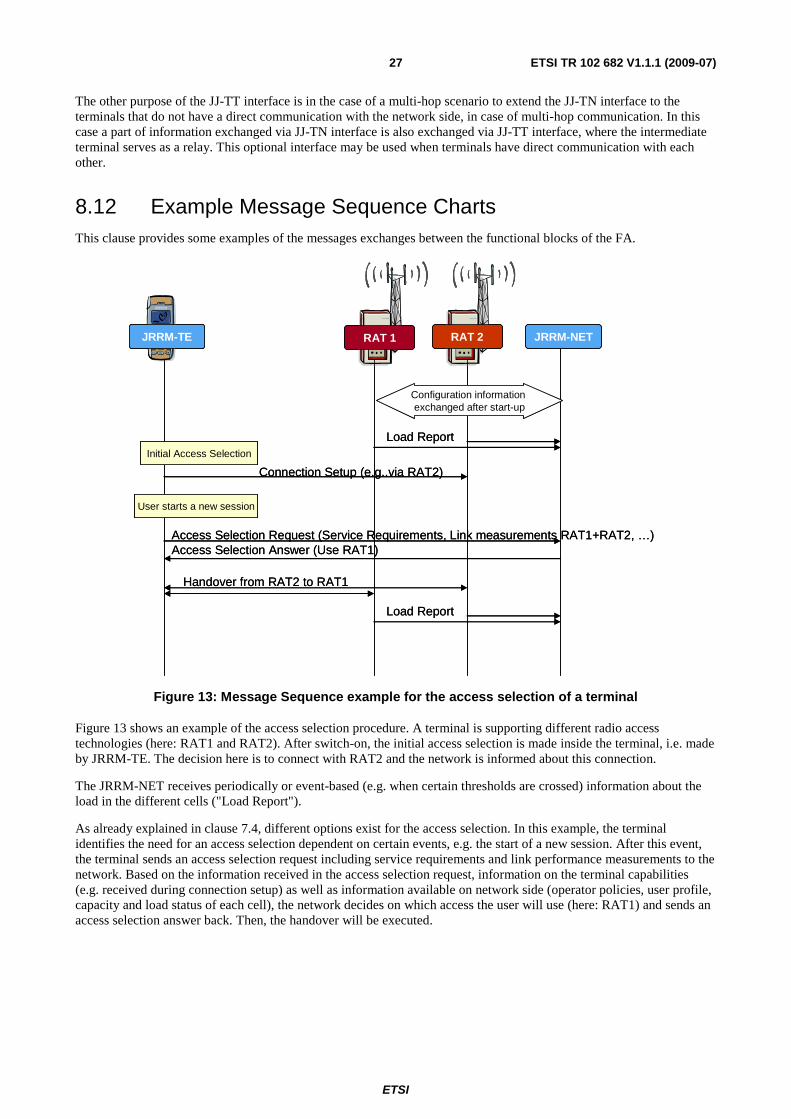
8.12 Example Message Sequence Charts This clause provides some examples of the messages exchanges between the functional blocks of the FA.
RAT 2RAT 1 JRRM-NETJRRM-TE
Load ReportInitial Access Selection
Connection Setup (e.g..via RAT2)
User starts a new session
Access Selection Request (Service Requirements, Link measurements RAT1+RAT2, …)Access Selection Answer (Use RAT1)
Handover from RAT2 to RAT1
Load Report
Configuration information exchanged after start-up
Figure 13: Message Sequence example for the access selection of a terminal
Figure 13 shows an example of the access selection procedure. A terminal is supporting different radio access technologies (here: RAT1 and RAT2). After switch-on, the initial access selection is made inside the terminal, i.e. made by JRRM-TE. The decision here is to connect with RAT2 and the network is informed about this connection.
The JRRM-NET receives periodically or event-based (e.g. when certain thresholds are crossed) information about the load in the different cells ("Load Report").
As already explained in clause 7.4, different options exist for the access selection. In this example, the terminal identifies the need for an access selection dependent on certain events, e.g. the start of a new session. After this event, the terminal sends an access selection request including service requirements and link performance measurements to the network. Based on the information received in the access selection request, information on the terminal capabilities (e.g. received during connection setup) as well as information available on network side (operator policies, user profile, capacity and load status of each cell), the network decides on which access the user will use (here: RAT1) and sends an access selection answer back. Then, the handover will be executed.

ETSI
ETSI TR 102 682 V1.1.1 (2009-07) 28
RAT 1..nRAT 1..nRAT 1..n JRRM-NET CCM-NET DSONPM DSM
Configure load measurements
Load measurements
Context update (load imbalance)
Spectrum request
Spectrum AssignmentReconfiguration command
Offload traffic command
Traffic offloaded
Reconfiguration enforcement/execution
Execution of handovers
Detection of unbalanced resource usage
Optimisation Process
Current configuration already exchanged after start-up of the system
Figure 14: Message Sequence example for the reconfiguration of a base station
Figure 14 shows the example of the reconfiguration of a base station during operation. After start-up of the blocks of the system, context information is already exchanged between the different building blocks.
In a next step, the JRRM-NET configures load measurements towards the different cells in the different RATs. Load measurements are then sent from the different RATs to the JRRM-NET, e.g. periodically as well as event based (crossing of certain load thresholds).
The JRRM-NET evaluates the load measurements and - besides using this information for access selection decisions as shown in the previous example - in the case of detecting an unbalanced usage of the resources, informs the DSONPM that there may be a need for a reconfiguration of the network or a base station ("Context update").
The DSONPM evaluates the current network status and tries to find a better configuration. This may include the usage of a different or additional spectrum which has to be negotiated with the DSM ("Spectrum request", "Spectrum assignment").
In the case that the DSONPM decides that the network or base station has to be reconfigured, a reconfiguration command is sent to the CCM-NET. In the case that only some parameters need to be optimized or reconfigured, the CCM-NET directly instructs the underlying RATs to do so.
In the case of a larger reconfiguration, e.g. that a base station (or a part of it) has to be reconfigured towards another RAT (e.g. LTE instead of UMTS), then to avoid service interruptions, the CCM-NET instructs the JRRM-NET to offload all traffic to other cells. After sending access selection decisions/handover commands to the terminals and supervising the success of the handovers, the JRRM-NET reports to the CCM-NET that the traffic is offloaded and then the CCM-NET executes the reconfiguration in the underlying RATs ("Reconfiguration enforcement/execution").

ETSI
ETSI TR 102 682 V1.1.1 (2009-07) 29
9 Summary and Recommendation for Standardization Summary
The present document has provided a feasibility study on defining a Functional Architecture (FA) for the Management and Control of Reconfigurable Radio Systems (RRS), in terms of collecting and putting together all management and control mechanisms that are targeted for improving the utilization of spectrum and the available radio resources. This denotes the specification of the major functional entities that manage and direct the operation of a reconfigurable radio system, as well as their operation and interactions, focusing on the interfaces among them that enable the necessary information exchange.
The need for standardization (why standardization is needed)
The need of standardization for Reconfigurable Radio Systems can be identified as follows:
In a regulatory context of liberalization where stakeholders (e.g. mobile operators, broadcasters, etc.) are coming from heterogeneous backgrounds with different geography, different objectives and different access methods to the spectrum resource, standardization is a way to deal with interoperability issues. From the economical viewpoint, standardization will have a role in facilitating the cooperation within the different stakeholders, leading to more productive business inter-relations. Also, stakeholders (among which operators) have estimated (see e.g. [i.15]) that some of the concepts developed in this Functional Architecture could allow OPEX reduction (e.g. by introducing self-configuration and optimization capabilities, by reducing the number of base stations, etc.). From the technical viewpoint, the proliferation of new technologies and the convergence of previously separated heterogeneous technologies are raising a need for standards.
Concrete technical examples where standards would be beneficial are listed below, in conjunction with the proposed FA for the Management and Control of Reconfigurable Radio Systems:
• Having standards in the areas covered by the proposed FA may help network operators and network business owners from various countries to face the increasing subscriber's need to reach a worldwide network, in a globalization context.
• From an operator viewpoint, it is desirable to be able to diversify the range of its equipment vendors. In this respect, the standardization of the interfaces between functional blocks (JRRM, CCM, DSONPM, etc.) as defined in this FA will be very beneficial.
• A cognitive radio network will need standards to avoid interferences, enhance the speed and the efficiency of this type of operation providing terminal user's satisfaction.
• In the light of the above argument, in order to permit software reconfiguration in specific situations, standards in general will help platform modules developers to become efficient stakeholders in this new network architecture. The reconfiguration management will have to comply with a number of interfaces between some elements, as set by standards.
Recommendations on what should be standardized in ETSI TC RRS
Based on the above arguments, the present document has provided inputs for a possible standardization of some or all topics of the FA above described, i.e.:
• Functional architecture of reconfigurable radio systems, meaning the proposed functional blocks that are necessary for the management and control of radio resources in reconfigurable radio systems.
• Specification of interfaces among the FA functional blocks, so as to facilitate the production of the functional blocks by various vendors, intercommunicating through standardizes interfaces. It has to be noted that standardization in ETSI should focus on those interfaces which are not subject of standardization in other bodies (see Annex for information on ongoing work in other standardization bodies).
• Specification of the protocol messages to be exchanged among the FA functional blocks.
Each of the recommended topics may become a new Work Item under TC RRS or they may be clustered in an appropriate way to support the ETSI Members to contribute into the specifications.
ETSI
ETSI TR 102 682 V1.1.1 (2009-07) 30
Annex A: Relationship between IEEE 1900.4 system and ETSI RRS FA
A.1 Introduction IEEE 1900.4 standard has been published in February 2009 [i.9]. It describes management system that enables optimized radio resource usage in heterogeneous wireless access networks. The present document provides mechanisms for equipment reconfiguration on both network and terminal sides. The areas of application of IEEE 1900.4 system and ETSI RRS FA are very similar. This informative Annex describes relationship between IEEE 1900.4 system and ETSI RRS FA.
First, this annex gives a brief overview of IEEE 1900.4 system. For a more detailed description, please refer to tutorial-like publications [i.10] and [i.9]. Then, description of the relationship between IEEE 1900.4 and ETSI RRS entities/modules and interfaces is provided.
A.2 IEEE 1900.4 Standard Overview
A.2.1 Introduction IEEE 1900.4 standard [i.9] defines management system to support network-terminal distributed optimization of radio resource usage and associated QoS improvement, in heterogeneous wireless networks.
This is done by defining the system and functional requirements, system and functional architecture, information model, and generic procedures for radio resource and associated QoS optimization. Further informative parts of the standard describe use cases and deployment examples for the developed system.
This annex gives an overview of 1900.4 architecture.
A.2.2 1900.4 Context The IEEE 1900.4 standard [i.9] considers the heterogeneous wireless environment shown in figure A.1. Such an environment may include multiple operators each operating one or several RANs. These RANs might utilize a range of different radio interfaces to communicate with terminals.
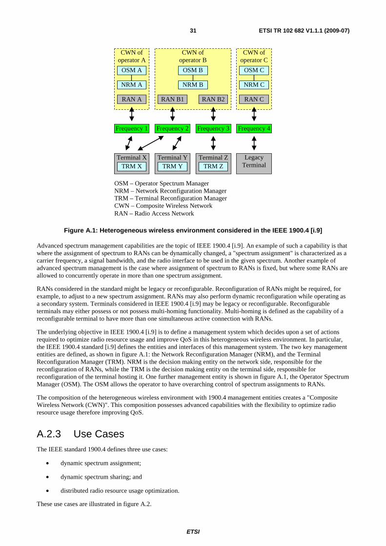
ETSI
ETSI TR 102 682 V1.1.1 (2009-07) 31
CWN of operator B
CWN of operator C
RAN B1
OSM B
CWN of operator A
RAN A
OSM A
RAN C
Terminal X
NRM B NRM A
TRM X
Frequency 1
RAN B2
Frequency 2 Frequency 3
OSM C
NRM C
Frequency 4
Legacy Terminal
Terminal Y TRM Y
OSM – Operator Spectrum Manager NRM – Network Reconfiguration Manager TRM – Terminal Reconfiguration Manager CWN – Composite Wireless Network RAN – Radio Access Network
Terminal Z TRM Z
Figure A.1: Heterogeneous wireless environment considered in the IEEE 1900.4 [i.9]
Advanced spectrum management capabilities are the topic of IEEE 1900.4 [i.9]. An example of such a capability is that where the assignment of spectrum to RANs can be dynamically changed, a "spectrum assignment" is characterized as a carrier frequency, a signal bandwidth, and the radio interface to be used in the given spectrum. Another example of advanced spectrum management is the case where assignment of spectrum to RANs is fixed, but where some RANs are allowed to concurrently operate in more than one spectrum assignment.
RANs considered in the standard might be legacy or reconfigurable. Reconfiguration of RANs might be required, for example, to adjust to a new spectrum assignment. RANs may also perform dynamic reconfiguration while operating as a secondary system. Terminals considered in IEEE 1900.4 [i.9] may be legacy or reconfigurable. Reconfigurable terminals may either possess or not possess multi-homing functionality. Multi-homing is defined as the capability of a reconfigurable terminal to have more than one simultaneous active connection with RANs.
The underlying objective in IEEE 1900.4 [i.9] is to define a management system which decides upon a set of actions required to optimize radio resource usage and improve QoS in this heterogeneous wireless environment. In particular, the IEEE 1900.4 standard [i.9] defines the entities and interfaces of this management system. The two key management entities are defined, as shown in figure A.1: the Network Reconfiguration Manager (NRM), and the Terminal Reconfiguration Manager (TRM). NRM is the decision making entity on the network side, responsible for the reconfiguration of RANs, while the TRM is the decision making entity on the terminal side, responsible for reconfiguration of the terminal hosting it. One further management entity is shown in figure A.1, the Operator Spectrum Manager (OSM). The OSM allows the operator to have overarching control of spectrum assignments to RANs.
The composition of the heterogeneous wireless environment with 1900.4 management entities creates a "Composite Wireless Network (CWN)". This composition possesses advanced capabilities with the flexibility to optimize radio resource usage therefore improving QoS.
A.2.3 Use Cases The IEEE standard 1900.4 defines three use cases:
• dynamic spectrum assignment;
• dynamic spectrum sharing; and
• distributed radio resource usage optimization.
These use cases are illustrated in figure A.2.

ETSI
ETSI TR 102 682 V1.1.1 (2009-07) 32
RAT 1 RAT 2
Frequency band 1
Frequency band 2
RAT 3 RAT 4
Frequency band 3
RAT 5
Frequency band 4
RAT 6
Frequency band 5
Dynamic spectrum assignment
Dynamic spectrum sharing
Distributed radio resource usage optimization
Figure A.2: IEEE 1900.4 [i.9] use cases
In the dynamic spectrum assignment use case, frequency bands are dynamically assigned to RANs in order to optimize radio resource usage and improve QoS. The OSM generates spectrum assignment policies expressing the regulatory framework as well as the operator's objectives for spectrum usage optimization. The OSM then provides these spectrum assignment policies to its corresponding NRM, whereby each NRM analyzes these received policies and available context information, and dynamically makes assignment decisions using these inputs. After the new spectrum assignment decisions have been made, each NRM requests corresponding reconfigurations of its RANs. Following RAN reconfigurations, terminals may also need to reconfigure.
In the dynamic spectrum sharing use case, frequency bands assigned to RANs are fixed; however, a particular frequency band can be shared by several RANs in order to optimize radio resource usage and improve QoS. NRMs analyze available context information and dynamically make decisions about whether to access new frequency band. Following these decisions, NRMs request corresponding reconfigurations of their RANs. Also, NRMs dynamically generate radio resource selection policies, and send them to their TRMs. TRMs then analyze these radio resource selection policies and available context information, and dynamically make decisions as to whether their terminals should access new frequency bands; these decisions are made within the framework of the radio resource selection policies as conveyed by the NRM. Following these decisions, TRMs request corresponding reconfigurations of their terminals, where necessary. It should be noted that the dynamic spectrum sharing use case includes the primary/secondary spectrum usage scenario as a special case.
In the distributed radio resource usage optimization use case, frequency bands assigned to RANs are fixed. Furthermore, the reconfiguration of RANs is not considered, instead, the topic is constrained to reconfigurable terminals with or without multi-homing capability. In this use case, NRMs analyze available context information, dynamically generate radio resource selection policies, and send them to their TRMs. TRMs analyze these radio resource selection policies and available context information, and dynamically make decisions on reconfigurations of their terminals in order to improve radio resource usage and QoS. Again, these decisions are made within the framework of the radio resource selection policies conveyed by NRMs. Following these decisions, TRMs request corresponding reconfigurations of their terminals, where necessary.
A.2.4 Architecture The architecture defined in the IEEE 1900.4 standard [i.9] is shown in figure A.3.The standard specifies four management entities on network side, three management entities on terminal side, and six interfaces between these entities.

ETSI
ETSI TR 102 682 V1.1.1 (2009-07) 33
TRC
TRM
TMC
RAN1
RANN
RMC RRC
OSM
NRM
Terminal Packet based core
network
TRC – Terminal Reconfiguration Controller TRM – Terminal Reconfiguration Manager TMC – Terminal Measurement Collector RMC – RAN Measurement Collector RRC – RAN Reconfiguration Controller OSM – Operator Spectrum Manager NRM – Network Reconfiguration Manager RAN – radio access network
Figure A.3: Architecture defined in IEEE 1900.4 standard [i.9]
The management entities on network side are:
• Operator Spectrum Manager (OSM);
• RAN Measurement Collector (RMC);
• Network Reconfiguration Manager (NRM); and
• RAN Reconfiguration Controller (RRC).
Operator Spectrum Manager is the entity that enables operator to control dynamic spectrum assignment decisions to be made by NRM.
For this purpose, the standard defines spectrum assignment policies. These policies express regulatory framework, defining spectrum usage rules for the frequency bands available to this operator. Also, these policies express operator objectives in radio resource usage optimization related to dynamic spectrum assignment. Spectrum assignment policies are sent from OSM to NRM.
RAN Measurement Collector is the entity that collects RAN context information and provides it to the NRM.
RAN context information, as defined in 1900.4, may include the following:
• RAN radio resource optimization objectives;
• RAN radio capabilities;
• RAN measurements; and
• RAN transport capabilities.
Network Reconfiguration Manager is the entity that manages CWNs and terminals for network-terminal distributed optimization of radio resource usage and improvement in QoS.
On network side, NRM makes RAN reconfiguration decisions and sends RAN reconfiguration requests to RRC. In other words, NRM directly decides on reconfiguration of RANs related to dynamic spectrum assignment and dynamic spectrum sharing.

ETSI
ETSI TR 102 682 V1.1.1 (2009-07) 34
For managing terminal reconfiguration by NRM, the standard defines radio resource selection policies. These policies are sent from NRM to TRMs under its management and create the framework within which, TRMs will make terminal reconfiguration decisions.
To ensure stable operation of CWNs, radio resource selection policies may include the maximum time interval for reconfiguration. The reconfiguration of a terminal is performed within this time interval starting from the time when this terminal has received these policies.
RAN Reconfiguration Controller is the entity that controls reconfiguration of RANs based on requests from the NRM.
To support scalable operation, RMC, NRM, RRC may be implemented in a distributed manner.
The management entities on terminal side are:
• Terminal Measurement Collector (TMC);
• Terminal Reconfiguration Manager (TRM); and
• Terminal Reconfiguration Controller (TRC).
Each terminal has one TMC, one TRM, and one TRC.
Terminal Measurement Collector is the entity that collects terminal context information and provides it to TRM.
Terminal context information defined in 1900.4 may include the following:
• User preferences;
• Required QoS levels;
• Terminal capabilities;
• Terminal measurements; and
• Terminal geo-location information.
Terminal Reconfiguration Manager is the entity that manages the terminal for network-terminal distributed optimization of radio resource usage and improvement of QoS. This optimization is performed within the framework defined by the NRM and expressed by radio resource selection policies, and in a manner consistent with user preferences.
Terminal Reconfiguration Controller is the entity that controls the reconfiguration of terminal based on requests from TRM.
Correspondingly, six interfaces specified in the IEEE 1900.4 standard [i.9] are used as described in the following (see figure A.3).
The interface between NRM and TRM is used to transmit the following:
• From NRM to TRM:
- Radio resource selection policies;
- RAN context information; and
- Terminal context information related to other terminals.
• From TRM to NRM:
- Terminal context information related to terminal of this TRM.
Two options are considered for the physical implementation of this interface. One option, termed out-band signalling, is to use a dedicated RAN. The other option, termed in-band signalling, is to use RANs having active connections with terminals. IEEE 1900.4 [i.9] supports both options including also a combined variant.
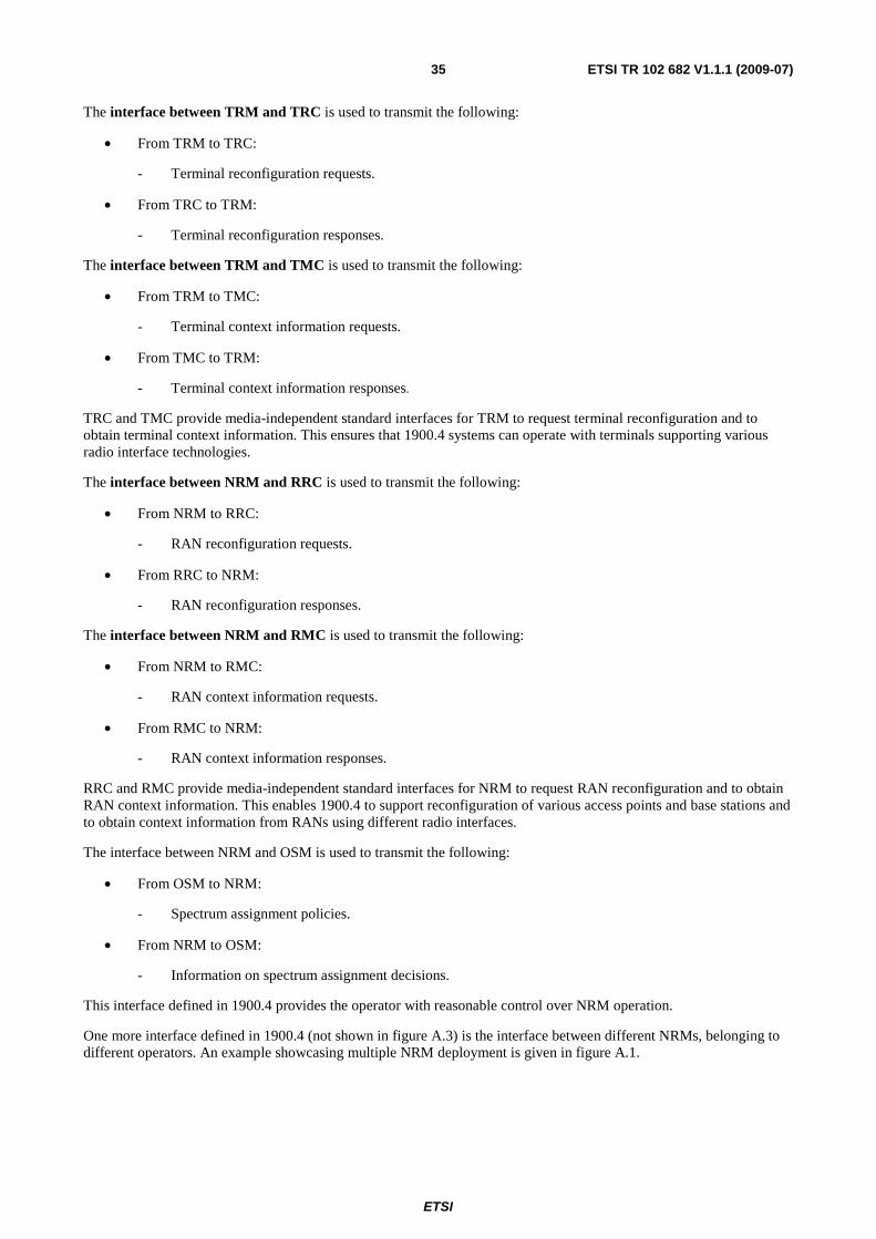
ETSI
ETSI TR 102 682 V1.1.1 (2009-07) 35
The interface between TRM and TRC is used to transmit the following:
• From TRM to TRC:
- Terminal reconfiguration requests.
• From TRC to TRM:
- Terminal reconfiguration responses.
The interface between TRM and TMC is used to transmit the following:
• From TRM to TMC:
- Terminal context information requests.
• From TMC to TRM:
- Terminal context information responses.
TRC and TMC provide media-independent standard interfaces for TRM to request terminal reconfiguration and to obtain terminal context information. This ensures that 1900.4 systems can operate with terminals supporting various radio interface technologies.
The interface between NRM and RRC is used to transmit the following:
• From NRM to RRC:
- RAN reconfiguration requests.
• From RRC to NRM:
- RAN reconfiguration responses.
The interface between NRM and RMC is used to transmit the following:
• From NRM to RMC:
- RAN context information requests.
• From RMC to NRM:
- RAN context information responses.
RRC and RMC provide media-independent standard interfaces for NRM to request RAN reconfiguration and to obtain RAN context information. This enables 1900.4 to support reconfiguration of various access points and base stations and to obtain context information from RANs using different radio interfaces.
The interface between NRM and OSM is used to transmit the following:
• From OSM to NRM:
- Spectrum assignment policies.
• From NRM to OSM:
- Information on spectrum assignment decisions.
This interface defined in 1900.4 provides the operator with reasonable control over NRM operation.
One more interface defined in 1900.4 (not shown in figure A.3) is the interface between different NRMs, belonging to different operators. An example showcasing multiple NRM deployment is given in figure A.1.

ETSI
ETSI TR 102 682 V1.1.1 (2009-07) 36
The interface between NRMs is used to transmit the following:
• RAN context information;
• terminal context information;
• spectrum assignment policies;
• RAN reconfiguration decisions; and
• radio resource selection policies.
In addition to the interfaces, IEEE 1900.4 standard [i.9] specifies three Service Access Points (SAPs):
• rCFG_TR_SAP - transport SAP.
• rCFG_MEDIA_SAP - reconfiguration and measurement SAP.
• rCFG_MNG_SAP - management SAP.
Each 1900.4 entity could have one or more of these SAPs.
Transport SAP provides transport service for message exchange between IEEE 1900.4 [i.9] entities. It abstracts transport mechanisms from IEEE 1900.4 [i.9] entities by providing a set of generic primitives and mapping these primitives on transport protocols.
For example, this SAP is used to exchange radio resource selection policies and context information between the NRM and the TRM over radio enabler. If there are several NRMs and there is interface between them, this SAP is used to exchange context information, spectrum assignment policies, reconfiguration decisions, and radio resource selection policies between these NRMs.
Reconfiguration and Measurement SAP provides reconfiguration and measurement services for managing RANs and terminals. It provides a set of generic primitives for IEEE 1900.4 [i.9] entities to collect RAN and terminal context information, as well as, to control reconfiguration of RANs and terminals. These generic primitives are mapped onto specific protocols depending on the managed RANs and terminals.
Management SAP provides management service for managing IEEE 1900.4 [i.9] entities by legacy management systems. This SAP provides a set of generic primitives for IEEE 1900.4 [i.9] entities to exchange information with these legacy management systems.
A.3 Relationship between IEEE 1900.4 system and ETSI RRS functional architecture
Relationship between IEEE 1900.4 [i.9] system and ETSI RRS FA is outlined in figure A.4.

ETSI
ETSI TR 102 682 V1.1.1 (2009-07) 37
Terminal
TRM
Operator
RMC RRC
NRM
DSONPM
RAT 1 RAT n
RAT 1 RAT n
TRC
TMC
MS
MC MJ
CJ
CR JR
CJ
CR JR
SS
MM
JJ-NN
JJ-TT
JJ-TN
Notations:
- Functional block of ETSI RRS FA
- Interface of ETSI RRS FA
- IEEE 1900.4 entity
- IEEE 1900.4 interface
- IEEE 1900.4 rCFG_MEDIA_SAP
OSM
To other NRM
To other TRM
CCM
CCM
JRRM
JRRM
DSM
Figure A.4: Relationship between IEEE 1900.4 [i.9] system and ETSI RRS FA
NRM entity is responsible for decision making on network side and for creating framework for decision making on terminal side by generating radio resource selection policies. Based on this functionality, NRM includes DSONPM functionality. Also, it includes the part of DSM functionality responsible for decision making on distribution of spectrum between RATs. Also, it includes some part of network JRRM functionality excluding obtaining context information from different RATs on network side. As long as network CCM is responsible for execution of base station self-configuration and self-optimization actions, this part of the network CCM functionality is included into NRM.
RRC entity is responsible for controlling RAN reconfiguration. Correspondingly, it includes some part of the network CCM excluding part included into NRM (see above) and part responsible for obtaining context information from different RATs on network side.
EXAMPLE 1: Base station capabilities.
RMC entity is responsible for obtaining RAN context information. Correspondingly, it includes the parts of network CCM and JRRM responsible for obtaining context information from different RATs on network side.

ETSI
ETSI TR 102 682 V1.1.1 (2009-07) 38
TRM entity is responsible for decision making on terminal side. Based on this functionality, TRM includes a part of terminal CCM functionality responsible for self-configuration and self-optimization actions and terminal JRRM excluding obtaining context information from different RATs in terminal.
TRC entity is responsible for controlling terminal reconfiguration. Correspondingly, it includes some part of the terminal CCM excluding part included into TRM (see above) and part responsible for obtaining context information from different RATs in terminal.
EXAMPLE 2: Terminal capabilities.
TMC entity is responsible for obtaining terminal context information. Correspondingly, it includes the parts of terminal CCM and JRRM responsible for obtaining context information from different RATs in terminal.
OSM entity serves as an external one to the decision making entity on network side, that is, NRM. OSM generates spectrum assignment policies expressing regulatory framework and operator objectives regarding dynamic spectrum assignment. Correspondingly, OSM includes the part of DSM responsible for obtaining regulatory framework and for spectrum trading between operators.
Relationship between IEEE 1900.4 [i.9] entities and ETSI RRS FA modules is summarized in table A.1.
Table A.1: Relationship between IEEE 1900.4 entities and ETSI RRS FA modules
IEEE 1900.4 entity ETSI RRS FA module NRM Part of DSM responsible for decision making on distribution of spectrum between
RATs. DSONPM. Network JRRM excluding:
• obtaining context information from different RATs on network side. Part of network CCM responsible for execution of base station self-configuration and self-optimization.
RRC Network CCM excluding: • part included into NRM; • part responsible for obtaining context information from different RATs on
network side. RMC Part of network CCM responsible for obtaining context information from different
RATs on network side. Part of network JRRM responsible for obtaining context information from different RATs on network side.
TRM Part of terminal CCM functionality responsible for self-configuration and self-optimization. Terminal JRRM excluding obtaining context information from different RATs in terminal.
TRC Terminal CCM excluding: • part included into TRM; • part responsible for obtaining context information from different RATs in
terminal. TMC Part of terminal CCM responsible for obtaining context information from different
RATs in terminal. Part of terminal JRRM responsible for obtaining context information from different RATs in terminal.
OSM Part of DSM responsible for obtaining regulatory framework and for spectrum trading between operators.
NRM � NRM interface is used to exchange context information, spectrum assignment decisions, radio resource selection policies, etc between NRMs of different operators. Correspondingly, this interface can be used to implement SS, MM and JJ-NN interfaces.
NRM � RRC interface is internal interface of network CCM module.
NRM � RMC interface is internal interface of network CCM and JRRM modules.
RRC rCFG_MEDIA_SAP provides media-dependent services for RAN reconfiguration. Correspondingly, this interface can be used to implement network CR interface.

ETSI
ETSI TR 102 682 V1.1.1 (2009-07) 39
RMC rCFG_MEDIA_SAP provides media-dependent services for obtaining RAN context information. Correspondingly, this interface can be used to implement part of network CR interface responsible for obtaining context information from different RATs on network side and network JR interface.
NRM � TRM interface is responsible for exchanging context information and radio resource selection policies between NRM and TRM. Correspondingly, this interface can be used to implement JJ-TN interface.
TRM � TRM interface is not defined in IEEE 1900.4 standard [i.9]. If defined in further extensions, it can be used to implement JJ-TT interface.
TRM � TRC interface is internal interface of terminal CCM module.
TRM � TMC interface is internal interface of terminal CCM and JRRM modules.
TRC rCFG_MEDIA_SAP provides media-dependent services for terminal reconfiguration. Correspondingly, this interface can be used to implement terminal CR interface.
TMC rCFG_MEDIA_SAP provides media-dependent services for obtaining terminal context information. Correspondingly, this interface can be used to implement part of terminal CR interface responsible for obtaining context information from different RATs on terminal side and terminal JR interface.
OSM � NRM interface is internal interface of DSM module.
MS, MC, MJ, and network CJ interfaces are not defined in IEEE 1900.4 standard [i.9]. They are considered as internal NRM interfaces and implementation dependent.
Terminal CJ interface is not defined in IEEE 1900.4 standard [i.9]. It is considered as internal TRM interface and implementation dependent.
Relationship between IEEE 1900.4 interfaces and ETSI RRS FA interfaces is summarized in table A.2.
Table A.2: Relationship between IEEE 1900.4 interfaces and ETSI RRS FA interfaces
IEEE 1900.4 interface ETSI RRS FA interface NRM � NRM SS, MM, JJ-NN NRM � RRC None (network CCM internal) NRM � RMC None (network CCM and JRRM internal) RRC rCFG_MEDIA_SAP Network CR RMC rCFG_MEDIA_SAP Network CR, network JR NRM � TRM JJ-TN None currently (maybe TRM � TRM in future) JJ-TT TRM � TRC None (terminal CCM internal) TRM � TMC None (terminal CCM and JRRM internal) TRC rCFG_MEDIA_SAP Terminal CR TMC rCFG_MEDIA_SAP Terminal CR, terminal JR OSM � NRM None (DSM internal) None (NRM internal) MS, MC, MJ, network CJ None (TRM internal) Terminal CJ

ETSI
ETSI TR 102 682 V1.1.1 (2009-07) 40
Annex B: Relationship between 3GPP standards and ETSI RRS FA
B.1 Introduction From its Release 8 forth, the 3GPP standard (for both UMTS and LTE) has introduced some functionalities which are related to either a better handling of multi-standards systems, or to self-x capabilities. Even if the wording "cognitive" is never used in the 3GPP specs, those features obviously introduce some kind of cognitive capabilities in the future 3GPP networks.
The purpose of this annex is not to summarize the 3GPP standard, but only to give a short summary of 5 functionalities that were recently developed within this standardization body:
1) Self-Organizing Networks (SON), Automatic Neighbour Relation (ANR).
2) Minimization of drive-tests.
3) Inter-Cell Interference Coordination (ICIC).
4) Multi-Standard Radio (MSR).
5) Access Network Discovery and Selection (ANDSF).
The above list is not exhaustive, but includes the most prominent functions in terms of cognitive/reconfigurability capabilities. Those features fall in the scope of what is studied by ETSI RRS. Hence it is important to highlight the possible relationships between 3GPP functions and RRS FA.
The last item of the list, the ANDSF, is not described here because it falls within the scope of the Cognitive Pilot Channel (CPC), and as such is already described in [i.11].
The second and third item of the list (Minimization of drive tests and ICIC) can somehow be seen as being part of the first one (SON), but formally speaking, they are described in separate 3GPP documents. Note that ICIC will not be described here, because this feature is more at the low radio level than at the system or architecture level.
B.2 Brief overview of 3GPP functionalities of interest
B.2.1 SON, ANR SON (Self Organizing Networks) have been recently introduced in 3GPP standardization in Release-8 and will be enhanced in Release 9. This was originated by the LTE standardization, but could be also extended to UMTS.
SON primary objective is to configure and optimize the network automatically. The expected benefit is twofold: to reduce human interaction, and increase the network capacity.
The basic framework consists of self-configuration /self-optimization functions, which respectively correspond to a pre-operational state and an operational state. This is summarized in figure B.1.

ETSI
ETSI TR 102 682 V1.1.1 (2009-07) 41
eNB power on
(or cable connected)
(A) Basic Setup
(B) Initial Radio
Configuration
(C) Optimization /
Adaptation
a-1 : configuration of IP address
and detection of OAM
a-2 : authentication of eNB/NW
a-3 : association to aGW
a-4 : downloading of eNB software
(and operational parameters)
b-2 : coverage/capacity related
parameter configuration
b-1 : neighbour list configuration
c-1 : neighbour list optimisation
c-2 : coverage and capacity control
Self-Configuration
(pre-operational state)
Self-Optimisation
(operational state)
Figure B.1: Framework of SON in 3GPP
Self-configuration and self-optimization functionalities are supported by specific UE measurements and procedures. Normal measurements should be used as most as possible, in order to minimize the impact on the UE.
As a key item of SON, the ANR (Automatic Neighbour Relation) function allows the operator to automatically set the neighbour relation of each cell. This function is particularly useful in the context of Home-Cells, because this corresponds in most cases to an un-coordinated deployment. So it is desirable that when a Home Cell is set-up, it automatically builds its internal list of neighbour cells, and that the Macro cells also dynamically and automatically maintain their list of neighbour cells.
The ANR function relies on the UE to report the cells that it has detected, but not in the neighbour list. The detected cell can be a cell within the same RAT and on the same frequency as the serving cell, or a different frequency in the same RAT, or even in a different RAT. The figure below shows a typical sequence where a UE populates Cell A with a neighbour Cell B information. Phy-CID stands for Physical Cell Identity, and Global-CID stands for Global Cell Identity.
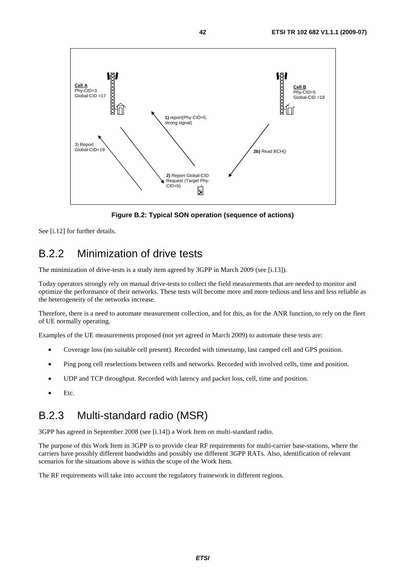
ETSI
ETSI TR 102 682 V1.1.1 (2009-07) 42
Cell A Phy-CID=3 Global-CID =17
Cell B Phy-CID=5 Global-CID =19
1) report(Phy-CID=5, strong signal)
2) Report Global-CID Request (Target Phy-CID=5)
2b) Read BCH()
3) Report Global-CID=19
Figure B.2: Typical SON operation (sequence of actions)
See [i.12] for further details.
B.2.2 Minimization of drive tests The minimization of drive-tests is a study item agreed by 3GPP in March 2009 (see [i.13]).
Today operators strongly rely on manual drive-tests to collect the field measurements that are needed to monitor and optimize the performance of their networks. These tests will become more and more tedious and less and less reliable as the heterogeneity of the networks increase.
Therefore, there is a need to automate measurement collection, and for this, as for the ANR function, to rely on the fleet of UE normally operating.
Examples of the UE measurements proposed (not yet agreed in March 2009) to automate these tests are:
• Coverage loss (no suitable cell present). Recorded with timestamp, last camped cell and GPS position.
• Ping pong cell reselections between cells and networks. Recorded with involved cells, time and position.
• UDP and TCP throughput. Recorded with latency and packet loss, cell, time and position.
• Etc.
B.2.3 Multi-standard radio (MSR) 3GPP has agreed in September 2008 (see [i.14]) a Work Item on multi-standard radio.
The purpose of this Work Item in 3GPP is to provide clear RF requirements for multi-carrier base-stations, where the carriers have possibly different bandwidths and possibly use different 3GPP RATs. Also, identification of relevant scenarios for the situations above is within the scope of the Work Item.
The RF requirements will take into account the regulatory framework in different regions.

ETSI
ETSI TR 102 682 V1.1.1 (2009-07) 43
B.3 Relationship between 3GPP standard and ETSI RRS functional architecture
Regarding Self-x functionalities, both ETSI RRS and 3GPP address Multi-RAT aspects. The difference is that ETSI RRS does not consider only 3GPP RATs, but all possible RATs. Anyhow, it is clear that the concepts developed by 3GPP, namely for the ANR function and the procedures considered for the minimization of drive-test, strongly overlap with the parts of the concepts developed in this Functional Architecture. However, at the moment, it is difficult to better highlight the relationship between both, e.g. provide a mapping, because in 3GPP many of the concepts mentioned are at the Study Item or Work Item level (i.e. no specification yet).
Regarding MSR (Multi-Standard Radio), it is felt that there is no strong relation with the Functional Architecture of ETSI RRS, because this 3GPP work item is focused on RF requirements only and not on architecture issues.

ETSI
ETSI TR 102 682 V1.1.1 (2009-07) 44
Annex C: Bibliography
• P. Houze et al: "IEEE 1900.4 WG: IEEE 1900.4 Standard Overview".
NOTE: Available at: http://grouper.ieee.org/groups/scc41/4/IEEE-1900.4-Overview-2009-01-07.pdf.

ETSI
ETSI TR 102 682 V1.1.1 (2009-07) 45
History
Document history
V1.1.1 July 2009 Publication