Embed Size (px)
Citation preview
93633
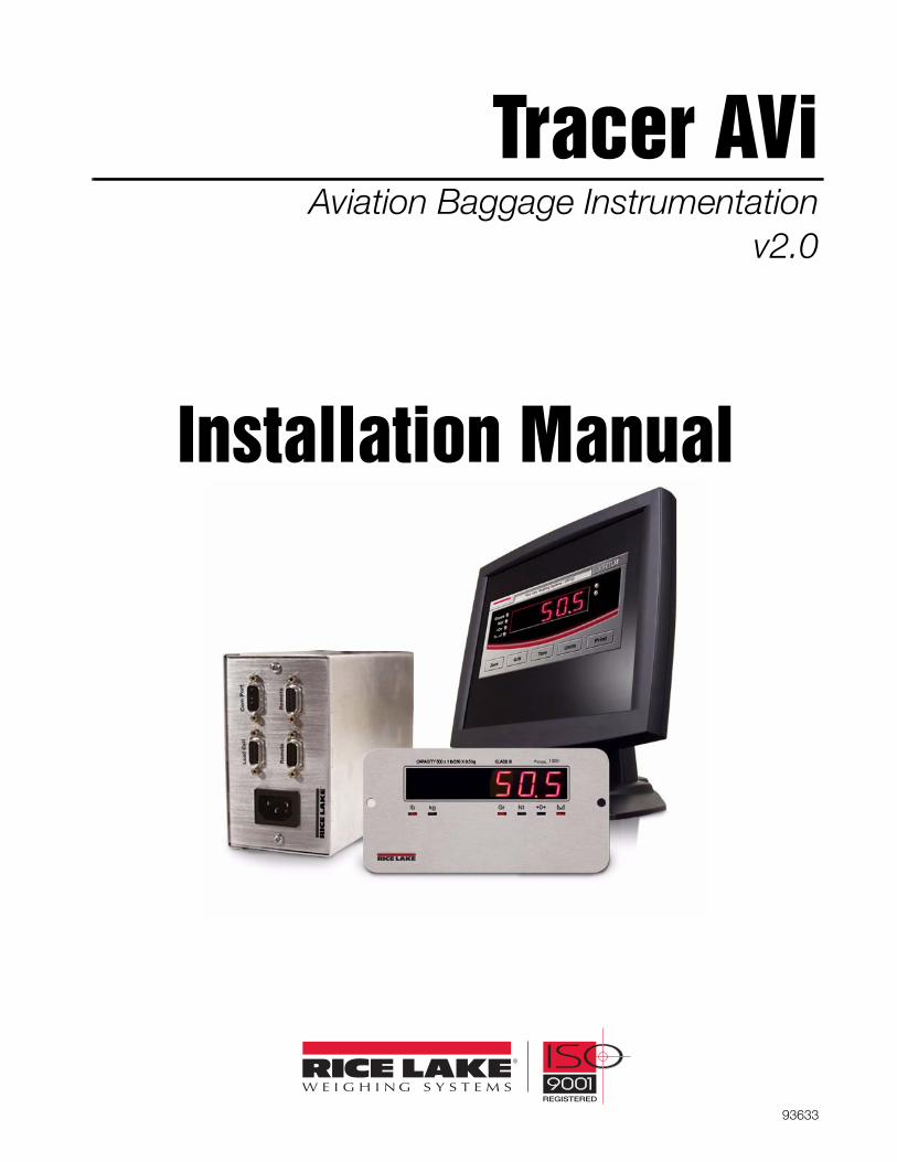
Tracer AViAviation Baggage Instrumentation
v2.0
Installation Manual

© 2008 Rice Lake Weighing Systems. All rights reserved. Printed in the United States of America. Specifications subject to change without notice.
November 2008
ContentsContents ................................................................................................................................................... iAbout This Manual ................................................................................................................................... 11.0 Introduction.................................................................................................................................. 12.0 Installation ................................................................................................................................... 2
2.1 Unpacking and Assembly . . . . . . . . . . . . . . . . . . . . . . . . . . . . . . . . . . . . . . . . . . . . . . . . . . . . . . . . 22.2 Enclosure Security/Disassembly . . . . . . . . . . . . . . . . . . . . . . . . . . . . . . . . . . . . . . . . . . . . . . . . . . 22.3 Mounting the iQube and Remote Display . . . . . . . . . . . . . . . . . . . . . . . . . . . . . . . . . . . . . . . . . . . 22.4 Cable Connections . . . . . . . . . . . . . . . . . . . . . . . . . . . . . . . . . . . . . . . . . . . . . . . . . . . . . . . . . . . . . 22.5 Load Cells . . . . . . . . . . . . . . . . . . . . . . . . . . . . . . . . . . . . . . . . . . . . . . . . . . . . . . . . . . . . . . . . . . . . 22.6 Serial Communications . . . . . . . . . . . . . . . . . . . . . . . . . . . . . . . . . . . . . . . . . . . . . . . . . . . . . . . . . . 32.7 Core Module DIP Switches . . . . . . . . . . . . . . . . . . . . . . . . . . . . . . . . . . . . . . . . . . . . . . . . . . . . . . . 42.8 Core Module Reset Procedure . . . . . . . . . . . . . . . . . . . . . . . . . . . . . . . . . . . . . . . . . . . . . . . . . . . . 42.9 The Power Supply . . . . . . . . . . . . . . . . . . . . . . . . . . . . . . . . . . . . . . . . . . . . . . . . . . . . . . . . . . . . . . 42.10 Fuse Replacement . . . . . . . . . . . . . . . . . . . . . . . . . . . . . . . . . . . . . . . . . . . . . . . . . . . . . . . . . . . . . 42.11 Interface Cables . . . . . . . . . . . . . . . . . . . . . . . . . . . . . . . . . . . . . . . . . . . . . . . . . . . . . . . . . . . . . . . 42.12 Replacement Parts and Drawings. . . . . . . . . . . . . . . . . . . . . . . . . . . . . . . . . . . . . . . . . . . . . . . . . 5
3.0 PC Configuration .......................................................................................................................... 73.1 Introduction to VIRTUi. . . . . . . . . . . . . . . . . . . . . . . . . . . . . . . . . . . . . . . . . . . . . . . . . . . . . . . . . . . 7
3.1.1 Authentication/Authorization System. . . . . . . . . . . . . . . . . . . . . . . . . . . . . . . . . . . . . . . . . . . . . . . . . . . 83.1.2 Communication . . . . . . . . . . . . . . . . . . . . . . . . . . . . . . . . . . . . . . . . . . . . . . . . . . . . . . . . . . . . . . . . . 103.1.3 Function Keys and Annunciators. . . . . . . . . . . . . . . . . . . . . . . . . . . . . . . . . . . . . . . . . . . . . . . . . . . . . 103.1.4 VIRTUi Operations . . . . . . . . . . . . . . . . . . . . . . . . . . . . . . . . . . . . . . . . . . . . . . . . . . . . . . . . . . . . . . . 103.1.5 Web Browser-Based Cell Status. . . . . . . . . . . . . . . . . . . . . . . . . . . . . . . . . . . . . . . . . . . . . . . . . . . . . 113.1.6 System Requirements. . . . . . . . . . . . . . . . . . . . . . . . . . . . . . . . . . . . . . . . . . . . . . . . . . . . . . . . . . . . . 11
3.2 VIRTUI Configuration. . . . . . . . . . . . . . . . . . . . . . . . . . . . . . . . . . . . . . . . . . . . . . . . . . . . . . . . . . . 123.2.1 Downloading to the Tracer AVi . . . . . . . . . . . . . . . . . . . . . . . . . . . . . . . . . . . . . . . . . . . . . . . . . . . . . 12
4.0 Calibration ................................................................................................................................. 135.0 Diagnostics ................................................................................................................................ 16
5.1 Diagnostic Tests . . . . . . . . . . . . . . . . . . . . . . . . . . . . . . . . . . . . . . . . . . . . . . . . . . . . . . . . . . . . . . 165.2 Diagnostic Setup . . . . . . . . . . . . . . . . . . . . . . . . . . . . . . . . . . . . . . . . . . . . . . . . . . . . . . . . . . . . . . 16
6.0 Specifications ............................................................................................................................ 17Tracer AVi Limited Warranty .................................................................................................................. 18
Technical training seminars are available through Rice Lake Weighing Systems.Course descriptions and dates can be viewed at www.ricelake.com or obtained by
calling 715-234-9171 and asking for the training department.

Introduction 1
About This ManualThis manual is intended for use by service techniciansresponsible for installing and servicing the Tracer AVisingle channel diagnostic junction box and bagwelldisplay.
Authorized distributors and their employeescan view or download this manual from theRice Lake Weighing Systems distributorsite at www.ricelake.com.
Some procedures described in this manualrequire work inside the iQube enclosure.These procedures are to be performed byqualified service personnel only.
The Tracer AVi does not have an on/off switch and thereforemust be installed near a power outlet that is easily accessibleand in accordance with UL/CSA Safety Standards.
1.0 IntroductionThe Tracer AVi system consists of three components:
• iQubeTM, a digital programmable junction boxused with an analog load cell. It outputs aserial string that can be directly input to theremote display and VIRTUi.
• RD-1 remote display, a .8”, six-digit,seven-segment LED display.
• VIRTUiTM, a PC-based indicator for iQube. Thevirtual front panel consists of display andfive-button keypad.
The iQube consists of three boards: • The connector board provides the physical
connec t ions fo r t he load ce l l , s e r i a lcommunications, and power.
• The core module, which plugs into theconnector board, contains the Tracer AVi’sprocessor and stores configuration andcalibration data for the Tracer AVi. The coremodule provides a discrete A/D input andconverts the analog load cell signal to a digitalserial output.
• The 7.5 VDC power supply mounts inside theenclosure and requires a 115/230 VAC input.
ConfigurationThe Tracer AVi system can be configured by using aPC running the VIRTUi configuration program. Thismethod defines the load cell connected to iQube,which is associated with a platform, and the platformtha t makes up t he s ca l e . E v e n t h o u g h t h esingle-channel iQube is just one cell, one platform, andone scale; the association of scale and platform isrequired because the software is also used on multiplecell and multiple platform scales.
Configuration consists of the following steps:Define Load Cell: This is the electrical sensitivity(mV/V output) and capacity specification of the loadcell. Load cell name and serial number can also bespecified.
Define Platforms: The iQube board must assign aload cell to the platform. Define System: The iQube board must assign theplatform to the system.
Load Cell Trimming and CalibrationiQube supports calibration of multiple load cells withcorner match and section match calibration. For the single cell iQube, only multi-point linearcalibration and theoretical calibration apply. Each typeof calibration captures the initial dead load of the scaleand provides a means to trim the output of the loadcell.Based on the cell capacity and sensitivity, thetheoretical calibration calculates weight values basedon the total signal from the cell.
Single Cell DiagnosticDiagnostic functionality can be enabled for the iQubeto identify abnormal load cell output. The diagnosticconditions that can be identified are open bridge openchannel, drifting, peak-to-peak noise, cell at rail, andcell over/under range.Error conditions generate a displayed error message ifconnected to VIRTUi which can be configured to emailthe alert message to an address.

2 Tracer AVi Installation Manual
2.0 InstallationThis section describes procedures for connecting loadcell, power, and serial communications cables to theiQubeTM enclosure. Drawings and replacement partslists are included for the service technician.
Use a wrist strap to ground yourself andprotect components from electrostaticdischarge (ESD) when working inside theiQube enclosure.
Disconnect AC power from the main module before installingremote displays.
2.1 Unpacking and AssemblyImmediately after unpacking, visually inspect thecontents to ensure all components are included andundamaged. The shipping carton should contain theiQube, the remote display, and connection cables. Ifany parts were damaged in shipment, notify Rice LakeWeighing Systems and the shipper immediately.See Table 2-4 on page 4 for information on the iQubecables.
2.2 Enclosure Security/DisassemblyAfter an NTEP inspector has examined the unit, he/she will install security cables pictured in Figure 2-1.These cables prevent the Tracer AVi from beingtampered with by an unauthorized individual. If thesecables are removed, NTEP certification will becomevoid.If the Tracer AVi enclosure must be opened by anauthorized technician, ensure power is disconnected,then place it on an anti-static work mat. Cut thetamper-proof cables, remove screws, and remove theenclosure’s cover. An NTEP inspector will have toexamine the unit and attach new security cables.
Figure 2-1. Security cables installed
2.3 Mounting the iQube and RemoteDisplay
The iQube and remote display are two separatecomponents. The main board is installed in the iQube.All components can be installed in separate locations.The iQube can be placed either upright or on its side.Mounting hardware is not included in the parts kit.
2.4 Cable ConnectionsThe single channel iQube provides one load cellconnector, two remote display connectors, one host(PC) com port connector for connecting to the PCrunning VIRTUi, and an AC power cord.
2.5 Load CellsThe load cell wired to connector J3 in the iQube, isassigned a default name A1. J3 is wired to a DB-9 onthe enclosure panel.
Load Cell WiringTo attach the load cell cable to the connector board,plug the cable into external connector (see Figure 2-6on page 6). Wire load cell cables as shown in Table 2-1.
!
DB-9 Pin Female Connector
On-Board Connector (J3) Function
7 1 +SIG
3 2 –SIG
4 3 +EXC
6 4 –EXC
5 5 SHIELD
Table 2-1. Load Cell Connector Pin Assignments
Installation 3
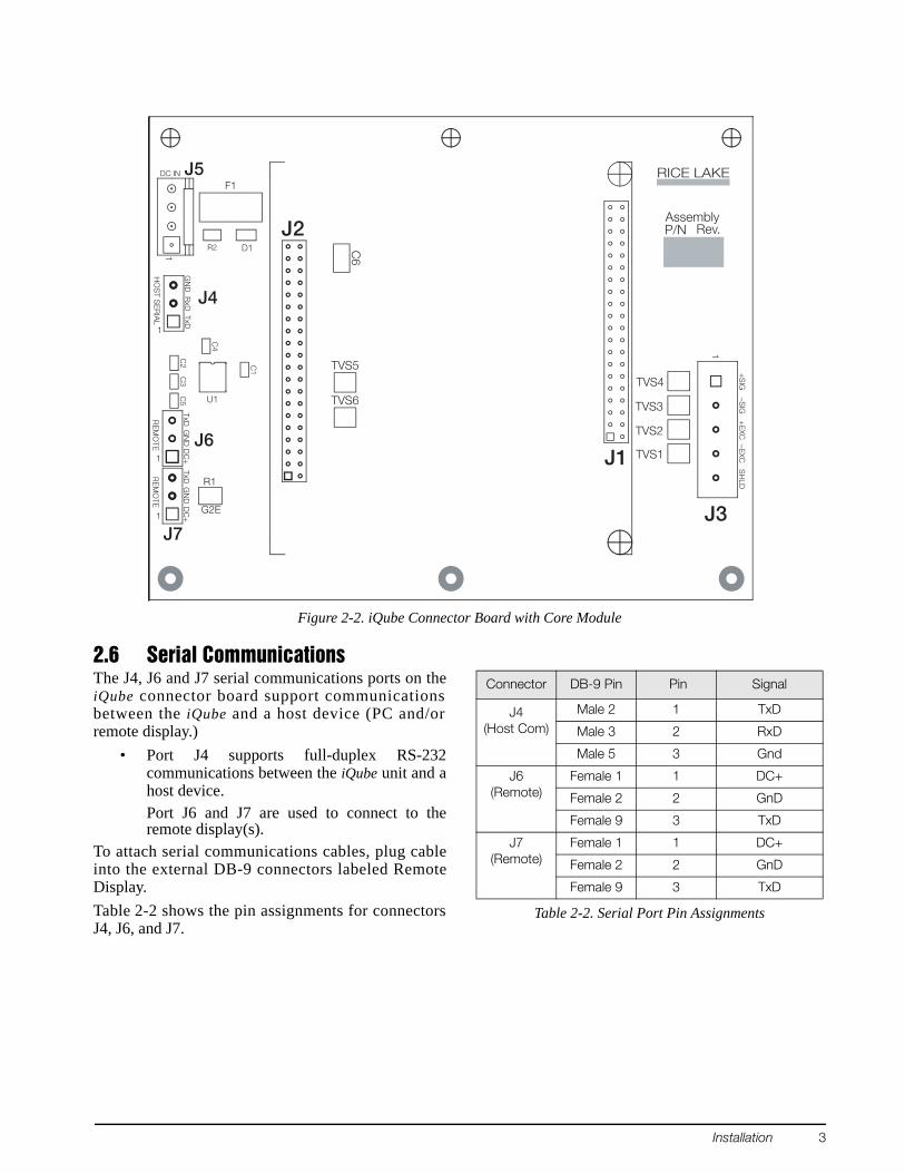
Figure 2-2. iQube Connector Board with Core Module
2.6 Serial CommunicationsThe J4, J6 and J7 serial communications ports on theiQube connector board support communicationsbetween the iQube and a host device (PC and/orremote display.)
• Port J4 supports full-duplex RS-232communications between the iQube unit and ahost device. Port J6 and J7 are used to connect to theremote display(s).
To attach serial communications cables, plug cableinto the external DB-9 connectors labeled RemoteDisplay.Table 2-2 shows the pin assignments for connectorsJ4, J6, and J7.
GN
DTxD
DC
+TxD
RxD
1
DC IN
1
DC
+G
ND
TxDG
ND
G2E1
RE
MO
TE
1
–EXC
+S
IG
Rev.P/N
RE
MO
TEH
OS
T SE
RIA
L
1
–SIG
+E
XC
Assembly
RICE LAKES
HLD
C3
R1
C4
R2 D1
C2
C5
J4
C1
J1J6
TVS6
TVS5
C6
J7
J5
J2
J3
TVS1
TVS4U1
TVS3
TVS2
F1
Connector DB-9 Pin Pin Signal
J4(Host Com)
Male 2 1 TxD
Male 3 2 RxD
Male 5 3 Gnd
J6(Remote)
Female 1 1 DC+
Female 2 2 GnD
Female 9 3 TxD
J7(Remote)
Female 1 1 DC+
Female 2 2 GnD
Female 9 3 TxD
Table 2-2. Serial Port Pin Assignments
4 Tracer AVi Installation Manual
Communications Cable Distance LimitationsThe maximum cable lengths that can be used forvarious communications types depend on a number offactors. These include: output impedance of thetransmitter; electrical noise in the environment; cablecapacitance, gauge, termination, and shielding. Given that these and other factors will affect themaximum usable cable length, the following distancesc a n b e u s e d a s a g e n e r a l g u i d e f o r i Q u b ecommunications cabling (10 ft cable is provided):
RS-232: 50 ft (15 m)
2.7 Core Module DIP SwitchesThe DIP switches on the iQube core module must beset to configure the iQube as a primary or secondaryunit, and to specify the type of serial communicationsprovided by the unit. Table 2-3 lists the DIP switchesand their functions.
2.8 Core Module Reset ProcedureIf VIRTUi does not recognize the connection to theload cell, the core module may need to be reset toinitialize the iQube firmware.To reload the default firmware into the iQube coremodule, do the following:
1. Power-off the iQube. Remotely powered unitscan be powered off by temporarily removingfuse F1 (see Figure 2-2 on page 3).
2. Set core module DIP switch 8 ON.3. Power-on the iQube.4. Power-off the iQube.5. Set DIP switch 8 OFF.6. Power-on the iQube. The reset is now complete.
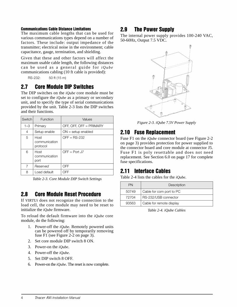
2.9 The Power SupplyThe internal power supply provides 100-240 VAC,50-60Hz, Output 7.5 VDC.
Figure 2-3. iQube 7.5V Power Supply
2.10 Fuse ReplacementFuse F1 on the iQube connector board (see Figure 2-2on page 3) provides protection for power supplied tothe connector board and core module at connector J5.Fuse F1 is poly resettable and does not needreplacement. See Section 6.0 on page 17 for completefuse specifications.
2.11 Interface CablesTable 2-4 lists the cables for the iQube.
Switch Function Values
1–3 Primary OFF, OFF, OFF = PRIMARY
4 Setup enable ON = setup enabled
5 Host communication protocol
OFF = RS-232
6 Host communication port
OFF = Port J7
7 Reserved OFF
8 Load default OFF
Table 2-3. Core Module DIP Switch SettingsPN Description
50749 Cable for com port to PC
72704 RS-232/USB connector
93563 Cable for remote display
Table 2-4. iQube Cables
Installation 5
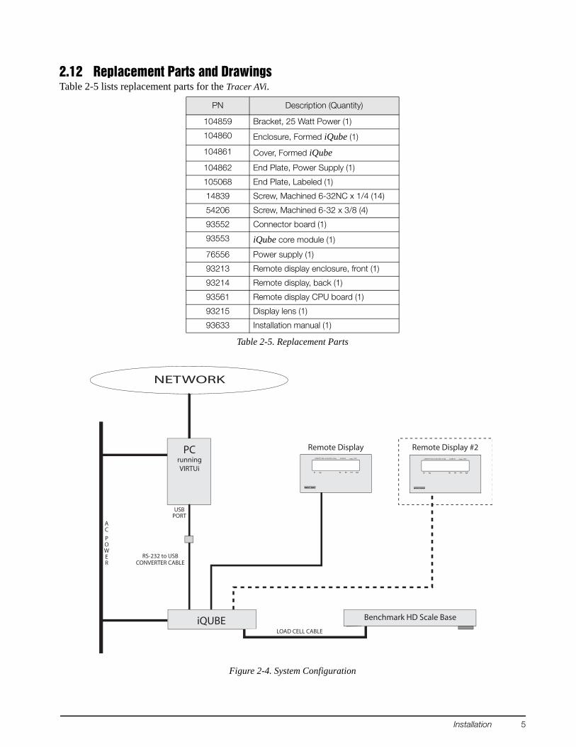
2.12 Replacement Parts and DrawingsTable 2-5 lists replacement parts for the Tracer AVi.
Figure 2-4. System Configuration
PN Description (Quantity)
104859 Bracket, 25 Watt Power (1)
104860 Enclosure, Formed iQube (1)
104861 Cover, Formed iQube104862 End Plate, Power Supply (1)
105068 End Plate, Labeled (1)
14839 Screw, Machined 6-32NC x 1/4 (14)
54206 Screw, Machined 6-32 x 3/8 (4)
93552 Connector board (1)
93553 iQube core module (1)
76556 Power supply (1)
93213 Remote display enclosure, front (1)
93214 Remote display, back (1)
93561 Remote display CPU board (1)
93215 Display lens (1)
93633 Installation manual (1)
Table 2-5. Replacement Parts
NETWORK
PCrunningVIRTUi
RS-232 to USBCONVERTER CABLE
Grkglb Nt
CAPACITY 500 x 0.5lb/250 x 0.2kg CLASS III nmax. 1000
Remote Display Remote Display #2
Grkglb Nt
CAPACITY 500 x 0.5lb/250 x 0.2kg CLASS III nmax. 1000
iQUBELOAD CELL CABLE
Benchmark HD Scale Base
AC
POWER
USBPORT
6 Tracer AVi Installation Manual
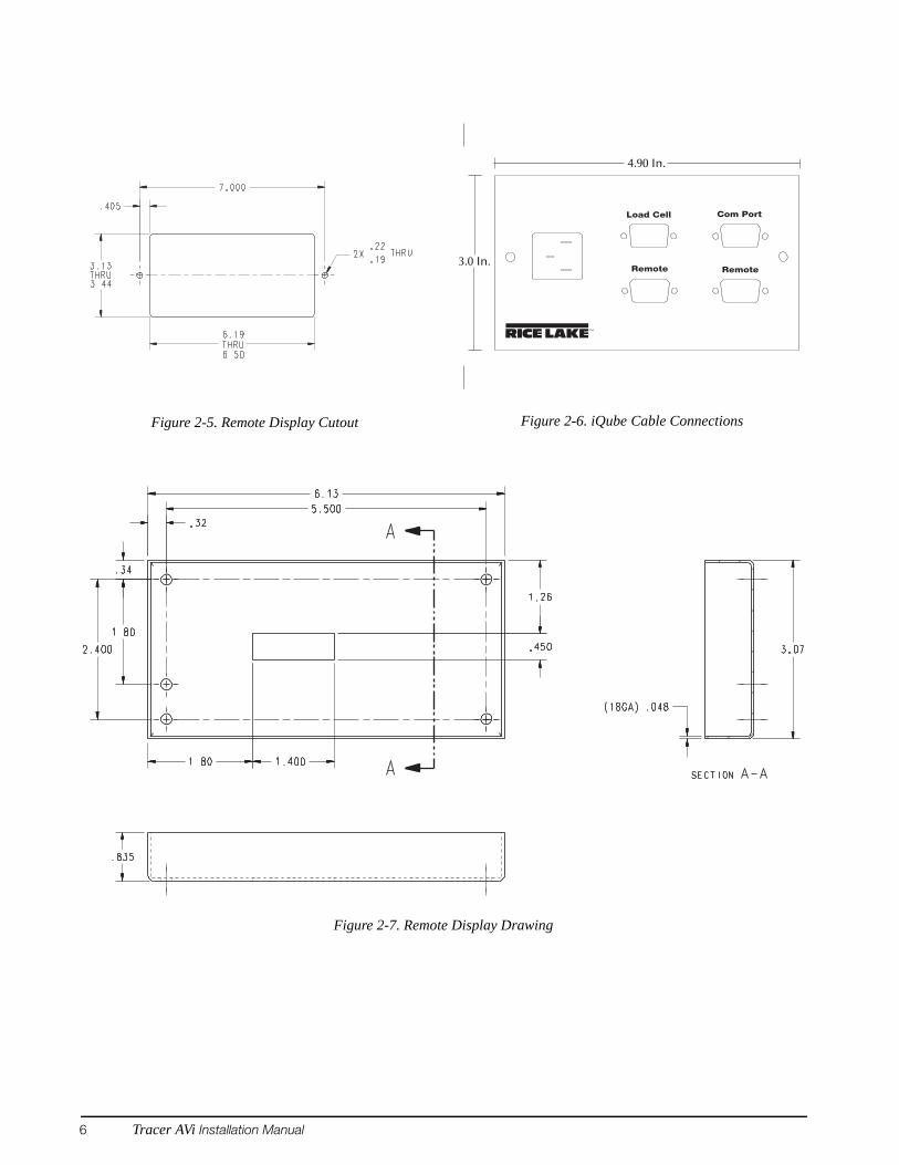
Figure 2-5. Remote Display Cutout Figure 2-6. iQube Cable Connections
Figure 2-7. Remote Display Drawing
TM
Remote Remote
Load Cell Com Port
4.90 In.
3.0 In.
PC Configuration 7
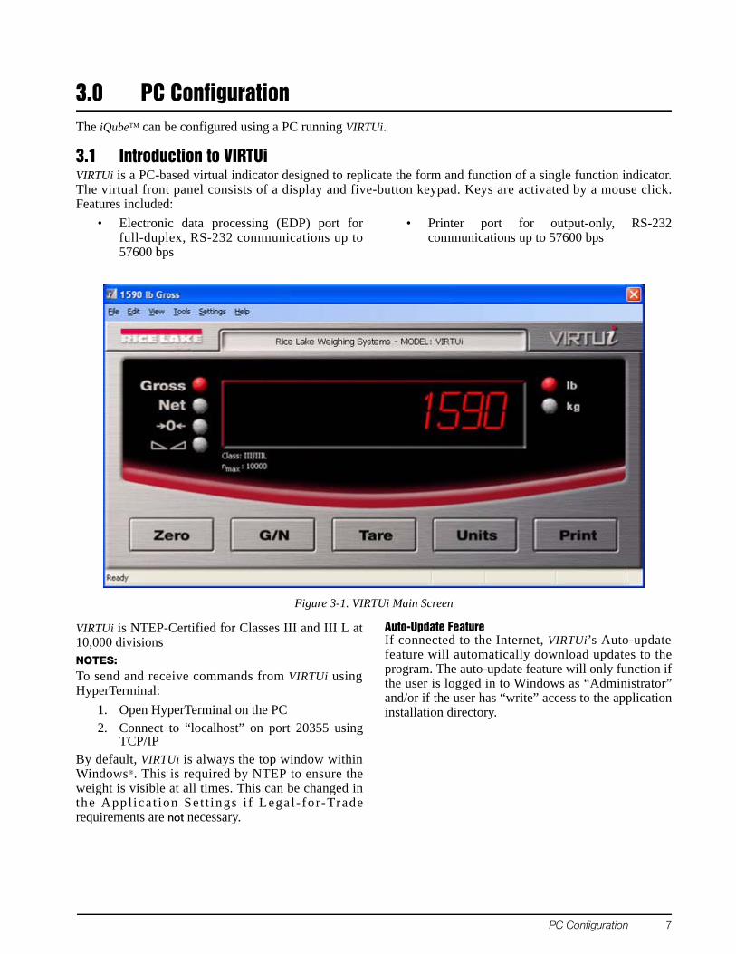
3.0 PC ConfigurationThe iQubeTM can be configured using a PC running VIRTUi.
3.1 Introduction to VIRTUi VIRTUi is a PC-based virtual indicator designed to replicate the form and function of a single function indicator.The virtual front panel consists of a display and five-button keypad. Keys are activated by a mouse click.Features included:
• Electronic data processing (EDP) port forfull-duplex, RS-232 communications up to57600 bps
• Printer port for output-only, RS-232communications up to 57600 bps
Figure 3-1. VIRTUi Main Screen
VIRTUi is NTEP-Certified for Classes III and III L at10,000 divisionsNOTES: To send and receive commands from VIRTUi usingHyperTerminal:
1. Open HyperTerminal on the PC2. Connect to “localhost” on port 20355 using
TCP/IPBy default, VIRTUi is always the top window withinWindows®. This is required by NTEP to ensure theweight is visible at all times. This can be changed inthe Appl ica t ion Set t ings i f Legal - for-Traderequirements are not necessary.
Auto-Update FeatureIf connected to the Internet, VIRTUi’s Auto-updatefeature will automatically download updates to theprogram. The auto-update feature will only function ifthe user is logged in to Windows as “Administrator”and/or if the user has “write” access to the applicationinstallation directory.
8 Tracer AVi Installation Manual
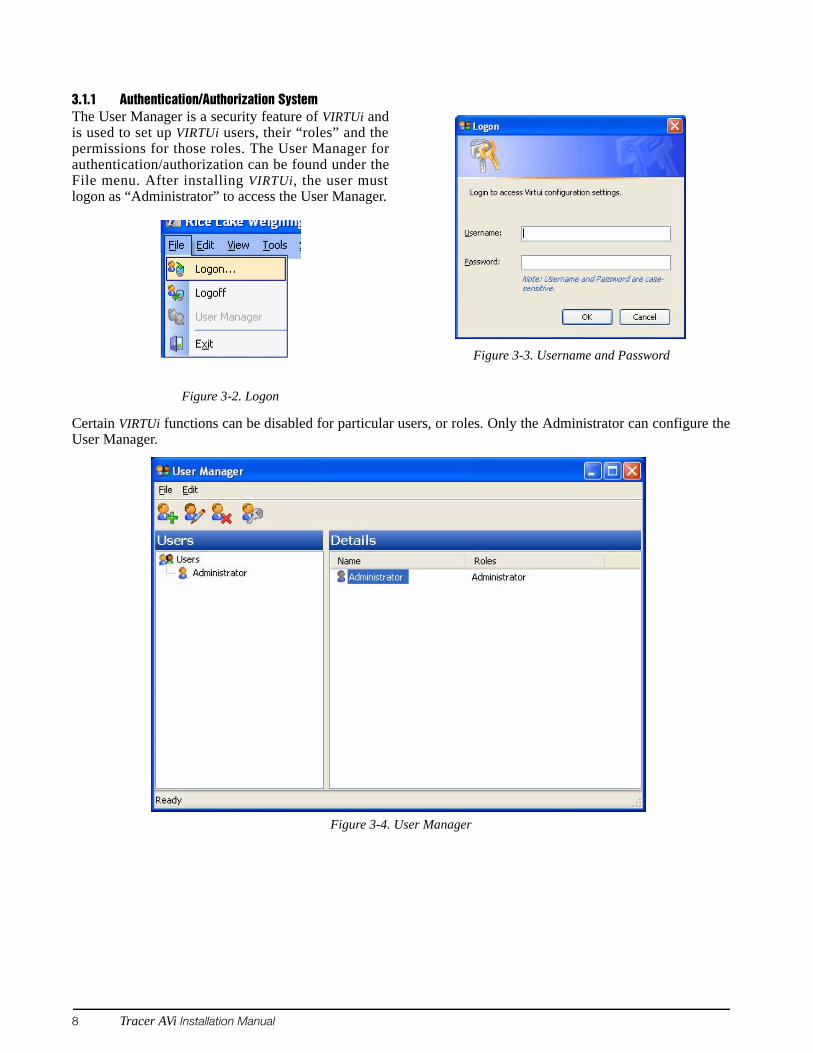
3.1.1 Authentication/Authorization SystemThe User Manager is a security feature of VIRTUi andis used to set up VIRTUi users, their “roles” and thepermissions for those roles. The User Manager forauthentication/authorization can be found under theFile menu. After installing VIRTUi, the user mustlogon as “Administrator” to access the User Manager.
Figure 3-2. Logon
Figure 3-3. Username and Password
Certain VIRTUi functions can be disabled for particular users, or roles. Only the Administrator can configure theUser Manager.
Figure 3-4. User Manager
PC Configuration 9
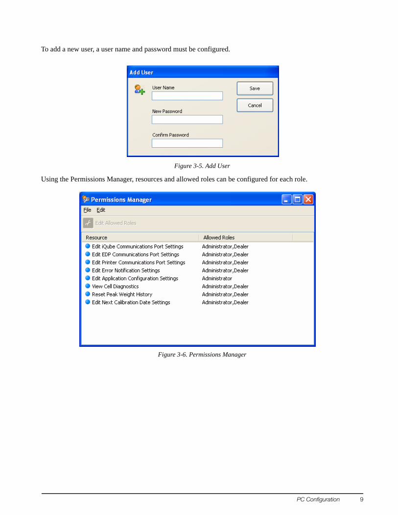
To add a new user, a user name and password must be configured.
Figure 3-5. Add User
Using the Permissions Manager, resources and allowed roles can be configured for each role.
Figure 3-6. Permissions Manager
10 Tracer AVi Installation Manual
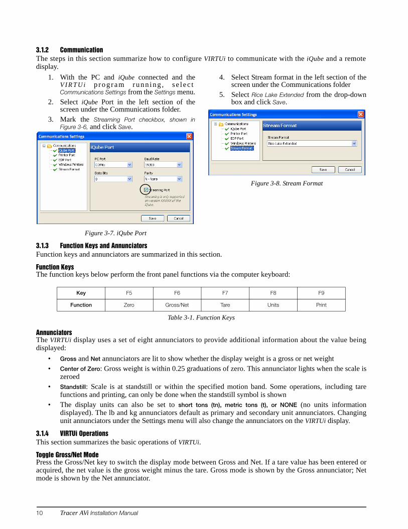
3.1.2 CommunicationThe steps in this section summarize how to configure VIRTUi to communicate with the iQube and a remotedisplay.
1. With the PC and iQube connected and theV I R T U i p r o g r a m r u n n i n g , s e l e c tCommunications Settings from the Settings menu.
2. Select iQube Port in the left section of thescreen under the Communications folder.
3. Mark the Streaming Port checkbox, shown inFigure 3-6, and click Save.
Figure 3-7. iQube Port
4. Select Stream format in the left section of thescreen under the Communications folder
5. Select Rice Lake Extended from the drop-downbox and click Save.
Figure 3-8. Stream Format
3.1.3 Function Keys and AnnunciatorsFunction keys and annunciators are summarized in this section.
Function KeysThe function keys below perform the front panel functions via the computer keyboard:
AnnunciatorsThe VIRTUi display uses a set of eight annunciators to provide additional information about the value beingdisplayed:
• Gross and Net annunciators are lit to show whether the display weight is a gross or net weight• Center of Zero: Gross weight is within 0.25 graduations of zero. This annunciator lights when the scale is
zeroed• Standstill: Scale is at standstill or within the specified motion band. Some operations, including tare
functions and printing, can only be done when the standstill symbol is shown• The display units can also be set to short tons (tn), metric tons (t), or NONE (no units information
displayed). The lb and kg annunciators default as primary and secondary unit annunciators. Changingunit annunciators under the Settings menu will also change the annunciators on the VIRTUi display.
3.1.4 VIRTUi OperationsThis section summarizes the basic operations of VIRTUi.
Toggle Gross/Net ModePress the Gross/Net key to switch the display mode between Gross and Net. If a tare value has been entered oracquired, the net value is the gross weight minus the tare. Gross mode is shown by the Gross annunciator; Netmode is shown by the Net annunciator.
Key F5 F6 F7 F8 F9
Function Zero Gross/Net Tare Units Print
Table 3-1. Function Keys
PC Configuration 11
Zero Scale1. In gross mode, remove all weight from the
scale and wait for the standstill annunciator.2. Press the Zero key. The Center of Zero
annunciator lights to indicate the scale iszeroed.
Acquire Tare1. Place container on scale and wait for standstill
annunciator.2. Press the TARE key to acquire the tare weight
of the container. The indicator switches to netmode.
Remove Stored Tare Value1. Remove all weight from the scale and wait for
the standstill annunciator.2. Press the TARE key. The indicator switches to
gross mode, indicating the tare value has beenremoved.
Print Ticket1. Wait for standstill annunciator.2. Press the Print key to send data to the serial
port.
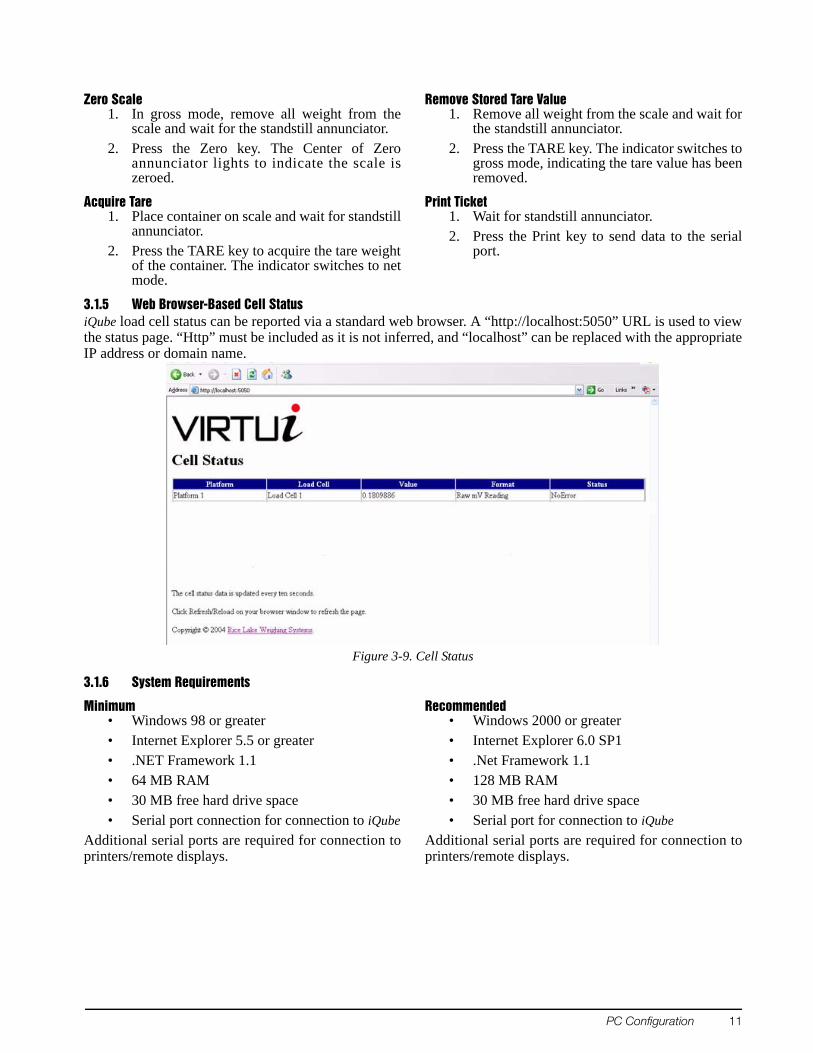
3.1.5 Web Browser-Based Cell StatusiQube load cell status can be reported via a standard web browser. A “http://localhost:5050” URL is used to viewthe status page. “Http” must be included as it is not inferred, and “localhost” can be replaced with the appropriateIP address or domain name.
Figure 3-9. Cell Status
3.1.6 System Requirements
Minimum• Windows 98 or greater• Internet Explorer 5.5 or greater• .NET Framework 1.1• 64 MB RAM• 30 MB free hard drive space• Serial port connection for connection to iQube
Additional serial ports are required for connection toprinters/remote displays.
Recommended• Windows 2000 or greater• Internet Explorer 6.0 SP1• .Net Framework 1.1• 128 MB RAM• 30 MB free hard drive space• Serial port for connection to iQube
Additional serial ports are required for connection toprinters/remote displays.
12 Tracer AVi Installation Manual
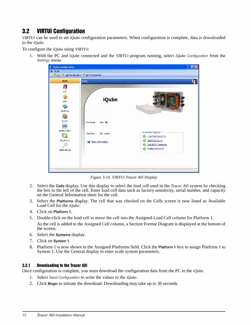
3.2 VIRTUI ConfigurationVIRTUi can be used to set iQube configuration parameters. When configuration is complete, data is downloadedto the iQube.To configure the iQube using VIRTUi:
1. With the PC and iQube connected and the VIRTUi program running, select iQube Configuration from theSettings menu.
Figure 3-10. VIRTUi Tracer AVi Display
2. Select the Cells display. Use this display to select the load cell used in the Tracer AVi system by checkingthe box to the left of the cell. Enter load cell data such as factory sensitivity, serial number, and capacityon the General Information sheet for the cell.
3. Select the Platforms display. The cell that was checked on the Cells screen is now listed as AvailableLoad Cell for the iQube.
4. Click on Platform 1.5. Double-click on the load cell to move the cell into the Assigned Load Cell column for Platform 1.
As the cell is added to the Assigned Cell column, a Section Format Diagram is displayed at the bottom ofthe screen.
6. Select the Systems display.7. Click on System 1.8. Platform 1 is now shown in the Assigned Platforms field. Click the Platform 1 box to assign Platform 1 to
System 1. Use the General display to enter scale system parameters.
3.2.1 Downloading to the Tracer AViOnce configuration is complete, you must download the configuration data from the PC to the iQube.
1. Select Send Configuration to write the values to the iQube. 2. Click Begin to initiate the download. Downloading may take up to 30 seconds.
Calibration 13
4.0 Calibration
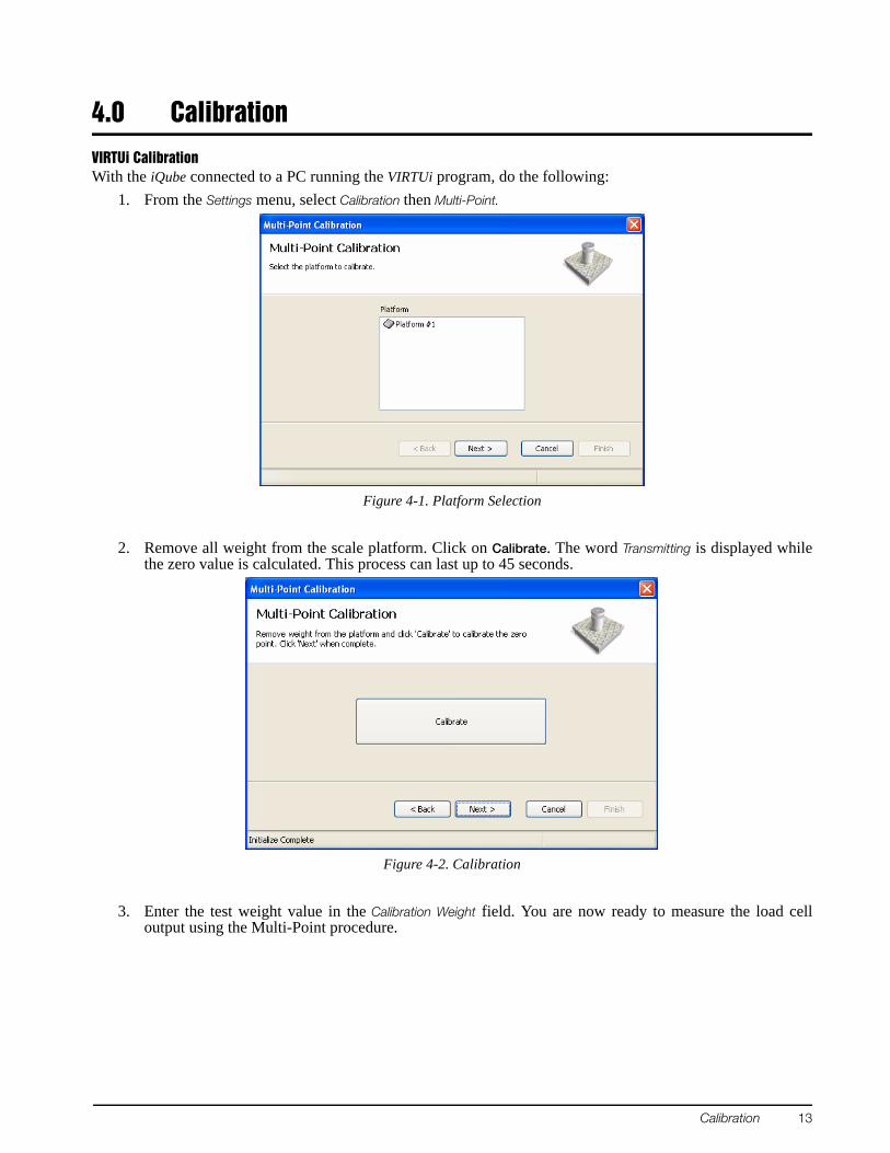
VIRTUi CalibrationWith the iQube connected to a PC running the VIRTUi program, do the following:
1. From the Settings menu, select Calibration then Multi-Point.
Figure 4-1. Platform Selection
2. Remove all weight from the scale platform. Click on Calibrate. The word Transmitting is displayed whilethe zero value is calculated. This process can last up to 45 seconds.
Figure 4-2. Calibration
3. Enter the test weight value in the Calibration Weight field. You are now ready to measure the load celloutput using the Multi-Point procedure.
14 Tracer AVi Installation Manual
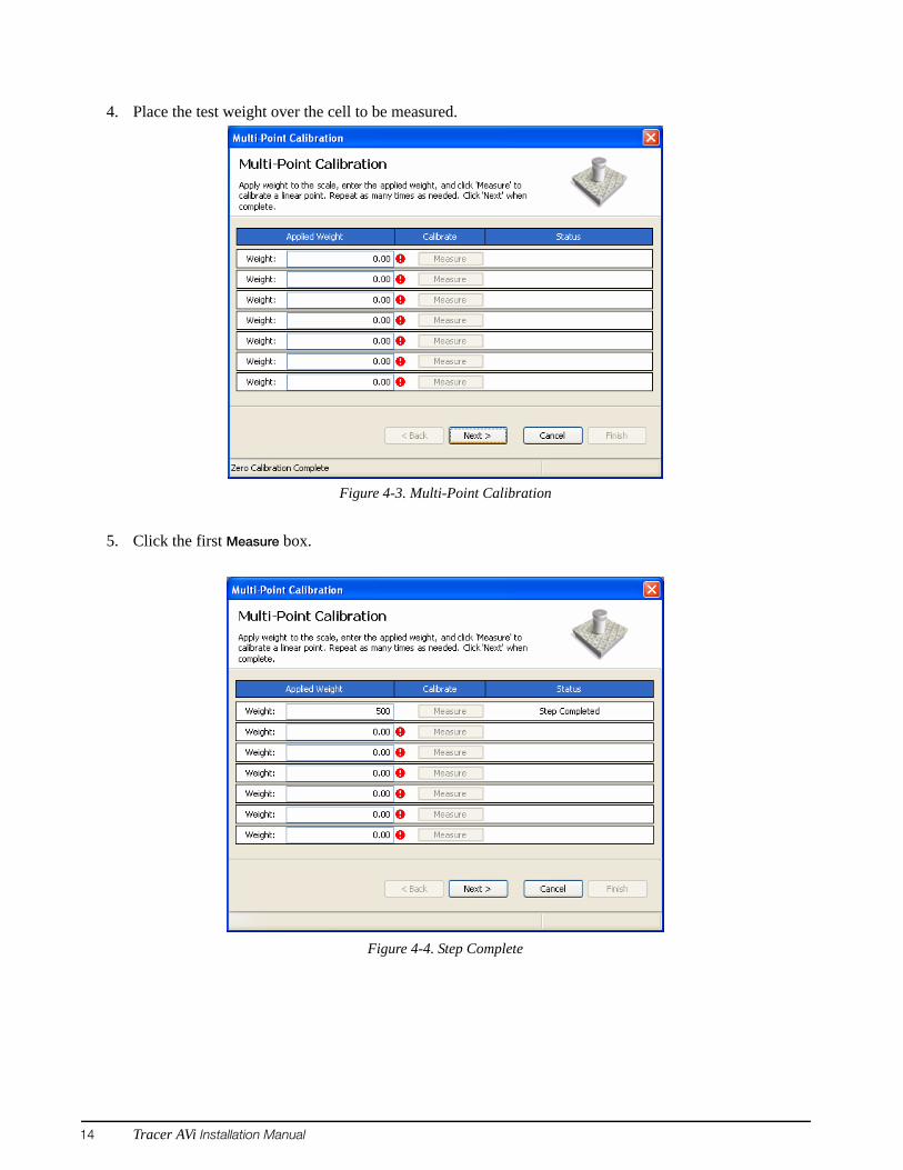
4. Place the test weight over the cell to be measured.
Figure 4-3. Multi-Point Calibration
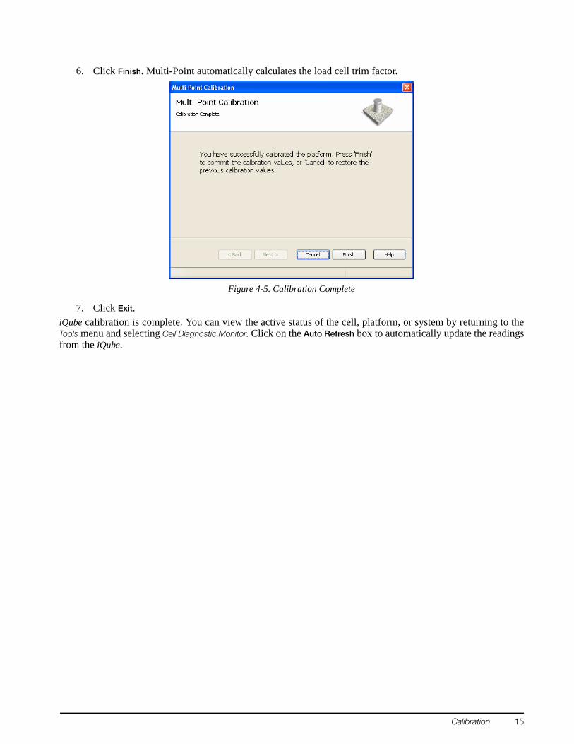
5. Click the first Measure box.
Figure 4-4. Step Complete
Calibration 15
6. Click Finish. Multi-Point automatically calculates the load cell trim factor.
Figure 4-5. Calibration Complete
7. Click Exit.iQube calibration is complete. You can view the active status of the cell, platform, or system by returning to theTools menu and selecting Cell Diagnostic Monitor. Click on the Auto Refresh box to automatically update the readingsfrom the iQube.
16 Tracer AVi Installation Manual
5.0 Diagnostics
5.1 Diagnostic TestsThe iQube provides a number of diagnostic tests, including boundary, weighing, and system tests.
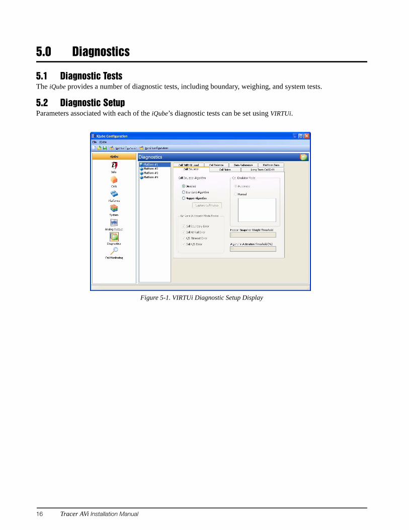
5.2 Diagnostic SetupParameters associated with each of the iQube’s diagnostic tests can be set using VIRTUi.
Figure 5-1. VIRTUi Diagnostic Setup Display
Specifications 17
6.0 Specifications
PowerAuto-Ranging Input 100-240 VAC, 50-60 Hz
1-channel, 350Ω load cell 75 mA (0.563 W)
A/D SpecificationsExcitation Voltage 4 VDC (+4V and ground, single-sided)Analog Signal Input Range –11.7 mV to +27.3 mVA/D Sample Rate 15 Hz
Serial CommunicationsJ4 Port Full duplex RS-232J6 Port Simplex RS-232J7 Port Simplex RS-232
EnvironmentalOperating Temperature–10 to +40°C (14 to 104°F)Storage Temperature –10 to +70°C (14 to 158°F)Humidity 0–95% relative humidity
Weight1.5 lbs
EnclosureEnclosure Dimensions 4.9” W x 3.0” H
Certifications and ApprovalsNTEPCoC Number 03-032Accuracy Class III/IIIL nmax: 10 000
•NAT
IONA
L CONFERENC
E•
ON
WE
IGH TS AN D M E A
SU
RES

18 Tracer AVi Installation Manual
Tracer AVi Limited WarrantyRice Lake Weighing Systems (RLWS) warrants that all RLWS equipment and systems properly installed by aDistributor or Original Equipment Manufacturer (OEM) will operate per written specifications as confirmed bythe Distributor/OEM and accepted by RLWS. All systems and components are warranted against defects inmaterials and workmanship for two years. RLWS warrants that the equipment sold hereunder will conform to the current written specifications authorizedby RLWS. RLWS warrants the equipment against faulty workmanship and defective materials. If any equipmentfails to conform to these warranties, RLWS will, at its option, repair or replace such goods returned within thewarranty period subject to the following conditions:
• Upon discovery by Buyer of such nonconformity, RLWS will be given prompt written notice with adetailed explanation of the alleged deficiencies.
• Individual electronic components returned to RLWS for warranty purposes must be packaged toprevent electrostatic discharge (ESD) damage in shipment. Packaging requirements are listed in apublication, Protecting Your Components From Static Damage in Shipment, available from RLWSEquipment Return Department.
• Examination of such equipment by RLWS confirms that the nonconformity actually exists, and wasnot caused by accident, misuse, neglect, alteration, improper installation, improper repair orimproper testing; RLWS shall be the sole judge of all alleged non-conformities.
• Such equipment has not been modified, altered, or changed by any person other than RLWS or itsduly authorized repair agents.
• RLWS will have a reasonable time to repair or replace the defective equipment. Buyer is responsiblefor shipping charges both ways.
• In no event will RLWS be responsible for travel time or on-location repairs, including assembly ordisassembly of equipment, nor will RLWS be liable for the cost of any repairs made by others.
THESE WARRANTIES EXCLUDE ALL OTHER WARRANTIES, EXPRESSED OR IMPLIED, INCLUDING WITHOUTLIMITATION WARRANTIES OF MERCHANTABILITY OR FITNESS FOR A PARTICULAR PURPOSE. NEITHERRLWS NOR DISTRIBUTOR WILL, IN ANY EVENT, BE LIABLE FOR INCIDENTAL OR CONSEQUENTIAL DAMAGES. RLWS AND BUYER AGREE THAT RLWS’ SOLE AND EXCLUSIVE LIABILITY HEREUNDER IS LIMITED TOREPAIR OR REPLACEMENT OF SUCH GOODS. IN ACCEPTING THIS WARRANTY, THE BUYER WAIVES ANY ANDALL OTHER CLAIMS TO WARRANTY.SHOULD THE SELLER BE OTHER THAN RLWS, THE BUYER AGREES TO LOOK ONLY TO THE SELLER FORWARRANTY CLAIMS.NO TERMS, CONDITIONS, UNDERSTANDING, OR AGREEMENTS PURPORTING TO MODIFY THE TERMS OF THISWARRANTY SHALL HAVE ANY LEGAL EFFECT UNLESS MADE IN WRITING AND SIGNED BY A CORPORATEOFFICER OF RLWS AND THE BUYER.
© 2007 Rice Lake Weighing Systems, Inc. Rice Lake, WI USA. All Rights Reserved.
RICE LAKE WEIGHING SYSTEMS • 230 WEST COLEMAN STREET • RICE LAKE, WISCONSIN 54868 • USA