Embed Size (px)
Citation preview

Track Roller Guidance SystemsTrack roller guidance systems
Track rollers, bolts, guideways Accessories

Track Roller Guidance SystemsTrack roller guidance systems
Track rollers, bolts, guidewaysAccessories

All data have been prepared with a great deal
of care and checked for their accuracy. However,
no liability can be assumed for any incorrect or
incomplete data. We reserve the right to make
technical modifications.
© Schaeffler Technologies AG & Co. KG
Issued: 2016, June
Reproduction in whole or in part without our
authorisation is prohibited.

Foreword
Track roller guidance systems LF are highly suitable, due to their lightweight construction, for applications in handling systemswhere low-noise running, high speeds and long travel distances are required together with low, uniform displacement resistance.
Economical modular concept In order to cover a wide range of requirements using standard components, the guidance systems are structured according toa modular concept. The system elements, namely carriages, composite guideways, track rollers and a precisely matched rangeof accessories can be combined to achieve designs that are precisely matched to the application.
Carriages Carriages LF are supplied in the form of:■ economical, lightweight hollow section carriages■ robust open carriages for high performance guidance systems
of a simple construction■ enclosed, compact carriages where guidance systems must
operate in contaminated environments■ non-locating bearing carriages for locating and non-locating
bearing applications with two guidance systems in a parallel arrangement
■ bogie carriages for curved tracks or closed oval and circular guidance systems.
Guideways Composite guideways are available as solid and hollow section guideways, with a support rail of high bending rigidity, as a half guideway, a curved guideway element or a flat design. Guideways with slots for toothed racks or toothed belts are also available.
Profiled track rollers Profiled track rollers without filling slots are used to guide the carriages and support the forces. These double row angular contact ball bearings have an outer ring with a gothic arch profile raceway, are sealed on both sides and are greased for life. They can support axial loads from both sides and high radial forces due to the thick-walled outer ring.
Accessories The spectrum of positive characteristics of our track roller guidance systems is completed by a comprehensive, precisely matched range of accessories for the system components.

4 LF 1 Schaeffler Technologies

Schaeffler Technologies LF 1 5
Page
Contents
Product index ......................................................................... 6
Tab index ............................................................................... 8
Track roller guidance systemsTechnical principles ........................................................... 10
Track roller guidance systems ............................................ 40
Track rollers, bolts, guideways ........................................... 66
Accessories ....................................................................... 104
Addresses .............................................................................. 124

6 LF 1 Schaeffler Technologies
Page
Product index
AB Lubrication and wiper unit for LFL-SF ....................................... 117
AB.LFR Cap wiper for LFCL................................................................... 118
AB.W Lubrication and wiper unit for guideways................................. 116
ABAL Side plate for LFL-SF................................................................ 119
ANS.LFS End plate for solid profile guideway......................................... 115
ANS.LFS..-C End plate for hollow section guideway..................................... 115
ANS.LFS..-F End plate for flat guideway...................................................... 115
ANS.LFS..-FH End plate for flat half guideway ............................................... 115
ANS.LFS..-NZZ End plate for guideway with slots ............................................ 115
KA.LFS..-C End cover for hollow section guideway .................................... 122
KA.LFS..-M End cover for profiled section guideway................................... 122
LEIS T-strip..................................................................................... 113
LFCL Hollow section carriage, clearance-free ................................... 56
LFDL..-B Bogie carriage, adjustable clearance ....................................... 64
LFDL..-SF Bogie carriage, clearance-free ................................................. 64
LFE Eccentric bolt.......................................................................... 88
LFE..-A1 Eccentric bolt with relubrication hole....................................... 88
LFKL..-SF Compact carriage, clearance-free ............................................ 58
LFKL..-E-SF Compact carriage, clearance-free,with heavy duty track rollers................................................. 58
LFKL..-EE-SF Compact carriage, clearance-free,with heavy duty track rollers................................................. 58
LFL..-SF Open carriage, clearance-free.................................................. 60
LFL..-E-SF Open carriage, clearance-free,with heavy duty track rollers................................................. 60
LFLL..-SF Non-locating bearing carriage, clearance-free.......................... 62
LFR..-2RS-RB Locating bearing profiled track roller ....................................... 84
LFR..-2Z Locating bearing profiled track roller ....................................... 84
LFRI Profiled track roller with extended inner ring............................ 86
LFR..-2RSR-NA Non-locating bearing track roller ............................................. 90
LFR..-2RSR-RNA Non-locating bearing profiled track roller without inner ring ..... 90

Schaeffler Technologies LF 1 7
PageLFS Guideway, solid profile ........................................................... 94
LFS..-C Guideway, hollow section profile ............................................ 94
LFS..-CE Guideway, hollow section profile ............................................ 94
LFS..-CEE Guideway, hollow section profile ............................................ 94
LFS..-E Guideway, solid profile ........................................................... 94
LFS..-EE Guideway, solid profile ........................................................... 94
LFS..-F Guideway, flat guideway ......................................................... 94
LFS..-FE Guideway, flat guideway ......................................................... 94
LFS..-FH Guideway, flat half guideway .................................................. 96
LFS..-FHE Guideway, flat half guideway .................................................. 96
LFS..-FHEE Guideway, flat half guideway .................................................. 96
LFS..-M Guideway, profiled section guideway ...................................... 98
LFS..-N Guideway with slots................................................................ 98
LFS..-NZZ Guideway with slots................................................................ 98
LFS..-RB Guideway, corrosion-resistant design ..................................... 94
LFSR..-ST Guideway, curved guideway element ...................................... 100
LFS..-OV../180-VBS Closed oval track with 180° arcs and guideway connectors...... 102
LFS..-OV../90-VBS Closed oval track with 90° arcs and guideway connectors........ 102
LFZ Concentric bolt ....................................................................... 88
LFZ..-A1 Concentric bolt with relubrication hole.................................... 88
MU T-nut ...................................................................................... 113
MU..POS Positionable T-nut .................................................................. 113
NAD Slot closing strip for LFS..-M.................................................... 123
PAH Stop for guideways ................................................................. 121
PASTP Stop for guideways ................................................................. 120
SHR T-bolts.................................................................................... 113
SPPR Fixing lug................................................................................ 113
VBS Guideway connector for guideways ......................................... 114

0001
AC17
0001
AC17
0001
AD16
0001
AD16
0001
A400
0001
A400
121
673
121
673

Technical principles
Track roller guidance systems■ With hollow section carriage■ With compact carriage■ With open carriage■ With non-locating bearing carriage■ With bogie carriage
Track rollers■ Locating bearing track roller■ Non-locating bearing track roller
Bolts■ Concentric■ Eccentric
Guideways■ With solid or hollow section profile■ Flat design■ With support rail■ With slots■ Half guideway■ Curved guideway element
Accessories
Addresses
0001
A282
0001
A282
0001
AC1B
0001
AC1B
121
670
121
670
0001
A401
0001
A401
0001
A402
0001
A402
0001
A281
0001
A281

Technical principlesLoad carrying capacity and rating lifeLubricationDesign of bearing arrangementsMountingAccuracyOrdering designationsOperating limits

Schaeffler Technologies LF 1 11
Page
Technical principles
Load carrying capacityand rating life
Permissible radial loads ............................................................ 12Permissible radial load under dynamic loading...................... 12Permissible radial load under static loading .......................... 13Fatigue limit load .................................................................. 13
Calculation of rating life............................................................. 13Rating life of track rollers....................................................... 14Operating life........................................................................ 16Static load safety factor......................................................... 17Minimum load....................................................................... 18Differences in raceway hardness ........................................... 18
Lubrication Lubrication of guideway raceways.............................................. 19Lubrication intervals ............................................................. 19Lubrication of track rollers..................................................... 19
Design of bearingarrangements
Requirements for the adjacent construction ............................... 21Shaft creep ........................................................................... 21Displacement force ............................................................... 21Location of carriages and guideways ..................................... 22Track roller guidance systemsin accordance with customer specifications........................... 22
Mounting Delivered condition ................................................................... 26
Mounting of guidance system with one guideway ....................... 26
Mounting of guidance system with two guideways...................... 27
Mounting of curved guideway elements and oval tracks ............. 27
Mounting of bogie carriages....................................................... 27
Accuracy Accuracy of guideways LFS......................................................... 30
Ordering example,ordering designation
Ready-to-fit systems .................................................................. 34
Closed oval tracks ..................................................................... 36Oval track with two 180° arcs ................................................ 36Oval track with four 90° arcs ................................................. 37
Individual components .............................................................. 38
Operating limits Operating temperature .............................................................. 39
Velocities .................................................................................. 39
Acceleration .............................................................................. 39
12 LF 1 Schaeffler Technologies
Load carrying capacity and rating life
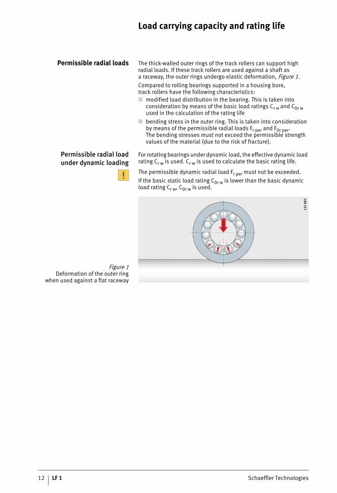
Permissible radial loads The thick-walled outer rings of the track rollers can support high radial loads. If these track rollers are used against a shaft asa raceway, the outer rings undergo elastic deformation, Figure 1.Compared to rolling bearings supported in a housing bore,track rollers have the following characteristics:■ modified load distribution in the bearing. This is taken into
consideration by means of the basic load ratings Cr w and C0r w used in the calculation of the rating life
■ bending stress in the outer ring. This is taken into consideration by means of the permissible radial loads Fr per and F0r per.The bending stresses must not exceed the permissible strength values of the material (due to the risk of fracture).
Permissible radial loadunder dynamic loading
For rotating bearings under dynamic load, the effective dynamic load rating Cr w is used. Cr w is used to calculate the basic rating life.
The permissible dynamic radial load Fr per must not be exceeded.If the basic static load rating C0r w is lower than the basic dynamic load rating Cr w, C0r w is used.
Figure 1Deformation of the outer ring
when used against a flat raceway
121
603
121
603
Schaeffler Technologies LF 1 13
Permissible radial loadunder static loading
For bearings under static load, when stationary or with only infrequent motion, the effective static load rating C0r w is used.C0r w is used to calculate the static load safety factor S0.At the same time, the permissible static radial load F0r per must not be exceeded.In addition to the permissible radial load of the bearing,the permissible radial load of the mating track must also be taken into consideration.The basic load ratings stated are valid only in conjunctionwith a shaft as a mating track that is hardened (at least 670 HV) and ground (Ra 0,3).
Fatigue limit load The fatigue limit load Cur w is defined as the load below which – under laboratory conditions – no fatigue occurs in the material.
Calculation of the rating life The general methods for calculating the rating life are:■ the basic rating life in accordance with DIN ISO 281■ the adjusted rating life in accordance with DIN ISO 281■ the expanded calculation of the adjusted reference rating life
in accordance with DIN ISO 281-4.These methods are described in Catalogue HR 1, Rolling Bearings,in the chapter Load carrying capacity and rating life.
14 LF 1 Schaeffler Technologies
Load carrying capacity and rating life
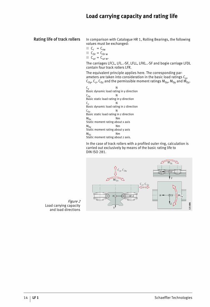
Rating life of track rollers In comparison with Catalogue HR 1, Rolling Bearings, the following values must be exchanged:
The carriages LFCL, LFL..-SF, LFLL, LFKL..-SF and bogie carriage LFDL contain four track rollers LFR.The equivalent principle applies here. The corresponding par-ameters are taken into consideration in the basic load ratings Cy, C0y, Cz, C0z and the permissible moment ratings M0x, M0y and M0z.
Cy NBasic dynamic load rating in y directionC0y NBasic static load rating in y directionCz NBasic dynamic load rating in z directionC0z NBasic static load rating in z directionM0x NmStatic moment rating about x axisM0y NmStatic moment rating about y axisM0z NmStatic moment rating about z axis.
In the case of track rollers with a profiled outer ring, calculation is carried out exclusively by means of the basic rating life to DIN ISO 281.
■ Cr = Crw■ C0r = C0r w■ Cur = Cur w.
Figure 2Load carrying capacity
and load directions 121
686
121
686

Schaeffler Technologies LF 1 15
Other formulae for calculatingthe basic rating life
Rating life for carriageswith four track rollers
Ls 105 mBasic rating life in metresDa mmRolling contact diameter of track roller, see dimension tablesCr w, Cy, Cz NEffective dynamic load ratingPr NEquivalent dynamic load (radial load)p –Ball: p = 3;needle roller (non-locating bearing track roller or carriage): p = 10/3Lh hBasic rating life in operating hoursH mSingle stroke length for reciprocating motionnosc min–1
Number of return strokes per minutev m/minMean travel velocityP N.Equivalent dynamic load in the corresponding load direction(for applications with combined loads, please contact us).

16 LF 1 Schaeffler Technologies
Load carrying capacity and rating life
Operating life The operating life is the life actually achieved by a rolling bearing.It may differ significantly from the calculated rating life.This may be due to wear or fatigue as a result of:■ deviations in the operating data■ insufficient or excessive operating clearance
(track roller, guideway)■ contamination■ inadequate lubrication■ operating temperature too high or too low■ reciprocating motion with very small stroke length,
which can lead to false brinelling■ high vibration load, leading to false brinelling■ very high shock loads (static overloading)■ prior damage during mounting.Due to the variety of mounting and operating conditions, the oper-ating life cannot be precisely calculated in advance. The most reliable way of arriving at a close estimate is by comparison with similar applications.
Schaeffler Technologies LF 1 17
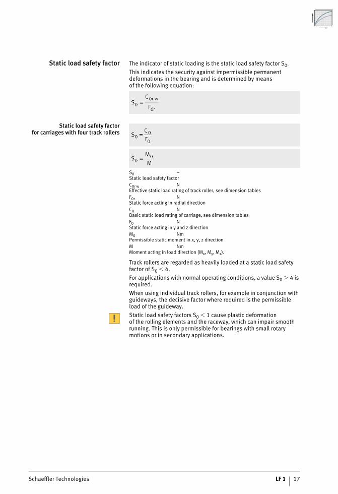
Static load safety factor The indicator of static loading is the static load safety factor S0.This indicates the security against impermissible permanent deformations in the bearing and is determined by meansof the following equation:
Static load safety factorfor carriages with four track rollers
S0 –Static load safety factorC0r w NEffective static load rating of track roller, see dimension tablesF0r NStatic force acting in radial directionC0 NBasic static load rating of carriage, see dimension tablesF0 NStatic force acting in y and z directionM0 NmPermissible static moment in x, y, z directionM NmMoment acting in load direction (Mx, My, Mz).
Track rollers are regarded as heavily loaded at a static load safety factor of S0 � 4.For applications with normal operating conditions, a value S0 � 4 is required.When using individual track rollers, for example in conjunction with guideways, the decisive factor where required is the permissible load of the guideway.Static load safety factors S0 � 1 cause plastic deformationof the rolling elements and the raceway, which can impair smooth running. This is only permissible for bearings with small rotary motions or in secondary applications.
18 LF 1 Schaeffler Technologies
Load carrying capacity and rating life
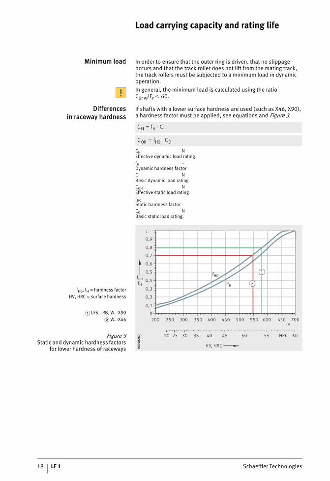
Minimum load In order to ensure that the outer ring is driven, that no slippage occurs and that the track roller does not lift from the mating track,the track rollers must be subjected to a minimum load in dynamic operation.In general, the minimum load is calculated using the ratio C0r w/Fr � 60.
Differencesin raceway hardness
If shafts with a lower surface hardness are used (such as X46, X90), a hardness factor must be applied, see equations and Figure 3.
CH NEffective dynamic load ratingfH –Dynamic hardness factorC NBasic dynamic load ratingC0H NEffective static load ratingfH0 –Static hardness factorC0 NBasic static load rating.
fH0, fH = hardness factorHV, HRC = surface hardness
� LFS..-RB, W..-X90� W..-X46
Figure 3Static and dynamic hardness factors
for lower hardness of raceways 0001
A260
0001
A260

Schaeffler Technologies LF 1 19
Lubrication
Lubricationof guideway raceways
The guideway raceways must be lubricated (even before first use). Lubrication can be carried out by means of lubrication and wiper units.These units are already integrated in the compact carriage LFKL..-SF. For carriages LFL..-SF and LFCL, the lubrication and wiper unit AB, see page 109, is available as an accessory.The guideway raceway is lubricated by an oil-soaked felt insert.Oil can be fed to the felt inserts via lubrication nipples in the end faces. At delivery, the felt inserts are already soaked with oil(H1 approval for the food industry), where relubrication is to be carried out an oil of viscosity � = 460 mm2/s is recommended.
Lubrication intervals The lubrication intervals for guideway raceways are dependenton the environmental influences. The cleaner the environment,the smaller the quantity of lubricant required. The time and quantity can only be determined precisely under operating conditions sinceit is not possible to determine all the influences by calculation.An observation period of adequate length must be allowed.Fretting corrosion is a consequence of inadequate lubrication and is visible as a reddish discolouration of the mating track or outer ring. Inadequate lubrication can lead to permanent system damage and therefore to failure. It must be ensured that the lubrication intervals are reduced accordingly in order to prevent fretting corrosion.In general, a thin film of oil should always be present on the shaft.
Lubrication of track rollers At delivery, track rollers LFR have an initial greasing of a high quality lithium soap grease.From LFR5204-16, the inner ring has a relubrication hole.Track rollers of smaller diameters are lubricated for life.

20 LF 1 Schaeffler Technologies
Lubrication
Further information on lubrication Further information can be found in Catalogue HR 1,Rolling Bearings, in the chapter Lubrication.
Figure 1Lubrication of guideway raceways 15
5 26
715
5 26
7

Schaeffler Technologies LF 1 21
Design of bearing arrangements
Requirementsfor the adjacent construction
The running accuracy of the linear guidance system is essentially dependent on the straightness, accuracy and rigidity of the mounting surfaces.The higher the requirements for accuracy and smooth runningof a track roller guidance system, the more attention must be paidto the geometrical and positional accuracy of the adjacent construc-tion. The adjacent surfaces should be flat and have parallel faces.For two guideways, we recommend a parallelism accordingto Figure 1.
Shaft creep Under unfavourable conditions, shaft creep of a few millimetres may occur in isolated cases. This creep may occur mainly in applications with high accelerations in conjunction with high alternating loads and guideways that are not completely supported. It may also be caused by an adjacent construction that is too soft.In such cases, shaft creep can be prevented by the use of end plates ANS.LFS, see dimension table page 115. They can be supplied already mounted.
Displacement force The displacement force is dependent on the preload, the lubrication and the particular application. It is therefore not possible to make generally valid statements.
Figure 1Parallelism of guideways 00
01A4
0300
01A4
03

22 LF 1 Schaeffler Technologies
Design of bearing arrangements
Location of carriages andguideways
If lateral loads are present, it is recommended that the guideways and carriages should be located against locating surfaces. In the case of guideways comprising multiple sections joined together,it is recommended that the guideways should be aligned by means of the shaft. If necessary, the shafts should be located on the adjacent construction by means of dowels.If two guideways are arranged in parallel, the first guideway should be clamped against a stop, Figure 1, page 21. The second guideway should then be aligned accordingly. Any gaps between the guideway and the adjacent construction should be filled with synthetic resin.
Track roller guidance systemsin accordance with customer
specifications
The INA track roller guidance systems with curved guideway elements can be used to achieve an extremely wide variety of applications, Figure 2 and Figure 3, page 23.If the arrangement required cannot be represented usingthe standard ordering designation, a customer drawing must be submitted with the enquiry.For arrangements with curved guideway elements, it is recommen-ded that the guideway connectors VBS should be used at the joints, see page 114. This gives considerably easier mounting.Standard oval tracks are always supplied with guideway connectors VBS, see page 102.
Figure 2Arrangement according
to customer requirements 121
552
121
552

Schaeffler Technologies LF 1 23
Figure 3Closed and open applications
with guidance systems includingcurved guideway elements 12
1 61
012
1 61
0
Design of bearing arrangements
24 LF 1 Schaeffler Technologies
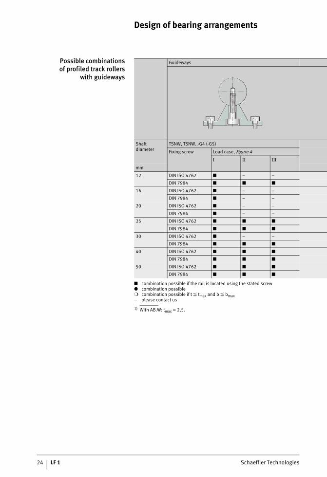
Possible combinationsof profiled track rollers
with guideways
1) With AB.W: tmax = 2,5.
Guideways
Shaftdiameter
TSNW, TSNW..-G4 (-G5)
Fixing screw Load case, Figure 4
I II III
mm
12 DIN ISO 4762 ■ – –
DIN 7984 ■ ■ ■
16 DIN ISO 4762 ■ – –
DIN 7984 ■ – –
20 DIN ISO 4762 ■ – –
DIN 7984 ■ – –
25 DIN ISO 4762 ■ ■ ■
DIN 7984 ■ ■ ■
30 DIN ISO 4762 ■ – –
DIN 7984 ■ ■ ■
40 DIN ISO 4762 ■ ■ ■
DIN 7984 ■ ■ ■
50 DIN ISO 4762 ■ ■ ■
DIN 7984 ■ ■ ■
■ combination possible if the rail is located using the stated screw● combination possible❍ combination possible if t � tmax and b � bmax– please contact us

Schaeffler Technologies LF 1 25
For the combination, take account of:■ the static load safety factor S0, see page 17■ the load cases, Figure 4■ a shaft hardness of 670 HV.
TSUW TSSW TSMW
tmax bmax Load case, Figure 4 tmax Load case, Figure 4 Load case, Figure 4
I II III I II III I II III
mm mm mm1)
5 5 ● ❍1) – – – – – – –
– – ● – – – – – – – – –
– – ● – – – ● – – ● – –
10 12 ● ● ❍ 36 ● ● ● ● ● ●
12 16 ● ● ❍ 42 ● ● ● ● ● ●
10 – ● ● ❍ 50 ● ● ● – – –
13 – ● ● ❍ 70 ● ● ● – – –
S0 = C0w/P0
Figure 4Load cases I, II and III 12
1 36
412
1 36
4

26 LF 1 Schaeffler Technologies
Mounting
Delivered condition Carriages are delivered with the track rollers fitted. All the bolts are tightened to the required tightening torque.
Carriages For carriages, this gives:■ hollow section carriage LFCL;
clearance-free, with mounting of accessories as necessary■ compact carriage LFKL..-SF;
clearance-free, with mounting of lubrication and wiper unitas necessary
■ non-locating bearing carriage LFLL..-SF;clearance-free, with mounting of accessories as necessary
■ open carriage LFL..-SF;clearance-free, with mounting of accessories as necessary
■ bogie carriage LFDL..-SF (-B);LFDL..-SF clearance-free, with mounting of accessoriesas necessary. In the case of LFDL..-B, the clearance must be setby means of eccentrics.
Mounting of guidance systemwith one guideway
Mounting of guidance system with one guideway:■ Place the guideway on the adjacent construction and screw
mount finger tight.■ Align the guideway; if necessary, clamp the shaft against the
locating edge and screw mount firmly, observing the tightening torques.
■ Clearance-free carriages: slide the carriage onto the guideway.■ Carriages with adjustable clearance: if lateral load is present,
ensure that the principal load is supported by the concentric bolts.
■ Position and screw mount the adjacent construction.
Schaeffler Technologies LF 1 27
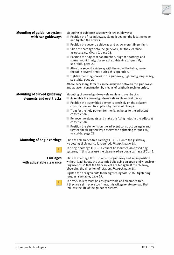
Mounting of guidance systemwith two guideways
Mounting of guidance system with two guideways:■ Position the first guideway, clamp it against the locating edge
and tighten the screws.■ Position the second guideway and screw mount finger tight.■ Slide the carriage onto the guideway, set the clearance
as necessary, Figure 2, page 28.■ Position the adjacent construction, align the carriage and
screw mount firmly; observe the tightening torques MA,see table, page 29.
■ Align the second guideway with the aid of the table, movethe table several times during this operation.
■ Tighten the fixing screws in the guideway; tightening torques MA, see table, page 29.
Where necessary, form fit can be achieved between the guideways and adjacent construction by means of synthetic resin or strips.
Mounting of curved guidewayelements and oval tracks
Mounting of curved guideway elements and oval tracks:■ Assemble the curved guideway elements or oval tracks.■ Position the assembled elements precisely on the adjacent
construction and fix in place by means of clamps.■ Transfer the hole pattern for the fixing holes to the adjacent
construction.■ Remove the elements and make the fixing holes in the adjacent
construction.■ Position the elements on the adjacent construction again and
tighten the fixing screws; observe the tightening torques MA,see table, page 29.
Mounting of bogie carriage Slide the clearance-free carriage LFDL..-SF onto the guideway.No setting of clearance is required, Figure 1, page 28.The bogie carriage LFDL..-SF cannot be mounted on closed ring systems, in this case use the clearance-free bogie carriage LFDL..-B.
Carriageswith adjustable clearance
Slide the carriage LFDL..-B onto the guideway and set in position without load. Rotate the eccentric bolts using an open-end wrench or ring wrench so that the track rollers are set against the raceway, observing the direction of rotation, Figure 2, page 28.Tighten the hexagon nuts to the tightening torque MA; tightening torques, see table, page 29.The track rollers must be easily movable and clearance-free.If they are set in place too firmly, this will generate preload that reduces the life of the guidance system.

28 LF 1 Schaeffler Technologies
Mounting
Inspection Check the adjustment. The guidance system is correctly adjustedif, when the carriages are moved, all the track rollers rotate andthe carriages can be moved easily.The concentric bolts are tightened to the necessary tightening torque, the eccentric bolts are tightened finger tight. When setting the preload, these must be tightened to the tightening torque MA, see table Tightening torques for track roller bolts, page 29.
Figure 1Clearance-free carriage LFDL..-SF
121
626A
121
626A
Figure 2Carriage with adjustable
clearance LFDL..-B15
6 54
1A15
6 54
1A

Schaeffler Technologies LF 1 29
Tightening torquesfor track roller bolts
Tightening torquesfor screws in carriage
according to DIN ISO 4762-8.8
Tightening torquesfor screws in guideways LFS
according to DIN ISO 4762-8.8 orDIN 7984-8.8
Track roller,profiled track roller
Bolt Tightening torqueMA
Standard (-2Z) RB (-2RSR)
Nm Nm
LFR50/5-4 M4 2,5 2,5
LFR50/5-6 M4 2,5 2,5
LFR50/8-6 M8 15 12
LFR5201-10 M10 40 23
LFR5301-10 M10 40 23
LFR5302-10 M12 70 39
LFR5201-12 M10 40 23
LFR5204-16 M16�1,5 100 75
LFR5206-20 M20�1,5 200 100
LFR5206-25 M20�1,5 200 100
LFR5207-30 M24�1,5 300 150
LFR5208-40 M30�1,5 600 310
LFR5308-50 M30�1,5 800 410
Screw Tightening torqueMA
Nm
M5 5,8
M6 9,9
M8 24
M10 48
M12 83
Screw Tightening torqueMA
Nm
M5 5,8
M6 9,9
M8 24
M10 48
M12 83

30 LF 1 Schaeffler Technologies
Accuracy
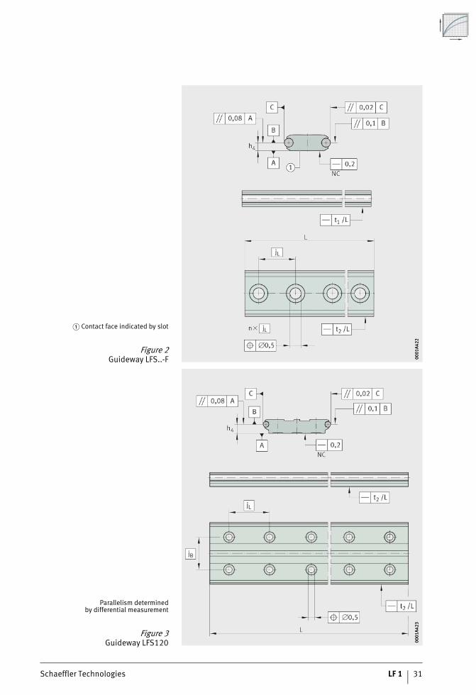
Accuracy of guideways LFS Data on the straightness, parallelism (differential measurement), length and positional tolerances of guideways are given in the following tables and figures, Figure 1 to Figure 5, page 32.The guideways are precision straightened and the tolerances are better than DIN EN 12020.
Length tolerance
Straightness tolerancefor guideways
Length Tolerance
L
mm mm
Single-piece guideways L � 1 000 �2
1 000 � L � 2 000 �3
2 000 � L � 4 000 �4
4 000 � L �5
Multi-piece guideways Total length L �0,1%
Length of guideway Tolerance
t1(contact face)
t2(lateral)
mm mm
L � 1 000 0,5 0,2
1 000 � L � 2 000 1 0,3
2 000 � L � 3 000 1,5 0,4
3 000 � L � 4 000 2 0,5
4 000 � L � 5 000 2,5 0,6
5 000 � L � 6 000 3 0,7
6 000 � L � 7 000 3,5 0,8
7 000 � L � 8 000 4 0,9
Figure 1Tolerances for guideways
LFS, LFS..-C, LFS..-NZZ, LFSR..-ST 0001
A419
0001
A419
Schaeffler Technologies LF 1 31
� Contact face indicated by slot
Figure 2Guideway LFS..-F 00
01A4
2200
01A4
22
Parallelism determinedby differential measurement
Figure 3Guideway LFS120 00
01A4
2300
01A4
23

32 LF 1 Schaeffler Technologies
Accuracy
Parallelism determinedby differential measurement
Figure 4Guideway LFS..-M 00
01A4
2800
01A4
28
� Contact face indicated by slot
Figure 5Guideway LFS..-FH 00
01A4
0400
01A4
04

Schaeffler Technologies LF 1 33
Tolerances for H2 and h4, see table, Figure 6 and Figure 7.Tolerances for H2 and h4 Guideway Tolerance for
H2 h4
mm mm
LFS20
+0,3
–0,1
LFS25 –0,1
LFS25-M �0,25
LFS32 +0,2
LFS32-C +0,2
LFS32-N +0,2
LFS32-F +0,1
LFS32-M �0,25
LFS32-FH +0,1
LFS42-C +0,2
LFS42-F +0,1
LFS52 +0,2
LFS52-C +0,2
LFS52-NZZ +0,2
LFS52-F +0,1
LFS52-M +0,5
LFS52-FH +0,1
LFS86-C +0,25
LFS120 +0,2
Tolerance for H2 = +0,3 mm
Figure 6Reference dimension for accuracy,
dimension H2
121
270
121
270
Figure 7Reference dimension for accuracy,
dimension h4
121
345
121
345
34 LF 1 Schaeffler Technologies
Ordering example, ordering designation
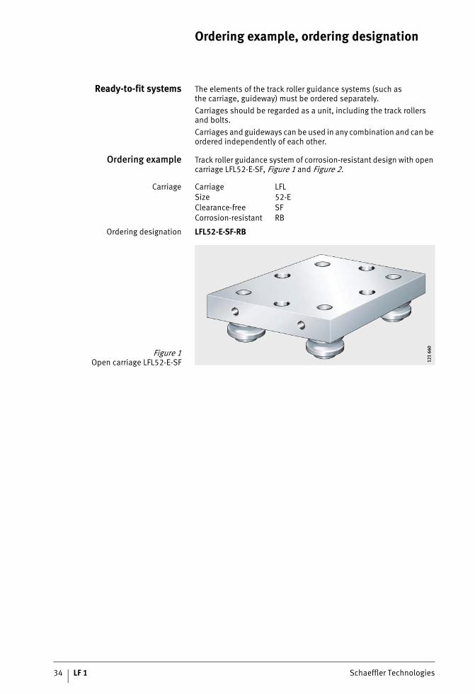
Ready-to-fit systems The elements of the track roller guidance systems (such asthe carriage, guideway) must be ordered separately.Carriages should be regarded as a unit, including the track rollers and bolts.Carriages and guideways can be used in any combination and can be ordered independently of each other.
Ordering example Track roller guidance system of corrosion-resistant design with open carriage LFL52-E-SF, Figure 1 and Figure 2.
Carriage
Ordering designation LFL52-E-SF-RB
Carriage LFLSize 52-EClearance-free SFCorrosion-resistant RB
Figure 1Open carriage LFL52-E-SF 12
1 66
012
1 66
0
Schaeffler Technologies LF 1 35
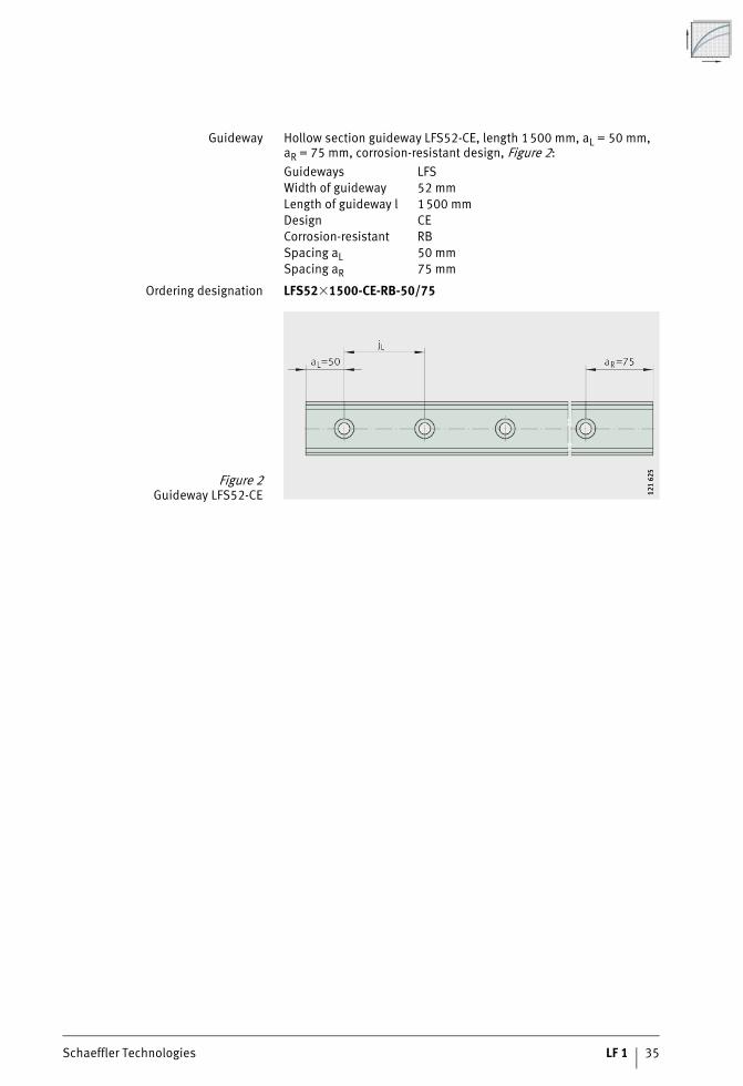
Guideway Hollow section guideway LFS52-CE, length 1500 mm, aL = 50 mm, aR = 75 mm, corrosion-resistant design, Figure 2:
Ordering designation LFS52�1500-CE-RB-50/75
Guideways LFSWidth of guideway 52 mmLength of guideway l 1500 mmDesign CECorrosion-resistant RBSpacing aL 50 mmSpacing aR 75 mm
Figure 2Guideway LFS52-CE 12
1 62
512
1 62
5
36 LF 1 Schaeffler Technologies
Ordering example, ordering designation
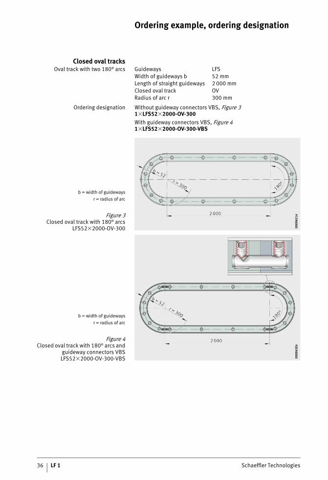
Closed oval tracksOval track with two 180° arcs
Ordering designation Without guideway connectors VBS, Figure 31�LFS52�2000-OV-300With guideway connectors VBS, Figure 41�LFS52�2000-OV-300-VBS
Guideways LFSWidth of guideways b 52 mmLength of straight guideways 2 000 mmClosed oval track OVRadius of arc r 300 mm
b = width of guidewaysr = radius of arc
Figure 3Closed oval track with 180° arcs
LFS52�2000-OV-300 0009
6514
0009
6514
b = width of guidewaysr = radius of arc
Figure 4Closed oval track with 180° arcs and
guideway connectors VBSLFS52�2000-OV-300-VBS 00
0965
E400
0965
E4

Schaeffler Technologies LF 1 37
Oval track with four 90° arcs
Ordering designation Without guideway connectors VBS, Figure 51�LFS52�2000�3000-OV-300With guideway connectors VBS, Figure 61�LFS52�2000�3000-OV-300-VBS
Guideways LFSWidth of guideways b 52 mmLength of straight guideways
1st straight guideway 2 000 mm2nd straight guideway 3 000 mm
Closed oval track OVRadius of arc r 300 mm
b = width of guidewaysr = radius of arc
Figure 5Closed oval track with 90° arcs
LFS52�2000�3000-OV-300 0009
6698
0009
6698
b = width of guidewaysr = radius of arc
Figure 6Closed oval track with 90° arcs and
guideway connectors VBSLFS52�2000�3000-OV-300-VBS 00
0966
EB00
0966
EB

38 LF 1 Schaeffler Technologies
Ordering example, ordering designation
Individual components In order to achieve versatile user designs, it is also possible to order individual components of the ready-to-fit systems;example, Figure 7.
Track roller
Ordering designation LFR50/8-6-2RS-RB
Bolt
Ordering designation LFZ8-RB
Cap wiper
Ordering designation AB.LFR50/8
Series LFRSize 50/8-6Sealing 2RSCorrosion-resistant RB, Figure 7
Series LFConcentric ZSize 8Corrosion-resistant RB, Figure 7
Series AB.LFRSize 50/8, Figure 7
� Track roller� Bolt, concentric
� Cap wiper
Figure 7Track roller, bolt, wiper 00
0999
6100
0999
61

Schaeffler Technologies LF 1 39
Operating limits
Operating temperature Track roller guidance systems can be used at a temperature from –20 °C to +80 °C. For applications below –20 °C and above +80 °C, please contact us.The area of application is restricted by the lubricant, the plastics used and the composite materials.
Velocities The maximum possible speed of track roller guidance systems is 10 m/s. Higher speeds may be possible by agreement.
Acceleration When using track roller guidance systems, accelerations of up to 50 m/s2 can be achieved.
Track roller guidance systemsWith hollow section carriageWith compact carriageWith open carriageWith non-locating bearing carriageWith bogie carriage

Schaeffler Technologies LF 1 41
Page
Track roller guidance systems
Matrix Matrix for preselection of track roller guidance systems.............. 42
Product overview Track roller guidance systems .................................................... 44
Features Track roller guidance systemsWith hollow section carriage ................................................. 46With compact carriage........................................................... 48With open carriage................................................................ 50With non-locating bearing carriage ........................................ 52With bogie carriage ............................................................... 54
Dimension tables Track roller guidance systemsWith hollow section carriage ................................................. 56With compact carriage........................................................... 58With open carriage................................................................ 60With non-locating bearing carriage ........................................ 62With bogie carriage ............................................................... 64

42 LF 1 Schaeffler Technologies
Matrix for preselectionof track roller guidance systems
1) The guideway LFS..-M can only be combined with carriages with adjustableclearance. If carriages LFCL and LFKL..-SF are to be used, please contact usin advance.
Track roller guidance systemswith
Width of guideways Corrosion-resistant
20 25 32 42 52 86
Hollow section carriageLFCL
– ● – ● – ● ■
Compact carriage LFKL..-SF
● ● ● – ● – ■
Open carriage LFL..-SF
● – ● – ● – ■
Non-locating bearing carriage LFLL..-SF
– – ● – ● – ■
Bogie carriage LFDL..-SFLFDL..-B
– – ● – ● – ■
● available sizes■ possible

Schaeffler Technologies LF 1 43
Special features of guidance systems Sizes Basic dimensions of guidance systems, dimensions, Figure 1 Description
LFS (-C, -CE, -CEE,-E, -EE, -NZZ, -OV), LFSR..-ST
LFS..-F (-FE) LFS..-M1)
H B L H B L H B L see page
■ economical■ low mass■ high moment load carrying capacity MX
254286
32,13959
80116190
110150235
–33,9–
80116190
110150235
63,1––
80116190
110150235
46
■ closed series■ protected track rollers■ integrated lubrication unit
2025325252-E52-EE
222535,554,360,460,4
56658613
145155
6985
112136186205
––25,538,244,344,3
566586
130145155
6985
112136186205
–56
–118,9125125
566586
130145155
6985
112136186205
48
■ very robust■ simple construction
20325252-E
2235,554,360,4
5580
120135
5090
100150
–25,538,244,3
5580
120135
5090
100150
–81,5
118,9125
5580
120135
5090
100150
50
■ locating and non-locating bearing arrangement
■ compensation of skewingin the adjacent constructionup to �1 mm
3252
35,554,3
80120
90100
25,538,2
80120
90100
81,5118,9
80120
90100
52
■ oval track guidance systemsfor unlimited stroke length
32-B32-SF 52-B52-SF
44,244,266,160,1
8080
120120
100100150150
34,234,25050
8080
120120
100100150150
90,290,2
130,7130,7
8080
120120
100100150150
54
Figure 1Dimensions H, B, L 12
1 65
112
1 65
1

44 LF 1 Schaeffler Technologies
Product overview Track roller guidance systems
With hollow section carriageClearance-free
LFCL
121
469
121
469
With compact carriageClearance-free
LFKL..-SF
121
471
121
471
With open carriageClearance-free
LFL..-SF
121
470
121
470

Schaeffler Technologies LF 1 45
With non-locating bearingcarriage
Clearance-free
LFLL..-SF
121
597
121
597
With bogie carriageConcentric and eccentric bolts,
adjustable clearance
LFDL..-B
121
627
121
627
Concentric boltsclearance-free
LFDL..-SF
121
626
121
626

46 LF 1 Schaeffler Technologies
Track roller guidance systems
Features Track roller guidance systems are available with a hollow section carriage, compact carriage, open carriage, non-locating bearing carriage or bogie carriage.
Track roller guidance systemwith hollow section carriage
The economical series LFCL is characterised in particular by its low mass and its high moment load carrying capacity Mx. In addition, more individual design of the adjacent construction is possible by means of four T-bolts that can be moved in a longitudinal direction.A carriage comprises a carriage plate made from anodised aluminium, four concentric bolts, four track rollers, two end covers for the hollow sections and four T-nuts that can be used forthe adjacent construction, Figure 1. The track rollers and end covers are already fitted.
� T-nut� End cover
� Carriage plate� Track roller
� Concentric bolt
Figure 1Hollow section carriage 12
1 33
812
1 33
8

Schaeffler Technologies LF 1 47
Preload and clearance The carriages run clearance-free on all INA guideways, see page 42,and can be combined with all guideways of the relevant size, but not with the curved guideway elements LFSR. Due to the highly accurate guideways, it is not necessary to set the clearance.
Sealing and lubrication The track rollers have gap seals on both sides, are greased for life and are therefore maintenance-free.The raceways can be lubricated using cap wipers AB.LFR. Their fixing screws pass into the screw mounting channels of the carriage plate.
Corrosion-resistant design All steel parts, the inner and outer rings of the track rollers andthe bolts, washers and nuts are made from corrosion-resistant steel. The rolling elements are protected against corrosion by the grease.Corrosion-resistant designs have the suffix RB.
Further information Further information is given on the following pages:■ dimension table, see page 56■ track rollers, see page 68■ guideways, see page 76■ accessories, see page 106.

48 LF 1 Schaeffler Technologies
Track roller guidance systems
Track roller guidance systemwith compact carriage
The closed compact carriage LFKL..-SF gives a simple meansof achieving track roller guidance systems for operation in contami-nated environments. The track rollers are protected against contamination by the closed design. It has two integrated lubrication units for lubrication of the raceways.A carriage comprises a saddle plate made from anodised, profiled aluminium, four concentric bolts, four track rollers, two sealing strips and two lubrication and wiper units, Figure 2. The track rollers are already fitted, the sealing strips as well as the lubrication and wiper units are included loose in the delivery.
� Sealing strip� Lubrication and wiper unit
� Track roller� Concentric bolt
� Saddle plate
Figure 2Compact carriage 12
1 31
212
1 31
2

Schaeffler Technologies LF 1 49
Preload and clearance The carriages run clearance-free on all INA guideways, see page 42,and can be combined with all guideways of the relevant size, but not with the curved guideway elements LFSR. Due to the highly accurate guideways, it is not necessary to set the clearance.
Sealing and lubrication The track rollers have gap seals on both sides, are greased for life and are therefore maintenance-free.For lubrication of the raceways, the lubrication and wiper units have oil-soaked felt inserts that can be replenished with oil via lubrication nipples. In combination with the sealing strips (gap seals),these units protect the compact carriage on all sides against contamination.
Corrosion-resistant design All steel parts, the inner and outer rings of the track rollers andthe bolts, washers and nuts are made from corrosion-resistant steel. The rolling elements are protected against corrosion by the grease.Corrosion-resistant designs have the suffix RB.
Further information Further information is given on the following pages:■ dimension table, see page 58■ track rollers, see page 68■ guideways, see page 76■ accessories, see page 106.

50 LF 1 Schaeffler Technologies
Track roller guidance systems
Track roller guidance systemwith open carriage
The robust, open carriage LFL..-SF is suitable where high performance linear guidance systems of a simple construction are required.A carriage comprises a carriage plate made from anodised aluminium, four screws and four track rollers, Figure 3. The track rollers are already fitted.
� Carriage plate� Screws
� Track roller
Figure 3Open carriage 12
1 66
212
1 66
2

Schaeffler Technologies LF 1 51
Preload and clearance The carriages run clearance-free on all INA guideways, see page 42,and can be combined with all guideways of the relevant size, but not with the curved guideway elements LFSR. Due to the highly accurate guideways, it is not necessary to set the clearance.
Sealing and lubrication The track rollers have gap seals on both sides, are greased for life and are therefore maintenance-free.The raceways can be lubricated by means of lubrication and wiper units AB, see page 106. Their oil-soaked felt inserts can be replen-ished with oil via lubrication nipples. In combination with side plates ABAL, these units seal the end faces and longitudinal sidesof the open carriage, see page 107.
Corrosion-resistant design All steel parts, the inner and outer rings of the track rollers andthe screws, washers and nuts are made from corrosion-resistant steel. The rolling elements are protected against corrosionby the grease.Corrosion-resistant designs have the suffix RB.
Further information Further information is given on the following pages:■ dimension table, see page 60■ track rollers, see page 68■ guideways, see page 76■ accessories, see page 106.
52 LF 1 Schaeffler Technologies
Track roller guidance systems
Track roller guidance systemwith non-locating bearing
carriage
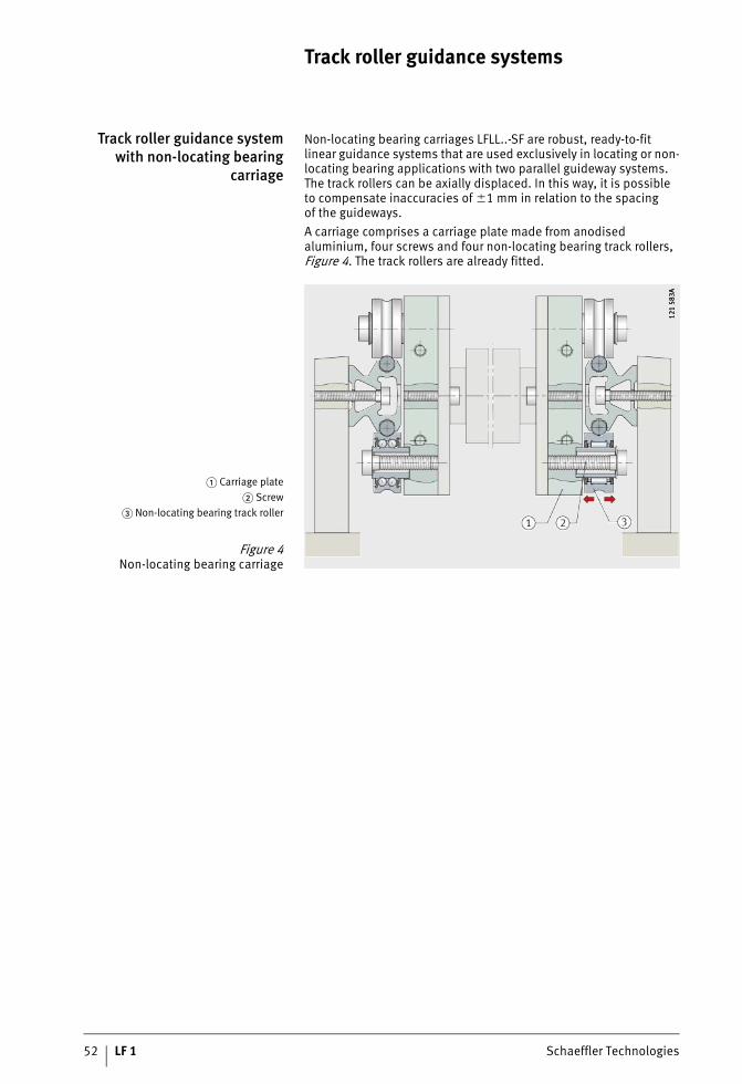
Non-locating bearing carriages LFLL..-SF are robust, ready-to-fit linear guidance systems that are used exclusively in locating or non-locating bearing applications with two parallel guideway systems. The track rollers can be axially displaced. In this way, it is possibleto compensate inaccuracies of �1 mm in relation to the spacingof the guideways.A carriage comprises a carriage plate made from anodised aluminium, four screws and four non-locating bearing track rollers, Figure 4. The track rollers are already fitted.
� Carriage plate� Screw
� Non-locating bearing track roller
Figure 4Non-locating bearing carriage
121
583A
121
583A

Schaeffler Technologies LF 1 53
Preload and clearance The carriages run clearance-free on all INA guideways, see page 42,and can be combined with all guideways of the relevant size, but not with the curved guideway elements LFSR. Due to the highly accurate guideways, it is not necessary to set the clearance.
Sealing and lubrication The track rollers have gap seals on both sides, are greased for life and are therefore maintenance-free.The contact zone between the raceways and track rollers must be lubricated via the shaft.
Corrosion-resistant design All steel parts, the inner and outer rings of the track rollers andthe screws, washers and nuts are made from corrosion-resistant steel.The rolling elements are protected against corrosion by the grease.Corrosion-resistant designs have the suffix RB (available by agreement only).Non-locating bearing carriages must never be used on their own but only ever in combination with locating bearing carriages.The track rollers can support loads in a radial direction only.
Further information Further information is given on the following pages:■ dimension table, see page 62■ track rollers, see page 68■ guideways, see page 76■ accessories, see page 106.

54 LF 1 Schaeffler Technologies
Track roller guidance systems
Track roller guidance systemwith bogie carriage
Bogie carriages LFDL..-B and LFDL..-SF can be used in combination with curved guideway elements LFSR..-ST to achieve almost any variant of oval and circular track guidance systems. The straight guideway elements are precisely matched to the arc.The carriages LFDL..-B and LFDL..-SF comprise a steel carriage plate, two aluminium swivel brackets (supported axially and radiallyby rolling bearings). In the case of LFDL..-B, the preload of the four profiled track rollers can be set by means of two concentric and two eccentric bolts. In the case of LFDL..-SF, the preload is already preset to the optimum value by means of four concentric bolts, Figure 5.LFDL..-SF cannot be mounted on closed curved guideway systems.
� Carriage plate� Bracket
� Track roller� Concentric bolt
Figure 5Bogie carriage 12
1 66
412
1 66
4

Schaeffler Technologies LF 1 55
Sealing and lubrication The track rollers have gap seals on both sides, are greased for life and are therefore maintenance-free.The contact zone between the raceways and track rollers must be lubricated via the shaft.
Corrosion-resistant design All steel parts, the inner and outer rings of the track rollers andthe bolts, washers and nuts are made from corrosion-resistant steel. The rolling elements are protected against corrosion by the grease.Corrosion-resistant designs have the suffix RB (available by agreement only).The adjustable carriage LFDL..-B must be used in combinationwith a 360° guideway.
Further information Further information is given on the following pages:■ dimension table, see page 64■ track rollers, see page 68■ guideways, see page 76■ accessories, see page 106.
56 LF 1 Schaeffler Technologies
Track roller guidance systemwith hollow section carriage
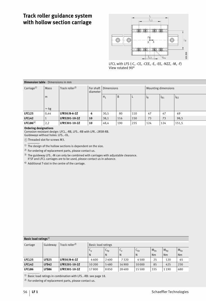
LFCL with LFS (-C, -CE, -CEE, -E, -EE, -NZZ, -M, -F)View rotated 90°
121
253
121
253
Ordering designationsCorrosion-resistant design: LFCL..-RB, LFS..-RB with LFR..-2RSR-RB.Guideways without holes: LFS..-OL.� Threaded slot for screws M3.
1) The design of the hollow sections is dependent on the size.2) For ordering of replacement parts, please contact us.3) The guideway LFS..-M can only be combined with carriages with adjustable clearance.
If SF and LFCL carriages are to be used, please contact us in advance.4) Additional T-slot in the centre of the carriage.
1) Basic load ratings in combination with LFS..-RB: see page 18.2) For ordering of replacement parts, please contact us.
Dimension table · Dimensions in mm
Carriage1) Mass Track roller2) For shaft diameter
Dimensions Mounting dimensions
m H1 B L JB JB1 JB2
� kg
LFCL25 0,44 LFR50/8-6-2Z 6 30,5 80 110 47 47 69
LFCL42 1 LFR5201-10-2Z 10 38,1 116 150 73 73 98,5
LFCL864) 2,2 LFR5301-10-2Z 10 48,4 190 235 124 124 151,5
Basic load ratings1)
Carriage Guideway Track roller2) Basic load ratings
Cy C0y Cz C0z M0x M0y M0z
N N N N Nm Nm Nm
LFCL25 LFS25 LFR50/8-6-2Z 4 600 2 400 7 320 4 500 25 120 65
LFCL42 LFS42 LFR5201-10-2Z 10 200 5 480 16 900 10 000 85 425 230
LFCL86 LFS86 LFR5301-10-2Z 17 800 8 850 28 400 15 500 335 1 190 680
Schaeffler Technologies LF 1 57
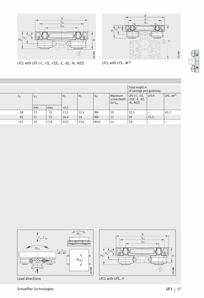
LFCL with LFS (-C, -CE, -CEE, -E, -EE, -N, -NZZ)
121
252
121
252
LFCL with LFS..-M3)
121
585
121
585
Total height Hof carriage and guideway
JL1 JL3 H2 H3 G4 Maximumscrew depthfor G4
LFS (-C, -CE,-CEE, -E, -EE,-N, -NZZ)
LFS-F LFS..-M3)
min. max. +0,3
58 13 32 21,5 15,4 M6 10 32,1 – 63,1
85 15 55 26,4 18 M8 12 39 33,9 –
155 18 119 33,9 23,4 M10 14 59 – –
Load directions LFCL with LFS..-F
121
650
121
650
121
586
121
586
58 LF 1 Schaeffler Technologies
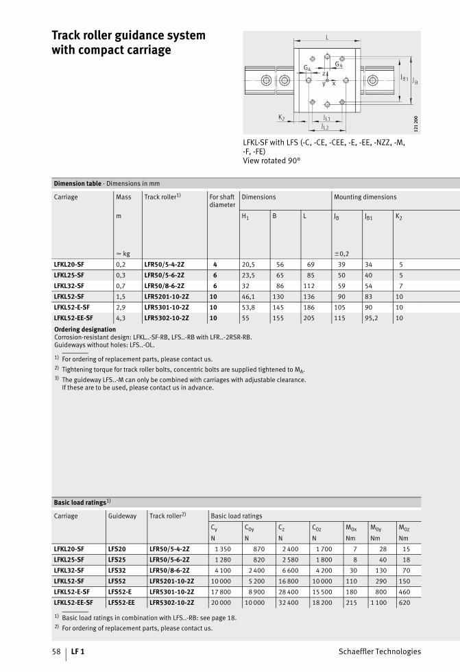
Track roller guidance systemwith compact carriage
LFKL-SF with LFS (-C, -CE, -CEE, -E, -EE, -NZZ, -M, -F, -FE)View rotated 90°
121
200
121
200
Ordering designationCorrosion-resistant design: LFKL..-SF-RB, LFS..-RB with LFR..-2RSR-RB.Guideways without holes: LFS..-OL.
1) For ordering of replacement parts, please contact us.2) Tightening torque for track roller bolts, concentric bolts are supplied tightened to MA.3) The guideway LFS..-M can only be combined with carriages with adjustable clearance.
If these are to be used, please contact us in advance.
1) Basic load ratings in combination with LFS..-RB: see page 18.2) For ordering of replacement parts, please contact us.
Dimension table · Dimensions in mm
Carriage Mass Track roller1) For shaft diameter
Dimensions Mounting dimensions
m H1 B L JB JB1 K2
� kg �0,2
LFKL20-SF 0,2 LFR50/5-4-2Z 4 20,5 56 69 39 34 5
LFKL25-SF 0,3 LFR50/5-6-2Z 6 23,5 65 85 50 40 5
LFKL32-SF 0,7 LFR50/8-6-2Z 6 32 86 112 59 54 7
LFKL52-SF 1,5 LFR5201-10-2Z 10 46,1 130 136 90 83 10
LFKL52-E-SF 2,9 LFR5301-10-2Z 10 53,8 145 186 105 90 10
LFKL52-EE-SF 4,3 LFR5302-10-2Z 10 55 155 205 115 95,2 10
Basic load ratings1)
Carriage Guideway Track roller2) Basic load ratings
Cy C0y Cz C0z M0x M0y M0z
N N N N Nm Nm Nm
LFKL20-SF LFS20 LFR50/5-4-2Z 1 350 870 2 400 1 700 7 28 15
LFKL25-SF LFS25 LFR50/5-6-2Z 1 280 820 2 580 1 800 8 40 18
LFKL32-SF LFS32 LFR50/8-6-2Z 4 100 2 400 6 600 4 200 30 130 70
LFKL52-SF LFS52 LFR5201-10-2Z 10 000 5 200 16 800 10 000 110 290 150
LFKL52-E-SF LFS52-E LFR5301-10-2Z 17 800 8 900 28 400 15 500 180 800 460
LFKL52-EE-SF LFS52-EE LFR5302-10-2Z 20 000 10 000 32 400 18 200 215 1 100 620

Schaeffler Technologies LF 1 59
LFKL-SF with LFS (-C, -CE, -CEE, -E, -EE, -NZZ)
121
199
121
199
LFKL with LFS..-M3)
121
588
121
588
Total height Hof carriage and guideway
JL1 JL2 H2 H3 G4 MA2) LFS (-C, -CE,
-CEE, -E, -EE,-NZZ)
LFS-F (-FE) LFS-M3)
Standard Corrosion-resistant
�0,2 +0,3 Nm Nm
34 49 13 8,7 M5 2,5 2,5 22 – –
45 60 14,4 9 M5 2,5 2,5 25 – 56
60 70 20,5 14 M8 15 12 35,5 25,5 81,5
60 70 29,2 19,4 M10 40 23 54,3 38,2 118,9
105 110 35,3 24 M10 40 23 60,4 44,3 125
120 140 35,3 24 M12 70 39 60,4 44,3 125
Load directions LFKL-SF with LFS..-F (-FE)
121
650
121
650
121
427
121
427

60 LF 1 Schaeffler Technologies
Track roller guidance systemwith open carriage
LFL-SF with LFS (-C, -CE, -CEE, -E, -EE, -NZZ, -M, -F, -FE)View rotated 90°
121
204
121
204
Ordering designationCorrosion-resistant design: LFL..-SF-RB, LFS..-RB with LFR..-2RSR-RB.Guideways without holes: LFS..-OL.Corrosion-resistant design available by agreement.
1) For ordering of replacement parts, please contact us.2) Tightening torque for track roller bolts, concentric bolts are supplied tightened to MA.3) The guideway LFS..-M can only be combined with carriages with adjustable clearance.
If SF and LFCL carriages are to be used, please contact us in advance.
1) Basic load ratings in combination with LFS..-RB: see page 18.2) For ordering of replacement parts, please contact us.
Dimension table · Dimensions in mm
Carriage Mass Track roller1) For shaft diameter
Dimensions Mounting dimensions
m H1 B L JB JB1 JB2 JL1 JL2
� kg �0,2 �0,2
LFL20-SF 0,16 LFR50/5-4-2Z 4 20,5 55 50 40 34 – 24 38
LFL32-SF 0,4 LFRI50/8-6-2Z 6 30 80 90 59 54 56 60 70
LFL52-SF 1 LFRI5201-10-2Z 10 43,2 120 100 90 83,2 65 60 70
LFL52-E-SF 1,9 LFR5301-10-2Z 10 53,8 135 150 105 90 65 105 110
Basic load ratings1)
Carriage Guideway Track roller2) Basic load ratings
Cy C0y Cz C0z M0x M0y M0z
N N N N Nm Nm Nm
LFL20-SF LFS20 LFR50/5-4-2Z 1 350 870 2 400 1 700 7 20 10
LFL32-SF LFS32 LFR50/8-6-2Z 4 100 2 400 6 600 4 200 30 130 70
LFL52-SF LFS52 LFR5201-10-2Z 10 000 5 200 16 800 10 000 110 290 150
LFL52-E-SF LFS52-E LFR5301-10-2Z 17 800 8 900 28 400 15 500 180 800 460

Schaeffler Technologies LF 1 61
LFL-SF with LFS (-C, -CE, -CEE, -E, -EE, -NZZ)
121
201
121
201
LFL with LFS..-M3)
121
587
121
587
Total height Hof carriage and guideway
t1 H2 H3 A4 G3 G4 MA2) LFS (-C, -CE,
-CEE, -E, -EE,-NZZ)
LFS-F (-FE) LFS-M3)
Standard Corrosion-resistant
+0,3 Nm Nm
– 13 9 – – M5 2,5 2,5 22 – –
7 20,5 14 7 M6 M8 15 12 35,5 25,5 81,5
12 29,2 19,5 9,75 M6 M10 40 23 54,3 38,2 118,9
12 35,3 24 12 M6 M10 40 23 60,4 44,3 125
Load directions LFL-SF with LFS..-F (-FE)
121
650
121
650
121
203
121
203
62 LF 1 Schaeffler Technologies
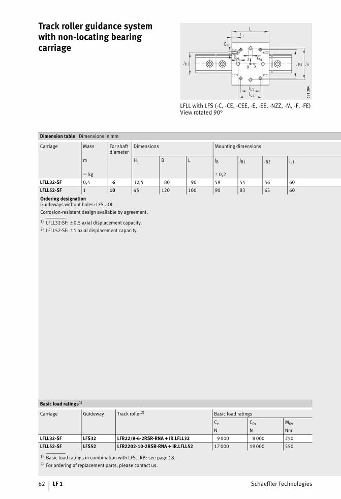
Track roller guidance systemwith non-locating bearing carriage
LFLL with LFS (-C, -CE, -CEE, -E, -EE, -NZZ, -M, -F, -FE)View rotated 90°
121
204
121
204
Ordering designationGuideways without holes: LFS..-OL.Corrosion-resistant design available by agreement.
1) LFLL32-SF: �0,5 axial displacement capacity.2) LFLL52-SF: �1 axial displacement capacity.
1) Basic load ratings in combination with LFS..-RB: see page 18.2) For ordering of replacement parts, please contact us.
Dimension table · Dimensions in mm
Carriage Mass For shaft diameter
Dimensions Mounting dimensions
m H1 B L JB JB1 JB2 JL1
� kg �0,2
LFLL32-SF 0,4 6 32,5 80 90 59 54 56 60
LFLL52-SF 1 10 45 120 100 90 83 65 60
Basic load ratings1)
Carriage Guideway Track roller2) Basic load ratings
Cz C0z M0y
N N Nm
LFLL32-SF LFS32 LFR22/8-6-2RSR-RNA + IR.LFLL32 9 000 8 000 250
LFLL52-SF LFS52 LFR2202-10-2RSR-RNA + IR.LFLL52 17 000 19 000 550
Schaeffler Technologies LF 1 63
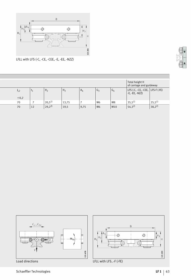
LFLL with LFS (-C, -CE, -CEE, -E, -EE, -NZZ)
121
201
121
201
Total height Hof carriage and guideway
JL2 t1 H2 H3 A4 G3 G4 LFS (-C, -CE, -CEE,-E, -EE, -NZZ)
LFS-F (-FE)
�0,2
70 7 20,51) 13,75 7 M6 M8 35,51) 25,51)
70 12 29,22) 19,5 9,75 M6 M10 54,32) 38,22)
Load directions LFLL with LFS..-F (-FE)
121
678
121
678
121
203
121
203

64 LF 1 Schaeffler Technologies
Track roller guidance systemwith bogie carriage
LFDL..-B with LFS (-C, -CE, -CEE, -E, -EE, -NZZ)
0001
A408
0001
A408
Corrosion-resistant design available by agreement.
1) In order to protect the raceways, the carriages can also be fittedwith the lubrication and wiper unit AB (special accessory).Please contact us.
2) For ordering of replacement parts, please contact us.3) Tightening torque for track roller bolts, concentric bolts are supplied tightened to MA.
1) Basic load ratings in combination with LFS..-RB: see page 18.2) For ordering of replacement parts, please contact us.
Dimension table · Dimensions in mm
Carriage1) Mass Track roller2) For shaft diameter
Dimensions Mounting dimensions
m H1 B L JB JB1
� kg
LFDL32-B1 LFR50/8-6-2Z 6
4380 100 60 54
LFDL32-SF 37
LFDL52-B2,5 LFR5201-10-2Z 10
65,1120 150 90 83
LFDL52-SF 55
Basic load ratings1)
Carriage Guideway Track roller2) Basic load ratings
Cy C0y Cz C0z M0x M0y M0z
N N N N Nm Nm Nm
LFDL32-B LFS32 LFR50/8-6-2Z4 100 2 400 6 600 4 200 30 130 70
LFDL32-SF LFS32 LFR50/8-6-2ZLFDL52-B LFS52 LFR5201-10-2Z
10 000 5 200 16 800 10 000 110 380 200LFDL52-B-SF LFS52 LFR5201-10-2Z

Schaeffler Technologies LF 1 65
LFDL-SF with LFS (-C, -CE, -CEE, -E, -EE, -NZZ)
203
042
203
042
Top view
121
246
121
246
Total height Hof carriage and guideway
JL1 JL2 H2 H3 T5 G4 N5 G6 MA3) LFS (-C, -CE, -CEE,
-E, -EE, -NZZ)Standard
+0,3 Nm
60 70 29,2 9 5 M8 21 M8 15 44,2
76 90 41 11 6 M10 26 M10 40 66,1
Load directions
121
650
121
650
Track rollersBoltsGuideways

Schaeffler Technologies LF 1 67
Page
Track rollers, bolts, guideways
Product overview Track rollers ........................................................................... 68
Features .............................................................................................. 69
Possible combinations of track rollers and guideways ............. 71
Design andsafety guidelines
Adjacent construction for non-locating bearing track rollers..... 72
Product overview Bolts ...................................................................................... 73
Features .............................................................................................. 74
Product overview Guideways ............................................................................. 76
Features .............................................................................................. 78
Design andsafety guidelines
Hole patterns of guideways..................................................... 80
Dimension tables Locating bearing track rollers.................................................. 84
Bolts ...................................................................................... 88
Non-locating bearing track rollers ........................................... 90
Possible combinations of track rollers and bolts ..................... 91
Guideways ............................................................................. 94
Closed oval tracks with guideway connectors VBS ................... 102

68 LF 1 Schaeffler Technologies
Product overview Track rollers
Locating bearingtrack roller
LFR LFRI
190
279A
190
279A
0001
A44E
0001
A44E
Non-locating bearingtrack roller
LFR..-2RSR-NA LFR..-2RSR-RNA
203
058
203
058
203
059
203
059
Schaeffler Technologies LF 1 69
Track rollers
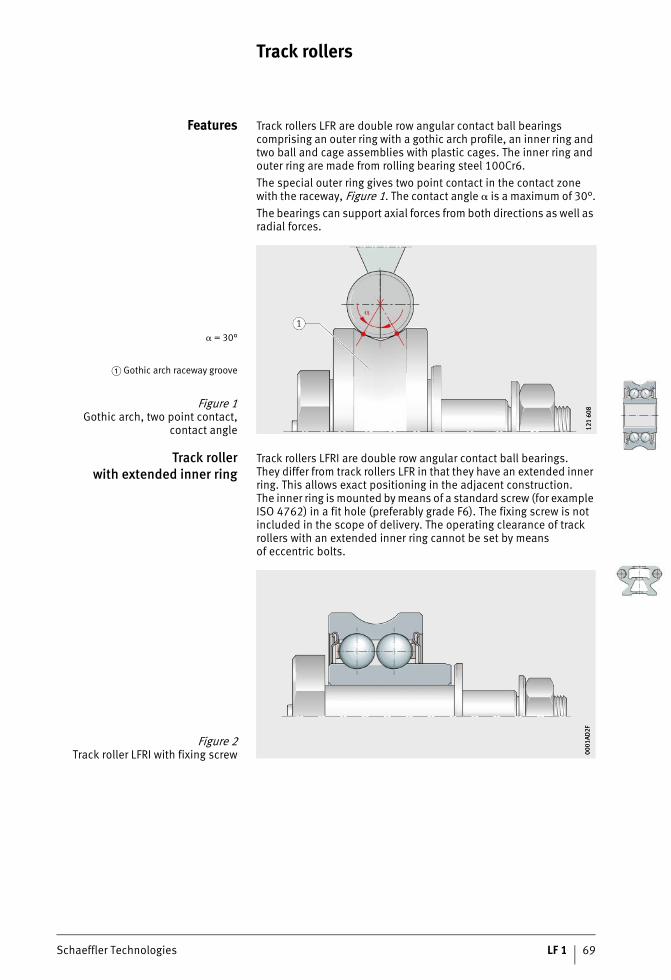
Features Track rollers LFR are double row angular contact ball bearings comprising an outer ring with a gothic arch profile, an inner ring and two ball and cage assemblies with plastic cages. The inner ring and outer ring are made from rolling bearing steel 100Cr6.The special outer ring gives two point contact in the contact zone with the raceway, Figure 1. The contact angle � is a maximum of 30°.The bearings can support axial forces from both directions as well as radial forces.
Track rollerwith extended inner ring
Track rollers LFRI are double row angular contact ball bearings.They differ from track rollers LFR in that they have an extended inner ring. This allows exact positioning in the adjacent construction.The inner ring is mounted by means of a standard screw (for example ISO 4762) in a fit hole (preferably grade F6). The fixing screw is not included in the scope of delivery. The operating clearance of track rollers with an extended inner ring cannot be set by meansof eccentric bolts.
� = 30°
� Gothic arch raceway groove
Figure 1Gothic arch, two point contact,
contact angle 121
608
121
608
Figure 2Track roller LFRI with fixing screw 00
01AD
2F00
01AD
2F

70 LF 1 Schaeffler Technologies
Track rollers
Sealing and lubrication Gap seals on both sides protect the rolling element system against contamination. Bearings with this seal type have the suffix 2Z.The track rollers are also available on request with contact sealson both sides, suffix 2RS and 2RSR.The track rollers are greased for life and are therefore maintenance-free. From outside diameter 52 mm, the inner ring hasa lubrication bore.
Seal types Seal types and their specific features: see table.
Specific features
Corrosion-resistant design The inner ring and outer ring are made from corrosion-resistant steel. The rolling elements are protected against corrosion by the grease.Corrosion-resistant designs have contact seals and the suffix 2RS-RB or 2RSR-RB.
Accuracyand internal clearance
The dimensional and geometrical accuracies correspond to tolerance class PN to DIN 620.The radial internal bearing clearance corresponds approximatelyto internal clearance group Group N in accordance with ISO 5753-1; internal clearance classes: see Catalogue HR 1, Rolling Bearings.
Further information Further information is given on the following pages:■ dimension tables, see page 90 and page 91■ bolts, see page 73■ guideways, see page 76■ accessories, see page 106.
2Z sealGap seal:■ not radially preloaded■ low friction■ to be used with low levels of contamination
2RSR sealContact seal:■ radially preloaded■ to be used with higher requirements for sealing action and
under heavy contamination
2RS sealContact seal:■ axially preloaded■ to be used with higher requirements for sealing action and
under heavy contamination

Schaeffler Technologies LF 1 71
Possible combinationsof track rollers and guideways
The tables show the possible combinations of track rollerswith the guideways LFS and shaft and support rail unit TS.
Combinations with guideways LFS
1) Width b and shaft diameter dLw: see dimension tables for guideways.
Combinations with guideways LFS(continued)
1) Width b and shaft diameter dLw: see dimension tables for guideways.
Combinations with shaft andsupport rail units TS1)
1) Shaft and support rail units TS and shaft diameter dLw:see Catalogue WF 1, Shaft Guidance Systems.
Width and shaft diameter1)
Track roller LFR
LFS dLw 50/5-4 50/5-6 50/8-6 5201-10 5301-10 5302-10
20 4 ● – – – – –
25 6 – ● ● – – –
32 6 – – ● – – –
42 10 – – – ● ● ●
52 10 – – – ● ● ●
86 10 – – – ● ● ●
120 10 – – – ● ● ●
● available size
Width and shaft diameter1)
Track roller LFRI
LFS dLw 50/8-6 5201
20 4 – –
25 6 ● –
32 6 ● –
42 10 – ●
52 10 – ●
86 10 – ●
120 10 – ●
● available size
Shaft diame-ter
Track roller LFR
dLw1) 5201-12 5204-16 5206-20 5206-25 5207-30 5208-40 5308-50
12 ● – – – – – –
16 – ● – – – – –
20 – – ● – – – –
25 – – – ● – – –
30 – – – – ● – –
40 – – – – – ● –
50 – – – – – – ●
● available size
72 LF 1 Schaeffler Technologies
Track rollers
Design andsafety guidelines
Adjacent constructionfor non-locating bearing
track rollers
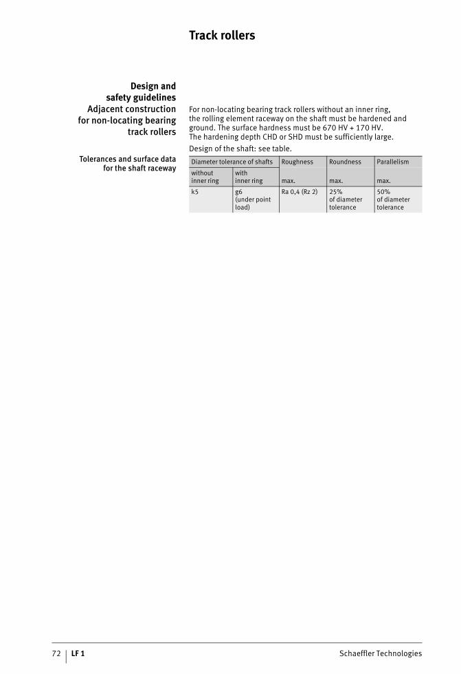
For non-locating bearing track rollers without an inner ring, the rolling element raceway on the shaft must be hardened and ground. The surface hardness must be 670 HV + 170 HV.The hardening depth CHD or SHD must be sufficiently large.Design of the shaft: see table.
Tolerances and surface datafor the shaft raceway
Diameter tolerance of shafts Roughness Roundness Parallelism
withoutinner ring
withinner ring max. max. max.
k5 g6(under point load)
Ra 0,4 (Rz 2) 25%of diameter tolerance
50%of diameter tolerance

Schaeffler Technologies LF 1 73
Product overview Bolts
Concentric LFZ LFZ..-A1
121
628
121
628
121
630
121
630
Eccentric LFE LFE..-A1
121
629
121
629
121
631
121
631
74 LF 1 Schaeffler Technologies
Bolts
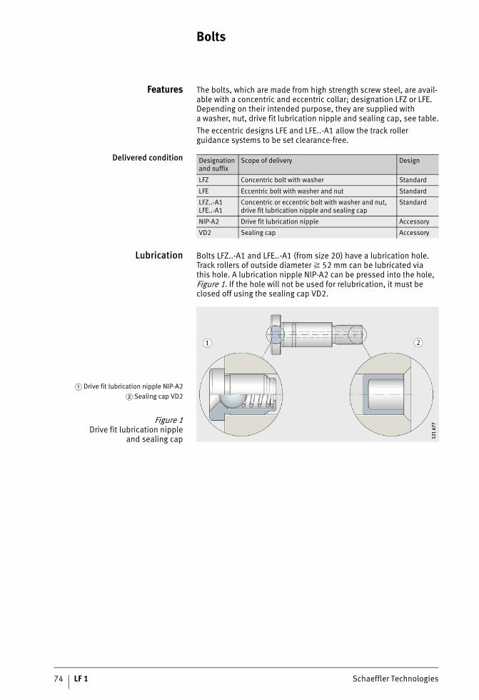
Features The bolts, which are made from high strength screw steel, are avail-able with a concentric and eccentric collar; designation LFZ or LFE. Depending on their intended purpose, they are supplied witha washer, nut, drive fit lubrication nipple and sealing cap, see table.The eccentric designs LFE and LFE..-A1 allow the track roller guidance systems to be set clearance-free.
Delivered condition
Lubrication Bolts LFZ..-A1 and LFE..-A1 (from size 20) have a lubrication hole. Track rollers of outside diameter 52 mm can be lubricated viathis hole. A lubrication nipple NIP-A2 can be pressed into the hole, Figure 1. If the hole will not be used for relubrication, it must be closed off using the sealing cap VD2.
Designation and suffix
Scope of delivery Design
LFZ Concentric bolt with washer Standard
LFE Eccentric bolt with washer and nut Standard
LFZ..-A1LFE..-A1
Concentric or eccentric bolt with washer and nut, drive fit lubrication nipple and sealing cap
Standard
NIP-A2 Drive fit lubrication nipple Accessory
VD2 Sealing cap Accessory
� Drive fit lubrication nipple NIP-A2� Sealing cap VD2
Figure 1Drive fit lubrication nipple
and sealing cap 121
677
121
677

Schaeffler Technologies LF 1 75
Corrosion-resistant design In this case, the bolts, washers and nuts are made fromcorrosion-resistant steel. These designs have the suffix RB.
Further information Further information is given on the following pages:■ dimension tables, see page 84■ track rollers, see page 68■ guideways, see page 76■ accessories, see page 106.

76 LF 1 Schaeffler Technologies
Product overview Guideways
Solid profileHollow section profile
LFS LFS..-C
121
581
121
581
121
590
121
590
Flat designTwo raceways or one raceway
LFS..-F LFS..-FH
121
593
121
593
121
594
121
594
Profiled section support rail LFS..-M
121
595
121
595
With slotsFor toothed racks or toothed belts
LFS..-N LFS..-NZZ
121
607
121
607
121
591
121
591

Schaeffler Technologies LF 1 77
Wide, flat designFor toothed racks or toothed belts
LFS120
121
596
121
596
Curved guideway element LFSR
121
582
121
582

78 LF 1 Schaeffler Technologies
Guideways
Features Guideway designs: see table.
Designs Guideway Design
LFS ■ With solid profilefor location from above through holes
LFS..-C ■ With hollow section profile (low mass)■ Location from above through holes■ The end faces of the hollow sections are
closed off using plastic end covers
LFS..-F ■ Flat guideway■ Preferably for applications with stationary
carriage and moving guideway■ Location from above through holes
LFS..-M ■ With support rail giving high bending rigidity■ The guideway can be incorporated
in modular constructions by means of slots. The slots are designed for nuts to DIN EN ISO 4032 and T-nuts to DIN 508
■ The hollow sections are closed off using plastic end covers. Special plastic endcovers are available for the slot closingstrips
LFSR ■ Curved guideway element made from steel■ Location from above through holes■ Combinations of curved guideway elements
or of curved guideway elements and straight guideways should be treated in the sameway as multi-piece guideways and must always be ordered together

Schaeffler Technologies LF 1 79
Designscontinued
Guidewayswithout fixing holes
All LFS guidances with the exception of LFSR are also available without fixing holes; suffix OL.
Guideway Design
LFS120 ■ Wide, low guideway■ With recesses for toothed racks or
toothed belts■ Location from above through holes
LFS..-FH ■ Flat guideway with only one shaft as raceway■ Mainly for applications with increased
support spacing■ Location from above through holes
LFS32-N, LFS..-NZZ ■ With T-slot for location from below■ The upper slot in the guideways and
the lateral slots are suitable for toothedracks or toothed belts
■ Supplied with special support washersfor the fixing screws; the quantity is basedon the length of the guideway
TSN ■ Composite guideway, aluminium supportrail with screw mounted raceway shaft
■ Location from above■ See Catalogue WF 1, Shaft Guidance Systems

80 LF 1 Schaeffler Technologies
Guideways
Design andsafety guidelines
Guideway hole patterns Unless specified otherwise, guideways have a symmetrical hole pattern, Figure 1.Upon request, an asymmetrical hole pattern may be available.In this case, aL aL min and aR aR min.
Hole pitch values The hole pitch values jL are stated in the dimension tables.For high loads, guideways are available with reduced hole pitch values jL, Figure 2.These guideways have the suffix E or EE; examples: LFS..-E, LFS..-EE.
� Symmetrical hole pattern� Asymmetrical hole pattern
Figure 1Hole patterns of guideways
with one row of holes 121
685
121
685
Figure 2Hole spacings jL 12
1 23
912
1 23
9

Schaeffler Technologies LF 1 81
Maximum number of pitchesbetween holes
The number of pitches between holes is the rounded down whole number equivalent to:
The spacings aL and aR are generally determined as follows:
For guideways with a symmetrical hole pattern:
Number of holes:
n –Maximum possible number of pitches between holesl mmGuideway lengthaL min, aR min mmMinimum values for aL, aR, see dimension tablesjL mmSpacing between holesaL, aR mmSpacing between start or end of guideway and nearest holex –Number of holes.
If the minimum values for aL and aR are not observed, the counter-bores of the holes may be intersected.

82 LF 1 Schaeffler Technologies
Guideways
Guideways without holes All guideways LFS are also available without holes, with the exception of LFSR. These guideways have the suffix OL, for example LFS..-OL.
Multi-piece guideways If the guideway length required is greater than lmax, the guideways are assembled from two or more sections matched to each other and marked accordingly. The sections may be of different lengths.The guideway joint is always arranged centrally between the fixing holes, Figure 3.
Accuracy of joint position In order to achieve accuracy of the joint position, additional fixing is recommended for guideways from size 32 if the spacing C7 is larger than the stated limit value, see table and Figure 4, page 83.In these cases, the guideways are supplied with the additional fixing hole already made.
Spacings for additional hole
� Marked joints
Figure 3Multi-piece guideways 12
1 24
012
1 24
0
Guideway Spacing between hole and end of guideway
C7Limit value
C8Limit value
mm mm
LFS32 (-C, -F) 30 11
LFS42-C 50 17
LFS52 (-C, -F) 50 17
LFS86-C 50 17
LFS120 50 17
Schaeffler Technologies LF 1 83
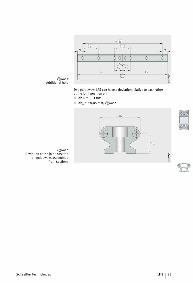
Two guideways LFS can have a deviation relative to each otherat the joint position of:■ b = �0,01 mm■ h4 = �0,05 mm, Figure 5.
Figure 4Additional hole 00
0978
5F00
0978
5F
Figure 5Deviation at the joint position
on guideways assembledfrom sections 00
0977
6F00
0977
6F

84 LF 1 Schaeffler Technologies
Locating bearing track rollers
LFR..-2Z
0001
A430
0001
A430
Corrosion-resistant design with suffix ..-RB.
1) Rolling contact diameter.2) Effective dynamic load rating as track roller (radial).3) Effective static load rating as track roller (radial).4) Fatigue limit load.5) Permissible dynamic limit load.6) Permissible static limit load.7) Corrosion-resistant design available by agreement.8) Lubricated for life, see page 19.9) Relubrication facility via inner ring, see page 19.
Dimension table · Dimensions in mm
Designation Mass Dimensions
m d Dmax B AT C
� kg
LFR50/5-4-2Z-HLC8)0,01 5 16 8 9 7
LFR50/5-4-2RS-RB-HLC8)
LFR50/5-6-2Z-HLC8)0,01 5 17 8 10,5 7
LFR50/5-6-2RS-RB-HLC8)
LFR50/8-6-2Z8)0,02 8 24 11 14 11
LFR50/8-6-2RS-RB8)
LFR5201-10-2Z8)0,08 12 35 15,9 20,63 15,9
LFR5201-10-2RS-RB8)
LFR5301-10-2Z8)0,1 12 42 19 24 19
LFR5301-10-2RS-RB8)
LFR5302-10-2Z8)0,17 15 47 19 26,63 19
LFR5302-10-2RS-RB8)
LFR5201-12-2Z8)0,08 12 35 15,9 21,75 15,9
LFR5201-12-2RS-RB8)
LFR5204-16-2Z9)0,23 20 52 22,6 31,5 20,6
LFR5204-16-2RS-RB9)
LFR5206-20-2Z9)0,43 25 72 25,8 41 23,8
LFR5206-20-2RS-RB7)9)
LFR5206-25-2Z9)0,43 25 72 25,8 43,5 23,8
LFR5206-25-2RS-RB9)
LFR5207-30-2Z9)0,66 30 80 29 51 27
LFR5207-30-2RS-RB7)9)
LFR5208-40-2Z9)1,36 40 98 38 62,5 36
LFR5208-40-2RS-RB7)9)
LFR5308-50-2Z9)1,4 40 110 46 72,5 44
LFR5308-50-2Z-RB7)9)

Schaeffler Technologies LF 1 85
LFR..-2Z
109
337
109
337
Load carrying capacity
ds Da1) rmin Cr w
2) C0r w3) Cur
4) Fr per5) F0r per
6)
N N N N N
4 14,54 0,2 1 560 850 43 1 700 1 700
6 15,8 0,2 1 630 900 44,5 2 270 1 800
6 22,8 0,3 4 100 2 300 115 2 550 4 600
10 32,25 0,6 8 400 5 000 250 4 750 10 000
10 38,95 0,613 200 7 700 370 6 400 15 400
13 900 8 200 390 19 600 16 400
10 44,25 1 14 500 9 100 455 9 400 18 200
12 33,1 0,6 8 300 5 000 250 4 650 10 000
16 49,14 1 15 300 10 100 520 10 500 20 200
20 64,68 1 23 100 16 400 870 21 100 33 000
25 65,35 1 22 700 16 100 850 18 800 32 000
30 76,02 1 23 100 16 400 1 100 18 500 41 500
40 90,36 1,1 38 500 29 000 1 480 51 000 58 000
50 101,7 1,1 54 000 40 500 2 000 69 000 81 000

86 LF 1 Schaeffler Technologies
Track rollersWith extended inner ringLocating bearing track roller
LFRI
0001
A42E
0001
A42E
Corrosion-resistant design available by agreement.
1) Rolling contact diameter.2) Effective dynamic load rating as track roller (radial).3) Effective static load rating as track roller (radial).4) Fatigue limit load.5) Permissible dynamic limit load.6) Permissible static limit load.
Dimension table · Dimensions in mm
Designation Mass Dimensions
m d Dmax B AT C C1
� kg
LFRI50/8-6-2Z 0,025 6,1 24 15,1 14 11 9,6
LFRI5201-10-2Z 0,09 10,5 35 20,7 20,63 15,9 12,75

Schaeffler Technologies LF 1 87
LFRI
Da
0000
1A42
F
Load carrying capacity
D1 ds Da1) rmin Cr w
2) C0r w3) Cur
4) Fr per5) F0r per
6)
j6 N N N N N
12,6 6 22,8 0,5 4 100 2 300 115 2 550 4 600
17,8 10 32,25 0,5 8 300 5 000 250 4 550 8 300

88 LF 1 Schaeffler Technologies
Bolts
LFZ, LFE
109
145
109
145
Corrosion-resistant design available by agreement.
1) No washer required.2) Without lubrication hole.
Dimension table · Dimensions in mm
Designation Mass Dimensions
d G1 G2 L L2 L3 L1 A5
m
� kg
LFZ050,01 5 M4
– 19,5 16 9,5 – –
LFE05-0,5 M4 – – 9 20 15
LFZ080,02 8 M8
– 28,3 24,3 15 – –
LFE08-1 M8�0,75 – – 13 32,5 21,6
LFZ120,04
12
M10– 43 36 22 – –
LFE12-1 M10 – – 19,5 50 33,5
LFZ12/M120,06 M12
– 50,8 43,824
– –
LFE12-1/M12 M12 – – 57 41
LFZ150,06 15 M12
– 50,8 43,8 23,8 – –
LFE15-1 M12 – – 24 57 41
LFZ12�45-A12)0,04 12 M10�1,5 – 50 45 16 –
–
LFE12�45-A12) 30
LFZ20�67-A10,2 20 M16�1,5 – 75 67 23 –
–
LFE20�67-A1 45
LFZ25�82-A10,4 25 M20�1,5 – 92 82 30 –
–
LFE25�82-A1 57
LFZ30�95-A10,62 30 M24�1,5 – 107 95 32 –
–
LFE30�95-A1 67
LFZ40�107-A11,1
40 M30�1,5 –
117 107
42 –
–
LFE40�107-A1 72
LFZ40�115-A11,2 125 115
–
LFE40�115-A1 72

Schaeffler Technologies LF 1 89
LFZ..-A1, LFE..-A1
0001
AC2C
0001
AC2C
LFZ05 and LFE05-0,5
0001
A431
0001
A431
L7 Ds E H1 S DK ds d1 Width across flats
W W1 W2
– 10– –
–1) 10– –
3 – –
0,5 2,9 – – 7 2
–14
– –1 – – –
13 – –
3 1 4 – 13 5
–21
– –
1,8 – – –
17 – –
5 1 8,4 – 17 6
–19
– – 17 – –
5 1 6,5 – 17 6
–21
– –2 – – –
19 – –
4 1 6,5 – 19 6
– 21–
8 2 20 ––
17 17 –0,75 10
– 30–
13 3 30 5,9–
27 24 –1 17
– 37–
16 3 40 5,9–
36 30 –1 22
– 44–
19 4 45 5,9–
41 36 –1 27
– 56
–
24 4 55 5,9
–
46 46 –1 36
– –
1 36
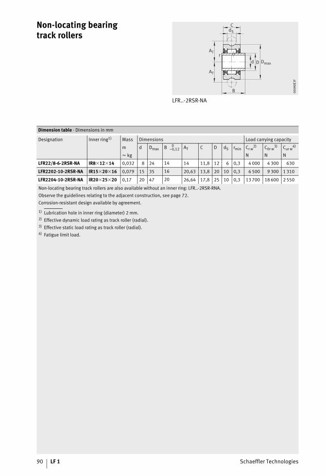
90 LF 1 Schaeffler Technologies
Non-locating bearingtrack rollers
LFR..-2RSR-NA
d
B
Dr
C
AT
AT
dS
Dmax
000A
0E3F
Non-locating bearing track rollers are also available without an inner ring: LFR..-2RSR-RNA.Observe the guidelines relating to the adjacent construction, see page 72.Corrosion-resistant design available by agreement.
1) Lubrication hole in inner ring (diameter) 2 mm.2) Effective dynamic load rating as track roller (radial).3) Effective static load rating as track roller (radial).4) Fatigue limit load.
Dimension table · Dimensions in mm
Designation Inner ring1) Mass Dimensions Load carrying capacity
m d Dmax B 0–0,12 AT C D dS rmin Cr w
2) C0r w3) Cur w
4)
� kg N N N
LFR22/8-6-2RSR-NA IR8�12�14 0,032 8 24 14 14 11,8 12 6 0,3 4 000 4 300 630
LFR2202-10-2RSR-NA IR15�20�16 0,079 15 35 16 20,63 13,8 20 10 0,3 6 500 9 300 1 310
LFR2204-10-2RSR-NA IR20�25�20 0,17 20 47 20 26,64 17,8 25 10 0,3 13 700 18 600 2 550

Schaeffler Technologies LF 1 91
Possible combinationsof track rollers and bolts
Mounting situation
0009
9782
0009
9782
1) With eccentric bolts, the dimension a varies by �E in accordance with the table, page 89.2) No washer required.
Dimension table · Dimensions in mm
Designation Dimensions
Locating bearing track roller Bolt a1) b S c d
LFR50/5-4-2Z2) LFZ059 8 – 4 11,5
LFE05-0,5
LFR50/5-6-2ZLFZ05
10,5 8 1 5 11,5LFE05-0,5
LFR50/8-6-2ZLFZ08
14 12 1 6,516
LFE08-1 20,5
LFR5201-10-2ZLFZ12
20,65 17,7 1,8 9,724,7
LFE12-1 32,3
LFR5301-10-2ZLFZ12/M12
24 20,8 1,8 11,327,8
LFE12-1/M12 34,8
LFR5302-10-2ZLFZ15
26,65 21 2 11,528
LFE15-1 35
LFR5201-12-2ZLFZ12�45-A1
21,75 17,9 2 9,9 22,9LFE12�45-A1
LFR5204-16-2ZLFZ20�67-A1
31,5 25,6 3 14,3 33,6LFE20�67-A1
LFR5206-20-2ZLFZ25�82-A1
41 28,8 3 15,9 38,8LFE25�82-A1
LFR5206-25-2ZLFZ25�82-A1
43,5 28,8 3 15,9 38,8LFE25�82-A1
LFR5207-30-2ZLFZ30�95-A1
51 33 4 18,5 45LFE30�95-A1
LFR5208-40-2ZLFZ40�107-A1
62,5 42 4 23 52LFE40�107-A1
LFR5308-50-2ZLFZ40�115-A1
72,5 50 4 27 60LFE40�115-A1

92 LF 1 Schaeffler Technologies
Possible combinationsof track rollers and boltsFlying bearing arrangement with bolt ..-A1
Bolt ..-A1
0001
AD30
0001
AD30
1) For nuts in accordance with DIN 934, included in the scope of delivery.2) For washers in accordance with DIN 125, included in the scope of delivery.3) Recommended minimum wall thickness.
Dimension table · Dimensions in mm
Designation Dimensions
Locating bearing track roller
Bolt a c d d1 G11) S2) W3) S1 b1 dLW B
WasherDIN 125-A
LFR5201-12-2ZLFZ12�45-A1
21,75 9,7512 –
M10�1,5 2 122,5 13
12 15,9LFE12�45-A1 – 10 2 10,5
LFR5204-16-2ZLFZ20�67-A1
31,5 11,320 –
M16�1,5 3 203 21
20 22,6LFE20�67-A1 – 17 3 17
LFR5206-20-2ZLFZ25�82-A1
41 12,925 –
M20�1,5 3 254 27
20 25,8LFE25�82-A1 – 22 3 23
LFR5206-25-2ZLFZ25�82-A1
43,5 12,925 –
M20�1,5 3 254 27
25 25,8LFE25�82-A1 – 22 3 23
LFR5207-30-2ZLFZ30�95-A1
51 14,530 –
M24�1,5 4 324 31
30 29LFE30�95-A1 – 27 4 28
LFR5208-40-2ZLFZ40�107-A1
62,5 1940 –
M30�1,5 4 406 41
40 38LFE40�107-A1 – 36 5 37
LFR5308-50-2ZLFZ40�115-A1
72,5 2340 –
M30�1,5 4 406 41
40 46LFE40�115-A1 – 36 5 37

Schaeffler Technologies LF 1 93

94 LF 1 Schaeffler Technologies
Guideways
LFS LFS..-C
121
169
121
169
121
207
121
207
Guideways of corrosion-resistant design: LFS..-RB, observe note on page 18.Modulus of elasticity for LFS..-C (-CE, -CEE, -E, -EE, -F, -FE): 72 000 N/mm2.Guideways LFS, LFS..-C and LFS..-F available without holes: LFS..-OL (-C-OL, -F-OL).� Underside marked
1) Maximum length of single-piece guideways; longer guideways are suppliedin several sections and are marked accordingly.Observe the length tolerances, see page 30.
2) aL and aR are dependent on the guideway length lmax, calculation: see page 80.3) Under maximum load Fz and F0z, support washers to DIN 433 and the maximum tightening torque
according to the table, page 29, are required.4) The design of the hollow sections is dependent on the size.5) Counterbore depth for screws to DIN 7984.6) If support washers to DIN 433 are used, screws to DIN 7984 are recommended.
Dimension table · Dimensions in mm
Designation Mass Dimensions Mounting dimensions
m b h lmax1) b1 a2 jL aL
2) aR2)
� kg min. max. min. max.
LFS20 0,6 20 12,2 2 400 17 16 62,5 9 54 9 54
LFS25 1,1 25 15 2 400 21 19 62,5 10 54 10 54
LFS321,6
3220 6 000 24
26
125
11
116
11
116
LFS32-E 62,5 52 52
LFS32-C4)1,1
125 116 116
LFS32-CE4) 62,5 52 52
LFS32-F 1 10 4 000 – 125 116 116
LFS42-C4)
2,2 4220 6 000 28
32
12520
11320
113
LFS42-CE4) 62,551 51
LFS42-F 15 4 000 125 17 17
LFS524,4
52
34
6 000
40
42
250
17
235
17
235
LFS52-E 125 110 110
LFS52-EE 62,5 49 49
LFS52-C4)
3
250 235 235
LFS52-CE4) 125 110 110
LFS52-CEE4) 62,5 49 49
LFS52-F18 –
250 235 235
LFS52-FE 125 110 110
LFS86-C4)4,4 86 34 6 000 71 76
25017
23517
235
LFS86-CE4) 125 110 110
LFS1207,9 120 25 8 000 100 110
25017
235 17 235
LFS120-E 125 110 17 110

Schaeffler Technologies LF 1 95
LFS, LFS..-C (-F)View rotated 90°
LFS..-F Bending axes12
1 17
612
1 17
6
121
170
121
170
121
273
121
273
Surface data
dLW h4 h1 N1 N33) Cross-
sectionalarea
y-y z-z
ly Wy ez lz Wz
mm2 mm4 mm3 mm mm4 mm3
4 9 7,6 4,5 8 165 3 065 362 6,4 2 053 324
6 10,6 8,5 5,5 10 237 6 390 608 7,5 4 510 600
615 12
6,5 12
440 20 100 1 440 10,4 14 100 1 360
261 18 305 1 165 10,1 10 072 995
5 3,55) 230 11 300 810 5 2 190 438
1012,6 126)
9 15358 33 929 1 858 10,1 14 052 1 391
7,5 85) 370 29 280 1 864 7,5 16 200 2 160
10
25,1 21
11 19
1 170 138 624 5 878 17,8 113 037 6 350
649 113 821 4 896 17,1 74 878 4 378
9 85) 670 84 000 3 610 9 19 900 2 211
10 25,1 216) 13 21 1 185 613 720 16 587 17,5 155 160 8 866
10 16,1 12 11 19 2 468 2 330 980 40 751 12,5 9 365 117 074
LFS120 LFS120
0001
A43E
0001
A43E
121
676
121
676

96 LF 1 Schaeffler Technologies
Guideways
LFS..-FH
121
174
121
174
Guideways of corrosion-resistant design: LFS..-RB, observe note on page 18.Guideways LFS..-FH available without holes: LFS..-FH-OL.Modulus of elasticity for LFS..-FH (-FHE, -FHEE): 72 000 N/mm2.� Underside marked
1) Maximum length of single-piece guideways; longer guideways are suppliedin several sections and are marked accordingly.Observe the length tolerances, see page 30.
2) aL and aR are dependent on the guideway length lmax, calculation: see page 80.3) For screw to DIN 912-8.8 (DIN EN ISO 4762),
under maximum load support washers to DIN 433 (DIN EN ISO 7092) are required.4) Counterbore depth for screws to DIN 7984.
Dimension table · Dimensions in mm
Designation Mass Dimensions Mounting dimensions
m b h lmax1) a2 a6 jL aL
2) aR2)
� kg min. max. min. max.
LFS32-FH0,8 26 10 4 000 23 13
12511
1166
116
LFS32-FHE 62,5 52 52
LFS52-FH2,3 42 18 6 000 37 21
250
17
235
10
235
LFS52-FHE 125 110 110
LFS52-FHEE 62,5 49 49
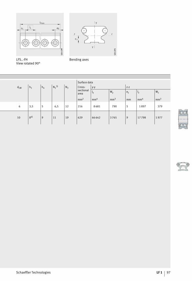
Schaeffler Technologies LF 1 97
LFS..-FHView rotated 90°
Bending axes12
1 17
912
1 17
9
121
273
121
273
Surface data
dLW h1 h4 N13) N3 Cross-
sectional area
y-y z-z
ly Wy ez lz Wz
mm2 mm4 mm3 mm mm4 mm3
6 3,5 5 6,5 12 216 8 681 790 5 1 897 379
10 84) 9 11 19 629 66 642 3 765 9 17 798 1 977

98 LF 1 Schaeffler Technologies
Guideways
LFS32-N LFS52-NZZ
121
172
121
172
121
171
121
171
Guideways of corrosion-resistant design: LFS..-RB, observe note on page 18.Modulus of elasticity for LFS..-M (-N, -NZZ, -ZZ): 72 000 N/mm2.� For LFS52-M and LFS32-M; � For LFS25-M; � Detail of slot
1) Maximum length of single-piece guideways; longer guideways are suppliedin several sections and are marked accordingly.Observe the length tolerances, see page 30.
2) For screw to DIN 931 (DIN EN ISO 4014), DIN 933-8.8 (DIN EN ISO 4017),special support washers included in scope of delivery for guideways LFS52-NZZ.
3) Recommended screw pitch (hole spacing), see page 80.4) One core hole for non-cutting thread drill or self-tapping screws to DIN 7513.5) The guideway LFS..-M can only be combined with carriages with adjustable clearance.
If SF and LFCL carriages are to be used, please contact us in advance.
Dimension table · Dimensions in mm
Desig-nation
Mass Dimensions Mounting dimensions
m b h lmax1) b1 a2 b3
2) b4 b5 t6 a7 jL3) dLW h1 h2 h5 h4
� kg/m
LFS25-M5) 3,5 25 46 4 000 56 19 – – 5,2 30 – – 6 – 22 – 41,6
LFS32-M5) 6,432
66,5 8 000 7526
– – 10,2 43–
–6
– 25–
61
LFS32-N 1,4 20 4 000 24 6,5 10,5 10,5 – 125 4 6 15
LFS52-M5) 11,252
98,68 000
11242
18 44 10,2 80 52 –10
– 25 50 89,7
LFS52-NZZ 3,9 34 46,5 11 18,5 18,5 4,7 – 250 6,4 9 – 25,1
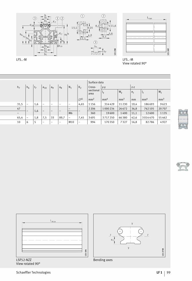
Schaeffler Technologies LF 1 99
LFS..-M
121
238
121
238
LFS..-MView rotated 90°
121
249
121
249
Surface data
h7 h6 t7 a10 a9 a8 N1 K2 Cross-sectional area
y-y z-z
ly Wy ez lz Wz
�4) mm2 mm4 mm3 mm mm4 mm3
31,5 – 1,6 – – – – 4,65 1 156 314 429 11 230 19,4 186 693 9 623
47– 1,6 – – –
––
2 206 1 000 234 26 672 36,8 762 105 20 707
– M6 360 19 600 1 400 11,1 12 600 1 135
65,4 – 1,8 7,5 33 89,7 – 7,45 3 691 3 717 250 66 380 42,6 3 014 470 55 462
10 6 5 – – – M10 – 994 170 350 7 327 16,8 82 786 4 927
LSF52-NZZView rotated 90°
Bending axes
121
194
121
194
121
273A
121
273A

100 LF 1 Schaeffler Technologies
Guideways
LFSR..-ST LFSR../90-ST
121
494
121
494
121
231
121
231
Attention!If curved guideway elements are required in combination with straight guideway sections,these must always be ordered together as a unit.Note the guidelines relating to mounting of curved guideway elements, see page 27.Corrosion-resistant design available by agreement.
1) For screw to DIN ISO 4762-8.8.2) Number of holes on the pitch circle r1.
Dimension table · Dimensions in mm
Designation Mass Dimensions
m b h r � b1 a2
� kg °
LFSR32-100/90-ST 0,5
32 20
100
90
24 26
LFSR32-100/180-ST 1 180
LFSR32-100/360-ST 2 360
LFSR32-150/90-ST 0,8
150
90
LFSR32-150/180-ST 1,6 180
LFSR32-150/360-ST 3,2 360
LFSR32-300/90-ST 1,7
300
90
LFSR32-300/180-ST 3,4 180
LFSR32-300/360-ST 6,8 360
LFSR32-500/90-ST 2,9
500
90
LFSR32-500/180-ST 5,8 180
LFSR32-500/360-ST 11,6 360
LFSR52-150/90-ST 2
52 34
150
90
40 42
LFSR52-150/180-ST 4 180
LFSR52-150/360-ST 8 360
LFSR52-300/90-ST 4,5
300
90
LFSR52-300/180-ST 9 180
LFSR52-300/360-ST 18 360
LFSR52-500/90-ST 7,8
500
90
LFSR52-500/180-ST 15,6 180
LFSR52-500/360-ST 31,2 360

Schaeffler Technologies LF 1 101
LFSR..-ST
121
496
121
496
dLW h1 h4 N11) N3 x2) r1 � �/2
° °
6 13,5 15 6,5 12
3
84 30 156
12
3
134 30 156
12
4
284 22,5 11,258
16
5
484 18 910
20
10 21 25,1 11 19
3
124 30 156
12
4
274 22,5 11,258
16
5
474 18 910
20

102 LF 1 Schaeffler Technologies
Closed oval trackswith guideway connectors VBS
LFS (section A–A)
121
169
121
169
Attention!If curved guideway elements are required in combination with straight guideway sections,these must always be ordered together as a unit.Closed oval tracks can only be ordered as a single unit.A unit consists of two curved guideway elements LFSR with an arc dimension 180°and two straight guideways LFS or a unit of four curved guideways LFSR with an arcdimension 90° and four straight guideways LFS.Note the guidelines relating to mounting of curved guideway elements, see page 27.
1) Maximum length of single-piece guideways.2) For screw to DIN ISO 4762-8.8.3) Number of holes on the pitch circle r1.
Dimension table · Dimensions in mm
Closed oval tracks Dimensions Mounting dimensions
Designation b h � lmax1) b1 a2
with two 180° arcs with four 90° arcs °
– LFS32�..�..-OV-100-VBS
32 20
90
6 000 24 26
LFS32�..-OV-100-VBS – 180
– LFS32�..�..-OV-150-VBS 90
LFS32�..-OV-150-VBS – 180
– LFS32�..�..-OV-300-VBS 90
LFS32�..-OV-300-VBS – 180
– LFS32�..�..-OV-500-VBS 90
LFS32�..-OV-500-VBS – 180
– LFS52�..�..-OV-150-VBS
52 34
90
6 000 40 42
LFS52�..-OV-150-VBS – 180
– LFS52�..�..-OV-300-VBS 90
LFS52�..-OV-300-VBS – 180
– LFS52�..�..-OV-500-VBS 90
LFS52�..-OV-500-VBS – 180
Closed oval track with two 180° arcs
203
043
203
043

Schaeffler Technologies LF 1 103
LFSR (section B–B)12
1 49
412
1 49
4
jL aL, aR dLW h1 h4 N12) N3 x3) r r1 �
min. max. °
125
36
116 6 12 15 6,5 12
3100 84
306
30
3150 134
6
4300 284 22,5
8
5500 484 18
10
250
49
235 10 21 25 11 19
3150 124 30
6
41
4300 274 22,5
8
5500 474 18
10
Closed oval track with four 90° arcs
203
044
203
044
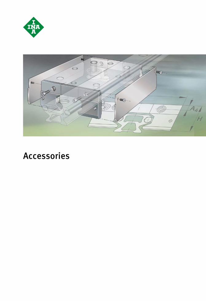
Accessories
Schaeffler Technologies LF 1 105
Page
Accessories
Product overview Accessories............................................................................ 106
Features Guideway connector for guideways ......................................... 108
End plate................................................................................ 108
Lubrication and wiper units .................................................... 109
Cap wipers ............................................................................. 110
Side plate............................................................................... 111
Stops ..................................................................................... 111
End cover ............................................................................... 111
Slot closing strip .................................................................... 111
Fasteners ............................................................................... 112
Dimension tables Guideway connector for guideways LFS ................................... 114
End plate................................................................................ 115
Lubrication and wiper units .................................................... 116
Cap wipers ............................................................................. 118
Side plate............................................................................... 119
Stops ..................................................................................... 120
End cover ............................................................................... 122
Slot closing strip .................................................................... 123

106 LF 1 Schaeffler Technologies
Product overview Accessories
Guideway connectorfor guideways
VBS
203
034A
203
034A
End plate ANS.LFS
121
432
121
432
Lubrication andwiper units
AB.W AB
172
003
172
003
121
308
121
308
Cap wipers AB.LFR
121
297
121
297

Schaeffler Technologies LF 1 107
Side plate ABAL
121
298
121
298
Stops PAH PASTP
121
295
121
295
121
426
121
426
End coverSlot closing strip
KA.LFS NAD
121
635
121
635
121
636
121
636
FastenersFixing screw
T-nutsT-bolt
T-stripFixing bracket
Fixing lug
MU, SHR, LEIS-M WKL, SPPR
121
633
121
633
121
634
121
634

108 LF 1 Schaeffler Technologies
Accessories
FeaturesGuideway connector
for guidewaysGuideway connectors VBS are accessories for curved and straight LFS guideways.They comprise:■ pins■ bushes■ grub screws.The guideway connectors are suitable for all LF guideways. Joined curved guideways are supplied as standard with the guideway connector. Joined straight guideways are available as an optionwith the guideway connector.The VBS reduces running noise at the joint, ensures an increased operating life for the guidance system and improves the operational reliability.
End plate End plates ANS.LFS (also for use with hollow section guideways)are made from steel. They secure the rolled-in raceway shafts by means of form fit. In the case of solid section guideways, holes must be made in the end faces (by the customer) for screw mountingof the end plates.The end plates prevent the shaft creep that can occur under unfavourable conditions on all guideways that comprise an alu-minium support rail into which a steel shaft is rolled or pressed.These can be supplied already fitted, but this must be indicated when ordering.

Schaeffler Technologies LF 1 109
Lubrication and wiper unitsDesign AB.W The lubrication and wiper unit AB.W comprises a plastic housing and
is fixed to the adjacent construction. It contains a felt lubrication insert. This is supplied soaked with oil that has H1 approval and can be replenished with oil via a hole in the housing if necessary.Lubrication and wiper units AB.W are supplied with fixing screws.
Design AB The lubrication and wiper unit AB comprises a plastic housing and is screw mounted to the end of the carriage LFL-SF or LFDL. It contains felt lubrication inserts on both sides. These are supplied soaked with oil that has H1 approval and can be replenished with oil via lubrication nipples if necessary. The lubrication and wiper units AB can be fixed to carriages using two screws.If the lubrication and wiper unit AB is used together with a stop PAH or PASTP, the central section must be removed, see Figure 1.
� Central section, supplied loose� Felt lubrication inserts
� Fixing screws, supplied loose
Figure 1Lubrication and wiper unit AB 00
07F2
E100
07F2
E1
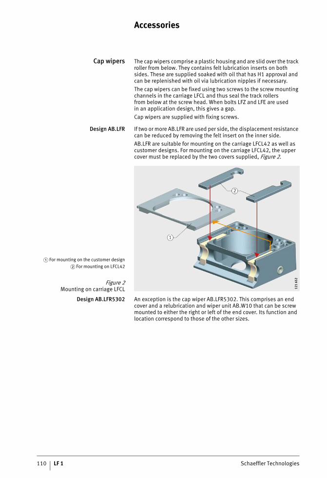
110 LF 1 Schaeffler Technologies
Accessories
Cap wipers The cap wipers comprise a plastic housing and are slid over the track roller from below. They contains felt lubrication inserts on both sides. These are supplied soaked with oil that has H1 approval and can be replenished with oil via lubrication nipples if necessary.The cap wipers can be fixed using two screws to the screw mounting channels in the carriage LFCL and thus seal the track rollersfrom below at the screw head. When bolts LFZ and LFE are usedin an application design, this gives a gap.Cap wipers are supplied with fixing screws.
Design AB.LFR If two or more AB.LFR are used per side, the displacement resistance can be reduced by removing the felt insert on the inner side.AB.LFR are suitable for mounting on the carriage LFCL42 as well as customer designs. For mounting on the carriage LFCL42, the upper cover must be replaced by the two covers supplied, Figure 2.
Design AB.LFR5302 An exception is the cap wiper AB.LFR5302. This comprises an end cover and a relubrication and wiper unit AB.W10 that can be screw mounted to either the right or left of the end cover. Its function and location correspond to those of the other sizes.
� For mounting on the customer design� For mounting on LFCL42
Figure 2Mounting on carriage LFCL 12
1 65
212
1 65
2

Schaeffler Technologies LF 1 111
Side plate The side plate ABAL is made from plastic and can be screw mounted to the sides of carriages LFL..-SF. The side plates are used to sup-plement the lubrication and wiper units AB. The carriage can be sealed on all sides, with the exception of the underside, by means of two side plates and two lubrication and wiper units.The side plate is supplied with fixing screws.It can only be mounted in conjunction with the lubrication and wiper unit AB.
StopsDesign PAH The stop PAH comprises anodised aluminium and a buffer made
from shock-absorbent plastic. The stop can be placed at any position on guideways. It is then clamped in place by means of a screw.The stop is used as an end stop or restricts the travel of the carriage.The central section of lubrication and wiper units must be removedif the carriage is to run up against a stop PAH, see page 109.
Design PASTP The stop PASTP is made from plastic. It can be screw mountedin a threaded hole (to be made by the customer) in guideways.This hole can be drilled at any position on guideways LFS. The stop is used as an end stop or restricts the travel of the carriage.The central section of lubrication and wiper units must be removedif the carriage is to run up against a stop PASTP, see page 109.
End cover End covers KA are made from plastic. The end covers close off the end faces of the hollow sections in guideways LFS..-C and LFS..-Mas well as in the hollow section carriage LFCL.
Slot closing strip Slot closing strips NAD are made from plastic. They close off the slots in the guideway LFS..-M. For information on NAD, see publication AL 1, Driven Linear Units.

112 LF 1 Schaeffler Technologies
Accessories
FastenersFixing brackets, fixing lugs For location of LFS-M with the integral profiled aluminium support
rail, fixing brackets and fixing lugs are available, Figure 3, Figure 4, Figure 5 and table, page 113.
� WKL
Figure 3Fixing brackets 12
1 60
212
1 60
2
� SPPR
Figure 4Fixing lug 17
2 40
717
2 40
7
Figure 5Fixing brackets and fixing lugs 12
1 59
912
1 59
9
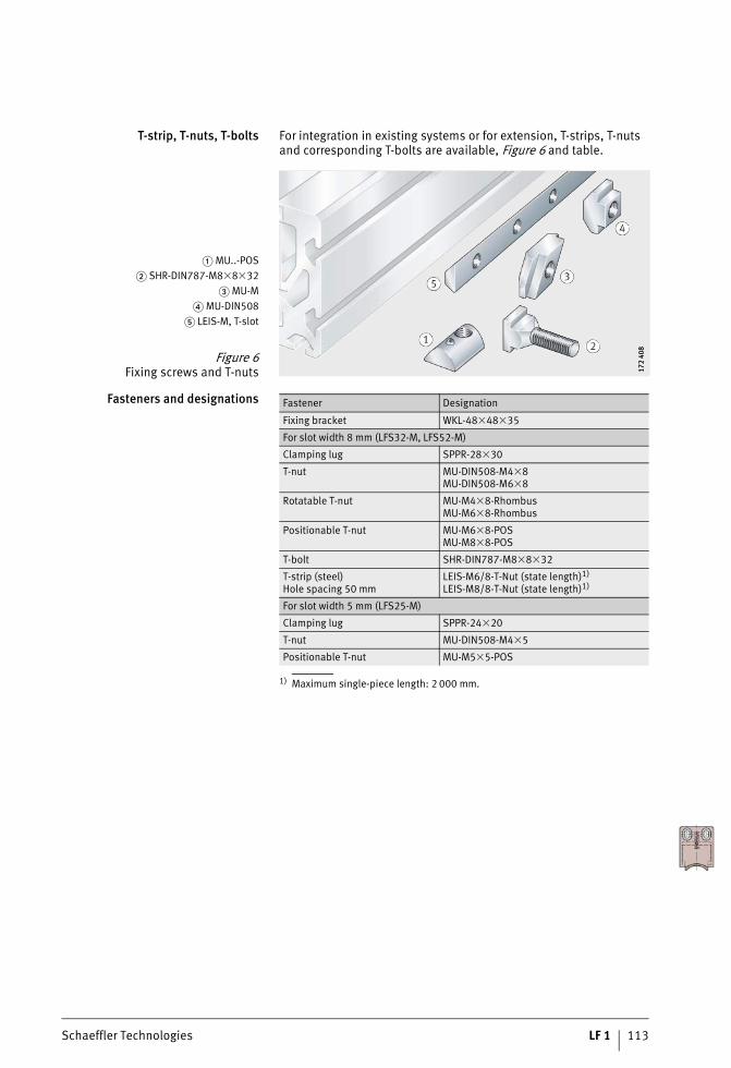
Schaeffler Technologies LF 1 113
T-strip, T-nuts, T-bolts For integration in existing systems or for extension, T-strips, T-nuts and corresponding T-bolts are available, Figure 6 and table.
Fasteners and designations
1) Maximum single-piece length: 2 000 mm.
� MU..-POS� SHR-DIN787-M8�8�32
� MU-M� MU-DIN508
� LEIS-M, T-slot
Figure 6Fixing screws and T-nuts 17
2 40
817
2 40
8
Fastener Designation
Fixing bracket WKL-48�48�35
For slot width 8 mm (LFS32-M, LFS52-M)
Clamping lug SPPR-28�30
T-nut MU-DIN508-M4�8MU-DIN508-M6�8
Rotatable T-nut MU-M4�8-RhombusMU-M6�8-Rhombus
Positionable T-nut MU-M6�8-POSMU-M8�8-POS
T-bolt SHR-DIN787-M8�8�32
T-strip (steel)Hole spacing 50 mm
LEIS-M6/8-T-Nut (state length)1)
LEIS-M8/8-T-Nut (state length)1)
For slot width 5 mm (LFS25-M)
Clamping lug SPPR-24�20
T-nut MU-DIN508-M4�5
Positionable T-nut MU-M5�5-POS
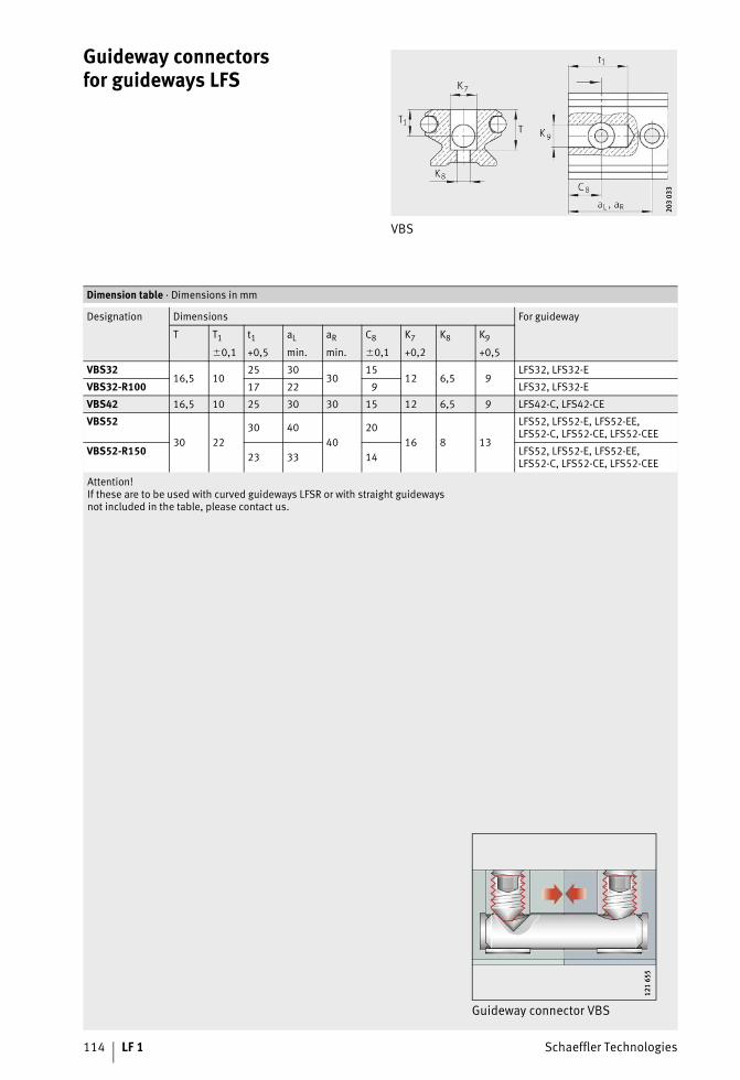
114 LF 1 Schaeffler Technologies
Guideway connectorsfor guideways LFS
VBS
203
033
203
033
Attention!If these are to be used with curved guideways LFSR or with straight guidewaysnot included in the table, please contact us.
Dimension table · Dimensions in mm
Designation Dimensions For guideway
T T1 t1 aL aR C8 K7 K8 K9
�0,1 +0,5 min. min. �0,1 +0,2 +0,5
VBS3216,5 10
25 3030
1512 6,5 9
LFS32, LFS32-E
VBS32-R100 17 22 9 LFS32, LFS32-E
VBS42 16,5 10 25 30 30 15 12 6,5 9 LFS42-C, LFS42-CE
VBS52
30 2230 40
4020
16 8 13
LFS52, LFS52-E, LFS52-EE,LFS52-C, LFS52-CE, LFS52-CEE
VBS52-R150 23 33 14 LFS52, LFS52-E, LFS52-EE,LFS52-C, LFS52-CE, LFS52-CEE
Guideway connector VBS
121
655
121
655

Schaeffler Technologies LF 1 115
End plate
ANS.LFS, ANS.LFS42-C, ANS.LFS86-C, ANS.LFS..-NZZ
121
433
121
433
ANS cannot be mounted on:LFS32-C: aL, aR � 28 mmLFS52-C: aL, aR � 40 mm.
Dimension table · Dimensions in mm
Designation Dimensions For guidewayb jB a s t N3 h h1 jh G
�
ANS.LFS20 15,4 – – 6 12 – 11 6,2 – M5 LFS20
ANS.LFS25 20 – – 5 7 – 14 4 7 M3 LFS25
ANS.LFS3230 –
–8
7 – 19 5 10 M4 LFS32
ANS.LFS32-C 15 12H13 – –
–
�6,5H13 LFS32-C
ANS.LFS32-F 26 11
6
–
– 95
M4 LFS32-F
ANS.LFS32-FH 22 9 9 7 M3 LFS32-FH
ANS.LFS32-N 26 11 – – 15 M4 LFS32-N
ANS.LFS42-C 35,5 17 – 8 7 – 18 8 – M4 LFS42-C
ANS.LFS5245 –
–10
10 – 30 7 15 M6 LFS52
ANS.LFS52-C 20 19H13 30 –
–
�11H13 LFS52-C
ANS.LFS52-F 42 21
8 10 – 169
M5
LFS52-F
ANS.LFS52-FH 37 20 6,5 LFS52-FH
ANS.LFS52-NZZ 42 21 – 24 LFS52-NZZ
ANS.LFS86-C 80 54,1 – 9 20 – 30 17,5 – M6 LFS86-C
ANS.LFS120 114 80 – 5 10 – 16 8 – M6 LFS120
ANS.LFS32-C, ANS.LFS-52-C (hollow section) ANS.LFS..-F (-FH)
121
589
121
589
121
435
121
435
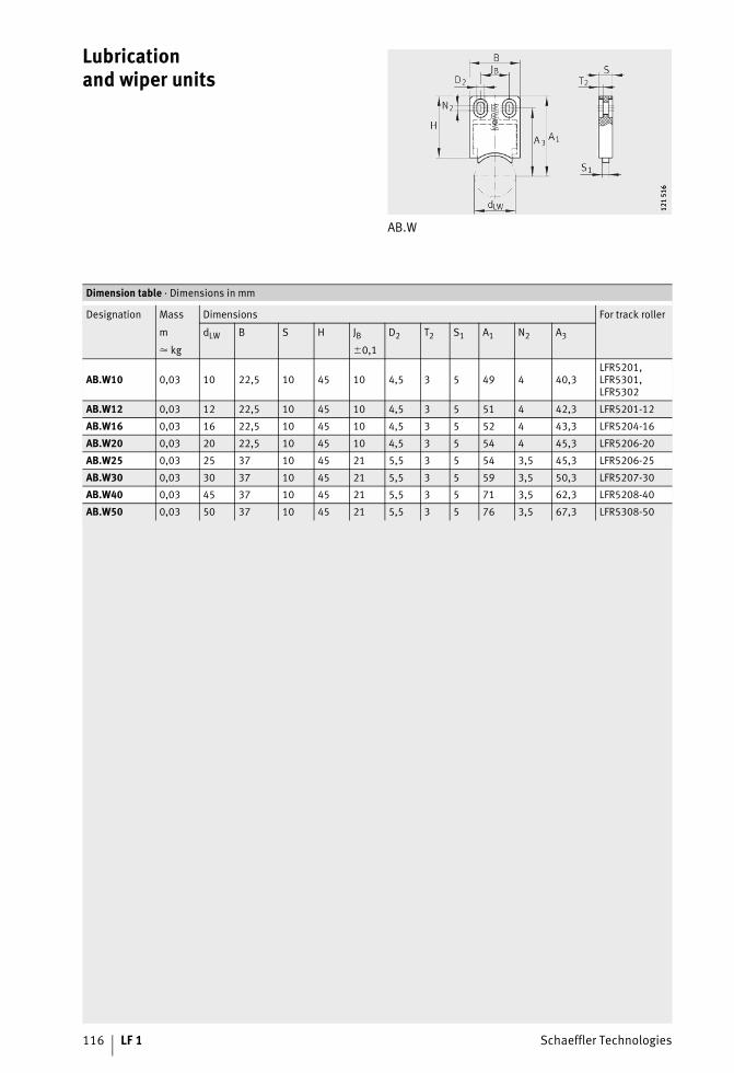
116 LF 1 Schaeffler Technologies
Lubricationand wiper units
AB.W
121
516
121
516
Dimension table · Dimensions in mm
Designation Mass Dimensions For track roller
m dLW B S H JB D2 T2 S1 A1 N2 A3
� kg �0,1
AB.W10 0,03 10 22,5 10 45 10 4,5 3 5 49 4 40,3LFR5201, LFR5301, LFR5302
AB.W12 0,03 12 22,5 10 45 10 4,5 3 5 51 4 42,3 LFR5201-12
AB.W16 0,03 16 22,5 10 45 10 4,5 3 5 52 4 43,3 LFR5204-16
AB.W20 0,03 20 22,5 10 45 10 4,5 3 5 54 4 45,3 LFR5206-20
AB.W25 0,03 25 37 10 45 21 5,5 3 5 54 3,5 45,3 LFR5206-25
AB.W30 0,03 30 37 10 45 21 5,5 3 5 59 3,5 50,3 LFR5207-30
AB.W40 0,03 45 37 10 45 21 5,5 3 5 71 3,5 62,3 LFR5208-40
AB.W50 0,03 50 37 10 45 21 5,5 3 5 76 3,5 67,3 LFR5308-50

Schaeffler Technologies LF 1 117
Lubricationand wiper units
AB ABView rotated 90°
121
254
121
254
121
255
121
255
1) Please contact us.
Dimension table · Dimensions in mm
Designation Mass Dimensions For carriage
m B T3 S A3 H A4 A5 K4
For screwsto DIN 7972
� kg
AB32 0,03 80 6 11 5 32 7 7 ST2,9LFL32-SF, LFL52-SF, LFL52-E-SF, LFDL32-SF, LFDL32-B1)
AB52 0,1 120 20 18 8,5 45,5 9,7 15 ST4,8LFL32-SF, LFL52-SF, LFL52-E-SF, LFDL32-SF, LFDL32-B
AB52-E 0,13 135 20 18 8,5 55 12 20,6 ST4,8 LFL32-SF, LFL52-SF, LFL52-E-SF
AB.LFLL32 0,03 80 6 11 5 32 7 7 ST2,9 LFLL32-SF1)
AB.LFLL52 0,1 120 20 18 8,5 45,5 9,7 15 ST4,8 LFLL52-SF

118 LF 1 Schaeffler Technologies
Cap wipers
AB.LFR
121
268
121
268
1) Observe the note on page 110.
Dimension table · Dimensions in mm
Designation Mass Dimensions For
m B A3 A4 N2 A6 L JL H1 K4 N1 track roller carriage
� kg �0,1 +0,1
AB.LFR50/8 0,02 31,6 25,9 15,6 2 6,4 51 28,5 15 M3 15 LFR50/8 LFCL25
AB.LFR5201 0,02 43,3 33,4 22,3 2 16 56 40 21,3 M3 20 LFR5201 LFCL42
AB.LFR5301 0,03 50 38,7 26 2 10,4 76 46 25 M3 20 LFR5301 LFCL86
AB.LFR53021) – 57 46 – 1,5 15,5 58 48 31 M3 – LFR5302 –
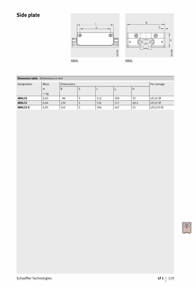
Schaeffler Technologies LF 1 119
Side plate
ABAL ABAL
121
257
121
257
121
256
121
256
Dimension table · Dimensions in mm
Designation Mass Dimensions For carriage
B S L JL Hm
� kg
ABAL32 0,03 86 3 112 100 32 LFL32-SF
ABAL52 0,04 130 5 136 117 49,5 LFL52-SF
ABAL52-E 0,05 145 5 186 167 55 LFL52-E-SF
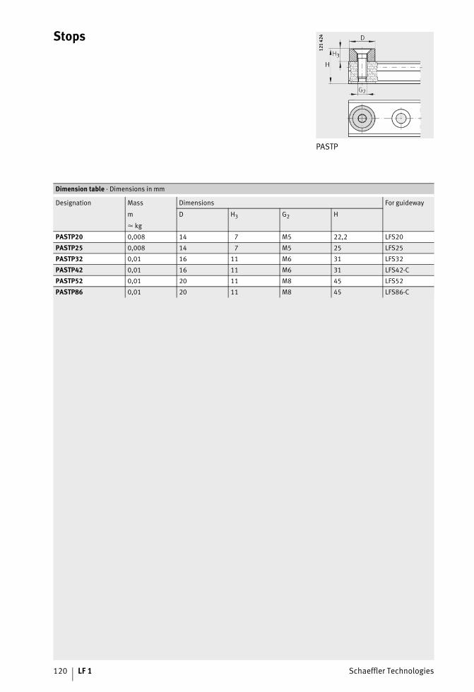
120 LF 1 Schaeffler Technologies
Stops
PASTP
121
424
121
424
Dimension table · Dimensions in mm
Designation Mass Dimensions For guideway
m D H3 G2 H
� kg
PASTP20 0,008 14 7 M5 22,2 LFS20
PASTP25 0,008 14 7 M5 25 LFS25
PASTP32 0,01 16 11 M6 31 LFS32
PASTP42 0,01 16 11 M6 31 LFS42-C
PASTP52 0,01 20 11 M8 45 LFS52
PASTP86 0,01 20 11 M8 45 LFS86-C

Schaeffler Technologies LF 1 121
Stops
PAH PAHView rotated 90°
121
260
121
260
0001
A445
0001
A445
Dimension table · Dimensions in mm
Designation Mass Dimensions For guideway
m B A1 S A6 D H H1 H3 A4 A5 Widthacrossflats
� kg W
PAH32 0,05 46 21 30 15 10 39 32 19 7 14 5 LFS32-C
PAH52 0,17 75 35 43 20 16 70,5 58 36,5 9,5 30 6 LFS52-C (-NZZ)

122 LF 1 Schaeffler Technologies
End cover
KA.LFS..-C KA.LFS..-M
121
234
121
234
121
247
121
247
Dimension table · Dimensions in mm
Designation Mass Dimensions For guideway
m b2 b1 S h1 h2
� kg
KA.LFS25-M 0,01 24,4 55,4 3 45,4 30,9 LFS25-M
KA.LFS32-C 0,01 31,4 23,4 3 19,4 – LFS32-C
KA.LFS32-M 0,012 31,4 75,4 3 59,9 46,4 LFS32-M
KA.LFS42-C 0,012 41,4 27,4 3 19,4 – LFS42-C
KA.LFS52-C 0,013 51,6 39,5 3 33,4 – LFS52-C
KA.LFS52-M 0,015 51,6 111,4 4 98 64,8 LFS52-M
KA.LFS86-C 0,015 85,6 70,4 3 33,4 – LFS86-C

Schaeffler Technologies LF 1 123
Slot closing strip
NAD
121
248
121
248
Dimension table · Dimensions in mm
Designation Mass Dimensions For guideway
m b b1 b2 h
� kg
NAD5�5,7 0,012 4,8 3 5,7 5,7 LFS25-M
NAD8�11,5 0,027 8,2 5,5 9,2 11,5 LFS32-M, LFS52-M
NAD5�5,7
0001
A186
0001
A186

124 LF 1 Schaeffler Technologies
Addresses
Germany Schaeffler Technologies AG & Co. KGLinear Technology DivisionBerliner Straße 13466424 Homburg (Saar)Tel. +(49) 6841 701-0Fax +(49) 6841 [email protected]
Argentina Schaeffler Argentina S.r.l.Av. Alvarez Jonte 1938C1416EXR Buenos AiresTel. +(54) 11 40 16 15 00Fax +(54) 11 45 82 33 [email protected]
Australia Schaeffler Australia Pty Ltd.Level 1, Bldg. 8,Forest Central Business Park49 Frenchs Forest RoadFrenchs Forest, NSW 2086Tel. +(61) 2 8977 1000Fax +(61) 2 9452 [email protected]
Austria Schaeffler Austria GmbHFerdinand-Pölzl-Straße 22560 Berndorf-St. VeitTel. +(43) 2672 202-0Fax +(43) 2672 [email protected]
Belarus Schaeffler Technologies AG & Co. KGRepräsentanz WeißrußlandOdoewskogo 117, office 317220015 MinskTel. +(375) 17 269 94 81Fax +(375) 17 269 94 [email protected]
Belgium Schaeffler Belgium S.P.R.L./B.V.B.A.Avenue du Commerce, 381420 Braine L’AlleudTel. +(32) 2 3 89 13 89Fax +(32) 2 3 89 13 [email protected]
Bosnia-Herzegovina
Schaeffler Hrvatska d.o.o.Ogrizovićeva 28b10000 ZagrebCroatiaTel. +(385) 1 37 01 943Fax +(385) 1 37 64 [email protected]
Brazil Schaeffler Brasil Ltda.Av. Independência, 3500-ABairro Éden 18087-101 Sorocaba, SPTel. +(55) 0800 11 10 29Fax +(55) 15 33 35 19 [email protected]
Bulgaria Schaeffler Bulgaria OODDondukov-Blvd. No 62Eing. A, 6. Etage, App. 101504 SofiaTel. +(359) 2 946 3900
+(359) 2 943 4008Fax +(359) 2 943 [email protected]

Schaeffler Technologies LF 1 125
Canada Schaeffler Canada Inc.2871 Plymouth DriveOakville, ON L6H 5S5Tel. +(1) 905 8 29 27 50
+(1) 800 263 4397 (Toll Free)Fax +(1) 905 8 29 25 [email protected]
China Schaeffler Trading (Shanghai) Co., Ltd.No. 1 Antuo Road (west side of Anhong Road), Anting, Jiading District201804 ShanghaiTel. +(86) 21 3957 6500Fax +(86) 21 3959 [email protected]
Croatia Schaeffler Hrvatska d.o.o.Ogrizovićeva 28b10000 ZagrebTel. +(385) 1 37 01 943Fax +(385) 1 37 64 [email protected]
CzechRepublic
Schaeffler CZ s.r.o.Průběžná 74a100 00 Praha 10Tel. +(420) 267 298 111Fax +(420) 267 298 [email protected]
Denmark Schaeffler Danmark ApSJens Baggesens Vej 90P8200 Aarhus NTel. +(45) 70 15 44 44Fax +(45) 70 15 22 [email protected]
Estonia Schaeffler TechnologiesRepräsentanz BaltikumDuntes iela 23a1005 RigaLatviaTel. +(371) 7 06 37 95Fax +(371) 7 06 37 [email protected]
Finland Schaeffler Finland OyLautamiehentie 302770 EspooTel. +(358) 207 36 6204Fax +(358) 207 36 [email protected]
France Schaeffler France SAS93 route de Bitche, BP 3018667506 Haguenau CedexTel. +(33) 3 88 63 40 40Fax +(33) 3 88 63 40 [email protected]
Great Britain Schaeffler (UK) Ltd.Forge Lane, MinworthSutton Coldfield B76 1APTel. +(44) 121 3 13 58 70Fax +(44) 121 3 13 00 [email protected]
Hungary Schaeffler Magyarország Ipari Kft.Rétköz utca 5.1118 BudapestTel. +(36) 1 4 81 30 50Fax +(36) 1 4 81 30 [email protected]
Italy Schaeffler Italia S.r.l.Via Dr. Georg Schaeffler, 728015 MomoTel. +(39) 0321 929 211Fax +(39) 0321 929 [email protected]
Japan Schaeffler Japan Co., Ltd.New Stage Yokohama 1-1-32Shinurashima-cho222-0031 YokohamaTel. +(81) 45 274 8211Fax +(81) 45 274 [email protected]
Korea Schaeffler Korea Corporation14F, Kyobo life insurance Bldg.Seoul, 110-714Tel. +(82) 2 311 3440Fax +(82) [email protected]
126 LF 1 Schaeffler Technologies
Addresses
Latvia Schaeffler TechnologiesRepräsentanz BaltikumDuntes iela 23a1005 RigaTel. +(371) 7 06 37 95Fax +(371) 7 06 37 [email protected]
Lithuania Schaeffler TechnologiesRepräsentanz BaltikumDuntes iela 23a1005 RigaLatviaTel. +(371) 7 06 37 95Fax +(371) 7 06 37 [email protected]
Mexico INA Mexico, S.A. de C.V.Rodamientos FAG, S.A. de C.V.Henry Ford #141Col. BondojitoDeleg. Gustavo A. Madero07850 Mexico D.F.Tel. +(52) 55 5062 6085Fax +(52) 55 5739 [email protected]
Netherlands Schaeffler Nederland B.V.Gildeweg 313771 NB BarneveldTel. +(31) 342 40 30 00Fax +(31) 342 40 32 [email protected]
New Zealand Schaeffler New Zealand(Unit R, Cain Commercial Centre)20 Cain Road1135 PenroseTel. +(64) 9 583 1280
+(64) 021 324 247 (Call out fee applies)
Fax +(64) 9 583 [email protected]
Norway Schaeffler Norge ASGrenseveien 107B0663 OsloTel. +(47) 23 24 93 30Fax +(47) 23 24 93 [email protected]
Poland Schaeffler Polska Sp. z.o.o.Budynek Eul. Szyszkowa 35/3702-285 WarszawaTel. +(48) 22 8 78 41 20Fax +(48) 22 8 78 41 [email protected]
Portugal INA Rolamentos Lda.Arrábida Lake TowersRua Daciano Baptista Marques Torre C, 181, 2º piso4400-617 Vila Nova de GaiaTel. +(351) 22 5 32 08 00Fax +(351) 22 5 32 08 [email protected]
Romania S.C. Schaeffler Romania S.R.L.Aleea Schaeffler Nr. 3507055 Cristian/BrasovTel. +(40) 268 505000Fax +(40) 268 [email protected]
Russia Schaeffler Rußland GmbHPiskarevsky prospect, 2, build.3, letter ABC „Benua“, office 207195027 St. PetersburgTel. +(7) 812 633 3644Fax +(7) 812 633 [email protected]
Schaeffler RußlandLeningradsky Prospekt 47, Bau 3Business-Center Avion125167 MoscowTel. +(7) 495 73776-60Fax +(7) 495 [email protected]

Schaeffler Technologies LF 1 127
Serbia Schaeffler TechnologiesRepräsentanz SerbienBranka Krsmanovica 1211118 BeogradTel. +(381) 11 308 87 82Fax +(381) 11 308 87 [email protected]
Singapore Schaeffler (Singapore) Pte. Ltd.151 Lorong Chuan, #06-01New Tech Park, Lobby A556741 SingaporeTel. +(65) 6540 8600Fax +(65) 6540 [email protected]
SlovakRepublic
Schaeffler Slovensko, spol. s.r.o.Ulica Dr. G. Schaefflera 102401 Kysucké Nové MestoTel. +(421) 41 4 20 59 11Fax +(421) 41 4 20 59 [email protected]
Slovenia Schaeffler Slovenija d.o.o.Glavni trg 17/b2000 MariborTel. +(386) 2 22 82 070Fax +(386) 2 22 82 [email protected]
South Africa Schaeffler South Africa (Pty.) Ltd.1 End Street Ext. Corner Heidelberg Road2000 JohannesburgTel. +(27) 11 225 3000Fax +(27) 11 334 [email protected]
Spain Schaeffler Iberia, s.l.u.C/ Foment, 2Polígono Ind. Pont Reixat08960 Sant Just DesvernTel. +(34) 93 4 80 34 10Fax +(34) 93 3 72 92 [email protected]
Sweden Schaeffler Sverige ABCharles gata 10195 61 ArlandastadTel. +(46) 8 59 51 09 00Fax +(46) 8 59 51 09 [email protected]
Switzerland Schaeffler Schweiz GmbHBadstraße 148590 RomanshornTel. +(41) 71 4 66 66 66Fax +(41) 71 4 66 63 [email protected]
Turkey Schaeffler Rulmanlari Ticaret Limited SirketiAydin Sokak Dagli Apt. 4/41. Levent34340 IstanbulTel. +(90) 212 2 79 27 41
+(90) 212 280 77 98Fax +(90) 212 281 66 45
+(90) 212 280 94 [email protected]
Ukraine Schaeffler TechnologiesRepresentative Office UkraineJilyanskayastr. 75, 5-er StockBusiness Center «Eurasia»01032 KiewTel. +(380) 44 520 13 80Fax +(380) 44 520 13 [email protected]
USA Schaeffler Group USA Inc.308 Springhill Farm RoadCorporate OfficesFort Mill, SC 29715Tel. +(1) 803 548 8500Fax +(1) 803 548 [email protected]

Schaeffler Technologies AG & Co. KG
Linear Technology Division Berliner Straße 134 66424 Homburg/Saar (Germany) Internet www.ina.com E-mail [email protected]
In Germany: Phone 0180 5003872 Fax 0180 5003873
From other countries: Phone +49 6841 701-0 Fax +49 6841 701-2625M
ATN
R 03
2918
356
-000
0 / L
F 1
/ GB
-D /
2016
062.
5 / P
rint
ed in
Ger
man
y by
moh
n


![ÁNNO IV Lisboa, de Peverez,-o de Jí C0R J]11:{$I }1Ji](https://img.pdfslide.net/doc/110x75/62d7b3a14b4009541a7f05df/nno-iv-lisboa-de-peverez-o-de-j-c0r-j11i-1ji.jpg)