Embed Size (px)
Citation preview
For business purposes only. Unauthorized access, use, distribution, or modification of Union Pacific computer systems or theircontent is prohibited by law.
Union Pacific Rules
Track Welding Rules and Procedures
Effective May 2, 2016Includes Updates as of May 2, 2016PB-21321
100.0: GENERAL INSTRUCTIONS101.0: SAFETY102.0: ELECTRIC WELDING103.0: OXY-FUEL EQUIPMENT104.0: EQUIPMENT105.0: WELDING RAIL ENDS106.0: WELDING SWITCH POINTS107.0: FROGS: GENERAL108.0: REPAIRING CARBON TURNOUT AND CROSSING (DIAMOND) FROGS109.0: REPAIRING MANGANESE TURNOUT AND CROSSING FROGS110.0: THERMITE WELDS: RAILTECH-BOUTET111.0: THERMITE WELDS: ORGO-THERMIT112.0: ELECTRIC FLASH-BUTT WELDING113.0: SWITCH MAINTENANCE GRINDING114.0: DEFINITIONSAPPENDIX: APPENDIX
Union Pacific Rules Track Welding Rules and Procedures
100.0: GENERAL INSTRUCTIONS
100.1: Employee Responsibilities
Following instructions that differ from the Union Pacific Railroad standards, FRA guidelines and rules outlined in the trackwelding rules could be potentially harmful to the safe operation of the railroad and must be brought to the attention of theManager of Track Welding.
Where Union Pacific Railroad rules are more restrictive than the FRA, Union Pacific Railroad rules will be followed.
100.1: Employee Responsibilities100.1.1: Carry Instructions100.2: List of Assigned Duties100.2.1: Electric Welding100.2.2: Thermite Welding100.2.3: Electric Flash-Butt Welding100.2.4: Oxy-Fuel Equipment Operation100.2.5: Abrasive Wheel Cutting and Grinding100.2.6: Reporting100.2.7: Other Duties100.3: Qualifications - Welders/Helpers100.3.1: Re-qualification100.4: Rail Identification100.4.1: Rail Branding100.4.2: Rail Stamping100.4.3: Hydrogen Elimination100.4.4: Rail Chemistry Identification100.5: Component Installation100.5.1: Component Installation - Marking100.6: Reference Marks100.7: Rail Bond Wire100.8: Torch Cut Rail Ends and Bolt Holes100.8.1: Torch Cut Rail Ends100.8.2: Torch Cut Holes100.9: Deburring Bolt Holes100.10: Guardrails100.11: Electric Arc Welded Rail Ends
Rule Updated Date
May 2, 2016
^Top
100.1.1: Carry Instructions
Welding managers and supervisors, track managers and supervisors, track inspectors, track maintenance foremen, trackwelders and helpers and grinder operators must have a current copy of the track welding rules as described in thisdocument: Track Welding Rules and Procedures for Inspecting, Welding, and Grinding of Rail and Track Components, andreadily available.
Rule Updated Date
May 2, 2016
^Top
100.2: List of Assigned Duties
Rule Updated Date
March 1, 2007
^Top
100.2.1: Electric Welding
Rule Updated Date
March 1, 2007
^Top
100.2.2: Thermite Welding
Repair battered or chipped rail ends.Repair worn or damaged rail bound manganese turn-out frogs.Repair worn or damaged bolted rigid frogs.Repair worn or damaged self-guarded manganese frogs.Repair spring frogs (only as allowed in rules).Repair crossing frogs.Repair switch points (only as allowed in rules).
Install standard gap welds - various manufacturers.Install wide gap welds - various manufacturers.
Rule Updated Date
May 2, 2016
^Top
100.2.3: Electric Flash-Butt Welding
Rule Updated Date
March 1, 2007
^Top
100.2.4: Oxy-Fuel Equipment Operation
Rule Updated Date
March 1, 2007
^Top
100.2.5: Abrasive Wheel Cutting and Grinding
Rule Updated Date
March 1, 2007
^Top
100.2.6: Reporting
Install head repair welds - various manufacturers.
Operate In-Track Welders.
Operate all oxy-fuel cutting equipment.Operate all oxy-fuel heating equipment.
Operate all grinding equipment used for preventive grinding.Operate all grinding equipment used in track welding repairs.Operate all abrasive saws used to cut rail.
Complete all timekeeping and production reports as required.Complete "Cut-in/Cut-out" and "Service Failure" reports, if applicable.
Rule Updated Date
May 2, 2016
^Top
100.2.7: Other Duties
Rule Updated Date
March 1, 2007
^Top
100.3: Qualifications - Welders/Helpers
Rule Updated Date
May 2, 2016
^Top
100.3.1: Re-qualification
Rule Updated Date
May 2, 2016
^Top
Tamp ties, as necessary, for repair longevity and safe train operation.Replace and /or tighten track and frog bolts as part of repair or when necessary for safe train operation.Install replacement rail and insulated joint plugs as required before welding.
Must meet Commercial Drivers License (CDL) and Department of Transportation (DOT) requirements for specificposition.At least one employee at the work location must be qualified under FRA 217 (a)(b).Must be qualified by Manager of Track Welding or Welding Supervisor to use oxy-fuel and welding equipment.Employees must be qualified to perform job specific welding processes.Qualification will consist of training and skills assessment.Qualification period is 3 years as required by Union Pacific Railroad.Prior to qualification, employee may work under the direct supervision of a qualified employee.
Every 3 years, employees shall be re-qualified in the use of oxy-fuel, welding equipment and welding processes.
100.4: Rail Identification
Rule Updated Date
May 2, 2016
^Top
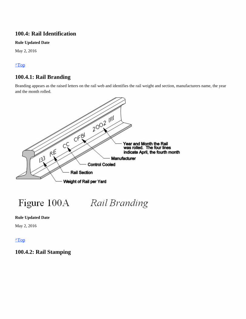
100.4.1: Rail Branding
Branding appears as the raised letters on the rail web and identifies the rail weight and section, manufacturers name, the yearand the month rolled.
Rule Updated Date
May 2, 2016
^Top
100.4.2: Rail Stamping
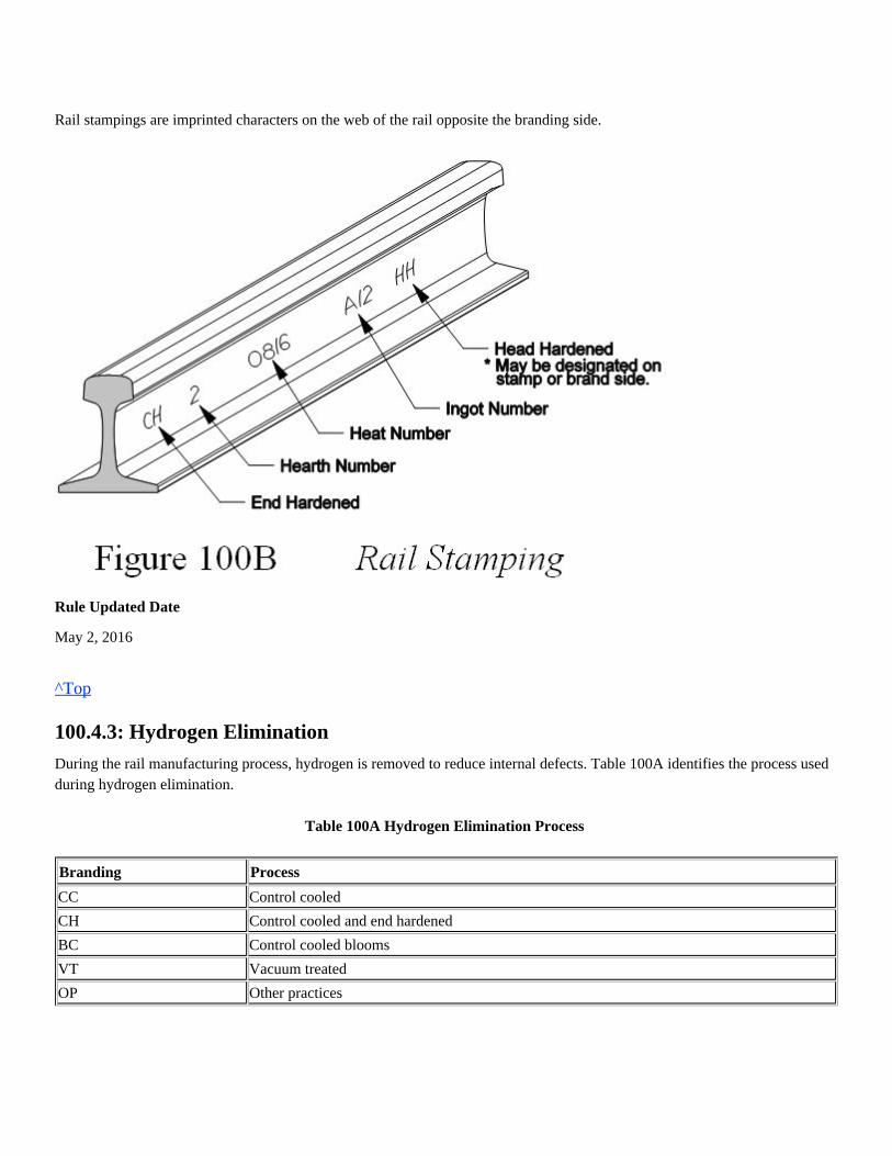
Rail stampings are imprinted characters on the web of the rail opposite the branding side.
Rule Updated Date
May 2, 2016
^Top
100.4.3: Hydrogen Elimination
During the rail manufacturing process, hydrogen is removed to reduce internal defects. Table 100A identifies the process usedduring hydrogen elimination.
Table 100A Hydrogen Elimination Process
Branding Process
CC Control cooled
CH Control cooled and end hardened
BC Control cooled blooms
VT Vacuum treated
OP Other practices
Rule Updated Date
May 2, 2016
^Top
100.4.4: Rail Chemistry Identification
Rail chemistry determines specific maintenance and welding requirements.(Refer to Table s 100B and Table 100C to determine whether rail is alloy or non-alloy)
Table 100B Alloy Rail
ALLOY RAIL
Manufacturer Branding Stamping Chemistry/Type
CF&I CROMO Chrome/Molybdenum
CF&I HI SI High Silicon
W-P (WHEELING PITT) WR Chrome/Silicon
W-P (WHEELING PITT) CR Chrome/Silicon
KLOCKNER-AL Blank Chrome/Vanadium
KRUPP-AL Blank Chrome/Vanadium
TYHSSEN-AL Blank Chrome/Vanadium
STH Blank Chrome/Vanadium
Table 100C Non-Alloy Rail
NON-ALLOY RAIL
BETHLEHEM STEEL FT Fully Heat Treated
BETHLEHEM STEEL HH Head Hardened
BETHLEHEM STEEL MH Standard Strength
BRITISH FT Head Hardened
CF&I (HH on glued tag) IS Head Hardened
CF&I H Head Hardened
CF&I DH390 Head Hardened
CF&I IS Standard Strength
CF&I SS Standard Strength
COLORADO Blank Standard Strength
HAY (HAYANGE) Blank Head Hardened
ILLINOIS Blank Standard Strength
INLAND Blank Standard Strength
ISG (INTERNATIONAL STEEL GROUP) Blank Standard Strength
ISG HH (INTERNATIONAL STEEL GROUP) Blank Head Hardened
KLOCKNER Blank Standard Strength
KRUPP Blank Standard Strength
MT (MITTAL USA) Blank Standard Strength
MT HH (MITTAL USA) Blank or IS or HH Head Hardened
MMRA Blank Standard Strength
MMRA HH Blank Head Hardened
NIPPON DH340 Head Hardened
NIPPON DH370 Head Hardened
NIPPON HE370 Head Hardened
NIPPON HE400 Head Hardened
NIPPON HEX Head Hardened
NKK NHH Head Hardened
NKK SP Head Hardened
NKK HH Blank Head Hardened
PST (PENNSYLVANIA STEEL TECH) Blank Standard Strength
PST HH (PENNSYLVANIA STEEL TECH) Blank Head Hardened
RMSM DH390 Head Hardened
RMSM or ERMS SS Standard Strength
RMSM or ERMS IS HH (IHHS) Head Hardened
RMSM HCP Head Hardened
RMSM or ERMS OPC Head Hardened
RMSM or ERMS Blank Standard Strength
SDI (STEEL DYNAMICS) Blank Standard Strength
TENNESSEE Blank Standard Strength
THYSSEN HH Head Hardened
THYSSEN Blank Standard Strength
TZ (CZECH) SS Standard Strength
W-P (WHEELING PITT) MH Standard Strength
Rule Updated Date
May 2, 2016
^Top
100.5: Component Installation
Rule Updated Date
May 2, 2016
^Top
100.5.1: Component Installation - Marking
The installation date should be marked with a "white" metal marker on the following track components:
The installation date will be used to verify warranty claims and track component longevity.
Rule Updated Date
May 2, 2016
^Top
100.6: Reference Marks
Placing rail reference marks is a method of controlling the amount of rail added or subtracted in CWR territory. Referencemarks must be utilized prior to cutting CWR for any reason.In the case of a rail separation, pull-apart , defect repair, other rail change out and track panel installation, reference marksshould always indicate the original distance between the marks before the rail break or pull-apart occurred.
The types of reference marks that are used to manage the CWR events are:
For complete instructions including examples, refer to the current version of the Engineering Track Maintenance FieldHandbook.
Rule Updated Date
May 2, 2016
FrogsGuard RailsSpring Frog RetardersSwitch PointsStock RailsI-Bonds
Spanning reference marks: Used for service failures, pull-aparts, detector car defects, track panels less than 80'. Refer toSection 7 (7.9.3 Placing Spanning Reference Marks) in the Engineering Track Maintenance Field Handbook (ETMFH).Pull back reference marks: Used for rail change out greater than 80' or less than or equal to 360' and track panels greaterthan 80' or less than or equal to 360'. Refer to Section 7 (7.9.4 Placing Pull Back Reference Marks) in the EngineeringTrack Maintenance Field Handbook (ETMFH).Match marks are used when rail change out is greater than 360'. Refer to Section 4 - (4.5.1A Monitor Rail Movement)in the Engineering Track Maintenance Field Handbook (ETMFH).
^Top
100.7: Rail Bond Wire
Remove rail bond wires by grinding only.
Do not electric arc weld bond wires onto rail.
Rule Updated Date
May 2, 2016
^Top
100.8: Torch Cut Rail Ends and Bolt Holes
Rule Updated Date
May 2, 2016
^Top
100.8.1: Torch Cut Rail Ends
Torch cut rail ends must be re-cut with a rail saw before train movement is allowed.Thermite or electric flash butt welding of torch cut rail ends is prohibited.Rail ends cut with an oxy-fuel torch will be trimmed back no less than 1/4 inch if done within 15 minutes of the initial torchcut.
If rail end cannot be re-cut with a rail saw within 15 minutes of the torch cut, an additional 2 inches of rail must be removed toget beyond the thermal heat cracks.
Visually inspect rail ends for split web and other defects after saw cutting.
Rule Updated Date
May 2, 2016
^Top
Use of a chisel or hot cut to remove rail bonds is prohibited.
All indication of torch cut must be removed.
A single rail end must be cut square both vertically and horizontally.Rail ends being thermite welded that have a combined deviation of more than 1/8 inch must be re-cut.
100.8.2: Torch Cut Holes
Rail with torch cut holes are prohibited in any track.Any hole cut in rail must be cut back with a rail saw no less than 2 inches from the torch cut.
Rule Updated Date
May 2, 2016
^Top
100.9: Deburring Bolt Holes
Bolt holes must be deburred and beveled immediately after drilling is completed using the appropriate grinding tool.
Rule Updated Date
May 2, 2016
^Top
100.10: Guardrails
Follow these guardrail repair requirements:
Rule Updated Date
March 1, 2007
^Top
100.11: Electric Arc Welded Rail Ends
On main tracks and siding's, rail ends that have been previously electric arc welded are prohibited from being thermite weldedon rail manufactured after 1975 and on alloy rail.
Rule Updated Date
May 2, 2016
Bolt holes must be deburred before rail ends are welded.Visually inspect all bolt holes for cracks before welding.
Do not weld a guardrail face in the field.Replace worn or damaged guardrails.Use shop repaired or reconditioned guardrails in any track only after they have been inspected and approved for use.

^Top
Union Pacific Rules Track Welding Rules and Procedures
101.0: SAFETY
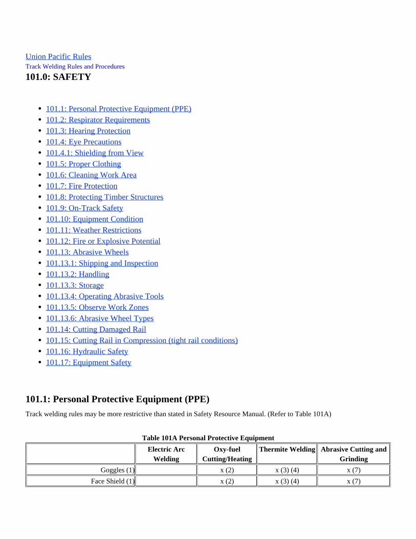
101.1: Personal Protective Equipment (PPE)
Track welding rules may be more restrictive than stated in Safety Resource Manual. (Refer to Table 101A)
Table 101A Personal Protective Equipment
Electric ArcWelding
Oxy-fuelCutting/Heating
Thermite Welding Abrasive Cutting andGrinding
Goggles (1) x (2) x (3) (4) x (7)
Face Shield (1) x (2) x (3) (4) x (7)
101.1: Personal Protective Equipment (PPE)101.2: Respirator Requirements101.3: Hearing Protection101.4: Eye Precautions101.4.1: Shielding from View101.5: Proper Clothing101.6: Cleaning Work Area101.7: Fire Protection101.8: Protecting Timber Structures101.9: On-Track Safety101.10: Equipment Condition101.11: Weather Restrictions101.12: Fire or Explosive Potential101.13: Abrasive Wheels101.13.1: Shipping and Inspection101.13.2: Handling101.13.3: Storage101.13.4: Operating Abrasive Tools101.13.5: Observe Work Zones101.13.6: Abrasive Wheel Types101.14: Cutting Damaged Rail101.15: Cutting Rail in Compression (tight rail conditions)101.16: Hydraulic Safety101.17: Equipment Safety

Safety Glasses x x x (3) (4) x (7)
Welding Hood (1) x x **
Hearing Protection x x x x
Leather Welding Gloves x x x (8)
Work Gloves x (8) x
Welding Jacket (5) x x x x
Respirator (6) x x x
Leggings * x x
Minimum Requirements
(1) Refer to Rule 101.4 Eye Precautions for proper shading.
(2) Wrap-around face shield with goggles or safety glasses (one must be shade #5). (Mono-goggle XTR shade #5 with safety glasses can be used as an alternative)
(3) Wrap-around face shield with goggles or safety glasses (one must be shade #5) when monitoring thermite weld preheat and pouring process.
(4) Wrap-around face shield with goggles or safety glasses are required for removing molds and cleaning weld. (This includes the mono-goggle XTR with safety glasses)
(5) Welding sleeves may be worn in place of jackets to protect arms (including thermite breakdown).
(6) Refer to current respiratory policy in the Safety Resource Manual for minimum requirements.
(7) Wrap-around face shield with goggles or safety glasses (shade #5 lens must be worn).NOT
(8) Leather welding gloves are required while removing the clamp, jackets, and slag pan. (Gloves are required while packing the molds)
* Both leggings are required to be worn.** Approved welding hood with grind mode can be used as an alternative to required eye protection when abrasive grinding.
Rule Updated Date
May 2, 2016
^Top
101.2: Respirator Requirements
Respirator use requirements apply to welders performing hazardous activities or tasks.
Information on the Union Pacific Respiratory Protection Program can be found in the Safety Resource Manual - Section E.This section provides information on job tasks requiring the use of respirators. Respirators must be selected from the currentUPRR Safety Resource Manual, Section E - Appendix B and the ORR Safety Products Catalog.
These two documents can be accessed online through the UPRR employee homepage under Work Place Safety at:
http://home.www.uprr.com/emp/operating/she/safety/index.shtml
Employees performing activities or tasks that require a respirator must at least wear the minimum level of respiratoryprotection listed under the column in the respiratory protection policy. A respirator offering a higherMinimum Respirator Typeprotection factor is listed under the column.Other Approved Respirator Types Carbon Arc Cutting (CAC) and welding repairs on frogs, crossing diamonds or other track components containing more than2% manganese require use of a respirator. If a half-face air-purifying respirator is used, a track fan (380-0085 axial blower)must also be used. If a powered air-purifying respirator (PAPR) is used, the track fan is not required but is recommended forbetter visibility
Rule Updated Date
May 2, 2016
^Top
101.3: Hearing Protection
Approved hearing protection must be worn when using powered equipment including:
Rule Updated Date
March 1, 2007
^Top
101.4: Eye Precautions
All persons performing or observing welding, cutting and heating operations must wear proper eye protection and otherpersonal protective equipment. They must not look at an oxy-fuel flame or electric arc unless properly protected and must warnothers against looking at the flame or arc.
Refer to Table 101B below to determine minimum shade requirements of eye protection performing track welding, heating orcutting operations.
Table 101B Minimum Shade Requirements
Welding Operation Minimum Lens Shade
Shielded metal arc welding electrodes
Electric arc weldingAbrasive wheel cutting or grindingOxy-fuel or other fuel-gas equipmentPneumatic toolsHydraulic toolsGasoline powered tools
101214
Flux-cored arc welding (5/64 inch wire) 12
Carbon Arc Cutting/Gouging - for most applications 12
14
Oxy-fuel welding, cutting ahd heating 5
Cracked filter glasses (lens shade) must be replaced immediately. Shade numbers of filter plates are not additive. For example,a Number 6 and Number 8 filter do not have the same effective density as a Number 14 filter.
Rule Updated Date
May 2, 2016
^Top
101.4.1: Shielding from View
Welders must warn others to protect their eyes and use shields to prevent injuries and fires.
Rule Updated Date
March 1, 2007
^Top
101.5: Proper Clothing
When electric arc welding, carbon arc cutting, or oxy-fuel cutting; heating or welding; wear approved hearing protection,approved footwear, leather welding gloves and flame resistant clothing.
Also wear, at a minimum, an approved full welding jacket or welding sleeves with approved welding vest.When using a PAPR welding helmet, the shroud must be attached to the welding helmet and functional.
protective outerwear such as leather aprons, leather leggings, spats, welding jackets or welding sleeves shall beAdditionalworn for any application where clothing or body is in danger of being exposed to sparks or hot slag. Arms must be covered;
Up to and including 5/32 inch diameter3/16 to 1/4 inch diameter5/16 to 3/8 inch diameter
Large diameter carbon electrodes
Protects the skin from infrared and ultraviolet radiation and covers the arms.Reduces the possibility of catching fire.Has all buttons and snaps fastened.Has sleeves and pockets secured against sparks or slag.Is free of oil or grease.Is without cuffs.
short sleeved shirts are not acceptable.All buttons on jackets must be buttoned. Sleeves and pockets must be secured against sparks or hot slag.
When abrasive wheel cutting or grinding, arms must be fully covered with an approved welding jacket or welding sleeves.
Do not carry lighters or matches during hot work operations.
Rule Updated Date
May 2, 2016
^Top
101.6: Cleaning Work Area
Do not use gloved or bare hands to brush slag or metal from material being welded or cut.
Rule Updated Date
March 1, 2007
^Top
101.7: Fire Protection
Follow instructions in the UPRR Fire Protection Policy and Guidelines document and the Engineering Department Fire Prevention
Plan, which are available in the Safety Resource Manual.
Rule Updated Date
May 2, 2016
^Top
101.8: Protecting Timber Structures
Before leaving the work site, the employee in charge must ensure that no fire or fire hazard exists.If fire risk is high when completing the hot work task, you must adhere to all requirements as written in the Engineering FirePrevention Plan which includes:
Rule Updated Date
May 2, 2016
If a potential fire hazard exists, one person must remain at the job site for at least 2 hours after work is completed towatch for signs of smoke or fire.This person must have at least 5 gallons of water, a round-nose shovel and communications capable of calling for help.
^Top
101.9: On-Track Safety
Refer to Chief Engineer Instruction Bulletin 136.
This bulletin explains the On-Track Safety requirements for all roadway workers. The instructions in this bulletin conform tothe FRA regulations for roadway worker protection. The purpose of this bulletin is to prevent accidents and injuries fromrailroad cars, locomotives, and roadway machines striking roadway workers and machines.
Rule Updated Date
March 1, 2007
^Top
101.10: Equipment Condition
Inspect all equipment and ensure it is free of defects and in proper working condition.
Rule Updated Date
March 1, 2007
^Top
101.11: Weather Restrictions
Electric arc or thermite welding in extremely wet weather is prohibited.
An approved welding tent with a solid top can be used as long as weather and wind restrictions are met.
Note: Mesh top tent without solid top cover in place cannot be used in wet weather conditions.Note: A welding tent will not be used for cutting, grinding, or welding on track components containing more than 2%manganese. ESCO welding tent store stock item number: 380-7895 IRS welding tent store stock item number: 380-7890
If ground is covered with snow; all snow must be removed from welding and disposal areas before starting the thermitewelding process.
Do not run welding cables or electric cords through water or allow lying in standing water.Do not wear wet gloves while operating electrical equipment.
In rain, sleet, snow or mist.lightIn wind conditions as long as tent can be maintained in place and function as intended.light
An anemometer is required to determine wind speed
Rule Updated Date
May 2, 2016
^Top
101.12: Fire or Explosive Potential
Welding, cutting or heating on piston heads, hollow castings, or containers such as drums, barrels or tanks is prohibited.
Rule Updated Date
May 2, 2016
^Top
101.13: Abrasive Wheels
Rule Updated Date
March 1, 2007
^Top
101.13.1: Shipping and Inspection
Do not use abrasive wheels if they are:
Rule Updated Date
May 2, 2016
Do not begin the thermite weld process during light rain, sleet, snow or mist unless entire process can be protected fromthe wet weather.All precautions must be taken to avoid injury and defective weld, if welding process is already in progress.
When abrasive wheels are received, the original shipping container must be inspected for damage or moisture.If container damage is observed, the abrasive wheels must be inspected. Any abrasive wheel that is damaged orsuspected of being damaged must not be accepted and/or put into service.
Chipped, cracked, warped or brokenWater or oil soaked
^Top
101.13.2: Handling
Rule Updated Date
March 1, 2007
^Top
101.13.3: Storage
Abrasive wheels shipped on pallets may remain stored on pallets until ready to be used.
Rule Updated Date
March 1, 2007
^Top
101.13.4: Operating Abrasive Tools
All abrasive wheels are breakable and therefore care must be exercised in handling and storage to prevent damage.
Abrasive wheels in storage must not be exposed to water or other solvents.Abrasive wheels in storage must not be exposed to temperature or humidity conditions that cause condensation on thewheels.Suitable racks, bins or boxes shall be provided to store the various types of abrasive wheels.Abrasive wheels in storage shall be rotated so oldest wheels will be used first.Most abrasive wheel manufacturers recommend a shelf life of two years for properly stored abrasive wheels.
Wear all required PPE. (Refer to Tables 101A and 101B).Adhere to all Union Pacific fire prevention policies when operating abrasive wheel equipment. This includes usingspark guards as necessary and having the minimum number of round nose shovels and water as per the fire preventionplan.Spindle speed of grinder or rail saw must be checked periodically to ensure it is operating at its optimum and that it doesnot exceed the maximum operating speed marked on the abrasive wheel.Hydraulic powered cutting and grinding equipment and hydraulic power sources shall be periodically tested to ensureproper hydraulic pressure and flow.Blotters must be used between flanges and abrasive wheel/stone surface to ensure uniform distribution of flangepressure. Flanges must be the same size.The blotters shall cover the entire contact area at the wheel/stone flanges.
. The RPM rating of abrasiveOnly Union Pacific approved abrasive cut-off wheels and grinding stones may be usedwheels/stones must the RPM rating of the power equipment that is being used.meet or exceed
All abrasive wheels shall be used only on machines provided with safety guards with the following exception:
Rule Updated Date
May 2, 2016
^Top
101.13.5: Observe Work Zones
Adhere to the following work zones when operating abrasive wheel equipment.
Any employee not operating cutting or grinding equipment must not stand closer than 15 feet from equipment.
Rule Updated Date
March 1, 2007
^Top
101.13.6: Abrasive Wheel Types
Abrasive cutoff wheels and grinding stones have limitations and must be handled and used with care to prevent damage andpotential injury.Listed below are some abrasives most widely used in the Engineering Department.
During this period of time, the operatorPrior to using a new abrasive wheel, operator must free spin for one minute.must check the machine for excessive vibration. Should there be excessive vibration, the machine must not be used untilthe cause is identified and corrected.When abrasive wheel/stone is cold, apply grinding force gradually and uniformly to prevent thermal shock which maycause wheel to break.Abrasive wheel/stone must be at full speed before contacting metal.Do not handle rail saw or grinder in such a way that will damage abrasive and cause it to break apart.Do not operate grinders or rail saws without the proper guards or shields. Immediately report and replace broken ormissing guards or shields.Rail must be supported at area of cut to prevent binding which will slow the speed of rotation and lead to glazing of theabrasive wheel.Compressive forces must be relieved to prevent pinching and glazing of the abrasive wheel.
Mounted wheels, 2-inch and smaller in diameter used in portable operations (i.e. bolt hole deburring grinding stone).
Rail Saws - Do not stand or walk in front of rail saw while in operation.Grinders - Do not stand or walk in path of sparks.
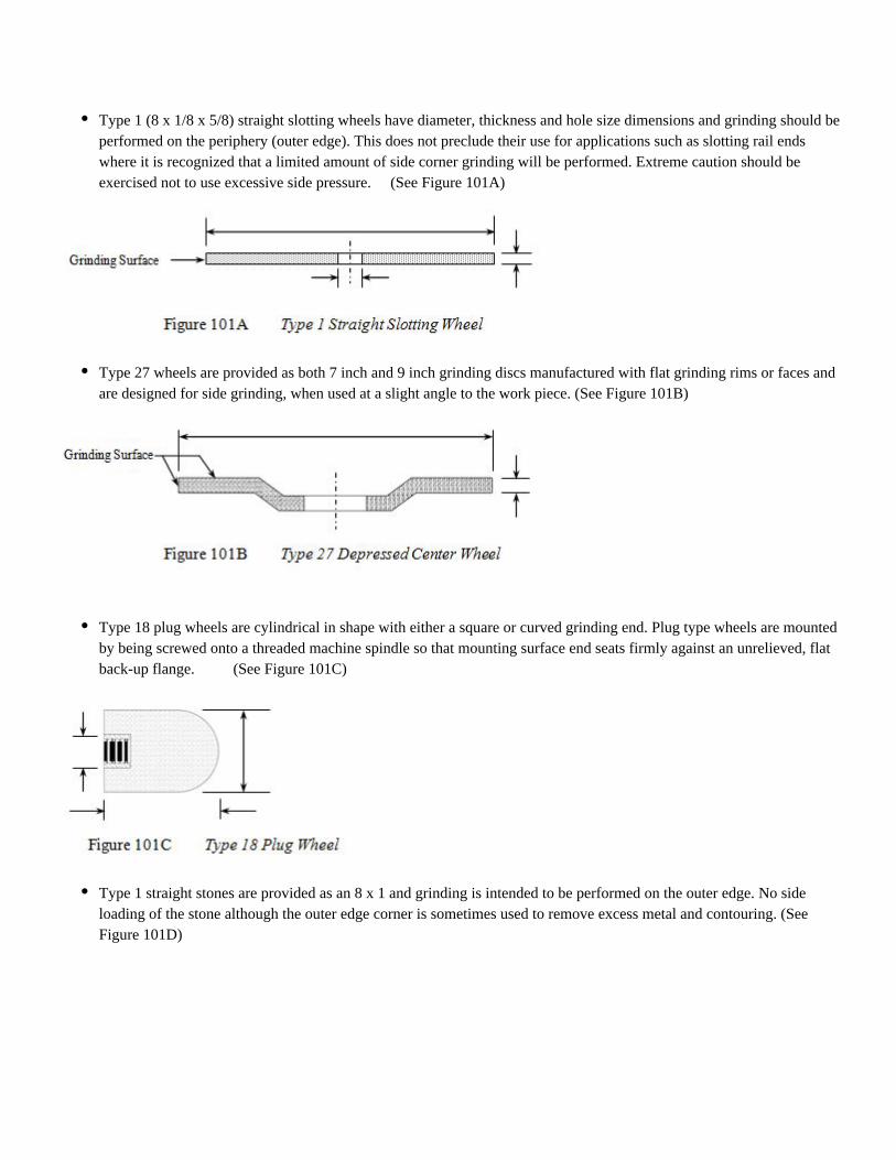
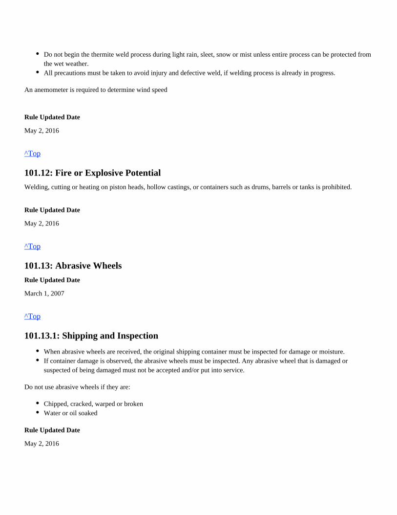
Type 1 (8 x 1/8 x 5/8) straight slotting wheels have diameter, thickness and hole size dimensions and grinding should beperformed on the periphery (outer edge). This does not preclude their use for applications such as slotting rail endswhere it is recognized that a limited amount of side corner grinding will be performed. Extreme caution should beexercised not to use excessive side pressure. (See Figure 101A)
Type 27 wheels are provided as both 7 inch and 9 inch grinding discs manufactured with flat grinding rims or faces andare designed for side grinding, when used at a slight angle to the work piece. (See Figure 101B)
Type 18 plug wheels are cylindrical in shape with either a square or curved grinding end. Plug type wheels are mountedby being screwed onto a threaded machine spindle so that mounting surface end seats firmly against an unrelieved, flatback-up flange. (See Figure 101C)
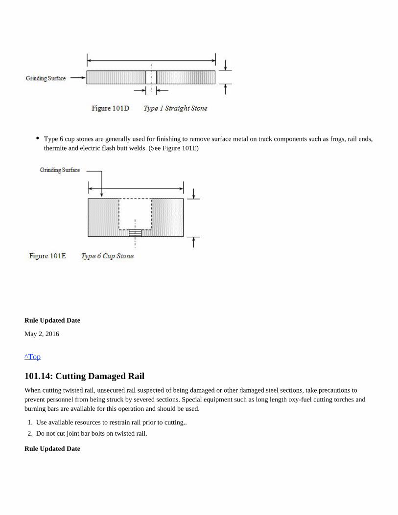
Type 1 straight stones are provided as an 8 x 1 and grinding is intended to be performed on the outer edge. No sideloading of the stone although the outer edge corner is sometimes used to remove excess metal and contouring. (SeeFigure 101D)
Rule Updated Date
May 2, 2016
^Top
101.14: Cutting Damaged Rail
When cutting twisted rail, unsecured rail suspected of being damaged or other damaged steel sections, take precautions toprevent personnel from being struck by severed sections. Special equipment such as long length oxy-fuel cutting torches andburning bars are available for this operation and should be used.
Rule Updated Date
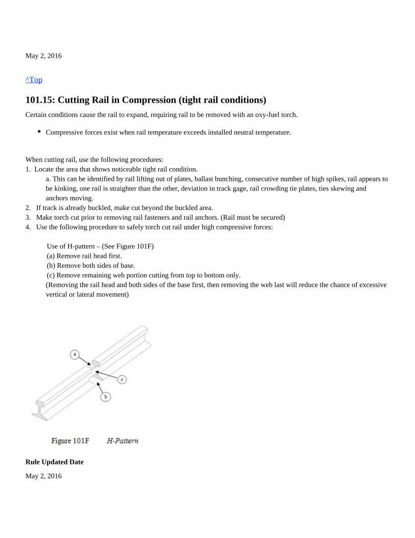
Type 6 cup stones are generally used for finishing to remove surface metal on track components such as frogs, rail ends,thermite and electric flash butt welds. (See Figure 101E)
1.
2.
Use available resources to restrain rail prior to cutting..
Do not cut joint bar bolts on twisted rail.
May 2, 2016
^Top
101.15: Cutting Rail in Compression (tight rail conditions)
Certain conditions cause the rail to expand, requiring rail to be removed with an oxy-fuel torch.
When cutting rail, use the following procedures:1. Locate the area that shows noticeable tight rail condition.
a. This can be identified by rail lifting out of plates, ballast bunching, consecutive number of high spikes, rail appears tobe kinking, one rail is straighter than the other, deviation in track gage, rail crowding tie plates, ties skewing andanchors moving.
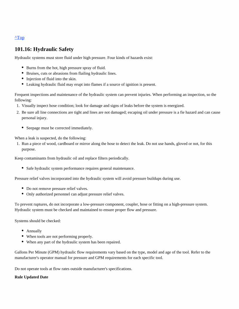
2. If track is already buckled, make cut beyond the buckled area.3. Make torch cut prior to removing rail fasteners and rail anchors. (Rail must be secured)4. Use the following procedure to safely torch cut rail under high compressive forces: Use of H-pattern – (See Figure 101F) (a) Remove rail head first. (b) Remove both sides of base. (c) Remove remaining web portion cutting from top to bottom only.
(Removing the rail head and both sides of the base first, then removing the web last will reduce the chance of excessivevertical or lateral movement)
Rule Updated Date
May 2, 2016
Compressive forces exist when rail temperature exceeds installed neutral temperature.
^Top
101.16: Hydraulic Safety
Hydraulic systems must store fluid under high pressure. Four kinds of hazards exist:
Frequent inspections and maintenance of the hydraulic system can prevent injuries. When performing an inspection, so thefollowing:
When a leak is suspected, do the following:
Keep contaminants from hydraulic oil and replace filters periodically.
Pressure relief valves incorporated into the hydraulic system will avoid pressure buildups during use.
To prevent ruptures, do not incorporate a low-pressure component, coupler, hose or fitting on a high-pressure system.Hydraulic system must be checked and maintained to ensure proper flow and pressure.
Systems should be checked:
Gallons Per Minute (GPM) hydraulic flow requirements vary based on the type, model and age of the tool. Refer to themanufacturer's operator manual for pressure and GPM requirements for each specific tool.
Do not operate tools at flow rates outside manufacturer's specifications.
Rule Updated Date
Burns from the hot, high pressure spray of fluid.Bruises, cuts or abrasions from flailing hydraulic lines.Injection of fluid into the skin.Leaking hydraulic fluid may erupt into flames if a source of ignition is present.
1.
2.
Visually inspect hose condition; look for damage and signs of leaks before the system is energized.
Be sure all line connections are tight and lines are not damaged; escaping oil under pressure is a fie hazard and can causepersonal injury.
Seepage must be corrected immediately.
1. Run a piece of wood, cardboard or mirror along the hose to detect the leak. Do not use hands, gloved or not, for thispurpose.
Safe hydraulic system performance requires general maintenance.
Do not remove pressure relief valves.Only authorized personnel can adjust pressure relief valves.
AnnuallyWhen tools are not performing properly.When any part of the hydraulic system has been repaired.
May 2, 2016
^Top
101.17: Equipment Safety
Portable power tools, machinery and equipment must not be operated without the required safety guards. All belts, shafts, gearsand other moving parts on machinery must be fully enclosed and guarded.
Maintain equipment in proper working condition and follow all maintenance requirements for that specific equipment.
Rule Updated Date
March 1, 2007
^Top
Union Pacific Rules Track Welding Rules and Procedures
102.0: ELECTRIC WELDING
102.1: Welding and Cutting Processes
Rule Updated Date
March 1, 2007
102.1: Welding and Cutting Processes102.1.1: Shielded Metal Arc Welding (SMAW)102.1.2: Flux Core Arc Welding (FCAW)102.1.3: Flash Welding (FW)102.1.4: Carbon Arc Cutting (CAC)102.2: Welding Current - Measurement102.2.1: Currents102.2.2: Types of Welding Power102.2.3: Duty Cycle102.3: Electrodes / Electrode Holder102.3.1: Approved Products102.4: Electric Welding Equipment102.4.1: Power Source Setup102.4.2: Wire Feed Equipment102.4.3: Electric Welding Eequipment Inspection102.4.4: Qualified Mechanic or Electrician102.4.5: Polarity and Range Finder Switches102.4.6: Cable Insulation and Connectors102.4.7: Cable Repairs102.4.8: Protect from Electrical Shock and Moisture102.4.9: Unwind Cables102.5: Ground Connection102.5.1: Ground Connection Precautions102.5.2: Ground Cable Clamp102.5.3: Jump Starting102.5.4: Location and Inspection of Welding Cables
^Top
102.1.1: Shielded Metal Arc Welding (SMAW)
Shielded Metal Arc Welding is frequently referred to as stick or covered electrode welding. Stick welding is among the mostwidely used welding processes.
The flux covering the electrode melts during welding. This forms the gas and slag to shield the arc and molten weld pool. Theslag must be chipped off the weld bead after welding. The flux also provides a method of adding deoxidizers, and alloyingelements to the weld metal.
Rule Updated Date
March 1, 2007
^Top
102.1.2: Flux Core Arc Welding (FCAW)
Flux Core Arc Welding is frequently referred to as wire welding. FCAW welding is a commonly used high deposition ratewelding process. The filler wires that are used in FCAW are tubular, and the core is filled with a mixture of mineral flux andpowder. This is a self-shielding process that is also called "Innershield". Shielding gases are formed from the inner flux as thewelding metal is deposited and like the SMAW process, is used to shield the arc and molten weld pool. Wire is continuouslyfed from a spool. FCAW welding is therefore referred to as a semiautomatic welding process.
Rule Updated Date
March 1, 2007
^Top
102.1.3: Flash Welding (FW)
(Electric Flash-Butt Welding)
A resistance welding process that produces a weld at the rail end surfaces of a butt joint by a flashing action and by theapplication of pressure after heating is substantially completed.
Rule Updated Date
March 1, 2007
^Top
102.1.4: Carbon Arc Cutting (CAC)
Thermal cutting using an arc for melting the metal, and a stream of air to remove the molten metal. This process is used toremove defective metal from manganese track components.
Rule Updated Date
March 1, 2007
^Top
102.2: Welding Current - Measurement
Rule Updated Date
March 1, 2007
^Top
102.2.1: Currents
The three different types of current used for welding are;
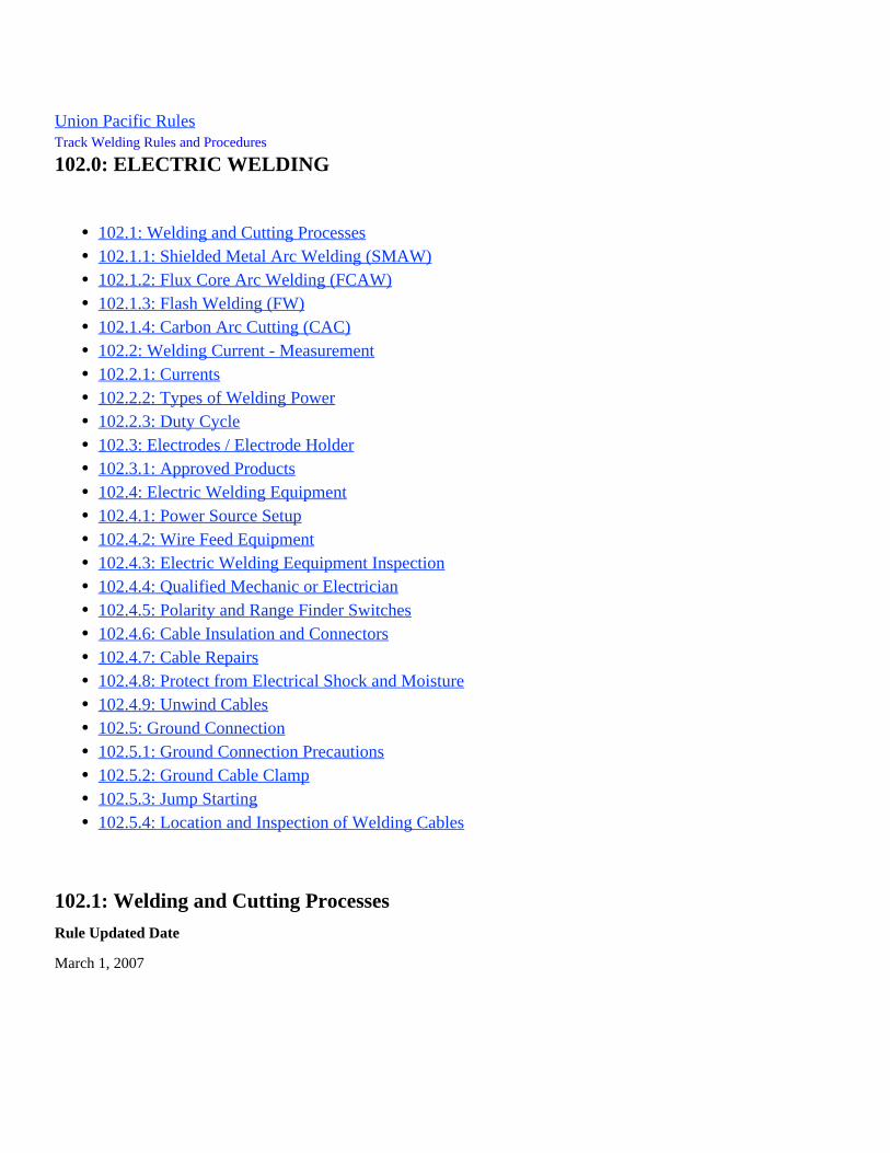
In Direct Current Electrode Negative, the electrode is negative and the work is positive. Electricity flows from the electrode tothe work piece producing a high electrode-melting rate and increasing penetration. (See Figure 102A)
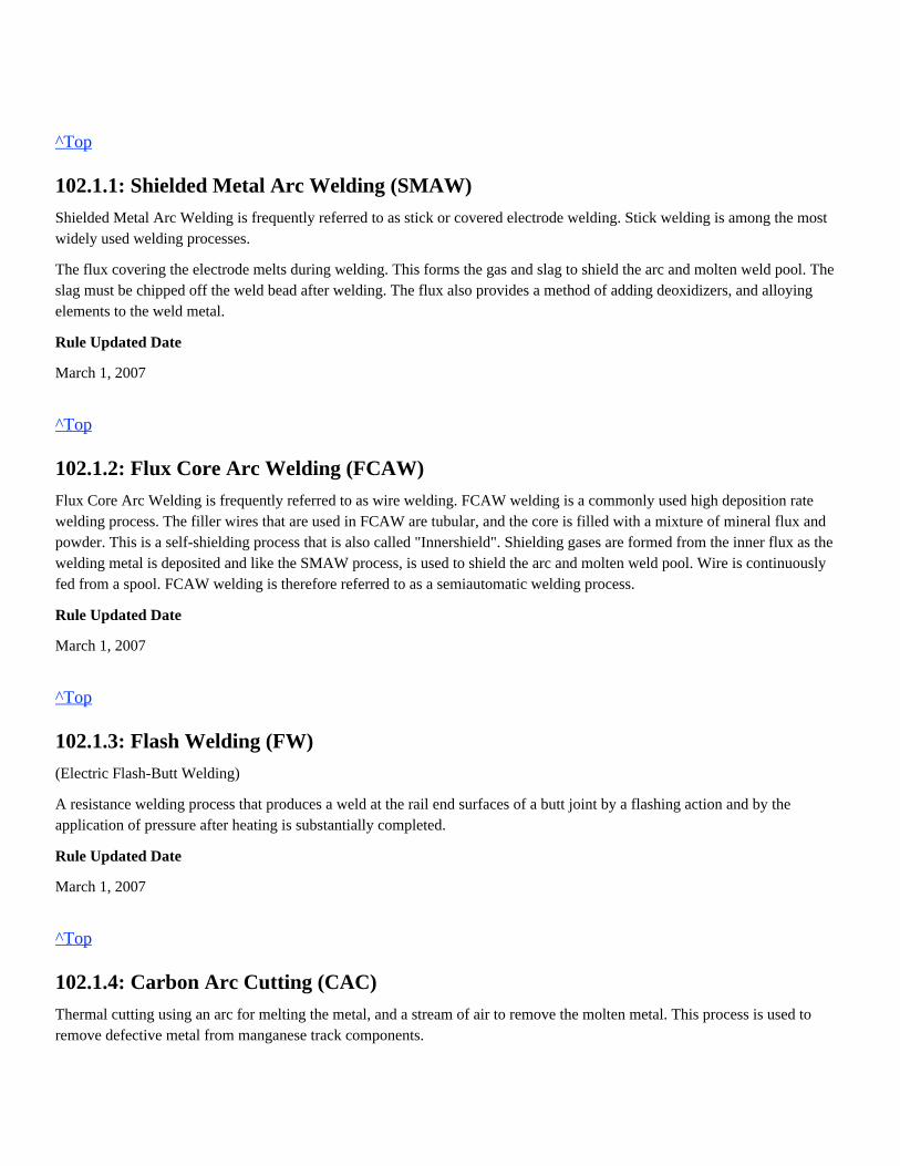
In Direct Current Electrode Positive, the electrode is positive and the work is negative. Electricity flows from the work piece to
Voltage (volts) is the measurement of electrical pressure, in the same way that pounds per square inch is a measurementof water pressure. Voltage controls the maximum gap the electrons can jump to form the arc. A higher voltage can jumpa larger gap.Amperage (amps) is the measurement of the total number of electrons flowing, in the same way that gallons is ameasurement of the amount or volume of water flowing. Amperage controls the size of the arc.
Alternating Current (AC).Direct Current Electrode Negative (DCEN) also known as Direct Current Straight Polarity (DCSP).Direct Current Electrode Positive (DCEP) also known as Direct Current Reverse Polarity (DCRP).
the electrode producing less heat in the work piece and providing the best welding arc characteristics. (See Figure 102B)
Rule Updated Date
May 2, 2016
^Top
102.2.2: Types of Welding Power
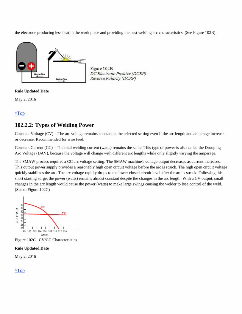
Constant Voltage (CV) – The arc voltage remains constant at the selected setting even if the arc length and amperage increaseor decrease. Recommended for wire feed.
Constant Current (CC) – The total welding current (watts) remains the same. This type of power is also called the DroopingArc Voltage (DAV), because the voltage will change with different arc lengths while only slightly varying the amperage.
The SMAW process requires a CC arc voltage setting. The SMAW machine's voltage output decreases as current increases.This output power supply provides a reasonably high open circuit voltage before the arc is struck. The high open circuit voltagequickly stabilizes the arc. The arc voltage rapidly drops to the lower closed circuit level after the arc is struck. Following thisshort starting surge, the power (watts) remains almost constant despite the changes in the arc length. With a CV output, smallchanges in the arc length would cause the power (watts) to make large swings causing the welder to lose control of the weld.(See to Figure 102C)
Figure 102C CV/CC Characteristics
Rule Updated Date
May 2, 2016
^Top
102.2.3: Duty Cycle
The Duty Cycle is the percentage of time a welding machine can be used continuously at its maximum setting based on 10minutes. A 60% duty cycle means that out of every 10 minutes, the machine can be used for 6 minutes at the maximum ratedcurrent. When providing power at this level, it must be cooled off for 4 minutes out of every ten minutes or equipment damagemay result.
Rule Updated Date
March 1, 2007
^Top
102.3: Electrodes / Electrode Holder
Rule Updated Date
March 1, 2007
^Top
102.3.1: Approved Products
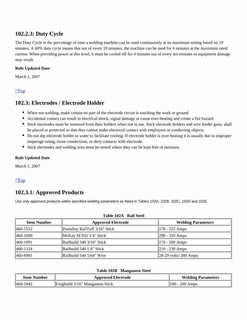
Use only approved products within specified welding parameters as listed in Tables 102A, 102B, 102C, 102D and 102E.
Table 102A Rail Steel
Item Number Approved Electrode Welding Parameters
460-1512 Postalloy RailTuff 3/16" Stick 170 - 225 Amps
460-1690 McKay M-932 1/4" Stick 290 - 310 Amps
460-1091 Railbuild 540 3/16" Stick 170 - 200 Amps
460-1124 Railbuild 540 1/4" Stick 210 - 230 Amps
460-6901 Railbuild 540 5/64" Wire 28-29 volts/ 280 Amps
Table 102B Manganese Steel
Item Number Approved Electrode Welding Parameters
460-1042 Frogbuild 3/16" Manganese Stick 180 - 200 Amps
When not welding, make certain no part of the electrode circuit is touching the work or ground.Accidental contact can result in electrical shock, signal damage or cause over-heating and create a fire hazard.Stick electrodes must be removed from their holders when not in use. Stick electrode holders and wire feeder guns, shallbe placed or protected so that they cannot make electrical contact with employees or conducting objects.Do not dip electrode holder in water to facilitate cooling. If electrode holder is over-heating it is usually due to improperamperage rating, loose connections, or dirty contacts with electrode.Stick electrodes and welding wire must be stored where they can be kept free of moisture.
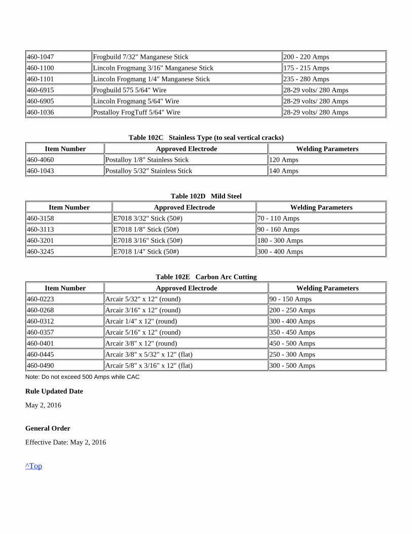
460-1047 Frogbuild 7/32" Manganese Stick 200 - 220 Amps
460-1100 Lincoln Frogmang 3/16" Manganese Stick 175 - 215 Amps
460-1101 Lincoln Frogmang 1/4" Manganese Stick 235 - 280 Amps
460-6915 Frogbuild 575 5/64" Wire 28-29 volts/ 280 Amps
460-6905 Lincoln Frogmang 5/64" Wire 28-29 volts/ 280 Amps
460-1036 Postalloy FrogTuff 5/64" Wire 28-29 volts/ 280 Amps
Table 102C Stainless Type (to seal vertical cracks)
Item Number Approved Electrode Welding Parameters
460-4060 Postalloy 1/8" Stainless Stick 120 Amps
460-1043 Postalloy 5/32" Stainless Stick 140 Amps
Table 102D Mild Steel
Item Number Approved Electrode Welding Parameters
460-3158 E7018 3/32" Stick (50#) 70 - 110 Amps
460-3113 E7018 1/8" Stick (50#) 90 - 160 Amps
460-3201 E7018 3/16" Stick (50#) 180 - 300 Amps
460-3245 E7018 1/4" Stick (50#) 300 - 400 Amps
Table 102E Carbon Arc Cutting
Item Number Approved Electrode Welding Parameters
460-0223 Arcair 5/32" x 12" (round) 90 - 150 Amps
460-0268 Arcair 3/16" x 12" (round) 200 - 250 Amps
460-0312 Arcair 1/4" x 12" (round) 300 - 400 Amps
460-0357 Arcair 5/16" x 12" (round) 350 - 450 Amps
460-0401 Arcair 3/8" x 12" (round) 450 - 500 Amps
460-0445 Arcair 3/8" x 5/32" x 12" (flat) 250 - 300 Amps
460-0490 Arcair 5/8" x 3/16" x 12" (flat) 300 - 500 Amps
Note: Do not exceed 500 Amps while CAC
Rule Updated Date
May 2, 2016
General Order
Effective Date: May 2, 2016
^Top
102.4: Electric Welding Equipment
Rule Updated Date
March 1, 2007
^Top
102.4.1: Power Source Setup
On power source equipment that has a run/idle switch, switch must be placed on "run" when welding.
Equipment reference tables are intended to help the equipment operator in determining the proper setting when using stickelectrodes and are estimates only. Power source meters should be checked periodically to ensure accurate readings. (Refer toappendices 1-8)
Rule Updated Date
May 2, 2016
^Top
102.4.2: Wire Feed Equipment
Wire feed welding equipment is an efficient and recommended process to repair track components.
The wire size standard on the Union Pacific Railroad is 5/64 inch and it is important to ensure that the correct drive rolls arebeing used.
Wire spool must be removed after each use, placing the spool back in the plastic bag and then in the box. This not onlyprotects the wire, spool and equipment from damage but it is also reduces the weight of the feeder when loading or unloadingfrom the truck.
To mount the spool and make connections:
When using wire feed equipment to repair track components, equipment must be used on the CV (Constant Voltage)setting if power source is capable.Power source condition and age impact amperage and voltage, and must be taken into consideration during setup.
A new wire spool weighs 30 pounds. Together, the feeder and spool weigh approximately 65 pounds.
1.
2.
3.
4.
5.
Remove retaining ring and align the small hub pin with corresponding hole on the spool.
Clip any kinks from the wire and mount the spool onto the hub.
Open the pressure assembly by flipping up the adjustment knob and carefully thread the wire through the wire guides untiltwo or three inches of wire protrudes from the machine.
Flip down adjustment knob and secure the spool with retaining ring.
Wire installation is made easier by laying out the gun in as straight a line as possible.
When welding, always clip 1-inch of the wire before depositing the next weld bead.
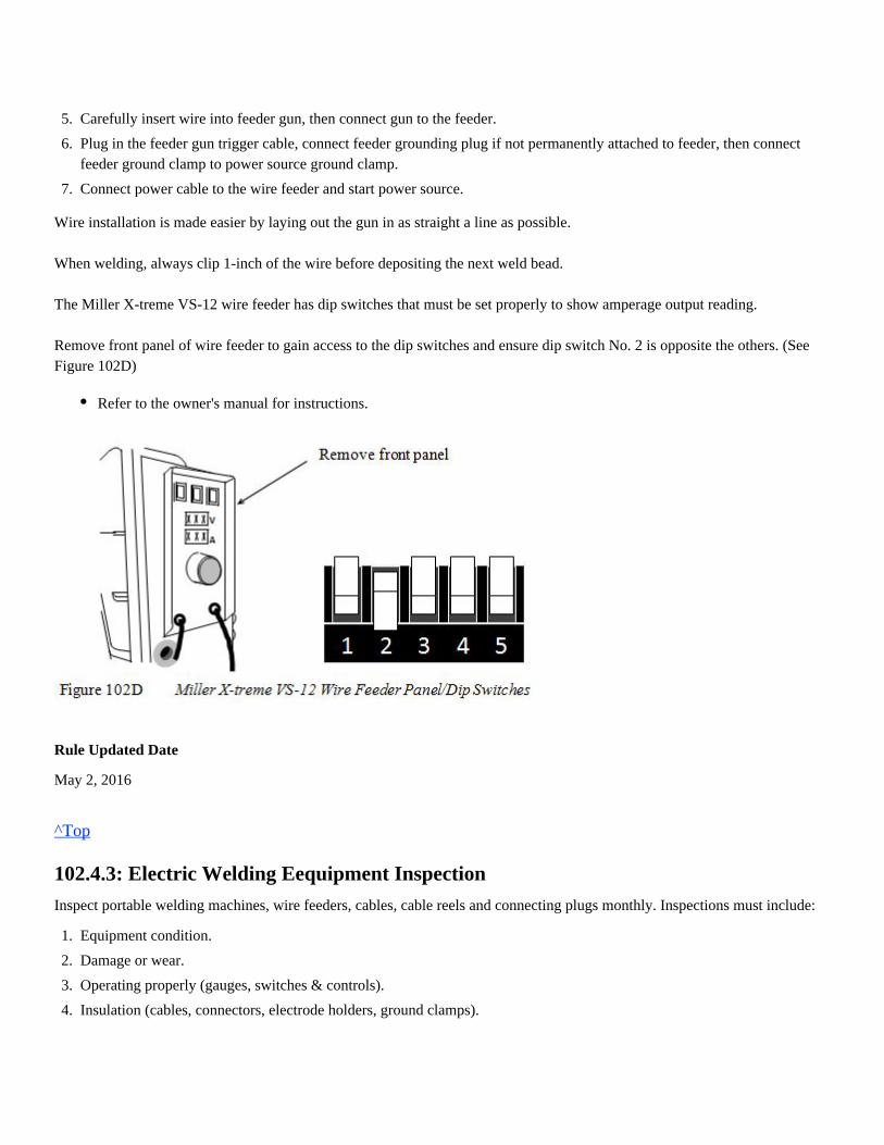
The Miller X-treme VS-12 wire feeder has dip switches that must be set properly to show amperage output reading.
Remove front panel of wire feeder to gain access to the dip switches and ensure dip switch No. 2 is opposite the others. (SeeFigure 102D)
Rule Updated Date
May 2, 2016
^Top
102.4.3: Electric Welding Eequipment Inspection
Inspect portable welding machines, wire feeders, cables, cable reels and connecting plugs monthly. Inspections must include:
5.
6.
7.
Carefully insert wire into feeder gun, then connect gun to the feeder.
Plug in the feeder gun trigger cable, connect feeder grounding plug if not permanently attached to feeder, then connectfeeder ground clamp to power source ground clamp.
Connect power cable to the wire feeder and start power source.
Refer to the owner's manual for instructions.
1.
2.
3.
4.
Equipment condition.
Damage or wear.
Operating properly (gauges, switches & controls).
Insulation (cables, connectors, electrode holders, ground clamps).
Use the appropriate form 24248 to record the inspection information, including the inspection date, gang#, if defect is found,employee signature, corrective action (if applicable) for later review by a welding supervisor.
Completed forms must be sent to the track welding manager.
Form 24248 can be accessed on the UP web under the HR Craft Training page ordered through the online requisition system
Rule Updated Date
May 2, 2016
^Top
102.4.4: Qualified Mechanic or Electrician
Only a qualified mechanic or electrician is permitted to make repairs or internal adjustments to electric welding equipment.
Exception: Welders may make routine operating adjustments. Refer to owner's manual for scheduled maintenance.
Rule Updated Date
May 2, 2016
^Top
102.4.5: Polarity and Range Finder Switches
To avoid arcing and damage, do not change settings on the amperage range selector switch or polarity output selectorswitch while machine is operating under welding current load.
Rule Updated Date
May 2, 2016
^Top
102.4.6: Cable Insulation and Connectors
Electrode and ground cables must be insulated throughout their entire length. Use 3/0 approved cable and approved cableconnections with insulated covering. (Sustained overloading will cause cable failure and result in possible electrical shock orfire hazard)
Rule Updated Date
May 2, 2016
^Top
102.4.7: Cable Repairs
If cables or cable ends must be repaired, turn off power and use lockout/tagout procedures. Disconnect the cable at the firstjoint and coil the cable to prevent it from being reconnected while under repair.
Rule Updated Date
May 2, 2016
^Top
102.4.8: Protect from Electrical Shock and Moisture
Protect yourself from possible dangerous electrical shock. The electrode and work (or ground) circuits are electrically "HOT"when the welder is on.
Rule Updated Date
May 2, 2016
^Top
102.4.9: Unwind Cables
Unwind entire length of cables from the reels when welding.
Rule Updated Date
May 2, 2016
Always use same size cable when making connections.Always use approved insulated welding cable connectors to make all connections. The capacity of the connector mustbe at least equivalent to that of the cable.Cables cannot be damaged or repaired within 10 feet of the electrode holder or ground clamp
Do not permit contact between "HOT" parts of the circuits and bare skin or wet clothing.Wear leather welding gloves that are dry and free of holes.Insulate yourself from the work and ground by using dry insulation when wet conditions are present.Maintain the electrode holder, work clamp, welding cable and welding machine in good, safe operating condition.When using the welding machine as a power source for mechanized welding, the above precautions also apply for thewelding wire, wire reel, welding head or nozzle.Do not loop or coil electrode cables around the body.During inclement weather, electrical welding equipment must be properly protected from moisture.
Failure to do so creates heat buildup resulting in damage to welding cables and equipment.High welding currents in coiled cables will create a magnetic field that reduces the welding output.
^Top
102.5: Ground Connection
When performing electric arc welding on rail, crossing pads, gage plates or other track components, apply the ground clamp tothat particular part being welded.
Rule Updated Date
May 2, 2016
^Top
102.5.1: Ground Connection Precautions
Rule Updated Date
March 1, 2007
^Top
102.5.2: Ground Cable Clamp
Ensure ground cable clamp provides good mechanical and electrical contacts by grinding the contact area to a shiny surface.A poor ground connection will cause excessive heat buildup, which can damage welding cables and equipment, create an arcbetweenthe ground clamp and attached metal resulting in cracks, or cause burns.Do not handle ground clamp or electrode holder with bare hands.
Rule Updated Date
May 2, 2016
^Top
102.5.3: Jump Starting
Do not jump start vehicles or equipment directly from welding machine.
Do not permanently bond the welding ground lead to any rail, steel building or other structure.Fixed electrical welding equipment must be permanently grounded on the service side to the ground system.
Jump starting vehicles or equipment is allowed only if power source is equipped with a jump-start kit.
Rule Updated Date
March 1, 2007
^Top
102.5.4: Location and Inspection of Welding Cables
Do not lay cables over rails.When welding on individual track components or switch components, e.g., insulated switch plates, turnout frogs, rail ends,switch points etc., place welding cables under the rail.Ensure grounding clamp is placed on the same component to be welded on.
When laying cables under the rail, ensure cables are not contacting the rail base or any other area of the rail.
Inspect welding cables prior to each use.
Rule Updated Date
May 2, 2016
^Top
Never place ground clamp across an insulated joint or track device separated by insulation such as insulated gage plates.
If necessary clear out sufficient ballast under the rail to increase clearance.Contact between the welding cable and rail may shunt the track and cause excessive current to travel through the rail tothe signal cabinets and houses, and could lead to damaged signal components.Use a thick non-conductive material, such as a rubber mat placed between the rail base and welding cables to preventelectrical arcing and limit the influence of current leakage.
Only cables in proper working condition may be used.Inspect welding cables for hardened, cracked, split, cut or missing insulation which may allow current leakage. Do notuse cables if any of these conditions are present.
Union Pacific Rules Track Welding Rules and Procedures
103.0: OXY-FUEL EQUIPMENT
Chapter Introduction
Employees must read and understand all rules associated with the proper setup, use and storage of oxy-fule equipment. Rules in thischapter, if applicable, apply to both oxy-fule and fule-gas operations.
103.1: Personal Protective Equipment (PPE)103.2: Authorized to Use Oxy-fuel Equipment103.3: General Instructions103.3.1: Repairs or Alterations103.3.2: Equipment Condition103.3.3: Ventilation103.3.4: Fire or Exposive Potential103.4: Welding Gas Description103.4.1: Oxygen103.4.2: Liquid Oxygen103.4.3: Acetylene103.4.4: Propane103.5: Cylinders103.5.1: Cylinder Construction - Oxygen (See Figure 103B)103.5.2: Cylinder Construction - Liquid Oxygen (See Figure 103C)103.5.3: Cylinder Construction - Acetylene (See Figure 103D)103.5.4: Exposure to Excessive Heat103.5.5: Storing Cylinders103.5.6: Working With Cylinders103.5.7: Transporting Cylinders103.5.8: Empty Cylinders103.5.9: Leaking Cylinder103.5.10: Changing Cylinders103.6: Hot Metal Precautions103.7: Regulators103.7.1: Proper Regulator103.7.2: Single/Two Stage Regulators103.7.3: Connections and Adaptors103.7.4: Connecting Regulators103.7.5: Protecting Regulators103.8: Cylinder Valves
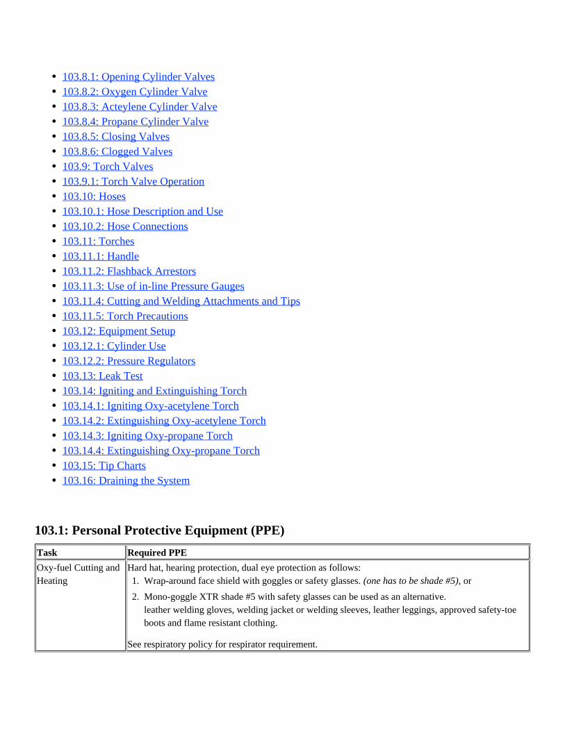
103.1: Personal Protective Equipment (PPE)
Task Required PPE
Oxy-fuel Cutting andHeating
Hard hat, hearing protection, dual eye protection as follows:
See respiratory policy for respirator requirement.
103.8.1: Opening Cylinder Valves103.8.2: Oxygen Cylinder Valve103.8.3: Acteylene Cylinder Valve103.8.4: Propane Cylinder Valve103.8.5: Closing Valves103.8.6: Clogged Valves103.9: Torch Valves103.9.1: Torch Valve Operation103.10: Hoses103.10.1: Hose Description and Use103.10.2: Hose Connections103.11: Torches103.11.1: Handle103.11.2: Flashback Arrestors103.11.3: Use of in-line Pressure Gauges103.11.4: Cutting and Welding Attachments and Tips103.11.5: Torch Precautions103.12: Equipment Setup103.12.1: Cylinder Use103.12.2: Pressure Regulators103.13: Leak Test103.14: Igniting and Extinguishing Torch103.14.1: Igniting Oxy-acetylene Torch103.14.2: Extinguishing Oxy-acetylene Torch103.14.3: Igniting Oxy-propane Torch103.14.4: Extinguishing Oxy-propane Torch103.15: Tip Charts103.16: Draining the System
1.
2.
Wrap-around face shield with goggles or safety glasses. or(one has to be shade #5),
Mono-goggle XTR shade #5 with safety glasses can be used as an alternative.leather welding gloves, welding jacket or welding sleeves, leather leggings, approved safety-toeboots and flame resistant clothing.
Rule Updated Date
May 2, 2016
^Top
103.2: Authorized to Use Oxy-fuel Equipment
Only authorized employees are permitted to use oxy-fuel equipment. Welding, cutting and heating will be done only by orunder the direct supervision of a qualified employee and comply with manufacturer's instructions.
Qualification:To be initially qualified to use oxy-fuel equipment, employees must:1. Be properly trained in the use of such equipment, completion of an exam and skills assessment performed by a Manager ofTrack Welding, Welding Supervisor or Welding Instructor.
Employees must re-qualify every three (3) years via Computer Based Training (CBT) and demonstrate their skills with thewelding management employee.
Rule Updated Date
May 2, 2016
^Top
103.3: General Instructions
Rule Updated Date
May 2, 2016
^Top
103.3.1: Repairs or Alterations
Do not make repairs or alterations to cylinders, valves or torches. Defective regulators, gauges, torches or other equipmentmust not be used and must be returned to designated point for repair. Hoses showing indication of leaks, burns, worn places, orevidence of damage from flashback or other defects must be repaired or replaced.
Hose repair can be made in the field with the approved crimping ferrules but no more than 2 splices are allowed for anylength of hose.Use of tape, wire or hose clamps to repair hose is prohibited.Splices must be removed prior to initial use on the next day or shift, or hose must be replaced.If hose is damaged beyond repair, it must be replaced.
Rule Updated Date
May 2, 2016
^Top
103.3.2: Equipment Condition
Inspect all equipment before use and verify it is free of defects and in proper working condition.
Rule Updated Date
May 2, 2016
^Top
103.3.3: Ventilation
Work in well ventilated areas. Exposure to lead, zinc or other welding fumes requires use of an approved respirator. Spray ordust respirators are not suitable and must not be used.
Rule Updated Date
May 2, 2016
^Top
103.3.4: Fire or Exposive Potential
Welding, cutting or heating on piston heads, hollow casting, or containers such as drums, barrels, or tanks is prohibited.
Rule Updated Date
May 2, 2016
^Top
103.4: Welding Gas Description
Rule Updated Date
May 2, 2016
^Top
103.4.1: Oxygen
A. Oxygen is a colorless, tasteless, odorless gas that is slightly heavier than air.B. It is non-flammable but will support combustion with other elements.C. The presence of pure oxygen will drastically increase the speed and force with which burning takes place.D. Oxygen is required to support any burning process. It is combined with a "fuel" gas to produce the desired operating flame.E. Always refer to oxygen as "oxygen", never as "air". Combustibles should be kept away from oxygen, including the cylinder,valves, regulators, and other hose apparatus. Oxygen should never be used in any air tools.F. Oxygen must not be used for compressed air, as a source of pressure or to "dust" clothing.G. Do not allow oil or grease to come in contact with oxygen.H. Oil or grease in the presence of oxygen may spontaneously ignite and burn violently or explode.I. Oxygen cylinders and apparatus should not be handled with oily hands or oily gloves.J. Do not allow oil or grease to touch regulators, valves or connections.
Rule Updated Date
May 2, 2016
^Top
103.4.2: Liquid Oxygen
A. Liquid oxygen is pale blue and extremely cold. Although non-flammable, oxygen is a strong oxidizer.B. Liquid oxygen is a cryogenic liquid. Cryogenic liquids are liquefied gases that have a normal boiling point below -238°F(-150°C). Liquid oxygen has a boiling point of -297.3°F (-183.0°C).C. Because the temperature difference between the product and the surrounding environment is substantial—even in thewinter—keeping liquid oxygen insulated from the surrounding heat is essential. The product also requires special equipmentfor handling and storage.D. Oxygen is often stored as a liquid, although it is used primarily as a gas.
Rule Updated Date
May 2, 2016
^Top
103.4.3: Acetylene
A. Acetylene is a colorless, flammable gas composed of carbon and hydrogen, manufactured by the reaction of water andcalcium carbide.B. Acetylene, when used with oxygen, produces the highest flame temperature of any of the fuel-gases, approximately 6,300ºF.C. Because acetylene is stored as a liquid, the cylinder will only work properly if the tank is used in the upright position.D. Using or storing the tank in any other position can be extremely dangerous.E. Although acetylene is stable under low pressure, if compressed above 15 psi it becomes unstable.F. Avoid exposing filled cylinders to heat, furnaces, radiators, open fires, or sparks (from a torch).G. Avoid striking the cylinder against other objects and creating sparks.H. To avoid shock when transporting cylinders, do not drag, roll, or slide them on their sides.I. Acetylene must not be drawn off in volumes greater than 1/7 of the cylinder's rated capacity.
J. If higher volumes are needed, use a manifold system of sufficient size.
Rule Updated Date
May 2, 2016
^Top
103.4.4: Propane
A. Propane is a hydrocarbon (C H ) and is sometimes referred to as liquefied petroleum gas, LP-gas or LPG. It is nontoxic,3 8
colorless and virtually odorless and heavier than air.B. Propane is produced from both natural gas processing and crude oil refining, in roughly equal amounts.C. As with natural gas, a strong identifying odor is added so the gas can be readily detected.D. If liquid propane leaks, it vaporizes and dissipates into the air.
Rule Updated Date
May 2, 2016
^Top
103.5: Cylinders
A sticker located near the top of the cylinder identifies the cylinder's contents.(See Figure 103A)
Rule Updated Date
May 2, 2016
^Top
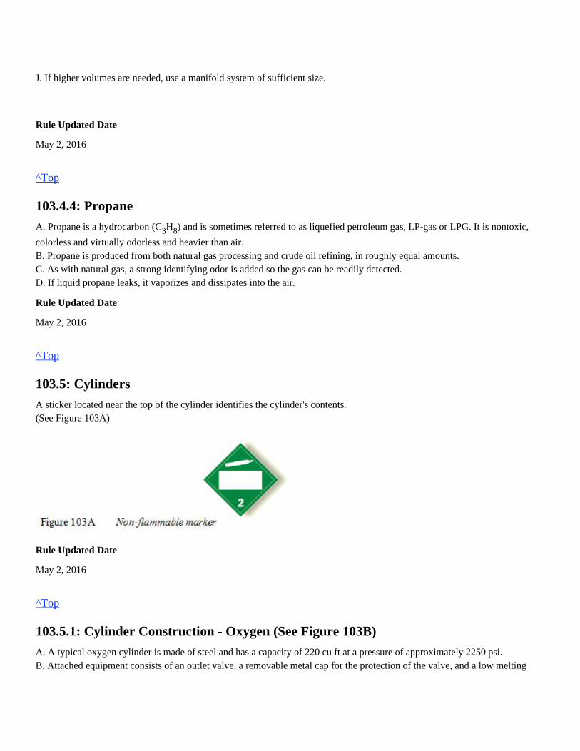
103.5.1: Cylinder Construction - Oxygen (See Figure 103B)
A. A typical oxygen cylinder is made of steel and has a capacity of 220 cu ft at a pressure of approximately 2250 psi.B. Attached equipment consists of an outlet valve, a removable metal cap for the protection of the valve, and a low melting
point safety fuse plug and disk.C. The cylinder is fabricated from a single plate of high-grade steel with no seams and is heat-treated for maximum strength.D. Because of their high pressure, oxygen cylinders undergo extensive testing prior to their release for work, and must beperiodically re-tested thereafter.
Rule Updated Date
May 2, 2016
^Top
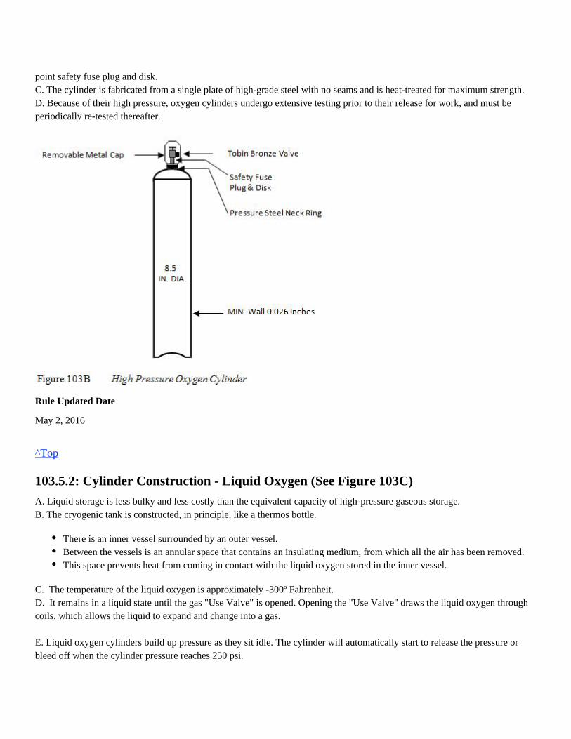
103.5.2: Cylinder Construction - Liquid Oxygen (See Figure 103C)
A. Liquid storage is less bulky and less costly than the equivalent capacity of high-pressure gaseous storage.B. The cryogenic tank is constructed, in principle, like a thermos bottle.
C. The temperature of the liquid oxygen is approximately -300º Fahrenheit.D. It remains in a liquid state until the gas "Use Valve" is opened. Opening the "Use Valve" draws the liquid oxygen throughcoils, which allows the liquid to expand and change into a gas.
E. Liquid oxygen cylinders build up pressure as they sit idle. The cylinder will automatically start to release the pressure orbleed off when the cylinder pressure reaches 250 psi.
There is an inner vessel surrounded by an outer vessel.Between the vessels is an annular space that contains an insulating medium, from which all the air has been removed.This space prevents heat from coming in contact with the liquid oxygen stored in the inner vessel.
F. Cylinders with the highest psi regulator reading should be used first.G. Care must be taken not to drop liquid oxygen cylinders.H. Liquid oxygen cylinders must remain upright or in a vertical position.I. In the event a liquid oxygen cylinder is dropped, tipped over, or abused, do the following:
J. Prior to applying the oxygen regulator to the liquid oxygen cylinder, slightly open the "Use' valve to clear the valve stemand then close. Position the oxygen regulator on the "Use" valve and tighten.
Note: Since the "Use" valve stem is fairly long, it must be supported with a gloved hand.
K. The "Use" valve may then be opened slowly for use.L. Never open the "Liquid" valve.
Rule Updated Date
May 2, 2016
^Top
103.5.3: Cylinder Construction - Acetylene (See Figure 103D)
A. To decrease the size of the open spaces in the cylinder, acetylene cylinders are filled with porous materials such as balsawood, charcoal, corn pith, or portland cement.B. Acetone, a colorless flammable liquid, is added to the cylinder until about 40 percent of the porous material is saturated.
Slowly raise the cylinder to a vertical position.Open the vent to release any excess pressure and leave the valve in the open position.Remove the liquid product from the vessel as soon as possible.Inspect the cylinder before returning it to service.
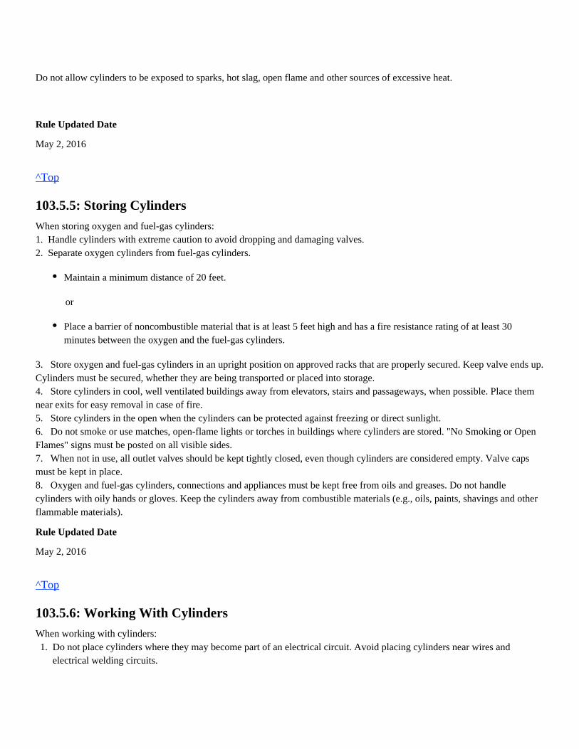
The porous material acts as a large sponge, which absorbs the acetone, which then absorbs the acetylene.In this process, the volume of acetone increases as it absorbs the acetylene, while acetylene, being a gas, decreases involume.Fuel-gas cylinders are identified with a flammable sticker attached near the top of the cylinder.
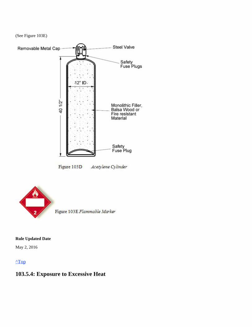
(See Figure 103E)
Rule Updated Date
May 2, 2016
^Top
103.5.4: Exposure to Excessive Heat
Do not allow cylinders to be exposed to sparks, hot slag, open flame and other sources of excessive heat.
Rule Updated Date
May 2, 2016
^Top
103.5.5: Storing Cylinders
When storing oxygen and fuel-gas cylinders:1. Handle cylinders with extreme caution to avoid dropping and damaging valves.2. Separate oxygen cylinders from fuel-gas cylinders.
or
3. Store oxygen and fuel-gas cylinders in an upright position on approved racks that are properly secured. Keep valve ends up.Cylinders must be secured, whether they are being transported or placed into storage.4. Store cylinders in cool, well ventilated buildings away from elevators, stairs and passageways, when possible. Place themnear exits for easy removal in case of fire.5. Store cylinders in the open when the cylinders can be protected against freezing or direct sunlight.6. Do not smoke or use matches, open-flame lights or torches in buildings where cylinders are stored. "No Smoking or OpenFlames" signs must be posted on all visible sides.7. When not in use, all outlet valves should be kept tightly closed, even though cylinders are considered empty. Valve capsmust be kept in place.8. Oxygen and fuel-gas cylinders, connections and appliances must be kept free from oils and greases. Do not handlecylinders with oily hands or gloves. Keep the cylinders away from combustible materials (e.g., oils, paints, shavings and otherflammable materials).
Rule Updated Date
May 2, 2016
^Top
103.5.6: Working With Cylinders
When working with cylinders:
Maintain a minimum distance of 20 feet.
Place a barrier of noncombustible material that is at least 5 feet high and has a fire resistance rating of at least 30minutes between the oxygen and the fuel-gas cylinders.
1.
2.
Do not place cylinders where they may become part of an electrical circuit. Avoid placing cylinders near wires andelectrical welding circuits.
Cylinders may be lifted by a crane, derrick or hoist when a company-approved lifting device is used, andonly (sling)employees have been instructed on its use.Note: Use of an electric magnet to lift cylinders is prohibited.
Rule Updated Date
May 2, 2016
^Top
103.5.7: Transporting Cylinders
When transporting gas cylinders;
1. Remove regulators and apply standard caps before transporting oxygen or fuel- gas cylinders, unless valves are covered by aDepartment of Transportation (DOT) approved safety cap or device designed for that purpose.
2. Caps need not be applied to complete a single series of welding operations while on company property.
3. When transporting oxygen and fuel-gas cylinders in tool cars or enclosed compartments, ensure proper ventilation isprovided.
Rule Updated Date
May 2, 2016
^Top
103.5.8: Empty Cylinders
When cylinders are empty;
2.
3.
4.
5.
6.
7.
Do not strike an arc on or tap an electrode against a cylinder.
Oxygen and fuel-gas cylinders must be used in an upright position.
Do not throw, drop or otherwise roughly handle cylinders.
Do not leave cylinders standing upright unless they are secured to a suitable support with a chain or other holder.
Ensure compartments on work trucks are properly vented to the outside.
Block cylinders lying on the ground to prevent rolling.
An approved safety cap or device protects the cylinder valve and allows regulators to remain attached to the cylindervalve.Certain fuel-gas cylinders have recessed valves that are protected therefore don't require a safety cap.Hoses must be drained of gases and regulator adjustment screws turned counter-clockwise to close regulator diaphragm.
1.
2.
3.
Close the cylinder valve before disconnecting the hose. Valves must remain closed when cylinders are not in use.
Apply standard caps to empty cylinders.
Rule Updated Date
May 2, 2016
^Top
103.5.9: Leaking Cylinder
When a leaking cylinder is discovered;
Rule Updated Date
May 2, 2016
^Top
103.5.10: Changing Cylinders
Before a regulator is removed from a cylinder valve, the cylinder valve must be closed and the gas released from the regulator.
Rule Updated Date
May 2, 2016
^Top
103.6: Hot Metal Precautions
When cutting, use approved spark shields to prevent sparks, hot metal or severed sections from contacting cylinders, hose,cable or other flammable material. Do not lay object or material to be heated, cut or welded across a cylinder or on concrete.
Rule Updated Date
May 2, 2016
3.
4.
5.
Remove bottom half of tag, where provided (red on fuel-gas cylinders, green on oxygen cylinders).
Separate empty cylinders from full cylinders.
Promptly exchange empty cylinders at the supply point.
1.
2.
Move it to an open area away from possible sources of ignition until the cylinder is empty.
Mark the cylinder, indicating the defect, so the supplier can take necessary corrective action.
1.
2.
Drain both hoses, one side at a time, to remove any possible gas mixture.
Turn pressure-adjusting screw counter-clockwise to ensure no pressure on regulator diaphragm.
^Top
103.7: Regulators
Rule Updated Date
May 2, 2016
^Top
103.7.1: Proper Regulator
Do not use a regulator with a gas not intended for that regulator.
Each oxygen/fuel-gas cylinder or station must have a shut off valve and be controlled with a pressure reducing regulator toobtain the recommeded test pressures. Regulators must have operable gauges. Use of regulators without gauges is prohibited.
Each oxygen / fuel-gas cylinder or station must have a shut off valve and be controlled with a pressure reducing regulator to obtain
the recommended test pressures. Regulators must have operable gauges. Use of regulators without gauges is prohibited.
Rule Updated Date
May 2, 2016
^Top
103.7.2: Single/Two Stage Regulators
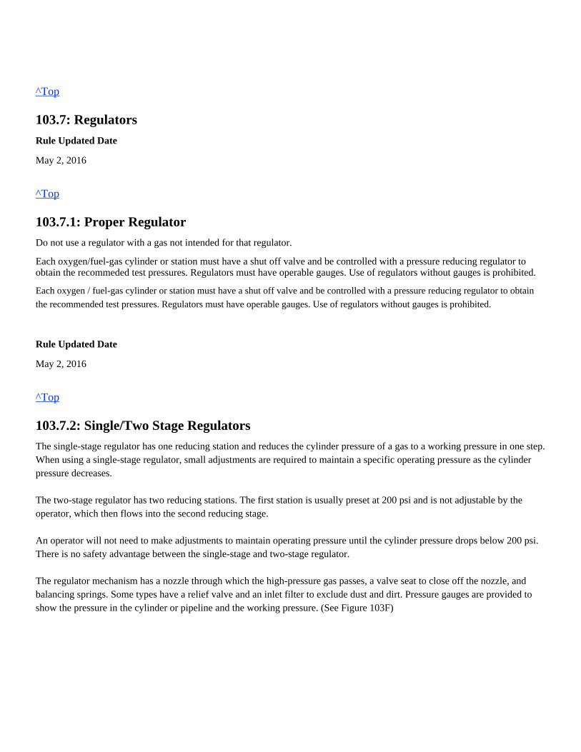
The single-stage regulator has one reducing station and reduces the cylinder pressure of a gas to a working pressure in one step.When using a single-stage regulator, small adjustments are required to maintain a specific operating pressure as the cylinderpressure decreases. The two-stage regulator has two reducing stations. The first station is usually preset at 200 psi and is not adjustable by theoperator, which then flows into the second reducing stage. An operator will not need to make adjustments to maintain operating pressure until the cylinder pressure drops below 200 psi.There is no safety advantage between the single-stage and two-stage regulator. The regulator mechanism has a nozzle through which the high-pressure gas passes, a valve seat to close off the nozzle, andbalancing springs. Some types have a relief valve and an inlet filter to exclude dust and dirt. Pressure gauges are provided toshow the pressure in the cylinder or pipeline and the working pressure. (See Figure 103F)
Rule Updated Date
May 2, 2016
^Top
103.7.3: Connections and Adaptors
Do not force connections. If the thread does not run easily, usually the wrong sized regulator is being applied. Use a standardadapter between the cylinder and the regulator if required. "Tee" or "Y" type connectors are prohibited.
Rule Updated Date
May 2, 2016
^Top
103.7.4: Connecting Regulators
Before connecting regulators to cylinders, welders must open the cylinder valve slightly to blow out any foreign matter.
Rule Updated Date
May 2, 2016
^Top
103.7.5: Protecting Regulators
Protect regulators when not in use by:
The valve should be opened approximately one-quarter turn and closed immediately.Do not open a fuel-gas valve near other welding work or near sparks, flame or other possible sources of ignition.
Prevent a gas mixture from accumulating in the hose when either hose is being relieved of pressure by closing the valve of theother hose. This will prevent flashback, which could damage the torch, hose or pressure regulator.
Rule Updated Date
May 2, 2016
^Top
103.8: Cylinder Valves
Rule Updated Date
May 2, 2016
^Top
103.8.1: Opening Cylinder Valves
Pressure adjusting screws must be fully released before attaching regulator to cylinder. If regulators are already attached tocylinders, relieve pressure on adjusting screws before opening cylinder valve. When opening a cylinder valve, stand to oneside, away from the gauge faces and the front of the regulator. Where a special wrench is required, it must be left in position onthe valve stem while the cylinder is in use, in the event fuel-gas flow must be quickly turned off in an emergency.Return the cylinder to the vendor if oxygen valve cannot be opened by hand. Do not use a hammer or wrench to open anoxygen cylinder valve.
Rule Updated Date
May 2, 2016
^Top
103.8.2: Oxygen Cylinder Valve
Most oxygen cylinder valves are double seated and are designed to be used in the fully open or fully closed position. Valvemay leak if only partially opened.
Slowly open the oxygen cylinder valve until the high pressure gauge indicates full pressure, then fully open the valve.
Rule Updated Date
May 2, 2016
Closing cylinder valves.Draining hoses at the torch.Releasing pressure on the diaphragm.
Place hand around oxygen cylinder knob, not on top of it when initially opening valve.
^Top
103.8.3: Acteylene Cylinder Valve
Acetylene cylinder valves are of a single seat design.
Do not place tools or other items in the recessed top of a cylinder as this may damage the safety plugs or interfere with quicklyclosing the valve.
Rule Updated Date
May 2, 2016
^Top
103.8.4: Propane Cylinder Valve
Propane cylinder valves are double seated and are designed to be used in the fully open or fully closed position. Valve mayleak if only partially opened.
Rule Updated Date
May 2, 2016
^Top
103.8.5: Closing Valves
Valves of cylinders and stations on piped and manifold systems must be closed when not in use. When work is stopped orcompleted, or when the operator leaves the equipment, valves must be operated to relieve pressure on regulators and hoses.
Rule Updated Date
May 2, 2016
^Top
103.8.6: Clogged Valves
Do not open an acetylene cylinder valve more than 1-1/2 turns. This will allow the cylinder valve to be quickly shut offin case of an emergency.Leave the T-wrench on the acetylene cylinder valve stem in case an emergency arises.
Slowly open the propane cylinder valve until the high pressure gauge indicates full pressure, then fully open the valve.
If ice or snow clogs fuel-gas cylinder valves, use warm or medium hot water to thaw them. Do not use boiling water, since itmay loosen fusible plugs. Do not use any type of flame to thaw fuel-gas cylinder valves.
Rule Updated Date
May 2, 2016
^Top
103.9: Torch Valves
Rule Updated Date
May 2, 2016
^Top
103.9.1: Torch Valve Operation
Ensure torch valves are open when changing or adjusting pressure on regulators so gauges indicate actual operating pressures.
Rule Updated Date
May 2, 2016
^Top
103.10: Hoses
Rule Updated Date
May 2, 2016
^Top
103.10.1: Hose Description and Use
Hoses are provided with connections that allow proper attachment to regulators and torches.
Do not exceed pressures authorized for welding or cutting.
Fuel-gas hose fittings have left-hand threads which are identified by notches.Oxygen hose fittings have right-hand threads.
When using oxy-fuel equipment, use only equipment designed for the gas being used. When not in use, oxygen and fuel-gashoses must be properly stored to prevent damage. Oxygen and fuel-gas hoses must be inspected prior to each use. Hoses with leaks, wear or other defects must be repaired orreplaced.Connecting more than one length of hose together is not desirable, but when necessary, all connections must be tight.Hoses must be protected from being stepped on, run over, kinked or tangled.When lengths of oxygen and fuel-gas hose are taped together for convenience and to prevent tangling, not more than 4 inchesout of 12 inches shall be covered by tape.Two common hose types are:1. Grade – "T": This hose is considered a multi-fuel hose. Different fuel-gases, i.e., acetylene, propane, natural gas, propyleneand others can be used but not used alternately through the same hose.
Grade – "T" hose is manufactured in different diameters and has a flame resistant layer that won't sustain a fire.
2. Grade –"R": This hose is manufactured for use with acetylene fuel-gas only.Grade –"R" hose resembles Grade –"T" hose, but will deteriorate from the inside out if an alternate fuel-gas passes through thehose. An "R" grade hose does not have the same flame resistant layer. Information, including hose type and diameter is stamped along the entire length of hose when manufactured. These stampedmarkings will wear off over time but may still be visible near where it is attached to regulators or hose reels.Color-codes for hose are:Red - Combustible gasesGreen - OxygenHose must be used only with the gases for which it is intended.Hose length and diameter will affect stated pressures for equipment used.
Rule Updated Date
May 2, 2016
^Top
103.10.2: Hose Connections
Blow out new hose, with gas for which the hose will be used, to remove residue. In assembling hose connections, only crimpferrules will be used.
Rule Updated Date
May 2, 2016
^Top
103.11: Torches
Track welders are required to use 3/8 inch ID Grade – "T" hose.
103.11: Torches
Torch handles and attachments must be maintained in good condition and carefully handled. When not in use, valves must beclosed and torch stored in a safe place.
Rule Updated Date
May 2, 2016
^Top
103.11.1: Handle
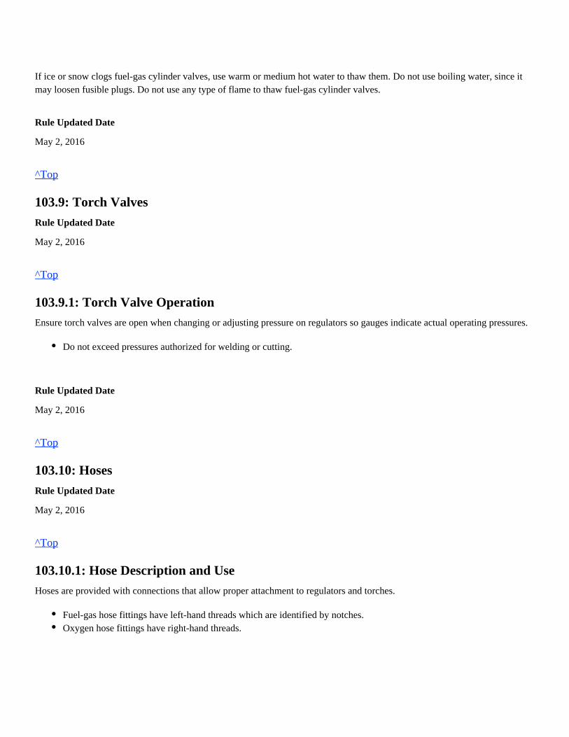
Track welders must use a Victor HD310c or equivalent torch handle when performing welding duties. A Victor 315c orequivalent will not provide the required volume needed for thermite welding (See Figure 103G) and must not be used.
Rule Updated Date
May 2, 2016
^Top
103.11.2: Flashback Arrestors
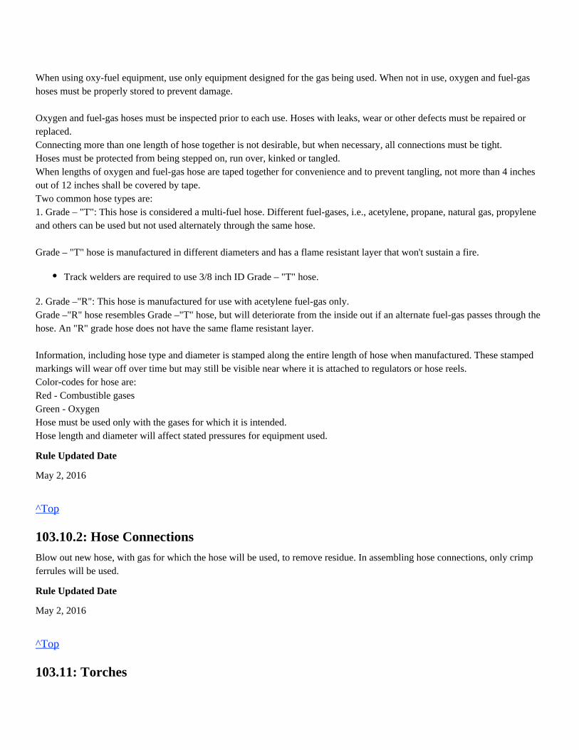
Ensure approved flashback arrestors are applied at the torch.
Flashback arrestors are available in two types - torch mount or regulator mount.Ensure that the proper flashback arrestor is applied.Proper stamping can identify specific arrestor type.(See Figure 103H).Flashback arrestors extinguish a fire within the torch, preventing the fire from spreading back toward the cylinders.A flashback may occur due to dirty tips, lack of adequate fuel-gas pressure for tip size being used, or fuel-gas cylindersnearly empty. Should a flashback occur, determine its cause and correct before resuming operations.If a flashback occurs, immediately shutoff the oxygen valve on the torch handle if welding, or the cutting attachment ifcutting.
Rule Updated Date
May 2, 2016
^Top
103.11.3: Use of in-line Pressure Gauges
In-line gauges must be installed into oxy-fuel system when thermite welding. Gauges wil be installed between the torch handleand flashback arrestors.
Rule Updated Date
May 2, 2016
^Top
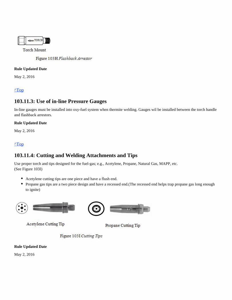
103.11.4: Cutting and Welding Attachments and Tips
Use proper torch and tips designed for the fuel-gas; e.g., Acetylene, Propane, Natural Gas, MAPP, etc.(See Figure 103I)
Rule Updated Date
May 2, 2016
Acetylene cutting tips are one piece and have a flush end.Propane gas tips are a two piece design and have a recessed end.(The recessed end helps trap propane gas long enoughto ignite)
^Top
103.11.5: Torch Precautions
When working with torches:
Rule Updated Date
May 2, 2016
^Top
103.12: Equipment Setup
When setting up welding and cutting equipment, it is important that all operations be performed systematically. The followingset-up procedures will assure safety to the operator and the apparatus. Note: Comply with instructions stated in the fire prevention plan when using oxy-fuel equipment.
Rule Updated Date
May 2, 2016
^Top
103.12.1: Cylinder Use
When working with gas cylinders:1. Place the oxygen and fuel-gas cylinders on a level floor (if they are not mounted on a truck), and tie them securely to awork bench, post, wall, or other secure anchorage to ensure the cylinders remain upright.2. Remove the valve protecting caps.3. Open the fuel-gas valve for an instant, then close to blow out any dirt or foreign matter that may have accumulated duringshipment or storage.4. Open the oxygen gas valve for an instant, then close.Note: Do not stand facing cylinder valve outlets when opening cylinder valves
Rule Updated Date
May 2, 2016
Ensure that the gas stream is not directed toward yourself or others.Keep the flame and sparks directed away from personnel, flammables, and equipment.Torch should be momentarily purged prior to lighting to ensure flow of oxygen and fuel-gas.Do not use the torch as a hammer, scraper or for other than its intended purpose.
^Top
103.12.2: Pressure Regulators
1. Check the regulator fittings for dirt and obstructions. Also check threads of cylinders and regulators for imperfections.2. Connect the fuel-gas regulator to the fuel-gas cylinder and the oxygen regulator to the oxygen cylinder. Use an appropriatewrench and tighten the connecting nuts to prevent leakage.3. Ensure there is no pressure on the regulator adjusting screws by turning counter-clockwise.4. Check hose for defects including burns, nicks and bad fittings.5. Connect the red hose to the fuel-gas regulator and the green hose to the oxygen regulator. Secure connecting nuts tightly toensure leak-proof seating.
Note: Fuel-gas hose connections have left-hand threads and are notched for identification.
6. Open the cylinder valves slowly. Read the high-pressure gauges to check the cylinder gas pressure.7. Connect the red fuel-gas hose to the flashback arrestor mounted on the torch handle. Connect the green oxygen hose to theflashback arrestor mounted on the torch handle.
Rule Updated Date
May 2, 2016
^Top
103.13: Leak Test
The system must be tested for leaks:
When checking the system for leaks, do the following:
a. If the High Pressure gauge reading decreases, a leak is present at the cylinder valve or inlet connection.Perform thefollowing steps:
Prior to initial use each day or shift.When combination torches have been converted or altered.When the torch equipment is suspected of being damaged.When a flashback has occurred.When new torch equipment is installed.
1.
2.
3.
4.
5.
6.
With the oxygen cylinder valve open, adjust the oxygen regulator to deliver 20 psig.
With the fuel-gas cylinder valve open, adjust the fuel-gas regulator to deliver 10 psig.
Ensure the oxygen and fuel-gas control valves on the torch handle are closed.
Close the oxygen and fuel-gas cylinder valves.
Turn the adjusting screws counterclockwise one turn.
Observe the gauges on both regulators for 2 minutes. If the gauge readings do not change, the system is leak tight. If thereis a leak, use an approved leak detection solution or soap and water to locate it.
b. If the Low Pressure gauge reading decreases, a leak is present at the regulator outlet connection; within the hose; atthe torch inlet connection; or at the control valves on the torch handle.Perform the following steps:
After testing the system and verifying that no leaks exist, the equipment may be used.
Use the appropriate form 24249 to record the inspection information, including the inspection date, gang#, if defect is found,employee signature, corrective action (if applicable) for later review by a welding supervisor.
Completed forms must be sent to the track welding manager.
Form 24249 can be accessed on the UP web under the HR Craft Training page or ordered through the online requisitionsystem.
Rule Updated Date
May 2, 2016
^Top
103.14: Igniting and Extinguishing Torch
Use only a standard friction lighter to ignite all oxygen/fuel-gas equipment or fuel-gas equipment.
When igniting a torch, never point the torch toward others or flammable materials.A lighted torch must not be:
Rule Updated Date
May 2, 2016
Tighten the inlet connection after releasing pressure from the regulator.If the inlet connection continues to leak, have the regulator repaired by a qualified repair technician.Never tighten a cylinder valve.If the cylinder valve is leaking, remove the regulator from the cylinder and place the cylinder outdoors.Notify your gas supplier immediately.
After the pressure has been released from the system, tighten the regulator outlet connection and the torch handleinlet connection.If these connections continue to leak, have the regulator or torch handle repaired by a qualified technician.Replace leaking hoses.Tighten or replace connections where leaks are found.
Laid down.Passed from one person to another.Kept in your hand when climbing.Left unattended
^Top
103.14.1: Igniting Oxy-acetylene Torch
To properly ignite an Oxy-acetylene torch, use the following sequence:1. Open the acetylene valve on the torch handle and ignite the gas.2. Adjust flame so that the black carbon smoke disappears.3. Introduce oxygen and adjust to a neutral flame.
Rule Updated Date
May 2, 2016
^Top
103.14.2: Extinguishing Oxy-acetylene Torch
To properly shut down an Oxy-acetylene torch, use the following sequence:1. Shut off the oxygen valve on the torch handle.2. Shut off the acetylene valve on the torch handle.
By following this sequence, both sides of the system are checked for leaks.1. If a "pop" is heard, the oxygen valve is leaking.2. If a small flame is still burning on the tip of the torch, the acetylene valve is leaking.
Tighten the leaking valve with a wrench or take to a qualified repair facility.Note: Shutting off the acetylene valve first will create a "pop" every time and result in soot being blown back into the torch.
Rule Updated Date
May 2, 2016
^Top
103.14.3: Igniting Oxy-propane Torch
To properly ignite an Oxy-propane torch, use the following sequence:
Note: When igniting the torch, if there is a gap between the torch tip and the flame, too much propane is present. Extinguishthe flame by closing the propane valve first, then closing the oxygen valve and start over.
Rule Updated Date
May 2, 2016
1.
2.
3.
Slightly open the propane valve.
Open the oxygen valve about 1/4 turn (slightly more than the propane valve).
Ignite the torch, adjust to a neutral flame.
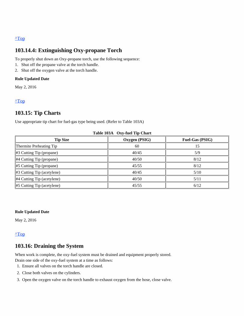
^Top
103.14.4: Extinguishing Oxy-propane Torch
To properly shut down an Oxy-propane torch, use the following sequence:1. Shut off the propane valve at the torch handle.2. Shut off the oxygen valve at the torch handle.
Rule Updated Date
May 2, 2016
^Top
103.15: Tip Charts
Use appropriate tip chart for fuel-gas type being used. (Refer to Table 103A)
Table 103A Oxy-fuel Tip Chart
Tip Size Oxygen (PSIG) Fuel-Gas (PSIG)
Thermite Preheating Tip 60 15
#3 Cutting Tip (propane) 40/45 5/9
#4 Cutting Tip (propane) 40/50 8/12
#5 Cutting Tip (propane) 45/55 8/12
#3 Cutting Tip (acetylene) 40/45 5/10
#4 Cutting Tip (acetylene) 40/50 5/11
#5 Cutting Tip (acetylene) 45/55 6/12
Rule Updated Date
May 2, 2016
^Top
103.16: Draining the System
When work is complete, the oxy-fuel system must be drained and equipment properly stored.Drain one side of the oxy-fuel system at a time as follows:1.
2.
3.
4.
Ensure all valves on the torch handle are closed.
Close both valves on the cylinders.
Open the oxygen valve on the torch handle to exhaust oxygen from the hose, close valve.
Rule Updated Date
May 2, 2016
^Top
4.
5.
6.
Release the pressure on the oxygen regulator by turning the pressure adjustment screw counter clockwise.
Open the fuel-gas valve on the torch handle to exhaust fuel-gas from the hose, close valve.
Release the pressure on the fuel-gas regulator by turning the pressure adjustment screw counter clockwise.
Union Pacific Rules Track Welding Rules and Procedures
104.0: EQUIPMENT
104.1: Equipment Description
Rule Updated Date
March 1, 2007
^Top
104.1.1: Rail Saws
A rail saw can be powered by gasoline, hydraulic or electric. When operating a rail saw:
Rule Updated Date
May 2, 2016
^Top
104.1.2: Grinders
104.1: Equipment Description104.1.1: Rail Saws104.1.2: Grinders104.1.3: Hydraulic Rail Pullers104.1.4: Wire Feeders
The guide support arm must be used when cutting rail (freehand cutting is prohibited).Warn others that you are about to begin cutting rail.Personnel are prohibited from standing in front of the rail saw while cutting rail.Required Personal Protective Equipment (PPE) must be used when operating a rail saw.Inspect equipment regularly to ensure it is operating safely and efficiently.Do not fuel gasoline powered rail saws closer than 20 feet from where the rail is to be cut.
Straight Shaft Grinders - A straight shaft grinder can either be hydraulic or electric, and with the appropriate abrasivewheels can be used for many purposes. This can include maintenance grinding, removing metal flow, slotting andwelding preparation. This type of grinder is not recommended for finishing rail or component surfaces.
Rule Updated Date
May 2, 2016
^Top
104.1.3: Hydraulic Rail Pullers
A rail puller is used to pull rail together at pull-aparts, service failures or while installing thermite welds.
Review and be familiar with manufacturer's operating and maintenance manuals before operating equipment.
Daily inspection and maintenance is required to ensure rail puller is in safe operating condition before each use.
Perform daily maintenance as follows:
Annual maintenance is required to ensure proper operation of the rail puller. When disassembling, only remove one corner at a time.
Disassemble and clean all four corners of the rail puller as follows:
Angle Grinders - An angle grinder can either be hydraulic or electric and is used primarily to finish grind rail andcomponent surfaces and radii. This type of grinder can also be used in maintenance grinding, removing metal flow andwelding preparation.Profile Grinder - A profile grinder can either be hydraulic, gas or electric and is used primarily to grind thermite weldsand flash butt welds. This type of grinder, if designed for the task, can also be used to grind the surface of rail ends andfrogs.Switch Grinders - A switch grinder can either be hydraulic, gas or electric and is designed for maintaining turnouts byremoving metal flow and restoring radius on stock rails, switch points and frogs.Frog Grinders - A frog grinder can either be hydraulic or electric and is used to grind frog flange-ways and runningsurfaces after weld repairs. This type of grinder can also be used for maintenance grinding, including removing metalflow and restoring radius.Web Grinder - A web grinder is generally powered by hydraulics and is designed to grind the web and base of boththermite and electric flash butt welds.Bull Nose Grinder - A bull nose grinder is designed specifically to de-burr and chamfer (bevel) bolt holes. Separatebull-nose grinding stones are available and can be used on portable hand tools or impact tool with appropriateadaptors.
If manuals are not available, contact your supervisor to obtain a copy.
Jaws have been cleaned with a wire brush.
Pivot areas have been lubricated.
Only trained employees are allowed to complete this process.
Remove latch pin and tie rod from swing arm.
Remove swing arm from bracket.
Remove rail jaw from swing arm.
Properly clean all pivot surfaces with brake cleaner, wire brush, wire wheel or flap wheel and wipe clean with a towel. Lubricate all
pivot surfaces with anti-seize before reassembly.
Ensure rail puller jaws are installed with the arrows pointing towards the center of rail puller.
Any time a rail puller is used, and only authorized personnel are permitted to operate equipment.caution must be taken
Follow these procedures when using a rail puller:
In addition, follow these instructions when using the old style RPE 120 Simplex Rail Puller with removable wedges.
A rail puller should be used on closure welds when one or more of the following conditions apply:
A. The rail temperature is lower than the rail laying temperature.
(Refer to standard drawing 0045 to obtain rail-laying temperature)
B. The reference marks indicate that you are adding rail.
All other individuals must not be near rail puller when in operation.
No one is allowed to be near the ends of the rail puller when under pressure and standing at the end of a rail puller under
pressure is prohibited.
Low rail joints must be raised and ties tamped before setting rail puller on the rail.
Remove by grinding, any raised lettering on the rail or other protrusions where jaws will contact rail.
Remove dirt or grease from this area using a wire brush or torch if necessary. Clean and inspect the jaws for conditions that
could reduce gripping.
Pre-align rail ends to be welded to an approximate crown before pulling.
Remove enough rail anchors or fasteners to allow the rail to move the required distance to complete the pull. Removing
anchors or fasteners allows the rail to move freely and not over exert the rail puller.
If the desired pull cannot be achieved, release the rail puller, remove additional anchors or fasteners and pull again.
Do not strike any portion of the rail puller or track structure while the rail puller is under load, including removing or applying rail
anchors or fasteners.
Striking the rail puller or track structure may cause the rail puller to lose grip.
Alignment plates must be used for aligning rail.
Ensure safety guards and rod latches are in place and functioning properly before use.
Do not use a rail puller if guards or latches are missing or damaged.
Clean and inspect the wedges for conditions that could reduce gripping.
Apply a light coat of oil or grease to the backside of wedges that contact the bracket.This will help when removing the
expander.
Insert the wedges with the teeth facing the rail.
Store rods and wedges properly to prevent damage.
C. A decrease in rail temperature may occur during the welding process, such as rapidly changing weather conditions.
When working in close proximity to another gang using a rail puller, permission must be obtained solely from the Manager of Track
to use the second rail puller on the same rail.Welding
Rule Updated Date
May 2, 2016
^Top
104.1.4: Wire Feeders
Wire feeders are connected to the welding machine by the positive electrode cable and allow electric arc welding tobe performed when making repairs to track components or welding pieces of metal together. Approved wire feedersfor track welding must have 5/64" drive rolls, set to indicate amperage instead of inches-per-minute and run onConstant Voltage (CV) if welding machine has the capability.
Rule Updated Date
May 2, 2016
^Top
Welding hood properly shaded with hard hat (unless using the approved non-hard hat PAPR welding hood), hearingprotection, safety glasses, leather welding gloves, welding jacket or welding sleeves, approved safety-toe boots andflame resistant clothing.
Hard hat, hearing protection, dual eye protection as follows:
leather welding gloves, welding jacket or welding sleeves, leather leggings, approved safety-toe boots and flameresistant clothing.
Hard hat, hearing protection, type of eye protection as follows:
work gloves, welding jacket or welding sleeves, leather leggings, approved safety-toe boots and flame resistantclothing.
Union Pacific Rules Track Welding Rules and Procedures
105.0: WELDING RAIL ENDS
105.1: Personal Protective Equipment (PPE)
Task Required PPE
Abrasive
Grinding
See respiratory policy for respirator requirement.
Oxy-fuel
/Fuel-gas
Heating
See respiratory policy for respirator requirement.
Electric
Arc
Welding
See respiratory policy for respirator requirement.
105.1: Personal Protective Equipment (PPE)105.2: Purpose of Welding Ends105.3: Alloy Rail Precaution105.4: Use Proper Stick and Wire Electrodes105.5: Prepare for Welding105.6: Determine Weld Length105.7: Remove Defective Material105.8: Preheat and Maintain Inter-Pass Temperature105.9: Apply Weld105.10: Post Heat105.11: Temporary Rail Ends Buildup105.13: Slot Rail Ends105.12: Surface Grind Rail Ends
1.
2.
Welding hood with clear lens or in grind mode with safety glasses, or
Wrap-around face shield with goggles or safety glasses (#5 shade must be worn),not
1.
2.
Wrap-around face shield with goggles or safety glasses. or(one has to be shade #5),
Mono-goggle XTR shade #5 with safety glasses can be used as an alternative,
Rule Updated Date
May 2, 2016
^Top
105.2: Purpose of Welding Ends
The purpose of welding rail ends is to:
Do not weld rail ends to:
Do not weld gage face of rail.
Rule Updated Date
May 2, 2016
General Order
Effective Date: May 2, 2016
^Top
105.3: Alloy Rail Precaution
Preheating and postheating procedures are different for alloy and non-alloy rail. Chrome-vanadium and chrome-moly rails areextremely sensitive to rapid cooling. Additional care must also be used when working with alloy rail, including:
Rule Updated Date
May 2, 2016
Correct rail end batter.Repair chipped rail ends.Fit a good section of rail next to a worn section of rail.
Correct drooped ends or surface bent rail.Compensate for worn joint bars, loose bolts or poor track surface.Repair engine burns (wheel burns) or crushed headsDefect must be replaced with at least a 15 ft. rail.
1.
2.
3.
4.
Not installing alloy rail as replacement rail.
Not over heating (bluing) alloy rail when drilling or cutting.
Using sharp drill bits of the proper size and lubricant when drilling bolt holes.
Not performing arc welding on alloy rail when the ambient temperature is below 32° F.
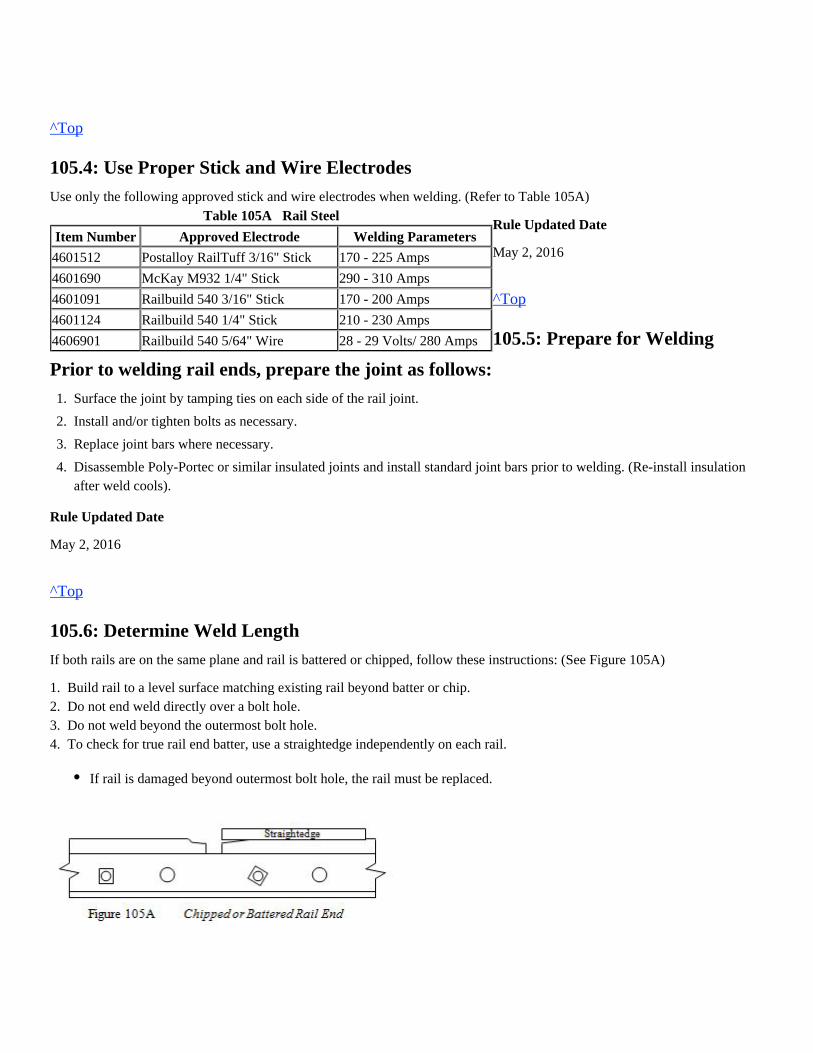
Table 105A Rail Steel
Item Number Approved Electrode Welding Parameters
4601512 Postalloy RailTuff 3/16" Stick 170 - 225 Amps
4601690 McKay M932 1/4" Stick 290 - 310 Amps
4601091 Railbuild 540 3/16" Stick 170 - 200 Amps
4601124 Railbuild 540 1/4" Stick 210 - 230 Amps
4606901 Railbuild 540 5/64" Wire 28 - 29 Volts/ 280 Amps
^Top
105.4: Use Proper Stick and Wire Electrodes
Use only the following approved stick and wire electrodes when welding. (Refer to Table 105A)
Rule Updated Date
May 2, 2016
^Top
105.5: Prepare for Welding
Prior to welding rail ends, prepare the joint as follows:
Rule Updated Date
May 2, 2016
^Top
105.6: Determine Weld Length
If both rails are on the same plane and rail is battered or chipped, follow these instructions: (See Figure 105A)
1. Build rail to a level surface matching existing rail beyond batter or chip.2. Do not end weld directly over a bolt hole.3. Do not weld beyond the outermost bolt hole.4. To check for true rail end batter, use a straightedge independently on each rail.
1.
2.
3.
4.
Surface the joint by tamping ties on each side of the rail joint.
Install and/or tighten bolts as necessary.
Replace joint bars where necessary.
Disassemble Poly-Portec or similar insulated joints and install standard joint bars prior to welding. (Re-install insulationafter weld cools).
If rail is damaged beyond outermost bolt hole, the rail must be replaced.
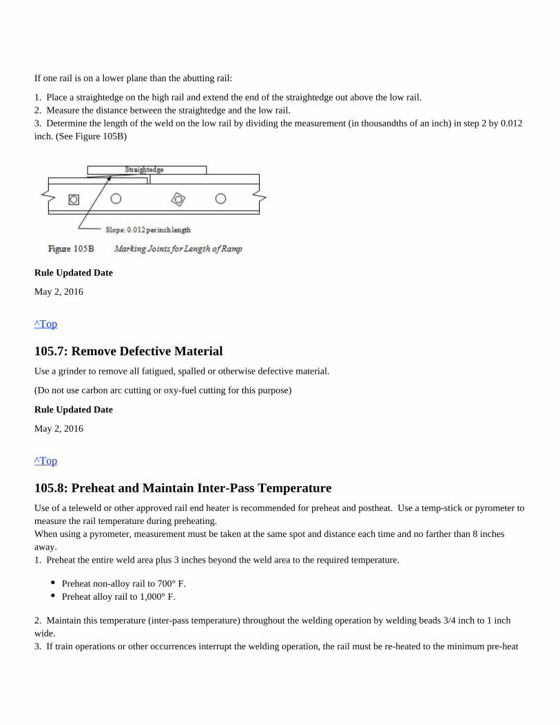
If one rail is on a lower plane than the abutting rail:
1. Place a straightedge on the high rail and extend the end of the straightedge out above the low rail.2. Measure the distance between the straightedge and the low rail.3. Determine the length of the weld on the low rail by dividing the measurement (in thousandths of an inch) in step 2 by 0.012inch. (See Figure 105B)
Rule Updated Date
May 2, 2016
^Top
105.7: Remove Defective Material
Use a grinder to remove all fatigued, spalled or otherwise defective material.
(Do not use carbon arc cutting or oxy-fuel cutting for this purpose)
Rule Updated Date
May 2, 2016
^Top
105.8: Preheat and Maintain Inter-Pass Temperature
Use of a teleweld or other approved rail end heater is recommended for preheat and postheat. Use a temp-stick or pyrometer tomeasure the rail temperature during preheating.When using a pyrometer, measurement must be taken at the same spot and distance each time and no farther than 8 inchesaway.1. Preheat the entire weld area plus 3 inches beyond the weld area to the required temperature.
2. Maintain this temperature (inter-pass temperature) throughout the welding operation by welding beads 3/4 inch to 1 inchwide.3. If train operations or other occurrences interrupt the welding operation, the rail must be re-heated to the minimum pre-heat
Preheat non-alloy rail to 700° F.Preheat alloy rail to 1,000° F.
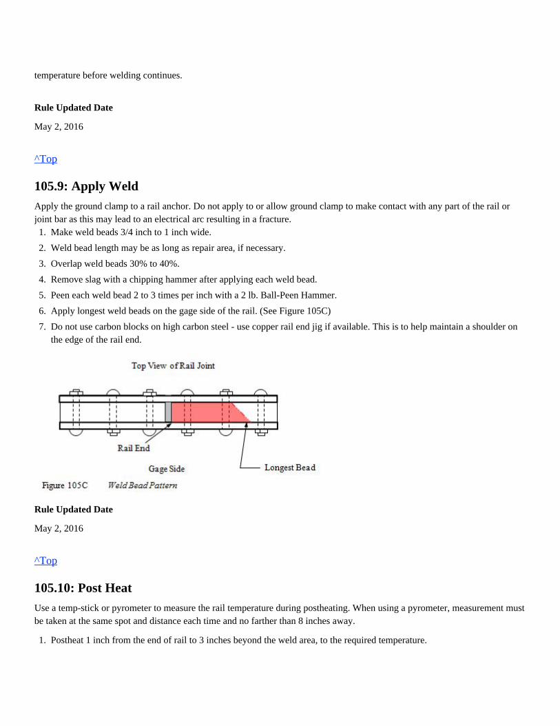
temperature before welding continues.
Rule Updated Date
May 2, 2016
^Top
105.9: Apply Weld
Apply the ground clamp to a rail anchor. Do not apply to or allow ground clamp to make contact with any part of the rail orjoint bar as this may lead to an electrical arc resulting in a fracture.
Rule Updated Date
May 2, 2016
^Top
105.10: Post Heat
Use a temp-stick or pyrometer to measure the rail temperature during postheating. When using a pyrometer, measurement mustbe taken at the same spot and distance each time and no farther than 8 inches away.
1.
2.
3.
4.
5.
6.
7.
Make weld beads 3/4 inch to 1 inch wide.
Weld bead length may be as long as repair area, if necessary.
Overlap weld beads 30% to 40%.
Remove slag with a chipping hammer after applying each weld bead.
Peen each weld bead 2 to 3 times per inch with a 2 lb. Ball-Peen Hammer.
Apply longest weld beads on the gage side of the rail. (See Figure 105C)
Do not use carbon blocks on high carbon steel - use copper rail end jig if available. This is to help maintain a shoulder onthe edge of the rail end.
1.
2.
Postheat 1 inch from the end of rail to 3 inches beyond the weld area, to the required temperature.
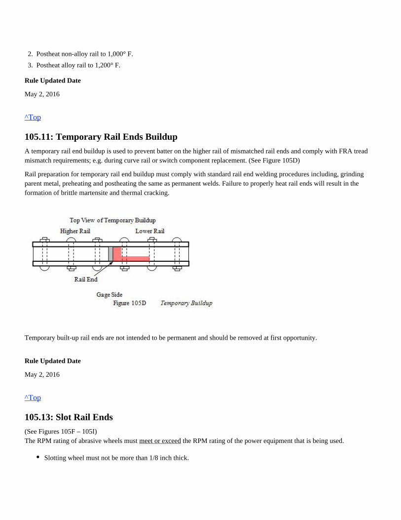
Rule Updated Date
May 2, 2016
^Top
105.11: Temporary Rail Ends Buildup
A temporary rail end buildup is used to prevent batter on the higher rail of mismatched rail ends and comply with FRA treadmismatch requirements; e.g. during curve rail or switch component replacement. (See Figure 105D)
Rail preparation for temporary rail end buildup must comply with standard rail end welding procedures including, grindingparent metal, preheating and postheating the same as permanent welds. Failure to properly heat rail ends will result in theformation of brittle martensite and thermal cracking.
Temporary built-up rail ends are not intended to be permanent and should be removed at first opportunity.
Rule Updated Date
May 2, 2016
^Top
105.13: Slot Rail Ends
(See Figures 105F – 105I)The RPM rating of abrasive wheels must the RPM rating of the power equipment that is being used.meet or exceed
2.
3.
Postheat non-alloy rail to 1,000° F.
Postheat alloy rail to 1,200° F.
Slotting wheel must not be more than 1/8 inch thick.
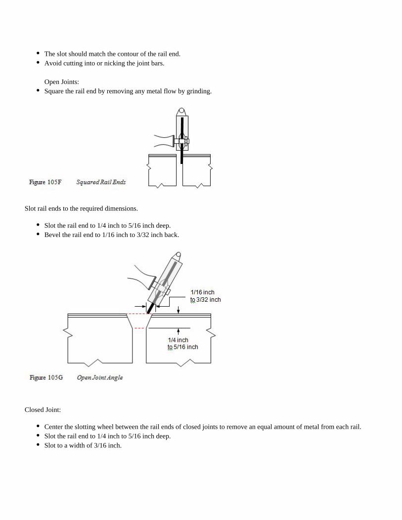
Slot rail ends to the required dimensions.
Closed Joint:
The slot should match the contour of the rail end.Avoid cutting into or nicking the joint bars. Open Joints:Square the rail end by removing any metal flow by grinding.
Slot the rail end to 1/4 inch to 5/16 inch deep.Bevel the rail end to 1/16 inch to 3/32 inch back.
Center the slotting wheel between the rail ends of closed joints to remove an equal amount of metal from each rail.Slot the rail end to 1/4 inch to 5/16 inch deep.Slot to a width of 3/16 inch.
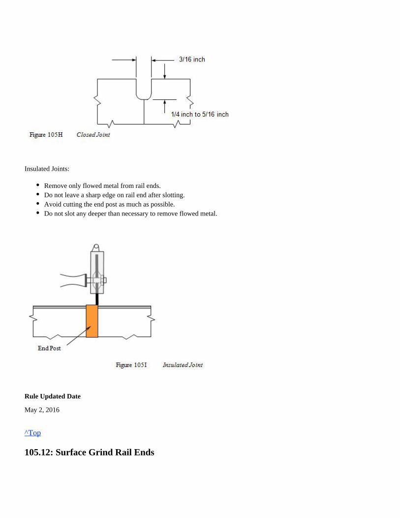
Insulated Joints:
Rule Updated Date
May 2, 2016
^Top
105.12: Surface Grind Rail Ends
Remove only flowed metal from rail ends.Do not leave a sharp edge on rail end after slotting.Avoid cutting the end post as much as possible.Do not slot any deeper than necessary to remove flowed metal.
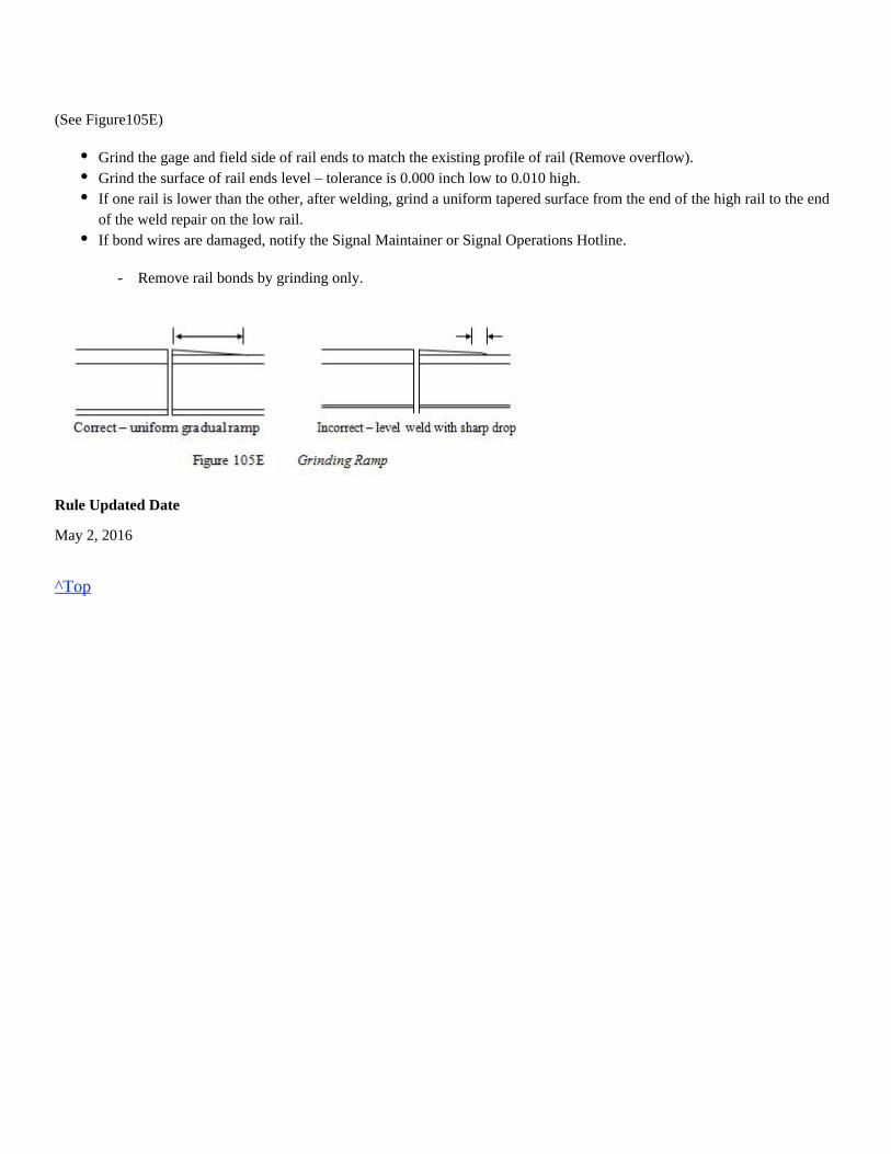
(See Figure105E)
- Remove rail bonds by grinding only.
Rule Updated Date
May 2, 2016
^Top
Grind the gage and field side of rail ends to match the existing profile of rail (Remove overflow).Grind the surface of rail ends level – tolerance is 0.000 inch low to 0.010 high.If one rail is lower than the other, after welding, grind a uniform tapered surface from the end of the high rail to the endof the weld repair on the low rail.If bond wires are damaged, notify the Signal Maintainer or Signal Operations Hotline.
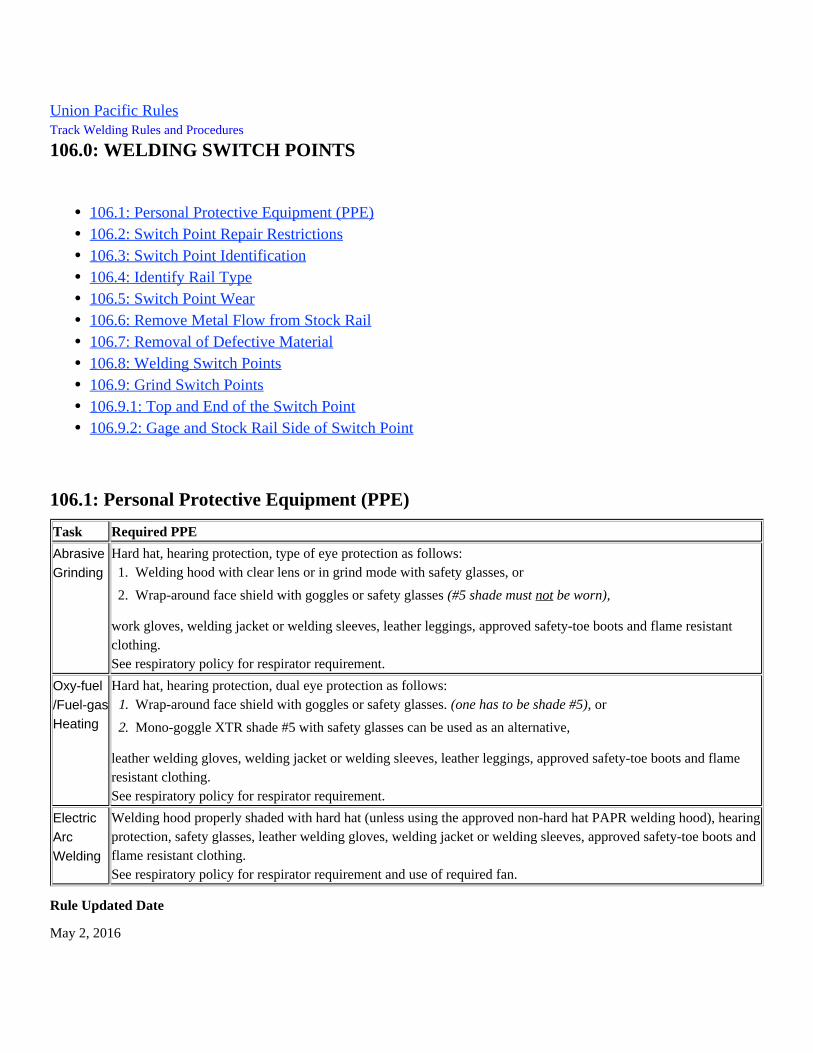
Welding hood properly shaded with hard hat (unless using the approved non-hard hat PAPR welding hood), hearingprotection, safety glasses, leather welding gloves, welding jacket or welding sleeves, approved safety-toe boots andflame resistant clothing.
Hard hat, hearing protection, dual eye protection as follows:
leather welding gloves, welding jacket or welding sleeves, leather leggings, approved safety-toe boots and flameresistant clothing.
Hard hat, hearing protection, type of eye protection as follows:
work gloves, welding jacket or welding sleeves, leather leggings, approved safety-toe boots and flame resistantclothing.
Union Pacific Rules Track Welding Rules and Procedures
106.0: WELDING SWITCH POINTS
106.1: Personal Protective Equipment (PPE)
Task Required PPE
AbrasiveGrinding
See respiratory policy for respirator requirement.
Oxy-fuel/Fuel-gasHeating
See respiratory policy for respirator requirement.
ElectricArcWelding
See respiratory policy for respirator requirement and use of required fan.
Rule Updated Date
May 2, 2016
106.1: Personal Protective Equipment (PPE)106.2: Switch Point Repair Restrictions106.3: Switch Point Identification106.4: Identify Rail Type106.5: Switch Point Wear106.6: Remove Metal Flow from Stock Rail106.7: Removal of Defective Material106.8: Welding Switch Points106.9: Grind Switch Points106.9.1: Top and End of the Switch Point106.9.2: Gage and Stock Rail Side of Switch Point
1.
2.
Welding hood with clear lens or in grind mode with safety glasses, or
Wrap-around face shield with goggles or safety glasses (#5 shade must be worn),not
1.
2.
Wrap-around face shield with goggles or safety glasses. or(one has to be shade #5),
Mono-goggle XTR shade #5 with safety glasses can be used as an alternative,
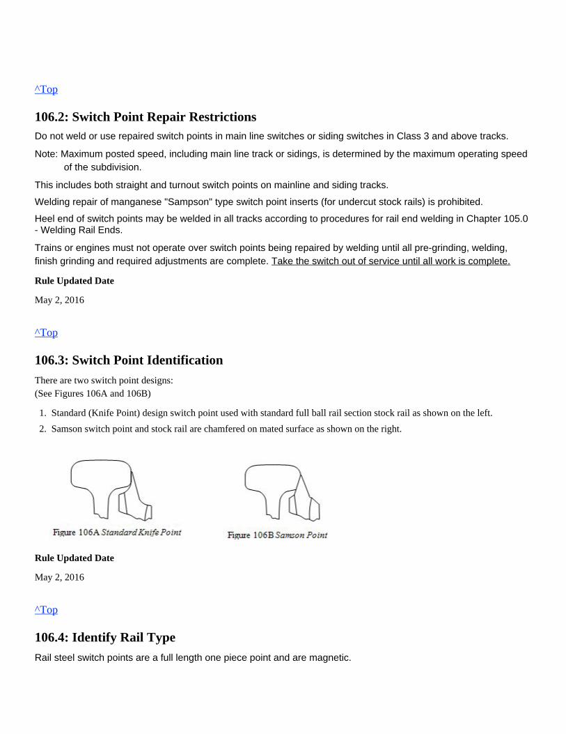
^Top
106.2: Switch Point Repair RestrictionsDo not weld or use repaired switch points in main line switches or siding switches in Class 3 and above tracks.
Note: Maximum posted speed, including main line track or sidings, is determined by the maximum operating speedof the subdivision.
This includes both straight and turnout switch points on mainline and siding tracks.
Welding repair of manganese "Sampson" type switch point inserts (for undercut stock rails) is prohibited.
Heel end of switch points may be welded in all tracks according to procedures for rail end welding in Chapter 105.0- Welding Rail Ends.
Trains or engines must not operate over switch points being repaired by welding until all pre-grinding, welding,finish grinding and required adjustments are complete. Take the switch out of service until all work is complete.
Rule Updated Date
May 2, 2016
^Top
106.3: Switch Point Identification
There are two switch point designs:(See Figures 106A and 106B)
Rule Updated Date
May 2, 2016
^Top
106.4: Identify Rail Type
Rail steel switch points are a full length one piece point and are magnetic.
1.
2.
Standard (Knife Point) design switch point used with standard full ball rail section stock rail as shown on the left.
Samson switch point and stock rail are chamfered on mated surface as shown on the right.
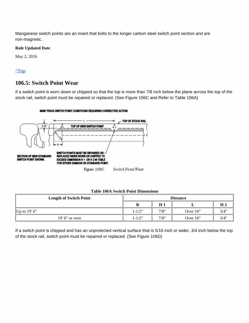
Manganese switch points are an insert that bolts to the longer carbon steel switch point section and arenon-magnetic.
Rule Updated Date
May 2, 2016
^Top
106.5: Switch Point Wear
If a switch point is worn down or chipped so that the top is more than 7/8 inch below the plane across the top of the stock rail, switch point must be repaired or replaced. (See Figure 106C and Refer to Table 106A)
Table 106A Switch Point Dimensions
Length of Switch Point Distance
R H 1 L H 2
Up to 19' 6" 1-1/2" 7/8" Over 10" 3/4"
19' 6" or over 1-1/2" 7/8" Over 16" 3/4"
If a switch point is chipped and has an unprotected vertical surface that is 5/16 inch or wider, 3/4 inch below the top of the stock rail, switch point must be repaired or replaced. (See Figure 106D)
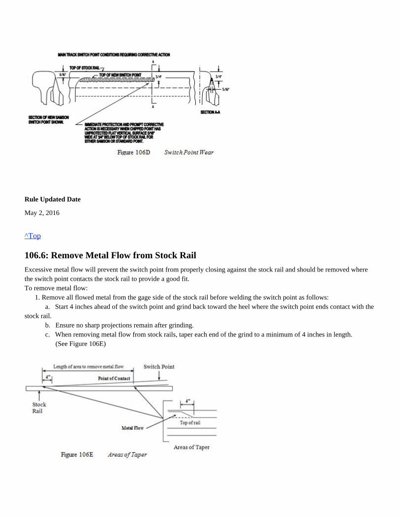
Rule Updated Date
May 2, 2016
^Top
106.6: Remove Metal Flow from Stock Rail
Excessive metal flow will prevent the switch point from properly closing against the stock rail and should be removed wherethe switch point contacts the stock rail to provide a good fit.To remove metal flow: 1. Remove all flowed metal from the gage side of the stock rail before welding the switch point as follows: a. Start 4 inches ahead of the switch point and grind back toward the heel where the switch point ends contact with thestock rail. b. Ensure no sharp projections remain after grinding. c. When removing metal flow from stock rails, taper each end of the grind to a minimum of 4 inches in length. (See Figure 106E)
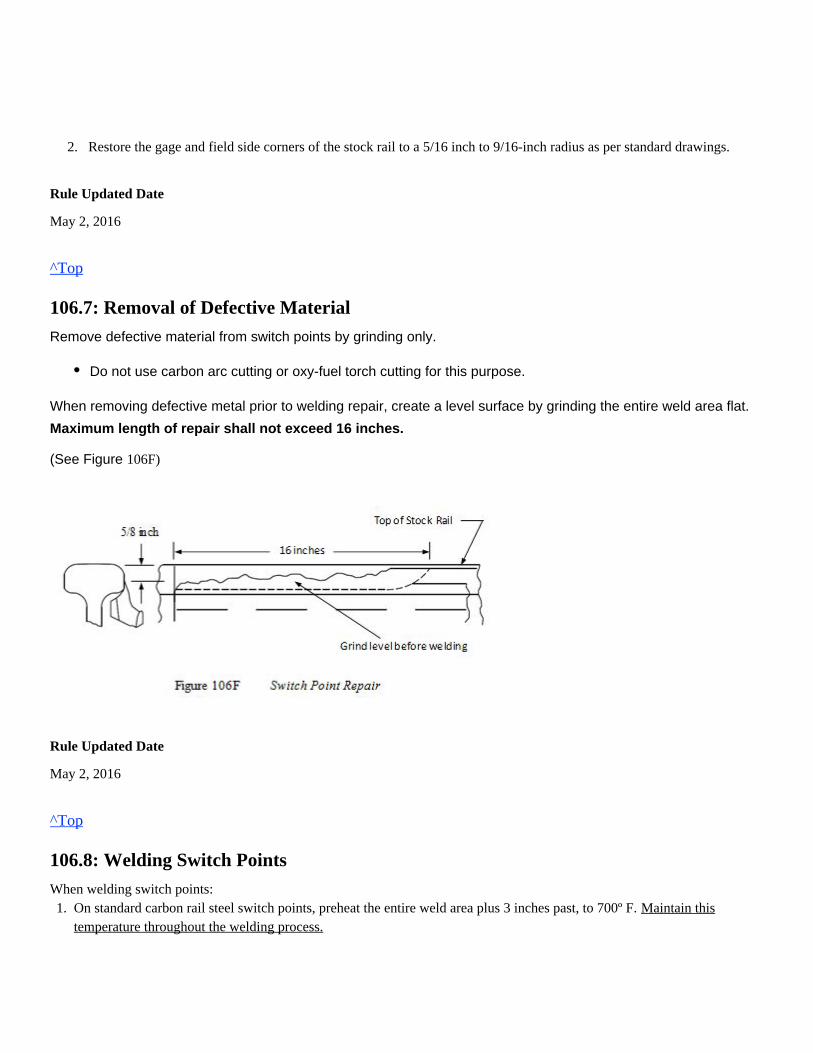
2. Restore the gage and field side corners of the stock rail to a 5/16 inch to 9/16-inch radius as per standard drawings.
Rule Updated Date
May 2, 2016
^Top
106.7: Removal of Defective Material
Remove defective material from switch points by grinding only.
When removing defective metal prior to welding repair, create a level surface by grinding the entire weld area flat.
Maximum length of repair shall not exceed 16 inches.
106F)(See Figure
Rule Updated Date
May 2, 2016
^Top
106.8: Welding Switch Points
When welding switch points:
Do not use carbon arc cutting or oxy-fuel torch cutting for this purpose.
1. On standard carbon rail steel switch points, preheat the entire weld area plus 3 inches past, to 700º F. Maintain thistemperature throughout the welding process.
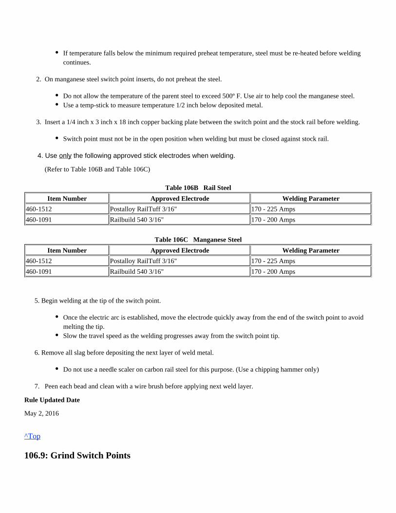
2. On manganese steel switch point inserts, do not preheat the steel.
3. Insert a 1/4 inch x 3 inch x 18 inch copper backing plate between the switch point and the stock rail before welding.
4. Use the following approved stick electrodes when welding. only
(Refer to Table 106B and Table 106C)
Table 106B Rail Steel
Item Number Approved Electrode Welding Parameter
460-1512 Postalloy RailTuff 3/16" 170 - 225 Amps
460-1091 Railbuild 540 3/16" 170 - 200 Amps
Table 106C Manganese Steel
Item Number Approved Electrode Welding Parameter
460-1512 Postalloy RailTuff 3/16" 170 - 225 Amps
460-1091 Railbuild 540 3/16" 170 - 200 Amps
5. Begin welding at the tip of the switch point.
6. Remove all slag before depositing the next layer of weld metal.
7. Peen each bead and clean with a wire brush before applying next weld layer.
Rule Updated Date
May 2, 2016
^Top
106.9: Grind Switch Points
If temperature falls below the minimum required preheat temperature, steel must be re-heated before weldingcontinues.
Do not allow the temperature of the parent steel to exceed 500º F. Use air to help cool the manganese steel.Use a temp-stick to measure temperature 1/2 inch below deposited metal.
Switch point must not be in the open position when welding but must be closed against stock rail.
Once the electric arc is established, move the electrode quickly away from the end of the switch point to avoidmelting the tip.Slow the travel speed as the welding progresses away from the switch point tip.
Do not use a needle scaler on carbon rail steel for this purpose. (Use a chipping hammer only)
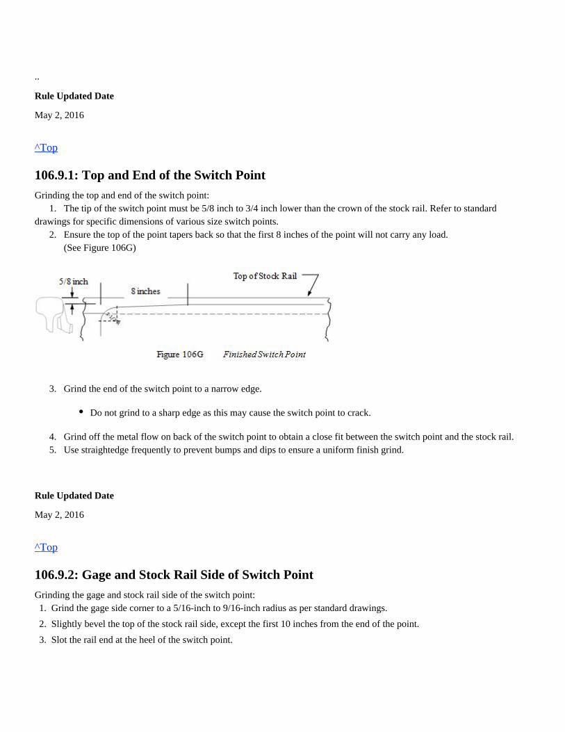
..
Rule Updated Date
May 2, 2016
^Top
106.9.1: Top and End of the Switch Point
Grinding the top and end of the switch point: 1. The tip of the switch point must be 5/8 inch to 3/4 inch lower than the crown of the stock rail. Refer to standarddrawings for specific dimensions of various size switch points. 2. Ensure the top of the point tapers back so that the first 8 inches of the point will not carry any load. (See Figure 106G)
3. Grind the end of the switch point to a narrow edge.
4. Grind off the metal flow on back of the switch point to obtain a close fit between the switch point and the stock rail. 5. Use straightedge frequently to prevent bumps and dips to ensure a uniform finish grind.
Rule Updated Date
May 2, 2016
^Top
106.9.2: Gage and Stock Rail Side of Switch Point
Grinding the gage and stock rail side of the switch point:
Do not grind to a sharp edge as this may cause the switch point to crack.
1.
2.
3.
Grind the gage side corner to a 5/16-inch to 9/16-inch radius as per standard drawings.
Slightly bevel the top of the stock rail side, except the first 10 inches from the end of the point.
Slot the rail end at the heel of the switch point.

Check for proper fit between the switch point and stock rail after all welding and/or grinding operations are completed.Note: Apply grease if available, to help extend the life of the switch point. Always have a Signal Maintainer available when welding or grinding on switches equipped with switch machines, electriclocks or circuit controllers.
Rule Updated Date
May 2, 2016
^Top
Union Pacific Rules Track Welding Rules and Procedures
107.0: FROGS: GENERAL
Chapter Introduction
The installation date will be written on the frog using a white metal marker for warranty purposes.
107.1: Frog Repair Guidelines
When repairing frogs, every effort must be made to complete the welding and grinding process to standard specifications when time
permits. If frog cannot be completed as required, wings and point must be at the same height to evenly support the weight of the train.
A frog that has been temporarily repaired must comply with FRA regulations or appropriate slow order must be provided.
Rule Updated Date
May 2, 2016
^Top
107.1.1: Clamped Frogs
Before welding frogs out of track, clamp them to a rigid support to prevent warping.
Rule Updated Date
March 1, 2007
^Top
107.1.2: Solid Base
107.1: Frog Repair Guidelines107.1.1: Clamped Frogs107.1.2: Solid Base107.1.3: Repairs to Specific Frogs107.1.4: Beyond Main Line Switch107.1.5: Chipped or Battered Rail Ends107.1.6: Reconditioned Manganese Frogs107.2: Frog Identification
Ensure all frogs or other components welded in track are on a solid base and all bolts are tight.
Rule Updated Date
March 1, 2007
^Top
107.1.3: Repairs to Specific Frogs
A. Rail-Bound Manganese Insert Frogs (RBM) RBM frogs in all main line, branch line and other track may be repaired by welding.
B. Rigid Bolted Frogs (Carbon Rail Steel) Do not repair rigid bolted frogs by welding in the field, except on the following tracks:
C. Carbon Steel Spring Rail Frogs Do not repair carbon spring rail frogs by welding except rail ends, forged horn straps and hold-down housing. See instructions 108.5 Weld Spring Rail Frog Horn for repair guidelines and procedures.
D. Manganese Steel Insert Spring Rail Frogs Repair manganese insert spring rail frogs by welding according to the requirements in Chapter 109.0.
E. Solid Manganese Self Guarded (SMSG) Frogs SMSG frogs in all branch line, yard tracks and industry tracks may be repaired by welding.
Heel leg extension rails are made of carbon rail steel, and on specific frogs can be repaired by welding as outlined inChapter 105.0 Rail End Repairs and 109.9 Heel Leg Extension Rail.Conformal RBM frogs have a 1:20 slope and will be maintained to design specifications for grinding maintenance butwelding repairs can be made to accommodate a flat slope.
All repaired frogs must be finish ground to meet FRA specifications for surface wear and flangeway clearance.
For inspection and maintenance practices, refer to Section 5.0 Turnouts in the Engineering Track MaintenanceHand Book.
Branch line track where the maximum authorized speed is 30 MPH or less as designated by the timetable maximumsubdivision speed.Sidings, yard tracks and industry tracks beyond the clearance point of the main track switch.
Bolt on horns and housing will be replaced if broken.
Only the manganese casting and carbon steel rail ends are allowed to be repaired by welding.
Check guard face for excessive wear prior to working on SMSG frog. (See Figure 107A)If guarding face requires repair, it must be welded and finish ground before welding the point.Switch must be removed from service until the guarding face repair is complete.
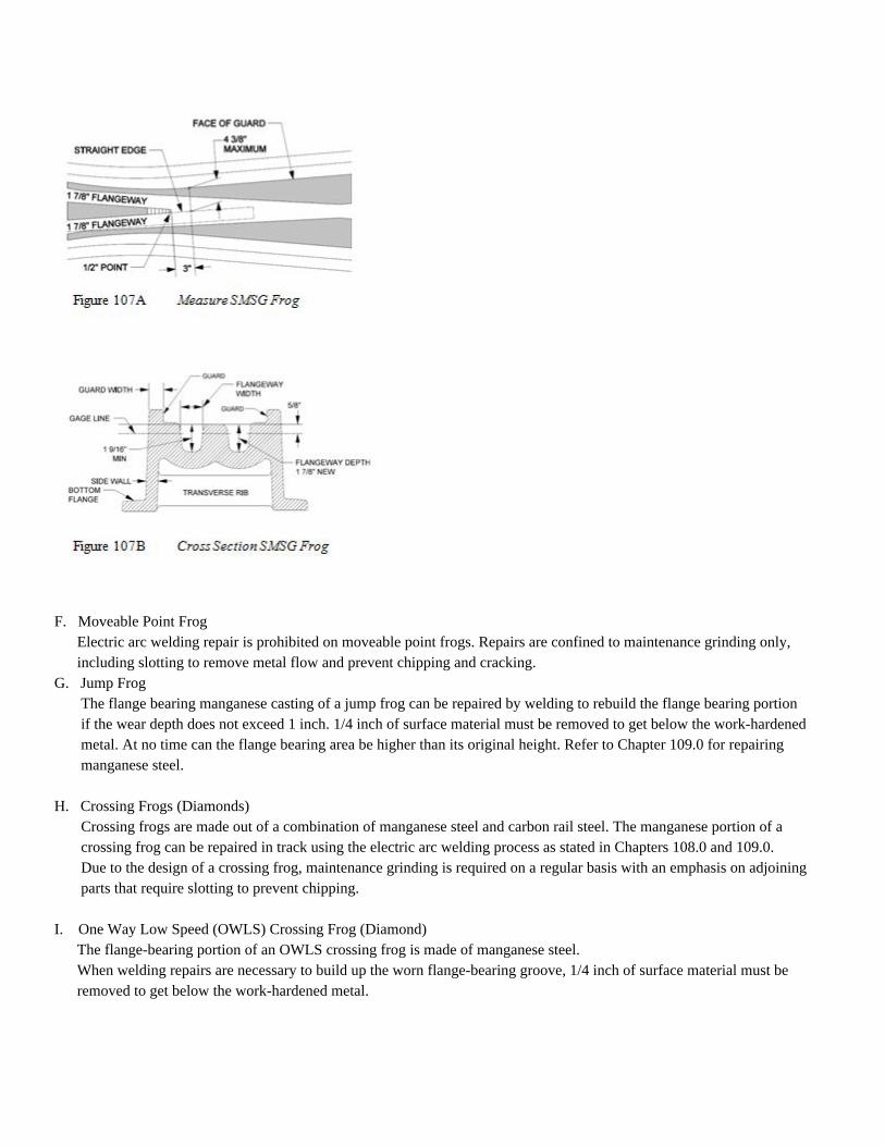
F. Moveable Point Frog Electric arc welding repair is prohibited on moveable point frogs. Repairs are confined to maintenance grinding only, including slotting to remove metal flow and prevent chipping and cracking.G. Jump Frog The flange bearing manganese casting of a jump frog can be repaired by welding to rebuild the flange bearing portion if the wear depth does not exceed 1 inch. 1/4 inch of surface material must be removed to get below the work-hardened metal. At no time can the flange bearing area be higher than its original height. Refer to Chapter 109.0 for repairing manganese steel.
H. Crossing Frogs (Diamonds) Crossing frogs are made out of a combination of manganese steel and carbon rail steel. The manganese portion of a crossing frog can be repaired in track using the electric arc welding process as stated in Chapters 108.0 and 109.0. Due to the design of a crossing frog, maintenance grinding is required on a regular basis with an emphasis on adjoining parts that require slotting to prevent chipping.
I. One Way Low Speed (OWLS) Crossing Frog (Diamond) The flange-bearing portion of an OWLS crossing frog is made of manganese steel. When welding repairs are necessary to build up the worn flange-bearing groove, 1/4 inch of surface material must be removed to get below the work-hardened metal.
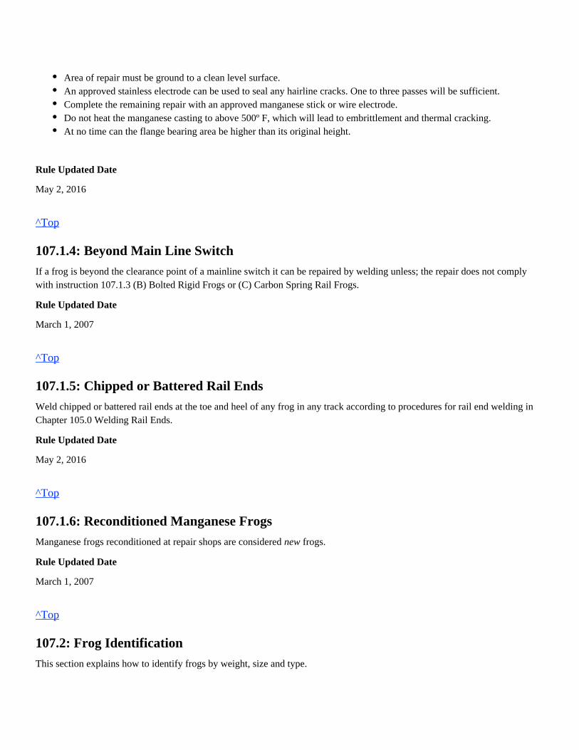
Rule Updated Date
May 2, 2016
^Top
107.1.4: Beyond Main Line Switch
If a frog is beyond the clearance point of a mainline switch it can be repaired by welding unless; the repair does not complywith instruction 107.1.3 (B) Bolted Rigid Frogs or (C) Carbon Spring Rail Frogs.
Rule Updated Date
March 1, 2007
^Top
107.1.5: Chipped or Battered Rail Ends
Weld chipped or battered rail ends at the toe and heel of any frog in any track according to procedures for rail end welding inChapter 105.0 Welding Rail Ends.
Rule Updated Date
May 2, 2016
^Top
107.1.6: Reconditioned Manganese Frogs
Manganese frogs reconditioned at repair shops are considered frogs.new
Rule Updated Date
March 1, 2007
^Top
107.2: Frog Identification
This section explains how to identify frogs by weight, size and type.
Area of repair must be ground to a clean level surface.An approved stainless electrode can be used to seal any hairline cracks. One to three passes will be sufficient.Complete the remaining repair with an approved manganese stick or wire electrode.Do not heat the manganese casting to above 500º F, which will lead to embrittlement and thermal cracking.At no time can the flange bearing area be higher than its original height.
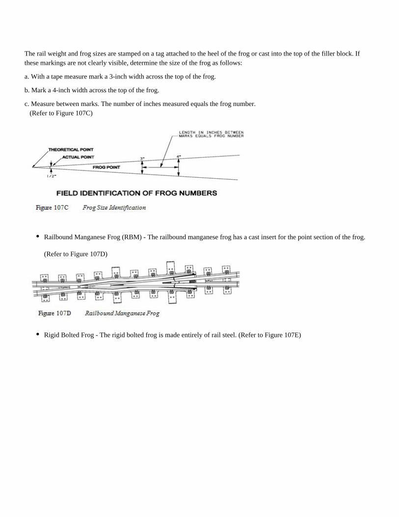
The rail weight and frog sizes are stamped on a tag attached to the heel of the frog or cast into the top of the filler block. Ifthese markings are not clearly visible, determine the size of the frog as follows:
a. With a tape measure mark a 3-inch width across the top of the frog.
b. Mark a 4-inch width across the top of the frog.
c. Measure between marks. The number of inches measured equals the frog number. (Refer to Figure 107C)
(Refer to Figure 107D)
Railbound Manganese Frog (RBM) - The railbound manganese frog has a cast insert for the point section of the frog.
Rigid Bolted Frog - The rigid bolted frog is made entirely of rail steel. (Refer to Figure 107E)
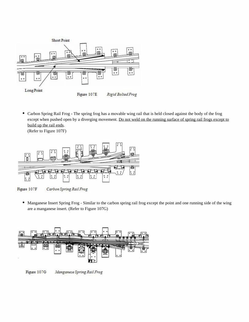
Carbon Spring Rail Frog - The spring frog has a movable wing rail that is held closed against the body of the frogexcept when pushed open by a diverging movement. Do not weld on the running surface of spring rail frogs except to
.build up the rail ends(Refer to Figure 107F)
Manganese Insert Spring Frog - Similar to the carbon spring rail frog except the point and one running side of the wingare a manganese insert. (Refer to Figure 107G)
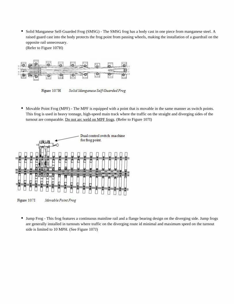
Solid Manganese Self-Guarded Frog (SMSG) - The SMSG frog has a body cast in one piece from manganese steel. Araised guard cast into the body protects the frog point from passing wheels, making the installation of a guardrail on theopposite rail unnecessary.(Refer to Figure 107H)
Movable Point Frog (MPF) - The MPF is equipped with a point that is movable in the same manner as switch points.This frog is used in heavy tonnage, high-speed main track where the traffic on the straight and diverging sides of theturnout are comparable. . (Refer to Figure 107I)Do not arc weld on MPF frogs
Jump Frog - This frog features a continuous mainline rail and a flange bearing design on the diverging side. Jump frogsare generally installed in turnouts where traffic on the diverging route id minimal and maximum speed on the turnoutside is limited to 10 MPH. (See Figure 107J)
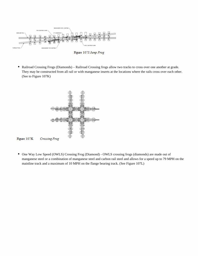
Railroad Crossing Frogs (Diamonds) – Railroad Crossing frogs allow two tracks to cross over one another at grade.They may be constructed from all rail or with manganese inserts at the locations where the rails cross over each other.(See to Figure 107K)
One Way Low Speed (OWLS) Crossing Frog (Diamond) - OWLS crossing frogs (diamonds) are made out ofmanganese steel or a combination of manganese steel and carbon rail steel and allows for a speed up to 79 MPH on themainline track and a maximum of 10 MPH on the flange bearing track. (See Figure 107L)
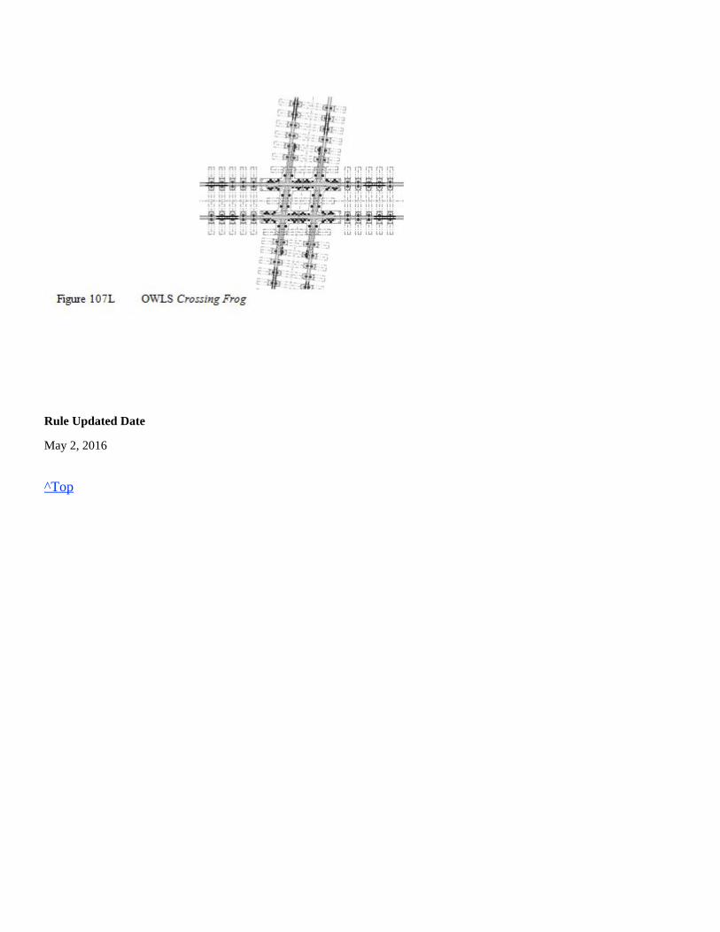
Rule Updated Date
May 2, 2016
^Top
Welding hood properly shaded with hard hat (unless using the approved non-hard hat PAPR welding hood), hearingprotection, safety glasses, leather welding gloves, welding jacket or welding sleeves, approved safety-toe boots andflame resistant clothing.
Hard hat, hearing protection, dual eye protection as follows:
leather welding gloves, welding jacket or welding sleeves, leather leggings, approved safety-toe boots and flameresistant clothing.
Hard hat, hearing protection, type of eye protection as follows:
work gloves, welding jacket or welding sleeves, leather leggings, approved safety-toe boots and flame resistantclothing.
Union Pacific Rules Track Welding Rules and Procedures
108.0: REPAIRING CARBON TURNOUT AND CROSSING (DIAMOND) FROGS
Chapter Introduction
The following instructions apply to welding carbon turnout (rigid bolted), crossing (diamond) frogs and allowableparts of all carbon steel spring rail frogs.
108.1: Personal Protective Equipment (PPE)
Task Required PPE
AbrasiveGrinding
See respiratory policy for respirator requirement.
Oxy-fuel/Fuel-gasHeating
See respiratory policy for respirator requirement.
ElectricArcWelding
See respiratory policy for respirator requirement.
108.1: Personal Protective Equipment (PPE)108.2: Preparing for Welding Carbon Steel108.2.2: Remove Defective Material108.2.1: Use Proper Stick and Wire Electrodes108.2.3: Preheating Carbon Rail Steel108.3: Welding Carbon Steel Turnout and Crossing Frogs108.3.1: Postheating Carbon Rail Steel Turnout and Crossing Frogs108.4: Finish Grinding108.5: Weld Spring Rail Frog Horn
1.
2.
Welding hood with clear lens or in grind mode with safety glasses, or
Wrap-around face shield with goggles or safety glasses (#5 shade must be worn),not
1.
2.
Wrap-around face shield with goggles or safety glasses. or(one has to be shade #5),
Mono-goggle XTR shade #5 with safety glasses can be used as an alternative,
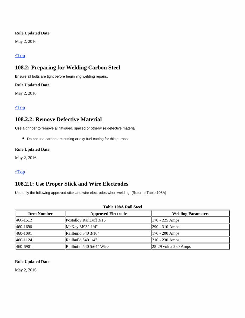
Rule Updated Date
May 2, 2016
^Top
108.2: Preparing for Welding Carbon Steel
Ensure all bolts are tight before beginning welding repairs.
Rule Updated Date
May 2, 2016
^Top
108.2.2: Remove Defective Material
Use a grinder to remove all fatigued, spalled or otherwise defective material.
Rule Updated Date
May 2, 2016
^Top
108.2.1: Use Proper Stick and Wire Electrodes
Use only the following approved stick and wire electrodes when welding. (Refer to Table 108A)
Table 108A Rail Steel
Item Number Approved Electrode Welding Parameters
460-1512 Postalloy RailTuff 3/16" 170 - 225 Amps
460-1690 McKay M932 1/4" 290 - 310 Amps
460-1091 Railbuild 540 3/16" 170 - 200 Amps
460-1124 Railbuild 540 1/4" 210 - 230 Amps
460-6901 Railbuild 540 5/64" Wire 28-29 volts/ 280 Amps
Rule Updated Date
May 2, 2016
Do not use carbon arc cutting or oxy-fuel cutting for this purpose.
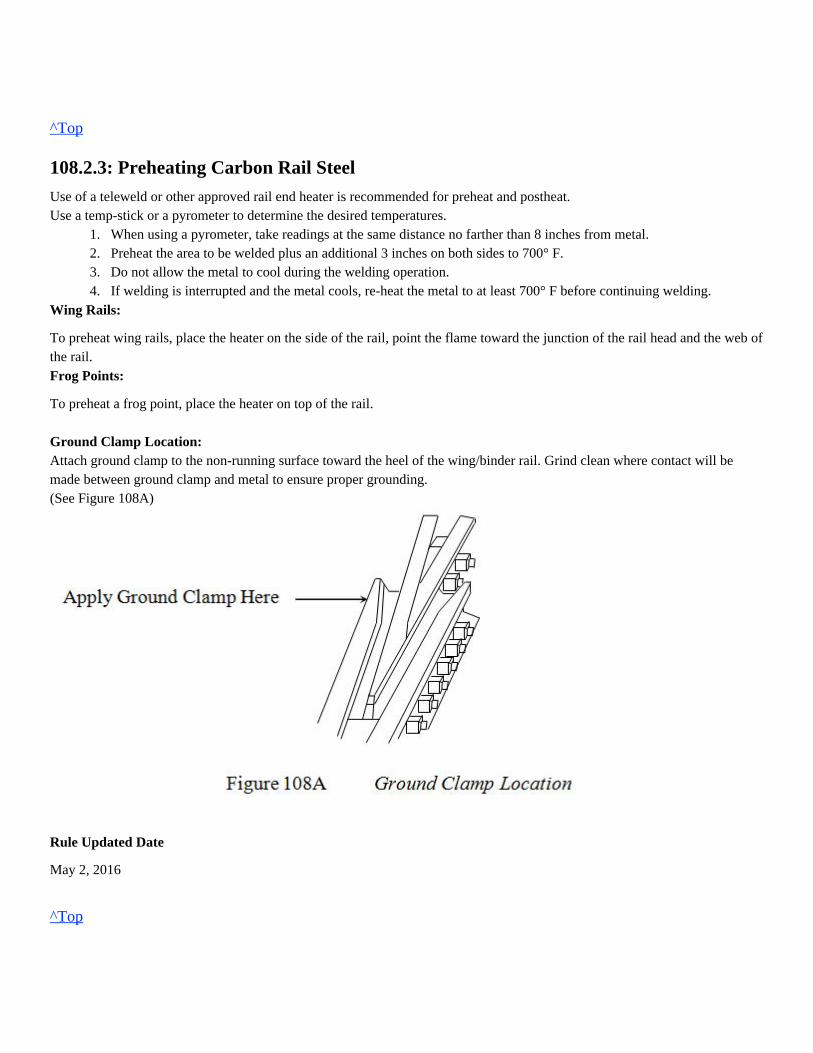
^Top
108.2.3: Preheating Carbon Rail Steel
Use of a teleweld or other approved rail end heater is recommended for preheat and postheat.Use a temp-stick or a pyrometer to determine the desired temperatures.
1. When using a pyrometer, take readings at the same distance no farther than 8 inches from metal.2. Preheat the area to be welded plus an additional 3 inches on both sides to 700° F.3. Do not allow the metal to cool during the welding operation.4. If welding is interrupted and the metal cools, re-heat the metal to at least 700° F before continuing welding.
Wing Rails:
To preheat wing rails, place the heater on the side of the rail, point the flame toward the junction of the rail head and the web ofthe rail.Frog Points:
To preheat a frog point, place the heater on top of the rail.
Ground Clamp Location:Attach ground clamp to the non-running surface toward the heel of the wing/binder rail. Grind clean where contact will bemade between ground clamp and metal to ensure proper grounding.(See Figure 108A)
Rule Updated Date
May 2, 2016
^Top
108.3: Welding Carbon Steel Turnout and Crossing Frogs
When welding turnout and crossing frogs:
1. Use electrodes as follows:
a. For heavy fill, use a 1/4-inch stick electrode, or wire.b. For shallow fill and for feathering out, use a 3/16-inch electrode.
2. Make the weld deposit in successive beads, 3/4 inch to 1 inch wide.3. Apply each bead parallel to the wing or point until the necessary buildup is obtained.4. Remove all slag with a chipping hammer before depositing the next layer of weld metal.
5. Peen each bead 2 to 3 times per inch with a 2 lb. Ball-Peen Hammer.
Rule Updated Date
May 2, 2016
^Top
108.3.1: Postheating Carbon Rail Steel Turnout and Crossing Frogs
Use a temp-stick or pyrometer to determine the desired temperatures. When using a pyrometer, take readings at the samedistance no farther than 8 inches from metal.Immediately after completing a weld repair, postheat the welded area plus an additional 3 inches on each side to 1,000° F.
Rule Updated Date
May 2, 2016
^Top
108.4: Finish Grinding
Grind all accessible areas of the turnout frog or crossing frog to the rail's proper running surface and contour as follows:1. Use a frog gauge to determine the correct radius and flangeway clearances.2. Grind all corners at the top of the turnout frog or crossing frog to a 3/8 – 5/8 inch radius.3. On turnout frogs, make sure the point at the tip is 1/4 inch lower than the adjacent wings and is sloped upward, so that thepoint and wings are level at a distance back from the point equal in inches to the number of the frog. (See Figure 108B) (Example)Length of slope is 7 inches for a #7 frog
Use of a needle scaler is prohibited.

Length of slope is 10 inches for a #10 frog
All mismatched, battered, or chipped rail ends must be repaired in accordance with rules and procedures in Chapter 105.0 Welding
Rail Ends.
Slot all adjoining rail to a depth of 3/16 inch using a 1/8 inch slotting wheel. (See Figure 108C)
Rule Updated Date
May 2, 2016
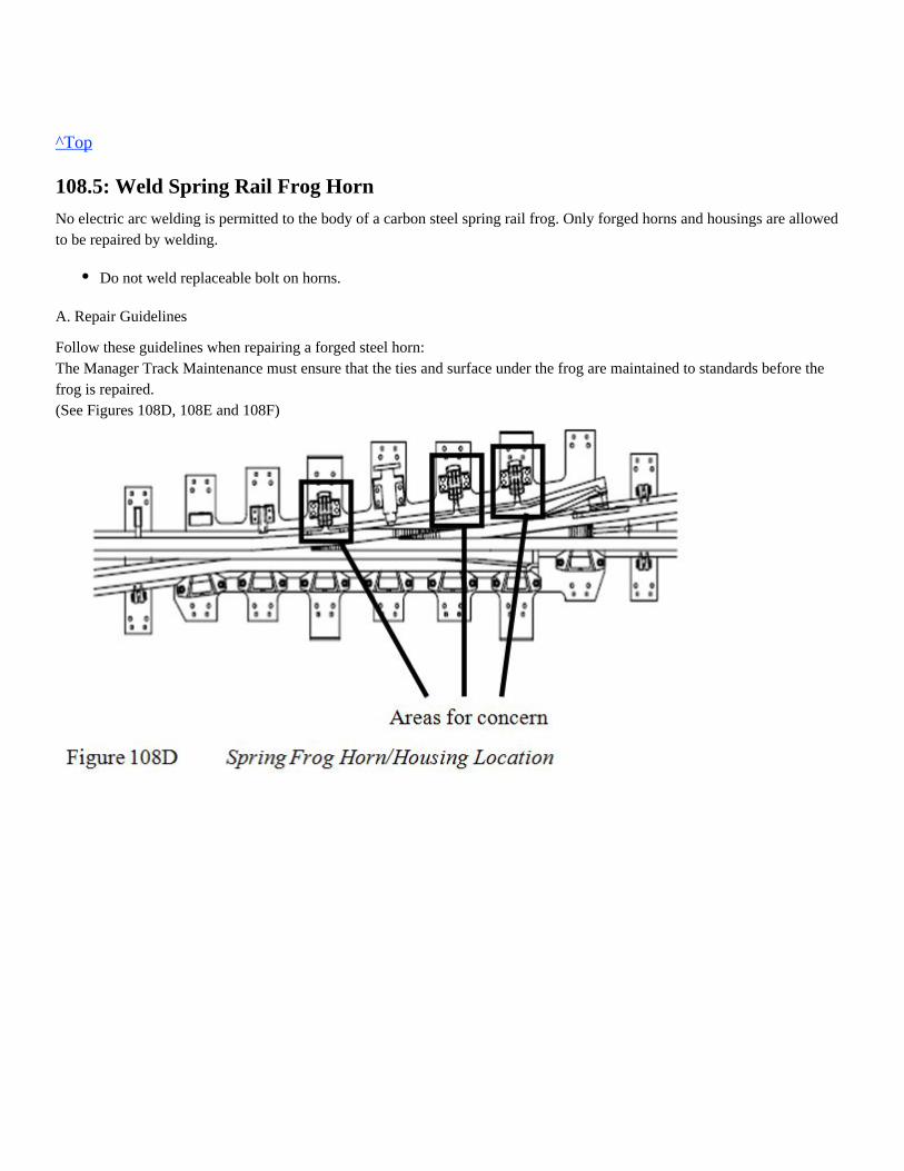
^Top
108.5: Weld Spring Rail Frog Horn
No electric arc welding is permitted to the body of a carbon steel spring rail frog. Only forged horns and housings are allowedto be repaired by welding.
A. Repair Guidelines
Follow these guidelines when repairing a forged steel horn:The Manager Track Maintenance must ensure that the ties and surface under the frog are maintained to standards before thefrog is repaired.(See Figures 108D, 108E and 108F)
Do not weld replaceable bolt on horns.
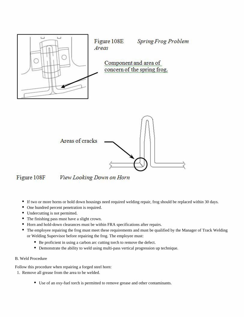
B. Weld Procedure
Follow this procedure when repairing a forged steel horn:
If two or more horns or hold down housings need required welding repair, frog should be replaced within 30 days.One hundred percent penetration is required.Undercutting is not permitted.The finishing pass must have a slight crown.Horn and hold-down clearances must be within FRA specifications after repairs.The employee repairing the frog must meet these requirements and must be qualified by the Manager of Track Weldingor Welding Supervisor before repairing the frog. The employee must:
Be proficient in using a carbon arc cutting torch to remove the defect.Demonstrate the ability to weld using multi-pass vertical progression up technique.
1. Remove all grease from the area to be welded.
Use of an oxy-fuel torch is permitted to remove grease and other contaminants.
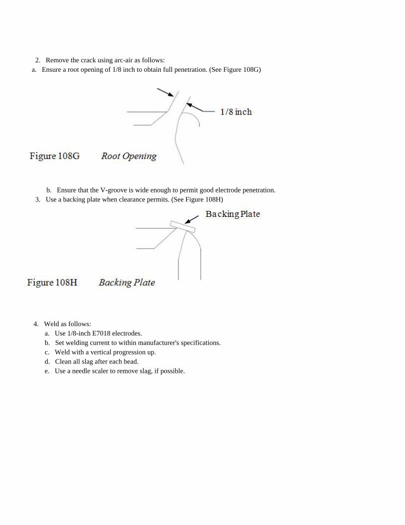
2. Remove the crack using arc-air as follows: a. Ensure a root opening of 1/8 inch to obtain full penetration. (See Figure 108G)
b. Ensure that the V-groove is wide enough to permit good electrode penetration.
3. Use a backing plate when clearance permits. (See Figure 108H)
4. Weld as follows:a. Use 1/8-inch E7018 electrodes.b. Set welding current to within manufacturer's specifications.c. Weld with a vertical progression up.d. Clean all slag after each bead.e. Use a needle scaler to remove slag, if possible.
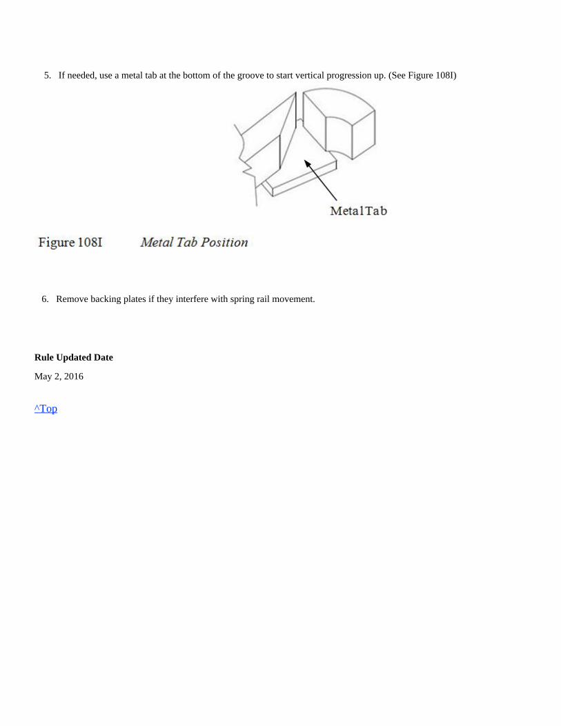
5. If needed, use a metal tab at the bottom of the groove to start vertical progression up. (See Figure 108I)
6. Remove backing plates if they interfere with spring rail movement.
Rule Updated Date
May 2, 2016
^Top
Union Pacific Rules Track Welding Rules and Procedures
109.0: REPAIRING MANGANESE TURNOUT AND CROSSING FROGS
Chapter Introduction
Scope:The following instructions apply to welding manganese turnout (RBM, insert spring rail) and crossing frogs (diamonds).Manganese steel exhibits the following characteristics:
Magnetic properties can be checked with a magnet in the flangeway of the frog.
Unlike most steels that soften when tempered at a relatively low temperature, manganese steel becomes brittle and magneticwhen heated above 500 F and will fracture easily.The outer portion of a manganese casting work-hardens to a depth of approximately 1/8 inch while the inner area remains ductile.Manganese steel can work-harden to more than twice its original hardness to approximately 535BHN.Until fully work-hardened, manganese steel remains ductile, and it deforms from its original shape when stressed.Good non work-hardened manganese steel is non-magnetic.Work-hardened manganese steel will have a slight magnetic attraction.
109.1: Personal Protective Equipment (PPE)109.2: Marking Weld Repairs109.3: Purpose of Repair109.4: Work-Hardening109.5: Mark and Remove Defective Material109.5.1: Power Source Setup (CAC)109.5.2: Ground Clamp Placement109.5.3: Remove Work Hardened Material109.5.4: Horizontal Cracks109.5.5: Vertical Cracks109.6: Repairing Manganese Steel Frogs109.6.1: Approved Stick and Wire Electrodes109.6.2: Manganese Buildup Procedures109.6.3: Weld Bead Length and Width109.6.4: Skip and Alternating Methods109.6.5: Maintain Temperature109.6.6: Welding Areas109.6.7: Removing Slag and Relieving Stress109.6.8: Train or Equipment Interruption109.6.9: Finish Grinding109.6.10: Slotting109.6.11: Use of Frog Gauges
Welding hood properly shaded with hard hat (unless using the approved non hard hat PAPR welding hood), hearingprotection, safety glasses, leather welding gloves, welding jacket or welding sleeves, approved safety-toe boots andflame resistant clothing.
Hard hat, hearing protection, dual eye protection as follows:
leather welding gloves, welding jacket or welding sleeves, leather leggings, approved safety-toe boots and flameresistant clothing.
Hard hat, hearing protection, type of eye protection as follows:
work gloves, welding jacket or welding sleeves, leather leggings, approved safety-toe boots and flame resistantclothing.
109.1: Personal Protective Equipment (PPE)
Task Required PPE
Abrasive
Grinding
See respiratory policy for respirator requirement.
Oxy-fuel
/Fuel-gas
Heating
See respiratory policy for respirator requirement.
Electric
Arc
Welding
See respiratory policy for respirator requirement and use of required fan.
Rule Updated Date
May 2, 2016
^Top
109.2: Marking Weld Repairs
109.6.12: Follow-up Grinding109.7: Repairs to Carbon Rail Steel Binder Rails109.7.1: Mark and Remove Defective Metal109.7.2: Preheat Carbon Rail Steel Binder Rail109.7.3: Welding Carbon Rail Steel Binder Rail109.7.4: Finish Grind Carbon Rail Steel Binder Rails109.7.5: Postheating Carbon Rail Steel Binder Rails109.8: Manganese Insert Spring Rail Frogs109.9: RBM Heel Leg Extension Rail (Carbon Rail Steel)109.9.1: RBM Frog Heel Leg Identification109.9.2: Instructions for Repair
1.
2.
Welding hood with clear lens or in grind mode with safety glasses, or
Wrap-around face shield with goggles or safety glasses (#5 shade must be worn),not
1.
2.
Wrap-around face shield with goggles or safety glasses. or(one has to be shade #5),
Mono-goggle XTR shade #5 with safety glasses can be used as an alternative,
After welding repairs are made to the manganese insert, place a mark on the base of the rail immediately next to the installation date
to indicate number of welding repairs. Use a white metal marker.
Rule Updated Date
May 2, 2016
^Top
109.3: Purpose of Repair
The purpose of repairing manganese frogs is to:
a) Flangeway depth must not be less than:
b) If the frog point is chipped, broken or worn more than 5/8 inch down and 6 inches back, operating speed will not be more than 10 MPH. (See Figure 109A)
c) If the tread portion of frog is worn down more than 3/8 inch below original contour, operating speed will not be more than 10 MPH. (See Figure 109A)d) Where frogs are designed as flange-bearing, flangeway depth may not be less than that shown for Class 1 if operated at Class 1 speeds.e) The flange-bearing casting of a One Way Low Speed (OWLS) crossing diamond or jump frog can be repaired by welding rebuild the flange bearing portion, if the wear depth does not exceed 1 inch. At no time can the flange bearing area be raised more than its original height.
Rule Updated Date
Repair broken or chipped areas.Restore worn surfaces to acceptable FRA standards.
1-3/8 inches for class 1 track.1-1/2 inches for classes 2 through 5 track.
After the first 6 inches, the point is considered the tread portion of frog.
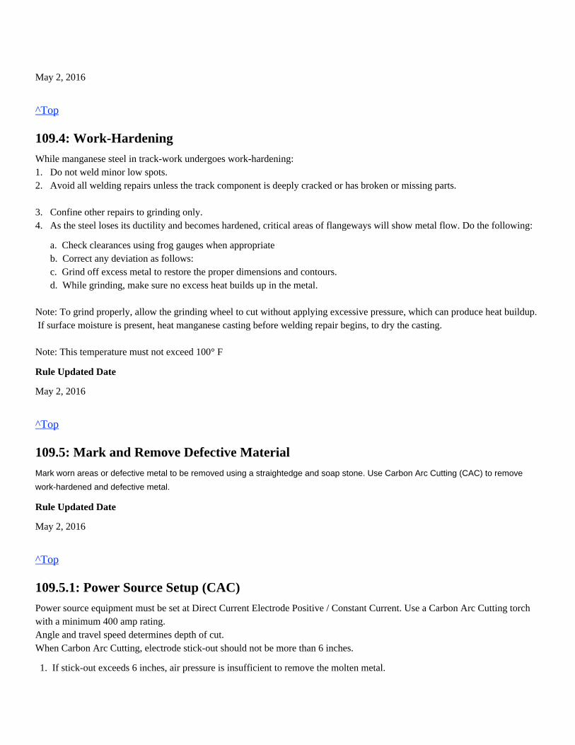
May 2, 2016
^Top
109.4: Work-Hardening
While manganese steel in track-work undergoes work-hardening:1. Do not weld minor low spots.2. Avoid all welding repairs unless the track component is deeply cracked or has broken or missing parts. 3. Confine other repairs to grinding only.4. As the steel loses its ductility and becomes hardened, critical areas of flangeways will show metal flow. Do the following:
a. Check clearances using frog gauges when appropriate b. Correct any deviation as follows: c. Grind off excess metal to restore the proper dimensions and contours. d. While grinding, make sure no excess heat builds up in the metal.
Note: To grind properly, allow the grinding wheel to cut without applying excessive pressure, which can produce heat buildup. If surface moisture is present, heat manganese casting before welding repair begins, to dry the casting.
Note: This temperature must not exceed 100° F
Rule Updated Date
May 2, 2016
^Top
109.5: Mark and Remove Defective Material
Mark worn areas or defective metal to be removed using a straightedge and soap stone. Use Carbon Arc Cutting (CAC) to remove
work-hardened and defective metal.
Rule Updated Date
May 2, 2016
^Top
109.5.1: Power Source Setup (CAC)
Power source equipment must be set at Direct Current Electrode Positive / Constant Current. Use a Carbon Arc Cutting torchwith a minimum 400 amp rating.Angle and travel speed determines depth of cut.When Carbon Arc Cutting, electrode stick-out should not be more than 6 inches.
1. If stick-out exceeds 6 inches, air pressure is insufficient to remove the molten metal.
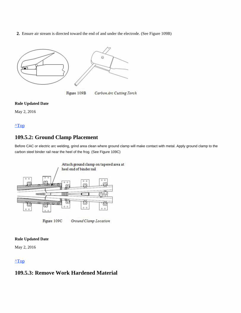
Rule Updated Date
May 2, 2016
^Top
109.5.2: Ground Clamp Placement
Before CAC or electric arc welding, grind area clean where ground clamp will make contact with metal. Apply ground clamp to the
carbon steel binder rail near the heel of the frog. (See Figure 109C)
Rule Updated Date
May 2, 2016
^Top
109.5.3: Remove Work Hardened Material
2. Ensure air stream is directed toward the end of and under the electrode. (See Figure 109B)
Use CAC to remove work-hardened material.
Rule Updated Date
May 2, 2016
^Top
109.5.4: Horizontal Cracks
Use CAC to remove horizontal cracks.
Rule Updated Date
May 2, 2016
^Top
109.5.5: Vertical Cracks
Use CAC to remove material at a vertical crack.
Remove 1/4 inch of metal to get below work-hardened zone.Do not allow the temperature of the manganese casting to exceed 500º F, which will result in embrittlement and thermalcracking.After CAC, grind area to a clean level surface.
Remove all horizontal cracks and taper area at ends to accommodate grinding wheels.To properly remove defective metal, remove metal at each end of the crack and work back toward damaged metal andcrack. Cutting from both ends of a horizontal crack may allow for the removal of a single piece of metal. (See Figure109D)
After removing metal piece, use CAC or grinding to remove at least 1/4 inch of work-hardened surface metal.Grind area to a clean level surface.
Identify vertical crack.
Rule Updated Date
May 2, 2016
^Top
109.6: Repairing Manganese Steel Frogs
Rule Updated Date
May 2, 2016
Remove entire vertical crack if possible, without burning through frog casting.For cracks in frog flangeway including longitudinal cracks in the bottom of the flangeway, do not exceed 1/2 inch depthin metal removal.On frog wing rails and frog point, remove metal in the shape of a 'U' groove type pattern. (See Figure 109E)Grind repair area to a clean surface.Use an approved stainless stick electrode designed to seal vertical cracks that be fully removed.cannot
Use no more than three passes over crack.(See Figure 109F)
Complete the buildup using approved manganese welding product.Do not allow the temperature of the manganese casting to exceed 500º F, which will result in embrittlement and thermalcracking.
^Top
109.6.1: Approved Stick and Wire Electrodes
(Refer to Table 109A and Table 109B)
Table 109A Stainless Steel Type
Item Number Approved Electrode Welding Parameters
460-4060 Postalloy 1/8" 120 Amps
460-1043 Postalloy 5/32" 140 Amps
Table 109B Manganese Steel
Item Number Approved Electrode Welding Parameters
460-1042 Frogbuild 3/16" 180-200 Amp
460-1047 Frogbuild 7/32" 200-220 Amps
460-1100 FrogMang 3/16" 175-215 Amps
460-1101 FrogMang 1/4" 235-280 Amps
460-6915 Frogbuild 575 5/64" Wire 28 - 29 Volts/ 280 Amps
460-6905 Lincoln FrogMang 5/64" Wire 28 - 29 Volts/ 280 Amps
460-1036 Postalloy FrogTuff 5/64" Wire 28 - 29 Volts/ 280 Amps
Note: Manganese stick electrodes are a drag type electrode.
(Maintain contact with the component while welding)
Rule Updated Date
May 2, 2016
^Top
109.6.2: Manganese Buildup Procedures
When repairing manganese castings by welding, use the following instructions:
Rule Updated Date
May 2, 2016
Maintain a 10º to 30º trailing electrode angle from vertical axis while welding.- Drag the molten steel puddle, do not push it.Do not start and stop beads at the same place, which creates stress lines – overlap bead start and stops.Use proper amperage and travel speed to prevent overheating.
^Top
109.6.3: Weld Bead Length and Width
To maintain proper weld bead characteristics and low heat input.
1. Bead length must not exceed 9 inches with stick electrodes. 2. Bead length must not exceed 12 inches with wire electrodes. 3. Bead width must not exceed 5/8 inch maximum.
Rule Updated Date
May 2, 2016
^Top
109.6.4: Skip and Alternating Methods
Skip Method: To help prevent frogs from overheating when repairing one portion of the frog, weld a bead of proper length,skip 6 inches, then weld another bead of proper length.
Alternating Method: When repairing more than one part of the frog, alternate from point to wings to avoid over-heating. Toevenly support the weight of trains, build up frog point and wing rails together to maintain even height.
Rule Updated Date
May 2, 2016
^Top
109.6.5: Maintain Temperature
Manganese steel changes metallurgical properties at temperatures above 500° F. It becomes brittle and can fracture easily.
Note: If using a non-contact pyrometer, always check at a distance not exceeding 8 inches.
If temperature of manganese casting approaches 500º F., stop all welding and cool steel with air flow.
Rule Updated Date
May 2, 2016
When welding on manganese steel, keep temperature of the base metal below 500° F.Periodically check temperature 1/2 inch from deposited metal by using either the appropriate temp-stick or pyrometer.
Air is the only approved method for cooling manganese steel.
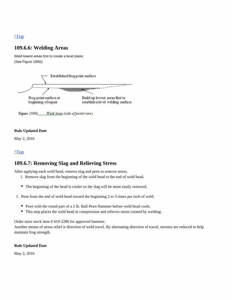
^Top
109.6.6: Welding Areas
Weld lowest areas first to create a level plane.
(See Figure 109G)
Rule Updated Date
May 2, 2016
^Top
109.6.7: Removing Slag and Relieving Stress
After applying each weld bead, remove slag and peen to remove stress. 1. Remove slag from the beginning of the weld bead to the end of weld bead.
Order store stock item # 410-2286 for approved hammer.Another means of stress relief is direction of weld travel. By alternating direction of travel, stresses are reduced to helpmaintain frog strength.
Rule Updated Date
May 2, 2016
The beginning of the bead is cooler so the slag will be more easily removed.
1. Peen from the end of weld bead toward the beginning 2 to 3 times per inch of weld.
Peen with the round part of a 2 lb. Ball-Peen Hammer before weld bead cools.This step places the weld bead in compression and relieves stress created by welding.
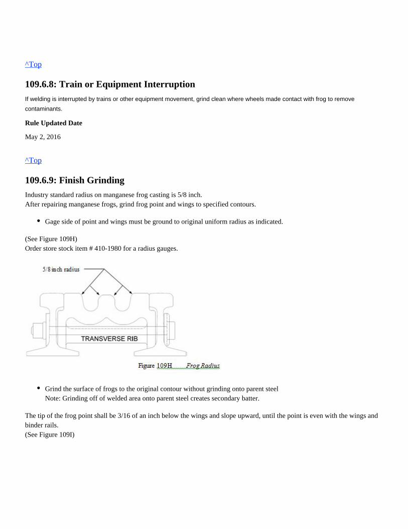
^Top
109.6.8: Train or Equipment Interruption
If welding is interrupted by trains or other equipment movement, grind clean where wheels made contact with frog to remove
contaminants.
Rule Updated Date
May 2, 2016
^Top
109.6.9: Finish Grinding
Industry standard radius on manganese frog casting is 5/8 inch.After repairing manganese frogs, grind frog point and wings to specified contours.
(See Figure 109H)Order store stock item # 410-1980 for a radius gauges.
The tip of the frog point shall be 3/16 of an inch below the wings and slope upward, until the point is even with the wings andbinder rails.(See Figure 109I)
Gage side of point and wings must be ground to original uniform radius as indicated.
Grind the surface of frogs to the original contour without grinding onto parent steelNote: Grinding off of welded area onto parent steel creates secondary batter.
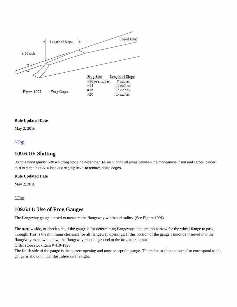
Rule Updated Date
May 2, 2016
^Top
109.6.10: Slotting
Using a hand grinder with a slotting stone no wider than 1/8 inch, grind all areas between the manganese insert and carbon binder
rails to a depth of 3/16 inch and slightly bevel to remove sharp edges.
Rule Updated Date
May 2, 2016
^Top
109.6.11: Use of Frog Gauges
The flangeway gauge is used to measure the flangeway width and radius. (See Figure 109J) The narrow side, or check side of the gauge is for determining flangeways that are too narrow for the wheel flange to passthrough. This is the minimum clearance for all flangeway openings. If this portion of the gauge cannot be inserted into theflangeway as shown below, the flangeway must be ground to the original contour.Order store stock item # 410-1990The finish side of the gauge is the correct opening and must accept the gauge. The radius at the top must also correspond to thegauge as shown in the illustration on the right.
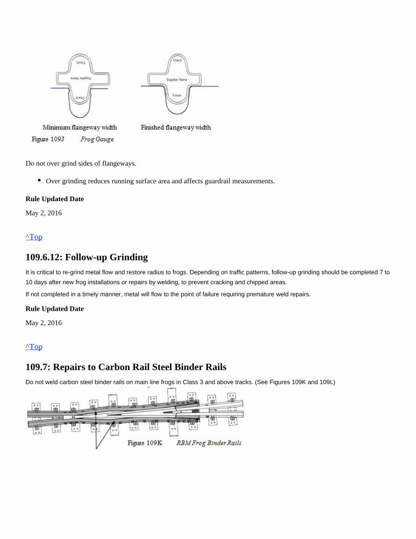
Do not over grind sides of flangeways.
Rule Updated Date
May 2, 2016
^Top
109.6.12: Follow-up Grinding
It is critical to re-grind metal flow and restore radius to frogs. Depending on traffic patterns, follow-up grinding should be completed 7 to
10 days after new frog installations or repairs by welding, to prevent cracking and chipped areas.
If not completed in a timely manner, metal will flow to the point of failure requiring premature weld repairs.
Rule Updated Date
May 2, 2016
^Top
109.7: Repairs to Carbon Rail Steel Binder Rails
Do not weld carbon steel binder rails on main line frogs in Class 3 and above tracks. (See Figures 109K and 109L)
Over grinding reduces running surface area and affects guardrail measurements.
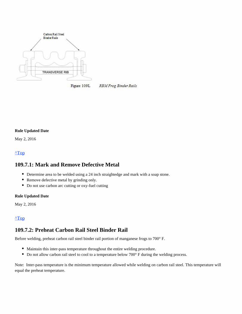
Rule Updated Date
May 2, 2016
^Top
109.7.1: Mark and Remove Defective Metal
Rule Updated Date
May 2, 2016
^Top
109.7.2: Preheat Carbon Rail Steel Binder Rail
Before welding, preheat carbon rail steel binder rail portion of manganese frogs to 700° F.
Note: Inter-pass temperature is the minimum temperature allowed while welding on carbon rail steel. This temperature willequal the preheat temperature.
Determine area to be welded using a 24 inch straightedge and mark with a soap stone.Remove defective metal by grinding only.Do not use carbon arc cutting or oxy-fuel cutting
Maintain this inter-pass temperature throughout the entire welding procedure.Do not allow carbon rail steel to cool to a temperature below 700° F during the welding process.
If the welding repair is interrupted and carbon rail steel binder rail cools below minimum inter-pass temperature, re-heat to aminimum of 700° F before resuming welding repairs.
Rule Updated Date
May 2, 2016
^Top
109.7.3: Welding Carbon Rail Steel Binder Rail
Do not begin or end weld beads over a bolt hole.
Approved stick and wire electrodes for welding rail steels must be used with a weld bead width of 3/4 inch to 1 inch.
Rule Updated Date
May 2, 2016
^Top
109.7.4: Finish Grind Carbon Rail Steel Binder Rails
When welding is completed, grind binder rails to their existing contour.
Rule Updated Date
May 2, 2016
^Top
109.7.5: Postheating Carbon Rail Steel Binder Rails
Rule Updated Date
May 2, 2016
Beginning or ending weld beads over a bolt hole increases the chance of rail breaking due to stresses caused by weldingand the wheel transition from binder rail to manganese wing rail.
Remove slag from each weld bead before relieving stress by peening. Do not use a needle scaler for this purpose.Strike weld bead 2 to 3 times per inch of weld using a 2 lb. Ball-Peen Hammer to relieve stress.
Postheating the carbon steel binder rails is prohibited.This will increase the risk of overheating the adjoining manganese steel casting causing it to become brittle and createthermal cracks.
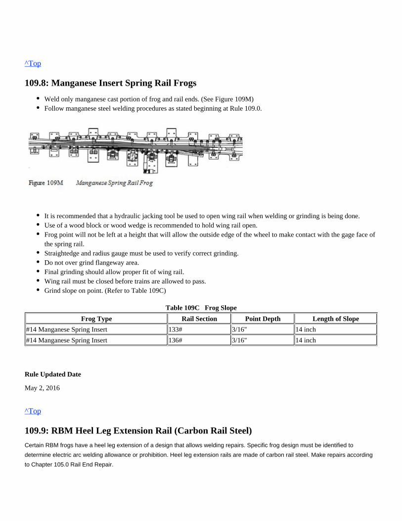
^Top
109.8: Manganese Insert Spring Rail Frogs
Table 109C Frog Slope
Frog Type Rail Section Point Depth Length of Slope
#14 Manganese Spring Insert 133# 3/16" 14 inch
#14 Manganese Spring Insert 136# 3/16" 14 inch
Rule Updated Date
May 2, 2016
^Top
109.9: RBM Heel Leg Extension Rail (Carbon Rail Steel)
Certain RBM frogs have a heel leg extension of a design that allows welding repairs. Specific frog design must be identified to
determine electric arc welding allowance or prohibition. Heel leg extension rails are made of carbon rail steel. Make repairs according
to Chapter 105.0 Rail End Repair.
Weld only manganese cast portion of frog and rail ends. (See Figure 109M)Follow manganese steel welding procedures as stated beginning at Rule 109.0.
It is recommended that a hydraulic jacking tool be used to open wing rail when welding or grinding is being done.Use of a wood block or wood wedge is recommended to hold wing rail open.Frog point will not be left at a height that will allow the outside edge of the wheel to make contact with the gage face ofthe spring rail.Straightedge and radius gauge must be used to verify correct grinding.Do not over grind flangeway area.Final grinding should allow proper fit of wing rail.Wing rail must be closed before trains are allowed to pass.Grind slope on point. (Refer to Table 109C)
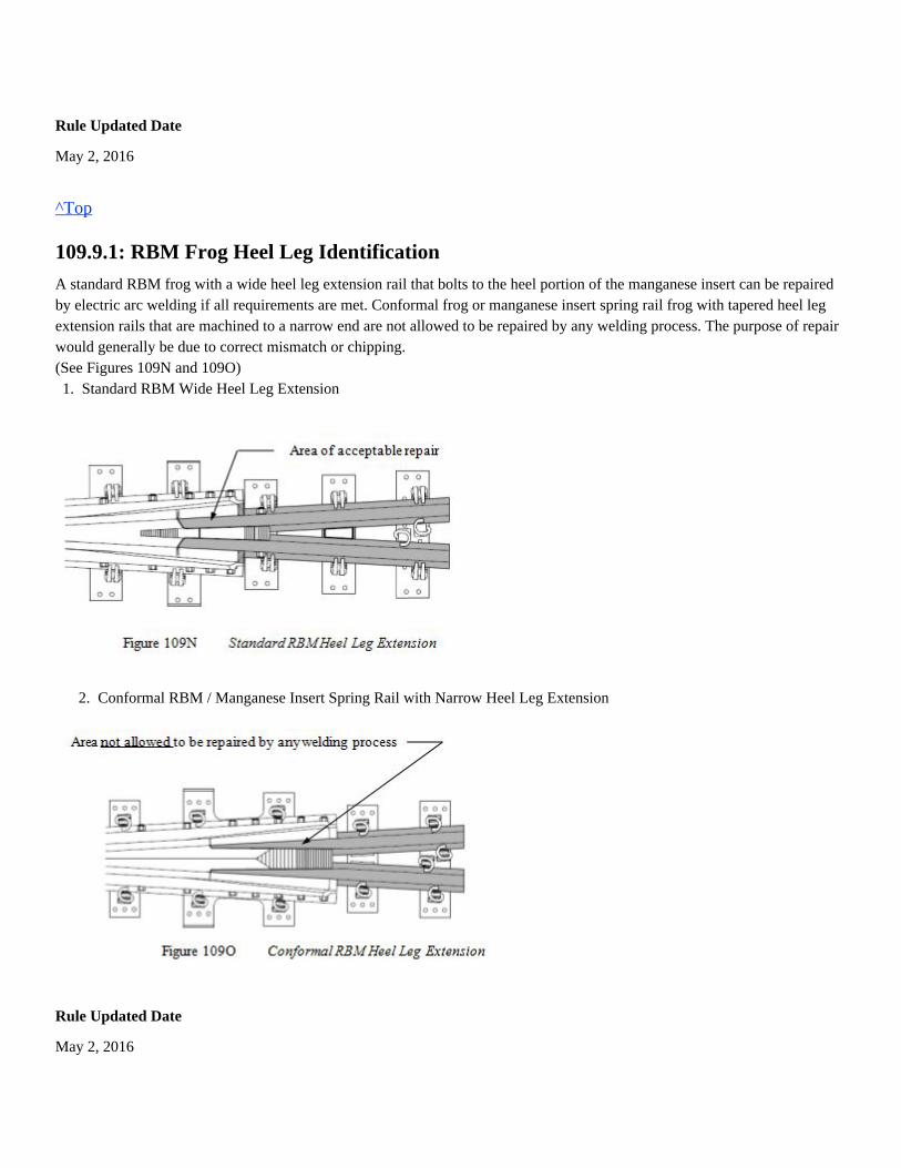
Rule Updated Date
May 2, 2016
^Top
109.9.1: RBM Frog Heel Leg Identification
A standard RBM frog with a wide heel leg extension rail that bolts to the heel portion of the manganese insert can be repairedby electric arc welding if all requirements are met. Conformal frog or manganese insert spring rail frog with tapered heel legextension rails that are machined to a narrow end are not allowed to be repaired by any welding process. The purpose of repairwould generally be due to correct mismatch or chipping. (See Figures 109N and 109O)
2. Conformal RBM / Manganese Insert Spring Rail with Narrow Heel Leg Extension
Rule Updated Date
May 2, 2016
1. Standard RBM Wide Heel Leg Extension
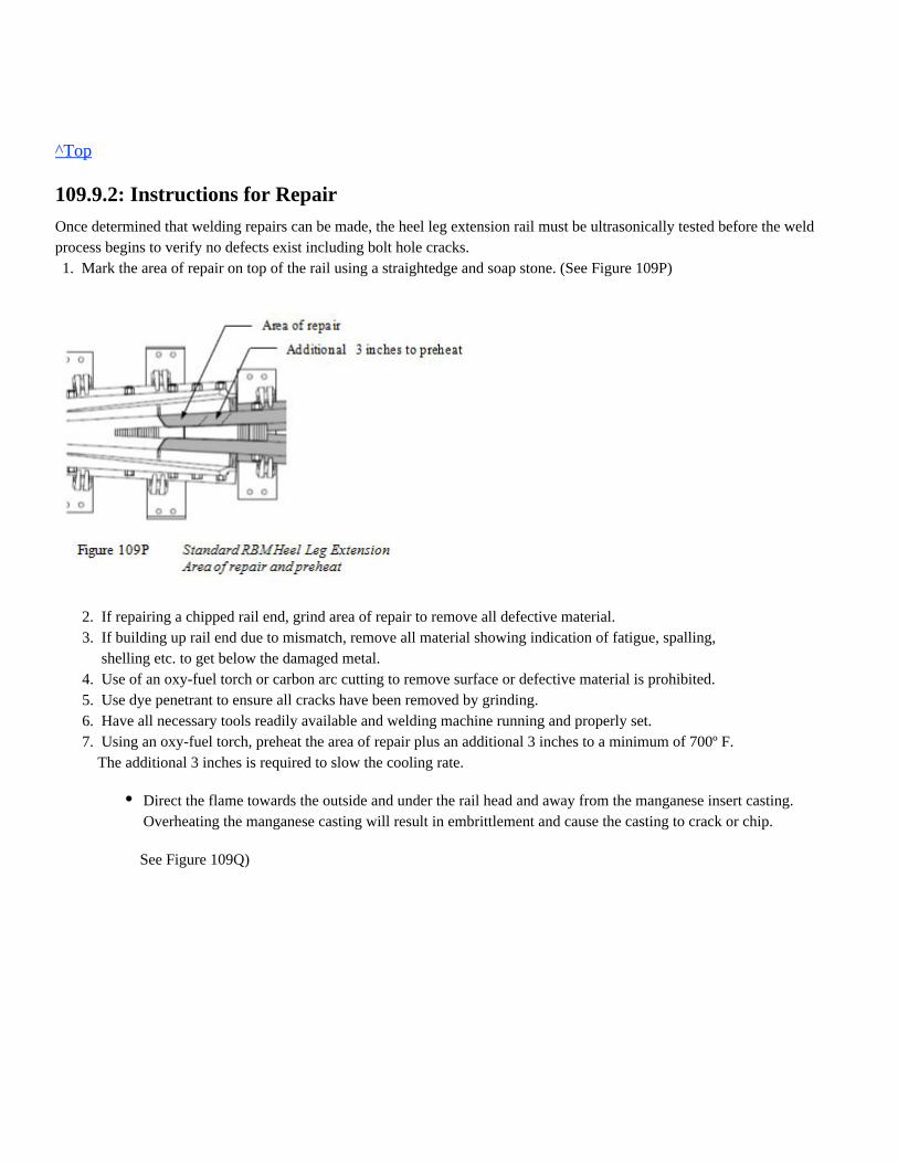
^Top
109.9.2: Instructions for Repair
Once determined that welding repairs can be made, the heel leg extension rail must be ultrasonically tested before the weldprocess begins to verify no defects exist including bolt hole cracks.
2. If repairing a chipped rail end, grind area of repair to remove all defective material. 3. If building up rail end due to mismatch, remove all material showing indication of fatigue, spalling, shelling etc. to get below the damaged metal. 4. Use of an oxy-fuel torch or carbon arc cutting to remove surface or defective material is prohibited. 5. Use dye penetrant to ensure all cracks have been removed by grinding. 6. Have all necessary tools readily available and welding machine running and properly set. 7. Using an oxy-fuel torch, preheat the area of repair plus an additional 3 inches to a minimum of 700º F. The additional 3 inches is required to slow the cooling rate.
See Figure 109Q)
1. Mark the area of repair on top of the rail using a straightedge and soap stone. (See Figure 109P)
Direct the flame towards the outside and under the rail head and away from the manganese insert casting.Overheating the manganese casting will result in embrittlement and cause the casting to crack or chip.
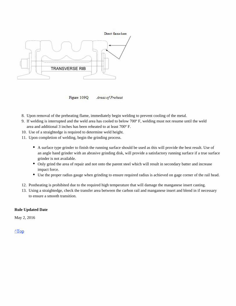
8. Upon removal of the preheating flame, immediately begin welding to prevent cooling of the metal. 9. If welding is interrupted and the weld area has cooled to below 700º F, welding must not resume until the weld area and additional 3 inches has been reheated to at least 700º F. 10. Use of a straightedge is required to determine weld height. 11. Upon completion of welding, begin the grinding process.
12. Postheating is prohibited due to the required high temperature that will damage the manganese insert casting. 13. Using a straightedge, check the transfer area between the carbon rail and manganese insert and blend in if necessary to ensure a smooth transition.
Rule Updated Date
May 2, 2016
^Top
A surface type grinder to finish the running surface should be used as this will provide the best result. Use ofan angle hand grinder with an abrasive grinding disk, will provide a satisfactory running surface if a true surfacegrinder is not available.Only grind the area of repair and not onto the parent steel which will result in secondary batter and increaseimpact force.Use the proper radius gauge when grinding to ensure required radius is achieved on gage corner of the rail head.
Union Pacific Rules Track Welding Rules and Procedures
110.0: THERMITE WELDS: RAILTECH-BOUTET
Chapter Introduction
Following proper welding and safety procedures is essential to the installation of a quality thermite weld and the continued safe
operation of the Union Pacific Railroad.
110.1: Personal Protective Equipment (PPE)110.2: Safety110.3: General110.3.1: Replacement Rail110.4: Weather Restrictions110.5: Identify Rail110.5.1: Identify Rail Type (Alloy or Standard)110.5.2: Determine Weld Location110.5.3: Compromise Welds110.6: Compromise/Transition Rail110.7: Speed Restrictions - Alloy Rail110.8: Eliminate Bolt Holes110.9: Reference Marks110.10: Remove Defects110.11: Torch Cut Rail110.12: Rail Puller110.13: Clean Rail Ends110.14: Rail End Gap - Standard (1-inch) and Wide Gap Weld (WGW)110.15: Alignment System110.16: Create Crown - Standard and Wide Gap Weld110.17: Rail Alignment (Straight and Compromise)110.18: Molds, Base Plate and Packing110.18.1: Molds and Base Plate110.18.2: Packing110.19: Position Slag Basin110.20: Preheating Procedures110.20.1: Use of Oxy-Propane Equipment110.20.2: Start the Preheat Process (Refer to Table 110B)110.20.3: Monitor Preheating Process110.20.4: Railtech Propane/Compressed Air Rail Preheater (Model 03800B)
Hard hat, hearing protection, dual eye protection as follows:
leather welding gloves, welding jacket or welding sleeves, leather leggings, approved safety-toeboots and flame resistant clothing.
Oxy-fuel/ Fuel-gas use:
Hard hat, hearing protection, type of eye protection as follows:
work gloves, welding jacket or welding sleeves, leather leggings, approved safety-toe boots andflame resistant clothing.
110.1: Personal Protective Equipment (PPE)
Task Required PPE
Abrasive grinding and cutting
rail
See respiratory policy for respirator requirement.
110.21: Crucible110.22: Igniting and Pouring110.23: Minimum Take Down Times110.24: Remove Excess Mold110.25: Rough Grinding110.26: Finish Grinding110.27: Weld Tolerance Specifications110.28: Identify Weld110.30: Clean Up110.29: Thermite Weld Quality Audit110.32: Thermite Head Wash Weld110.32.1: Rail Preparation110.31: Welders Log Booklet110.32.2: Dye Penetrant Testing110.32.3: Torch Height110.32.4: Molds and Clamp110.32.5: Preheating (Oxy-fuel Torch)110.32.6: Preheating (Forced Air/Propane Torch)110.32.7: Take Down Times110.32.8: Protect Weld from Cooling110.32.9: Grinding110.32.10: Clean Up110.32.11: Required Molds and Equipment
1.
2.
Welding hood with clear lens or in grind mode with safety glasses, or
Wrap-around face shield with goggles or safety glasses (#5 shade must be worn),not
cutting railwarming railremoving grease andmill scale
1.
2.
Wrap-around face shield with goggles or safety glasses. or(one has to be shade #5),
Mono-goggle XTR shade #5 with safety glasses can be used as an alternative,
Hard hat, hearing protection, type of eye protection as follows:
See respiratory policy for respirator requirement.
Removing weld mold material
and risers
work gloves, welding jacket or welding sleeves, approved safety-toe boots, and flame resistantclothing.
Packing Molds Hard hat and gloves are required.
Rule Updated Date
May 2, 2016
^Top
110.2: Safety
The presence of moisture in the thermite portion or in the crucible can lead to the rapid buildup and uncontrolled release ofsteam when the thermite reaction occurs.
Rule Updated Date
May 2, 2016
^Top
110.3: General
The instructions below must be followed when installing a thermite weld.These instructions apply to installing Railtech thermite welds.Only Railtech materials (molds, portions, pre-mix packing sand and crucibles) are to be used when installing Railtech welds.Individual thermite welds are the responsibility of the welder who performs the preheating of the rail ends.All thermite welds must have reference marks indicating the original amount of rail between marks.Do not use a wet crucible, molds or thermite oxide charge to make a weld.
observing thermitepreheat
1.
2.
Wrap-around face shield with goggles or safety glasses or,
Mono-goggle XTR with safety glasses can be used as an alternative,
This may cause ejection of the molten metal from the crucible. Therefore, the thermite portion, crucible, and moldsmust be dry and moisture must not be allowed to enter the system before or during the welding process.Moisture will also cause the weld to be defective.
If moisture enters the crucible, molds or charge, or is suspected of being present in one of them, discard the damageditem. Before discarding charges or igniters, contact the local Manager Environmental Field Operations for instructions onproper disposal.
It is critical to the success of the weld that no movement, shock, or vibration occurs in the rail during the solidification processof the molten steel.Recommended shelf life for weld kits is three years. All weld kits must be stored in a dry location, stacked no more than threekits high.When using mold kits:
Compromise welds (different rail base widths) must not be installed in class 4 and above main tracks:
It is not recommended to thermite weld a non-curve worn rail to a section of curve worn rail, especially on the high side of acurve.
Proper location of a thermite weld is the center of the crib.Apply reinforcing weld-mate straps to thermite welds only under the following circumstances in any FRA class of track:
Rule Updated Date
May 2, 2016
^Top
110.3.1: Replacement Rail
All replacement rails must be UT tested or certified in accordance with the Engineering Track Maintenance Field Handbook.
Replacement rail used for maintenance welding must be at least 15 feet in length.
Use a compromise/transition rail on 6 inch base rail when rail end mismatch exceeds 1/4 inch on main track and sidings.
Torch cut rail ends must have at least 2 inches removed with a rail saw.If a rail end is ground down to eliminate mismatch, ground portion must be cut out or replacement rail installed on main trackprior to thermite welding. Rail ends must be square to get proper crown.
Inspect crucibles for loose sand, cracks and loose thimbles.Molds that are broken with pieces missing should not be used.Use standard molds for rail end mismatch up to 1/8 inch.Use new to worn molds if rail ends are mismatched between 1/8 inch and 1/4 inch.
On subdivisions where regularly scheduled passenger trains operate.On subdivisions in excess of 40 MGT.
The maximum difference in curve worn rail head width should not exceed 1/8 inch on the gage side of the rail head.This measurement for curve wear should be taken at the top of the rail head.Excessive mismatch must be tapered with a grinder to provide a smooth transition.
Compromise thermite welds that are between rails of different sections (rail base widths).Thermite welds that involve alloy rail (one or both rails).
Vertical height difference must not exceed 1/4 inch.
Rule Updated Date
May 2, 2016
^Top
110.4: Weather Restrictions
When severe temperatures and weather conditions are present, observe the following welding restrictions: 1. Do not make thermite welds on alloy rail when the rail temperature is below 32° F. 2. Do not make any other welds when the rail temperature falls below 5° F. 3. When rail temperature is at or below 40º F, or in windy conditions, thermite weld must be covered immediately aftershearing with a cooling cap or welding blanket until the weld cools to below 700º F., to prevent weld from cooling too quickly.
4. During rain, sleet, snow or mist;light
Take the following measures to prevent moisture from entering the mold, crucible or welding charge:
5. Before applying molds, use a rail thermometer or pyrometer to check the rail temperature. If the rail temperature isbelow 35° F, warm the rails as follows:
Rule Updated Date
May 2, 2016
^Top
110.5: Identify Rail
Rule Updated Date
Do not begin the welding process unless properly protected from wet weather.If the thermite weld process is already in progress, protect the weld from excessive moisture or stop the weldingoperation.
Use of a welding tent with a solid top is allowed to prevent moisture from entering the molds and crucible.Use of an umbrella is allowed from entering molds and crucible.only if moisture can be entirely preventedEnsure that rain, sleet, snow, or mist does not cool the rail placing the weld in tension as the rail contracts.Use a rail puller, when conditions require, to prevent rail movement.During takedown, all welding mold remnants and slag must be placed to eliminate all hazards including slip, tripand fall hazards.
Heat 30 inches to 36 inches from the end of each rail.Raise the rail temperature to between 90° F and 110° F.(This is to add supplemental heat and remove surface condensation)
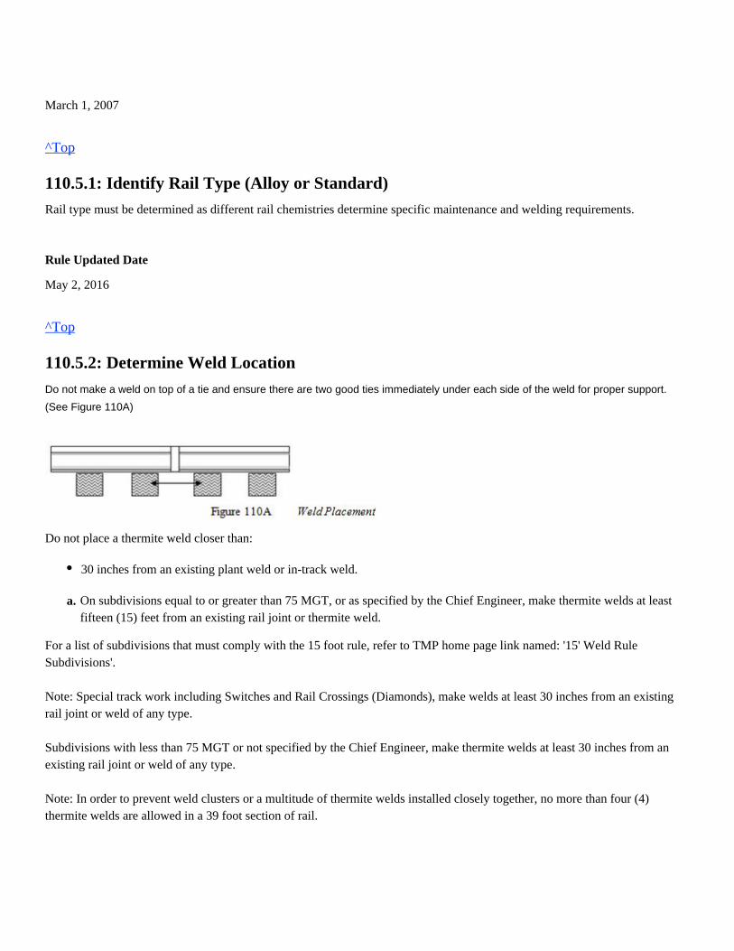
March 1, 2007
^Top
110.5.1: Identify Rail Type (Alloy or Standard)
Rail type must be determined as different rail chemistries determine specific maintenance and welding requirements.
Rule Updated Date
May 2, 2016
^Top
110.5.2: Determine Weld Location
Do not make a weld on top of a tie and ensure there are two good ties immediately under each side of the weld for proper support.
(See Figure 110A)
Do not place a thermite weld closer than:
For a list of subdivisions that must comply with the 15 foot rule, refer to TMP home page link named: '15' Weld RuleSubdivisions'.
Note: Special track work including Switches and Rail Crossings (Diamonds), make welds at least 30 inches from an existingrail joint or weld of any type.
Subdivisions with less than 75 MGT or not specified by the Chief Engineer, make thermite welds at least 30 inches from anexisting rail joint or weld of any type.
Note: In order to prevent weld clusters or a multitude of thermite welds installed closely together, no more than four (4)thermite welds are allowed in a 39 foot section of rail.
30 inches from an existing plant weld or in-track weld.
a. On subdivisions equal to or greater than 75 MGT, or as specified by the Chief Engineer, make thermite welds at leastfifteen (15) feet from an existing rail joint or thermite weld.
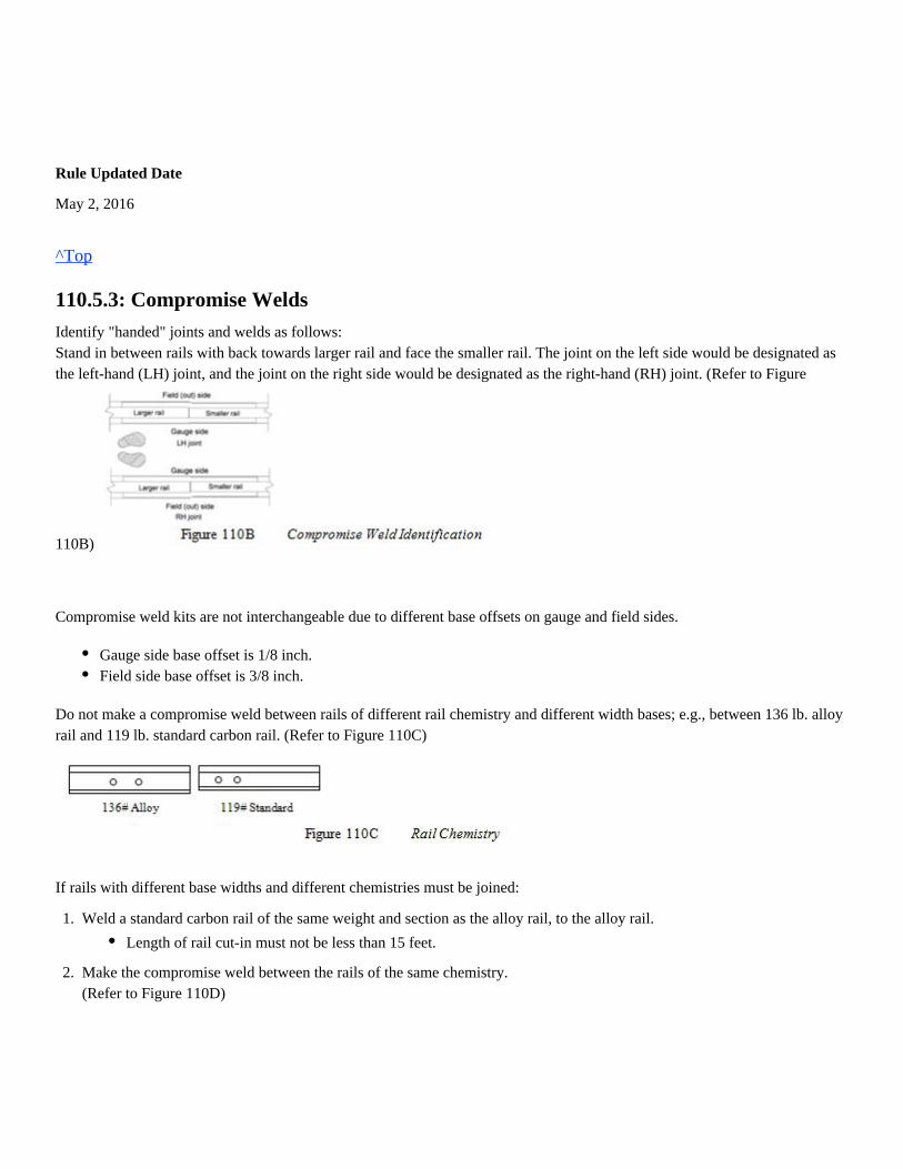
Rule Updated Date
May 2, 2016
^Top
110.5.3: Compromise Welds
Identify "handed" joints and welds as follows:Stand in between rails with back towards larger rail and face the smaller rail. The joint on the left side would be designated asthe left-hand (LH) joint, and the joint on the right side would be designated as the right-hand (RH) joint. (Refer to Figure
110B)
Compromise weld kits are not interchangeable due to different base offsets on gauge and field sides.
Do not make a compromise weld between rails of different rail chemistry and different width bases; e.g., between 136 lb. alloyrail and 119 lb. standard carbon rail. (Refer to Figure 110C)
If rails with different base widths and different chemistries must be joined:
Gauge side base offset is 1/8 inch.Field side base offset is 3/8 inch.
1.
2.
Weld a standard carbon rail of the same weight and section as the alloy rail, to the alloy rail.
Make the compromise weld between the rails of the same chemistry.(Refer to Figure 110D)
Length of rail cut-in must not be less than 15 feet.
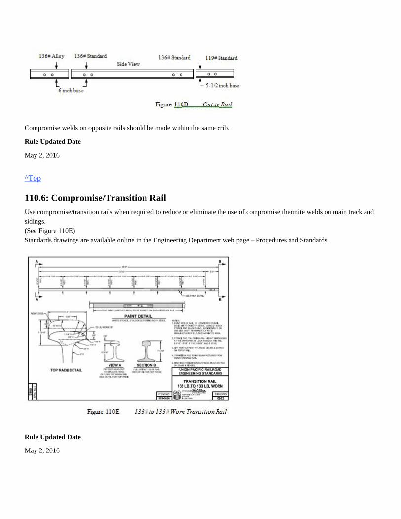
Compromise welds on opposite rails should be made within the same crib.
Rule Updated Date
May 2, 2016
^Top
110.6: Compromise/Transition Rail
Use compromise/transition rails when required to reduce or eliminate the use of compromise thermite welds on main track andsidings.(See Figure 110E)Standards drawings are available online in the Engineering Department web page – Procedures and Standards.
Rule Updated Date
May 2, 2016
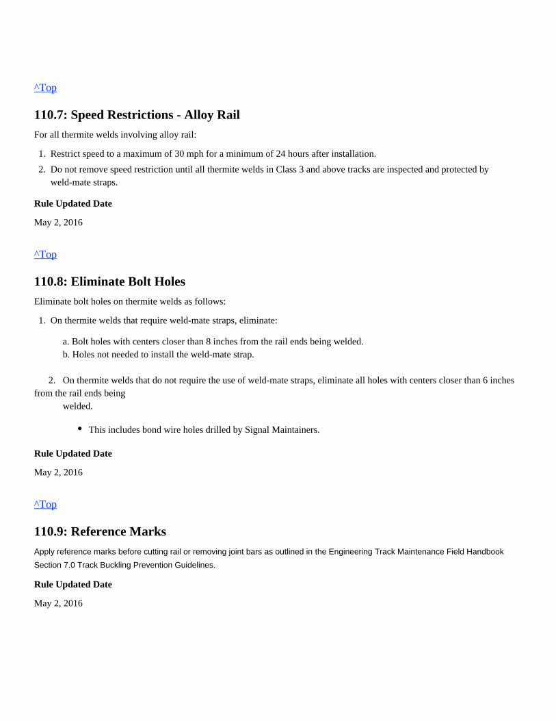
^Top
110.7: Speed Restrictions - Alloy Rail
For all thermite welds involving alloy rail:
Rule Updated Date
May 2, 2016
^Top
110.8: Eliminate Bolt Holes
Eliminate bolt holes on thermite welds as follows:
a. Bolt holes with centers closer than 8 inches from the rail ends being welded. b. Holes not needed to install the weld-mate strap.
2. On thermite welds that do not require the use of weld-mate straps, eliminate all holes with centers closer than 6 inchesfrom the rail ends being welded.
Rule Updated Date
May 2, 2016
^Top
110.9: Reference Marks
the Engineering Track Maintenance Field HandbookApply reference marks before cutting rail or removing joint bars as outlined in
Section 7.0 Track Buckling Prevention Guidelines.
Rule Updated Date
May 2, 2016
1.
2.
Restrict speed to a maximum of 30 mph for a minimum of 24 hours after installation.
Do not remove speed restriction until all thermite welds in Class 3 and above tracks are inspected and protected byweld-mate straps.
1. On thermite welds that require weld-mate straps, eliminate:
This includes bond wire holes drilled by Signal Maintainers.
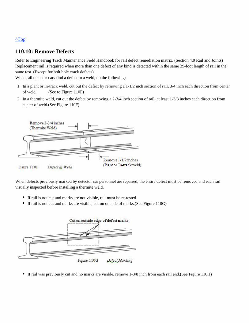
^Top
110.10: Remove Defects
Refer to Engineering Track Maintenance Field Handbook for rail defect remediation matrix. (Section 4.0 Rail and Joints)Replacement rail is required when more than one defect of any kind is detected within the same 39-foot length of rail in thesame test. (Except for bolt hole crack defects)When rail detector cars find a defect in a weld, do the following:
When defects previously marked by detector car personnel are repaired, the entire defect must be removed and each railvisually inspected before installing a thermite weld.
1.
2.
In a plant or in-track weld, cut out the defect by removing a 1-1/2 inch section of rail, 3/4 inch each direction from centerof weld. (See to Figure 110F)
In a thermite weld, cut out the defect by removing a 2-3/4 inch section of rail, at least 1-3/8 inches each direction fromcenter of weld.(See Figure 110F)
If rail is not cut and marks are not visible, rail must be re-tested.If rail is not cut and marks are visible, cut on outside of marks.(See Figure 110G)
If rail was previously cut and no marks are visible, remove 1-3/8 inch from each rail end.(See Figure 110H)
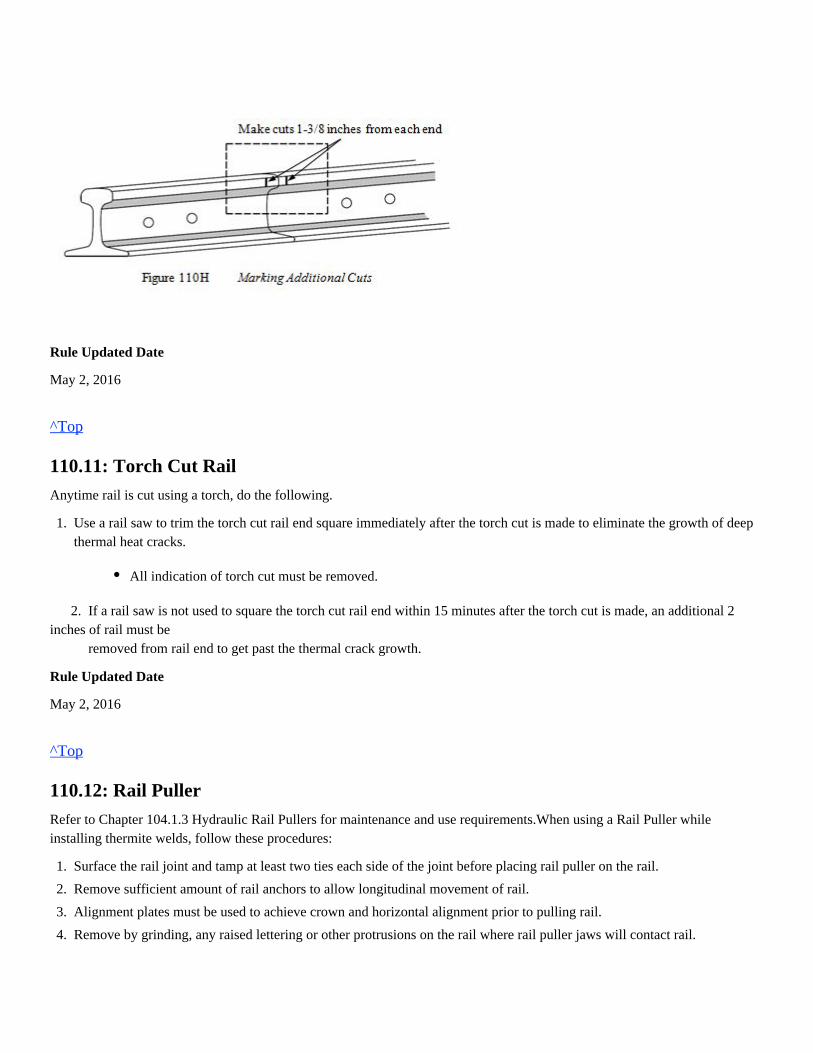
Rule Updated Date
May 2, 2016
^Top
110.11: Torch Cut Rail
Anytime rail is cut using a torch, do the following.
2. If a rail saw is not used to square the torch cut rail end within 15 minutes after the torch cut is made, an additional 2inches of rail must be removed from rail end to get past the thermal crack growth.
Rule Updated Date
May 2, 2016
^Top
110.12: Rail Puller
Refer to Chapter 104.1.3 Hydraulic Rail Pullers for maintenance and use requirements.When using a Rail Puller whileinstalling thermite welds, follow these procedures:
1. Use a rail saw to trim the torch cut rail end square immediately after the torch cut is made to eliminate the growth of deepthermal heat cracks.
All indication of torch cut must be removed.
1.
2.
3.
4.
5.
Surface the rail joint and tamp at least two ties each side of the joint before placing rail puller on the rail.
Remove sufficient amount of rail anchors to allow longitudinal movement of rail.
Alignment plates must be used to achieve crown and horizontal alignment prior to pulling rail.
Remove by grinding, any raised lettering or other protrusions on the rail where rail puller jaws will contact rail.
(Check the weld temperature on the top center of the weld using a 700° F temp-stick or a pyrometer. If the temp-stickdoes not melt or the pyrometer registers 700° F or less, remove the rail expander gradually)
Rule Updated Date
May 2, 2016
^Top
110.13: Clean Rail Ends
Clean rail ends removing dirt, rust or other material to ensure a sound weld.
Use an oxy-fuel torch to remove:
Use a wire brush to remove:
Rule Updated Date
March 1, 2007
^Top
110.14: Rail End Gap - Standard (1-inch) and Wide Gap Weld (WGW)
The required gap must be achieved to within 1/16 inch before thermite welding. Improper gap width results in improperpreheating or lack of sufficient weld material. Rails must be cut square to within 1/16 inch perpendicular from the top to the bottom and from the gage side to the field side.
When thermite welding, create the proper gap as follows:
5.
6.
7.
8.
9.
10.
Remove dirt or grease from this area using a wire brush or torch if necessary.
Clean and inspect the rail puller jaws for conditions that could reduce gripping.
Operate the rail puller to obtain the correct gap.
Never remove additional rail anchors while rail puller is under pressure.
If the desired pull cannot be achieved, release the expander, remove additional anchors, and repeat the process.
Remove rail puller after weld has cooled to 700° F or less.
Mill scale 3/4 inch from the each end of rail around the entire periphery.Grease 4 inches from each end of rail.
Dirt, rust or other material 4 inches from the end of each rail.- Visually inspect rail ends for defects
Combined deviation between both rails will not exceed 1/8 inch.
1.
2.
Create a 1 inch gap for a standard thermite weld.
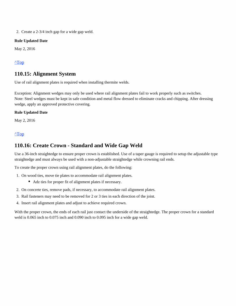
Rule Updated Date
May 2, 2016
^Top
110.15: Alignment System
Use of rail alignment plates is required when installing thermite welds. Exception: Alignment wedges may only be used where rail alignment plates fail to work properly such as switches.Note: Steel wedges must be kept in safe condition and metal flow dressed to eliminate cracks and chipping. After dressingwedge, apply an approved protective covering.
Rule Updated Date
May 2, 2016
^Top
110.16: Create Crown - Standard and Wide Gap Weld
Use a 36-inch straightedge to ensure proper crown is established. Use of a taper gauge is required to setup the adjustable typestraightedge and must always be used with a non-adjustable straightedge while crowning rail ends.
To create the proper crown using rail alignment plates, do the following:
With the proper crown, the ends of each rail just contact the underside of the straightedge. The proper crown for a standardweld is 0.065 inch to 0.075 inch and 0.090 inch to 0.095 inch for a wide gap weld.
2. Create a 2-3/4 inch gap for a wide gap weld.
1.
2.
3.
4.
On wood ties, move tie plates to accommodate rail alignment plates.
On concrete ties, remove pads, if necessary, to accommodate rail alignment plates.
Rail fasteners may need to be removed for 2 or 3 ties in each direction of the joint.
Insert rail alignment plates and adjust to achieve required crown.
Adz ties for proper fit of alignment plates if necessary.
(See Figure 110I)
Rule Updated Date
May 2, 2016
^Top
110.17: Rail Alignment (Straight and Compromise)
Rail twist is the mis-alignment of the rail head and base from the center axis and is not allowed. When making a weld, use a 36-inch straightedge to check the alignment of rails. Ensure that the gage side of the rails areperfectly aligned at the base of the rail first, then the head of the rail, lastly getting the proper crown. On rail joints where one rail is excessively curve worn, align rail on the field side of the head and base. On compromise joints where rails are of different base widths:
Compromise weld molds (handed weld molds) are designed with the offsets and are designated left-hand or right-hand.Compromise weld molds are not interchangeable and cannot be modified to fit other rail configurations.
Rule Updated Date
May 2, 2016
1.
2.
3.
Use alignment plates to achieve proper crown.
Align rails so that the base on the gage side has a 1/8 inch offset and that the base on the field side has a 3/8 inch offset.
Align rails so that the gage side of the head is perfectly aligned.
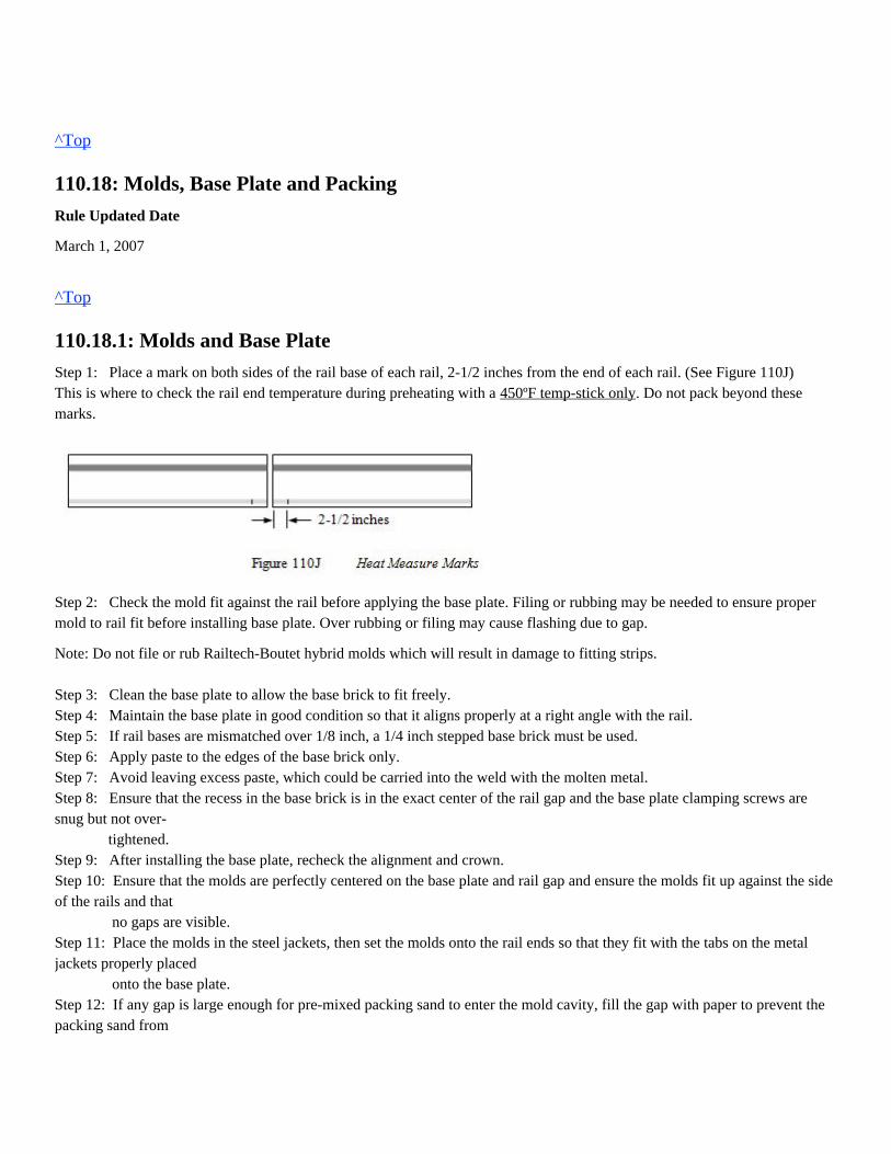
^Top
110.18: Molds, Base Plate and Packing
Rule Updated Date
March 1, 2007
^Top
110.18.1: Molds and Base Plate
Step 1: Place a mark on both sides of the rail base of each rail, 2-1/2 inches from the end of each rail. (See Figure 110J)This is where to check the rail end temperature during preheating with a . Do not pack beyond these450ºF temp-stick onlymarks.
Step 2: Check the mold fit against the rail before applying the base plate. Filing or rubbing may be needed to ensure propermold to rail fit before installing base plate. Over rubbing or filing may cause flashing due to gap.
Note: Do not file or rub Railtech-Boutet hybrid molds which will result in damage to fitting strips.
Step 3: Clean the base plate to allow the base brick to fit freely.Step 4: Maintain the base plate in good condition so that it aligns properly at a right angle with the rail.Step 5: If rail bases are mismatched over 1/8 inch, a 1/4 inch stepped base brick must be used.Step 6: Apply paste to the edges of the base brick only.Step 7: Avoid leaving excess paste, which could be carried into the weld with the molten metal.Step 8: Ensure that the recess in the base brick is in the exact center of the rail gap and the base plate clamping screws aresnug but not over- tightened.Step 9: After installing the base plate, recheck the alignment and crown.Step 10: Ensure that the molds are perfectly centered on the base plate and rail gap and ensure the molds fit up against the sideof the rails and that no gaps are visible.Step 11: Place the molds in the steel jackets, then set the molds onto the rail ends so that they fit with the tabs on the metaljackets properly placed onto the base plate.Step 12: If any gap is large enough for pre-mixed packing sand to enter the mold cavity, fill the gap with paper to prevent thepacking sand from
entering the cavity.Step 13: Place the mold clamp over the molds and jackets.Step 14: Tighten the mold clamp only enough to hold the molds firmly against the rail. Over tightening the mold clamp maycrack the molds.Step 15: Cover the top of the mold to prevent any foreign material from entering the mold cavity during packing.
Rule Updated Date
May 2, 2016
^Top
110.18.2: Packing
Pack the mold solid with pre-mix packing sand as follows:
3. Ensure packing sand does not enter the mold cavity. 4. If packing sand does enter the mold cavity, disassemble the mold, remove the sand mixture and repack the mold.
Plan the packing stage so that the preheating cycle can begin immediately after the packing is complete. Once the packing iscomplete, do notallow the finished mold to sit more than 10 minutes before preheating.
Rule Updated Date
May 2, 2016
^Top
110.19: Position Slag Basin
To allow the slag to flow out of the risers properly:
Rule Updated Date
March 1, 2007
1.
2.
Tightly seal all seams and joints with a minimum thickness of packing sand to ensure that all voids are filled.
Apply a second layer of packing sand by pressing firmly into place with your finger tips or palm.
Do not pound against the pre-mix packing sand, as this pounding may jar the rail and cause it to mis-align.
On tangent track, position the slag basin on the inside of the rail (gauge side).On curves, position the slag basin on the low side of the rail.
^Top
110.20: Preheating Procedures
Before preheating, ensure you are familiar with and have been properly trained in the operation of that equipment. Approvedtorch stand must be used when preheating thermite welds. Torch must be level and torch height checked prior to preheating.
Rule Updated Date
May 2, 2016
^Top
110.20.1: Use of Oxy-Propane Equipment
Use a Victor HD310C torch body or equivalent with the Railtech flat head or Victor TWN-5 rectangular torch tip.
These pressure settings are required at the torch and are shown for both standard 1 inch and wide gap welds and assume thetorch has 50 feet of 3/8 inch ID Grade "T" hose, check valves and flashback arrestors. (Refer to Table 110A)
Verify the oxygen and propane pressures at the torch and adjust if necessary.
The following pressure settings are required at the torch.The torch must be in the molds and flame adjusted properly to achieve these settings.
Table 110A Torch PSI Requirement
Standard 1 inch Weld Wide Gap Weld
Propane 15 psi 15 psi
Oxygen 60 psi 60 psi
1. Use of a stopwatch is required when thermite welding for preheat, tap and take down times.
Pressure settings may vary for each set of equipment and should be adjusted accordingly.Torch mounted in-line gauges must be used to verify pressure settings on every weld and will be placed between torchhandle and flashback arrestors.Extreme pressure variances of 15 psi or more between cylinder regulator and in-line gauge indicates a restriction orproblem, and must be corrected.Ensure there is sufficient oxygen and fuel-gas in cylinders to complete the preheating.
1.
2.
3.
4.
5.
Do not use hose lengths greater than 100 feet.
Operate torch 1-1/2 inches above the top of the rail for standard 1 inch weld.
Operate torch 2-3/8 inches above the top of the rail for wide gap weld.
Ignite the oxy-propane torch and place onto rail mounted torch stand.
Adjust for full oxygen by opening the oxygen valve completely.
Rule Updated Date
May 2, 2016
^Top
110.20.2: Start the Preheat Process (Refer to Table 110B)
Preheat times are as follows: (Refer to Table 110B)
Table 110B Preheat Times
Standard 1 inch Welds Wide Gap Welds
5-1/2 inch rail base – 119# or smaller 5 to 5-1/2 minutes 6 minutes
6 inch rail base – larger than 119# 6 to 6-1/2 minutes 6 minutes
Do not exceed 8 minutes when preheating
Rule Updated Date
May 2, 2016
^Top
110.20.3: Monitor Preheating Process
Wear the required PPE when monitoring the preheat process.
If rail end melting occurs: Stop, tear down molds, re-cut rail ends and start over.
Preheating is completed when the required preheat time has been achieved the rail base is 450° F on all four sides. (At theandmarks measured 2-1/2 inches from the end of rails with a ). temp-stick only Do not use a pyrometer to check rail base
6. Open the propane valve until a crackle sound occurs, then slowly close the propane valve until the crackle sounddisappears.
Ensure the torch is centered and straight.The employee igniting and placing the torch must observe the entire preheating of the rail ends.Ensure the rail ends do not melt.Ensure the rail ends and molds heat evenly to prevent improper fusion and internal cracks that result from unevencooling.Ensure that the web glows a bright red/orange with no signs of sweating or melting.- If rail ends appear to be getting too hot, cool the flame by increasing the propane at the torch handle.Ensure the rail head and base glow a dull red and have no black areas.After removing the torch, observe the true color of the rail ends. If they do not hold their color, replace the torch andcontinue preheating.
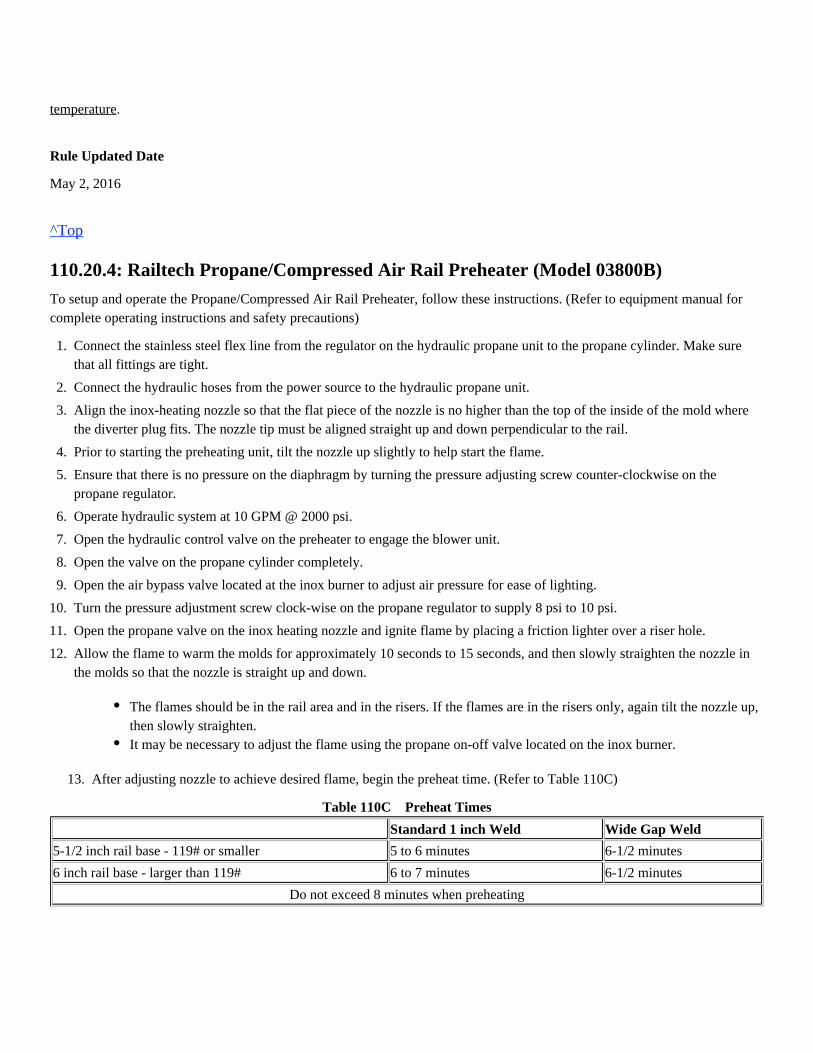
.temperature
Rule Updated Date
May 2, 2016
^Top
110.20.4: Railtech Propane/Compressed Air Rail Preheater (Model 03800B)
To setup and operate the Propane/Compressed Air Rail Preheater, follow these instructions. (Refer to equipment manual forcomplete operating instructions and safety precautions)
13. After adjusting nozzle to achieve desired flame, begin the preheat time. (Refer to Table 110C)
Table 110C Preheat Times
Standard 1 inch Weld Wide Gap Weld
5-1/2 inch rail base - 119# or smaller 5 to 6 minutes 6-1/2 minutes
6 inch rail base - larger than 119# 6 to 7 minutes 6-1/2 minutes
Do not exceed 8 minutes when preheating
1.
2.
3.
4.
5.
6.
7.
8.
9.
10.
11.
12.
Connect the stainless steel flex line from the regulator on the hydraulic propane unit to the propane cylinder. Make surethat all fittings are tight.
Connect the hydraulic hoses from the power source to the hydraulic propane unit.
Align the inox-heating nozzle so that the flat piece of the nozzle is no higher than the top of the inside of the mold wherethe diverter plug fits. The nozzle tip must be aligned straight up and down perpendicular to the rail.
Prior to starting the preheating unit, tilt the nozzle up slightly to help start the flame.
Ensure that there is no pressure on the diaphragm by turning the pressure adjusting screw counter-clockwise on thepropane regulator.
Operate hydraulic system at 10 GPM @ 2000 psi.
Open the hydraulic control valve on the preheater to engage the blower unit.
Open the valve on the propane cylinder completely.
Open the air bypass valve located at the inox burner to adjust air pressure for ease of lighting.
Turn the pressure adjustment screw clock-wise on the propane regulator to supply 8 psi to 10 psi.
Open the propane valve on the inox heating nozzle and ignite flame by placing a friction lighter over a riser hole.
Allow the flame to warm the molds for approximately 10 seconds to 15 seconds, and then slowly straighten the nozzle inthe molds so that the nozzle is straight up and down.
The flames should be in the rail area and in the risers. If the flames are in the risers only, again tilt the nozzle up,then slowly straighten.It may be necessary to adjust the flame using the propane on-off valve located on the inox burner.
14. Preheating is completed when the required preheat time has been achieved the rail base is 450° F on all four sides.and(At the marks measured 2-1/2 inches from the end of rails with a ). temp-stick only Do not use a pyrometer to check rail base
.temperature
Rule Updated Date
May 2, 2016
^Top
110.21: Crucible
While preheating the molds and rail ends:
When preheat is complete, remove the torch and insert the diverter plug in the top of the mold, pushing the plug down firmly.
Do not pound the plug into place.
Note: The diverter plug allows the molten steel to flow into the mold properly, filling the mold evenly.Place the crucible onto the molds and center over diverter plug, using the two large riser holes as a guide.
Rule Updated Date
May 2, 2016
^Top
110.22: Igniting and Pouring
To ignite the charge:
Tap Time: The time it takes after igniting the charge for the molten steel to flow out of the crucible.
Inspect crucible for loose sand and cracks.Do not use if cracks are present or has a loose thimble.Do not place crucible directly on any surface that may allow foreign material to stick to the bottom.Fill the crucible with the charge.Warm the diverter plug 30 seconds prior to removing the preheat torch by placing it on the top edge of the mold.
When using a stick igniter, light the igniter by touching it on the inside of the riser hole.Place the stick igniter in the charge within the crucible to a depth of and step back. (Do not over insert)1-inchDo not use an oxy-fuel torch to ignite the stick igniter or thermite weld charge.
Acceptable tap time is 15 seconds to 35 seconds.If tap time is less than 15 seconds or more than 35 seconds, the weld must be considered defective and removed fromtrack.
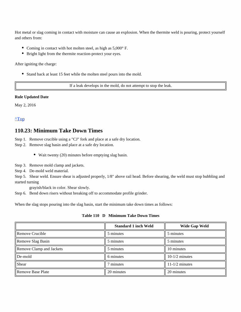
Hot metal or slag coming in contact with moisture can cause an explosion. When the thermite weld is pouring, protect yourselfand others from:
After igniting the charge:
If a leak develops in the mold, do not attempt to stop the leak.
Rule Updated Date
May 2, 2016
^Top
110.23: Minimum Take Down Times
Step 1. Remove crucible using a "CJ" fork and place at a safe dry location.Step 2. Remove slag basin and place at a safe dry location.
Step 3. Remove mold clamp and jackets.Step 4. De-mold weld material.Step 5. Shear weld. Ensure shear is adjusted properly, 1/8" above rail head. Before shearing, the weld must stop bubbling andstarted turning grayish/black in color. Shear slowly.Step 6. Bend down risers without breaking off to accommodate profile grinder.
When the slag stops pouring into the slag basin, start the minimum take down times as follows:
Table 110 D Minimum Take Down Times
Standard 1 inch Weld Wide Gap Weld
Remove Crucible 5 minutes 5 minutes
Remove Slag Basin 5 minutes 5 minutes
Remove Clamp and Jackets 5 minutes 10 minutes
De-mold 6 minutes 10-1/2 minutes
Shear 7 minutes 11-1/2 minutes
Remove Base Plate 20 minutes 20 minutes
Coming in contact with hot molten steel, as high as 5,000° F.Bright light from the thermite reaction-protect your eyes.
Stand back at least 15 feet while the molten steel pours into the mold.
Wait twenty (20) minutes before emptying slag basin.
Remove Alignment Tools and Empty Slag Pan 20 minutes 20 minutes
Remove Risers 25 minutes or 900° F 900° F
Remove Rail Puller When weld is less than 700° F When weld is less than 700° F
After removing slag pan, place it in a safe dry location where it can continue to cool.
Rule Updated Date
May 2, 2016
General Order
Effective Date: May 2, 2016
^Top
110.24: Remove Excess Mold
Follow these safety requirements when removing mold material:
Rule Updated Date
May 2, 2016
^Top
110.25: Rough Grinding
Rough grinding of the rail head portion of the thermite weld can be performed after shearing. Rough grinding of the runningsurface of the rail shall be performed with a surface grinder and is completed when the excess weld material is reduced toapproximately 30 thousandths (0.030) of an inch.
When the surface of the weld is above 700° F, it is permitted to "blue" the weld.
Remove alignment plates and base plate in accordance with take down times.
Remove risers by lightly tapping downward toward ground.
1.
2.
3.
4.
5.
Wrap-around face shield with goggles or safety glasses must be worn when removing the mold and cleaning the weld, or
Mono-goggle XTR with safety glasses can be used as an alternative.
Protect yourself from hot metal fragments and sand.
Do not discard the hot slag where someone could step on it, or where it could start a grass fire.
Do not discard hot slag on wet soil, snow or throw into water.
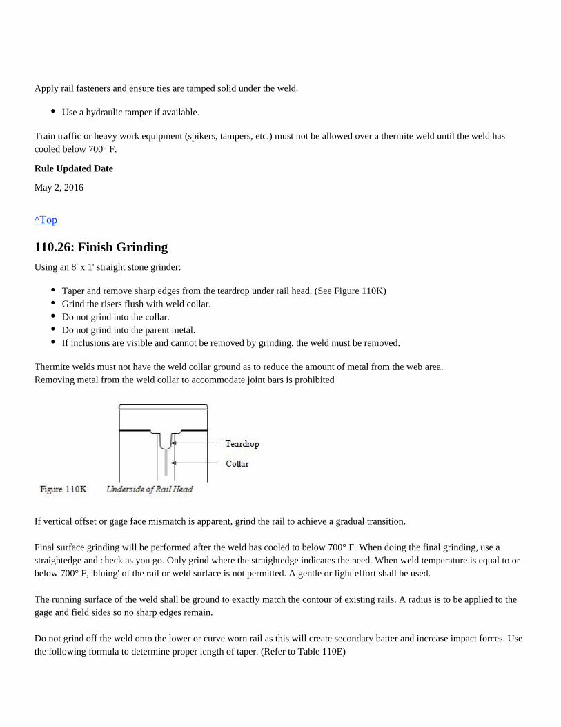
Apply rail fasteners and ensure ties are tamped solid under the weld.
Train traffic or heavy work equipment (spikers, tampers, etc.) must not be allowed over a thermite weld until the weld hascooled below 700° F.
Rule Updated Date
May 2, 2016
^Top
110.26: Finish Grinding
Using an 8' x 1' straight stone grinder:
Thermite welds must not have the weld collar ground as to reduce the amount of metal from the web area.Removing metal from the weld collar to accommodate joint bars is prohibited
If vertical offset or gage face mismatch is apparent, grind the rail to achieve a gradual transition. Final surface grinding will be performed after the weld has cooled to below 700° F. When doing the final grinding, use astraightedge and check as you go. Only grind where the straightedge indicates the need. When weld temperature is equal to orbelow 700° F, 'bluing' of the rail or weld surface is not permitted. A gentle or light effort shall be used.
The running surface of the weld shall be ground to exactly match the contour of existing rails. A radius is to be applied to thegage and field sides so no sharp edges remain.
Do not grind off the weld onto the lower or curve worn rail as this will create secondary batter and increase impact forces. Usethe following formula to determine proper length of taper. (Refer to Table 110E)
Use a hydraulic tamper if available.
Taper and remove sharp edges from the teardrop under rail head. (See Figure 110K)Grind the risers flush with weld collar.Do not grind into the collar.Do not grind into the parent metal.If inclusions are visible and cannot be removed by grinding, the weld must be removed.
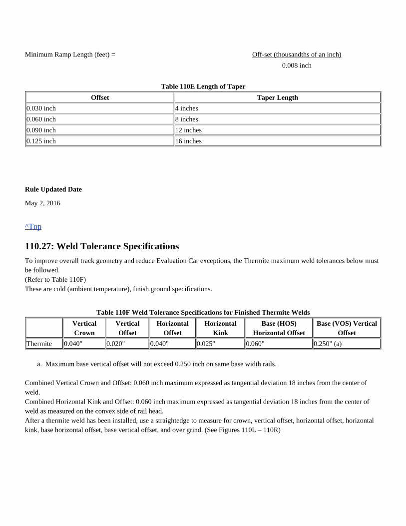
Minimum Ramp Length (feet) = Off-set (thousandths of an inch)
0.008 inch
Table 110E Length of Taper
Offset Taper Length
0.030 inch 4 inches
0.060 inch 8 inches
0.090 inch 12 inches
0.125 inch 16 inches
Rule Updated Date
May 2, 2016
^Top
110.27: Weld Tolerance Specifications
To improve overall track geometry and reduce Evaluation Car exceptions, the Thermite maximum weld tolerances below mustbe followed.(Refer to Table 110F)These are cold (ambient temperature), finish ground specifications.
Table 110F Weld Tolerance Specifications for Finished Thermite Welds
VerticalCrown
VerticalOffset
HorizontalOffset
HorizontalKink
Base (HOS)Horizontal Offset
Base (VOS) VerticalOffset
Thermite 0.040" 0.020" 0.040" 0.025" 0.060" 0.250" (a)
a. Maximum base vertical offset will not exceed 0.250 inch on same base width rails.
Combined Vertical Crown and Offset: 0.060 inch maximum expressed as tangential deviation 18 inches from the center ofweld.Combined Horizontal Kink and Offset: 0.060 inch maximum expressed as tangential deviation 18 inches from the center ofweld as measured on the convex side of rail head.After a thermite weld has been installed, use a straightedge to measure for crown, vertical offset, horizontal offset, horizontalkink, base horizontal offset, base vertical offset, and over grind. (See Figures 110L – 110R)
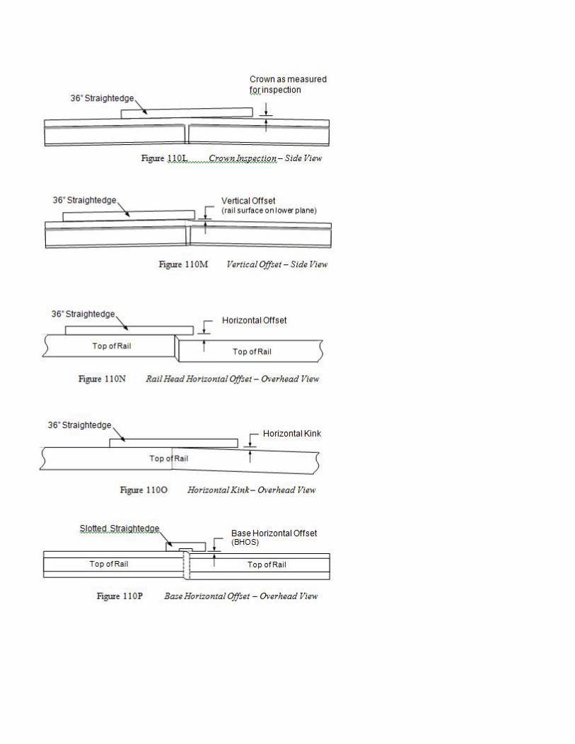
Welds must not be over ground. Use the straightedge periodically to check progress.
Rule Updated Date
May 2, 2016
^Top
110.28: Identify Weld
The engineering department requires the placement of metal weld tags on all welds. Use a generous amount of adhesive on theback of the tag and place on the field side of the rail. (See Figures 110S and 110T). Thermite weld tags will be punched to indicate the following:
1.
2.
3.
4.
Employee ID (not gang number)
Month and year installed
Month and year weld kit manufactured
1-inch gap or wide gap weld
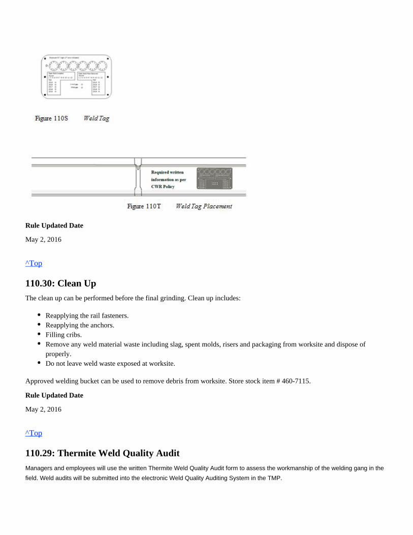
Rule Updated Date
May 2, 2016
^Top
110.30: Clean Up
The clean up can be performed before the final grinding. Clean up includes:
Approved welding bucket can be used to remove debris from worksite. Store stock item # 460-7115.
Rule Updated Date
May 2, 2016
^Top
110.29: Thermite Weld Quality Audit
Managers and employees will use the written Thermite Weld Quality Audit form to assess the workmanship of the welding gang in the
field. Weld audits will be submitted into the electronic Weld Quality Auditing System in the TMP.
Reapplying the rail fasteners.Reapplying the anchors.Filling cribs.Remove any weld material waste including slag, spent molds, risers and packaging from worksite and dispose ofproperly.Do not leave weld waste exposed at worksite.
Rule Updated Date
May 2, 2016
^Top
110.32: Thermite Head Wash Weld
Only designated track welding employees who have been trained and qualified are allowed to install thermite head wash welds.All PPE must be worn as required for any thermite welding procedure.When performing dye-penetrant testing, wear wrap-around face shield with goggles or safety glasses.
Railtech-Boutet kits are available for 115# and 132#/136# rail.On Railtech-Boutet welds, the rail head is removed by grinding except the lower 1/4 inch. Defect must not be in or below this
1/4 inch.Head wash welds use wide gap weld hardware.
Rule Updated Date
May 2, 2016
^Top
110.32.1: Rail Preparation
Rule Updated Date
May 2, 2016
^Top
110.31: Welders Log Booklet
Mono-goggle XTR with safety glasses can be used as an alternative.
1.
2.
3.
4.
5.
6.
Do not weld on non-alloy rail when the rail temperature is below 5° F.
Use an oxy-fuel torch and wire brush to clean the rail of any dirt, oil, grease or other contaminants.
Using rail alignment tool, pre-crown the rail to 0.045 inch using a 36 inch straightedge and taper gauge before grinding the2 inch slot.
Mark the rail for depth of grind on both sides of the rail head using the depth tool.
Remove by grinding, the entire defect within the rail head leaving 1/4 inch of the rail head.
After grinding the 2 inch slot, adjust crown to 0.060 inch to 0.070 inch.
Warm rail to remove any surface moisture around entire periphery of rail.
The ground surface must be level and even on both sides of the rail head.
Use a file or hand grinder if necessary to remove any sharp edge after defect removal.
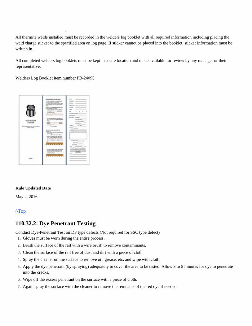
110.31: Welders Log Booklet
All thermite welds installed must be recorded in the welders log booklet with all required information including placing theweld charge sticker to the specified area on log page. If sticker cannot be placed into the booklet, sticker information must bewritten in.
All completed welders log booklets must be kept in a safe location and made available for review by any manager or theirrepresentative.
Welders Log Booklet item number PB-24095.
Rule Updated Date
May 2, 2016
^Top
110.32.2: Dye Penetrant Testing
Conduct Dye-Penetrant Test on DF type defects (Not required for SSC type defect)1.
2.
3.
4.
5.
6.
7.
8.
Gloves must be worn during the entire process.
Brush the surface of the rail with a wire brush to remove contaminants.
Clean the surface of the rail free of dust and dirt with a piece of cloth.
Spray the cleaner on the surface to remove oil, grease, etc. and wipe with cloth.
Apply the dye penetrant (by spraying) adequately to cover the area to be tested. Allow 3 to 5 minutes for dye to penetrateinto the cracks.
Wipe off the excess penetrant on the surface with a piece of cloth.
Again spray the surface with the cleaner to remove the remnants of the red dye if needed.
Rule Updated Date
May 2, 2016
^Top
110.32.3: Torch Height
Rule Updated Date
May 2, 2016
^Top
110.32.4: Molds and Clamp
Rule Updated Date
May 2, 2016
^Top
110.32.5: Preheating (Oxy-fuel Torch)
(Refer to Table 110G and Table 110H)
Table 110G Pressure Settings
8.
9.
Spray the developer evenly on the surface to give a thin even layer. This layer absorbs the penetrant from the cracks andred spots or lines appear on the surface to give a visible indication of the flaws.
The crack if any will be indicated with the red dye absorbed by the white developer.
Remove white developer before proceeding.
1.
2.
Pre-set oxy-fuel torch height to 4-1/8 inches.
Pre-set inox burner torch height to 3-3/8 inches.
1.
2.
3.
4.
Place molds and clamp.
Cover top of molds before beginning packing to prevent contaminants from entering mold cavity.
Pack molds with packing mud (molds are similar to wide gap molds).
Place slag pan.
Molds may need to be filed / rubbed to ensure a tight fit to rail.
Care must be taken to not over file or rub as this may cause flashing.
1. Preheating using an oxy-fuel torch:
Oxygen Propane
115# / 119# 50 psi 15 psi
132# / 136# 50 psi 15 psi
133#
141#
Table 110H Preheat Time
Preheat Time
115# / 119# 5 minutes
132# / 136# 5 minutes
133#
141#
2. In-line gauges are required as specified by UPRR track welding rules to provide accurate preheat when using anoxy-fuel torch. 3. When using an oxy-fuel torch, ignite torch before placing into molds, adjust flame and re- adjust pressure settings ifneeded. 4. Adjust (open) propane control valve on torch handle if needed to cool the flame. 5. Monitor preheat during entire process to ensure no melting of rail occurs.
Rule Updated Date
May 2, 2016
^Top
110.32.6: Preheating (Forced Air/Propane Torch)
1. Preheating using a forced air/propane torch: (Refer to Table 110I and Table 110J)
Table 110I Pressure Settings
Air Propane
115# / 119# 2 to 2-1/2 psi 8 to 12 psi
132# / 136# 2 to 2-1/2 psi 8 to 12 psi
133#
141#
Table 110J Preheat Time
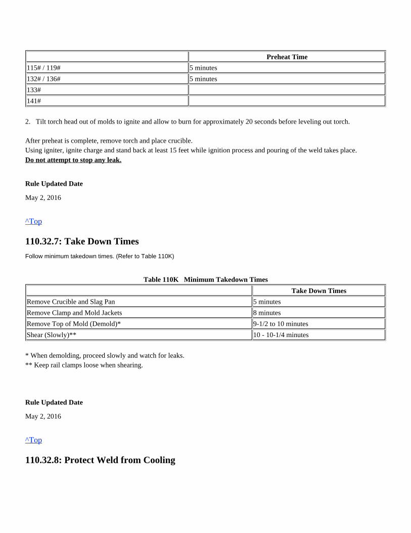
Preheat Time
115# / 119# 5 minutes
132# / 136# 5 minutes
133#
141#
2. Tilt torch head out of molds to ignite and allow to burn for approximately 20 seconds before leveling out torch.
After preheat is complete, remove torch and place crucible.Using igniter, ignite charge and stand back at least 15 feet while ignition process and pouring of the weld takes place.
Do not attempt to stop any leak.
Rule Updated Date
May 2, 2016
^Top
110.32.7: Take Down Times
Follow minimum takedown times. (Refer to Table 110K)
Table 110K Minimum Takedown Times
Take Down Times
Remove Crucible and Slag Pan 5 minutes
Remove Clamp and Mold Jackets 8 minutes
Remove Top of Mold (Demold)* 9-1/2 to 10 minutes
Shear (Slowly)** 10 - 10-1/4 minutes
* When demolding, proceed slowly and watch for leaks. ** Keep rail clamps loose when shearing.
Rule Updated Date
May 2, 2016
^Top
110.32.8: Protect Weld from Cooling
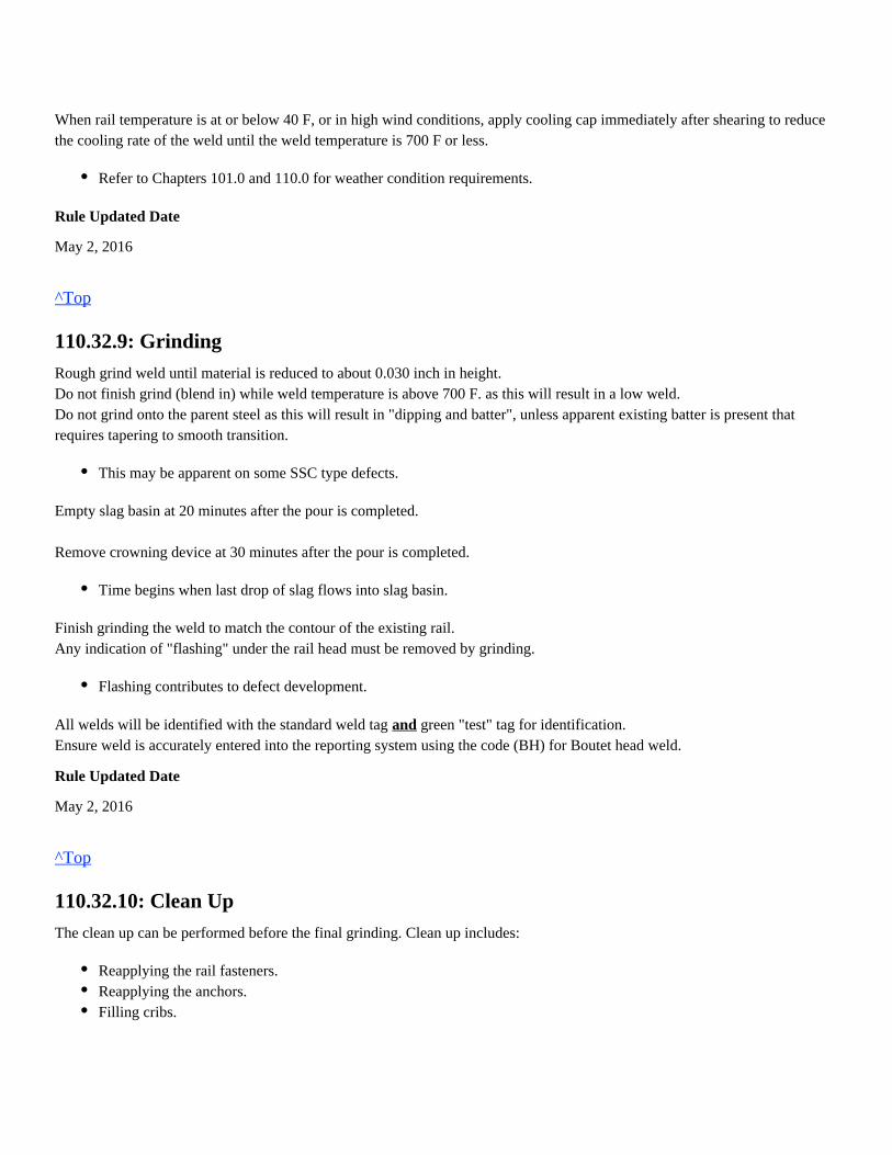
When rail temperature is at or below 40 F, or in high wind conditions, apply cooling cap immediately after shearing to reducethe cooling rate of the weld until the weld temperature is 700 F or less.
Rule Updated Date
May 2, 2016
^Top
110.32.9: Grinding
Rough grind weld until material is reduced to about 0.030 inch in height.Do not finish grind (blend in) while weld temperature is above 700 F. as this will result in a low weld.Do not grind onto the parent steel as this will result in "dipping and batter", unless apparent existing batter is present thatrequires tapering to smooth transition.
Empty slag basin at 20 minutes after the pour is completed. Remove crowning device at 30 minutes after the pour is completed.
Finish grinding the weld to match the contour of the existing rail.Any indication of "flashing" under the rail head must be removed by grinding.
All welds will be identified with the standard weld tag green "test" tag for identification.andEnsure weld is accurately entered into the reporting system using the code (BH) for Boutet head weld.
Rule Updated Date
May 2, 2016
^Top
110.32.10: Clean Up
The clean up can be performed before the final grinding. Clean up includes:
Refer to Chapters 101.0 and 110.0 for weather condition requirements.
This may be apparent on some SSC type defects.
Time begins when last drop of slag flows into slag basin.
Flashing contributes to defect development.
Reapplying the rail fasteners.Reapplying the anchors.Filling cribs.
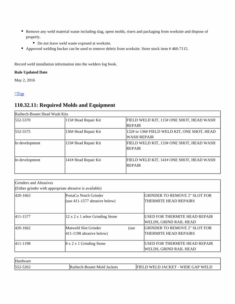
Record weld installation information into the welders log book.
Rule Updated Date
May 2, 2016
^Top
110.32.11: Required Molds and Equipment
Railtech-Boutet Head Wash Kits
552-5370 115# Head Repair Kit FIELD WELD KIT, 115# ONE SHOT, HEAD WASHREPAIR
552-5575 136# Head Repair Kit 132# to 136# FIELD WELD KIT, ONE SHOT, HEADWASH REPAIR
In development
133# Head Repair Kit FIELD WELD KIT, 133# ONE SHOT, HEAD WASHREPAIR
In development
141# Head Repair Kit FIELD WELD KIT, 141# ONE SHOT, HEAD WASHREPAIR
Grinders and Abrasives(Either grinder with appropriate abrasive is available)
420-1663 PortaCo Notch Grinder (use 411-1577 abrasive below)
GRINDER TO REMOVE 2" SLOT FORTHERMITE HEAD REPAIRS
411-1577 12 x 2 x 1 arbor Grinding Stone USED FOR THERMITE HEAD REPAIRWELDS, GRIND RAIL HEAD
420-1662 Matweld Slot Grinder (use411-1198 abrasive below)
GRINDER TO REMOVE 2" SLOT FORTHERMITE HEAD REPAIRS
411-1198 8 x 2 x 1 Grinding Stone USED FOR THERMITE HEAD REPAIRWELDS, GRIND RAIL HEAD
Hardware
552-5263 Railtech-Boutet Mold Jackets FIELD WELD JACKET - WIDE GAP WELD
Remove any weld material waste including slag, spent molds, risers and packaging from worksite and dispose ofproperly.
Approved welding bucket can be used to remove debris from worksite. Store stock item # 460-7115.Do not leave weld waste exposed at worksite.
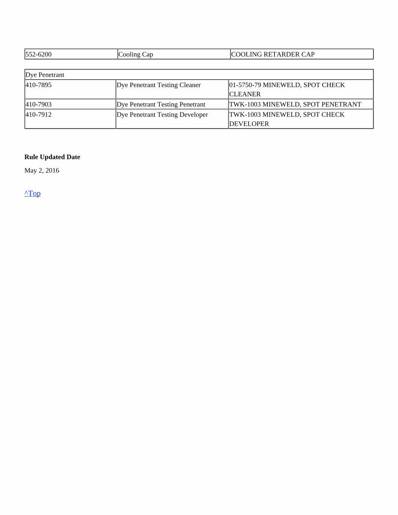
552-6200 Cooling Cap COOLING RETARDER CAP
Dye Penetrant
410-7895 Dye Penetrant Testing Cleaner 01-5750-79 MINEWELD, SPOT CHECKCLEANER
410-7903 Dye Penetrant Testing Penetrant TWK-1003 MINEWELD, SPOT PENETRANT
410-7912 Dye Penetrant Testing Developer TWK-1003 MINEWELD, SPOT CHECKDEVELOPER
Rule Updated Date
May 2, 2016
^Top
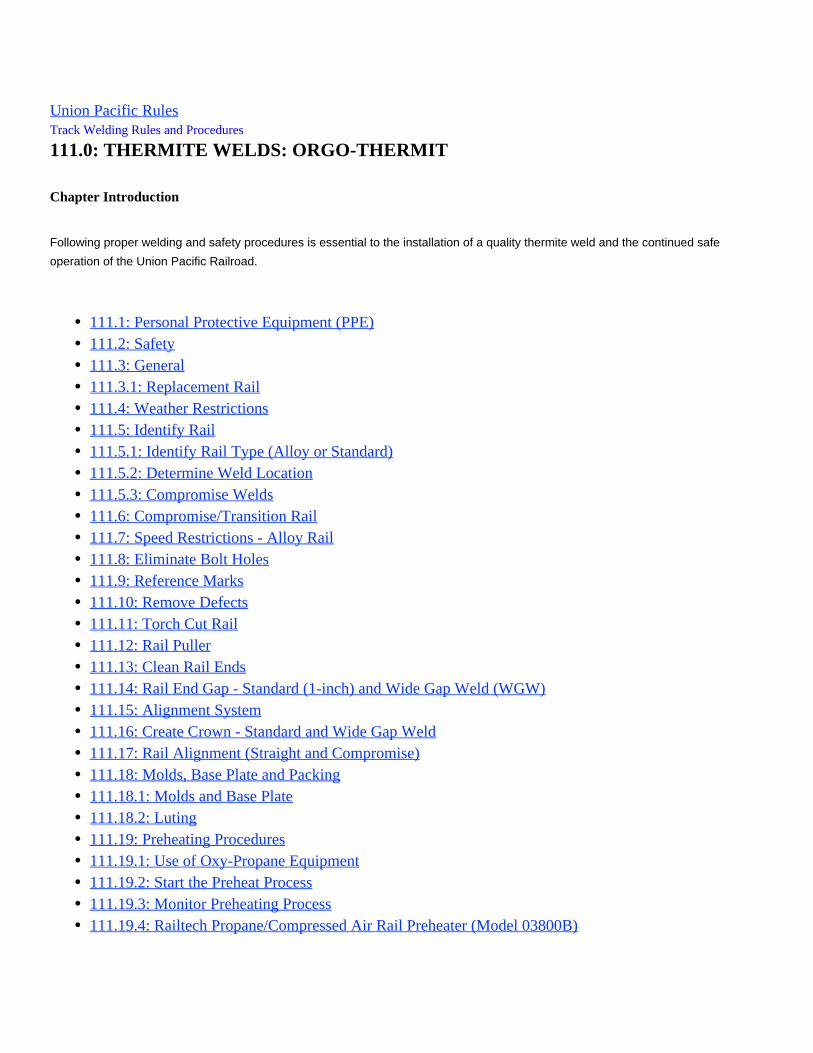
Union Pacific Rules Track Welding Rules and Procedures
111.0: THERMITE WELDS: ORGO-THERMIT
Chapter Introduction
Following proper welding and safety procedures is essential to the installation of a quality thermite weld and the continued safe
operation of the Union Pacific Railroad.
111.1: Personal Protective Equipment (PPE)111.2: Safety111.3: General111.3.1: Replacement Rail111.4: Weather Restrictions111.5: Identify Rail111.5.1: Identify Rail Type (Alloy or Standard)111.5.2: Determine Weld Location111.5.3: Compromise Welds111.6: Compromise/Transition Rail111.7: Speed Restrictions - Alloy Rail111.8: Eliminate Bolt Holes111.9: Reference Marks111.10: Remove Defects111.11: Torch Cut Rail111.12: Rail Puller111.13: Clean Rail Ends111.14: Rail End Gap - Standard (1-inch) and Wide Gap Weld (WGW)111.15: Alignment System111.16: Create Crown - Standard and Wide Gap Weld111.17: Rail Alignment (Straight and Compromise)111.18: Molds, Base Plate and Packing111.18.1: Molds and Base Plate111.18.2: Luting111.19: Preheating Procedures111.19.1: Use of Oxy-Propane Equipment111.19.2: Start the Preheat Process111.19.3: Monitor Preheating Process111.19.4: Railtech Propane/Compressed Air Rail Preheater (Model 03800B)
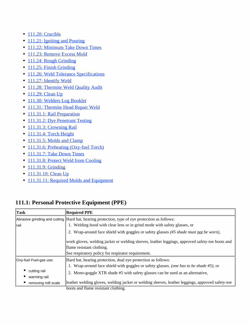
Hard hat, hearing protection, dual eye protection as follows:
leather welding gloves, welding jacket or welding sleeves, leather leggings, approved safety-toeboots and flame resistant clothing.
Hard hat, hearing protection, type of eye protection as follows:
work gloves, welding jacket or welding sleeves, leather leggings, approved safety-toe boots andflame resistant clothing.
111.1: Personal Protective Equipment (PPE)
Task Required PPE
Abrasive grinding and cutting
rail
See respiratory policy for respirator requirement.
Oxy-fuel Fuel-gas use:
111.20: Crucible111.21: Igniting and Pouring111.22: Minimum Take Down Times111.23: Remove Excess Mold111.24: Rough Grinding111.25: Finish Grinding111.26: Weld Tolerance Specifications111.27: Identify Weld111.28: Thermite Weld Quality Audit111.29: Clean Up111.30: Welders Log Booklet111.31: Thermite Head Repair Weld111.31.1: Rail Preparation111.31.2: Dye Penetrant Testing111.31.3: Crowning Rail111.31.4: Torch Height111.31.5: Molds and Clamp111.31.6: Preheating (Oxy-fuel Torch)111.31.7: Take Down Times111.31.8: Protect Weld from Cooling111.31.9: Grinding111.31.10: Clean Up111.31.11: Required Molds and Equipment
1.
2.
Welding hood with clear lens or in grind mode with safety glasses, or
Wrap-around face shield with goggles or safety glasses (#5 shade must be worn),not
cutting rail
warming rail
removing mill scale
1.
2.
Wrap-around face shield with goggles or safety glasses. or(one has to be shade #5),
Mono-goggle XTR shade #5 with safety glasses can be used as an alternative,
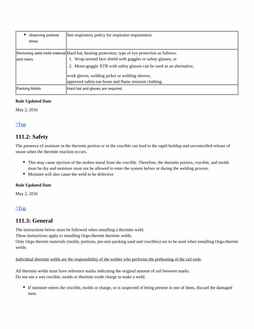
Hard hat, hearing protection, type of eye protection as follows:
work gloves, welding jacket or welding sleeves,
See respiratory policy for respirator requirement.
Removing weld mold material
and risers
approved safety-toe boots and flame resistant clothing.
Packing Molds Hard hat and gloves are required.
Rule Updated Date
May 2, 2016
^Top
111.2: Safety
The presence of moisture in the thermite portion or in the crucible can lead to the rapid buildup and uncontrolled release ofsteam when the thermite reaction occurs.
Rule Updated Date
May 2, 2016
^Top
111.3: General
The instructions below must be followed when installing a thermite weld.These instructions apply to installing Orgo-thermit thermite welds.Only Orgo-thermit materials (molds, portions, pre-mix packing sand and crucibles) are to be used when installing Orgo-thermitwelds.
.Individual thermite welds are the responsibility of the welder who performs the preheating of the rail ends
All thermite welds must have reference marks indicating the original amount of rail between marks.Do not use a wet crucible, molds or thermite oxide charge to make a weld.
observing preheat
times
1.
2.
Wrap-around face shield with goggles or safety glasses, or
Mono-goggle XTR with safety glasses can be used as an alternative,
This may cause ejection of the molten metal from the crucible. Therefore, the thermite portion, crucible, and moldsmust be dry and moisture must not be allowed to enter the system before or during the welding process.Moisture will also cause the weld to be defective.
If moisture enters the crucible, molds or charge, or is suspected of being present in one of them, discard the damageditem.
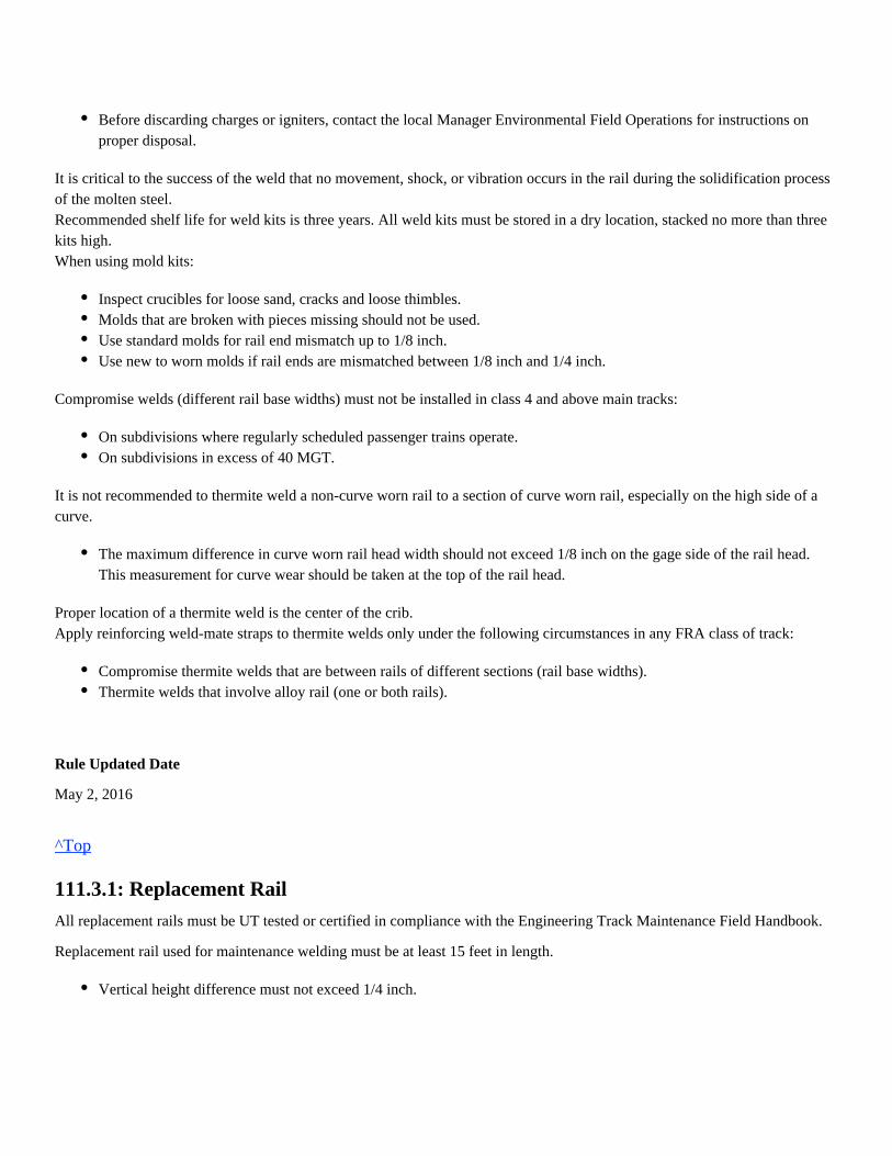
It is critical to the success of the weld that no movement, shock, or vibration occurs in the rail during the solidification processof the molten steel.Recommended shelf life for weld kits is three years. All weld kits must be stored in a dry location, stacked no more than threekits high.When using mold kits:
Compromise welds (different rail base widths) must not be installed in class 4 and above main tracks:
It is not recommended to thermite weld a non-curve worn rail to a section of curve worn rail, especially on the high side of acurve.
Proper location of a thermite weld is the center of the crib.Apply reinforcing weld-mate straps to thermite welds only under the following circumstances in any FRA class of track:
Rule Updated Date
May 2, 2016
^Top
111.3.1: Replacement Rail
All replacement rails must be UT tested or certified in compliance with the Engineering Track Maintenance Field Handbook.
Replacement rail used for maintenance welding must be at least 15 feet in length.
Before discarding charges or igniters, contact the local Manager Environmental Field Operations for instructions onproper disposal.
Inspect crucibles for loose sand, cracks and loose thimbles.Molds that are broken with pieces missing should not be used.Use standard molds for rail end mismatch up to 1/8 inch.Use new to worn molds if rail ends are mismatched between 1/8 inch and 1/4 inch.
On subdivisions where regularly scheduled passenger trains operate.On subdivisions in excess of 40 MGT.
The maximum difference in curve worn rail head width should not exceed 1/8 inch on the gage side of the rail head.This measurement for curve wear should be taken at the top of the rail head.
Compromise thermite welds that are between rails of different sections (rail base widths).Thermite welds that involve alloy rail (one or both rails).
Vertical height difference must not exceed 1/4 inch.
Use a compromise/transition rail on 6 inch base rail when rail end mismatch exceeds 1/4 inch on main track and sidings.
Torch cut rail ends must have at least 2 inches removed with a rail saw.If a rail end is ground down to eliminate mismatch, ground portion must be cut out or replacement rail installed on main trackprior to thermite welding. Rail ends must be square to get proper crown.
Rule Updated Date
May 2, 2016
^Top
111.4: Weather Restrictions
When severe temperatures and weather conditions are present, observe the following welding restrictions: 1. Do not make thermite welds on alloy rail when the rail temperature is below 32° F. 2. Do not make thermite welds on non-alloy rail when the rail temperature falls below 5° F. 3. When rail temperature is below 40º F, or in windy conditions, thermite weld must be covered immediately after shearing with a cooling cap or welding blanket until the weld cools to below 700º F., to prevent weld from cooling too quickly. 4. During rain, sleet, snow or mist;light
Take the following measures to prevent moisture from entering the mold, crucible or welding charge:
5. Before applying molds, use a rail thermometer or pyrometer to check the rail temperature. If the rail temperature is below 35° F, warm the rails as follows:
Rule Updated Date
May 2, 2016
Do not begin the welding process unless properly protected from the wet weather.If the thermite weld process is already in progress, protect the weld from excessive moisture or stop the weldingoperation.
Use of a welding tent with a solid top is allowed to prevent moisture from entering the molds and crucible.Use of an umbrella is allowed from entering molds and crucible.only if moisture can be entirely preventedEnsure that rain, sleet, snow, or mist does not cool the rail placing the weld in tension as the rail contracts.Use a rail puller, when conditions require, to prevent rail movement.During takedown, all welding mold remnants and slag must be placed to eliminate all hazards including slip, tripand fall hazard.
Heat 30 inches to 36 inches from the end of each rail.Raise the rail temperature to between 90° F and 110° F.(This is to add supplemental heat and remove surface condensation)
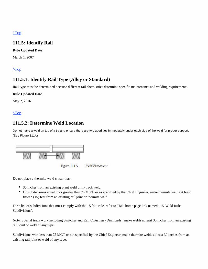
^Top
111.5: Identify Rail
Rule Updated Date
March 1, 2007
^Top
111.5.1: Identify Rail Type (Alloy or Standard)
Rail type must be determined because different rail chemistries determine specific maintenance and welding requirements.
Rule Updated Date
May 2, 2016
^Top
111.5.2: Determine Weld Location
Do not make a weld on top of a tie and ensure there are two good ties immediately under each side of the weld for proper support.
(See Figure 111A)
Do not place a thermite weld closer than:
For a list of subdivisions that must comply with the 15 foot rule, refer to TMP home page link named: '15' Weld RuleSubdivisions'. Note: Special track work including Switches and Rail Crossings (Diamonds), make welds at least 30 inches from an existingrail joint or weld of any type.
Subdivisions with less than 75 MGT or not specified by the Chief Engineer, make thermite welds at least 30 inches from anexisting rail joint or weld of any type.
30 inches from an existing plant weld or in-track weld.On subdivisions equal to or greater than 75 MGT, or as specified by the Chief Engineer, make thermite welds at leastfifteen (15) feet from an existing rail joint or thermite weld.
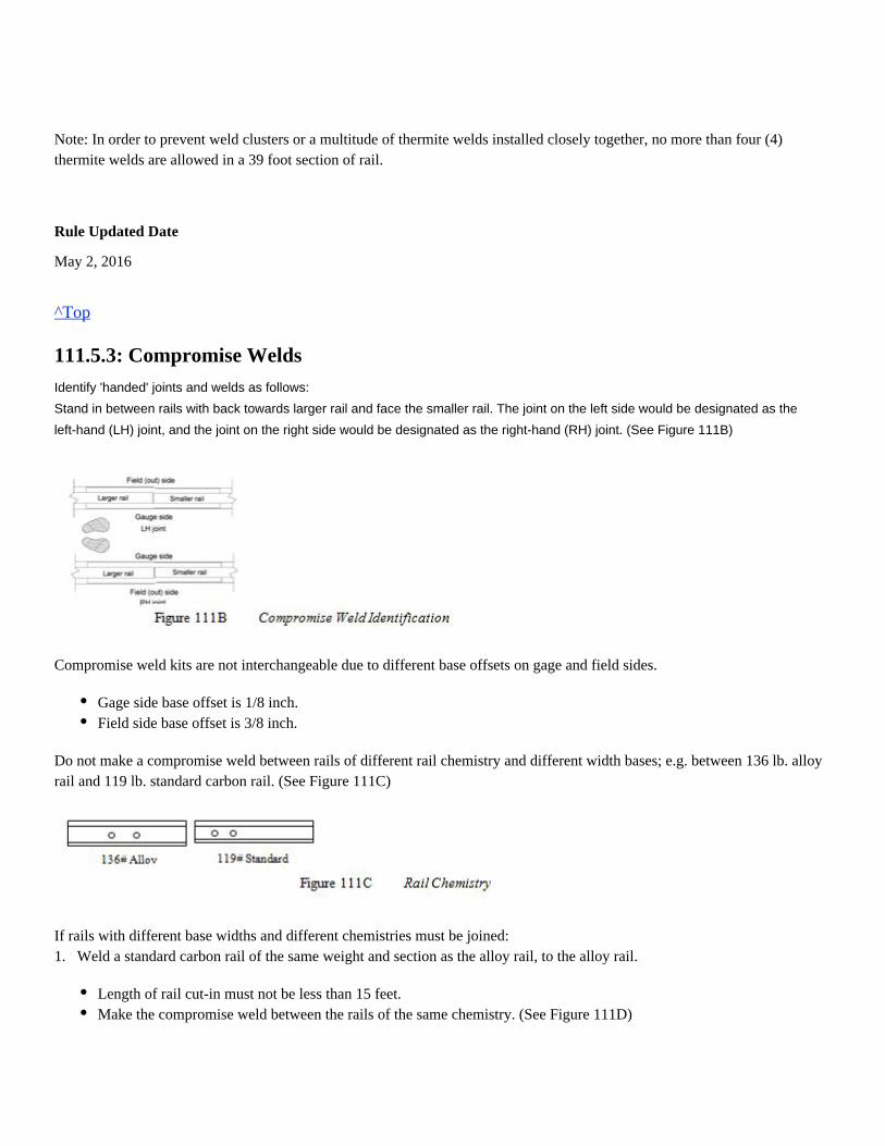
Note: In order to prevent weld clusters or a multitude of thermite welds installed closely together, no more than four (4)thermite welds are allowed in a 39 foot section of rail.
Rule Updated Date
May 2, 2016
^Top
111.5.3: Compromise Welds
Identify 'handed' joints and welds as follows:
Stand in between rails with back towards larger rail and face the smaller rail. The joint on the left side would be designated as the
left-hand (LH) joint, and the joint on the right side would be designated as the right-hand (RH) joint. (See Figure 111B)
Compromise weld kits are not interchangeable due to different base offsets on gage and field sides.
Do not make a compromise weld between rails of different rail chemistry and different width bases; e.g. between 136 lb. alloyrail and 119 lb. standard carbon rail. (See Figure 111C)
If rails with different base widths and different chemistries must be joined:1. Weld a standard carbon rail of the same weight and section as the alloy rail, to the alloy rail.
Gage side base offset is 1/8 inch.Field side base offset is 3/8 inch.
Length of rail cut-in must not be less than 15 feet.Make the compromise weld between the rails of the same chemistry. (See Figure 111D)
Compromise welds on opposite rails should be made within the same crib.
Rule Updated Date
May 2, 2016
^Top
111.6: Compromise/Transition Rail
Use compromise/transition rails when required to reduce or eliminate the use of compromise thermite welds on main track andsidings.(See Figure 111E)Standards drawings are available online in the Engineering Department web page – Procedures and Standards.
Rule Updated Date
May 2, 2016
^Top
111.7: Speed Restrictions - Alloy Rail
For all thermite welds involving alloy rail:
Rule Updated Date
May 2, 2016
^Top
111.8: Eliminate Bolt Holes
Eliminate bolt holes on thermite welds as follows:
1. On thermite welds that require weld-mate straps, eliminate:
a. Bolt holes with centers closer than 8 inches from the rail ends being welded. b. Holes not needed to install the weld-mate strap. 2. On thermite welds that do not require the use of weld-mate straps, eliminate all holes with centers closer than 6 inchesfrom the rail ends being welded.
Rule Updated Date
May 2, 2016
^Top
111.9: Reference Marks
the Engineering Track Maintenance Field HandbookApply reference marks before cutting rail or removing joint bars as outlined in
Section 7.0 Track Buckling Prevention Guidelines.
Rule Updated Date
May 2, 2016
1.
2.
Restrict speed to a maximum of 30 mph for a minimum of 24 hours after installation.
Do not remove speed restriction until all thermite welds in Class 3 and above tracks are inspected and protected byweld-mate straps.
This includes bond wire holes drilled by Signal Maintainers.
^Top
111.10: Remove Defects
Refer to Engineering Track Maintenance Field Handbook for rail defect remediation matrix. (Section 4.0 Rail and Joints) Replacement rail is required when more than one defect of any kind is detected within the same 39-foot length of rail in thesame test. (Except for bolt hole crack defects) When rail detector cars find a defect in a weld, do the following:
When defects previously marked by detector car personnel are repaired, the entire defect must be removed and each railvisually inspected before installing a thermite weld.
1.
2.
In a plant weld, cut out the defect by removing a 1-1/2 inch section of rail, 3/4 inch each direction from center of weld.(See Figure 111F)
In a thermite weld, cut out the defect by removing a 2-3/4 inch section of rail, at least 1-3/8 inches each direction fromcenter of weld.(See Figure 111F)
If rail is not cut and marks are not visible, rail must be re-tested.If rail is not cut and marks are visible, cut on outside of marks.(See Figure 111G)
Rule Updated Date
May 2, 2016
^Top
111.11: Torch Cut Rail
Anytime rail is cut using a torch, do the following:
2. If a rail saw is not used to square the torch cut rail end within 15 minutes after the torch cut is made, an additional 2 inches of rail must be removed from the rail end to get past the thermal crack growth.
Rule Updated Date
If rail was previously cut and no marks are visible, remove 1-3/8 inch from each end.(See Figure 111H)
1. Use a rail saw to trim the torch cut rail end square immediately after the torch cut is made to eliminate the growth of deepthermal heat cracks.
All indication of torch cut must be removed.
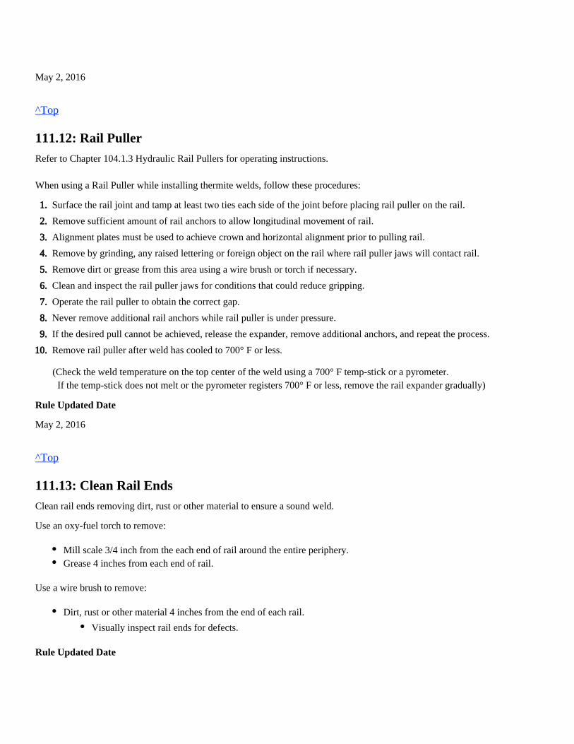
May 2, 2016
^Top
111.12: Rail Puller
Refer to Chapter 104.1.3 Hydraulic Rail Pullers for operating instructions. When using a Rail Puller while installing thermite welds, follow these procedures:
(Check the weld temperature on the top center of the weld using a 700° F temp-stick or a pyrometer. If the temp-stick does not melt or the pyrometer registers 700° F or less, remove the rail expander gradually)
Rule Updated Date
May 2, 2016
^Top
111.13: Clean Rail Ends
Clean rail ends removing dirt, rust or other material to ensure a sound weld.
Use an oxy-fuel torch to remove:
Use a wire brush to remove:
Rule Updated Date
1.
2.
3.
4.
5.
6.
7.
8.
9.
10.
Surface the rail joint and tamp at least two ties each side of the joint before placing rail puller on the rail.
Remove sufficient amount of rail anchors to allow longitudinal movement of rail.
Alignment plates must be used to achieve crown and horizontal alignment prior to pulling rail.
Remove by grinding, any raised lettering or foreign object on the rail where rail puller jaws will contact rail.
Remove dirt or grease from this area using a wire brush or torch if necessary.
Clean and inspect the rail puller jaws for conditions that could reduce gripping.
Operate the rail puller to obtain the correct gap.
Never remove additional rail anchors while rail puller is under pressure.
If the desired pull cannot be achieved, release the expander, remove additional anchors, and repeat the process.
Remove rail puller after weld has cooled to 700° F or less.
Mill scale 3/4 inch from the each end of rail around the entire periphery.Grease 4 inches from each end of rail.
Dirt, rust or other material 4 inches from the end of each rail.
Visually inspect rail ends for defects.
May 2, 2016
^Top
111.14: Rail End Gap - Standard (1-inch) and Wide Gap Weld (WGW)
The required gap must be achieved to within 1/16 inch before thermite welding. Improper gap width results in improperpreheating or lack of sufficient weld material. Rails must be cut square to within 1/16 inch perpendicular from the top to the bottom and from the gage side to the field side.
When thermite welding, create the proper gap as follows:
Rule Updated Date
May 2, 2016
^Top
111.15: Alignment System
Use of rail alignment plates is required when installing thermite welds. Exception: Alignment wedges where rail alignment plates fail to work properly such as switches.must only be usedNote: Steel wedges must be kept in safe condition and metal flow dressed to eliminate cracks and chipping. After dressingwedge, apply an approved protective covering.
Rule Updated Date
May 2, 2016
^Top
111.16: Create Crown - Standard and Wide Gap Weld
Use a 36 inch straightedge to ensure proper crown is established. Use of a taper gauge is required to setup the adjustable typestraightedge and must always be used with a non-adjustable straightedge while crowning rail ends.
To create the proper crown using rail alignment plates, do the following:
Combined deviation between both rails will not exceed 1/8 inch.
1.
2.
Create a 1 inch gap for a standard thermite weld.
Create a 2-3/4 inch gap for a wide gap weld.
1. On wood ties, move tie plates to accommodate rail alignment plates.
Adz ties for proper fit of alignment plates if necessary.
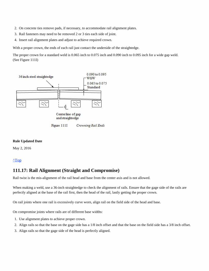
With a proper crown, the ends of each rail just contact the underside of the straightedge.
The proper crown for a standard weld is 0.065 inch to 0.075 inch and 0.090 inch to 0.095 inch for a wide gap weld.(See Figure 111I)
Rule Updated Date
May 2, 2016
^Top
111.17: Rail Alignment (Straight and Compromise)
Rail twist is the mis-alignment of the rail head and base from the center axis and is not allowed. When making a weld, use a 36-inch straightedge to check the alignment of rails. Ensure that the gage side of the rails areperfectly aligned at the base of the rail first, then the head of the rail, lastly getting the proper crown. On rail joints where one rail is excessively curve worn, align rail on the field side of the head and base. On compromise joints where rails are of different base widths:
1.
2.
3.
4.
On concrete ties remove pads, if necessary, to accommodate rail alignment plates.
Rail fasteners may need to be removed 2 or 3 ties each side of joint.
Insert rail alignment plates and adjust to achieve required crown.
1.
2.
3.
Use alignment plates to achieve proper crown.
Align rails so that the base on the gage side has a 1/8 inch offset and that the base on the field side has a 3/8 inch offset.
Align rails so that the gage side of the head is perfectly aligned.
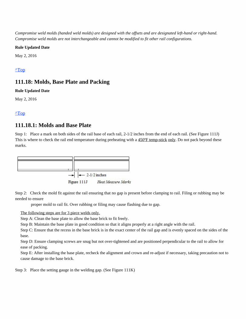
Compromise weld molds (handed weld molds) are designed with the offsets and are designated left-hand or right-hand.Compromise weld molds are not interchangeable and cannot be modified to fit other rail configurations.
Rule Updated Date
May 2, 2016
^Top
111.18: Molds, Base Plate and Packing
Rule Updated Date
May 2, 2016
^Top
111.18.1: Molds and Base Plate
Step 1: Place a mark on both sides of the rail base of each rail, 2-1/2 inches from the end of each rail. (See Figure 111J)This is where to check the rail end temperature during preheating with a . Do not pack beyond these450ºF temp-stick onlymarks.
Step 2: Check the mold fit against the rail ensuring that no gap is present before clamping to rail. Filing or rubbing may beneeded to ensure proper mold to rail fit. Over rubbing or filing may cause flashing due to gap.
The following steps are for 3 piece welds only.Step A: Clean the base plate to allow the base brick to fit freely.Step B: Maintain the base plate in good condition so that it aligns properly at a right angle with the rail.Step C: Ensure that the recess in the base brick is in the exact center of the rail gap and is evenly spaced on the sides of thebase.Step D: Ensure clamping screws are snug but not over-tightened and are positioned perpendicular to the rail to allow forease of packing.Step E: After installing the base plate, recheck the alignment and crown and re-adjust if necessary, taking precaution not tocause damage to the base brick.
Step 3: Place the setting gauge in the welding gap. (See Figure 111K)
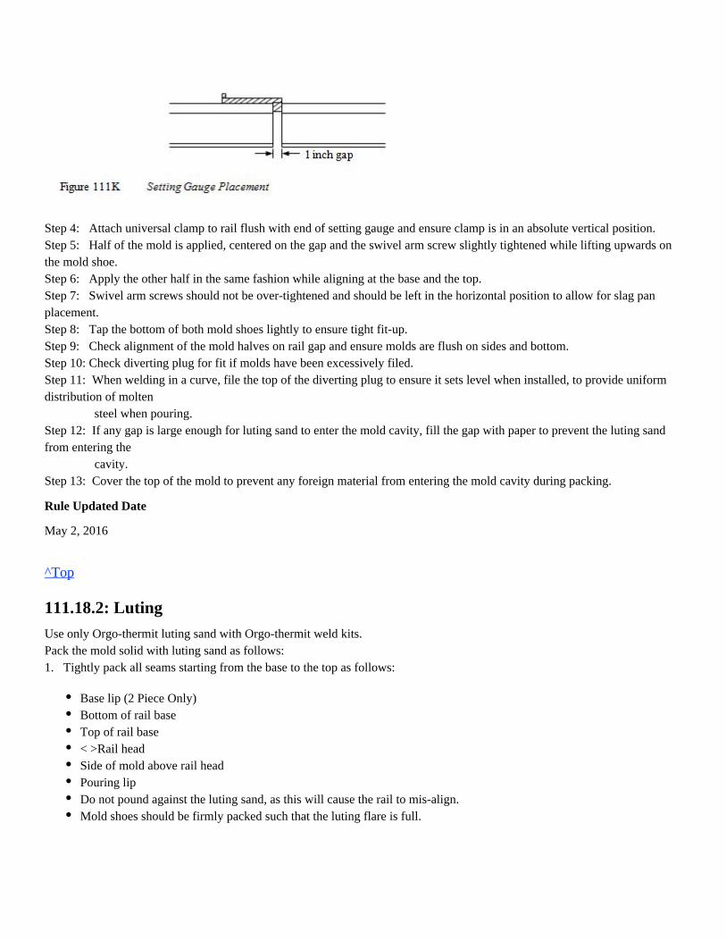
Step 4: Attach universal clamp to rail flush with end of setting gauge and ensure clamp is in an absolute vertical position.Step 5: Half of the mold is applied, centered on the gap and the swivel arm screw slightly tightened while lifting upwards onthe mold shoe.Step 6: Apply the other half in the same fashion while aligning at the base and the top.Step 7: Swivel arm screws should not be over-tightened and should be left in the horizontal position to allow for slag panplacement.Step 8: Tap the bottom of both mold shoes lightly to ensure tight fit-up.Step 9: Check alignment of the mold halves on rail gap and ensure molds are flush on sides and bottom.Step 10: Check diverting plug for fit if molds have been excessively filed.Step 11: When welding in a curve, file the top of the diverting plug to ensure it sets level when installed, to provide uniformdistribution of molten steel when pouring.Step 12: If any gap is large enough for luting sand to enter the mold cavity, fill the gap with paper to prevent the luting sandfrom entering the cavity.Step 13: Cover the top of the mold to prevent any foreign material from entering the mold cavity during packing.
Rule Updated Date
May 2, 2016
^Top
111.18.2: Luting
Use only Orgo-thermit luting sand with Orgo-thermit weld kits.Pack the mold solid with luting sand as follows:1. Tightly pack all seams starting from the base to the top as follows:
Base lip (2 Piece Only)Bottom of rail baseTop of rail base< >Rail headSide of mold above rail headPouring lipDo not pound against the luting sand, as this will cause the rail to mis-align.Mold shoes should be firmly packed such that the luting flare is full.
2. Ensure packing sand does not enter the mold cavity.3. If luting sand does enter the mold cavity, disassemble the mold, remove the sand mixture and repack the mold.4. Position slag pans onto mold shoe lugs prior to beginning preheat.
Plan the packing stage so that the preheating cycle can begin immediately after packing is complete. Once the packing iscomplete, do not allow the finished mold to sit more than 10 minutes before preheating
Rule Updated Date
May 2, 2016
^Top
111.19: Preheating Procedures
Before preheating, ensure you are familiar with and have been properly trained in the operation of that equipment.
Use of a stopwatch is required when thermite welding for preheating, tap and take down times.
Prior to preheating, do the following:
Rule Updated Date
May 2, 2016
^Top
111.19.1: Use of Oxy-Propane Equipment
Use a Hesa SKV-5 preheat burner and Hesa burner stem, Victor HD310C torch body or equivalent with the Railtech flat heador Victor TWN-5 rectangular torch tip.
Dry slag pans with preheating torch to ensure all moisture is removed.
Torch must be level and torch height checked prior to preheating.Place burner saddle assembly on the universal clamp.Turn the saddle adjustment knobs to center the burner head in the gap.Align the burner head so it is vertically straight and not pointing toward the gage or field side of the railhead.After pre-aligning the burner, remove the burner saddle assembly from the universal clamp.
Pressure settings may vary for each set of equipment and should be adjusted accordingly.Torch mounted in-line gauges must be used and working properly to verify pressure settings on every weld and will beplaced between torch handle and flashback arrestors.Extreme pressure variances of 15 psi or more between cylinder regulator and in-line gauge indicates a restriction orproblem, and must be corrected.Ensure there is sufficient oxygen and fuel-gas in cylinders to complete the preheating.
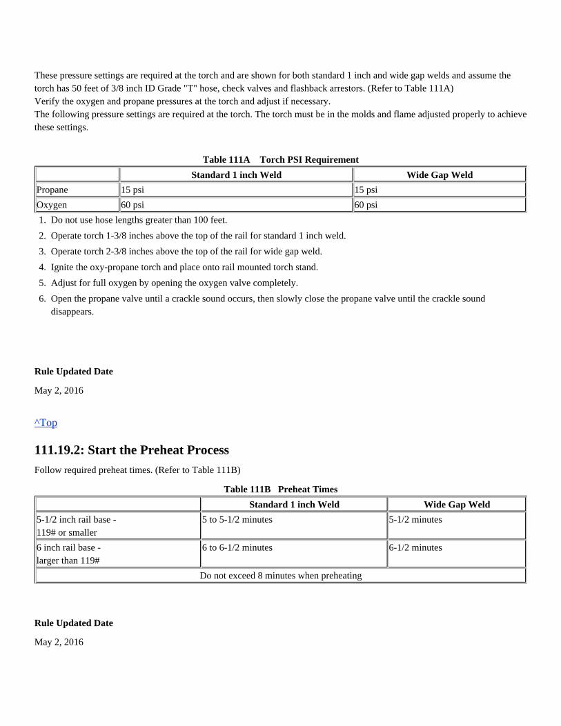
These pressure settings are required at the torch and are shown for both standard 1 inch and wide gap welds and assume thetorch has 50 feet of 3/8 inch ID Grade "T" hose, check valves and flashback arrestors. (Refer to Table 111A)Verify the oxygen and propane pressures at the torch and adjust if necessary.The following pressure settings are required at the torch. The torch must be in the molds and flame adjusted properly to achievethese settings.
Table 111A Torch PSI Requirement
Standard 1 inch Weld Wide Gap Weld
Propane 15 psi 15 psi
Oxygen 60 psi 60 psi
Rule Updated Date
May 2, 2016
^Top
111.19.2: Start the Preheat Process
Follow required preheat times. (Refer to Table 111B)
Table 111B Preheat Times
Standard 1 inch Weld Wide Gap Weld
5-1/2 inch rail base -119# or smaller
5 to 5-1/2 minutes 5-1/2 minutes
6 inch rail base -larger than 119#
6 to 6-1/2 minutes 6-1/2 minutes
Do not exceed 8 minutes when preheating
Rule Updated Date
May 2, 2016
1.
2.
3.
4.
5.
6.
Do not use hose lengths greater than 100 feet.
Operate torch 1-3/8 inches above the top of the rail for standard 1 inch weld.
Operate torch 2-3/8 inches above the top of the rail for wide gap weld.
Ignite the oxy-propane torch and place onto rail mounted torch stand.
Adjust for full oxygen by opening the oxygen valve completely.
Open the propane valve until a crackle sound occurs, then slowly close the propane valve until the crackle sounddisappears.
^Top
111.19.3: Monitor Preheating Process
Wear the required PPE when monitoring the preheat process.
- If rail ends appear to be getting too hot, cool the flame by increasing the propane flow at the torch handle.
If rail end melting occurs: Stop, tear down molds, re-cut rail ends and start over.Preheating is completed when the required preheat time has been achieved the rail base is 450° F on all four sides. (At theandmarks measured 2-1/2 inches from the end of rails with a ). temp-stick only Do not use a pyrometer to check rail base
.temperature
Rule Updated Date
May 2, 2016
^Top
111.19.4: Railtech Propane/Compressed Air Rail Preheater (Model 03800B)
To setup and operate the Propane/Compressed Air Rail Preheater, follow these instructions. (Refer to equipment manual forcomplete operating instructions and safety precautions)
Ensure the torch is centered and straight..The employee igniting and placing the torch must observe the entire preheating of the rail ends
Ensure the rail ends do not melt.Ensure the rail ends and molds heat evenly to prevent improper fusion and internal cracks that result from unevencooling.Ensure that the web glows a bright red/orange with no signs of sweating or melting.
Ensure the rail head and base glow a dull red and have no black areas.After removing the torch, observe the true color of the rail ends. If they do not hold their color, replace the torch andcontinue preheating.
1.
2.
3.
4.
5.
6.
7.
8.
Connect the stainless steel flex line from the regulator on the hydraulic propane unit to the propane cylinder. Make surethat all fittings are tight.
Connect the hydraulic hoses from the power source to the hydraulic propane unit.
Align the inox-heating nozzle so that the flat piece of the nozzle is no higher than the top of the inside of the mold wherethe diverter plug fits. The nozzle tip must be aligned straight up and down perpendicular to the rail.
Prior to starting the preheating unit, tilt the nozzle up slightly to help start the flame.
Ensure that there is no pressure on the diaphragm by turning the pressure adjusting screw counter-clockwise on thepropane regulator.
Operate hydraulic system at 10 GPM @ 2000 psi.
Open the hydraulic control valve on the preheater to engage the blower unit.
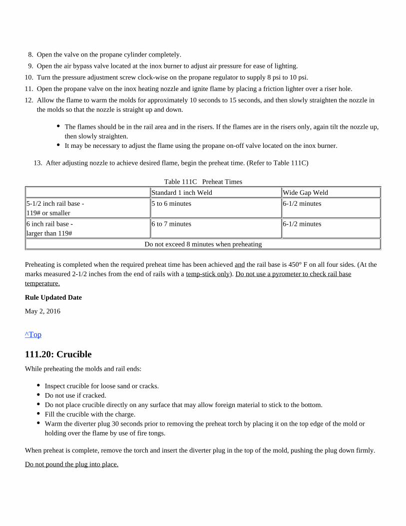
13. After adjusting nozzle to achieve desired flame, begin the preheat time. (Refer to Table 111C)
Table 111C Preheat Times
Standard 1 inch Weld Wide Gap Weld
5-1/2 inch rail base -119# or smaller
5 to 6 minutes 6-1/2 minutes
6 inch rail base -larger than 119#
6 to 7 minutes 6-1/2 minutes
Do not exceed 8 minutes when preheating
Preheating is completed when the required preheat time has been achieved the rail base is 450° F on all four sides. (At theandmarks measured 2-1/2 inches from the end of rails with a ). temp-stick only Do not use a pyrometer to check rail basetemperature.
Rule Updated Date
May 2, 2016
^Top
111.20: Crucible
While preheating the molds and rail ends:
When preheat is complete, remove the torch and insert the diverter plug in the top of the mold, pushing the plug down firmly.
Do not pound the plug into place.
8.
9.
10.
11.
12.
Open the valve on the propane cylinder completely.
Open the air bypass valve located at the inox burner to adjust air pressure for ease of lighting.
Turn the pressure adjustment screw clock-wise on the propane regulator to supply 8 psi to 10 psi.
Open the propane valve on the inox heating nozzle and ignite flame by placing a friction lighter over a riser hole.
Allow the flame to warm the molds for approximately 10 seconds to 15 seconds, and then slowly straighten the nozzle inthe molds so that the nozzle is straight up and down.
The flames should be in the rail area and in the risers. If the flames are in the risers only, again tilt the nozzle up,then slowly straighten.It may be necessary to adjust the flame using the propane on-off valve located on the inox burner.
Inspect crucible for loose sand or cracks.Do not use if cracked.Do not place crucible directly on any surface that may allow foreign material to stick to the bottom.Fill the crucible with the charge.Warm the diverter plug 30 seconds prior to removing the preheat torch by placing it on the top edge of the mold orholding over the flame by use of fire tongs.
Note: The diverter plug allows the molten steel to flow into the mold properly, filling the mold evenly.Place the crucible onto the molds and center over diverter plug, using the two large riser holes as a guide.
Rule Updated Date
May 2, 2016
^Top
111.21: Igniting and Pouring
To ignite the charge:
Tap Time: The time it takes after igniting the charge for the molten steel to flow out of the crucible.
Hot metal or slag coming in contact with moisture can cause an explosion. When the thermite weld is pouring, protect yourselfand others from:
After igniting the charge:
If a leak develops in the mold, do not attempt to stop the leak.
Rule Updated Date
May 2, 2016
^Top
111.22: Minimum Take Down Times
Follow minimum takedown times. (Refer to Table 111D)Step 1. Remove crucible with proper tool and place at a safe dry location.
Step 2. Remove slag pans and place at a safe dry location.
When using a stick igniter, light the igniter by touching it on the inside of the riser hole.Place the stick igniter in the charge within the crucible to a depth of and step back. (Do not over insert)1-inchDo not use an oxy-fuel torch to ignite the stick igniter or thermite weld charge.
Acceptable tap time is 15 seconds to 35 seconds.If tap time is less than 15 seconds or more than 35 seconds, the weld must be considered defective and removed fromtrack.
Coming in contact with hot molten steel, as high as 5,000° F.Bright light from the thermite reaction-protect your eyes.
Stand back at least 15 feet while the molten steel pours into the mold.
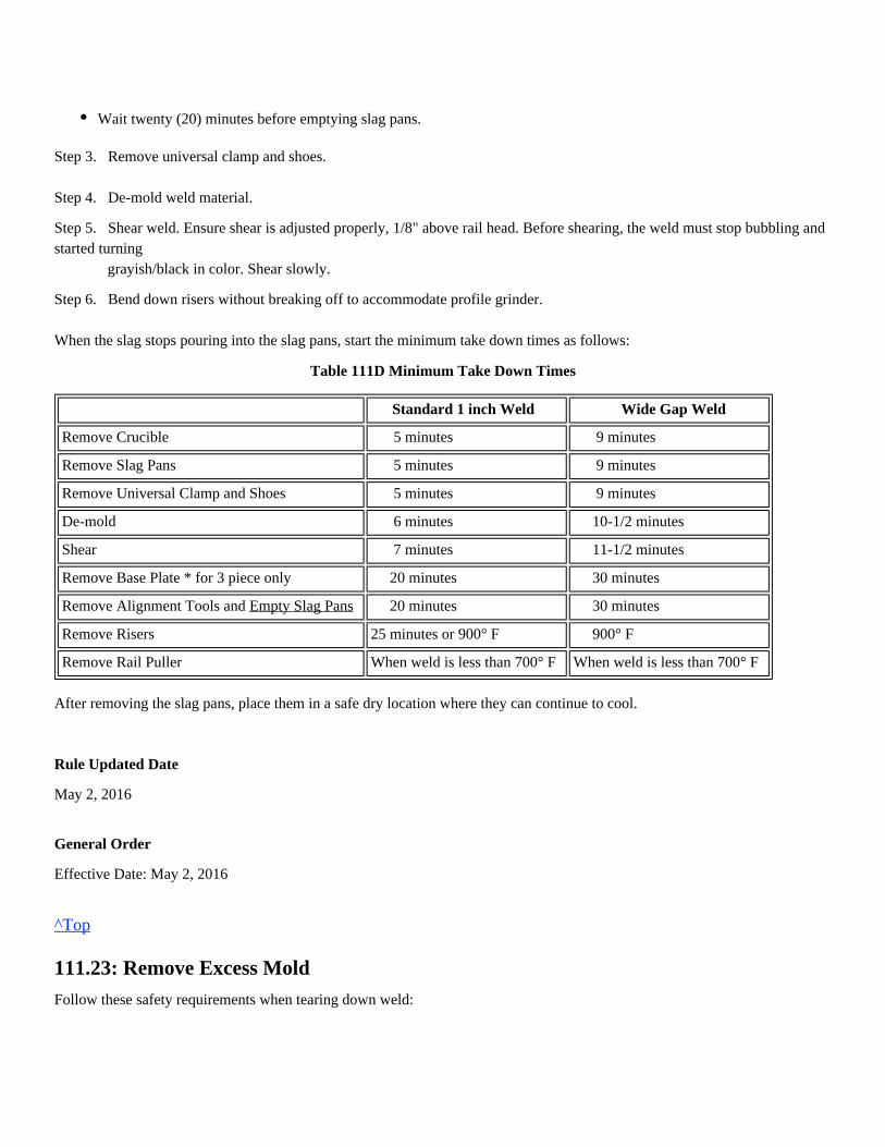
Step 3. Remove universal clamp and shoes.
Step 4. De-mold weld material.
Step 5. Shear weld. Ensure shear is adjusted properly, 1/8" above rail head. Before shearing, the weld must stop bubbling andstarted turning grayish/black in color. Shear slowly.
Step 6. Bend down risers without breaking off to accommodate profile grinder.
When the slag stops pouring into the slag pans, start the minimum take down times as follows:
Table 111D Minimum Take Down Times
Standard 1 inch Weld Wide Gap Weld
Remove Crucible 5 minutes 9 minutes
Remove Slag Pans 5 minutes 9 minutes
Remove Universal Clamp and Shoes 5 minutes 9 minutes
De-mold 6 minutes 10-1/2 minutes
Shear 7 minutes 11-1/2 minutes
Remove Base Plate * for 3 piece only 20 minutes 30 minutes
Remove Alignment Tools and Empty Slag Pans 20 minutes 30 minutes
Remove Risers 25 minutes or 900° F 900° F
Remove Rail Puller When weld is less than 700° F When weld is less than 700° F
After removing the slag pans, place them in a safe dry location where they can continue to cool.
Rule Updated Date
May 2, 2016
General Order
Effective Date: May 2, 2016
^Top
111.23: Remove Excess Mold
Follow these safety requirements when tearing down weld:
Wait twenty (20) minutes before emptying slag pans.
1.
Rule Updated Date
May 2, 2016
^Top
111.24: Rough Grinding
Rough grinding of the rail head portion of the thermite weld can be performed after shearing. Rough grinding of the runningsurface of the rail shall be performed with a surface grinder and is completed when the excess weld material is reduced toapproximately 30 thousandths (0.030) of an inch.When the surface of the weld is above 700° F, it is permitted to "blue" the weld.Remove alignment plates and base plate in accordance with take down times.Remove risers by lightly tapping downward toward ground.Apply rail fasteners and ensure ties are tamped solid under the weld.
Train traffic or heavy work equipment (spikers, tampers, etc.) must not be allowed over a thermite weld until the weld hascooled below 700° F.
Rule Updated Date
May 2, 2016
^Top
111.25: Finish Grinding
Using an 8' x 1' straight stone grinder:
Thermite welds must not have the weld collar ground as to reduce the amount of metal from the web area.
Removing metal from the weld collar to accommodate joint bars is prohibited.
1.
2.
3.
4.
5.
Wrap-around face shield with goggles or safety glasses must be worn when removing the mold and cleaning the weld, or
Mono-goggle XTR with safety glasses can be used as an alternative.
Protect yourself from hot metal fragments and sand.
Do not discard the hot slag where someone could step on it, or where it could start a grass fire.
Do not discard hot slag on wet soil, snow or throw into water.
Use a hydraulic tamper if available.
Taper and remove sharp edges from the teardrop under rail head (See Figure 111L).Grind the risers flush with weld collar.Do not grind into the collar.Do not grind into the parent metal.If inclusions are visible and cannot be removed by grinding, the weld must be removed.
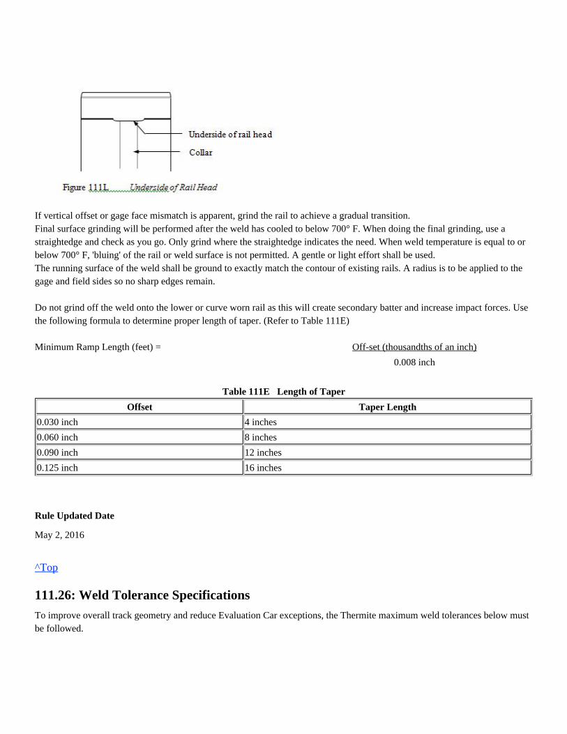
If vertical offset or gage face mismatch is apparent, grind the rail to achieve a gradual transition.Final surface grinding will be performed after the weld has cooled to below 700° F. When doing the final grinding, use astraightedge and check as you go. Only grind where the straightedge indicates the need. When weld temperature is equal to orbelow 700° F, 'bluing' of the rail or weld surface is not permitted. A gentle or light effort shall be used.The running surface of the weld shall be ground to exactly match the contour of existing rails. A radius is to be applied to thegage and field sides so no sharp edges remain. Do not grind off the weld onto the lower or curve worn rail as this will create secondary batter and increase impact forces. Usethe following formula to determine proper length of taper. (Refer to Table 111E) Minimum Ramp Length (feet) = Off-set (thousandths of an inch)
0.008 inch
Table 111E Length of Taper
Offset Taper Length
0.030 inch 4 inches
0.060 inch 8 inches
0.090 inch 12 inches
0.125 inch 16 inches
Rule Updated Date
May 2, 2016
^Top
111.26: Weld Tolerance Specifications
To improve overall track geometry and reduce Evaluation Car exceptions, the Thermite maximum weld tolerances below mustbe followed.
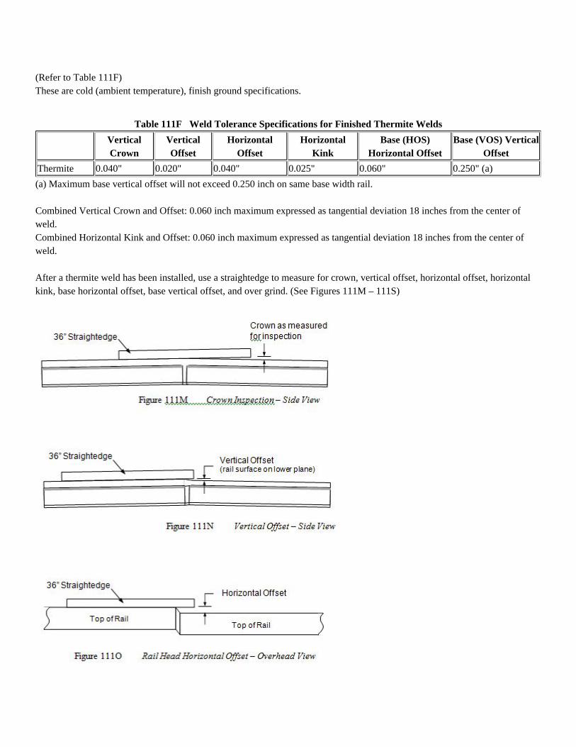
(Refer to Table 111F)These are cold (ambient temperature), finish ground specifications.
Table 111F Weld Tolerance Specifications for Finished Thermite Welds
VerticalCrown
VerticalOffset
HorizontalOffset
HorizontalKink
Base (HOS)Horizontal Offset
Base (VOS) VerticalOffset
Thermite 0.040" 0.020" 0.040" 0.025" 0.060" 0.250" (a)
(a) Maximum base vertical offset will not exceed 0.250 inch on same base width rail.
Combined Vertical Crown and Offset: 0.060 inch maximum expressed as tangential deviation 18 inches from the center ofweld.Combined Horizontal Kink and Offset: 0.060 inch maximum expressed as tangential deviation 18 inches from the center ofweld.
After a thermite weld has been installed, use a straightedge to measure for crown, vertical offset, horizontal offset, horizontalkink, base horizontal offset, base vertical offset, and over grind. (See Figures 111M – 111S)
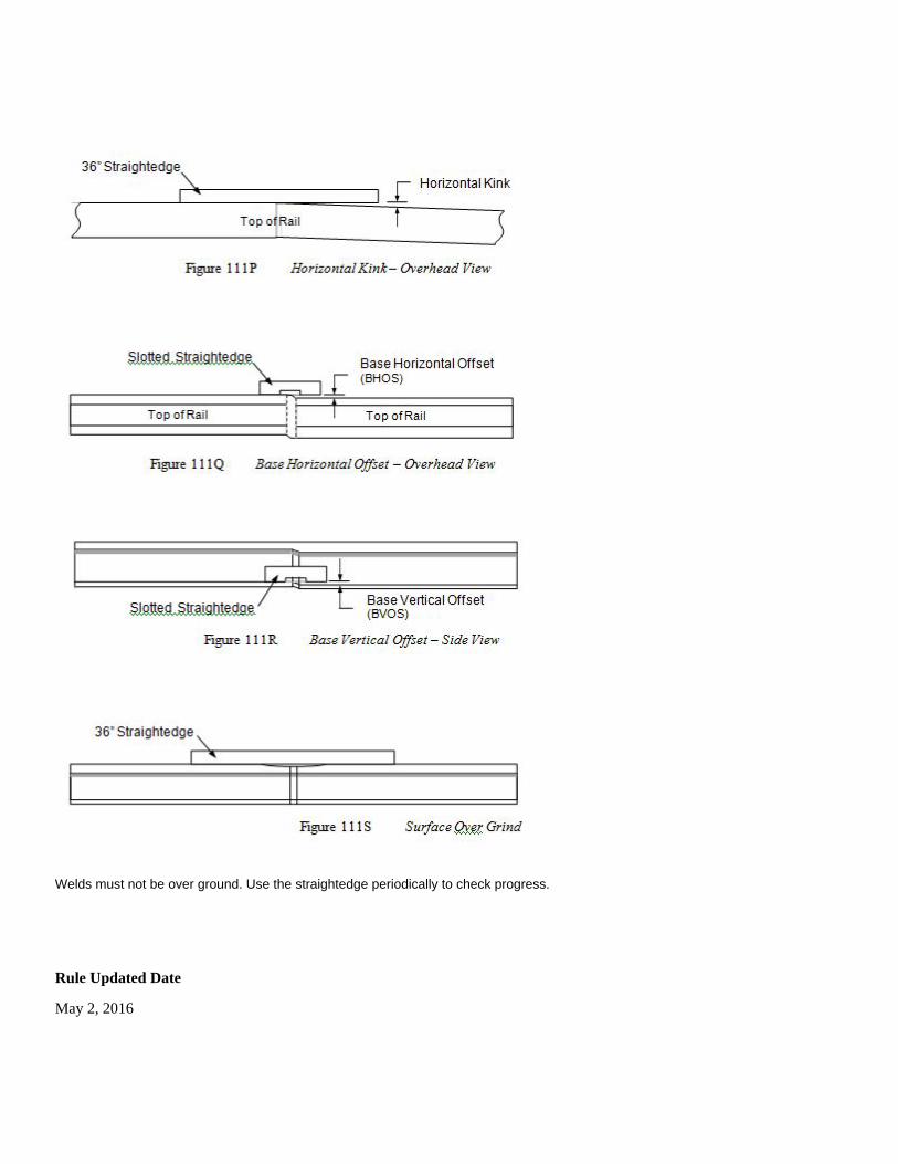
Welds must not be over ground. Use the straightedge periodically to check progress.
Rule Updated Date
May 2, 2016
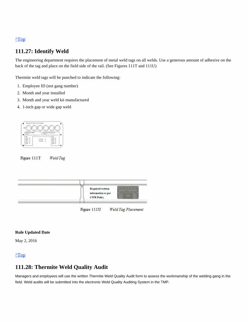
^Top
111.27: Identify Weld
The engineering department requires the placement of metal weld tags on all welds. Use a generous amount of adhesive on theback of the tag and place on the field side of the rail. (See Figures 111T and 111U)
Thermite weld tags will be punched to indicate the following:
Rule Updated Date
May 2, 2016
^Top
111.28: Thermite Weld Quality Audit
Managers and employees will use the written Thermite Weld Quality Audit form to assess the workmanship of the welding gang in the
field. Weld audits will be submitted into the electronic Weld Quality Auditing System in the TMP.
1.
2.
3.
4.
Employee ID (not gang number)
Month and year installed
Month and year weld kit manufactured
1-inch gap or wide gap weld
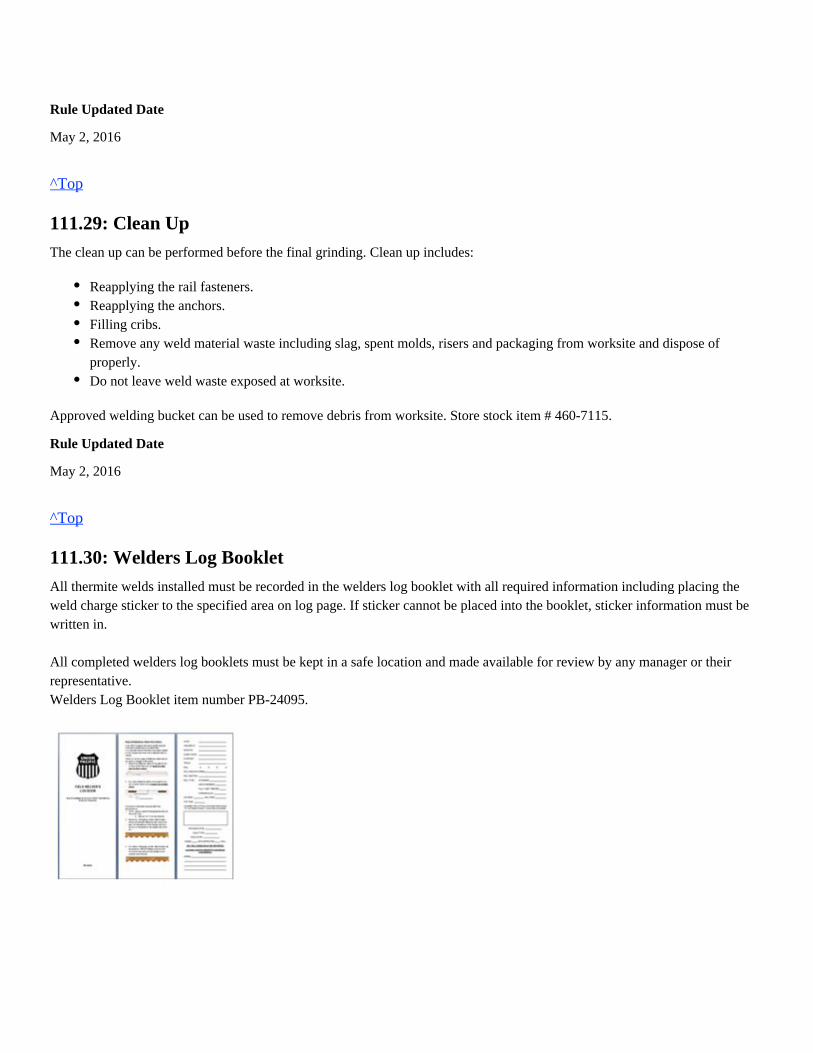
Rule Updated Date
May 2, 2016
^Top
111.29: Clean Up
The clean up can be performed before the final grinding. Clean up includes:
Approved welding bucket can be used to remove debris from worksite. Store stock item # 460-7115.
Rule Updated Date
May 2, 2016
^Top
111.30: Welders Log Booklet
All thermite welds installed must be recorded in the welders log booklet with all required information including placing theweld charge sticker to the specified area on log page. If sticker cannot be placed into the booklet, sticker information must bewritten in.
All completed welders log booklets must be kept in a safe location and made available for review by any manager or theirrepresentative.Welders Log Booklet item number PB-24095.
Reapplying the rail fasteners.Reapplying the anchors.Filling cribs.Remove any weld material waste including slag, spent molds, risers and packaging from worksite and dispose ofproperly.Do not leave weld waste exposed at worksite.
Rule Updated Date
May 2, 2016
^Top
111.31: Thermite Head Repair Weld
Only designated track welding employees who have been trained and qualified are allowed to install thermite head repairwelds.All PPE must be worn as required for any thermite welding procedure.When performing dye-penetrant testing, wear wrap-around face shield with goggles or safety glasses.
Orgo-thermit weld kits are available for 115#/119#, 132#, 133#, 136# and 141# rail. On Orgo-thermit welds, entire rail head is removed by grinding.
Head repair welds use specific weld hardware.
Rule Updated Date
May 2, 2016
^Top
111.31.1: Rail Preparation
1. Do not weld on non-alloy rail when the rail temperature is below 5° F.
2. Remove by grinding, the entire defect within the rail head until the web of rail is exposed to a width of 1-inch only. (entirerail head is removed)
3. Use an oxy-fuel torch and wire brush to clean the rail of any dirt, oil, grease or other contaminants.
Rule Updated Date
May 2, 2016
^Top
111.31.2: Dye Penetrant Testing
Mono-goggle XTR with safety glasses can be used as an alternative.
Warm rail to remove any surface moisture around entire periphery of rail.
Care must be taken not to over grind the notch.Use a file or hand grinder if necessary to remove any sharp edge after defect removal.Depth of cut will vary depending on amount of rail head loss.
Conduct Dye-Penetrant Test on DF type defects (Not required for SSC type defect)
Rule Updated Date
May 2, 2016
^Top
111.31.3: Crowning Rail
Rail must be crowned using a 36 inch straightedge with taper gauge and alignment tools.
Rule Updated Date
May 2, 2016
^Top
111.31.4: Torch Height
Rule Updated Date
May 2, 2016
^Top
111.31.5: Molds and Clamp
1.
2.
3.
4.
5.
6.
7.
8.
9.
Gloves must be worn during the entire process.
Brush the surface of the rail with a wire brush to remove contaminants.
Clean the surface of the rail free of dust and dirt with a piece of cloth.
Spray the cleaner on the surface to remove oil, grease, etc. and wipe with cloth.
Apply the dye penetrant (by spraying) adequately to cover the area to be tested. Allow 3 to 5 minutes for dye to penetrateinto the cracks.
Wipe off the excess penetrant on the surface with a piece of cloth.
Again spray the surface with the cleaner to remove the remnants of the red dye if needed.
Spray the developer evenly on the surface to give a thin even layer. This layer absorbs the penetrant from the cracks andred spots or lines appear on the surface to give a visible indication of the flaws.
The crack if any will be indicated with the red dye absorbed by the white developer.
Remove white developer before proceeding.
Crowning will be 0.050 inch to 0.060 inch.
Pre-set preheat burner height to 3 inches as measured from top of rail.
1. Set mold clamping device and apply molds.
2. Place pouring plug inside mold to check fit (remove plug).3. Cover top of molds before beginning packing to prevent contaminants from entering mold cavity.4. Pack molds working from the bottom up.5. Place slag pans on each side.
Rule Updated Date
May 2, 2016
^Top
111.31.6: Preheating (Oxy-fuel Torch)
1. Preheating using an oxy-fuel torch:2. Both time and temperature requirement must be met to complete preheat stage. (Refer to Table 111G and Table 111H)
Table 111G Pressure Settings
Oxygen Propane
115#/119# 60 psi 15 psi
132#/136# 60 psi 15 psi
133# 60 psi 15 psi
141# 60 psi 15 psi
Table 111H Preheat Time and Temperature
Time Temperature
115#/119# 2-1/2 minutes 250 F
132#/136# 2-1/2 minutes 250 F
133# 2-1/2 minutes 250 F
141# 2-1/2 minutes 250 F
3. In-line gauges are required as specified by UPRR track welding rules to provide accurate preheat when using an oxy-fueltorch.4. When using an oxy-fuel torch, ignite torch before placing into molds, adjust flame and re- adjust pressure settings if needed.5. Adjust (open) propane control valve on torch handle if needed to cool the flame.6. Monitor preheat during entire process to ensure no melting of rail occurs.7. Warm diverter plug during the last 30 seconds of preheat by using the tongs.
Molds may need to be filed / rubbed to ensure a tight fit to rail, especially the area directly under the rail head.Care must be taken to not over file or rub as this may cause flashing.
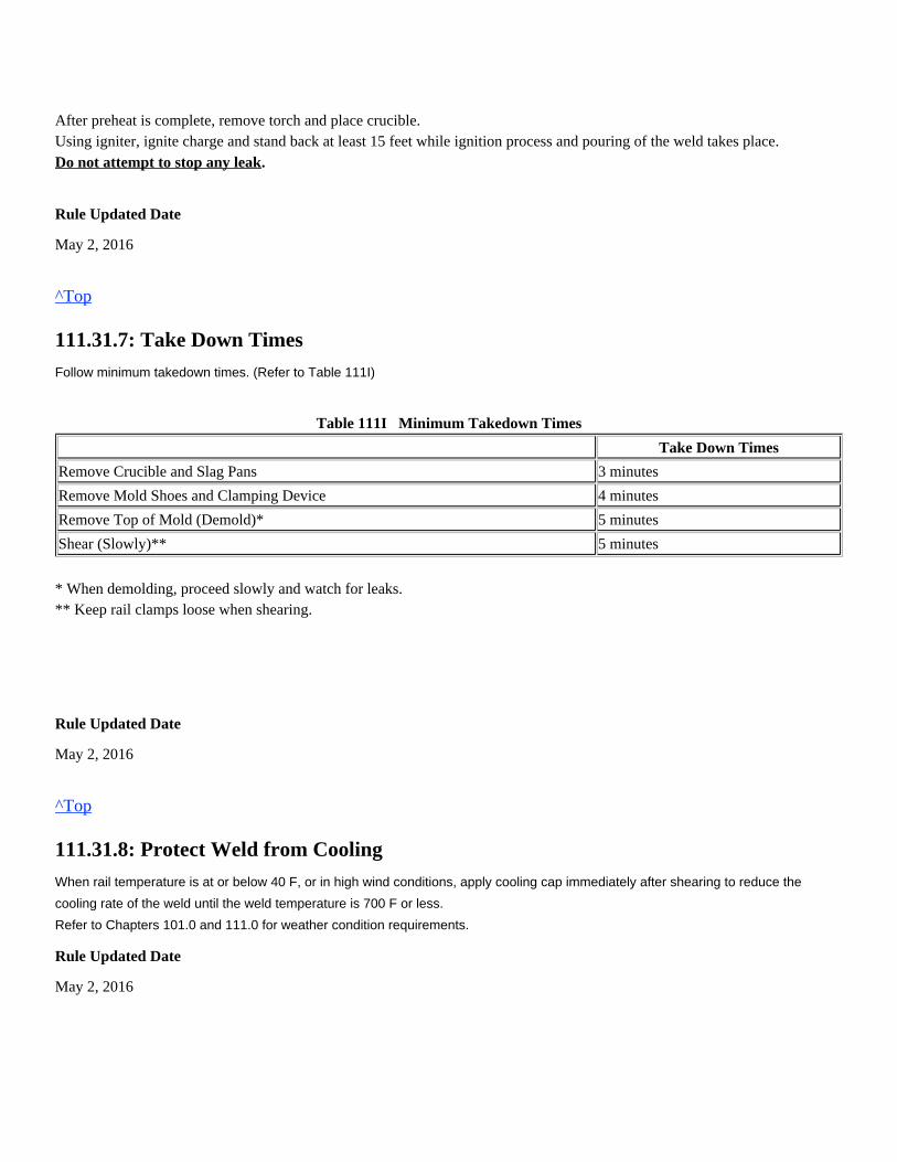
After preheat is complete, remove torch and place crucible.Using igniter, ignite charge and stand back at least 15 feet while ignition process and pouring of the weld takes place.
.Do not attempt to stop any leak
Rule Updated Date
May 2, 2016
^Top
111.31.7: Take Down Times
Follow minimum takedown times. (Refer to Table 111I)
Table 111I Minimum Takedown Times
Take Down Times
Remove Crucible and Slag Pans 3 minutes
Remove Mold Shoes and Clamping Device 4 minutes
Remove Top of Mold (Demold)* 5 minutes
Shear (Slowly)** 5 minutes
* When demolding, proceed slowly and watch for leaks.** Keep rail clamps loose when shearing.
Rule Updated Date
May 2, 2016
^Top
111.31.8: Protect Weld from Cooling
When rail temperature is at or below 40 F, or in high wind conditions, apply cooling cap immediately after shearing to reduce the
cooling rate of the weld until the weld temperature is 700 F or less.
Refer to Chapters 101.0 and 111.0 for weather condition requirements.
Rule Updated Date
May 2, 2016
^Top
111.31.9: Grinding
Rough grind weld until material is reduced to about 0.030 inch in height.Do not finish grind (blend in) while weld temperature is above 700 F. as this will result in a low weld.Do not grind onto the parent steel as this will result in "dipping and batter", unless the need to taper rail due to apparentexisting batter is present that requires tapering to smooth transition.
Empty slag pans and remove crowning device at 20 minutes after the pour is completed.
Finish grinding the weld to match the contour of the existing rail.Any indication of "flashing" under the rail head must be removed by grinding.
All welds will be identified with the standard weld tag green "test" tag for identification.andEnsure weld is accurately entered into the reporting system using the code (OH) for Orgo-thermit head weld
Rule Updated Date
May 2, 2016
^Top
111.31.10: Clean Up
The clean up can be performed before the final grinding. Clean up includes:
Record weld installation information into the welders log book.
Rule Updated Date
This may be apparent on some SSC type defects.
Time begins when last drop of slag flows into slag basin.
Flashing contributes to defect development.
Reapplying the rail fasteners.Reapplying the anchors.Filling cribs.Remove any weld material waste including slag, spent molds, risers and packaging from worksite and dispose ofproperly.
Approved welding bucket can be used to remove debris from worksite. Store stock item # 460-7115.Do not leave weld waste exposed at worksite.
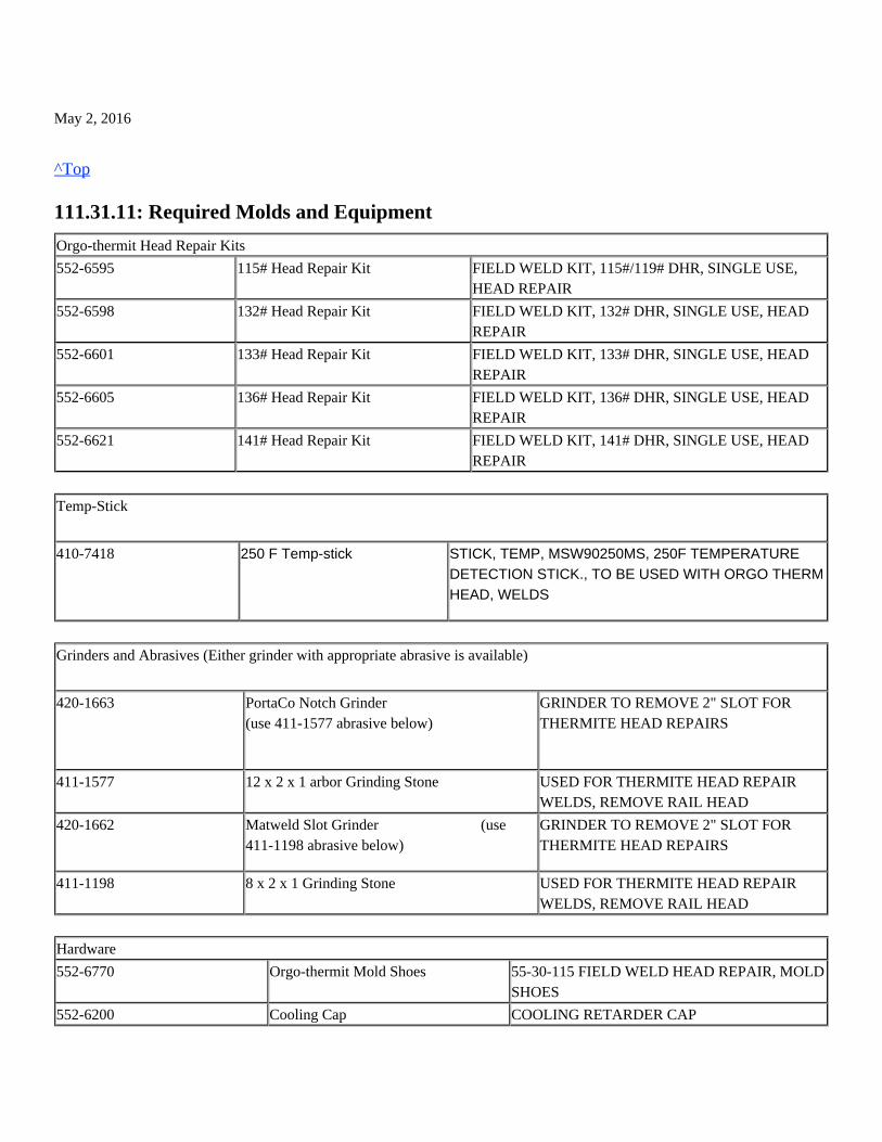
May 2, 2016
^Top
111.31.11: Required Molds and Equipment
Orgo-thermit Head Repair Kits
552-6595 115# Head Repair Kit FIELD WELD KIT, 115#/119# DHR, SINGLE USE,HEAD REPAIR
552-6598 132# Head Repair Kit FIELD WELD KIT, 132# DHR, SINGLE USE, HEADREPAIR
552-6601 133# Head Repair Kit FIELD WELD KIT, 133# DHR, SINGLE USE, HEADREPAIR
552-6605 136# Head Repair Kit FIELD WELD KIT, 136# DHR, SINGLE USE, HEADREPAIR
552-6621 141# Head Repair Kit FIELD WELD KIT, 141# DHR, SINGLE USE, HEADREPAIR
Temp-Stick
410-7418 250 F Temp-stick STICK, TEMP, MSW90250MS, 250F TEMPERATUREDETECTION STICK., TO BE USED WITH ORGO THERMHEAD, WELDS
Grinders and Abrasives (Either grinder with appropriate abrasive is available)
420-1663 PortaCo Notch Grinder(use 411-1577 abrasive below)
GRINDER TO REMOVE 2" SLOT FORTHERMITE HEAD REPAIRS
411-1577 12 x 2 x 1 arbor Grinding Stone USED FOR THERMITE HEAD REPAIRWELDS, REMOVE RAIL HEAD
420-1662 Matweld Slot Grinder (use411-1198 abrasive below)
GRINDER TO REMOVE 2" SLOT FORTHERMITE HEAD REPAIRS
411-1198 8 x 2 x 1 Grinding Stone USED FOR THERMITE HEAD REPAIRWELDS, REMOVE RAIL HEAD
Hardware
552-6770 Orgo-thermit Mold Shoes 55-30-115 FIELD WELD HEAD REPAIR, MOLDSHOES
552-6200 Cooling Cap COOLING RETARDER CAP
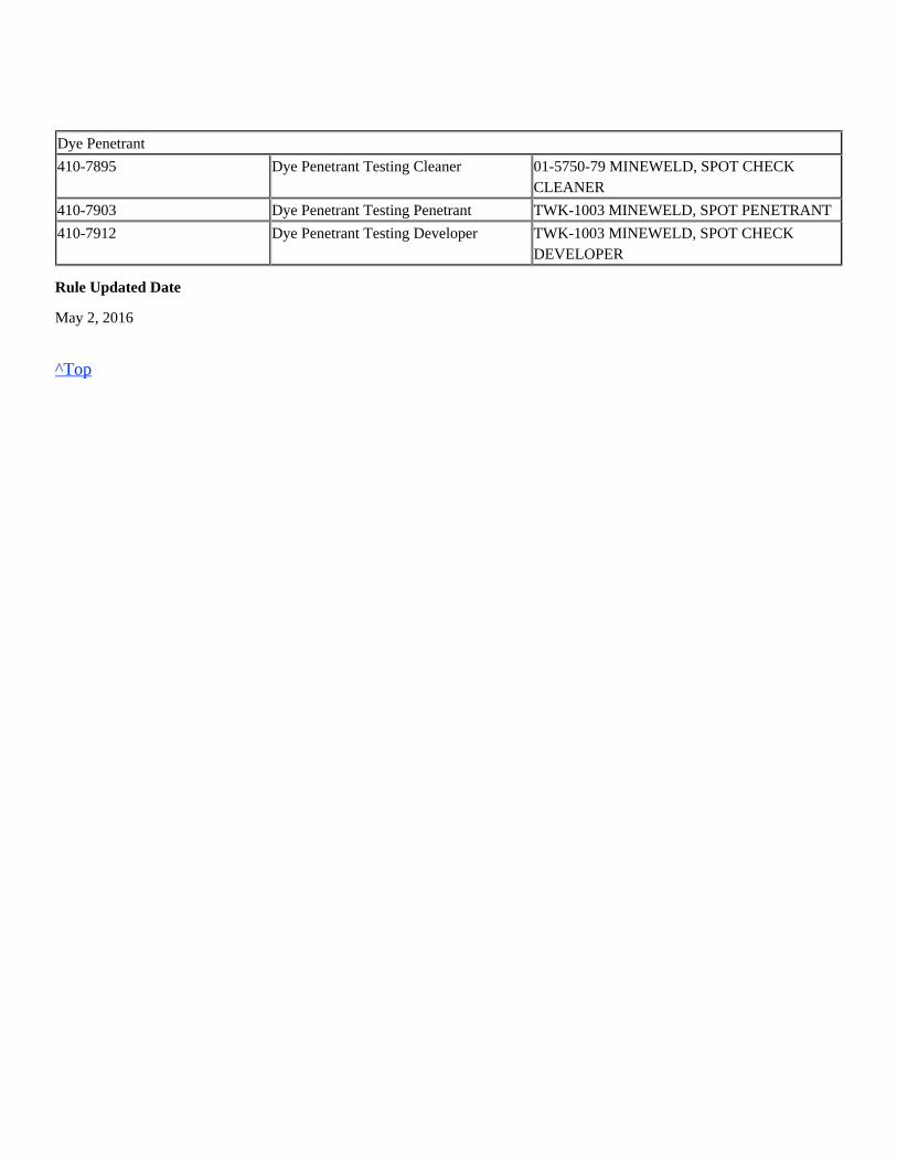
Dye Penetrant
410-7895 Dye Penetrant Testing Cleaner 01-5750-79 MINEWELD, SPOT CHECKCLEANER
410-7903 Dye Penetrant Testing Penetrant TWK-1003 MINEWELD, SPOT PENETRANT
410-7912 Dye Penetrant Testing Developer TWK-1003 MINEWELD, SPOT CHECKDEVELOPER
Rule Updated Date
May 2, 2016
^Top
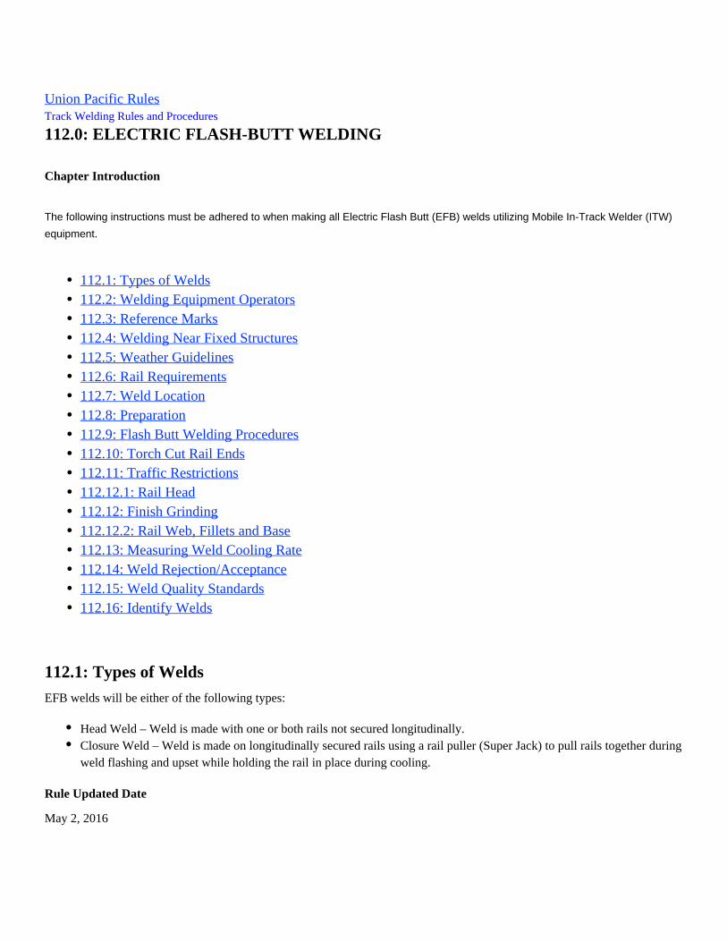
Union Pacific Rules Track Welding Rules and Procedures
112.0: ELECTRIC FLASH-BUTT WELDING
Chapter Introduction
The following instructions must be adhered to when making all Electric Flash Butt (EFB) welds utilizing Mobile In-Track Welder (ITW)
equipment.
112.1: Types of Welds
EFB welds will be either of the following types:
Rule Updated Date
May 2, 2016
112.1: Types of Welds112.2: Welding Equipment Operators112.3: Reference Marks112.4: Welding Near Fixed Structures112.5: Weather Guidelines112.6: Rail Requirements112.7: Weld Location112.8: Preparation112.9: Flash Butt Welding Procedures112.10: Torch Cut Rail Ends112.11: Traffic Restrictions112.12.1: Rail Head112.12: Finish Grinding112.12.2: Rail Web, Fillets and Base112.13: Measuring Weld Cooling Rate112.14: Weld Rejection/Acceptance112.15: Weld Quality Standards112.16: Identify Welds
Head Weld – Weld is made with one or both rails not secured longitudinally.Closure Weld – Weld is made on longitudinally secured rails using a rail puller (Super Jack) to pull rails together duringweld flashing and upset while holding the rail in place during cooling.
^Top
112.2: Welding Equipment Operators
Union Pacific employees operating the controls of electric flash butt welding equipment must do so under the direct supervision of a
qualified employee.
Rule Updated Date
May 2, 2016
^Top
112.3: Reference Marks
Reference marks must be placed on the rail prior to cutting rail and must be applied in accordance with the Engineering TrackMaintenance Field Handbook (ETMFH) - Section 7.9.2 Placing Reference Marks.The types of reference marks that are used to manage the CWR events are:
Rule Updated Date
May 2, 2016
^Top
112.4: Welding Near Fixed Structures
To minimize longitudinal stresses on track components, do not make closure welds within 150 feet of any rail crossing (diamond) or
. Apply solid box pattern rail anchors as per ETMFHturnout. All rail restraints must be applied between closure weld and frog
specification in turnouts. Closure welds must not change UPRR switch point to stock rail specifications.
Do not raise the rail neutral temperature above the subdivision rail laying temperature.
Care must be taken when working near detectors, insulated joints or other signal appliances.
When welding in or near a tunnel with a curve, do not over stretch the rail. Over stretching can disturb track alignment and decrease
tunnel clearances.
Rule Updated Date
May 2, 2016
Spanning reference marks are used for service failures, pull-aparts, detector car defects, track panels less than or equalto 80', rail change out less than or equal to 80'. Refer to Section 7.9.3 Placing Spanning Reference Marks.Pull back reference marks are used for rail change out greater than 80' or less than or equal to 360'and track panelsgreater than 80' or less than or equal to 360'. Refer to Section 7.9.4 Placing Pull Back Reference Marks.Match marks are used when rail change out is greater than 360'. Refer to Section 4.5.1.A Monitor Rail Movement.
^Top
112.5: Weather Guidelines
Union Pacific welding manager or welding supervisor will determine if conditions are safe for operation.Welding is prohibited if the first 30 inches of rail measured from each rail end cannot be kept dry.
1. Ensure that all welding machine fluids, including welding head and Super-Jack, are at operating temperature before startingwelding process.2. If raining or snowing, a welding blanket must be placed over the weld immediately after shearing to prevent moisture fromcontacting the weld; or during high wind conditions until the weld temperature is below 700° F.
Rule Updated Date
May 2, 2016
^Top
112.6: Rail Requirements
Replacement rail used for maintenance welding in an in-track operation must meet the following guidelines:
Rule Updated Date
May 2, 2016
^Top
112.7: Weld Location
When making welds in track, do not make a weld on top of a tie. If welds are made out-of-track and it is unknown where the weld will
lie once rail is installed, excess weld material must be ground from the bottom of, and both sides of the rail base flush with the parent
steel to properly fit in the tie plate or seat. Ensure there are two good ties immediately under each side of the weld for proper support.
Precautions must be taken to shield the weld from excessive moisture.Welding is permitted when the web of the rail can be heated, dried and kept dry until the weld is completed.
Minimum length of 15 feet.Vertical height difference from existing rail must not exceed 1/4 inch.Torch cut ends must re-cut with a rail saw.(See 112.10 below)Thermite welds must be removed when practical.Must be UT tested, certified and meet the installation requirements per Section 4 of the Engineering Track MaintenanceField Handbook.Do not EFB weld alloy rail.
(See Figure 112A)
Rule Updated Date
May 2, 2016
^Top
112.8: Preparation
Welding torch cut rail ends is prohibited.Before flash butt welding, do the following:
2. Remove by grinding, all raised lettering and other protrusions where the electrodes or jack wedges will contact the rail. 3. Clean rail ends of all foreign material. 4. All bolt holes should be eliminated when possible:
5. Prepare weld location:
1. Remove mill scale, rust, grease etc., where the welding electrodes will contact the rail web.
Area to be cleaned must be ground to bright metal.
Completed welds must not be closer than 6 inches from the center of any hole including bolt holes and rail bondholes.All bolt holes must be deburred, beveled and inspected for defects when left in the track.
Weld location must be between ties that will provide adequate clearance for shear as required includingremoving ballast.Track must be properly aligned and surfaced prior to welding.Adz wood ties if necessary to provide proper clearance for weld head.Anchors and fasteners must be removed to allow movement when aligning rail.All fasteners and plates removed must be kept clear of the welding head during the welding operation.On closure welds, remove a minimum of 300 feet of anchors or fasteners for standard consumption welds and aminimum of 200 feet for low consumption welds.If fixed track structures are encountered, remove additional anchors in the opposite directionWelds made out of track must have the bottom and sides of the rail base ground flush with parent metal.Do not weld battered rail ends or surface bent rails.
Rule Updated Date
May 2, 2016
^Top
112.9: Flash Butt Welding Procedures
Rail must be aligned vertically to provide finished welds that are within the vertical crown and vertical off-set dimensions atambient temperature. (Refer to Table112B)
Any rail end cut with a rail saw shall be cut square to within 1/8 inch both vertically and horizontally.
Rule Updated Date
May 2, 2016
^Top
112.10: Torch Cut Rail Ends
All rail ends prepared for electric flash butt welding shall be cut square with a rail saw. Welding torch cut rail ends isprohibited.Rail ends cut with an oxy-fuel torch will be trimmed back no less than 1/4 inch if done within 15 minutes of the initial torchcut.
If a completed weld must be re-welded and is torch cut due to rail in compression, trim back each rail end no less than 1/4inch. Trimming must be completed within 30 minutes of the torch cut.
Note: If rail is not in compression it may be possible to simply cut the rail with a rail saw.
If vertical rail height between rail ends is less than 1/8 inch, align the rail heads even and provide the off-set in the base.If vertical rail height between rail ends is 1/8 inch to 1/4 inch, spilt the difference between the base and rail head. (Donot offset the base more than 1/8 inch)If vertical rail height between rail ends is more than 1/4 inch, a better matching rail or compromise/transition rail mustbe installed.
Rail ends being welded that have a combined deviation of more than 1/4 inch will be rejected and must be re-cut.
If rail ends are not cut square top to bottom or side to side, the EFB equipment operator must not manually burn railsmore than 1/4 inch before starting the weld process. Any remaining excessive rail must be cut off with a rail saw.
As checked with the two rails touching.
If rail ends cannot be re-cut with a rail saw within 15 minutes of the torch cut, a minimum of 2 inches must be removedto get beyond the thermal heat cracks.
If the torch cut rail ends cannot be re-cut (trimmed) with a rail saw within 30 minutes, then a minimum of 2re-weldinches from each rail end must be removed to get beyond the thermal heat cracks.
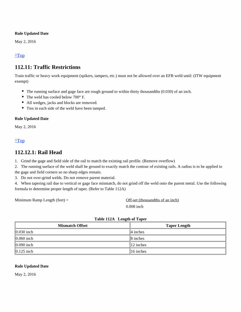
Rule Updated Date
May 2, 2016
^Top
112.11: Traffic Restrictions
Train traffic or heavy work equipment (spikers, tampers, etc.) must not be allowed over an EFB weld until: (ITW equipmentexempt)
Rule Updated Date
May 2, 2016
^Top
112.12.1: Rail Head
1. Grind the gage and field side of the rail to match the existing rail profile. (Remove overflow)2. The running surface of the weld shall be ground to exactly match the contour of existing rails. A radius is to be applied tothe gage and field corners so no sharp edges remain.3. Do not over-grind welds. Do not remove parent material.4. When tapering rail due to vertical or gage face mismatch, do not grind off the weld onto the parent metal. Use the followingformula to determine proper length of taper. (Refer to Table 112A) Minimum Ramp Length (feet) = Off-set (thousandths of an inch)
0.008 inch
Table 112A Length of Taper
Mismatch Offset Taper Length
0.030 inch 4 inches
0.060 inch 8 inches
0.090 inch 12 inches
0.125 inch 16 inches
Rule Updated Date
May 2, 2016
The running surface and gage face are rough ground to within thirty thousandths (0.030) of an inch.The weld has cooled below 700° F.All wedges, jacks and blocks are removed.Ties in each side of the weld have been tamped.
^Top
112.12: Finish Grinding
Rule Updated Date
May 2, 2016
^Top
112.12.2: Rail Web, Fillets and Base
When grinding rail web, fillets and base:1. Grind all welds smooth to within 1/16 inch of the original contour of the web and fillets. Do not grind into the parent metal.2. Grind the top of the base to within 1/16 inch of the original contour.3. Grind the sides of the base smooth.4. Visually inspect all welds for defects including where the current carrying electrodes make contact with the rail web.5. When shearing the upset, inspect the area on the web of every weld for gouges or smear. Reject any weld that has gougedinto the parent material. All smears must be ground from welds.
Rule Updated Date
May 2, 2016
^Top
112.13: Measuring Weld Cooling Rate
Weld temperature must be below 700° F before releasing welding head, super-jack or lowering crowning cylinders. Use apyrometer in the radius between the web and head of the weld.
Rule Updated Date
May 2, 2016
^Top
112.14: Weld Rejection/Acceptance
If welding system indicates the weld is out-of-spec or an interruption occurs during the cycle, weld must be consideredwelding
defective, removed and rail re-welded.
If an out-of-spec weld or bad weld is identified and marked by the welding system as shown on the weld certificate or chart, weld must
be removed and rail re-welded.
If no chart is available for weld, it must be removed and rail re-welded.
Weld charts and certificates must be reviewed by Union Pacific supervisory personnel and verified as a good weld before signing daily
weld production form, for each weld produced and left in track.
Rule Updated Date
May 2, 2016
^Top
112.15: Weld Quality Standards
Finished welds must meet the following requirements.
Table 112B Maximum Tolerance of Finished Ground Weld
VerticalCrown
VerticalOffset
HorizontalOffset
Horizontal Kink(1)
Base (HOS)Horizontal Offset
Base (VOS) VerticalOffset
Class 1-5 0.060" 0.020" 0.040" 0.025" 0.060" 0.125" *
Class 6 0.030" 0.020" 0.030" 0.025" 0.060" 0.125" *
(1) Measure on the convex side with straightedge centered on weld
* If rail height difference is greater than 0.125 inch, offset top of rail and grind. Any offset on the top of rail must be tapered to provide a
smooth transition. (See Figures 112B – 112H)
These are cold (ambient temperature), finish ground specifications. (Refer to Table 112B)
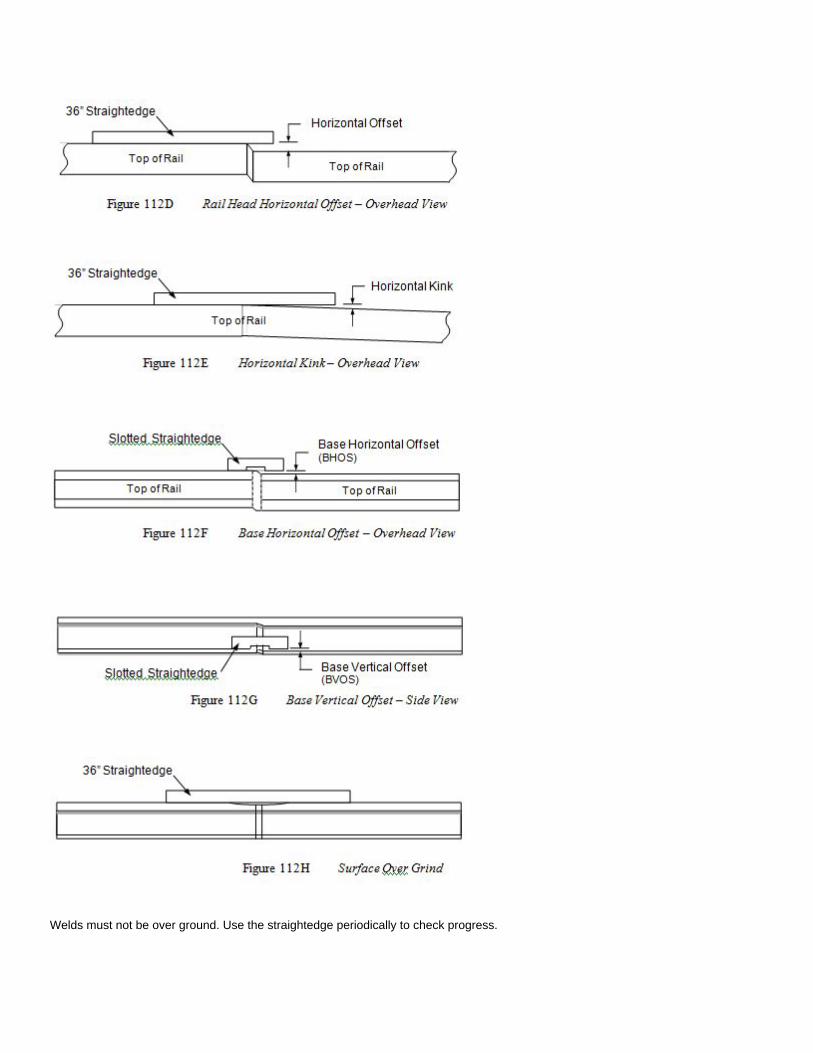
Welds must not be over ground. Use the straightedge periodically to check progress.
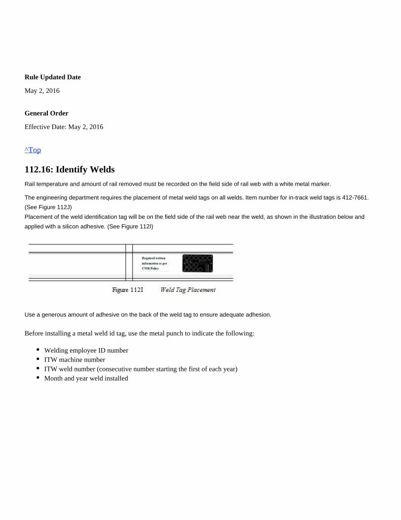
Rule Updated Date
May 2, 2016
General Order
Effective Date: May 2, 2016
^Top
112.16: Identify Welds
Rail temperature and amount of rail removed must be recorded on the field side of rail web with a white metal marker.
The engineering department requires the placement of metal weld tags on all welds. Item number for in-track weld tags is 412-7661.
(See Figure 112J)
Placement of the weld identification tag will be on the field side of the rail web near the weld, as shown in the illustration below and
applied with a silicon adhesive. (See Figure 112I)
Use a generous amount of adhesive on the back of the weld tag to ensure adequate adhesion.
Before installing a metal weld id tag, use the metal punch to indicate the following:
Welding employee ID numberITW machine numberITW weld number (consecutive number starting the first of each year)Month and year weld installed
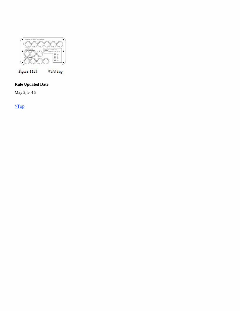
Rule Updated Date
May 2, 2016
^Top
Hard hat, hearing protection, type of eye protection as follows:
work gloves, welding jacket or welding sleeves, leather leggings, approved safety-toe boots and flameresistant clothing.
Union Pacific Rules Track Welding Rules and Procedures
113.0: SWITCH MAINTENANCE GRINDING
Chapter Introduction
These instructions apply to turnout maintenance grinding. The purpose of switch maintenance grinding is to increase the longevity of
the component by removing metal flow and restoring radius preventing chipping and cracking.
When performing any of these tasks, use frog and radius gauges to check and control the amount of grinding.
The RPM rating of abrasive wheel/stone must meet or exceed the RPM rating of the power equipment that is being used.
113.1: Personal Protective Equipment (PPE)
Task Required PPE
Abrasive
Grinding
See respiratory policy for respirator requirement.
Rule Updated Date
May 2, 2016
^Top
113.1: Personal Protective Equipment (PPE)113.2: Grinding Turnout and Crossing Frogs (Diamonds)113.2.1: Remove Flowed Metal113.2.2: Grind Slots113.2.3: Grind Running Rail113.3: Grinding Stock Rails and Switch Points113.3.1: Remove Flowed Metal113.3.2: Grind Switch Points113.4: Grinding and Slotting Rail Ends113.4.1: Use Proper Abrasive Wheels113.4.2: Slot Rail Ends
1.
2.
Welding hood with clear lens or in grind mode with safety glasses, or
Wrap-around face shield with goggles or safety glasses (#5 shade must be worn),not
113.2: Grinding Turnout and Crossing Frogs (Diamonds)
Rule Updated Date
May 2, 2016
^Top
113.2.1: Remove Flowed Metal
Rule Updated Date
May 2, 2016
^Top
113.2.2: Grind Slots
Abrasive wheels used in slotting must not be more than 1/8 inch thick. Appropriate blotters must be used between the abrasivewheel and metal flange.A. Carbon Rail FrogsOn carbon rail frogs, slot to a depth of at least 3/16-inch and slightly bevel the top:
B. Manganese Insert Frogs
On manganese insert frogs, slot to a depth of at least 3/16-inch and slightly bevel the top:
Rule Updated Date
May 2, 2016
^Top
113.2.3: Grind Running Rail
Remove metal flow from running rails in the area adjacent to guardrails.
1.
2.
3.
Remove all flowed metal from the gage side corner of the frog.
Apply steady pressure to effectively remove metal without gouging the parent steel.
Grind the gage side corner to a 5/8 inch radius.
Slot between the short point and the adjacent rail.Slot between the filler block at the heel of the frog and the adjacent rail.
Slot between the insert and the binder rails.Slot between the narrow portion of the manganese insert and the carbon steel heel leg extension rails at the heel of thefrog.
Rule Updated Date
March 1, 2007
^Top
113.3: Grinding Stock Rails and Switch Points
Rule Updated Date
March 1, 2007
^Top
113.3.1: Remove Flowed Metal
Remove all flowed metal from the gage and field sides of the stock rail as follows:
Rule Updated Date
May 2, 2016
^Top
113.3.2: Grind Switch Points
Grind switch points as follows:
1.
2.
3.
4.
5.
On gage side, remove metal flow 4 inches ahead of the switch point and grind back to where the switch point ends contactwith the stock rail.
Ensure no sharp projections remain after grinding.
Ensure the flowed metal on stock rail is tapered back from the switch point at a minimum of 4 inches to eliminate a sharpcorner.
Grind the gage and field sides of the stock rail to a 5/16-inch to 9/16-inch radius.
When grinding Samson stock rails, it is important not to change the dimension of the gage face. Only apply enoughpressure to remove metal flow without gouging the parent steel or changing the angle of the gage face.
1.
2.
3.
4.
Ensure tip of the point is 5/8 inch to 3/4 inch lower than the stock rail. Refer to standard drawings for specific dimensionsof various size switch points.
Remove metal flow on the back of switch point to obtain a close fit between switch point and stock rail.
The back of the switch point must be slightly beveled at the top, except the first 10 inches from the end of the point.
Slot the rail ends at the heel of the switch point.
a.
b.
Ensure the top of the point tapers back so the first 8 inches of the point will not carry any load.
Remove metal flow on the gage side of the switch point and restore to a 5/16-inch to 9/16-inch radius.
Rule Updated Date
March 1, 2007
^Top
113.4: Grinding and Slotting Rail Ends
Rule Updated Date
March 1, 2007
^Top
113.4.1: Use Proper Abrasive Wheels
Abrasive wheels used in slotting rail ends must not be more than 1/8 inch thick. Rubber or paper blotters must be used betweenthe abrasive wheel and metal flange.
Rule Updated Date
March 1, 2007
^Top
113.4.2: Slot Rail Ends
After surface grinding, slot rail ends to the required dimensions using proper equipment.
The following procedures apply to slotting rail ends:
Open Joints:
Closed Joint:
Insulated Joints:
The slot should match the contour of the rail end.Avoid cutting into or nicking the joint bars.
Square the rail end by removing any metal flow by grinding.Slot the rail end to 1/4 inch to 5/16 inch deep.Bevel the rail end to 1/16 inch to 3/32 inch back.
Center the slotting wheel between the rail ends of closed joints to remove an equal amount of metal from each rail.Slot the rail end to 1/4 inch to 5/16 inch deep. Slot to a width of 3/16 inch.
Slot Outside Rail of Curves:
On the outside rail of curves, continue slotting over and around the gauge side to include the area usually engaged by the wheelflange.
Rule Updated Date
March 1, 2007
^Top
Remove only flowed metal from rail ends and ensure no sharp edges remain.Avoid cutting the end post as much as possible.Do not slot any deeper than necessary to remove flowed metal.
Avoid nicking or grinding the joint bar.
Union Pacific Rules Track Welding Rules and Procedures
114.0: DEFINITIONS
114.0: Definitions
ACETONE:A flammable, volatile liquid used in acetylene cylinders to dissolve and stabilize acetylene under high pressure.
ACETYLENE:A highly combustible gas composed of carbon and hydrogen. Used as a fuel gas in the oxyacetylene welding process.
AIR-ARC CUTTING:An arc cutting process in which metals to be cut are melted by the heat of the carbon arc.
ALLOY:A mixture with metallic properties composed of two or more elements, of which at least one is a metal.
ALTERNATING CURRENT:An electric current that reverses its direction at regularly recurring intervals.
ANNEALING:A comprehensive term used to describe the heating and cooling cycle of steel in the solid state. The term annealing usuallyimplies relatively slow cooling. In annealing, the temperature of the operation, the rate of heating and cooling, and the time themetal is held at heat depend upon the composition, shape, and size of the steel product being treated, and the purpose of thetreatment. The more important purposes for which steel is annealed are as follows: to remove stresses; to induce softness; toalter ductility, toughness, electric, magnetic, or other physical and mechanical properties; to change the crystalline structure; toremove gases; and to produce a definite microstructure.
ARC BLOW:The deflection of an electric arc from its normal path because of magnetic forces.
ARC CUTTING:A group of cutting processes in which the cutting of metals is accomplished by melting with the heat of an arc between theelectrode and the base metal. See CARBON-ARC CUTTING, METAL-ARC CUTTING, ARC-OXYGEN CUTTING, ANDAIR-ARC CUTTING.
ARC LENGTH:The distance between the tip of the electrode and the weld puddle.
ARC VOLTAGE:The voltage across the welding arc.
114.0: Definitions
ARC WELDING:A group of welding processes in which fusion is obtained by heating with an electric arc or arcs, with or without the use offiller metal.
AS WELDED:The condition of weld metal, welded joints, and weldments after welding and prior to any subsequent thermal, mechanical, orchemical treatments.
BACK FIRE:The momentary burning back of a flame into the tip, followed by a snap or pop, then immediate reappearance or burning out ofthe flame.
BASE METAL:The metal to be welded or cut. In alloys, it is the metal present in the largest proportion.
CARBON-ARC CUTTING:A process of cutting metals with the heat of an arc between a carbon electrode and the work.
CARBONIZING FLAME:An oxyacetylene flame in which there is an excess of acetylene. Also called excess acetylene or reducing flame.
CRACK:A fracture type discontinuity characterized by a sharp tip and high ratio of length and width to opening displacement.
CRATER:A depression at the termination of an arc weld.
CUTTING TIP:A gas torch tip especially adapted for cutting.
CUTTING TORCH:A device used in gas cutting for controlling the gases used for preheating and the oxygen used for cutting the metal.
CYLINDER:A portable cylindrical container used for the storage of a compressed gas.
DEFECT:A discontinuity or discontinuities which, by nature or accumulated effect (for example, total crack length), render a part orproduct unable to meet the minimum applicable acceptance standards or specifications. This term designates rejectability.
DEPOSITED METAL:Filler metal that has been added during a welding operation.
DEPOSITION EFFICIENCY:The ratio of the weight of deposited metal to the net weight of electrodes consumed, exclusive of stubs.
DEPTH OF FUSION:The distance from the original surface of the base metal to that point at which fusion ceases in a welding operation.
DIRECT CURRENT ELECTRODE NEGATIVE (DCEN):The arrangement of direct current arc welding leads in which the work is the positive pole and the electrode is the negativepole of the welding arc.
DIRECT CURRENT ELECTRODE POSITIVE (DCEP):The arrangement of direct current arc welding leads in which the work is the negative pole and the electrode is the positivepole of the welding arc.
DISCONTINUITY:An interruption of the typical structure of a weldment, such as lack of homogeneity in the mechanical, metallurgical, orphysical characteristics of the material or weldment. A discontinuity is not necessarily a defect.
DUCTILITY:The property of a metal which allows it to be permanently deformed, in tension, before final rupture. Ductility is commonlyevaluated by tensile testing in which the amount of elongation and the reduction of area of the broken specimen, as comparedto the original test specimen, are measured and calculated.
DUTY CYCLE:The percentage of time during an arbitrary test period, usually 10 minutes, during which a power supply can be operated at itsrated output without overloading.
EFFECTIVE LENGTH OF WELD:
The length of weld throughout which the correctly proportioned cross section exits.
ELECTRODE:
ELECTRODE HOLDER:A device used for mechanically holding the electrode and conducting current to it.
FACE OF WELD:The exposed surface of a weld, made by an arc or gas welding process, on the side from which welding was done.
FILLER METAL:Metal to be added in making a weld.
FILTER GLASS:A colored glass used in goggles, helmets, and shields to exclude harmful light rays.
FLAME HARDENING:A method for hardening a steel surface by heating with a gas flame followed by a rapid quench.
FLAME SOFTENING:A method for softening steel by heating with a gas flame followed by slow cooling.
FLASHBACK:The burning of gases within the torch or beyond the torch in the hose, usually with a shrill, hissing sound.
FLAT POSITION:The position in which welding is performed from the upper side of the joint and the face of the weld is approximatelyhorizontal.
a.
b.
Metal-Arc. Filler metal in the form of a wire or rod, whether bare or covered, through which current is conducted betweenthe electrode holder and the arc.
Carbon-Arc. A carbon or graphite rod through which current is conducted between the electrode holder and the arc.
FLUX:A cleaning agent used to dissolve oxides, release trapped gases and slag, and to cleanse metals for welding, soldering, andbrazing.
FUSION:A thorough and complete mixing between the two edges of the base metal to be joined or between the base metal and the fillermetal added during welding.
FUSION ZONE (FILLER PENETRATION):The area of base metal melted as determined on the cross section of a weld.
GAS POCKET:A weld cavity caused by the trapping of gases released by the metal when cooling.
GAS WELDING:A process in which the welding heat is obtained from a gas flame.
GOGGLES:A device with colored lenses, which protect the eyes from harmful radiation during welding and cutting operations.
GROUND CONNECTION:The connection of the work lead to the work.
HARD FACING:A particular form of surfacing in which a coating or cladding is applied to a surface for the main purpose of reducing wear orloss of material by abrasion, impact, erosion, galling, and cavitations.
HARD SURFACING:The application of a hard, wear-resistant alloy to the surface of a softer metal.
HARDENING:
HEAT AFFECTED ZONE:That portion of the base metal whose structure or properties have been changed by the heat of welding or cutting.
HEAT TIME:The duration of each current impulse in pulse welding.
HEAT TREATMENT:An operation or combination of operations involving the heating and cooling of a metal or an alloy in the solid state for thepurpose of obtaining certain desirable conditions or properties. Heating and cooling for the sole purpose of mechanical workingare excluded from the meaning of the definition.
HELMET:A device used in arc welding to protect the face and neck. It is equipped with a filter glass and is designed to be worn on thehead.
a.
b.
The heating and quenching of certain iron-base alloys from a temperature above the critical temperature range for thepurpose of producing a hardness superior to that obtained when the alloy is not quenched. This term is usually restricted tothe formation of Martensite.
Any process of increasing the hardness of metal by suitable treatment, usually involving heating and cooling.
HOT SHORT:A condition which occurs when a metal is heated to that point, prior to melting, where all strength is lost but the shape is stillmaintained.
INERT GAS:A gas which does not normally combine chemically with the base metal or filler metal.
INTERPASS TEMPERATURE:In a multi-pass weld, the lowest temperature of the deposited weld meal before the next pass is started.
KERF:The space from which metal has been removed by a cutting process.
LAYER:A stratum of weld metal, consisting of one or more weld beads.
MANIFOLD:A multiple header for connecting several cylinders to one or more torch supply lines.
MARTENSITE:Martensite is a microconstituent or structure in quenched steel characterized by an acicular or needle-like pattern on the surfaceof polish. It has the maximum hardness of any of the structures resulting from the decomposition products of austenite.
MELTING POINT:The temperature at which a metal begins to liquefy.
MELTING RANGE:The temperature range between solid and liquid.
METAL-ARC WELDING:An arc welding process in which a metal electrode is held so that the heat of the arc fuses both the electrode and the work toform a weld.
MIXING CHAMBER:That part of a welding or cutting torch in which the gases are mixed for combustion.
NEUTRAL FLAME:A gas flame in which the oxygen and acetylene volumes are balanced and both gases are completely burned.
NONFERROUS:Metals which contain no iron. Aluminum, brass, bronze, copper, lead, nickel, and titanium are nonferrous.
NORMALIZING:Heating iron-base alloys to approximately 100 °F (38 °C) above the critical temperature range followed by cooling to belowthat range in still air at ordinary temperature.
OPEN CIRCUIT VOLTAGE:The voltage between the terminals of the welding source when no current is flowing in the welding circuit.
OVERLAP:The protrusion of weld metal beyond the bond at the toe of the weld.
OXIDIZING FLAME:An oxyacetylene flame in which there is an excess of oxygen. The unburned excess tends to oxidize the weld metal.
OXYACETYLENE CUTTING:An oxygen cutting process in which the necessary cutting temperature is maintained by flames obtained from the combustionof acetylene with oxygen.
OXYACETYLENE WELDING:A welding process in which the required temperature is attained by flames obtained from the combustion of acetylene withoxygen.
OXY-PROPANE CUTTING:An oxygen cutting process in which the necessary cutting temperature is maintained by flames obtained from the combustionof propane with oxygen.
PASS:The weld metal deposited in one general progression along the axis of the weld.
PEENING:The mechanical working of metals by means of hammer blows. Peening tends to stretch the surface of the cold metal, therebyrelieving contraction stresses.
POROSITY:The presence of gas pockets or inclusions in welding.
POSITIONS OF WELDING:All welding is accomplished in one of four positions: flat, horizontal, overhead, and vertical. The limiting angles of the variouspositions depend somewhat as to whether the weld is a fillet or groove weld.
POSTHEATING:The application of heat to an assembly after a welding, brazing, soldering, thermal spraying, or cutting operation.
PREHEATING:The application of heat to a base metal prior to a welding or cutting operation.
QUENCHING:The sudden cooling of heated metal with oil, water, or compressed air.
REGULATOR:A device used to reduce cylinder pressure to a suitable torch working pressure.
REVERSE POLARITY:The arrangement of direct current arc welding leads in which the work is the negative pole and the electrode is the positivepole of the welding arc.
ROCKWELL HARDNESS TEST:In this test a machine measures hardness by determining the depth of penetration into the specimen under certain arbitraryfixed conditions of test. The penetrator may be either a steel ball or a diamond spherocone.
ROOT CRACK:A crack in the weld or base metal which occurs at the root of a weld.
ROOT FACE:The portion of the prepared edge of a member to be joined by a groove weld which is not beveled or grooved.
SHIELDED WELDING:An arc welding process in which protection from the atmosphere is obtained through use of a flux, decomposition of theelectrode covering, or an inert gas.
SLAG INCLUSION:Non-metallic solid material entrapped in the weld metal or between the weld metal and the base metal.
SPALL:Small chips or fragments which are sometimes given off by electrodes during the welding operation. This problem is especiallycommon with heavy-coated electrodes.
SPATTER:The metal particles expelled during arc and gas welding which do not form a part of the weld.
STRAIGHT POLARITY:The arrangement of direct current arc welding leads in which the work is the positive pole and the electrode is the negativepole of the welding arc.
STRESS RELIEVING:A process of reducing internal residual stresses in a metal object by heating to a suitable temperature and holding for a propertime at that temperature. This treatment may he applied to relieve stresses induced by casting, quenching, normalizing,machining, cold working, or welding.
STRING BEAD WELDING:A method of metal arc welding on pieces 3/4 in. (19 mm) thick or heavier in which the weld metal is deposited in layerscomposed of strings of beads applied directly to the face of the bevel.
TEMPORARY RAIL END BUILDUP:Welding beads applied on the lower rail to protect the taller rail when rail ends are mismatched. Rail ends must be properlyprepared and preheated before welding, then postheated when completed.
THERMAL CONDUCTIVITY:The rate at which temperature travels through metal.
THERMITE CRUCIBLEThe vessel in which the thermit reaction takes place.
THERMITE MIXTURE:A mixture of metal oxide and finely divided aluminum with the addition of alloying metals as required.
THERMITE MOLD:A mold formed around the parts to be welded to receive the molten metal.
THERMITE REACTION:The chemical reaction between metal oxide and aluminum, which produces, superheated molten metal and aluminum oxideslag.
THERMITE WELDING:A group of welding processes in which fusion is produced by heating with superheated liquid metal and slag resulting from a
chemical reaction between a metal oxide and aluminum, with or without the application of pressure. Filler metal, when used, isobtained from the liquid metal.
UNDERCUT:A groove melted into the base metal adjacent to the toe or root of a weld and left unfilled by weld metal.
UNDERCUTTING:An undesirable crater at the edge of the weld caused by poor weaving technique or excessive welding speed.
UPSET:A localized increase in volume in the region of a weld, resulting from the application of pressure.
UPSET WELDING:A resistance welding process in which fusion is produced simultaneously over the entire area of abutting surfaces, orprogressively along a joint, by the heat obtained from resistance to the flow of electric current through the area of contact ofthose surfaces. Pressure is applied before heating is started and is maintained throughout the heating period.
UPSETTING FORCE:The force exerted at the welding surfaces in flash or upset welding.
WEAVE BEAD:A type of weld bead made with transverse oscillation.
WEAVING:A technique of depositing weld metal in which the electrode is oscillated. It is usually accomplished by a semicircular motionof the arc to the right and left of the direction of welding. Weaving serves to increase the width of the deposit, decreasesoverlap, and assists in slag formation.
WELD:A localized fusion of metals produced by heating to suitable temperatures. Pressure and/or filler metal may or may not beused. The filler material has a melting point approximately the same or below that of the base metals, but always above 800 °F(427 °C).
WELD BEAD:A weld deposit resulting from a pass.
WELD GAUGE:A device designed for checking the shape and size of welds.
WELD METAL:That portion of a weld that has been melted during welding.
WELD SYMBOL:A picture used to indicate the desired type of weld.
WELDABILITY:The capacity of a material to form a strong bond of adherence under pressure or when solidifying from a liquid.
WELDER CERTIFICATION:Certification in writing that a welder has produced welds meeting prescribed standards.
WELDER PERFORMANCE QUALIFICATION:The demonstration of a welder's ability to produce welds meeting prescribed standards.
WELDING LEADS:
WELDING PRESSURE:The pressure exerted during the welding operation on the parts being welded.
WELDING ROD:Filler metal in wire or rod form, used in gas welding and brazing processes and in those arc welding processes in which theelectrode does not provide the filler metal.
WELDING TECHNIQUE:The details of a manual, machine, or semiautomatic welding operation which, within the limitations of the prescribed jointwelding procedure, are controlled by the welder or welding operator.
WELDING TIP:The tip of a gas torch especially adapted to welding.
WELDING TORCH:A device used in gas welding and torch brazing for mixing and controlling the flow of gases.
WELDING TRANSFORMER:A device for providing current of the desired voltage.
WELDMENT:An assembly whose component parts are formed by welding.
WORK LEAD:The electric conductor (cable) between the source of arc welding current and the workpiece.
Rule Updated Date
May 2, 2016
^Top
a.
b.
Electrode lead. The electrical conductor between the source of the arc current and the electrode holder.
Work lead. The electrical conductor between the source of the arc welding current and the workpiece.
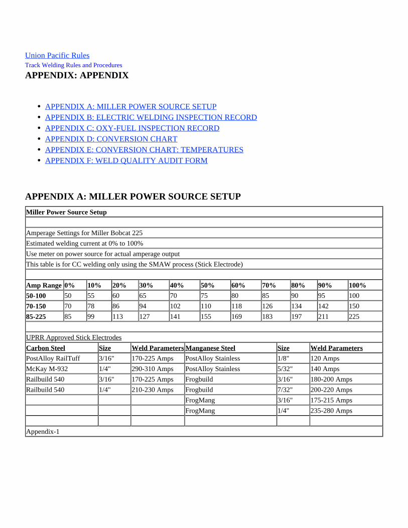
Union Pacific Rules Track Welding Rules and Procedures
APPENDIX: APPENDIX
APPENDIX A: MILLER POWER SOURCE SETUP
Miller Power Source Setup
Amperage Settings for Miller Bobcat 225
Estimated welding current at 0% to 100%
Use meter on power source for actual amperage output
This table is for CC welding only using the SMAW process (Stick Electrode)
Amp Range 0% 10% 20% 30% 40% 50% 60% 70% 80% 90% 100%
50-100 50 55 60 65 70 75 80 85 90 95 100
70-150 70 78 86 94 102 110 118 126 134 142 150
85-225 85 99 113 127 141 155 169 183 197 211 225
UPRR Approved Stick Electrodes
Carbon Steel Size Weld Parameters Manganese Steel Size Weld Parameters
PostAlloy RailTuff 3/16" 170-225 Amps PostAlloy Stainless 1/8" 120 Amps
McKay M-932 1/4" 290-310 Amps PostAlloy Stainless 5/32" 140 Amps
Railbuild 540 3/16" 170-225 Amps Frogbuild 3/16" 180-200 Amps
Railbuild 540 1/4" 210-230 Amps Frogbuild 7/32" 200-220 Amps
FrogMang 3/16" 175-215 Amps
FrogMang 1/4" 235-280 Amps
Appendix-1
APPENDIX A: MILLER POWER SOURCE SETUPAPPENDIX B: ELECTRIC WELDING INSPECTION RECORDAPPENDIX C: OXY-FUEL INSPECTION RECORDAPPENDIX D: CONVERSION CHARTAPPENDIX E: CONVERSION CHART: TEMPERATURESAPPENDIX F: WELD QUALITY AUDIT FORM
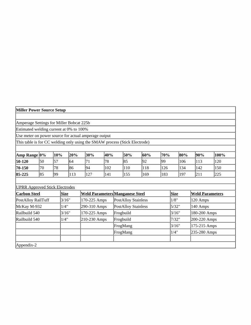
Miller Power Source Setup
Amperage Settings for Miller Bobcat 225b
Estimated welding current at 0% to 100%
Use meter on power source for actual amperage output
This table is for CC welding only using the SMAW process (Stick Electrode)
Amp Range 0% 10% 20% 30% 40% 50% 60% 70% 80% 90% 100%
50-120 50 57 64 71 78 85 92 99 106 113 120
70-150 70 78 86 94 102 110 118 126 134 142 150
85-225 85 99 113 127 141 155 169 183 197 211 225
UPRR Approved Stick Electrodes
Carbon Steel Size Weld Parameters Manganese Steel Size Weld Parameters
PostAlloy RailTuff 3/16" 170-225 Amps PostAlloy Stainless 1/8" 120 Amps
McKay M-932 1/4" 290-310 Amps PostAlloy Stainless 5/32" 140 Amps
Railbuild 540 3/16" 170-225 Amps Frogbuild 3/16" 180-200 Amps
Railbuild 540 1/4" 210-230 Amps Frogbuild 7/32" 200-220 Amps
FrogMang 3/16" 175-215 Amps
FrogMang 1/4" 235-280 Amps
Appendix-2
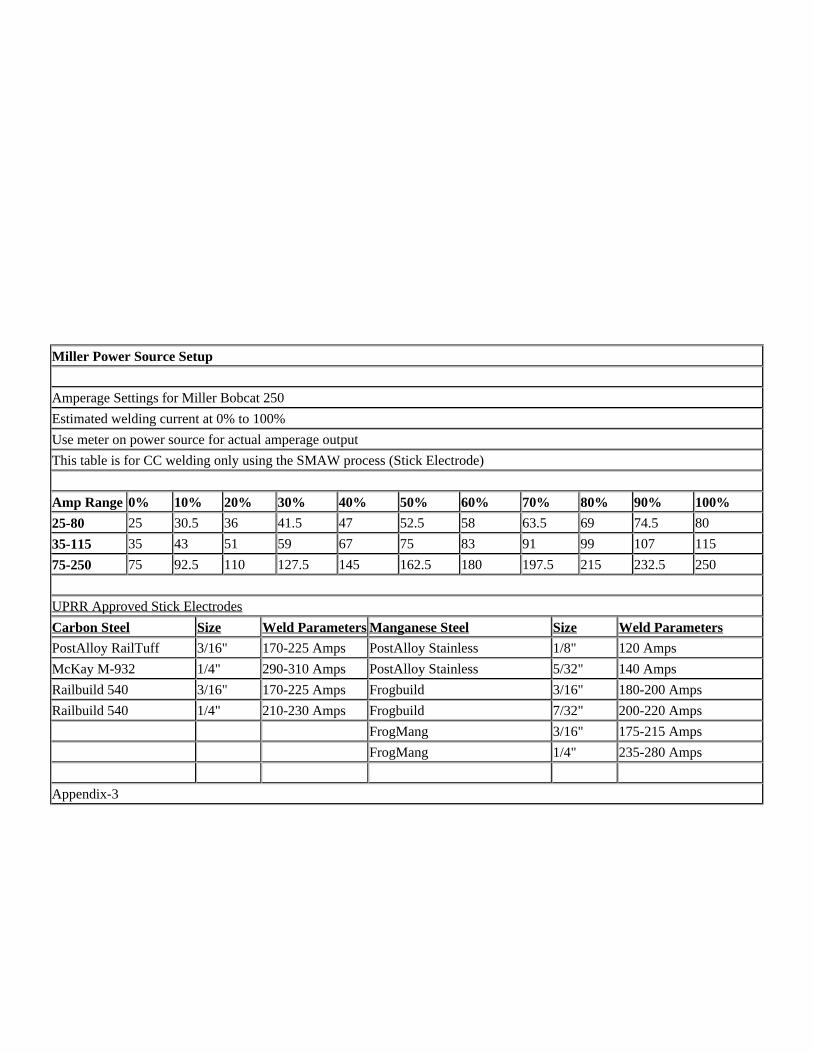
Miller Power Source Setup
Amperage Settings for Miller Bobcat 250
Estimated welding current at 0% to 100%
Use meter on power source for actual amperage output
This table is for CC welding only using the SMAW process (Stick Electrode)
Amp Range 0% 10% 20% 30% 40% 50% 60% 70% 80% 90% 100%
25-80 25 30.5 36 41.5 47 52.5 58 63.5 69 74.5 80
35-115 35 43 51 59 67 75 83 91 99 107 115
75-250 75 92.5 110 127.5 145 162.5 180 197.5 215 232.5 250
UPRR Approved Stick Electrodes
Carbon Steel Size Weld Parameters Manganese Steel Size Weld Parameters
PostAlloy RailTuff 3/16" 170-225 Amps PostAlloy Stainless 1/8" 120 Amps
McKay M-932 1/4" 290-310 Amps PostAlloy Stainless 5/32" 140 Amps
Railbuild 540 3/16" 170-225 Amps Frogbuild 3/16" 180-200 Amps
Railbuild 540 1/4" 210-230 Amps Frogbuild 7/32" 200-220 Amps
FrogMang 3/16" 175-215 Amps
FrogMang 1/4" 235-280 Amps
Appendix-3
Miller Power Source Setup
Amperage Settings for Miller Trailblazer 250G
Estimated welding current at 0% to 100%
Use meter on power source for actual amperage output
This table is for CC welding only using the SMAW process (Stick Electrode)
Amp Range 0% 10% 20% 30% 40% 50% 60% 70% 80% 90% 100%
25-80 25 30.5 36 41.5 47 52.5 58 63.5 69 74.5 80
35-115 35 43 51 59 67 75 83 91 99 107 115
75-250 75 92.5 110 127.5 145 162.5 180 197.5 215 232.5 250
UPRR Approved Stick Electrodes
Carbon Steel Size Weld Parameters Manganese Steel Size Weld Parameters
PostAlloy RailTuff 3/16" 170-225 Amps PostAlloy Stainless 1/8" 120 Amps
McKay M-932 1/4" 290-310 Amps PostAlloy Stainless 5/32" 140 Amps
Railbuild 540 3/16" 170-225 Amps Frogbuild 3/16" 180-200 Amps
Railbuild 540 1/4" 210-230 Amps Frogbuild 7/32" 200-220 Amps
FrogMang 3/16" 175-215 Amps
FrogMang 1/4" 235-280 Amps
Appendix-4
Miller Power Source Setup
Amperage Settings for Miller AirPac 400
Estimated welding current at 0% to 100%
Use meter on power source for actual amperage output
This table is for CC welding only using the SMAW process (Stick Electrode)
Amp Range 0% 10% 20% 30% 40% 50% 60% 70% 80% 90% 100%
85-210 85 97.5 110 122.5 135 147.5 160 172.5 185 197.5 210
110-270 110 126 142 158 174 190 206 222 238 254 270
190-400 190 211 232 253 274 295 316 337 358 379 400
UPRR Approved Stick Electrodes
Carbon Steel Size Weld Parameters Manganese Steel Size Weld Parameters
PostAlloy RailTuff 3/16" 170-225 Amps PostAlloy Stainless 1/8" 120 Amps
McKay M-932 1/4" 290-310 Amps PostAlloy Stainless 5/32" 140 Amps
Railbuild 540 3/16" 170-225 Amps Frogbuild 3/16" 180-200 Amps
Railbuild 540 1/4" 210-230 Amps Frogbuild 7/32" 200-220 Amps
FrogMang 3/16" 175-215 Amps
FrogMang 1/4" 235-280 Amps
Appendix-5
Miller Power Source Setup
Amperage Settings for Miller AirPac 500
Estimated welding current at 0% to 100%
Use meter on power source for actual amperage output
This table is for CC welding only using the SMAW process (Stick Electrode)
Amp Range 0% 10% 20% 30% 40% 50% 60% 70% 80% 90% 100%
90-190 90 100 110 120 130 140 150 160 170 180 190
140-330 140 159 178 197 216 235 254 273 292 311 330
200-500 200 230 260 290 320 350 380 410 440 470 500
UPRR Approved Stick Electrodes
Carbon Steel Size Weld Parameters Manganese Steel Size Weld Parameters
PostAlloy RailTuff 3/16" 170-225 Amps PostAlloy Stainless 1/8" 120 Amps
McKay M-932 1/4" 290-310 Amps PostAlloy Stainless 5/32" 140 Amps
Railbuild 540 3/16" 170-225 Amps Frogbuild 3/16" 180-200 Amps
Railbuild 540 1/4" 210-230 Amps Frogbuild 7/32" 200-220 Amps
FrogMang 3/16" 175-215 Amps
FrogMang 1/4" 235-280 Amps
Appendix-6
Miller Power Source Setup
Amperage Settings for Miller AirPac 750 Generating Power CC/CV – DC Only(525 Amp 100% Duty Cycle / 550 Amp 60% Duty Cycle / 600 Amp 40% Duty Cycle)
Estimated welding current at 0% to 100%
Use meter on power source for actual amperage output
This table is for CC welding only using the SMAW process (Stick Electrode)
Amp Range 0% 10% 20% 30% 40% 50% 60% 70% 80% 90% 100%
85-250 85 101.5 118 134.5 151 167.5 184 200.5 217 233.5 250
125-400 125 152.5 180 207.5 235 262.5 290 317.5 345 372.5 400
185-525 185 219 253 287 321 355 389 423 457 491 525
UPRR Approved Stick Electrodes
Carbon Steel Size Weld Parameters Manganese Steel Size Weld Parameters
PostAlloy RailTuff 3/16" 170-225 Amps PostAlloy Stainless 1/8" 120 Amps
McKay M-932 1/4" 290-310 Amps PostAlloy Stainless 5/32" 140 Amps
Railbuild 540 3/16" 170-225 Amps Frogbuild 3/16" 180-200 Amps
Railbuild 540 1/4" 210-230 Amps Frogbuild 7/32" 200-220 Amps
FrogMang 3/16" 175-215 Amps
FrogMang 1/4" 235-280 Amps
Appendix-7
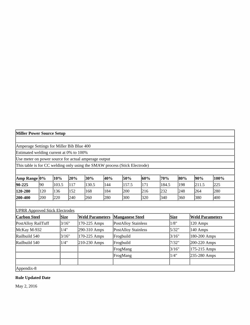
Miller Power Source Setup
Amperage Settings for Miller Bib Blue 400
Estimated welding current at 0% to 100%
Use meter on power source for actual amperage output
This table is for CC welding only using the SMAW process (Stick Electrode)
Amp Range 0% 10% 20% 30% 40% 50% 60% 70% 80% 90% 100%
90-225 90 103.5 117 130.5 144 157.5 171 184.5 198 211.5 225
120-280 120 136 152 168 184 200 216 232 248 264 280
200-400 200 220 240 260 280 300 320 340 360 380 400
UPRR Approved Stick Electrodes
Carbon Steel Size Weld Parameters Manganese Steel Size Weld Parameters
PostAlloy RailTuff 3/16" 170-225 Amps PostAlloy Stainless 1/8" 120 Amps
McKay M-932 1/4" 290-310 Amps PostAlloy Stainless 5/32" 140 Amps
Railbuild 540 3/16" 170-225 Amps Frogbuild 3/16" 180-200 Amps
Railbuild 540 1/4" 210-230 Amps Frogbuild 7/32" 200-220 Amps
FrogMang 3/16" 175-215 Amps
FrogMang 1/4" 235-280 Amps
Appendix-8
Rule Updated Date
May 2, 2016
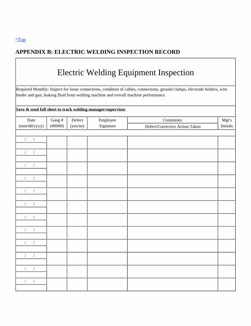
^Top
APPENDIX B: ELECTRIC WELDING INSPECTION RECORD
Electric Welding Equipment Inspection
Required Monthly: Inspect for loose connections, condition of cables, connections, ground clamps, electrode holders, wirefeeder and gun, leaking fluid from welding machine and overall machine performance.
Save & send full sheet to track welding manager/supervisor
Date(mm/dd/yyyy)
Gang #(#0000)
Defect(yes/no)
EmployeeSignature
Comments: Mgr'sInitialsDefect/Corrective Action Taken
/ /
/ /
/ /
/ /
/ /
/ /
/ /
/ /
/ /
/ /
/ /
/ /
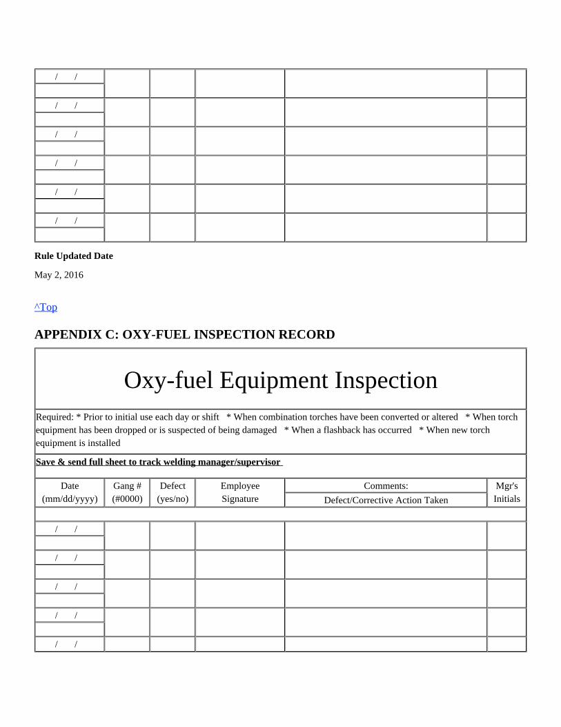
/ /
/ /
/ /
/ /
/ /
/ /
Rule Updated Date
May 2, 2016
^Top
APPENDIX C: OXY-FUEL INSPECTION RECORD
Oxy-fuel Equipment InspectionRequired: * Prior to initial use each day or shift * When combination torches have been converted or altered * When torchequipment has been dropped or is suspected of being damaged * When a flashback has occurred * When new torchequipment is installed
Save & send full sheet to track welding manager/supervisor
Date(mm/dd/yyyy)
Gang #(#0000)
Defect(yes/no)
EmployeeSignature
Comments: Mgr'sInitialsDefect/Corrective Action Taken
/ /
/ /
/ /
/ /
/ /
/ /
/ /
/ /
/ /
/ /
/ /
/ /
/ /
/ /
/ /
/ /
/ /
/ /
Rule Updated Date
May 2, 2016
^Top
APPENDIX D: CONVERSION CHART
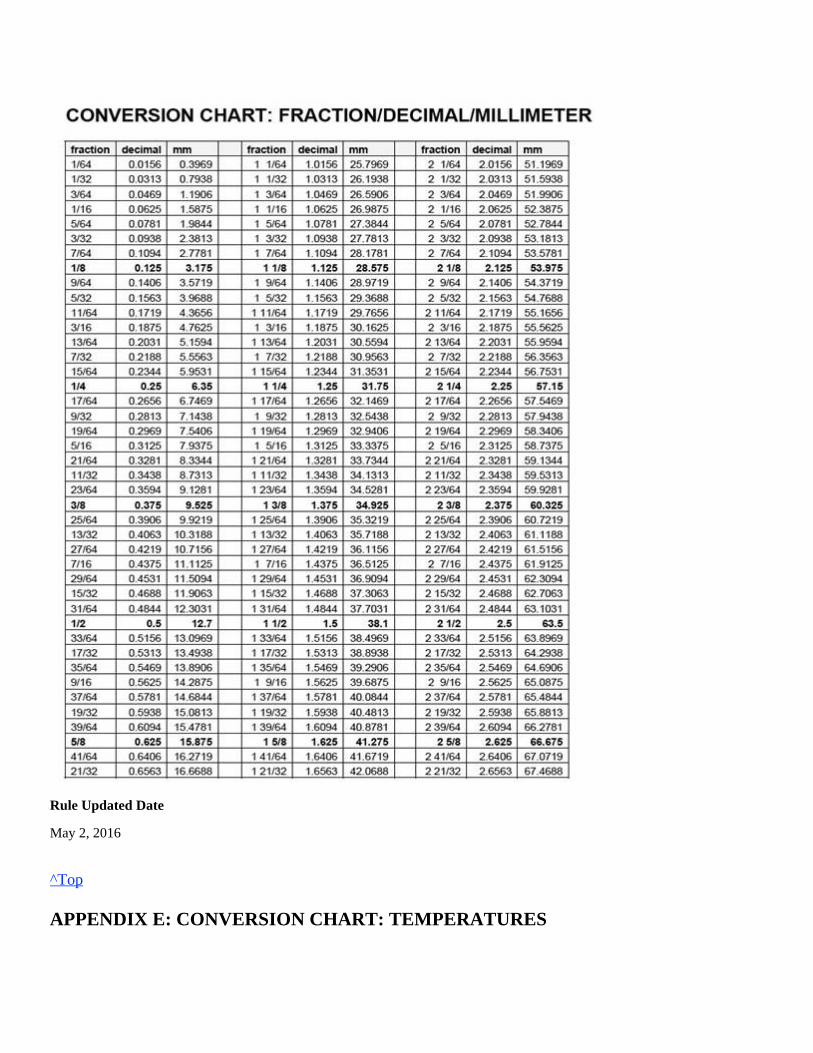
Rule Updated Date
May 2, 2016
^Top
APPENDIX E: CONVERSION CHART: TEMPERATURES
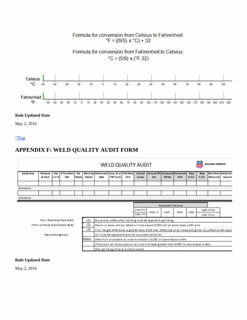
Rule Updated Date
May 2, 2016
^Top
APPENDIX F: WELD QUALITY AUDIT FORM
Rule Updated Date
May 2, 2016

^Top


![Pipe Welding Procedures[1]](https://img.pdfslide.net/doc/110x75/55cf9a13550346d033a05770/pipe-welding-procedures1.jpg)