Embed Size (px)
Citation preview
3308B1 06/26/011
MAINTENANCE INSTRUCTIONM. I. 3308 - Revision B
CA SERIES ALTERNATORSRUNNING MAINTENANCE
AND OVERHAUL INSTRUCTIONS
Service DepartmentELECTRO-MOTIVE DIVISION
GENERAL MOTORS CORPORATIONJune, 2001
SAFETY PRECAUTIONS
Please refer to the EMD Safety Precautions in appendix to the Locomotive ServiceManual whenever routine service or maintenance work is to be performed on any AC
traction equipped locomotive.
The maintenance procedure as outlined in this instruction is specific to CA TypeAlternators and is offered for planning purposes only. As written, this document reflectscurrent EMD product design and service experience for this design. The content of thisM.I. reflects maintenance requirements based on time from delivery or miles in service.This recommendation is consistent with present fleet performance and remains within theEMD experience envelope.

3308B1 06/26/012
This Maintenance Instruction is intended to serve as a guide when establishingmaintenance schedules to meet the particular requirements of individual operationsand planned economic life of the CA Series companion alternator. It providesaverage recommendations, which should ensure satisfactory locomotive operation,and economical maintenance costs where average load factors and climaticconditions are encountered.
The scheduled inspection and maintenance items defined herein are specific to theCA Series Companion Alternators. Component renewal provisions are consistentwith traditional overhaul procedures.
For planning purposes, EMD has established the following overhaul intervalrecommendations for the Companion Alternator. These overhaul intervalrecommendations are based on whichever event occurs first: time, miles, ormegawatt hours.
CA Series Companion Alternators:
• High Speed Service: 8 years / 1,000,000 miles.• Heavy Haul Service: 8 years / 750,000 miles.
Note:Mileage values referenced above are defined by MicroprocessorArchive Data as accumulated by the locomotive control computersystem.
As always, when specific operating conditions severely impact locomotive performance andor reliability, maintenance schedules must be adjusted accordingly.
© Copyright 2001
Electro-Motive Division, General Motors Corporation.
Prepared by International Technical Services – London, Ontario, Canada
All rights reserved. Neither this document, nor any part thereof, may be reprinted withoutthe expressed written consent of the Electro-Motive Division. Contact EMD ServicePublications Office.
3308B1 06/26/013
Table of Contents
1.0 DES CRIPTION...................................................................................................................................................................5
1.1 OPERATION........................................................................................................................................................................ 8
2.0 MAINTENANCE.....................................................................................................................................................................9
2.1 INSPECTION....................................................................................................................................................................... 92.1.1 CABLES AND TERMINAL BOARD........................................................................................................................92.1.2 COLLECTOR RINGS, BRUSHES, AND BRUSH HOLDERS.............................................................................9
2.2 CLEANING........................................................................................................................................................................ 152.2.1 GENERAL...................................................................................................................................................................15
2.3 “SANDING-IN” NEW BRUSHES................................................................................................................................. 162.4 INSULATION RESISTANCE MEASUREMENTS................................................................................................... 17
2.4.1 ROTOR........................................................................................................................................................................172.4.2 STATOR.......................................................................................................................................................................17
3.0 DISASSEMBLY AND OVERHAUL ...............................................................................................................................17
3.1 GENERAL INFORMATION.......................................................................................................................................... 173.2 IDENTIFICATION – D-14 VERSUS CA5 (D-18) ........................................................................................................ 18
3.2.1 STATOR.......................................................................................................................................................................183.2.2 ROTOR........................................................................................................................................................................19
3.3 REMOVING ALTERNATOR STATOR...................................................................................................................... 203.4 REMOVING ALTERNATOR ROTOR........................................................................................................................ 203.5 ROTOR OVERHAUL...................................................................................................................................................... 22
3.5.1 ROTOR CLEANING PRIOR TO VARNISH TREATMENT...............................................................................223.5.2 ROTOR POLE INSPECTION AND TEST............................................................................................................233.5.3 ROTOR REPAIR RECOMMENDATIONS............................................................................................................24
3.6 STATOR OVERHAUL.................................................................................................................................................... 263.6.1 REWIRED STATOR ELECTRICAL WINDING CONNECTION CHECK......................................................303.6.2 STATOR INSULATION RESISTANCE AND HIGH POTENTIAL TEST........................................................313.6.3 PHASE-TO-PHASE RESISTANCE TEST.............................................................................................................313.6.4 STATOR CLEANING PRIOR TO VARNISH TREATMENT..............................................................................31
3.7 ROTOR AND STATOR ASSEMBLY VARNISH TREATMENT......................................................................... 323.7.1 ROTOR ASSEMBLY..................................................................................................................................................323.7.2 ROTOR REPAIR PROCEDURE.............................................................................................................................323.7.3 STATOR ASSEMBLY................................................................................................................................................33
4.0 HI-POT GENERAL INFORMATION ...........................................................................................................................34
4.1 WAVE FORM .................................................................................................................................................................... 344.2 SURGES.............................................................................................................................................................................. 344.3 REGULATION.................................................................................................................................................................. 344.4 SAFETY PRECAUTIONS.............................................................................................................................................. 35
5.0 ALTERNATOR TO GENERATOR ASSEMBLY......................................................................................................35
5.1 ALTERNATOR ROTOR TO GENERATOR ROTOR.............................................................................................. 355.2 ALTERNATOR STATOR TO GENERATOR STATOR......................................................................................... 35
3308B1 06/26/014
6.0 SERVICE DATA………………………………………………………………………………………………...37
6.1 SPECIFICATIONS............................................................................................................................................................ 376.1.1 Brushes (Alternator Only).......................................................................................................................................376.1.2 Output Ratings...........................................................................................................................................................376.1.3 Resistance at 75°C (167°F).....................................................................................................................................386.1.3 Air Gap (nominal)…………………………………………….………....................................................................396.1.4 Weights (Approx.) .....................................................................................................................................................39
6.2 MATERIAL........................................................................................................................................................................ 396.3 TOOLS................................................................................................................................................................................. 40
3308B1 06/26/015
1.0 DESCRIPTION
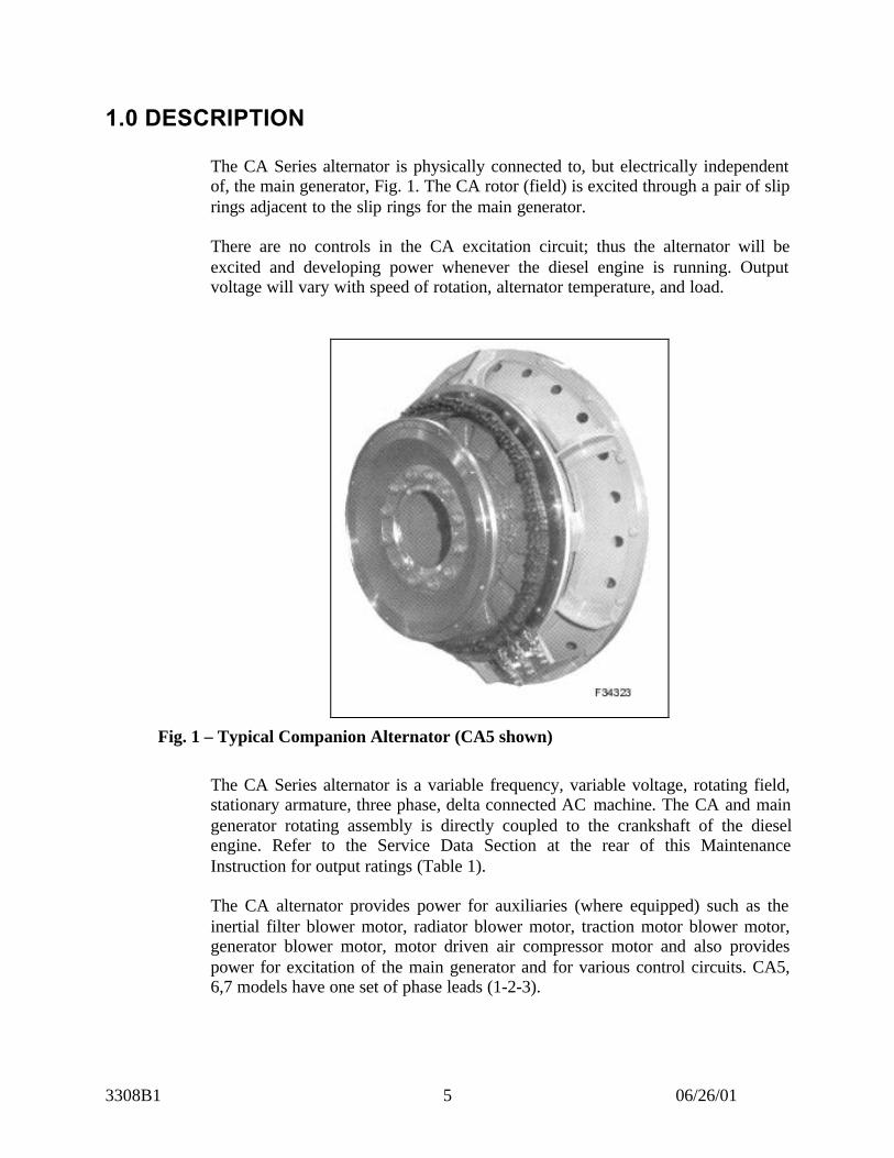
The CA Series alternator is physically connected to, but electrically independentof, the main generator, Fig. 1. The CA rotor (field) is excited through a pair of sliprings adjacent to the slip rings for the main generator.
There are no controls in the CA excitation circuit; thus the alternator will beexcited and developing power whenever the diesel engine is running. Outputvoltage will vary with speed of rotation, alternator temperature, and load.
Fig. 1 – Typical Companion Alternator (CA5 shown)
The CA Series alternator is a variable frequency, variable voltage, rotating field,stationary armature, three phase, delta connected AC machine. The CA and maingenerator rotating assembly is directly coupled to the crankshaft of the dieselengine. Refer to the Service Data Section at the rear of this MaintenanceInstruction for output ratings (Table 1).
The CA alternator provides power for auxiliaries (where equipped) such as theinertial filter blower motor, radiator blower motor, traction motor blower motor,generator blower motor, motor driven air compressor motor and also providespower for excitation of the main generator and for various control circuits. CA5,6,7 models have one set of phase leads (1-2-3).
3308B1 06/26/016
CA8 models have two sets of phase leads with 1-2-3 used for AC electricalequipment and 4-5-6 used for Traction Alternator excitation.
The CA9 models are equipped with three sets of phase leads with 1-2-3 used forAC electrical equipment, 4-5-6 used for Traction Alternator excitation and 7-8-9used for APC 74-volt system (eliminates auxiliary generator).
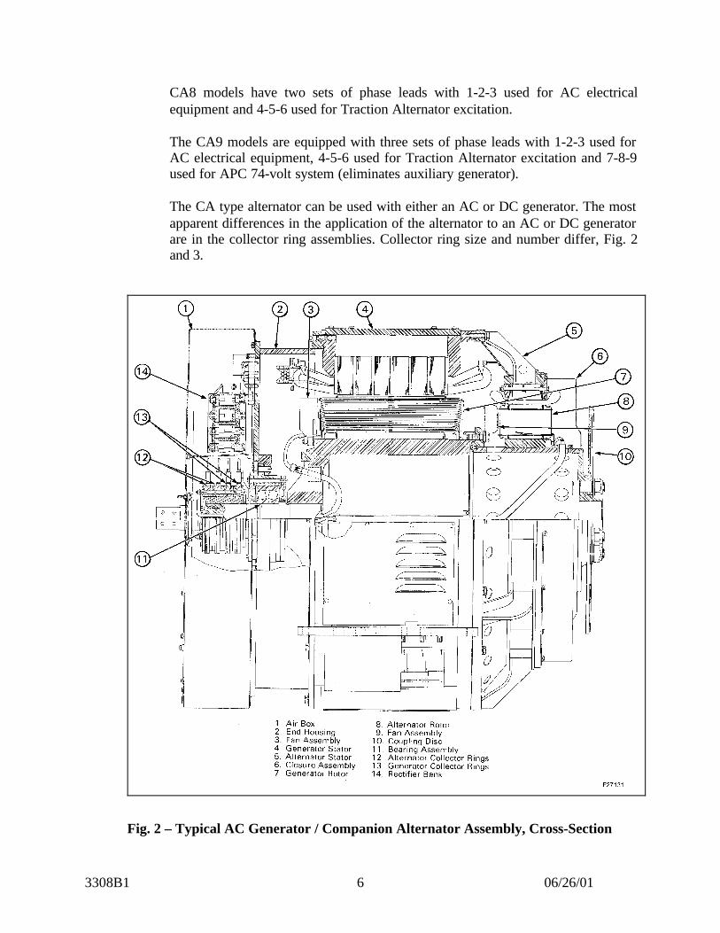
The CA type alternator can be used with either an AC or DC generator. The mostapparent differences in the application of the alternator to an AC or DC generatorare in the collector ring assemblies. Collector ring size and number differ, Fig. 2and 3.
Fig. 2 – Typical AC Generator / Companion Alternator Assembly, Cross-Section
3308B1 06/26/017
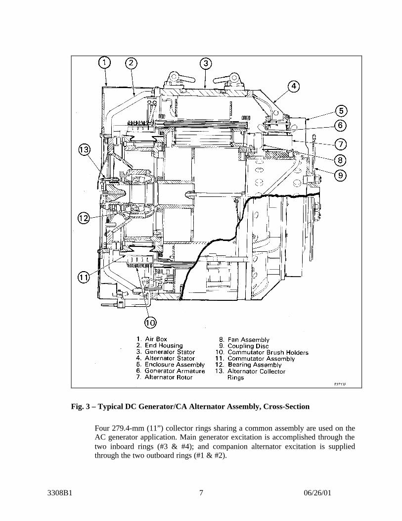
Fig. 3 – Typical DC Generator/CA Alternator Assembly, Cross-Section
Four 279.4-mm (11”) collector rings sharing a common assembly are used on theAC generator application. Main generator excitation is accomplished through thetwo inboard rings (#3 & #4); and companion alternator excitation is suppliedthrough the two outboard rings (#1 & #2).

3308B1 06/26/018
The DC main generator application has only two collector rings and associatedequipment to provide excitation to the alternator. The collector rings areapproximately 236.54 mm (9 – 5/16”). Excitation to the DC generator is providedthrough the commutator and commutator brush assembly.
1.1 OPERATION
The alternator stator assembly is bolted directly to the main generator frame. Therotor or rotating field assembly is bolted at one end to the main generator fieldassembly, and to the engine at the other end by means of a disc type coupling.Refer to Figure 4.
Fig. 4 – AC Generator/ Companion Alternator Assembly (AR10/CA5 shown)
The alternator field circuit consists of 16 field coils connected in series of whicheight are open and eight are closed. The “open and closed” coils alternate. Thusthe series connecting straps do not crisscross on every other coil to get alternatingpolarity.
3308B1 06/26/019
2.0 MAINTENANCE
The alternator should be inspected and cleaned at intervals specified in theapplicable Scheduled Maintenance Program. Operation and service, to which thegenerator is subjected, will determine the extent of maintenance required.
2.1 INSPECTION
2.1.1 CABLES AND TERMINAL BOARD
Ensure tightness of all mechanical and electrical connections. Cable connectionsto the terminal board and brush holders should be intact. Using dry cloths, wipeaway any accumulation of dirt.
2.1.2 COLLECTOR RINGS, BRUSHES, AND BRUSH HOLDERS
The collector rings, Figs. 5 and 6, should be checked frequently while generator isin operation. Eliminate sparking conditions immediately. Normally, the negativering will experience wear more rapidly than the positive ring. To minimize theunequal wear, reverse the ring polarity at six-month intervals.
The following conditions may result in sparking on collector rings:
1. Collector rings not running concentric with shaft.2. Collector ring surface rough or pitted.3. Brushes tight in brush holder.4. Oil on surface of collector ring.5. Vibration of brush holder studs.
If collector ring surfaces are oily, wipe off the surface of the rings and brusheswith a clean, dry, bound edge cloth.
A rough or pitted collector ring surface is usually due to prolonged sparking.Usually this condition can be corrected by grinding.
On the AC generator/alternator installation, collector ring concentricity should bewithin 0.15 mm (.006”) total indicator reading (rings installed on generator), andlateral run-out within 0.8 mm (1/32”). If these tolerances are exceeded, the ringswill have to be machined. The diameter of a new ring is 279.40 mm (11.000”),Fig. 7. The minimum acceptable diameter on the collector rings is 260.35 mm (10– 1/4”). If rough rings cannot be cleaned up without going below the minimumdiameter, they should be replaced.

3308B1 06/26/0110
Fig. 5 – Typical AC Generator/CA Brush Holder and Collector Ring
Fig. 6 – Typical DC Generator/CA Brush Holder and Collector Ring
3308B1 06/26/0111
WARNING!Misapplication of generator and alternator collector ring leads can result incontinuous excitation of the main generator from the alternator field leads.This condition could result in a serious accident when the diesel engine isrunning and placed on the line. If power contactors are picked up, thelocomotive can inadvertently move when the isolation switch is placed in“run” position.
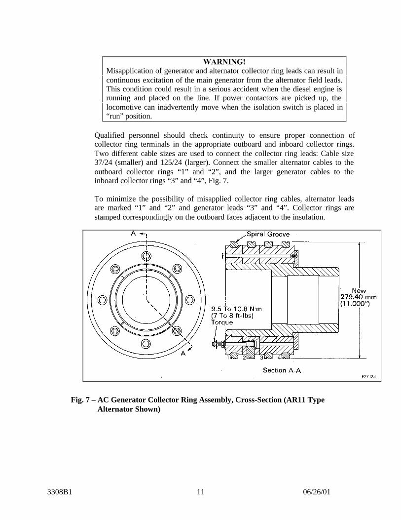
Qualified personnel should check continuity to ensure proper connection ofcollector ring terminals in the appropriate outboard and inboard collector rings.Two different cable sizes are used to connect the collector ring leads: Cable size37/24 (smaller) and 125/24 (larger). Connect the smaller alternator cables to theoutboard collector rings “1” and “2”, and the larger generator cables to theinboard collector rings “3” and “4”, Fig. 7.
To minimize the possibility of misapplied collector ring cables, alternator leadsare marked “1” and “2” and generator leads “3” and “4”. Collector rings arestamped correspondingly on the outboard faces adjacent to the insulation.
Fig. 7 – AC Generator Collector Ring Assembly, Cross-Section (AR11 TypeAlternator Shown)

3308B1 06/26/0112
The DC generator/alternator installation collector rings are smaller, approximately241 mm (9.5”). Collector ring concentricity should be within 0.15 mm (.006”)total indicator reading (rings installed on generator), and lateral run-out within 0.8mm (1/32”). If these tolerances are exceeded, the rings will have to be machinedor stoned. The diameter of a new ring is 236.52 mm (9.312”), Fig. 8. Theminimum acceptable diameter on the collector rings is 225.42 mm (8.875”). Ifrough rings cannot be cleaned up without going below the minimum diameter,they should be replaced.
Fig. 8 – DC Generator Collector Ring Assembly, Cross-Section
Before grinding, remove brush holder assembly, and install the grinder andadapter to the applicable tapped holes or studs provided. Reference Service Datafor grinding equipment.
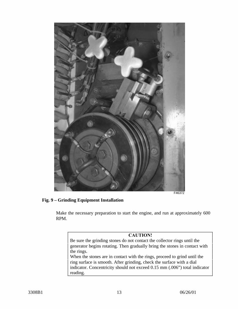
Position the grinder so there will be 3-mm (1/8”) clearance between it and therings to be ground. Install grinding stones in position on the grinder, makingcertain there will be enough travel to grind the rings. Figure 9 shows the grindingequipment in place.
3308B1 06/26/0113
F46372
Fig. 9 – Grinding Equipment Installation
Make the necessary preparation to start the engine, and run at approximately 600RPM.
CAUTION!Be sure the grinding stones do not contact the collector rings until thegenerator begins rotating. Then gradually bring the stones in contact withthe rings.When the stones are in contact with the rings, proceed to grind until thering surface is smooth. After grinding, check the surface with a dialindicator. Concentricity should not exceed 0.15 mm (.006”) total indicatorreading.
3308B1 06/26/0114
When the grind operation is complete, remove the grinding equipment. Blow outall grinding dust and reassemble the brush holder assembly in its proper position.Renew brushes if necessary, and follow instructions given under “Sanding-In”New Brushes.
CAUTION!Because of the continued abrasive action, do not use emery cloth forpolishing collector rings.
The spring pressure of the brush holders is preset and remains constant throughoutthe brush life regardless of wear.
Main generator brush spring pressure is 1.5 kg. (3.3 lbs.). CA brush springpressure is 0.68 kg. (1.5 lbs.).
AC generators are equipped with eight constant pressure brush holders, Fig. 5,page 10, four mounted at the top of the collector ring assembly and four at thebottom. The brushes riding on the two inside collector rings are for the maingenerator and the two riding on the two outside collector rings are for thealternator.
NOTEIn certain applications there are 10 brushes, six for the main alternator andfour for the CA5 alternator. The two extra holders are for the higher fieldcurrent required in the main generator. These models include: AR17(GP60), AR20 (SD70/75), TA17 (SD70MAC), TA20 (SD90MAC PhaseII), TA22 (SD80/90MAC).
DC generators are equipped with four constant pressure brush holders, Fig. 6,page 10, two mounted at the top of the collector ring assembly and two at thebottom. The brushes riding on the collector rings are for the CA5 alternator.These alternator brushes are the same as those above having 0.68 kg. (1.5 lbs.)spring pressure. The main generator excitation is provided through thecommutator and commutator brushes.
Ensure brush holder support bolts are tight to eliminate possible vibration.
3308B1 06/26/0115
2.2 CLEANING
2.2.1 GENERAL
If alternator is not disassembled, do not clean with a liquid cleaner. Drycompressed air at low pressure 207-345 kPa (30-50 psi) may be used to blow outdirt from the stator and rotor assembly.
CAUTION!Do not use high air pressure since there is danger of loosening theinsulation binding and blowing particles which may damage theinsulation.
Where the use of low air pressure and dry cloths proves ineffective in removingimbedded deposits of dirt, a stiff brush, soft wood, or fiber scrapers may be used.In severe cases (to prevent surface creepage), dampen a cloth in solvent such asStoddards Solvent to loosen and remove the dirt from rotating field terminals andconnectors.
CAUTION!Ensure there is adequate ventilation and safety precautions are observedwhen handling inflammable fluids such as Stoddards Solvent, which has aflash point of 46°C (115°F).
After cleaning, paint connectors and field coil connections with red air dryingenamel. When enamel has dried, apply black air drying varnish. Refer to ServiceData for red air drying enamel and black air drying varnish part number.
3308B1 06/26/0116
2.3 “SANDING-IN” NEW BRUSHES
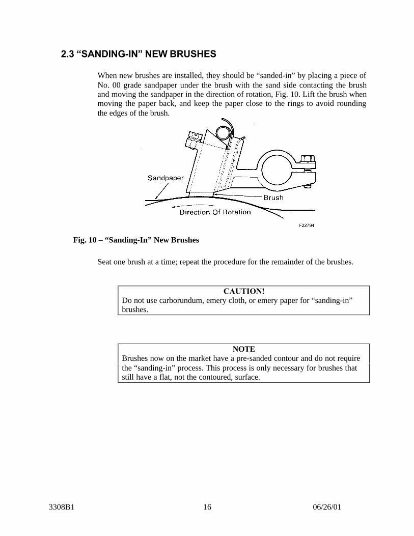
When new brushes are installed, they should be “sanded-in” by placing a piece ofNo. 00 grade sandpaper under the brush with the sand side contacting the brushand moving the sandpaper in the direction of rotation, Fig. 10. Lift the brush whenmoving the paper back, and keep the paper close to the rings to avoid roundingthe edges of the brush.
Fig. 10 – “Sanding-In” New Brushes
Seat one brush at a time; repeat the procedure for the remainder of the brushes.
CAUTION!Do not use carborundum, emery cloth, or emery paper for “sanding-in”brushes.
NOTEBrushes now on the market have a pre-sanded contour and do not requirethe “sanding-in” process. This process is only necessary for brushes thatstill have a flat, not the contoured, surface.
3308B1 06/26/0117
2.4 INSULATION RESISTANCE MEASUREMENTS
Using a megger, make an insulation resistance test on the rotor and stator. Thisshould be done prior to making the high potential test. Readings of one megohmor better are satisfactory.
2.4.1 ROTOR
Field coil terminals and connectors should be thoroughly cleaned on both sidesprior to making an insulation test. A low reading is likely to result if this is notdone.
To test the rotor insulation, isolate the winding by lifting all the brushes off thecollector rings. Connect the megohmmeter round lead to the generator rotor orengine flywheel rather than to the frame of the machine. The other lead isconnected to the collector ring.
2.4.2 STATOR
Connecting the megger ground lead to the alternator frame and the other lead tothe stator winding being tested checks the stator insulation. Be sure insulationresistance of the line cables to AC cabinet is not included.
3.0 DISASSEMBLY AND OVERHAUL
3.1 GENERAL INFORMATION
The alternator assembly should be removed from the generator and overhauled atintervals specified in the Scheduled Maintenance Program.
Overhaul consists of disassembly, major component inspection and cleaning, andreplacement of worn or defective parts. Special processing to ensure adequatedielectric strength of components is ensured by the specified varnish treatment.
NOTEInsulation naturally deteriorates from the adverse affects of age, dirt, heat,and moisture. Deterioration can be slowed by proper service and care.
3308B1 06/26/0118
Equipment tested and approved after overhaul should perform satisfactorilybetween scheduled overhaul periods.
CAUTION!Ensure that different types of rotors and stators are not mixed in onemachine.
3.2 IDENTIFICATION – D-14 Versus CA5 (D-18)
The CA5 and D14 stators are both “form” wound which makes them virtuallyidentical in appearance. The D18 stator, however, is “random” wound whichmakes it more easily distinguished from either the D14 or the CA5 stators.Moreover, all three of these stators fit within the same dimension outer frame,which makes it especially important that the correct stator be matched to thecorrect rotor.
The proper stators and rotors can be identified in the following ways:
3.2.1 STATOR
1. The serial number and model (CA or D) are stamped on the nameplate appliedto the outer frame. This number, however, can be misleading if a differentstator was installed in the outer frame without changing the number stampedon it.
2. Verify the stator resistance values as per Table 1 in the Service Data Section ofthis M.I.
3. Phase lead markings as shown in Fig. 11, page 19.
NOTEThe CA5 has 14 phase leads compared to 12 on the D14. Phase leads 5 – 2and 4 – 2 have two leads connected to one terminal as shown in the sketchof the CA5. Also, the CA5 phase leads are connected to the first and thirdrow of terminals on the 12 point terminal boards, whereas, the D14 usesthe first and second row of terminals.

3308B1 06/26/0119
Fig. 11 – CA5 Alternator and D14 Alternator
3.2.2 ROTOR
The resistance values of a complete rotor assembly may be verified using Table 1 inthe Service Data Section of this M.I.
The lamination stack length is as follows:
a. D14 – 5 in.b. CA5 (D18) – 6 – 3/32 in.
The two rotor poles are shown below:
Fig. 12 – Rotor Pole Comparison

3308B1 06/26/0120
3.3 REMOVING ALTERNATOR STATOR
To remove the alternator stator from the generator frame, proceed as follows.Refer to Fig. 3 or 4 as applicable.
1. Remove generator coupling disc and alternator stator closure assembly.
2. Support alternator stator with a crane and a steel cable through a clevis pinnedin the hole in the top center rib of the alternator stator frame.
3. Remove bolts holding alternator stator frame to generator (stator) frame.
4. Install three 1/2” – 13 jacking bolts in the tapped holes provided in thealternator stator frame. Rotate jacking bolts evenly, taking care to avoidbinding.
5. Remove alternator stator over alternator rotor poles. Handle with care toprevent damage to laminations or windings.
3.4 REMOVING ALTERNATOR ROTOR
Perform the following procedure to remove the alternator rotor from maingenerator after the alternator stator has been removed. Refer to Figs. 3 or 4 asapplicable.
1. Disconnect the leads at the collector ring terminal posts.
2. Remove the shaft flange and conduit busing at the collector ring end of theshaft.
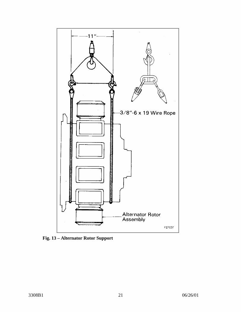
3. Support the alternator rotor using an alternator rotor-lifting sling, as shown inFig. 12, and a crane. Refer to Service Data for file Drawing number of sling.
4. Remove bolts connecting alternator rotor to the generator rotor.
5. Place jacking screws in the holes provided and remove alternator rotor.
3308B1 06/26/0121
Fig. 13 – Alternator Rotor Support

3308B1 06/26/0122
3.5 ROTOR OVERHAUL
Perform the following procedures as applicable, to repair or overhaul thealternator rotor.
3.5.1 ROTOR CLEANING PRIOR TO VARNISH TREATMENT
After separating the alternator rotor from the generator rotor, perform either of thefollowing cleaning procedures in preparation for varnish treatment. Position therotor to allow access to all areas during the cleaning process.
3.5.1.1 WET METHOD
The rotor may be cleaned with a steam cleaner such as Dober ChemicalCorporation Cleaner 6006 or Turco Chemical Company Steamfas.
Use an 85 g per 3.79 liter (3 oz./gal.) mixture of cleaner and water and maintain atank temperature of approximately 60° C to 71° C (140°F to 160°F).
WARNING!Protect skin and clothing while steam cleaning. Operator should wearrubber apron, boots, gloves, and a plastic face shield.
Steam clean the stator assembly as follows.
NOTEThe solution tank should be approximately 0.9 m x 1.2 m x 0.9 m (3’ x 4’x 3’). Two steam guns are required such as Hurriclean Steam Guns, Model551.
1. Regulate a No. 1 steam gun to obtain a good soapy solution.
2. Steam clean stator holding No. 1 steam gun nozzle at an angle to the statorabout 100 mm to 150 mm (4” to 6”) away.
3. Rinse the stator thoroughly using a No. 2 steam gun with a combination ofclean water and steam to remove all traces of cleaner.
4. Blow off stator using high volume, low pressure, clean, dry, compressed air.
5. Thoroughly dry rotor by placing in an oven at a regular temperature of 150° C(302°F) for 8 hours.
3308B1 06/26/0123
3.5.1.2 DRY METHOD
An alternate, satisfactory cleaning method employs the use of granulated corncobmaterial applied with a controlled air blast. This method produces a clean, oil freesurface ready for immediate varnish treatment.
When using this method, care should be exercised, as it is possible to removevarnish and cut into the layers of insulation by prolonged application of the blastmaterial. Pressure used should be between 300 to 400 kPa (45 to 60 psi).
The corn cob material trapped in the pockets or crevices of the rotor should beremoved by a straight air blast at reduced air pressure.
3.5.2 ROTOR POLE INSPECTION AND TEST
3.5.2.1 LOOSE POLE CHECK
1. Inspect pole connectors for fatigue cracks, faulty connections, or burnedinsulation. A broken coil-connecting strap will be evident by an open alternatorfield circuit and most likely indicates a loose pole.
2. Closely examine the area between pole piece and spider. A rust-like substanceindicates a fretting condition.
3. Perform a pole tap test by tapping pole piece with a copper bar or lead mallet,while at the same time, holding a finger at the point between the pole and thespider. Movement indicates looseness at this point. Do not tap coil orinsulation. Refer to Repair Recommendations section of this MaintenanceInstruction if loose pole pieces are found.
3.5.2.2 ROTOR INSULATION RESISTANCE AND HIGH POTENTIAL TEST
Perform an insulation resistance test to field winding circuit with a megger.Megger indication of 15 megohms minimum is satisfactory for hi-pot test.
If megger indication is less than 15 megohms, bake the rotor in an oven at 130°C± 10° (266°F ± 18°) to remove any moisture which may be causing lowindication. Repeat megger test when the rotor is at room temperature. If meggerindication is 15 megohms or better, proceed with hi-pot test. If indication is below15 megohms, disconnect connector straps and use megger to locate defectivecoil(s). Replace any defective coil with a serviceable coil.
Perform hi-pot test to ground at 1700 volts for 10 seconds on new and 1000 voltsfor 10 seconds on used machines.

3308B1 06/26/0124
NOTEThe connector blocks have unusual insulation resistance characteristics;this must be considered when interpreting megger readings. If a meggerindication is less than 15 megohms on a clean rotor, the coil terminalshould be disconnected from the block and the individual coils meggeredto ground. Individual coil readings should be 250 megohms or more. If so,reconnect the coil to the blocks, and perform the hi-pot test. Refer to Hi-Pot General Information prior to performing test.
3.5.3 ROTOR REPAIR RECOMMENDATIONS
1. If there are any broken rotor pole studs, or if the studs should break during thetightening process, renew all pole studs for that particular pole.
2. To tighten rotor pole assembly, torque each 5/8-18 pole stud/nut to a minimumof 237.27 – 264.38 N•m (175-195ft. – lbs.). Rap the pole piece head sharplywith a lead or copper mallet, and again torque each pole stud/nut to 237.27 –264.38 N•m (175-195 ft. – lbs.). Note: For CA8 rotor coil 7/8-14 bolts performthe same torque sequence, but torque to 684.69 – 711.80 N•m (505-525 ft lbs).
To replace a pole piece assembly, proceed as follows:
1. Remove the defective pole assembly.
2. Install proper new pole assembly with new studs. There are eight open andeight crossed alternator field coil assemblies, Fig. 14. These field coilassemblies should be installed so no two like assemblies are adjacent.
Apply thread lubricant, such as Texaco Threadtex No. 2303, to pole studs at timeof installation. Refer to Service Data for thread lubricant part number.
3. Perform a polarity test of the rotor poles as follows:
a. Apply 15 volts to rotor field coil circuit.
b. Hold compass at center of a rotor coil. Compass should indicate a northor south pole indication. Move compass from pole to pole. Each coilshould indicate a definite change in polarity. If compass does notindicate a polarity change, either two poles of the same polarity arepositioned next to each other or there is a wrong connection at theconnector blocks. Replace wrong coil with proper coil or repairdefective connection.

3308B1 06/26/0125
NOTEWhen installing a new pole assembly, it is advisable to match the weightof the pole being replaced as closely as possible to simplify balancing.
4. Check poles for spacing and parallelism. Measure the distance between poles,on the sides of the laminations, half way between the brass end pieces. Avariation of 0.8 mm (1/32”) between maximum and minimum readings isallowed on this dimension. Pole axis should be parallel with the main rotor axiswithin 0.8 mm (1/32”) in the length of the laminations. Maintain a 1.6-mm(1/16”) clearance between the coil surfaces of any two adjacent poles. Refer toFig. 14.
Fig. 14 – CA Type Alternator Rotor Pole Assembly
5. Torque each pole stud to 251 N•m ± 14 (185 ft. – lbs. ± 10).
6. It is recommended that the cables to field coils be replaced whenever the rotoris being overhauled.
3308B1 06/26/0126
7. Whenever a pole assembly has been removed, or one or more new poles havebeen replaced, the rotor assembly should be dynamically balanced within 0.056N•m (8-in. oz.).
8. High potential test the entire field coil circuit to ground at 1700 VAC for 10seconds on new and 1000 volts AC for 10 seconds on used machines.
WARNING!Insulate the end of the two cables to prevent injury to personnel.
9. Resistance test entire field coil circuit using at least 8 amperes through the fieldcoils. Compare resistance values with Table 1 in the Service Data Section.
10. Paint cable connections, bolts, and nuts, inside of spider, plate, and conduitwith red air drying enamel. Take care to keep enamel off all finished surfaces.
3.6 STATOR OVERHAUL
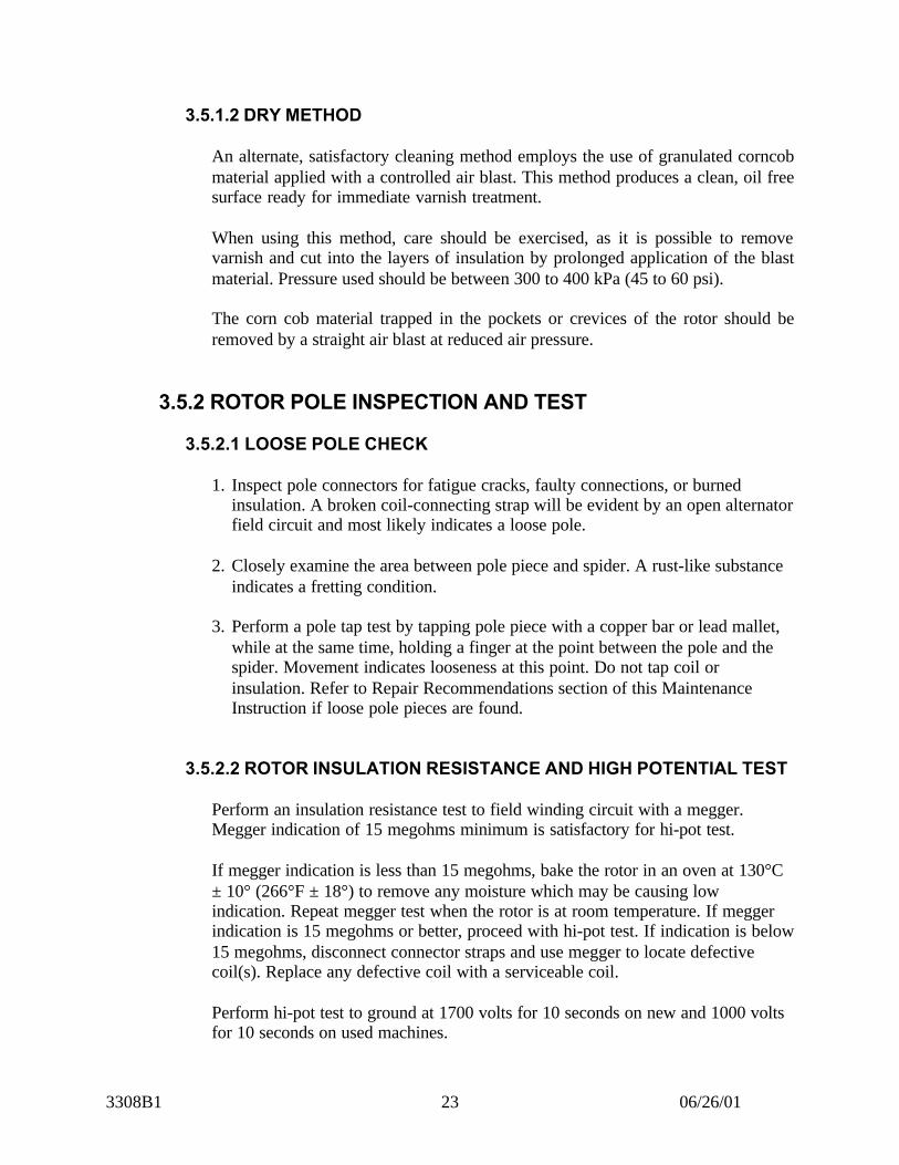
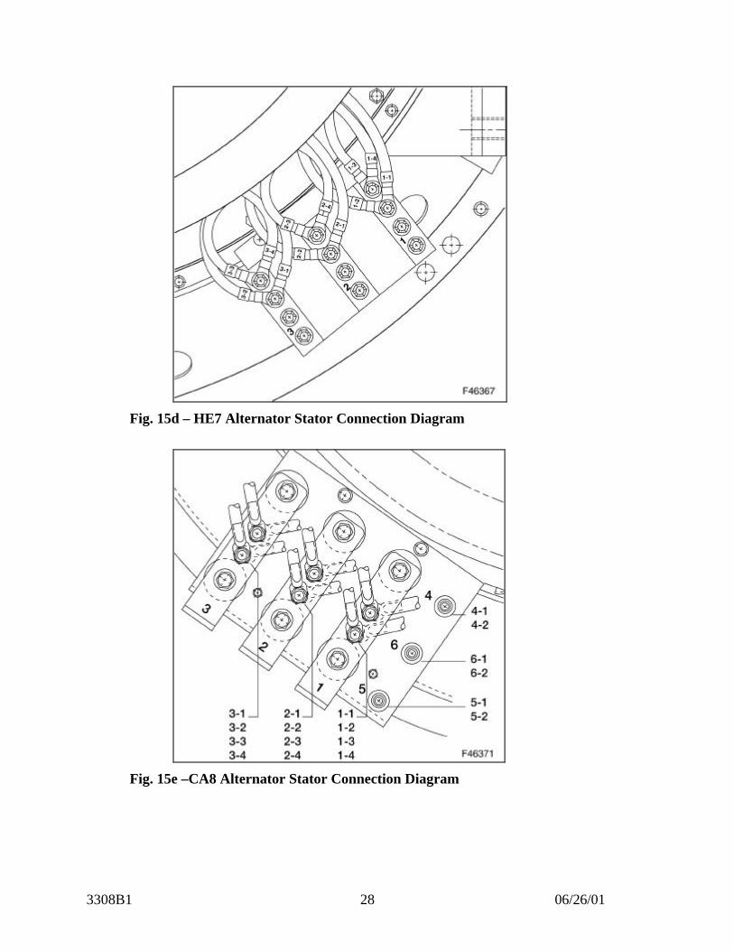
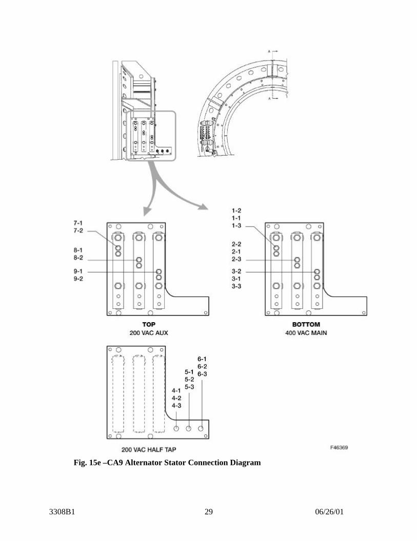
The alternator stator is connected to the terminal bus bars as shown in Figures 15athrough 15e.
Fig. 15a – CA5 Alternator Stator Connection Diagram
3308B1 06/26/0127
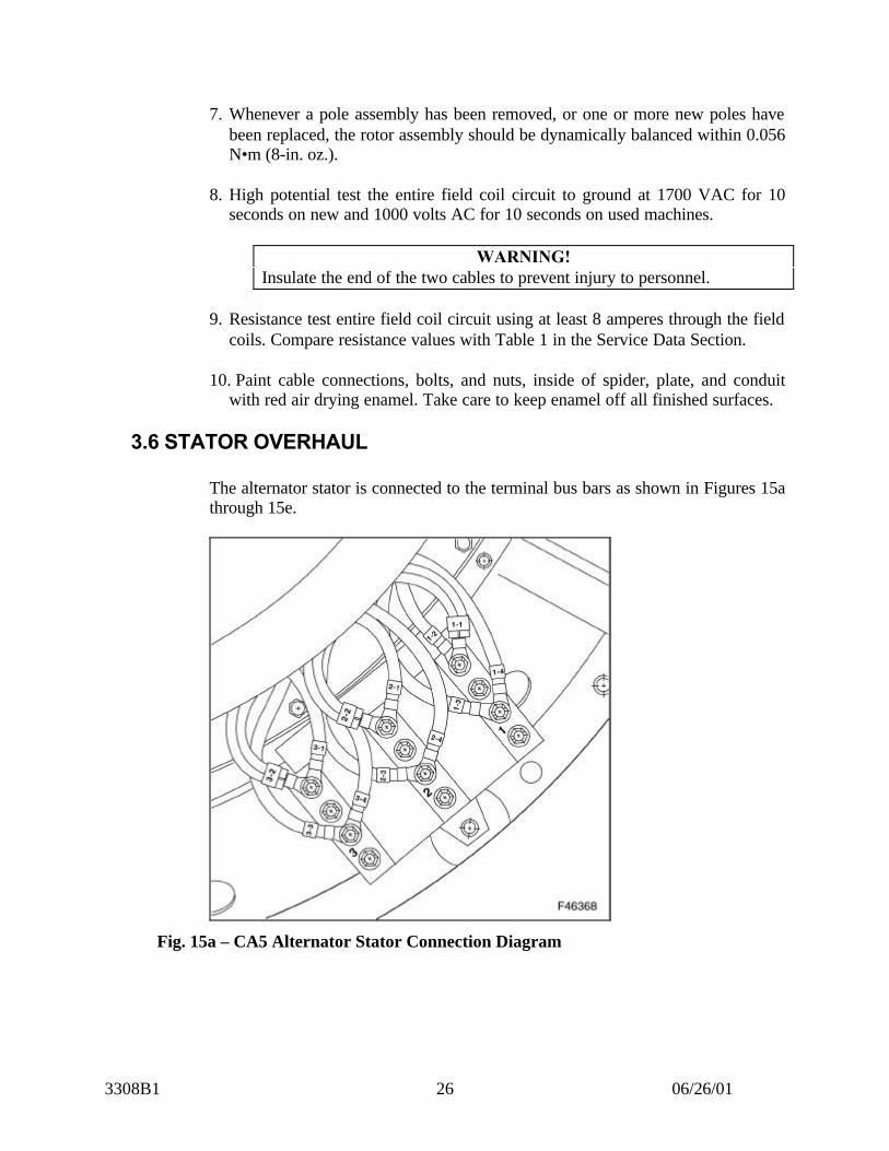
Fig. 15b – CA6 Alternator Stator Connection Diagram
Fig. 15c – CA7 Alternator Stator Connection Diagram
3308B1 06/26/0128
Fig. 15d – HE7 Alternator Stator Connection Diagram
Fig. 15e –CA8 Alternator Stator Connection Diagram
3308B1 06/26/0129
Fig. 15e –CA9 Alternator Stator Connection Diagram
3308B1 06/26/0130
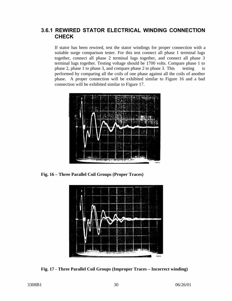
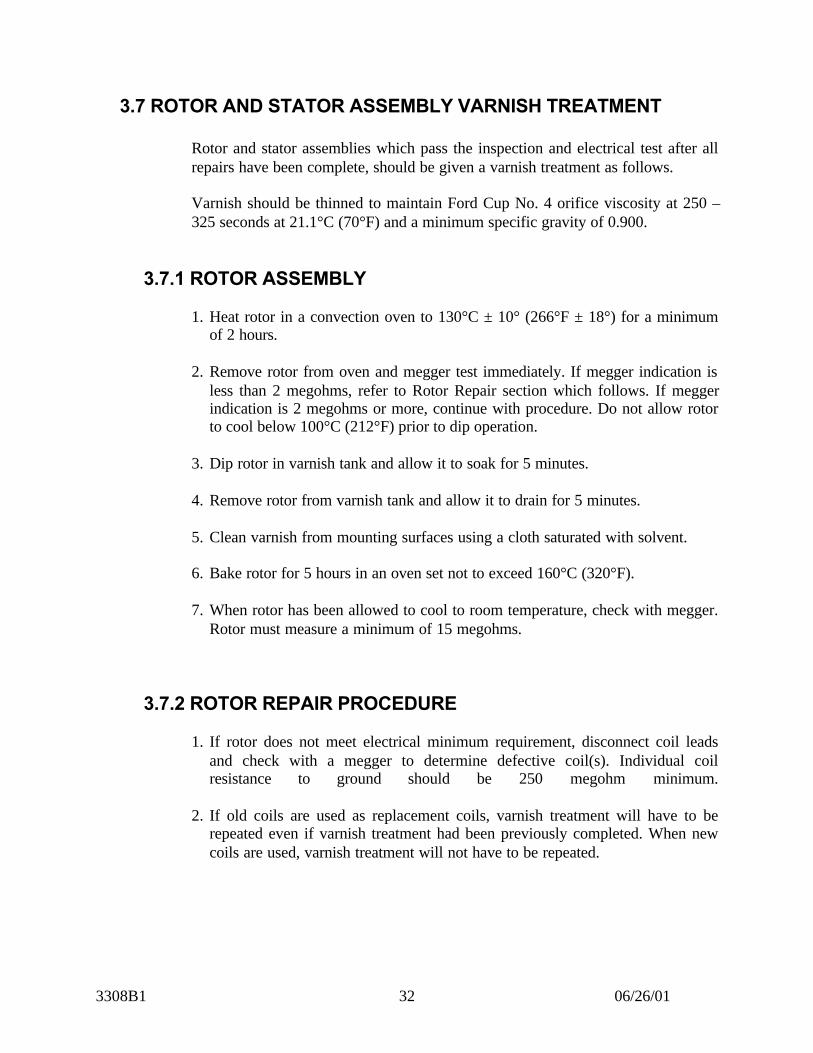
3.6.1 REWIRED STATOR ELECTRICAL WINDING CONNECTIONCHECK
If stator has been rewired, test the stator windings for proper connection with asuitable surge comparison tester. For this test connect all phase 1 terminal lugstogether, connect all phase 2 terminal lugs together, and connect all phase 3terminal lugs together. Testing voltage should be 1700 volts. Compare phase 1 tophase 2, phase 1 to phase 3, and compare phase 2 to phase 3. This testing isperformed by comparing all the coils of one phase against all the coils of anotherphase. A proper connection will be exhibited similar to Figure 16 and a badconnection will be exhibited similar to Figure 17.
Fig. 16 – Three Parallel Coil Groups (Proper Traces)
Fig. 17 - Three Parallel Coil Groups (Improper Traces – Incorrect winding)

3308B1 06/26/0131
3.6.2 STATOR INSULATION RESISTANCE AND HIGH POTENTIALTEST
Perform an insulation and resistance test to the stator windings using a megger. Ifmegger indicates less than 2 megohms, bake stator in an oven at 125°C (257°F)for 4 hours, to remove any moisture. If minimum of 2 megohms is obtained,proceed with high potential test.
Perform high potential test to ground at 1500 volts for 10 seconds on new and1000 volts for 10 seconds on used machines.
3.6.3 PHASE-TO-PHASE RESISTANCE TEST
Perform a phase-to-phase resistance test between the stator terminals. Ensure thereadings taken are compared with the appropriate model listed in Table 1 of theService Data Section.
On CA5, 6, and 7 machines, measure the resistance between terminals 1 and 2,terminals 2 and 3, and terminals 1 and 3.
For CA8 machines, measure the resistance between terminals 1 and 2, terminals 2and 3, terminals 1 and 3, terminals 4 and 5, terminals 5 and 6, and terminals 4 and6.
For CA9 machines, measure the resistance between terminals 1 and 2, terminals 2and 3, terminals 1 and 3, terminals 4 and 5, terminals 5 and 6, terminals 4 and 6,terminals 7 and 8, terminals 8 and 9, and terminals 7 and 9.
3.6.4 STATOR CLEANING PRIOR TO VARNISH TREATMENT
Clean stator with granulated corn cob material applied with a controlled air blast.This method produces a clean, oil free surface ready for immediate varnishtreatment.
Care should be exercised, as it is possible to remove varnish and cut into layers ofinsulation material.
Pressure used should be between 300 to 400 kPa (45 to 60 psi).
The corn cob material trapped in the pockets or crevices of the stator should beremoved by a straight air blast at reduced air pressure.
Cover terminal lugs with friction tape to prevent varnish from getting on terminallugs.
3308B1 06/26/0132
3.7 ROTOR AND STATOR ASSEMBLY VARNISH TREATMENT
Rotor and stator assemblies which pass the inspection and electrical test after allrepairs have been complete, should be given a varnish treatment as follows.
Varnish should be thinned to maintain Ford Cup No. 4 orifice viscosity at 250 –325 seconds at 21.1°C (70°F) and a minimum specific gravity of 0.900.
3.7.1 ROTOR ASSEMBLY
1. Heat rotor in a convection oven to 130°C ± 10° (266°F ± 18°) for a minimumof 2 hours.
2. Remove rotor from oven and megger test immediately. If megger indication isless than 2 megohms, refer to Rotor Repair section which follows. If meggerindication is 2 megohms or more, continue with procedure. Do not allow rotorto cool below 100°C (212°F) prior to dip operation.
3. Dip rotor in varnish tank and allow it to soak for 5 minutes.
4. Remove rotor from varnish tank and allow it to drain for 5 minutes.
5. Clean varnish from mounting surfaces using a cloth saturated with solvent.
6. Bake rotor for 5 hours in an oven set not to exceed 160°C (320°F).
7. When rotor has been allowed to cool to room temperature, check with megger.Rotor must measure a minimum of 15 megohms.
3.7.2 ROTOR REPAIR PROCEDURE
1. If rotor does not meet electrical minimum requirement, disconnect coil leadsand check with a megger to determine defective coil(s). Individual coilresistance to ground should be 250 megohm minimum.
2. If old coils are used as replacement coils, varnish treatment will have to berepeated even if varnish treatment had been previously completed. When newcoils are used, varnish treatment will not have to be repeated.
3308B1 06/26/0133
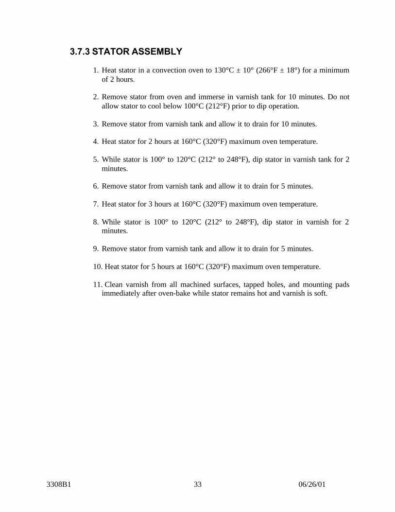
3.7.3 STATOR ASSEMBLY
1. Heat stator in a convection oven to 130°C ± 10° (266°F ± 18°) for a minimumof 2 hours.
2. Remove stator from oven and immerse in varnish tank for 10 minutes. Do notallow stator to cool below 100°C (212°F) prior to dip operation.
3. Remove stator from varnish tank and allow it to drain for 10 minutes.
4. Heat stator for 2 hours at 160°C (320°F) maximum oven temperature.
5. While stator is 100° to 120°C (212° to 248°F), dip stator in varnish tank for 2minutes.
6. Remove stator from varnish tank and allow it to drain for 5 minutes.
7. Heat stator for 3 hours at 160°C (320°F) maximum oven temperature.
8. While stator is 100° to 120°C (212° to 248°F), dip stator in varnish for 2minutes.
9. Remove stator from varnish tank and allow it to drain for 5 minutes.
10. Heat stator for 5 hours at 160°C (320°F) maximum oven temperature.
11. Clean varnish from all machined surfaces, tapped holes, and mounting padsimmediately after oven-bake while stator remains hot and varnish is soft.

3308B1 06/26/0134
4.0 HI-POT GENERAL INFORMATION
It is extremely important that the high potential test equipment be reliable toensure adequate testing without unnecessarily overstressing the insulation.
In regard to the features that should be incorporated in the tester, the followingpoints are pertinent: wave forms, surges, and voltage regulation.
4.1 WAVE FORM
Voltages specified in high potential testing are, unless otherwise specified, root-mean-square (RMS) voltages. The wave form should have a limit of 5% thirdharmonic. This limitation fixes the peak voltage for any RS voltage.
Waveform may be influenced by the capacity of the testing apparatus usedrelative to the size of the piece of equipment being tested. A serious peak on thevoltage wave may result if the test box being used is too small for the piece ofequipment tested. Also, it is possible that the leakage and charging current may besufficient to trip the relay when testing a piece of equipment with a test box whichis too small.
4.2 SURGES
Harmful surges may occur if special attention is not paid to the method ofchanging voltages on the primary when testing.
4.3 REGULATION
Specifications for regulation of high potential equipment state that the secondaryvoltage drop should not exceed 20% under actual test conditions.

3308B1 06/26/0135
4.4 SAFETY PRECAUTIONS
WARNING!ELECTRICAL RATINGS of the test equipment are values that should beconsidered EXTREMELY DANGEROUS to personnel.
The following safety considerations should be carefully observed whenperforming hi-pot tests:
1. Except for the person performing the hi-pot test, all personnel should maintaina safe distance from equipment being tested before applying voltage.
2. Do not make or break the high voltage circuit with the electrodes. Dangerousover-voltage surges may result.
5.0 ALTERNATOR TO GENERATOR ASSEMBLY
5.1 ALTERNATOR ROTOR TO GENERATOR ROTOR
Bolt the alternator rotor to the generator rotor using the 7/8” – 9 bolts removedduring disassembly. Ensure the alternator rotor leads are threaded through thegenerator rotor shaft. Torque the bolts to 813.49 N•m (600 ft.-lbs.).
5.2 ALTERNATOR STATOR TO GENERATOR STATOR
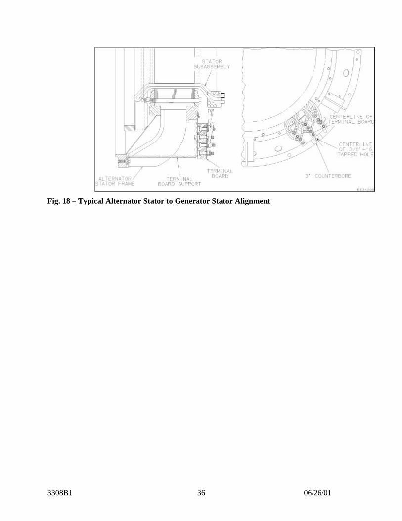
Bolt the alternator stator to the generator stator using the 3/4” – 10 bolts removedduring disassembly. Ensure correct holes in the alternator stator ring line up withmating holes in the generator stator frame. The centerline of the 3/8” – 16 NCtapped hole, which is centered in a 76 mm (3”) counterbore in the outer flange ofthe alternator stator, must line up with the centerline of the terminal board on thegenerator frame, Fig. 18, page 36. Torque bolts to 271 N•m (200 ft.-lbs.).
3308B1 06/26/0136
Fig. 18 – Typical Alternator Stator to Generator Stator Alignment
3308B1 06/26/0137
6.0 SERVICE DATA
6.1 SPECIFICATIONS
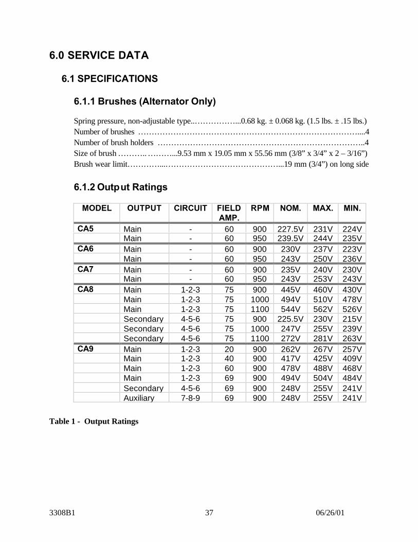
6.1.1 Brushes (Alternator Only)
Spring pressure, non-adjustable type..……………...0.68 kg. ± 0.068 kg. (1.5 lbs. ± .15 lbs.)Number of brushes ………………………………………………………………………....4Number of brush holders …………………………………………………………………..4Size of brush ………..………...9.53 mm x 19.05 mm x 55.56 mm (3/8” x 3/4” x 2 – 3/16”)Brush wear limit…………...……………………………………...19 mm (3/4”) on long side
6.1.2 Output Ratings
MODEL OUTPUT CIRCUIT FIELDAMP.
RPM NOM. MAX. MIN.
CA5 Main - 60 900 227.5V 231V 224VMain - 60 950 239.5V 244V 235V
CA6 Main - 60 900 230V 237V 223VMain - 60 950 243V 250V 236V
CA7 Main - 60 900 235V 240V 230VMain - 60 950 243V 253V 243V
CA8 Main 1-2-3 75 900 445V 460V 430VMain 1-2-3 75 1000 494V 510V 478VMain 1-2-3 75 1100 544V 562V 526VSecondary 4-5-6 75 900 225.5V 230V 215VSecondary 4-5-6 75 1000 247V 255V 239VSecondary 4-5-6 75 1100 272V 281V 263V
CA9 Main 1-2-3 20 900 262V 267V 257VMain 1-2-3 40 900 417V 425V 409VMain 1-2-3 60 900 478V 488V 468VMain 1-2-3 69 900 494V 504V 484VSecondary 4-5-6 69 900 248V 255V 241VAuxiliary 7-8-9 69 900 248V 255V 241V
Table 1 - Output Ratings

3308B1 06/26/0138
6.1.3 Resistance at 75°C (167°F)
Use the following formula to convert resistance measured at any temperature toresistance at 75°C (167°F):
Resistance at 75°C = measured resistance x 309.5234.5 + temperature of item being tested in °C
Model Test Nominal Maximum MinimumCA5 Rotor
(slip ring to slip ring)1.51 1.54 1.48
Stator(phase to phase)
.00355 .00370 .00340
Maximum VariationBetween 2 phases
.00004
CA6 Rotor(slip ring to slip ring)
1.51 1.54 1.48
Stator(phase to phase)
.00425 .00435 .00415
Maximum VariationBetween 2 phases
.00004
CA7 Rotor(slip ring to slip ring)
1.405 1.440 1.370
Stator(phase to phase)
.002285 .00233 .00224
Maximum VariationBetween 2 phases
.00003
CA8 Rotor(slip ring to slip ring)
1.16 1.19 1.13
Stator 1-2-3(phase to phase)
.00570 .00600 .00540
Stator 4-5-6(phase to phase)
.00430 .00460 .00400
Maximum VariationBetween 2 phases
.00030
CA9 Rotor(slip ring to slip ring)
1.57 1.180 1.134
Stator 1-2-3(phase to phase)
.00933 .00952 .00914
Stator 4-5-6(phase to phase)
.00517 .00527 .00507
Stator 7-8-9(phase to phase)
.00758 .00781 .00735
Maximum VariationBetween 2 phases
.00010
Table 2 – Alternator Resistance Values
3308B1 06/26/0139
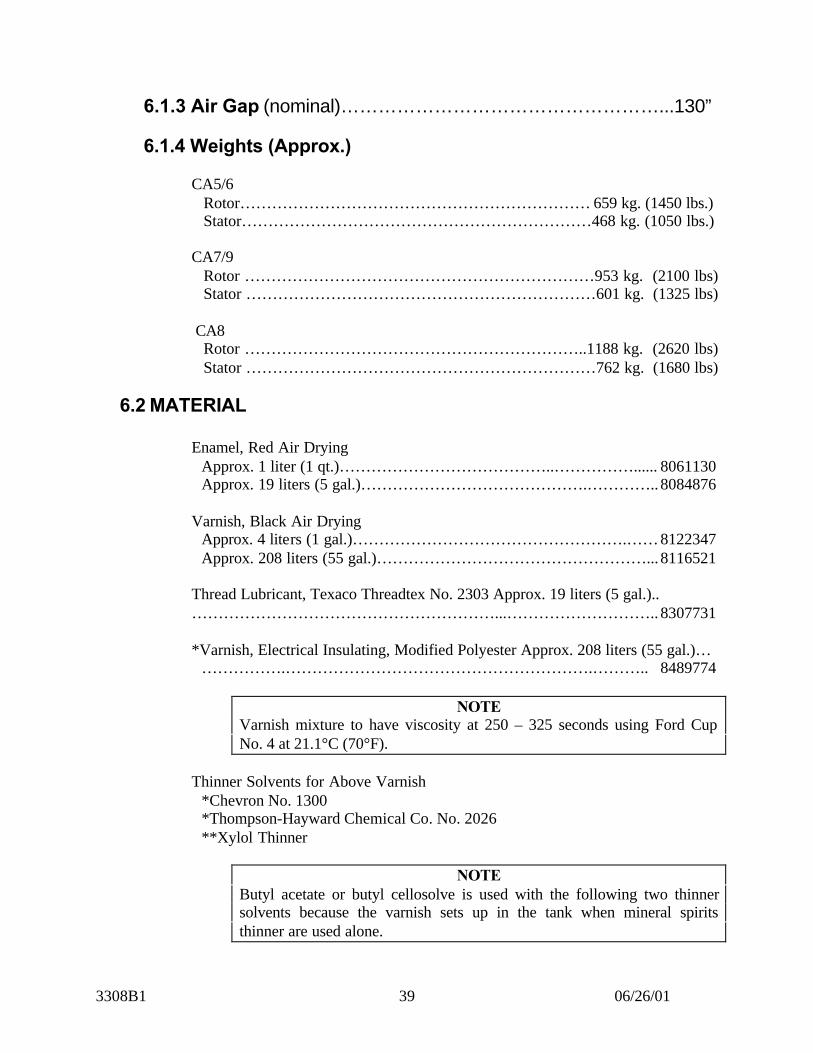
6.1.3 Air Gap (nominal)……………………………………………...130”
6.1.4 Weights (Approx.)
CA5/6Rotor………………………………………………………… 659 kg. (1450 lbs.)Stator…………………………………………………………468 kg. (1050 lbs.)
CA7/9Rotor …………………………………………………………953 kg. (2100 lbs)Stator …………………………………………………………601 kg. (1325 lbs)
CA8Rotor ………………………………………………………..1188 kg. (2620 lbs)Stator …………………………………………………………762 kg. (1680 lbs)
6.2 MATERIAL
Enamel, Red Air DryingApprox. 1 liter (1 qt.)…………………………………..……………...... 8061130Approx. 19 liters (5 gal.)…………………………………….…………..8084876
Varnish, Black Air DryingApprox. 4 liters (1 gal.)…………………………………………….……8122347Approx. 208 liters (55 gal.)……………………………………………...8116521
Thread Lubricant, Texaco Threadtex No. 2303 Approx. 19 liters (5 gal.)..…………………………………………………...………………………..8307731
*Varnish, Electrical Insulating, Modified Polyester Approx. 208 liters (55 gal.)……………….………………………………………………….……….. 8489774
NOTEVarnish mixture to have viscosity at 250 – 325 seconds using Ford CupNo. 4 at 21.1°C (70°F).
Thinner Solvents for Above Varnish*Chevron No. 1300*Thompson-Hayward Chemical Co. No. 2026**Xylol Thinner
NOTEButyl acetate or butyl cellosolve is used with the following two thinnersolvents because the varnish sets up in the tank when mineral spiritsthinner are used alone.
3308B1 06/26/0140
Alternate Thinner………………………………………………………….9083470*Mineral Spirits (Rule 66 Type Thinner) 80%*Butyl Acetate, Technical Grade 20%
Alternate Thinner………………………………………………………….9544540*Mineral Spirits (Rule 66 Type Thinner) 70%*Butyl Cellosolve 30%
6.3 TOOLSMegger, Insulation Resistance Test Set…………...………………………..8174880
Leads, 3.7 m (12 ft.)……………………………………………. ………8174878Carrying Case…………………………………………………….……...8174879
Collector Ring Grinder Assembly………………………………...………8219264Adapter-Supports Collector Ring Grinder (small 8” bearing).………...… 9506268Adapter-Supports Collector Ring Grinder (Large 10” bearing)……..……9506268Grinding Stone, Coarse……………………………………………….…...8260375Grinding Stone, Medium………………………………………………….8496921Grinding Stone, Finish…………………………………………………….8204167Alternator Rotor Support (lifting tool)……………………….………†File No. 924Brush Tension Testing (0 – 15 pound range)…………………….………..8415805
*To be used where compliance with pollution control regulations is required.**Xylol may be used as a substitute thinner, however, Xylol DOES NOT comply with pollutioncontrol regulations.
†File Number represents facility drawings that are available (at no charge) from EMD ServiceDepartment. These drawings include construction details of tooling that can be manufactured.
Document Number A11518
Electro-Motive Division of General Motors CorporationLa Grange, Illinois 60525 USATelex: 270041 McCook, Illinois USACable: ELMO DIV La Grange, Illinois USATelephone: 708-387-6000
©2001Electro-Motive Division, General Motors Corporation. All rights reserved.Neither this document, nor any part thereof, may be reprinted without theexpressed written consent of the General Motors Locomotive Group.Contact EMD Customer Publications Office.