Embed Size (px)
Citation preview
IIMMPPOORRTTAANNTT!!DDOO NNOOTT DDEESSTTRROOYY
IInnssttaallllaattiioonn,, OOppeerraattiioonn,, &&MMaaiinntteennaannccee MMaannuuaall
MMoonntthh YYeeaarr
GGoorrbbeell®® DDeeaalleerr
DDaattee
WWoorrkk SSttaattiioonn CCrraanneeTTrraaccttoorr DDrriivvee
GGoorrbbeell®® CCuussttoommeerr OOrrddeerr NNoo.. // SSeerriiaall NNoo..
®

TABLE OF CONTENTS
Introduction . . . . . . . . . . . . . . . . . . . . . . . . . . . . . . . . . . . . . . . . . . . . . . . . .1
InstallationStep 1 - Pre-Assembly . . . . . . . . . . . . . . . . . . . . . . . . . . . . . . . . . . . . . . . . . . . . . . .2
Step 2 - Verify Tractor Drive Assembly . . . . . . . . . . . . . . . . . . . . . . . . . . . . . . . . . . .2
Step 3 - End Truck/Hoist Trolley Bracket Installation . . . . . . . . . . . . . . . . . . . . . . . .3
Step 4 - Tractor Drive Installation and Leveling . . . . . . . . . . . . . . . . . . . . . . . . . . . .4
Step 5 - Drive Wheel Adjustment . . . . . . . . . . . . . . . . . . . . . . . . . . . . . . . . . . . . . . .5
Step 6 - End Truck/Hoist Trolley to Tractor Drive Connection . . . . . . . . . . . . . . . . .5
Step 7 - Tractor Drive Motor Controller(s) . . . . . . . . . . . . . . . . . . . . . . . . . . . . . . .6-7
Trouble Shooting Guide . . . . . . . . . . . . . . . . . . . . . . . . . . . . . . . . . . . . . . . .7
Hardware Torque Chart . . . . . . . . . . . . . . . . . . . . . . . . . . . . . . . . . . . . . . . .7
Crane Operator Instructions . . . . . . . . . . . . . . . . . . . . . . . . . . . . . . . . . . . .8
General Safety Requirements . . . . . . . . . . . . . . . . . . . . . . . . . . . . . . . . . . .8
Limited Warranty . . . . . . . . . . . . . . . . . . . . . . . . . . . . . . . . . . . . . . . . . . . . .9
Inspection and Maintenance Schedule . . . . . . . . . . . . . . . . . . . . . . . . . . .10
Specifications, Drawings & Literature (Inserted in this manual when applicable)Specification Sheet
General Arrangement Drawing
Electrical Schematic
Pendant Wiring Schematic
Tractor Drive Detail Drawing
Wiring Layout Drawing
Enclosure Mounting Detail
Questions? Concerns? Comments? Please call (800) 821-0086
®
INTRODUCTION
Thank you for choosing Gorbel® Work Station Crane Tractor Drives to solve your material
handling needs. The innovative design and heavy duty construction of the Gorbel® Tractor Drive
will provide a superior quality product that will offer years of long term value. Gorbel® Work
Station Crane Tractor Drives will provide many years of dependable service by following the
installation and maintenance procedures described herein.
Normal safety precautions: These include, but are not limited to:
• Checking for obstructions in crane travel
• Checking that all bolts and threaded rods are tight and have lock washers
• Making sure that end stops are in place
• Making sure that festooning cannot be snagged or pinched, whether it is electric or pneumatic
For additional safety precautions, see page 8.
WARNINGEquipment described herein is not designed for, and should not be used for, lifting, supporting, or
transporting humans. Failure to comply with any one of the limitations noted herein can result in
serious bodily injury and/or property damage. Check State and Local regulations for any
additional requirements.
WARNINGCrane cannot be utilized as a ground: A separate ground wire is required. For example,
systems with three phase power require three conductors plus one ground wire.
WARNINGReference the American Institute of Steel Construction (AISC) Manual of Steel Construction,
Specification for Structural Joints using ASTM A325 or A490 Bolts for the proper procedures to
follow when using any torque-tightening method.
111/09 ®

INSTALLATIONSTEP 1 - PRE-ASSEMBLY
Read entire installation manual before you begin installing your tractor drive.
1.1 Check packing list to make sure correct quantity of parts is included.
1.2 Tools and materials typically needed to assemble tractor drive are as follow:
• Hand tools
• Ladders/man lifts
• Torque wrench (able to torque up to 30 ft.-lb.)
STEP 2 - VERIFY THE TRACTOR DRIVE ASSEMBLY
2.1 Apply a straight edge between single wheel trolley plates
and verify the drive wheel is parallel to this straight edge
(diagram 2A). If adjustment is required, loosen the
reducer mounting screws, adjust the drive wheel alignment
and torque the reducer mounting hardware per the torque
chart on page 7.
2.2 Verify adjustment single wheel trolley is mounted to the
frame in the correct hole for your track series. Mounting
hardware should be in the lower hole for 2000 and 4000
series track as shown in diagram 2B. For 1000 series
track, the mounting hardware should be in the upper hole.
Correct if required.
TIP: Packing list can be found in plastic sleeve in hardware box: Tractor Drive General
Arrangement Drawing and additional literature can be found enclosed in this installation
manual.
�
2 11/09®
Diagram 2A. Drive Wheel Alignment.
Diagram 2B. Adjustment Single Wheel TrolleyMounting.
CAUTIONIf adjustment single wheel trolley is
mounted in wrong hole, drive wheel
could slip or bind.
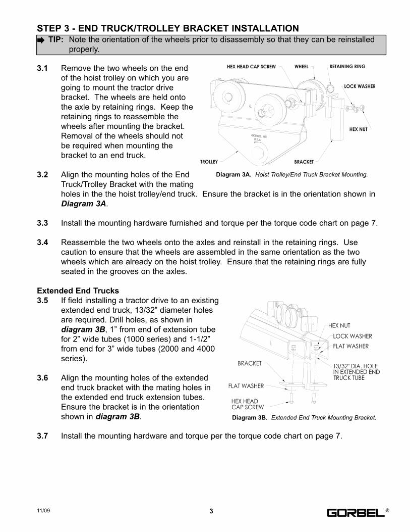
STEP 3 - END TRUCK/TROLLEY BRACKET INSTALLATION
3.1 Remove the two wheels on the end
of the hoist trolley on which you are
going to mount the tractor drive
bracket. The wheels are held onto
the axle by retaining rings. Keep the
retaining rings to reassemble the
wheels after mounting the bracket.
Removal of the wheels should not
be required when mounting the
bracket to an end truck.
3.2 Align the mounting holes of the End
Truck/Trolley Bracket with the mating
holes in the the hoist trolley/end truck. Ensure the bracket is in the orientation shown in
Diagram 3A.
3.3 Install the mounting hardware furnished and torque per the torque code chart on page 7.
3.4 Reassemble the two wheels onto the axles and reinstall in the retaining rings. Use
caution to ensure that the wheels are assembled in the same orientation as the two
wheels which are already on the hoist trolley. Ensure that the retaining rings are fully
seated in the grooves on the axles.
Extended End Trucks
3.5 If field installing a tractor drive to an existing
extended end truck, 13/32” diameter holes
are required. Drill holes, as shown in
diagram 3B, 1” from end of extension tube
for 2” wide tubes (1000 series) and 1-1/2”
from end for 3” wide tubes (2000 and 4000
series).
3.6 Align the mounting holes of the extended
end truck bracket with the mating holes in
the extended end truck extension tubes.
Ensure the bracket is in the orientation
shown in diagram 3B.
3.7 Install the mounting hardware and torque per the torque code chart on page 7.
311/09 ®
TIP: Note the orientation of the wheels prior to disassembly so that they can be reinstalled
properly.�
Diagram 3A. Hoist Trolley/End Truck Bracket Mounting.
Diagram 3B. Extended End Truck Mounting Bracket.
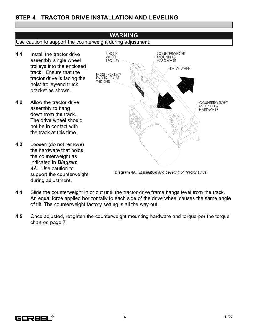
STEP 4 - TRACTOR DRIVE INSTALLATION AND LEVELING
4.1 Install the tractor drive
assembly single wheel
trolleys into the enclosed
track. Ensure that the
tractor drive is facing the
hoist trolley/end truck
bracket as shown.
4.2 Allow the tractor drive
assembly to hang
down from the track.
The drive wheel should
not be in contact with
the track at this time.
4.3 Loosen (do not remove)
the hardware that holds
the counterweight as
indicated in Diagram4A. Use caution to
support the counterweight
during adjustment.
4.4 Slide the counterweight in or out until the tractor drive frame hangs level from the track.
An equal force applied horizontally to each side of the drive wheel causes the same angle
of tilt. The counterweight factory setting is all the way out.
4.5 Once adjusted, retighten the counterweight mounting hardware and torque per the torque
chart on page 7.
4 11/09®
WARNINGUse caution to support the counterweight during adjustment.
Diagram 4A. Installation and Leveling of Tractor Drive.

STEP 5 - DRIVE WHEEL ADJUSTMENT
5.1 Prior to adjusting the drive wheel, push the tractor
drive unit along the track checking to ensure that
there are no obstructions. The drive wheel should
not yet be contacting the track.
5.2 Loosen the jam nut on the adjustment single wheel
trolley threaded rod. See Diagram 5A.
5.3 Tighten the first hex nut on the threaded rod,
against the washer and the spring, so that the drive
wheel is just starting to contact the track. The drive
wheel will contact the underside of the top surface
of the track.
5.4 Tighten the first hex nut an additional (6) turns. Additional
tightening may be required for severe applications or over
time to compensate for component wear.
5.5 Tighten the jam nut against the first hex nut locking the
first hex nut in position. Hold the hex nut in position while
tightening the jam nut to prevent the hex nut from rotating.
Note: If having trouble getting the proper adjustment, refer
to Step 2 and verify mounting position of adjustment trolley.
STEP 6 - END TRUCK/TROLLEY TO TRACTOR DRIVE CONNECTION
6.1 Carefully roll the end truck/hoist trolley up to
tractor drive unit. Use caution not to let the two
collide.
6.2 Position the hole in the hoist trolley/end truck
bracket with the hole in the tractor drive single
wheel trolley as shown in diagram 6A.
6.3 Slide the pin portion of the master link into the
holes as shown in diagram 6A. Slide the side
plate onto the master link pins and secure with
cotter pins.
Note: Part number TDM.LINK includes master link, master link side plate and cotter pins.
Diagram 6A. Link Pin Installation.
511/09 ®
TIP: The drive wheel pressure can be adjusted to compensate for wheel wear or slippage
due to severe applications.�
WARNINGUse caution to support the tractor drive prior to adjusting the drive wheel pressure.
Diagram 5A. Drive Wheel Adjustment.
Diagram 5B. Single Wheel TrolleyDifference.

STEP 7 - TRACTOR DRIVE MOTOR CONTROLLER(S)
The drive controller(s) for the Tractor Drives are pre-programmed at Gorbel for variable speed
(VFD) operation. For trouble shooting and general information, a brief summary of how the drive
controller(s) are designed to be used is included below. No additional programming is required.
VFD - ONE, TWO OR THREE SPEED OPTIONThe motor speed is varied to determine the desired tractor drive speed. The reducer ratio used
is that for the fastest speed: 120 fpm. The drive controller(s) are then programmed for the motor
to operate at one, two or three different percentages of full speed based on the desired speeds
specified by the customer at the time the order is placed.
DRIVE CONTROLLER PROGRAMMINGGorbel pre-programs a number of parameters in the drive controller prior to shipment. The
remaining parameters are left at the factory default settings. All parameters are stored on the
EPM module. These parameters are as follows:
Parameter 50 contains the fault history of the last eight (8) faults with the most recent first.
Pressing the “Mode” button three times will access this parameter (see Variable Frequency Drive
Manual).
6 11/09
Parameter # Name New Value
1 Line Voltage High or Low (see manual)
4 Stop Method Ramp to stop
5 Standard Speed Source Preset speed
10 TB-13A Function Select Run reverse
11 TB-13B Function Select Preset speed
12 TB-13C Function Select Preset speed
17 Rotation Forward and Reverse
19 Acceleration 5 seconds
20 Deceleration 3 seconds
23 Minimum Frequency 0 Hz
24 Maximum Frequency 60 Hz
26 Motor Overload As required (see manual)
31 Preset Speed 1 As required (0-60 Hz)
32 Preset Speed 2 As required (0-60 Hz)
36 Preset Speed 3 As required (0-60 Hz)
®
WARNINGThe drive controller must only operate on its own control voltage and not be connected to an
external voltage source. Allowing 24 or 120 voltage to go through the drive will PERMANENTLY
DAMAGE the internal controls!
Note: The VFD consists of pre-set speeds, it is not infinitely variable during use.
STEP 7 - TRACTOR DRIVE MOTOR CONTROLLER(S) (CONTINUED)
Deceleration time: The deceleration time is factory set at 3 seconds. This can be adjusted to a
shorter time period with the following warning. If the deceleration time is set to too short a time
period, the drive controller will shut down and show an alarm. This is the result of the bridge or
trolley having too much inertia for the reducer and motor to stop in such a short time. If this
occurs, increase the deceleration time.
TROUBLE SHOOTING GUIDE
If you are experiencing any other problems in the start-up or operation of your Gorbel® crane
please call (800) 821-0086.
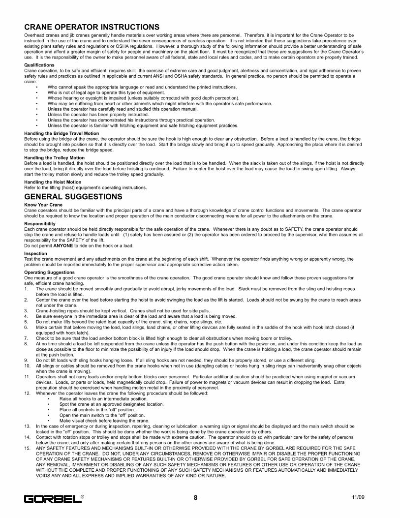
HARDWARE TORQUE CHART
711/09
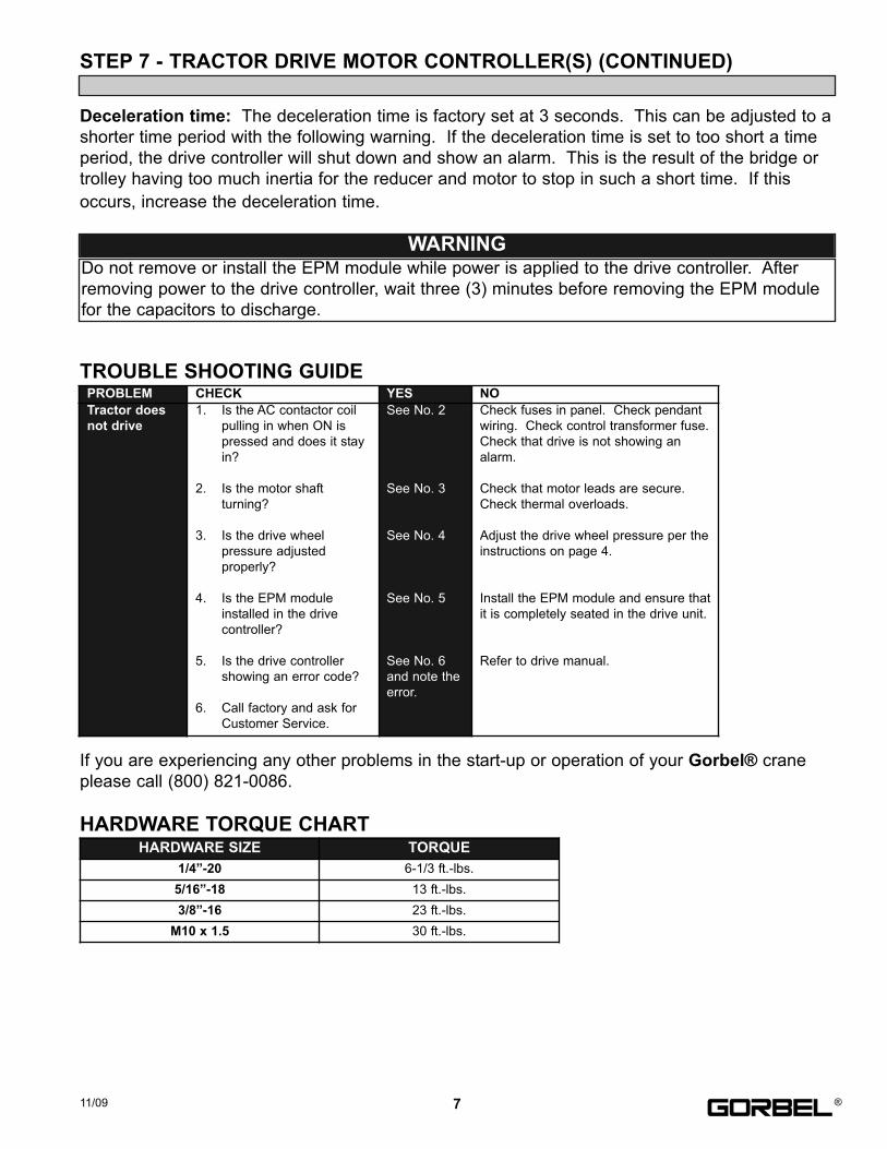
PROBLEM CHECK YES NO
Tractor does
not drive
1. Is the AC contactor coil
pulling in when ON is
pressed and does it stay
in?
2. Is the motor shaft
turning?
3. Is the drive wheel
pressure adjusted
properly?
4. Is the EPM module
installed in the drive
controller?
5. Is the drive controller
showing an error code?
6. Call factory and ask for
Customer Service.
See No. 2
See No. 3
See No. 4
See No. 5
See No. 6
and note the
error.
Check fuses in panel. Check pendant
wiring. Check control transformer fuse.
Check that drive is not showing an
alarm.
Check that motor leads are secure.
Check thermal overloads.
Adjust the drive wheel pressure per the
instructions on page 4.
Install the EPM module and ensure that
it is completely seated in the drive unit.
Refer to drive manual.
HARDWARE SIZE TORQUE
1/4”-20 6-1/3 ft.-lbs.
5/16”-18 13 ft.-lbs.
3/8”-16 23 ft.-lbs.
M10 x 1.5 30 ft.-lbs.
®
WARNINGDo not remove or install the EPM module while power is applied to the drive controller. After
removing power to the drive controller, wait three (3) minutes before removing the EPM module
for the capacitors to discharge.
CRANE OPERATOR INSTRUCTIONSOverhead cranes and jib cranes generally handle materials over working areas where there are personnel. Therefore, it is important for the Crane Operator to be
instructed in the use of the crane and to understand the sever consequences of careless operation. It is not intended that these suggestions take precedence over
existing plant safety rules and regulations or OSHA regulations. However, a thorough study of the following information should provide a better understanding of safe
operation and afford a greater margin of safety for people and machinery on the plant floor. It must be recognized that these are suggestions for the Crane Operator’s
use. It is the responsibility of the owner to make personnel aware of all federal, state and local rules and codes, and to make certain operators are properly trained.
Qualifications
Crane operation, to be safe and efficient, requires skill: the exercise of extreme care and good judgment, alertness and concentration, and rigid adherence to proven
safety rules and practices as outlined in applicable and current ANSI and OSHA safety standards. In general practice, no person should be permitted to operate a
crane:
• Who cannot speak the appropriate language or read and understand the printed instructions.
• Who is not of legal age to operate this type of equipment.
• Whose hearing or eyesight is impaired (unless suitably corrected with good depth perception).
• Who may be suffering from heart or other ailments which might interfere with the operator’s safe performance.
• Unless the operator has carefully read and studied this operation manual.
• Unless the operator has been properly instructed.
• Unless the operator has demonstrated his instructions through practical operation.
• Unless the operator is familiar with hitching equipment and safe hitching equipment practices.
Handling the Bridge Travel Motion
Before using the bridge of the crane, the operator should be sure the hook is high enough to clear any obstruction. Before a load is handled by the crane, the bridge
should be brought into position so that it is directly over the load. Start the bridge slowly and bring it up to speed gradually. Approaching the place where it is desired
to stop the bridge, reduce the bridge speed.
Handling the Trolley Motion
Before a load is handled, the hoist should be positioned directly over the load that is to be handled. When the slack is taken out of the slings, if the hoist is not directly
over the load, bring it directly over the load before hoisting is continued. Failure to center the hoist over the load may cause the load to swing upon lifting. Always
start the trolley motion slowly and reduce the trolley speed gradually.
Handling the Hoist Motion
Refer to the lifting (hoist) equipment’s operating instructions.
GENERAL SUGGESTIONSKnow Your Crane
Crane operators should be familiar with the principal parts of a crane and have a thorough knowledge of crane control functions and movements. The crane operator
should be required to know the location and proper operation of the main conductor disconnecting means for all power to the attachments on the crane.
Responsibility
Each crane operator should be held directly responsible for the safe operation of the crane. Whenever there is any doubt as to SAFETY, the crane operator should
stop the crane and refuse to handle loads until: (1) safety has been assured or (2) the operator has been ordered to proceed by the supervisor, who then assumes all
responsibility for the SAFETY of the lift.
Do not permit ANYONE to ride on the hook or a load.
Inspection
Test the crane movement and any attachments on the crane at the beginning of each shift. Whenever the operator finds anything wrong or apparently wrong, the
problem should be reported immediately to the proper supervisor and appropriate corrective action taken.
Operating Suggestions
One measure of a good crane operator is the smoothness of the crane operation. The good crane operator should know and follow these proven suggestions for
safe, efficient crane handling.
1. The crane should be moved smoothly and gradually to avoid abrupt, jerky movements of the load. Slack must be removed from the sling and hoisting ropes
before the load is lifted.
2. Center the crane over the load before starting the hoist to avoid swinging the load as the lift is started. Loads should not be swung by the crane to reach areas
not under the crane.
3. Crane-hoisting ropes should be kept vertical. Cranes shall not be used for side pulls.
4. Be sure everyone in the immediate area is clear of the load and aware that a load is being moved.
5. Do not make lifts beyond the rated load capacity of the crane, sling chains, rope slings, etc.
6. Make certain that before moving the load, load slings, load chains, or other lifting devices are fully seated in the saddle of the hook with hook latch closed (if
equipped with hook latch).
7. Check to be sure that the load and/or bottom block is lifted high enough to clear all obstructions when moving boom or trolley.
8. At no time should a load be left suspended from the crane unless the operator has the push button with the power on, and under this condition keep the load as
close as possible to the floor to minimize the possibility of an injury if the load should drop. When the crane is holding a load, the crane operator should remain
at the push button.
9. Do not lift loads with sling hooks hanging loose. If all sling hooks are not needed, they should be properly stored, or use a different sling.
10. All slings or cables should be removed from the crane hooks when not in use (dangling cables or hooks hung in sling rings can inadvertently snag other objects
when the crane is moving).
11. Operators shall not carry loads and/or empty bottom blocks over personnel. Particular additional caution should be practiced when using magnet or vacuum
devices. Loads, or parts or loads, held magnetically could drop. Failure of power to magnets or vacuum devices can result in dropping the load. Extra
precaution should be exercised when handling molten metal in the proximity of personnel.
12. Whenever the operator leaves the crane the following procedure should be followed:
• Raise all hooks to an intermediate position.
• Spot the crane at an approved designated location.
• Place all controls in the “off” position.
• Open the main switch to the “off” position.
• Make visual check before leaving the crane.
13. In the case of emergency or during inspection, repairing, cleaning or lubrication, a warning sign or signal should be displayed and the main switch should be
locked in the “off” position. This should be done whether the work is being done by the crane operator or by others.
14. Contact with rotation stops or trolley end stops shall be made with extreme caution. The operator should do so with particular care for the safety of persons
below the crane, and only after making certain that any persons on the other cranes are aware of what is being done.
15. ANY SAFETY FEATURES AND MECHANISMS BUILT-IN OR OTHERWISE PROVIDED WITH THE CRANE BY GORBEL ARE REQUIRED FOR THE SAFE
OPERATION OF THE CRANE. DO NOT, UNDER ANY CIRCUMSTANCES, REMOVE OR OTHERWISE IMPAIR OR DISABLE THE PROPER FUNCTIONING
OF ANY CRANE SAFETY MECHANISMS OR FEATURES BUILT-IN OR OTHERWISE PROVIDED BY GORBEL FOR SAFE OPERATION OF THE CRANE.
ANY REMOVAL, IMPAIRMENT OR DISABLING OF ANY SUCH SAFETY MECHANISMS OR FEATURES OR OTHER USE OR OPERATION OF THE CRANE
WITHOUT THE COMPLETE AND PROPER FUNCTIONING OF ANY SUCH SAFETY MECHANISMS OR FEATURES AUTOMATICALLY AND IMMEDIATELY
VOIDS ANY AND ALL EXPRESS AND IMPLIED WARRANTIES OF ANY KIND OR NATURE.
8 11/09®
LIMITED WARRANTYIt is agreed that the equipment purchased hereunder is subject to the following LIMITED warranty and no other. Gorbel Incorporated ("Gorbel"), warrants the manual
push-pull Work Station Cranes, Jib Crane, and Gantry Crane products to be free from defects in material or workmanship for a period of five years or 10,000 hours
use from date of shipment. Gorbel warrants the Motorized Work Station Cranes and Jib Crane products to be free from defects in material or workmanship for a
period of two years or 4,000 hours use from the date of shipment. Gorbel warrants the G-Force® and Easy Arm™ products to be free from defects in material or
workmanship for a period of one year or 2,000 hours use from the date of shipment. This warranty shall not cover failure or defective operation caused by operation
in excess of recommended capacities, misuses, negligence or accident, and alteration or repair not authorized by Gorbel. No system shall be modified after
manufacture without the written authorization of Gorbel, Inc. Any field modification made to the system without the written authorization of Gorbel, Inc. shall void
Gorbel’s warranty obligation. OTHER THAN AS SET FORTH HEREIN, NO OTHER EXPRESS WARRANTIES, AND NO IMPLIED WARRANTIES, ORAL OR
WRITTEN, INCLUDING BUT NOT LIMITED TO THE WARRANTIES OF MERCHANTABILITY OR FITNESS FOR A PARTICULAR PURPOSE, ARE MADE BY
GORBEL WITH RESPECT TO ITS PRODUCTS AND ALL SUCH WARRANTIES ARE HEREBY SPECIFICALLY DISCLAIMED. GORBEL SHALL NOT BE LIABLE
UNDER ANY CIRCUMSTANCES FOR ANY INCIDENTAL, SPECIAL AND/OR CONSEQUENTIAL DAMAGES WHATSOEVER, WHETHER OR NOT FORESEEABLE,
INCLUDING BUT NOT LIMITED TO DAMAGES FOR LOST PROFITS AND ALL SUCH INCIDENTAL, SPECIAL AND/OR CONSEQUENTIAL DAMAGES ARE
HEREBY ALSO SPECIFICALLY DISCLAIMED. Gorbel's obligation and Purchaser's or end user's sole remedy under this warranty is limited to the replacement or
repair of Gorbel's products at the factory, or at the discretion of Gorbel, at a location designated by Gorbel. Purchaser or end user shall be solely responsible for all
freight and transportation costs incurred in connection with any warranty work provided by Gorbel hereunder. Gorbel will not be liable for any loss, injury or damage to
persons or property, nor for damages of any kind resulting from failure or defective operation of any materials or equipment furnished hereunder. Components and
accessories not manufactured by Gorbel are not included in this warranty. Purchaser's or end user's remedy for components and accessories not manufactured by
Gorbel is limited to and determined by the terms and conditions of the warranty provided by the respective manufacturers of such components and accessories.
A) DISCLAIMER OF IMPLIED WARRANTY OF MERCHANTABILITY
Gorbel and Purchaser agree that the implied warranty of merchantability is excluded from this transaction and shall not apply to the goods
involved in this transaction.
B) DISCLAIMER OF IMPLIED WARRANTY OF FITNESS FOR PARTICULAR PURPOSE
Gorbel and Purchaser agree that the implied warranty of fitness for particular purpose is excluded from this transaction and shall not apply to
the goods involved in this transaction.
C) DISCLAIMER OF EXPRESS WARRANTY
Gorbel's agents, or dealer's agents, or distributor's agents may have made oral statements about the machinery and equipment described in
this transaction. Such statements do not constitute warranties, and Purchaser agrees not to rely on such statements. Purchaser also agrees
that such statements are not part of this transaction.
D) DISCLAIMER OF SPECIAL, INCIDENTAL AND CONSEQUENTIAL DAMAGES
Gorbel and Purchaser agree that any claim made by Purchaser which is inconsistent with Gorbel's obligations and the warranty remedies
provided with Gorbel's products, and in particular, special, incidental and consequential damages, are expressly excluded.
E) DEALER OR DISTRIBUTOR NOT AN AGENT
Gorbel and Purchaser agree that Purchaser has been put on notice that dealer or distributor is not Gorbel's agent in any respect for any
reason. Gorbel and Purchaser also agree that Purchaser has been put on notice that dealer or distributor is not authorized to incur any
obligations or to make any representations or warranties on Gorbel's behalf other than those specifically set forth in Gorbel's warranty provided
in connection with its product.
F) MERGER
This warranty agreement constitutes a final and complete written expression of all the terms and conditions of this warranty and is a complete
and exclusive statement of those terms.
G) PAINTING
Every crane (excluding components) receives a quality paint job before leaving the factory. Unfortunately, no paint will protect against the
abuses received during the transportation process via common carrier. We have included at least one (1) twelve ounce spray can for touchup
with each crane ordered (unless special paint was specified). If additional paint is required, contact a Gorbel® Customer Service
Representative at 1-800-821-0086 or 1-585-924-6262.
Title and Ownership:
Title to the machinery and equipment described in the foregoing proposal shall remain with the Gorbel and shall not pass to the Purchaser until the full amount
herein agreed to be paid has been fully paid in cash.
Claims and Damages:
Unless expressly stated in writing, goods and equipment shall be at Purchaser's risk on and after Seller's delivery in good shipping order to the Carrier. Gorbel
shall in no event be held responsible for materials furnished or work performed by any person other than it or its authorized representative or agent.
Cancellations:
If it becomes necessary for the purchaser to cancel this order wholly or in part, he shall at once so advise Gorbel in writing. Upon receipt of such written notice
all work will stop immediately. If the order entails only stock items, a flat restocking charge of 15% of the purchase price will become due and payable by
Purchaser to Gorbel. Items purchased specifically for the canceled order shall be charged for in accordance with the cancellation charges of our supplier plus
15% for handling in our factory. The cost of material and/or labor expended in general fabrication for the order shall be charged for on the basis of total costs to
Gorbel up to the time of cancellation plus 15%.
Returns:
No equipment, materials or parts may be returned to Gorbel without express permission in writing to do so.
Extra Charge Delay: If Purchaser delays or interrupts progress of Seller's performance, or causes changes to be made, Purchaser agrees to reimburse Gorbel
for expense, if any, incident to such delay.
Changes and Alterations:
Gorbel reserves the right to make changes in the details of construction of the equipment, as in its judgment, will be in the interest of the Purchaser; will make
any changes in or additions to the equipment which may be agreed upon in writing by the Purchaser; and Gorbel is not obligated to make such changes in
products previously sold any customer.
Third Party Action:
Should Gorbel have to resort to third party action to collect any amount due after there (30) days from date of invoice, the Purchaser agrees to pay collection
costs, reasonable attorney's fees, court costs and legal interest.
OSHA Responsibilities:
Gorbel agrees to fully cooperate with Purchaser in the design, manufacture or procurement of safety features or devices that comply with OSHA regulations. In
the event additional equipment or labor shall be furnished by Gorbel, it will be at prices and standard rates then in effect, or as may be mutually agreed upon at
the time of the additional installation.
Equal Employment Opportunity:
Gorbel agrees to take affirmative action to ensure equal employment opportunity for all job applicants and employees without regard to race, color, age, religion,
sex, national origin, handicap, veteran, or marital status. Gorbel agrees to maintain non-segregated work facilities and comply to rules and regulations of the
Secretary of Labor or as otherwise provided by law or Executive Order.
911/09 ®
INSPECTION AND MAINTENANCE SCHEDULE
* Federal, state and local codes may require inspection and maintenance checks ore often.
Please check the federal, state and local code manuals in your area.
WARNINGAny changes in operation or unusual noises must be immediately identified and corrected.
600 Fishers Run, P.O. Box 593
Fishers, NY 14453-0593
Telephone: (800) 821-0086
Fax: (800) 828-1808
E-mail: [email protected]
http://www.gorbel.com
© 2009 Gorbel, Inc.
All Rights Reserved
10 11/09
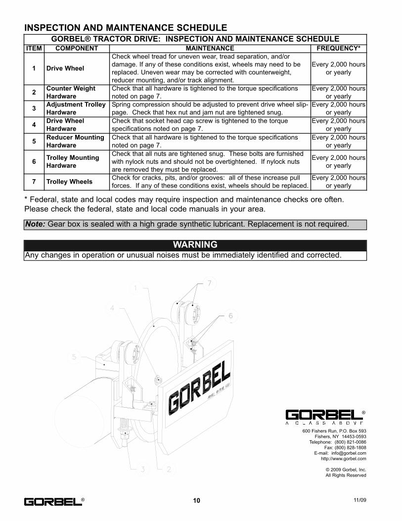
GORBEL® TRACTOR DRIVE: INSPECTION AND MAINTENANCE SCHEDULEITEM COMPONENT MAINTENANCE FREQUENCY*
1 Drive Wheel
Check wheel tread for uneven wear, tread separation, and/or
damage. If any of these conditions exist, wheels may need to be
replaced. Uneven wear may be corrected with counterweight,
reducer mounting, and/or track alignment.
Every 2,000 hours
or yearly
2Counter Weight
Hardware
Check that all hardware is tightened to the torque specifications
noted on page 7.
Every 2,000 hours
or yearly
3Adjustment Trolley
Hardware
Spring compression should be adjusted to prevent drive wheel slip-
page. Check that hex nut and jam nut are tightened snug.
Every 2,000 hours
or yearly
4Drive Wheel
Hardware
Check that socket head cap screw is tightened to the torque
specifications noted on page 7.
Every 2,000 hours
or yearly
5Reducer Mounting
Hardware
Check that all hardware is tightened to the torque specifications
noted on page 7.
Every 2,000 hours
or yearly
6Trolley Mounting
Hardware
Check that all nuts are tightened snug. These bolts are furnished
with nylock nuts and should not be overtightened. If nylock nuts
are removed they must be replaced.
Every 2,000 hours
or yearly
7 Trolley WheelsCheck for cracks, pits, and/or grooves: all of these increase pull
forces. If any of these conditions exist, wheels should be replaced.
Every 2,000 hours
or yearly
®
®
Note: Gear box is sealed with a high grade synthetic lubricant. Replacement is not required.