Embed Size (px)
Citation preview

Trade of Metal Fabrication Module 2: Thermal Processes
Unit 7: Introduction to Plasma Arc Cutting
Phase 2

Trade of Metal Fabrication – Phase 2 Module 2 Unit 7
Unit 7 3
Table of Contents
List of Figures .................................................................................................................... 4
List of Tables ..................................................................................................................... 5
Document Release History ............................................................................................... 6
Module 2 – Thermal Processes ........................................................................................ 7
Unit 7 – Introduction to Plasma Arc Cutting .................................................................. 7 Learning Outcome: ..................................................................................................... 7 Key Learning Points: .................................................................................................. 7 Training Resources: .................................................................................................... 7 Key Learning Points Code: ......................................................................................... 7
Plasma Arc Cutting........................................................................................................... 8
Plasma Arc Welding and Cutting .................................................................................... 9
Safety .............................................................................................................................. 9 Welding ......................................................................................................................... 10
Theory and Principles ............................................................................................... 10 Advantages and Applications ................................................................................... 11
Cutting .......................................................................................................................... 11 Theory and Principles ............................................................................................... 11 Cutting Gases ............................................................................................................ 12 Cutting Speed ............................................................................................................ 12
Self Assessment................................................................................................................ 13
Answers to Questions 1-2. Module 2. Unit 7 ................................................................. 14
Index ................................................................................................................................. 16

Trade of Metal Fabrication – Phase 2 Module 2 Unit 7
Unit 7 4
List of Figures
Figure 1 - Plasma Arc Cutting ............................................................................................ 8
Figure 2 - Plasma-Arc Nozzle Set-Up ................................................................................ 9
Figure 3 - Keyhole Method of Welding ............................................................................ 10

Trade of Metal Fabrication – Phase 2 Module 2 Unit 7
Unit 7 5
List of Tables
Table 1 - Materials Welded using Plasma-Arc Welding .................................................. 11
Table 2 - Variation of Cutting Speed with Typical Gas-type and Current ....................... 12

Trade of Metal Fabrication – Phase 2 Module 2 Unit 7
Unit 7 6
Document Release History
Date Version Comments
01/11/06 First draft
13/12/13 SOLAS transfer
Trade of Metal Fabrication – Phase 2 Module 2 Unit 7
Unit 7 7
Module 2 – Thermal Processes
Unit 7 – Introduction to Plasma Arc Cutting
Duration – 4 Hours
Learning Outcome:
By the end of this unit each apprentice will be able to:
List the applications, characteristics and hazards associated with plasma cutting
Safely set up the equipment, adjust air pressure and current to correct settings for exercise
State the safety precautions to be observed – safe working area/PPE
Cut mild steel/stainless, aluminium sheet freehand and with the use of cutting attachments (straight and circular guides)
Key Learning Points:
Sk Rk Assembly of equipment.
Rk M Regulation of air pressure.
Sk Rk Regulation of current.
Sk Rk Maintenance and care of plant.
Sk Rk Sc Plasma arc principles, techniques and applications.
Rk Sc Applications and characteristics of the plasma arc process.
Rk Identification of various attachments for straight and circular cuts.
Sk Cutting techniques.
M Rk Calculations for straight, circular and irregular cuts – kerf width/cutting speeds.
P Effective communication/questions – tidy work area.
Training Resources:
Plasma arc cutting plant and range of attachments – safety clothing and personal protective equipment. Fabrication workshop facilities.
Key Learning Points Code:
M = Maths D= Drawing RK = Related Knowledge Sc = Science
P = Personal Skills Sk = Skill H = Hazards
Trade of Metal Fabrication – Phase 2 Module 2 Unit 7
Unit 7 8
Plasma Arc Cutting
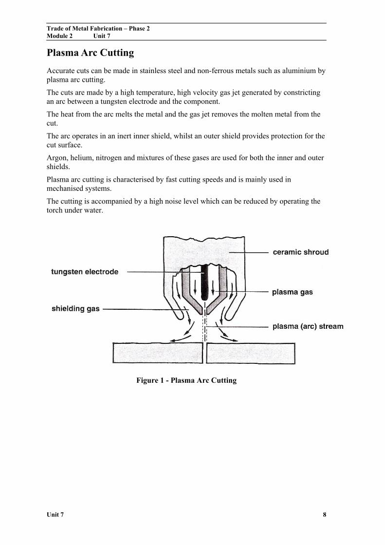
Accurate cuts can be made in stainless steel and non-ferrous metals such as aluminium by plasma arc cutting.
The cuts are made by a high temperature, high velocity gas jet generated by constricting an arc between a tungsten electrode and the component.
The heat from the arc melts the metal and the gas jet removes the molten metal from the cut.
The arc operates in an inert inner shield, whilst an outer shield provides protection for the cut surface.
Argon, helium, nitrogen and mixtures of these gases are used for both the inner and outer shields.
Plasma arc cutting is characterised by fast cutting speeds and is mainly used in mechanised systems.
The cutting is accompanied by a high noise level which can be reduced by operating the torch under water.
Figure 1 - Plasma Arc Cutting
Trade of Metal Fabrication – Phase 2 Module 2 Unit 7
Unit 7 9
Plasma Arc Welding and Cutting
Safety
As for other arc processes plus the following: Danger of severe electric shock from the high open circuit voltage, up to 400 V for cutting. Dangerous fumes and noxious gases when using nitrogen mixtures so it is important to have adequate fume extraction. The intense arc requires a darker shade of filter glass, at least 16 EW (BS 697). Intense high-frequency noise is possible when cutting, especially with non-transferred arcs, of levels 110 dB which requires ear muff protection.
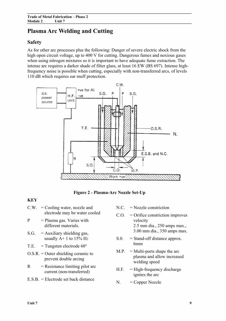
Figure 2 - Plasma-Arc Nozzle Set-Up
KEY
C.W. = Cooling water, nozzle and electrode may be water cooled
P = Plasma gas. Varies with different materials.
S.G. = Auxiliary shielding gas, usually A+ 1 to 15% H2
T.E. = Tungsten electrode 60°
O.S.R. = Outer shielding ceramic to prevent double arcing
R = Resistance limiting pilot arc current (non-transferred)
E.S.B. = Electrode set back distance
N.C. = Nozzle constriction
C.O. = Orifice constriction improves velocity 2.5 mm dia., 250 amps max., 3.00 mm dia., 350 amps max.
S.0. = Stand-off distance approx. 6mm
M.P. = Multi-ports shape the arc plasma and allow increased welding speed
H.F. = High-frequency discharge ignites the arc
N. = Copper Nozzle
Trade of Metal Fabrication – Phase 2 Module 2 Unit 7
Unit 7 10
Welding
Theory and Principles
The specially designed copper nozzle has a constricted orifice with a tungsten electrode set back in the body (Figure 2). When an arc is struck, the plasma-forming gas, e.g. argon/hydrogen mixture, is ionised and becomes electrically conductive. This high-temperature ionised gas stream attains a high velocity (near the speed of sound) mainly due to the arc being constricted, and rapidly melts the parent metal. Figure 2 shows the transferred arc method where the arc is established between the tungsten and the work.
Another method, used for welding materials which are not electrically conductive, is the non-transferred arc method where the arc is established between the tungsten and the copper nozzle. High open circuit voltages (110-120 OCV) and high-frequency units assist arc starting, or a pilot arc from electrode to nozzle.
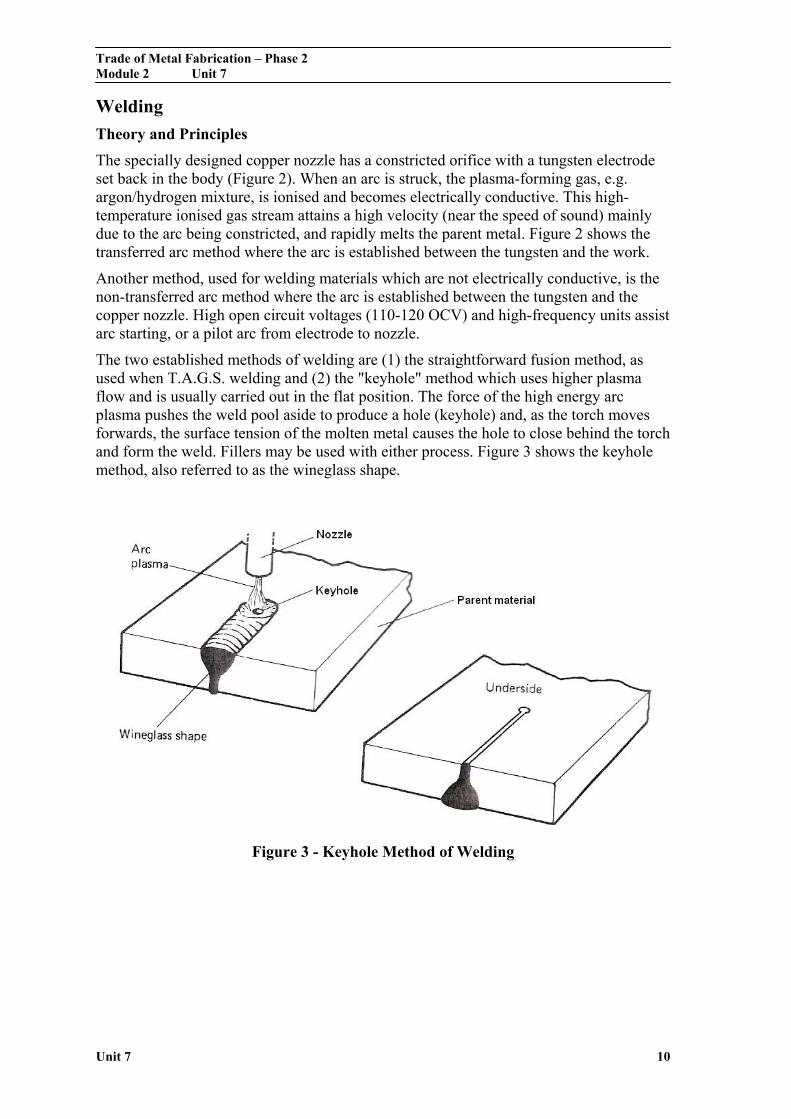
The two established methods of welding are (1) the straightforward fusion method, as used when T.A.G.S. welding and (2) the "keyhole" method which uses higher plasma flow and is usually carried out in the flat position. The force of the high energy arc plasma pushes the weld pool aside to produce a hole (keyhole) and, as the torch moves forwards, the surface tension of the molten metal causes the hole to close behind the torch and form the weld. Fillers may be used with either process. Figure 3 shows the keyhole method, also referred to as the wineglass shape.
Figure 3 - Keyhole Method of Welding
Trade of Metal Fabrication – Phase 2 Module 2 Unit 7
Unit 7 11
Advantages and Applications
1. Most materials may be welded, metal and some non-metals with and without filler.
2. Good penetration control with little distortion, especially on straight butt welds within the range 3-12 mm thick.
3. Good weld appearance.
4. Chemical and aero-engine components. Circumferential pipe welds, etc.
5. High welding speeds up to 10 mm thick with little joint preparation or filler.
6. Narrow H.A.Z. and fewer passes than with T.A.G.S. welding, with faster welding speeds.
7. Micro plasma for thin sheet.
Cutting
Theory and Principles
The transferred plasma arc is used for cutting metals because of the very high energy density and velocity of the plasma jet.
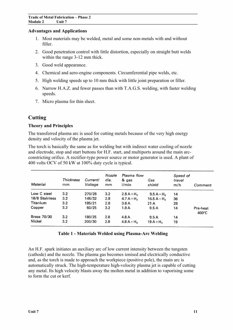
The torch is basically the same as for welding but with indirect water cooling of nozzle and electrode, stop and start buttons for H.F. start, and multiports around the main arc-constricting orifice. A rectifier-type power source or motor generator is used. A plant of 400 volts OCV of 50 kW at 100% duty cycle is typical.
Table 1 - Materials Welded using Plasma-Arc Welding
An H.F. spark initiates an auxiliary arc of low current intensity between the tungsten (cathode) and the nozzle. The plasma gas becomes ionised and electrically conductive and, as the torch is made to approach the workpiece (positive pole), the main arc is automatically struck. The high-temperature high-velocity plasma jet is capable of cutting any metal. Its high velocity blasts away the molten metal in addition to vaporising some to form the cut or kerf.
Trade of Metal Fabrication – Phase 2 Module 2 Unit 7
Unit 7 12
Cutting Gases
Aluminium and stainless steels require non-oxidising gases for good cutting results in both thin and thick sections. Argon/hydrogen mixtures permit good cuts and high cutting rates because the hydrogen increases the arc voltage and thermal conductivity of the mixture. Parallel kerfs, little dross, oxide-free cut faces and minimal fumes result from the use of A/H2 mixtures. Argon/Hydrogen/Nitrogen or A/N2 mixtures are used when machine cutting, but nitrogen is not recommended for hand cutting due to the formation of poisonous oxides of nitrogen. Higher cutting speeds are possible with this cheaper mixture with little loss of quality. The increase in cutting efficiency is probably derived from the greater anodic voltage drop associated with the nitrogen gas.
When inert gases such as argon are used, the heat is derived from the electrical energy of the arc. Carbon steels require an oxidising gas for the best results; the exothermic iron-oxygen reaction provides additional heat at the cutting point and so reduces the amount of electric power required. Air has proved to be a most efficient gas.
Cutting Speed
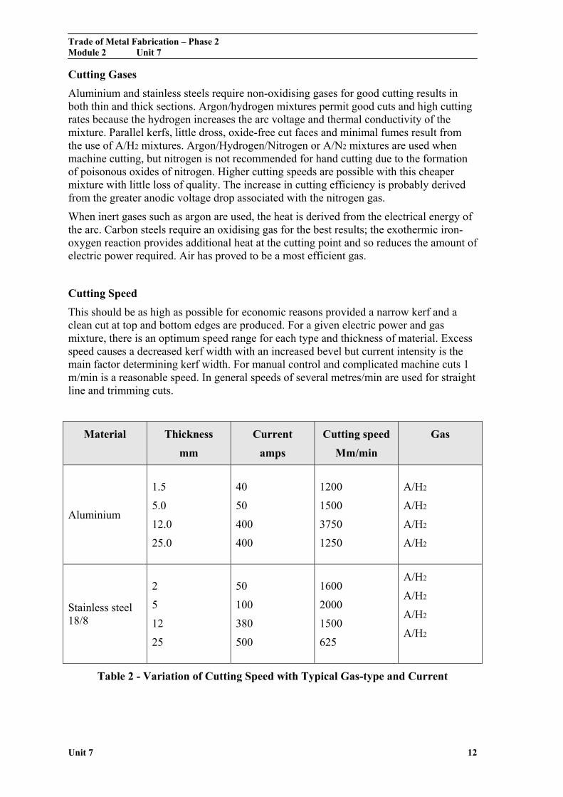
This should be as high as possible for economic reasons provided a narrow kerf and a clean cut at top and bottom edges are produced. For a given electric power and gas mixture, there is an optimum speed range for each type and thickness of material. Excess speed causes a decreased kerf width with an increased bevel but current intensity is the main factor determining kerf width. For manual control and complicated machine cuts 1 m/min is a reasonable speed. In general speeds of several metres/min are used for straight line and trimming cuts.
Material Thickness
mm
Current
amps
Cutting speed
Mm/min
Gas
Aluminium
1.5
5.0
12.0
25.0
40
50
400
400
1200
1500
3750
1250
A/H2
A/H2
A/H2
A/H2
Stainless steel 18/8
2
5
12
25
50
100
380
500
1600
2000
1500
625
A/H2
A/H2
A/H2
A/H2
Table 2 - Variation of Cutting Speed with Typical Gas-type and Current
Trade of Metal Fabrication – Phase 2 Module 2 Unit 7
Unit 7 13
Self Assessment
Questions on Background Notes – Module 2.Unit 7
1. Briefly explain the Plasma Cutting Process.
2. List some Safety Precautions when using the Plasma Machine.
Trade of Metal Fabrication – Phase 2 Module 2 Unit 7
Unit 7 14
Answers to Questions 1-2. Module 2. Unit 7
1.
Plasma Arc Cutting:
Accurate cuts can be made in stainless steel and non-ferrous
metals such as aluminium by plasma arc cutting.
The cuts are made by a high temperature, high velocity gas jet
generated by constricting an arc between a tungsten electrode
and the component.
The heat from the arc melts the metal and the gas jet removes
the molten metal from the cut.
The arc operates in an inert inner shield, whilst an outer shield
provides protection for the cutting surface.
Argon, helium, nitrogen and mixtures of these gases are used
for both the inner and outer shields.
Plasma arc cutting is characterised by fast cutting speeds and is
mainly used in mechanised systems.
The cutting is accompanied by a high noise level which can be
reduced by operating the torch under water.
Trade of Metal Fabrication – Phase 2 Module 2 Unit 7
Unit 7 15
2.
Safety Precautions: When using the Plasma Machine
Danger of severe electric shock from the high open circuit voltage
up to 400 V for cutting.
Dangerous fumes and noxious gases when using nitrogen mixtures
so it is important to have adequate fume extraction.
The intense arc requires a darker shade of filter glass, at least
16EW (BS 697)
Intense high-frequency noise is possible when cutting, especially
with non-transferred arcs. Levels of 110dB require ear muffs.

Trade of Metal Fabrication – Phase 2 Module 2 Unit 7
Unit 7 16
Index
C Cutting
Cutting Gases, 12 Cutting Speed, 12 Theory and Principles, 11
P Plasma Arc Cutting, 8 Plasma Arc Welding and Cutting, 9
Cutting, 11 Safety, 9 Welding, 10
W Welding
Advantages and Applications, 11 Theory and Principles, 10