Embed Size (px)
Citation preview
Page 1 of 1
© 2004 by NETGEAR, Inc. All rights reserved.
Trademarks
@2004 NETGEAR, Inc. NETGEAR, the Netgear logo, The Gear Guy and Everybody’s connecting are trademarks of Netgear, Inc. in the United States and/or other countries. Other brand and product names are trademarks of their respective holders. Information is subject to change without notice. All rights reserved.
Statement of Conditions
In the interest of improving internal design, operational function, and/or reliability, NETGEAR reserves the right to make changes to the products described in this document without notice. NETGEAR does not assume any liability that may occur due to the use or application of the product(s) or circuit layout(s) described herein.
Page 2 of 2
CONTENTS
Trademarks .....................................................................................................................................................................................1 Statement of Conditions....................................................................................................................................................................1
CHAPTER 1: SWITCH MANAGEMENT OVERVIEW ................................................................................................................................3
MANAGEMENT ACCESS OVERVIEW........................................................................................................................................... 3
CHAPTER 2: GETTING STARTED...........................................................................................................................................................4
NETWORK WITH DHCP SERVER: .............................................................................................................................................. 4 Smartwizard Discovery Utility > Discover...........................................................................................................................................4 Smartwizard Discovery > Web Access................................................................................................................................................5 Web Management ............................................................................................................................................................................5
NETWORK WITHOUT DHCP SERVER .......................................................................................................................................... 6 Smartwizard Discovery > Configuration Setting > Assign Static IP.......................................................................................................6 Web Management ............................................................................................................................................................................7
CHAPTER 3: WEB MANAGEMENT ACCESS ..........................................................................................................................................8
SYSTEM> SWITCH STATUS PAGE............................................................................................................................................. 9 SYSTEM> IP ACCESS LIST PAGE............................................................................................................................................. 9 SYSTEM> SET-UP PAGE...................................................................................................................................................... 10 SYSTEM> PASSWORD PAGE ................................................................................................................................................. 10 SWITCH MENU.................................................................................................................................................................. 10 SWITCH> PORT CONFIGURATION PAGE.................................................................................................................................... 10
Switch> Port Configuration: Set speed.............................................................................................................................................11 Switch> Port Configuration: Set flow control....................................................................................................................................11 Switch> Port Configuration: Set QOS ..............................................................................................................................................11
SWITCH> STATISTICS PAGE ................................................................................................................................................. 12 Switch> Statistics> Refresh...........................................................................................................................................................12 Switch> Statistics> Clear Counter ..................................................................................................................................................12
SWITCH> VLAN PAGE ....................................................................................................................................................... 12 Switch> VLAN> Port-based VLAN ................................................................................................................................................13 Switch> VLAN> IEEE802.1Q Tag VLAN .......................................................................................................................................13
SWITCH> TRUNKING PAGE .................................................................................................................................................. 15 FIRMWARE MENU ............................................................................................................................................................. 15 FIRMWARE> CONFIGURATION BACKUP PAGE............................................................................................................................ 16 FIRMWARE> FACTORY RESET PAGE ....................................................................................................................................... 16 LOGOUT........................................................................................................................................................................... 16
CHAPTER 4: SOFTWARE UPGRADE PROCEDURE ...............................................................................................................................17
APPENDIX A: DEFAULT SETTINGS ....................................................................................................................................................19
APPENDIX B: IEEE 802.1Q VLAN .......................................................................................................................................................20
THE ADVANTAGES OF VLANS ............................................................................................................................................... 20 IEEE 802.1Q VLANS ........................................................................................................................................................ 20
Example .......................................................................................................................................................................................21
APPENDIX C: PORT-BASED VLAN ......................................................................................................................................................22
PORT-BASED VLANS .......................................................................................................................................................... 22 Example .......................................................................................................................................................................................22
Page 3 of 3
CHAPTER 1: SWITCH MANAGEMENT OVERVIEW This chapter gives an overview of switch management, including the methods you can use to manage your NETGEAR Smart Switch series. Topics include Management Access Overview
Management Access Overview
Your NETGEAR Smart Switch contains software for viewing, changing, and monitoring the way it works. This management software is not required for the switch to work. You can use the 10/100 Mbps ports and the built-in Gigabit ports without using the management software. However, the management software allows you configure ports, VLAN and Trunking features and also improve the efficiency of the switch and, as a result, improve the overall performance of your network. The Switch gives you the flexibility to access and manage the switch using any of the following methods:
• Smartwizard Discovery Utility program
• Web browser interface
After you power-up the switch for the first time, you can configure it using a utility program called Smartwizard Discovery or a Web browser. Please refer to the screenshots in following pages for Smartwizard Discovery Utility and Web Management GUI. Each of these management methods has advantages. Table 1-1 compares the two management methods. Table 1-1. Comparing Switch Management Methods
Management Method Advantages
Smartwizard Discovery Utility No IP address or subnet needed Show all switches on the network User-friendly interface Firmware upgradeable
Web browser Can be accessed from any location via the switch’s IP address Password protected Ideal for configuring the switch remotely Compatible with Internet Explorer and Netscape Navigator Web
browsers Intuitive browser interface Most visually appealing Extensive switch configuration allowed Configuration backup for duplicating settings to other switches
For a more detailed discussion of the Smartwizard Discovery Utility Program, see chapter 4. For a more detailed discussion of the Web Browser Interface, see chapter 5.

Page 4 of 4
CHAPTER 2: Getting Started This chapter will walk you through the steps to start managing your switch. This chapter will cover how to get started in a network with a DHCP server (most common) as well as if you do not have a DHCP server.
Network with DHCP server:
Connect the Smart Switch to a DHCP network.
Power on the Smart Switch by plugging in power cord.
Install the Smartwizard Discovery program on your computer
Start the Smartwizard Discovery utility. (Chapter 4 has detailed instructions on the Smartwizard Discovery utility)
Click Discover of the Smartwizard Discovery utility to find your switch. You should see a something similar to Figure 2-1.
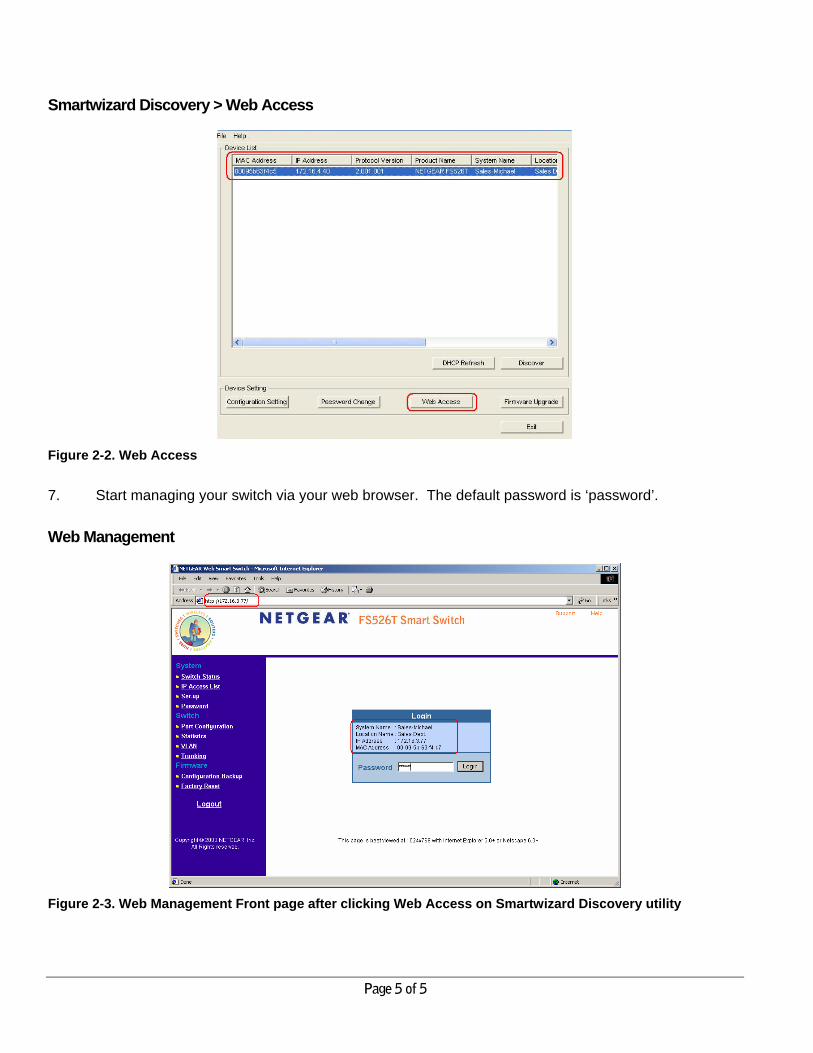
Select your switch by clicking on it. Then click on Web Access, as highlighted in Figure 2-2.
Smartwizard Discovery Utility > Discover
Figure 2-1. Smartwizard Discovery Utility Main Screen
Page 5 of 5
Smartwizard Discovery > Web Access
Figure 2-2. Web Access
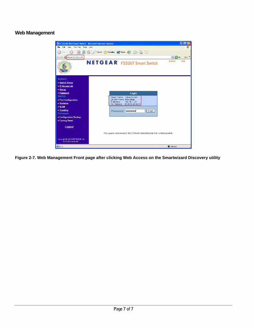
7. Start managing your switch via your web browser. The default password is ‘password’.
Web Management
Figure 2-3. Web Management Front page after clicking Web Access on Smartwizard Discovery utility
Page 6 of 6
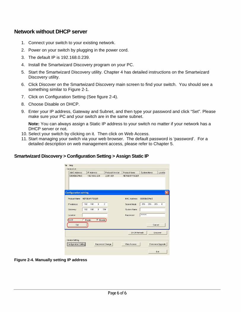
Network without DHCP server
1. Connect your switch to your existing network.
2. Power on your switch by plugging in the power cord.
3. The default IP is 192.168.0.239.
4. Install the Smartwizard Discovery program on your PC.
5. Start the Smartwizard Discovery utility. Chapter 4 has detailed instructions on the Smartwizard Discovery utility.
6. Click Discover on the Smartwizard Discovery main screen to find your switch. You should see a something similar to Figure 2-1.
7. Click on Configuration Setting (See figure 2-4).
8. Choose Disable on DHCP.
9. Enter your IP address, Gateway and Subnet, and then type your password and click “Set”. Please make sure your PC and your switch are in the same subnet.
Note: You can always assign a Static IP address to your switch no matter if your network has a DHCP server or not.
10. Select your switch by clicking on it. Then click on Web Access. 11. Start managing your switch via your web browser. The default password is ‘password’. For a
detailed description on web management access, please refer to Chapter 5.
Smartwizard Discovery > Configuration Setting > Assign Static IP
Figure 2-4. Manually setting IP address
Page 7 of 7
Web Management
Figure 2-7. Web Management Front page after clicking Web Access on the Smartwizard Discovery utility

Page 8 of 8
CHAPTER 3: Web Management Access Your NETGEAR Smart Switch series provides a built-in browser interface that lets you configure and manage it remotely using a standard Web browser such as Microsoft Internet Explorer or Netscape Navigator. This interface also allows for system monitoring of the switch. The help page will cover many of the basic functions and features of the switch and its web interface.
Web Management requires either Microsoft Internet Explorer 5.0 or later or Netscape Navigator 6.0 or later.
Note: Only one user can be logged in at any time.
Figure 5-1. Web Management Login page
There are 3 menu options available:
• System
• Switch
• Firmware
There is a Help Menu in the top of right side of screen. Click the help to read the full Help Menu. On some pages, there is a Help button. If you click that button, you will go to the part of the Help Menu that discusses that page.
Within the various browser interface pages, there are several buttons that you can use. Their names and functions are below:
Refresh: Pulls that screen’s data from current values on the system
Apply: Submits change request to system and refreshes screen data
Add: Add new entries to table information and refreshes screen data
Page 9 of 9
Browse: Locates a certain path for a desired file.
Delete: Deletes selected entries from table and refreshes screen data
Factory Reset: Restore the system factory default value.
Help: Goes to relevant section of Help Menu
System> Switch Status Page
The Switch Status page displays the port settings for both 10/100 Mbps and 10/100/1000 Mbps ports. To configure the ports, go to the Switch> Port Configuration page.
• ID: The port number on the switch
• Speed: Indicates the communication mode set for the port. The default setting for all ports is Auto-negotiation (Auto). The possible entries are Auto-negotiation (Auto), 10 Mbps half duplex (10M Half), 10 Mbps full duplex (10M Full), 100 Mbps half duplex (100M Half), 100 Mbps full duplex (100M Full), or Disable.
• Flow Control: Indicates whether Flow Control support is set for on (Enabled) or off (Disabled). The default setting for all ports is enabled.
• QOS: Indicate the priority for the port. The default setting for all ports is Normal. Quality of Service (QoS) is a way of managing traffic in a network, by treating different types of traffic with different levels of service priority. Higher priority traffic gets faster treatment during times of switch congestion.
• Link Status: Indicates the current speed and duplex for the port. DOWN means no link.
The next part of the Switch Status page shows the Virtual Local Area Network (VLAN) status. A VLAN is a way to electronically separate specified ports on the same switch into separate broadcast domains. By using VLAN, users can group by logical function instead of physical location. This switch supports 26 VLANs.
This page displays the port-based VLAN settings. The default VLAN setting is all ports belong to VLAN 1. To configure user-defined VLAN groups, go to the Switch> VLAN page.
Port Trunking is a feature that allows multiple links between switches to work as one virtual link (aggregate link). Trunks can be defined for similar port types only. For example, a 10/100 port cannot form a Port Trunk with a gigabit port. For 10/100 ports, trunks can only be formed within the same bank. A bank is a set of eight ports. Up to four trunks can be operating at the same time.
This page displays the Trunk status as shown in Figure 2-4. The default Trunk setting is all four groups disabled. To configure user-defined TURNK groups, go to the Switch> Trunking page.
If the IEEE802.1Q VLAN is enabled, this page will display the Tagged VLAN status as shown in Figures 2-5 and 2-6. To know more about Tag VLAN, see Switch> VLAN for details.
System> IP Access List Page
This page displays an IP access list, which lists switches that are allowed to login this Switch. The switch will only respond to requests from computers with the IP address in the list, so make sure you include your IP address if you are using this feature. This is a powerful way to limit remote access to your switch. The default setting is all host IP addresses allowed.

Page 10 of 10
Note: Once this new IP access is enabled, you can only access the switch via this IP. Make sure that your new IP is the same of current PC.
System> Set-up Page
This page will allow access to the system information parameters.
• Enter System Name and Location Name
• The DHCP function is enabled by default. Click Static IP Address to disable the DHCP function.
• Enter site-specific IP address, Subnet mask and Gateway in the appropriate boxes
• Click Apply to activate the setting
System> Password Page
The password entered is encrypted on the screen and will display as a sequence of asterisks (*). The default password is ‘password’ and can be changed here.
• Type the old password in the Old Password field
• Type the new password in the New Password field
• Re-type the new password in the Re-type New Password field
• Click Apply to activate the new password
Note: The password is case sensitive and with a maximum length of 20.
Switch Menu
There are 4 options available:
• Port Configuration
• Statistics
• VLAN
• Trunking
Switch> Port Configuration Page
You can configure the status per port by clicking a port ID at the port setting menu.
• ID: The port number on the switch. Click this number to configure the port.
• Speed: Indicates the communication mode set for the port. The default setting for all ports is Auto-negotiation (Auto). The possible entries are Auto-negotiation (Auto), 10 Mbps half duplex (10M Half),
Page 11 of 11
10 Mbps full duplex (10M Full), 100 Mbps half duplex (100M Half), 100 Mbps full duplex (100M Full), or Disable.
• Flow Control: Indicates whether Flow Control support is set for on (Enabled) or off (Disabled). The default setting for all ports is enabled.
• QOS: Indicate the priority for the port. The default setting for all ports is Normal. Quality of Service (QoS) is a way of managing traffic in a network, by treating different types of traffic with different levels of service priority. Higher priority traffic gets faster treatment during times of switch congestion.
• Link Status: Indicates the current speed and duplex for the port. DOWN means no link.
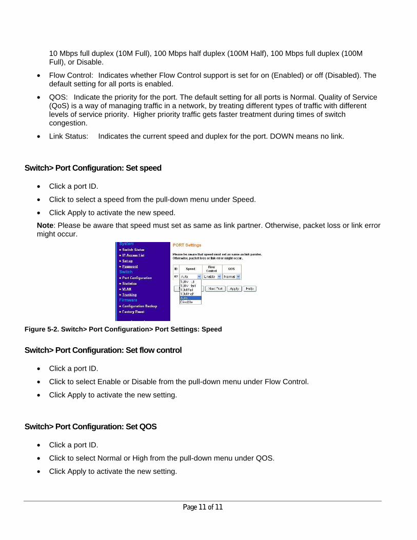
Switch> Port Configuration: Set speed
• Click a port ID.
• Click to select a speed from the pull-down menu under Speed.
• Click Apply to activate the new speed.
Note: Please be aware that speed must set as same as link partner. Otherwise, packet loss or link error might occur.
Figure 5-2. Switch> Port Configuration> Port Settings: Speed
Switch> Port Configuration: Set flow control
• Click a port ID.
• Click to select Enable or Disable from the pull-down menu under Flow Control.
• Click Apply to activate the new setting.
Switch> Port Configuration: Set QOS
• Click a port ID.
• Click to select Normal or High from the pull-down menu under QOS.
• Click Apply to activate the new setting.
Page 12 of 12
Switch> Statistics Page
The Statistics Table shows the statistics types for one port over time.
• ID: The port number on the switch
• Tx: Transmitted packet/s.
• Rx: Received packet/s.
• Tx Error: Transmitted packet/s with error.
• Rx Error: Received packet/s with error.
Packets are counted as TX Error if they:
• Had a late collision detected during the transmission (512 bit-times into the transmission).
• Experienced 16 failed transmission attempts due to collision.
• Were dropped due to lack of resources.
Packets are counted as RX Error if they:
• Were less than 64 bytes or greater than 1522 bytes?
• Had a bad FCS.
• Were dropped due to lack of resources.
Switch> Statistics> Refresh
Click Refresh to obtain current statistics data.
Switch> Statistics> Clear Counter
Click Clear Counter to start new statistics over time.
Switch> VLAN Page
A Virtual Local Area Network (VLAN) is a means to electronically separate ports on the same switch from a single broadcast domain into separate broadcast domains. By using VLAN, users can group by logical function instead of physical location.
The VLAN Table shows two types of VLAN and other information:
• IEEE 802.1Q VLAN (Tagged VLAN)
• Port-based VLAN
• ID: The port number on the switch
• Description: User-definable
• Member: Indicates which port/s belong to a VLAN group
Page 13 of 13
Switch> VLAN> Port-based VLAN
Depending on your model, there are up to 26 port-based VLAN groups supported on this switch, any one port can belong to different VLAN groups.
The default VLAN group port-based VLAN that have all ports belonging to VLAN 1.
Change members
• Click a VLAN ID as shown in Figure 5-16
• Click to select port/s for VLAN members
• Click Apply to activate the new setting Add VLAN
• Click Add VLAN.
• Enter a description for this VLAN
• Click to select port/s for VLAN members or click Set all to select all ports
• Click Clear all to unselect all ports
• Click Apply to activate the new setting
Delete VLAN
• Click Delete VLAN
• Click to select a VLAN ID
• Click Apply to confirm delete this VLAN
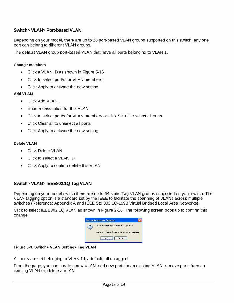
Switch> VLAN> IEEE802.1Q Tag VLAN
Depending on your model switch there are up to 64 static Tag VLAN groups supported on your switch. The VLAN tagging option is a standard set by the IEEE to facilitate the spanning of VLANs across multiple switches (Reference: Appendix A and IEEE Std 802.1Q-1998 Virtual Bridged Local Area Networks).
Click to select IEEE802.1Q VLAN as shown in Figure 2-16. The following screen pops up to confirm this change.
Figure 5-3. Switch> VLAN Setting> Tag VLAN
All ports are set belonging to VLAN 1 by default, all untagged.
From the page, you can create a new VLAN, add new ports to an existing VLAN, remove ports from an existing VLAN or, delete a VLAN.
Page 14 of 14
Add a port to a VLAN Group
• Under the VLAN ID drop down menu, select the VLAN you want to edit.
• Click the box below the port number so that a ‘T’ (tagged) or ‘U’ (untagged) appears.
• Click Apply. Remove a port from a VLAN Group
• Click the box again until a blank box appears. This will remove VLAN membership from the port.
• Click Apply.
Note: The default PVID of all ports is 1; therefore, you cannot remove any ports for the default Tag VLAN. It means that before removing any desired port from default Tag VLAN, changes PVID of such desired port to the PVID other than 1. Create a new VLAN Group
• Under the VLAN ID drop down menu, select Add new VLAN.
• Enter the VLAN ID “2” in the provided fields. VLAN ID must be set within 2 ~ 4094.
• Add VLAN members if so desired; click the box below the port number so that a ‘T’ (tagged) or ‘U’ (untagged) appears.
• Click Apply.
Note: To allow untagged packets to participate in VLAN 2, make sure to change the Port VLAN Ids (PVID) for the relevant ports. Access the PVID Settings by using the VLAN ID drop down menu.
Delete a VLAN Group
• Under the VLAN ID drop down menu, select the VLAN you want to remove.
• Click to select Remove VLAN.
• Click Apply.
PVID Setting
All untagged packets entering the switch will by default be tagged with the port’s Primary VLAN Identification (PVID). This screen allows you to specify the PVID for each port.
Take VLAN 2 for example: ports 5, 6, 7, and 8 have been checked as tagged ports for this VLAN. You must change the PVID value from “1” to “2” for those ports to avoid losing untagged packets when they are received.
Under the VLAN ID drop down menu, select PVID Setting. See below for an example of setting PVID for VLAN 2.
Change the PVID value of ports 5, 6, 7, and 8.
Click Apply.
Page 15 of 15
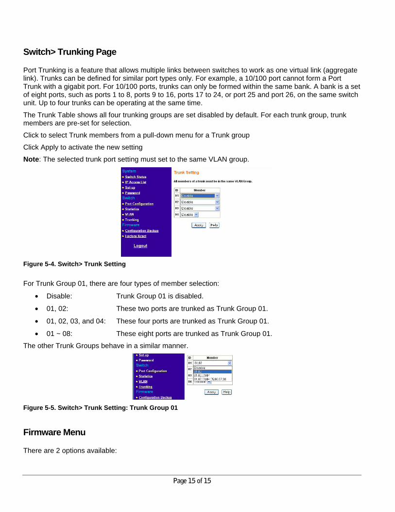
Switch> Trunking Page
Port Trunking is a feature that allows multiple links between switches to work as one virtual link (aggregate link). Trunks can be defined for similar port types only. For example, a 10/100 port cannot form a Port Trunk with a gigabit port. For 10/100 ports, trunks can only be formed within the same bank. A bank is a set of eight ports, such as ports 1 to 8, ports 9 to 16, ports 17 to 24, or port 25 and port 26, on the same switch unit. Up to four trunks can be operating at the same time.
The Trunk Table shows all four trunking groups are set disabled by default. For each trunk group, trunk members are pre-set for selection.
Click to select Trunk members from a pull-down menu for a Trunk group
Click Apply to activate the new setting
Note: The selected trunk port setting must set to the same VLAN group.
Figure 5-4. Switch> Trunk Setting
For Trunk Group 01, there are four types of member selection:
• Disable: Trunk Group 01 is disabled.
• 01, 02: These two ports are trunked as Trunk Group 01.
• 01, 02, 03, and 04: These four ports are trunked as Trunk Group 01.
• 01 ~ 08: These eight ports are trunked as Trunk Group 01.
The other Trunk Groups behave in a similar manner.
Figure 5-5. Switch> Trunk Setting: Trunk Group 01
Firmware Menu
There are 2 options available:
Page 16 of 16
• Configuration Backup
• Factory Reset
Firmware> Configuration Backup Page
You can backup the system and switch settings to your workstation. This can help you to reconfigure the switch quickly if you have to re-set to factory defaults. Additionally, if you want to try out different configurations on the switch, this feature will enable you to quickly return to a previous configuration.
If you own several switches and you want them to have the same configuration, you can use this feature to duplicate the settings to each switch.
Saving your Backup file:
• Click Backup to store the current setting to a file in your PC.
• Follow the instructions on the screen to select where you want to store your Backup file.
Restoring your Backup file (or using a duplicate configuration):
• Click Restore to recover the Backup file from your PC to the current switch. If you do not want to type in the path name, click Browse to find the Backup file.
• Click OK in the File Download dialog box.
• When download process is finished, click OK to confirm disconnection of current browser connection.
Note: Please be aware that the switch will reboot after a successful restore.
Note: The Backup file does not affect the password and MAC address of the switch
Firmware> Factory Reset Page
You can always reset the switch to default values by using this function.
• Click Factory Reset to enable this function
• When reset process is finished, click OK to confirm disconnection of current browser connection as shown in Figure 5-34.
Note: Please be aware that the switch will reboot after a successful reset.
Logout
When finished with all configuration and settings, click Logout to disconnect the current browser connection. The login page will pop up.

Page 17 of 17
CHAPTER 4: Software Upgrade Procedure The application software for the Smart Switch is upgradeable, enabling your switch to take advantage of improvements and additional features as they become available. The upgrade procedure and the required equipment are described in the following section. The upgrade procedure is as follows:
1. Save the new firmware to your computer. 2. Start the Smartwizard Discovery utility program.
3. Select your switch by clicking on it.
4. Then click on Firmware Upgrade, as highlighted in Figure 3-1.
Figure 3-1. Select the switch you want to upgrade and click Firmware Upgrade.
Figure 3-2. Locate New Firmware.
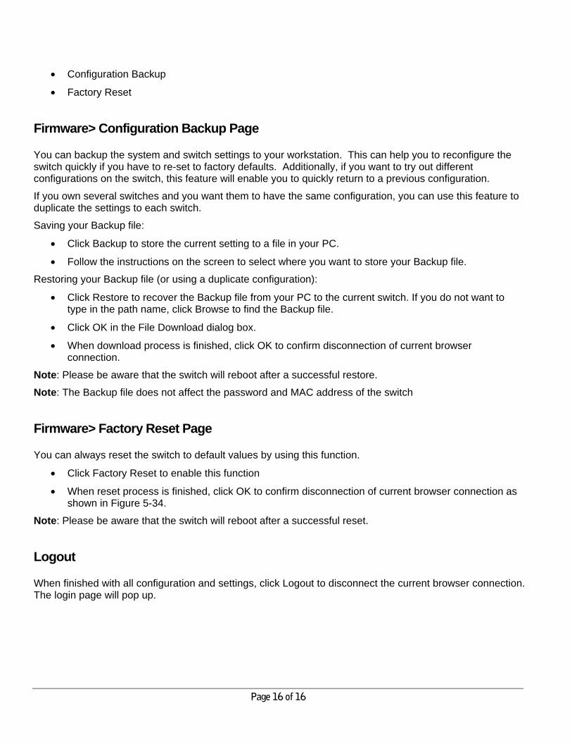
5. Enter the location of the new firmware in the Firmware path below Firmware setting. Alternatively, you can click Browse to locate the file. See Figure 3-2.
6. Click Start to download the new firmware file in non-volatile memory.
Page 18 of 18
Figure 3-3. Enter Password and click Start.
Note: Once the system finishes firmware upgrade process, the switch will automatically reboot. The Smartwizard Discovery utility will determine success of upgrade process based on the success of the
system reboot.
Page 19 of 19
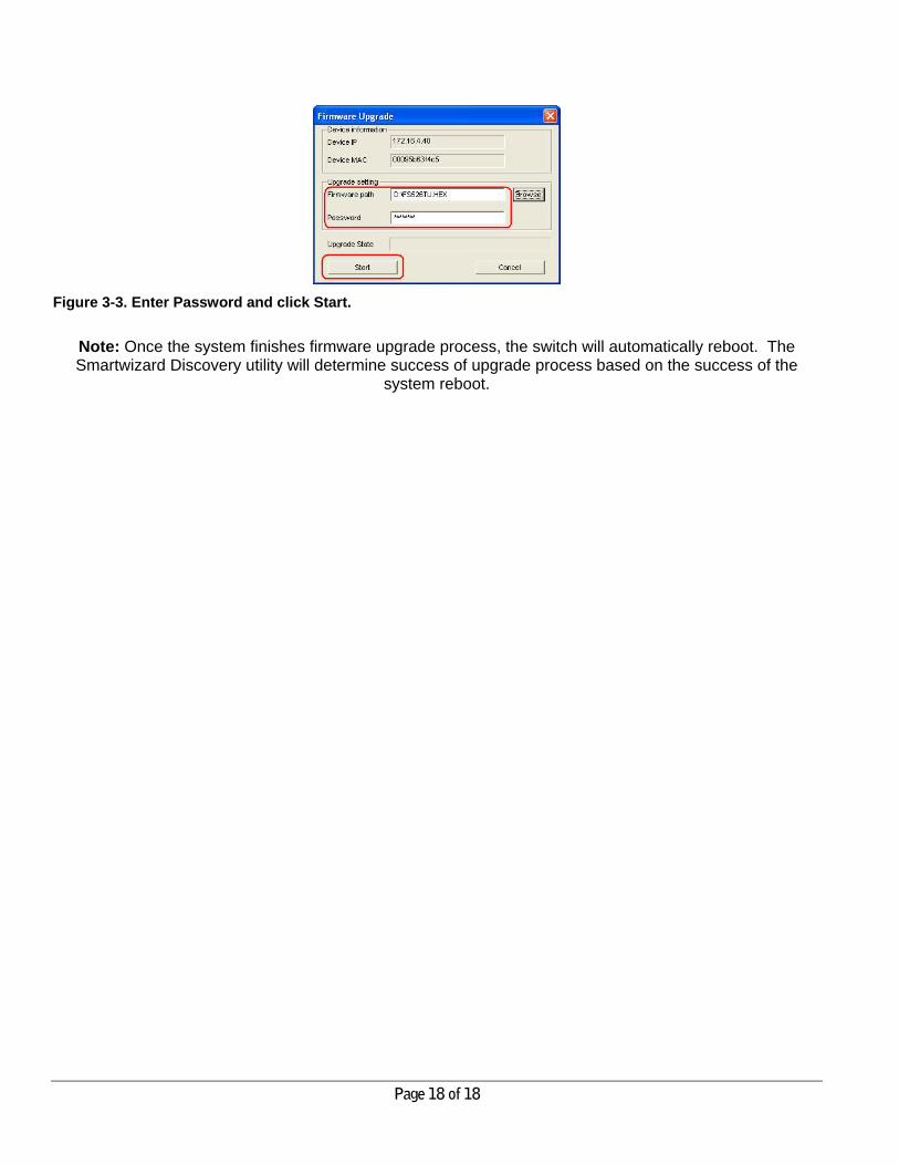
APPENDIX A: DEFAULT SETTINGS This appendix provides default settings for the NETGEAR Smart Switches. You can always configure the switch to default settings by using the Factory Reset function from a Web browser. Table A-1. Default Settings
FEATURE DEFAULT SETTING
Port Speed Auto-negotiation Port Duplex Auto-negotiation Flow Control (half duplex) Enabled Flow Control (full duplex) Enabled IP Configuration DHCP enabled Password password VLAN Port-Based VLAN Link Aggregation (Trunk) Disabled Traffic Prioritization (QoS) Optimized for flow control, all ports set normal priority
Page 20 of 20
APPENDIX B: IEEE 802.1Q VLAN A Local Area Network (LAN) can generally be defined as a broadcast domain. Hubs, bridges or switches in the same physical segment or segments connect all end node switches. End nodes can communicate with each other without the need for a router. Routers connect LANs together, routing the traffic to appropriate port.
A virtual LAN (VLAN) is a local-area network with a definition that maps workstations on some other basis than geographic location (for example, by department, type of user, or primary application). To communicate between VLANs, traffic must go through a router, just as if they were on two separate LANs.
A VLAN is a group of PCs, servers and other network resources that behave as if they were connected to a single, network segment — even though they may not be. For example, all marketing personnel may be spread throughout a building. Yet if they are all assigned to a single VLAN, they can share resources and bandwidth as if they were connected to the same segment. The resources of other departments can be invisible to the marketing VLAN members, accessible to all, or accessible only to specified individuals, depending on how the IT manager has set up the VLANs.
The Advantages of VLANs
Easy to do network segmentation Users communicate most frequently with each other can be grouped into common VLANs, regardless of physical location. Each group's traffic is largely contained within the VLAN, reducing extraneous traffic and improving the efficiency of the whole network.
Easy to manage The addition of nodes, as well as moves and other changes can be dealt with quickly and conveniently from a management interface rather than the wiring closet.
Increased performance VLANs free up bandwidth by limiting node-to-node and broadcast traffic throughout the network.
Enhanced network security
VLANs create virtual boundaries that can only be crossed through a router. So standard, router-based security measures can be used to restrict access to each VLAN
IEEE 802.1Q VLANs
Packets received by the switch will be treated in the following way: o When an untagged packet enters a port, it will be automatically tagged with the port’s default VLAN
ID tag number. Each port has a default VLAN ID setting that is user configurable (the default setting is 1). The default VLAN ID setting for each port can be changed in PVID Setting page.
o When a tagged packet enters a port, the tag for that packet will be unaffected by the default VLAN ID Setting.
o The packet will now proceed to the VLAN specified by its VLAN ID tag number. o If the port in which the packet entered does not have membership with the VLAN specified by the
VLAN ID tag, the packet will be dropped. o If the port has membership to the VLAN specified by the packet’s VLAN ID, the packet will be able
to be sent to other ports with the same VLAN ID membership.
Page 21 of 21
o Packets leaving the switch will be either tagged or untagged depending on the setting for that port’s VLAN membership properties. A ‘U’ for a given port means that packets leaving the switch from that port will be Untagged. Inversely, a ‘T’ for a given port means that packets leaving the switch from that port will be tagged with the respective VLAN ID in which it participated in.
The example given in this section will step through a more elaborate setup illustrating all possible scenarios for a comprehensive understanding of tagged VLANs.
Example
This example demonstrates several scenarios of VLAN use and how the switch will handle Tagged and Untagged traffic.
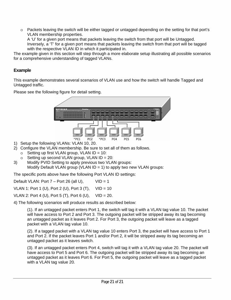
Please see the following figure for detail setting.
1) Setup the following VLANs: VLAN 10, 20. 2) Configure the VLAN membership. Be sure to set all of them as follows.
o Setting up first VLAN group, VLAN ID = 10: o Setting up second VLAN group, VLAN ID = 20:
3) Modify PVID Setting to apply previous two VLAN groups: Modify Default VLAN group (VLAN ID = 1) to apply two new VLAN groups:
The specific ports above have the following Port VLAN ID settings:
Default VLAN: Port 7 – Port 26 (all U), VID = 1
VLAN 1: Port 1 (U), Port 2 (U), Port 3 (T), VID = 10
VLAN 2: Port 4 (U), Port 5 (T), Port 6 (U), VID = 20.
4) The following scenarios will produce results as described below:
(1). If an untagged packet enters Port 1, the switch will tag it with a VLAN tag value 10. The packet will have access to Port 2 and Port 3. The outgoing packet will be stripped away its tag becoming an untagged packet as it leaves Port 2. For Port 3, the outgoing packet will leave as a tagged packet with a VLAN tag value 10.
(2). If a tagged packet with a VLAN tag value 10 enters Port 3, the packet will have access to Port 1 and Port 2. If the packet leaves Port 1 and/or Port 2, it will be stripped away its tag becoming an untagged packet as it leaves switch.
(3). If an untagged packet enters Port 4, switch will tag it with a VLAN tag value 20. The packet will have access to Port 5 and Port 6. The outgoing packet will be stripped away its tag becoming an untagged packet as it leaves Port 6. For Port 5, the outgoing packet will leave as a tagged packet with a VLAN tag value 20.
Page 22 of 22
APPENDIX C: Port-based VLAN Port-based VLAN will help efficiently confine the broadcast traffic to the switch ports. This switch allows up to 26 port-based VLAN groups, any one port can belong to different VLAN groups. The default VLAN group port-based VLAN that have all ports belonging to VLAN 1.
Port-based VLANs
Packets received by the switch will be treated in the following way: o When a packet enters a port, it only can proceed to the VLAN which the port belongs to. The packet
will be able to be sent to other ports with the same VLAN ID membership. o If the port in which the packet entered does not have membership with the same VLAN as the
source port does, the packet will be dropped.
Example
This example basically demonstrates how the port-based VLANs work to meet your needs.
Setup the following VLANs, each with defined descriptions: VLAN 1 (IT department) VLAN 2 (Sales department) VLAN 3 (Marketing department) VLAN 4 (Accounting department).
Configure the VLAN membership. Be sure to set all of them as follows. Setting up second VLAN group (Sales), VLAN ID = 02, with membership of ports 1~8, 25. Setting up third VLAN group (Marketing), VLAN ID = 03, with membership of ports 7~14, 25. Setting up fourth VLAN group (Accounting), VLAN ID = 04, with membership of ports 19~20, 25. Setting up first VLAN group (IT), VLAN ID = 01, with membership of all ports.
Since VLAN ID 01 has been setup by default, you will have to remove the ports that belong to all other VLAN group except port 25.
Ports 7 and 8 are kept for the usage of connecting file server and printer server. Sales and Marketing departments can share file archives and printing services.
Port 25 provides Gigabit speed for email server and Internet connection.
The specific ports above have the following functions:
VLAN 1: Port 15 – Port 18, Port 21 – Port 24, Port 26, for IT department to monitor and control activities on all other VLANs
VLAN 2: Port 1 – Port 8, for Sales department, port 7 and 8 connect to file archives and printer server.
VLAN 3: Port 7 – Port 14, for Marketing department, port 7 and 8 connect to file archives and printer server.
VLAN 4: Port 19 – Port 20, for Accounting department, its work is kept secret from other departments except IT.
Scenarios:
If a packet comes in on port 2, it can go to ports 1, 3, 4, 5, 6, 7, 8, and 25, as those are the only ports in that VLAN. A Sales person on Port 2 can get to the Internet, send and receive email, but cannot access the marketing department print server or file archives.

Page 23 of 23
If a Marketing user sends out a broadcast message, the Sales and Accounting departments will not be affected by the message, as it will not go out on their ports. Only the Marketing department and the IT group will get the broadcast message.
If an IT user sends out a broadcast message, everyone will get it.