Embed Size (px)
Citation preview
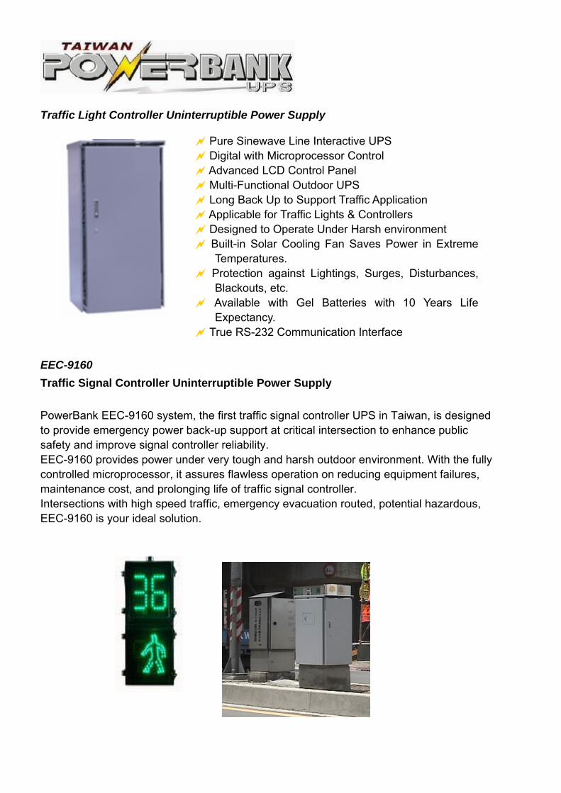
Traffic Light Controller Uninterruptible Power Supply
EEC-9160
Traffic Signal Controller Uninterruptible Power Supply
PowerBank EEC-9160 system, the first traffic signal controller UPS in Taiwan, is designed to provide emergency power back-up support at critical intersection to enhance public safety and improve signal controller reliability. EEC-9160 provides power under very tough and harsh outdoor environment. With the fully controlled microprocessor, it assures flawless operation on reducing equipment failures, maintenance cost, and prolonging life of traffic signal controller. Intersections with high speed traffic, emergency evacuation routed, potential hazardous, EEC-9160 is your ideal solution.
Pure Sinewave Line Interactive UPS Digital with Microprocessor Control Advanced LCD Control Panel Multi-Functional Outdoor UPS Long Back Up to Support Traffic Application Applicable for Traffic Lights & Controllers Designed to Operate Under Harsh environment Built-in Solar Cooling Fan Saves Power in Extreme
Temperatures. Protection against Lightings, Surges, Disturbances,
Blackouts, etc. Available with Gel Batteries with 10 Years Life
Expectancy. True RS-232 Communication Interface
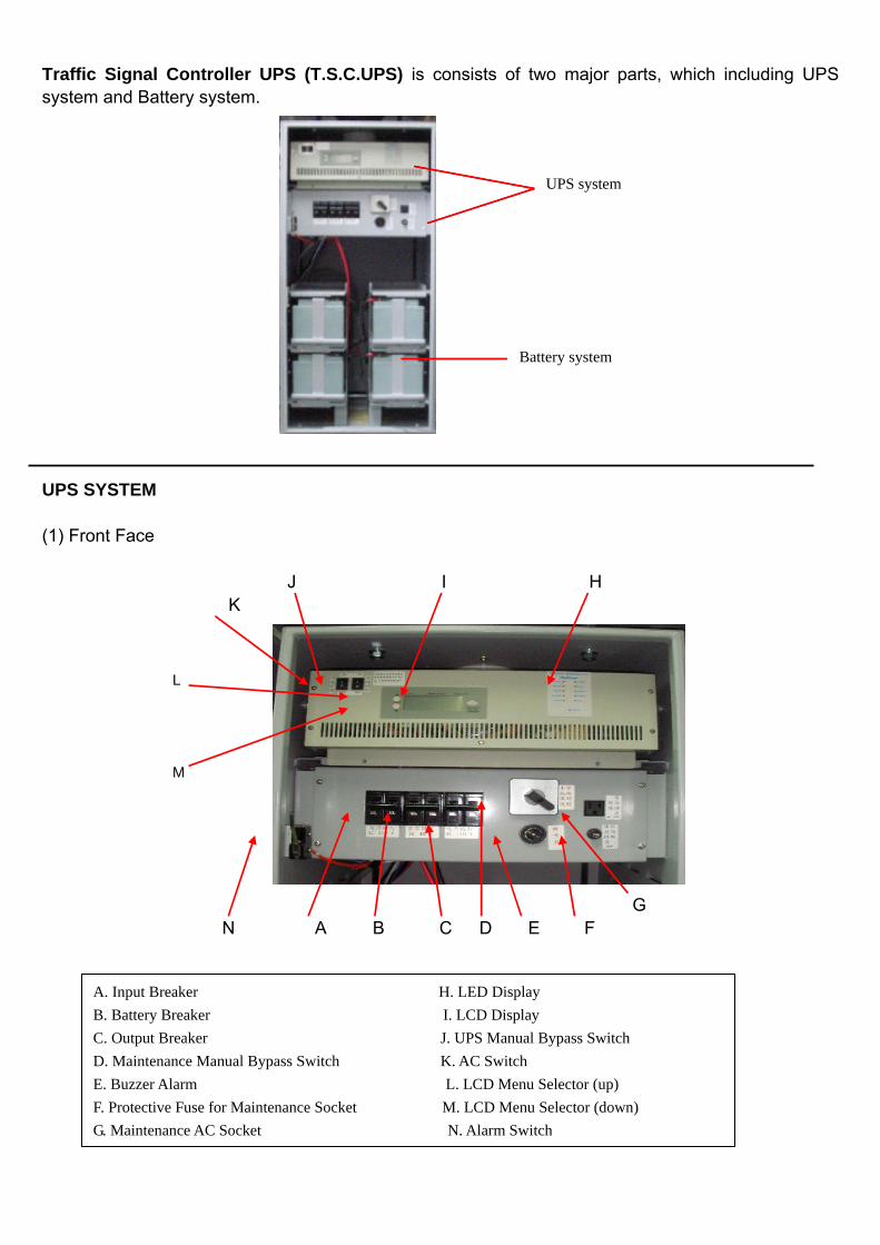
Traffic Signal Controller UPS (T.S.C.UPS) is consists of two major parts, which including UPS system and Battery system. UPS SYSTEM (1) Front Face J I H K
G N A B C D E F
UPS system
Battery system
A. Input Breaker H. LED Display
B. Battery Breaker I. LCD Display
C. Output Breaker J. UPS Manual Bypass Switch
D. Maintenance Manual Bypass Switch K. AC Switch
E. Buzzer Alarm L. LCD Menu Selector (up)
F. Protective Fuse for Maintenance Socket M. LCD Menu Selector (down)
G. Maintenance AC Socket N. Alarm Switch
L
M
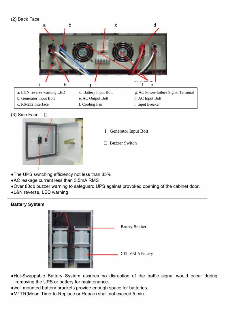
(2) Back Face a b c d
i h g f e (3) Side Face Ⅱ
Ⅰ ●The UPS switching efficiency not less than 85% ●AC leakage current less than 3.5mA RMS ●Over 80db buzzer warning to safeguard UPS against provoked opening of the cabinet door. ●L&N reverse, LED warning Battery System ●Hot-Swappable Battery System assures no disruption of the traffic signal would occur during
removing the UPS or battery for maintenance. ●well mounted battery brackets provide enough space for batteries. ●MTTR(Mean-Time-to-Replace or Repair) shall not exceed 5 min.
Ⅰ. Generator Input Bolt Ⅱ. Buzzer Switch
GEL VRLA Battery
Battery Bracket
a. L&N reverse warning LED d. Battery Input Bolt g. AC Power-failure Signal Terminal
b. Generator Input Bolt e. AC Output Bolt h. AC Input Bolt
c. RS-232 Interface f. Cooling Fan i. Input Breaker
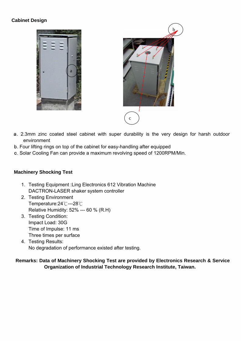
Cabinet Design
○a. 2.3mm zinc coated steel cabinet with super durability is the very design for harsh outdoor
environment ○b. Four lifting rings on top of the cabinet for easy-handling after equipped
○c. Solar Cooling Fan can provide a maximum revolving speed of 1200RPM/Min. Machinery Shocking Test
1. Testing Equipment :Ling Electronics 612 Vibration Machine
DACTRON-LASER shaker system controller 2. Testing Environment
Temperature:24℃---28℃ Relative Humidity: 52% --- 60 % (R.H)
3. Testing Condition: Impact Load: 30G Time of Impulse: 11 ms Three times per surface
4. Testing Results: No degradation of performance existed after testing.
Remarks: Data of Machinery Shocking Test are provided by Electronics Research & Service Organization of Industrial Technology Research Institute, Taiwan.
b
a
c
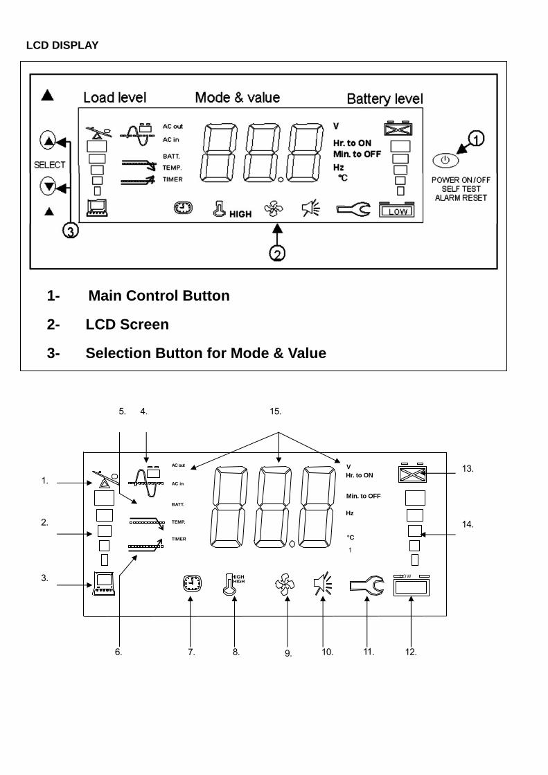
LCD DISPLAY
1- Main Control Button
2- LCD Screen
3- Selection Button for Mode & Value
HIGH
1.
2.
3.
4. 5. 15.
6. 7. 8. 9. 10. 11. 12.
13.
14.
AC in
TEMP.
TIMER
AC out
BATT.
VHr. to ON
Min. to OFF
Hz
°C
1
L OW HIGH
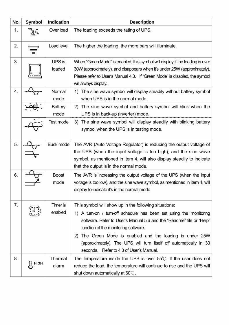
No. Symbol Indication Description
1.
Over load The loading exceeds the rating of UPS.
2.
Load level The higher the loading, the more bars will illuminate.
3. UPS is
loaded
When “Green Mode” is enabled, this symbol will display if the loading is over
30W (approximately), and disappears when it’s under 25W (approximately).
Please refer to User’s Manual 4.3. If “Green Mode” is disabled, the symbol
will always display.
4.
Normal
mode
1) The sine wave symbol will display steadily without battery symbol
when UPS is in the normal mode.
Battery
mode
2) The sine wave symbol and battery symbol will blink when the
UPS is in back-up (inverter) mode.
Test mode 3) The sine wave symbol will display steadily with blinking battery
symbol when the UPS is in testing mode.
5.
Buck mode The AVR (Auto Voltage Regulator) is reducing the output voltage of
the UPS (when the input voltage is too high), and the sine wave
symbol, as mentioned in item 4, will also display steadily to indicate
that the output is in the normal mode.
6.
Boost
mode
The AVR is increasing the output voltage of the UPS (when the input
voltage is too low), and the sine wave symbol, as mentioned in item 4, will
display to indicate it’s in the normal mode
7. Timer is
enabled
This symbol will show up in the following situations:
1) A turn-on / turn-off schedule has been set using the monitoring
software. Refer to User’s Manual 5.6 and the “Readme” file or “Help”
function of the monitoring software.
2) The Green Mode is enabled and the loading is under 25W
(approximately). The UPS will turn itself off automatically in 30
seconds. Refer to 4.3 of User’s Manual.
8.
Thermal
alarm
The temperature inside the UPS is over 55 . If the user does not ℃
reduce the load, the temperature will continue to rise and the UPS will
shut down automatically at 60 .℃
HIGH
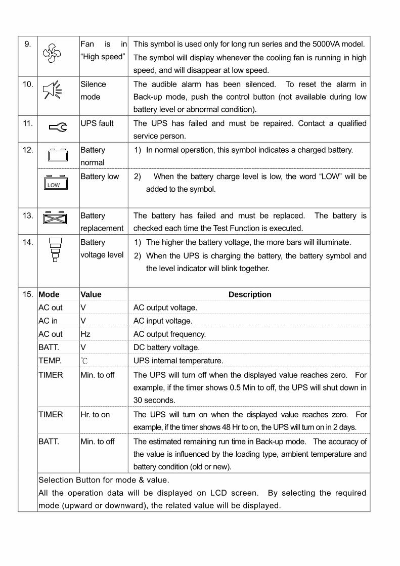
9. Fan is in
“High speed”
This symbol is used only for long run series and the 5000VA model.
The symbol will display whenever the cooling fan is running in high
speed, and will disappear at low speed.
10.
Silence
mode
The audible alarm has been silenced. To reset the alarm in
Back-up mode, push the control button (not available during low
battery level or abnormal condition).
11. UPS fault The UPS has failed and must be repaired. Contact a qualified
service person.
12. Battery
normal
1) In normal operation, this symbol indicates a charged battery.
Battery low 2) When the battery charge level is low, the word “LOW” will be
added to the symbol.
13. Battery
replacement
The battery has failed and must be replaced. The battery is
checked each time the Test Function is executed.
14.
Battery
voltage level
1) The higher the battery voltage, the more bars will illuminate.
2) When the UPS is charging the battery, the battery symbol and
the level indicator will blink together.
15. Mode Value Description
AC out V AC output voltage.
AC in V AC input voltage.
AC out Hz AC output frequency.
BATT. V DC battery voltage.
TEMP. ℃ UPS internal temperature.
TIMER Min. to off The UPS will turn off when the displayed value reaches zero. For
example, if the timer shows 0.5 Min to off, the UPS will shut down in
30 seconds.
TIMER Hr. to on The UPS will turn on when the displayed value reaches zero. For
example, if the timer shows 48 Hr to on, the UPS will turn on in 2 days.
BATT. Min. to off The estimated remaining run time in Back-up mode. The accuracy of
the value is influenced by the loading type, ambient temperature and
battery condition (old or new).
Selection Button for mode & value.
All the operation data will be displayed on LCD screen. By selecting the required
mode (upward or downward), the related value will be displayed.
LOW