Embed Size (px)
Citation preview
Traffic Signal Management and Operations: A Basic Service Plan

ACKNOWLEDGEMENT Special thanks goes to Richard Denney, and Paul Olson with the Federal Highway Administration’s Resource Center for their collaboration on this document. Rick and Paul’s insight, and review proved extremely valuable.

PREFACE “Objectives are not fate; they are direction. They are not commands; they are commitments. They do not determine the future; they are means to mobilize the resources and energies of the business for the making of the future.” Peter F. Drucker Traffic signals are ideally installed because other forms of traffic control devices are not as effective at efficiently moving traffic throughout the day. Working from this perspective, establishing specific objectives for managing the Town’s traffic signal infrastructure is critical for ensuring that signals are operating at their most efficient levels. Efficiency at its core is: performing or functioning in the best possible manner with the least waste of time and effort. How should this translate to the Town’s signals? Through an informal survey of what some drivers expect from signal operations, some central themes developed: “I want signal timings to be as responsive as possible to changing patterns” “I’m okay with waiting on a side street, but not if traffic is nonexistent on the main street” “During congested times, I’m okay with not making it through one full cycle, but not two” “I expect the impact on my travel to be predictable” Distilled down, the majority of the traveling public desires to be treated equitably, consistently, and in a manner that appears to make sense when they encounter traffic signals. The goal of this document is to identify what constitutes good basic service to our citizens, and what we need to do to ensure that we provide that good basic service.1 Objectives need to touch on all aspects of signals from intersection control assessment through design, construction, timing development, operations, and maintenance. Traffic signal management by objectives will guide the Town toward the vision of treating the traveling public in the most fair and efficient manner possible.
1 Improving Traffic Signal Management and Operations: A Basic Service Model http://www.ops.fhwa.dot.gov/publications/fhwahop09055/sigopsmgmt_v.htm

Table of Contents
Chapter 1 Objectives and Requirements Page 1
Chapter 2 Public Relations Protocols Page 3
Chapter 3 Maintenance Strategies Page 6
Chapter 4 Operations Strategies Page 8
Chapter 5 Design Strategies Page 12

1
Chapter 1 Objectives and Requirements The Town of Castle Rock is a physically separated and distinct community located south of the Denver metropolitan area. Interstate 25 (I-25) is a major transportation corridor that attracts many vehicle trips to and from the community. Additionally, many businesses and industries have discovered Castle Rock as an ideal place to locate. The orientation of the Town’s arterial street network, where the Town’s existing traffic signals are located, combined with the two elements listed above lead to two distinct travel patterns:
1. Peak weekday periods when travel to/from I-25 is heavy, and 2. Off-peak periods where origin and destinations among land uses within Castle
Rock tend to govern traffic patterns The following are the principal operational objectives that form the nucleus for which all signal activities will revolve around: Key Objective #1: During weekday peak hours, we will do our best to ensure the smooth flow of traffic on the main streets to and from I-25. We will strive to minimize main street stops, but when stops must occur, we will make them brief, within the context of safe operation. Key Objective #2: During off-peak hours, we will do our best to equitably serve land uses such that queues and cycle failures2 are minimized. These two primary objectives, while not specific, are concrete and are the foundation for the establishment of high-level requirements. Key Requirements
1. Maximize the percentage of time that motorists encounter what we expect them to encounter (i.e. are timing plans and equipment running as we expect?).
2. Smooth flow during weekday peak periods must minimize main street stops
and delays to travel time.
3. Versatile timing plans that operate well over a range of vehicle flows and patterns.
2 A cycle failure is when a vehicle waiting at a red light is not able to make it through on a single green indication. Traffic Signal Timing Manual http://ops.fhwa.dot.gov/arterial_mgmt/tstmanual.htm

2
4. Minimize queue length and cycle failures during uncongested off-peak periods. By doing this, access to various land uses is maximized.
5. Maximize vehicle throughput on the main street, and manage vehicle queue
lengths to minimize their effect on the overall corridor during congested periods.
6. Simplify hardware and software needs when possible.

3
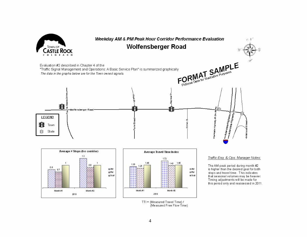
Chapter 2 Public Relations Protocols Clear, direct, honest communication is the essential vehicle by which the Town’s values are demonstrated. This is the foundation of our interaction not only with Town Council, boards, commissions, and staff, but the public as well. This chapter lays out the standards that will be utilized when responding to all users of the Town’s traffic signals. Standard #1: All signal questions or comments received should be responded to in kind (phone calls with phone calls, emails with emails, etc.). Standard #2: All initial contacts should be initially returned by phone or email within two business days to notify a person that their question or comment has been received. This initial contact should be by the person managing the review or response. Standard #3: The Traffic Engineering and Operations Manager should personally answer all questions associated with traffic signal issues that are not malfunctions. Standard #4: The Traffic Engineering and Operations Manager should handle all contacts from the media regarding traffic signals. Coordination with the Community Relations Department should occur prior to the Traffic Engineering and Operations Manager agreeing to give a planned interview for print or broadcast. Standard #5: The Traffic Engineering and Operations Manager should be responsible for all presentations and reports to Town boards, commissions, and Town Council regarding signal procurement, installation, removal, and operations. Standard #6: An annual report will be prepared for the Assistant Public Works Director by the end of February for the proceeding year’s efforts. This report will contain the information and format shown in the sample report on page(s) 4 – 5.
4

5
6
Chapter 3 Maintenance Strategies This chapter lays out the Town’s approach to the maintenance of Town owned traffic signals. This chapter includes a clear explanation of how available staff and financial resources will be maximized to maintain existing equipment. This chapter outlines the strategies to meet the key requirement of “Maximizing the percentage of time that motorists encounter what we expect them to encounter”. Current Resources and Capabilities The current Traffic Engineering and Operations Division within the Public Works Department consists of two sections: 1) Engineering, and 2) Signs and Markings. It’s the Engineering Section that handles the operations and maintenance responsibilities for the Town’s signal infrastructure. There are currently two full time employees that make up the Engineering Section: 1) Traffic Engineering and Operations Manager, and 2) Sr. Engineering Technician. The ability to provide signal equipment maintenance using in-house staff is minimal, and is limited to basic controller troubleshooting. All equipment replacement and repair is handled through contracted maintenance. An annual service contract exists with a signal contractor. They provide quarterly preventative maintenance on all traffic signals as detailed in the separate traffic signal maintenance agreement. All other calls for unscheduled maintenance activities are covered via unit pricing as reported by the Town. The contractor maintains a 24-hour, 365-day/year call center for all maintenance related calls and must respond per terms outlined within the service contract. This chapter will not cover existing terms of this service contract. A separate service contract exists for preventative maintenance associated with underground infrastructure locating services associated with contractor “dig” requests. Colorado requires that underground infrastructure owners maintain a database with the State’s one call center for facility locates when contractors dig. This service contract is also a unit price contract based on call requests that come from the division for traffic signal locates. Expenditures to maintain this operation arise from the State’s call center tickets, and all responding locates from the Town’s service contractor. The average 2010 expenditures related to contracted maintenance and power is $2,600/year/signal. This annual budget has been fairly steady for the past several years. The following maintenance strategies are based on the current staff and financial resources for contract maintenance and power costs. Maintenance Strategy #1: Continue to maintain all underground signal infrastructure with the State’s one call locate request center to minimize repair costs associated with damage from contractor digs.

7
Maintenance Strategy #2: Monthly visits to each signal by Town staff to observe video detection quality and operations. If possible, visits should cover varying light, and weather conditions. Maintenance Strategy #3: Conduct regular program upload and comparisons (monthly recommended) of all traffic signals to ensure correct timing plans are running. Ensure the contractor maintenance contract has a process to maintain traffic signal timings and procedures for timing change notification to the Traffic Engineering Division associated with maintenance activities. Maintenance Strategy #4: Maintain a requirement within the contractor maintenance contract to conduct preventative maintenance on all traffic signals to maximize equipment lifespan. Conduct yearly review of service contracts for signal maintenance and underground infrastructure locating to determine if refinement is necessary. A comparison of the number of trouble calls versus preventative maintenance frequencies should assist with optimizing a preventative maintenance schedule and tasks. Examples include: 1) Is current preventative maintenance schedule too lean, or excessive, 2) Is more detail required for existing checklists. A quality assurance check process should be built into the Town’s service contract. The quality assurance should require a person within the contractor’s agency that is at a higher level then the original inspecting crew. The Town’s contract manager should designate a date to meet the QA person at a location randomly chosen by the Town’s contract manager to complete a full inspection. Maintenance Strategy #5: Reduce the number of future signal installations to minimize equipment inventory by assessing alternative controls, such as roundabouts, during engineering reviews of unsignalized intersections. Maintenance Strategy #6: Conduct a regular visual inspection of mast arm style pole bases for corrosion. Welds should be sanded and repainted, and non-destructive testing conducted when indications of cracking or holes exist to ensure structural integrity of poles.

8
Chapter 4 Operations Strategies This chapter discusses both the operational approach to the Town’s traffic signals along with the evaluation to be undertaken for purposes of meeting the following key requirements listed in chapter #1:
1. Smooth flow during weekday peak periods must minimize main street stops and delays to travel time.
2. Versatile timing plans that operate well over a range of vehicle flows and
patterns.
3. Minimize queue length and cycle failures during uncongested off-peak periods.
4. Maximize vehicle throughput on the main street, and manage vehicle queue
lengths to minimize their effect on the overall corridor during congested periods.
Operations Approach Operations Strategy #1: Optimize cycle lengths, splits, and offsets of individual timing plans that are developed toward achieving the key requirements listed above. Operations Strategy #2: Strive for timing plan versatility such that the number of timing plans is kept to a minimum while still achieving the key requirements listed above. Operations Strategy #3: Utilize clearance (yellow change plus red clearance) times per the following:
A. Yellow = 1 + 1.47s / (20 + 64.4g) B. All Red = (w + 25) / 1.47s
Where: s = posted speed limit (mph) g = approach grade percentage (formatted as 0.0x or –0.0x) w = intersection width (ft) Note: for protected lefts, use left turning vehicle speed for s, and centerline path from stop bar to start of receiving lane length for w.
Operations Strategy #4: Utilize pedestrian detection (push button or detection zones) to activate pedestrian phases to broaden ability to optimize splits. This should be employed only at locations where pedestrian signal heads exist.

9
Operations Strategy #5: Utilize stop bar detection for side street approaches (excluding dedicated right turn lanes) and dedicated left turn lanes on main streets if protected left turn phases are warranted. The desired headway (greater than saturation headway) should be assessed for these movements to establish the appropriate detection length and passage time using the formula:
passage = h-((Lv + Ld)/v) Where: passage is the unoccupied detector time h = desired headway (s) (greater than saturation flow headway) Lv = vehicle length (ft) (default to passenger car design length – 19 ft) Ld = detection zone length (ft) v = vehicle speed (ft/sec) The passage time may vary by time of day in order to meet the respective key objective listed in chapter #1. Operations Strategy #6: Minimize the use of protected left turning phases. Protected left phases should be limited by time of day. Protected left turn phasing may be beneficial if some or all of the following conditions exist:
1. Volumes: # of Opposing Lanes If Left Turn Volume Should Exceed
1 Qo(C/g) < 1000 770(g/C) ‐ 0.634Qo
1000 < Qo(C/g) < 1350 480(g/C) ‐ 0.348Qo
2
Qo(C/g) < 1000 855(g/C) ‐ 0.500Qo
1000 < Qo(C/g) < 1350 680(g/C) ‐ 0.353Qo
1350 < Qo(C/g) < 2000 390(g/C) ‐ 0.167Qo
3
Qo(C/g) < 1000 900(g/C) ‐ 0.448Qo
1000 < Qo(C/g) < 1350 735(g/C) ‐ 0.297Qo
1350 < Qo(C/g) < 2400 390(g/C) ‐ 0.112Qo
Qo = opposing traffic volume, C = Cycle Length, g = effective green time
Note: Use judgement as to whether or not dedicated right turn lane and
associated volume should be included in calculation.
2. Delay:
a. Total estimated delay of all left turning volume in hour > 2 hours b. Min of 2 left turning vehicles/cycle c. Average delay for left turn vehicle is > 35 seconds
3. Accidents:
a. Single approach: 4 accidents/year, or 6 in two years b. 2 opposing approaches: 6/year, or 10 in two years
10
4. Sight Distance: When opposing left turns cannot see past one another to be able to observe safe gaps in opposing through traffic. Evaluation Approach This section deals with how the division will strive to ensure that operation on the streets meets the key objectives. Evaluation Strategy #1: Conduct an annual report of accidents on Town owned public streets, and use statistical modeling to assess whether infrastructure issues may be a contributing factor to accidents. Evaluation Strategy #2: Conduct floating car travel time studies to measure average number of stops and average delay during weekday AM and PM peak hours. If funding becomes available, use of blue tooth technology should be considered to replace the floating car method.
Averages will be based on a minimum of five runs along the corridor during each peak hour
All signal corridors will be assessed twice/year with a minimum of four months
between assessments. Reviews should try to cover all four quarters of the year in alternating years.
The following performance goals should be strived for (failure after attempts to
meet these goals through signal timing changes should be used to identify capacity improvement projects):
o Average number of stops per corridor less than or equal to 0.33
stops/signal o Average delay on main street < 45% of free flow travel time
Free flow time is the average measured time for a vehicle to travel between the starting and ending points on the corridor with zero stops or delays resulting from signal indications. Should be collected during low flow off-peak conditions. Calculated time may be used if above can’t be obtained.
(Travel Time Index – TTI = time penalty for a corridor on an average trip. A TTI of 1.45 indicates that a 60 second free flow time on the corridor takes 87 seconds)
Evaluation Strategy #3: Field assess each corridor during off peak periods to determine the dominant flow patterns. All signal corridors will be assessed twice/year with a minimum of four months between assessments. Reviews should try to cover all

11
four quarters of the year in alternating years. Both weekday and weekend off peak periods should be assessed and the following performance goals strived for:
Average delay for the heaviest volume pattern with a corridor < 45% of calculated free flow travel time (TTI < 1.45). Averages will be based on a minimum of five runs along the heaviest volume route.
Less than or equal to one queue block within 10 observed cycles on any
approach to a signal
Less than or equal to one cycle failure on any movement within 10 observed cycles at each signal

12
Chapter 5 Design Strategies The purpose of this chapter is to provide some design standards that are geared toward supporting the operations and maintenance strategies listed in the previous chapters. In addition, this chapter lays out the minimum steps to be taken when implementing new automated systems for either traffic signal operation or management (such as signal trouble call tracking). Design Strategy #1: The current Public Works design criteria will be utilized for all new signal installations. This ensures consistency, and compatibility with existing field equipment. Design Strategy #2: Design plans should incorporate pole, and mast arm configurations that minimize the amount of infrastructure to be maintained. For example, at T-intersections can a single pole and mast arm oriented diagonally adequately serve two approaches? Ensure that pole locations do not encroach on sidewalks if possible, but if unavoidable, ADA access requirements to curb ramps must be met. Design Strategy #3: The use of detection that is non-intrusive to the road pavement is preferred (video, microwave, etc.) to allow for future flexibility of zone set-ups, and minimize pavement damage for reduced repair costs and minimal disruption to travel resulting from lane closure needs. However, this should not be at the expense of achieving operational goals. If other detection technology decreases maintenance needs and meets operation goals, these should be utilized. Detection zones should be limited to stop bar detection. Limitations of detector technology should be understood under night and day light conditions. Video detectors should be mounted on the nearest pole to an approach to minimize the amount of horizon in view. Design Strategy #4: Utilize pedestrian push buttons on all pedestrian phases to allow for maximum flexibility of timing plan development. Pedestrian signal heads are required for all phases where push buttons are utilized. Design Strategy #5: Provide accessible pedestrian signals at locations where known support facilities for visually impaired citizens are nearby, or when requested by citizens during the planning stages when signalized locations are on a route currently used by visually impaired citizens. Design Strategy #6: The current MUTCD requirements for signal head locations shall be adhered to. Where discretion is allowed, signal heads should be placed directly over centerlines of all lanes to provide consistency for drivers (especially to assist with orientation of lanes when snow events occur).
13
Design Strategy #7: Communications equipment should be installed on all new signals and connected to the nearest system zone. Apply sound system engineering principals to all communications technology decisions to ensure that they support all anticipated activities of the agency. Minimum Steps to be Taken For Implementing New Systems The following steps should be utilized when systems such as signal system software changes, tracking, or infrastructure management systems are updated or procured. These steps assist with a consistent systems engineering approach to ensure that the Town obtains what it truly needs. The key objectives and high level requirements must be kept at the forefront when assessing new projects, and applications using these steps. This is a top down assessment approach. Step #1 Project Management Plan Step #2 Systems Engineering Management Plan Step #3 Concept of Operations: How will the system be used and by whom and for what purposes. Staff should write this document when possible to best think through the needs. If a consultant writes this document, the Traffic Engineering and Operations Division should be the primary audience. The focus of this step needs to be on what will be done with the new system, and not what features are desired. This step provides a model of the activities of the town staff, in detail, including how staff receives and responds to citizen complaints, how the signal timing database is managed, how the operation of the system is monitored, how future operations are evaluated, and so on. These activities should describe each step taken by staff, and the activities, taken together, describe the needs in detail. These needs will become the basis for requirements used to evaluate systems alternatives. The Traffic Engineering and Operations Division will confirm that the model of their activities as described in any proposed system Concept of Operations is accurate and representative of intentions. Step #4 Requirements: The activities described above will lead to requirements. For example, if staff intends to be responsive to the reporting of critical faults on a 24-hour full-time basis, that activity will lead to a requirement to provide a portable device that a person can carry anywhere and be notified of specific critical fault information. These requirements will become the standard for evaluating design and technology alternatives, and therefore the requirements themselves will be independent of design and technology prescriptions. The requirements will also be written to be easily and directly tested so that designers are able to efficiently demonstrate that their design is complete and correct, and so that staff is able to efficiently conduct verification and validation as shown below.

14
Step #5 Verification: This step will require the designer to demonstrate how each element of the design fulfills the requirements. It should also describe how the system will be tested to prove it conforms to the design. Step #6 Validation: This is where the implementer demonstrates that the system indeed supports the activities described in the concept of operations.