Embed Size (px)
Citation preview
5-8Sc2400 Technical Manual
CHAPTER 5. POWER TRAIN-HYDROSTATIC3. Theory of Operation
3-1 Principle
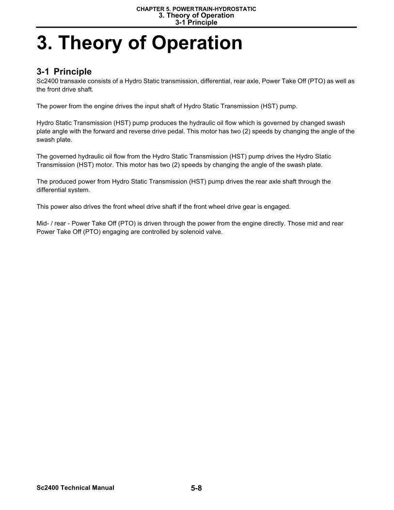
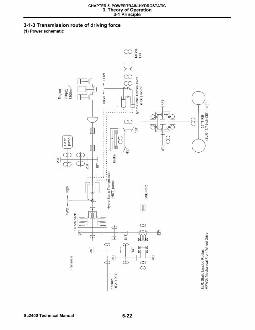
3. Theory of Operation3-1 PrincipleSc2400 transaxle consists of a Hydro Static transmission, differential, rear axle, Power Take Off (PTO) as well as the front drive shaft.
The power from the engine drives the input shaft of Hydro Static Transmission (HST) pump.
Hydro Static Transmission (HST) pump produces the hydraulic oil flow which is governed by changed swash plate angle with the forward and reverse drive pedal. This motor has two (2) speeds by changing the angle of the swash plate.
The governed hydraulic oil flow from the Hydro Static Transmission (HST) pump drives the Hydro Static Transmission (HST) motor. This motor has two (2) speeds by changing the angle of the swash plate.
The produced power from Hydro Static Transmission (HST) pump drives the rear axle shaft through the differential system.
This power also drives the front wheel drive shaft if the front wheel drive gear is engaged.
Mid- / rear - Power Take Off (PTO) is driven through the power from the engine directly. Those mid and rear Power Take Off (PTO) engaging are controlled by solenoid valve.
5-9 Sc2400 Technical Manual
CHAPTER 5. POWER TRAIN-HYDROSTATIC3. Theory of Operation
3-1 Principle
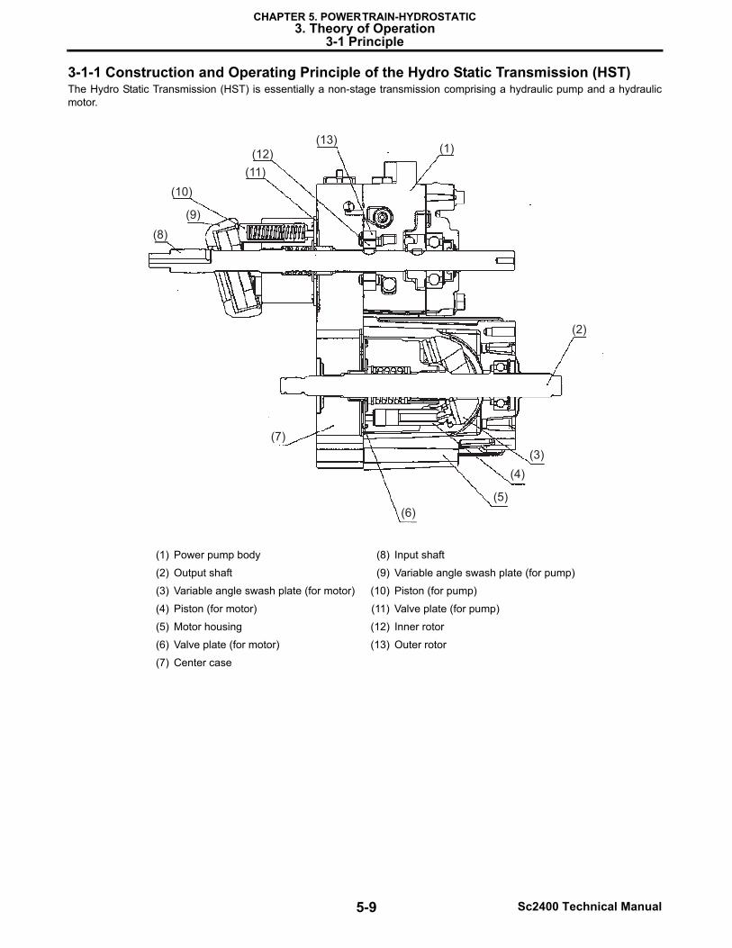
3-1-1 Construction and Operating Principle of the Hydro Static Transmission (HST)The Hydro Static Transmission (HST) is essentially a non-stage transmission comprising a hydraulic pump and a hydraulicmotor.
(1) Power pump body (8) Input shaft
(2) Output shaft (9) Variable angle swash plate (for pump)
(3) Variable angle swash plate (for motor) (10) Piston (for pump)
(4) Piston (for motor) (11) Valve plate (for pump)
(5) Motor housing (12) Inner rotor
(6) Valve plate (for motor) (13) Outer rotor
(7) Center case
(1)
(2)
(3)
(4)
(5)
(6)
(7)
(8)
(9)
(10)
(11)
(12)
(13)
5-10Sc2400 Technical Manual
CHAPTER 5. POWER TRAIN-HYDROSTATIC3. Theory of Operation
3-1 Principle
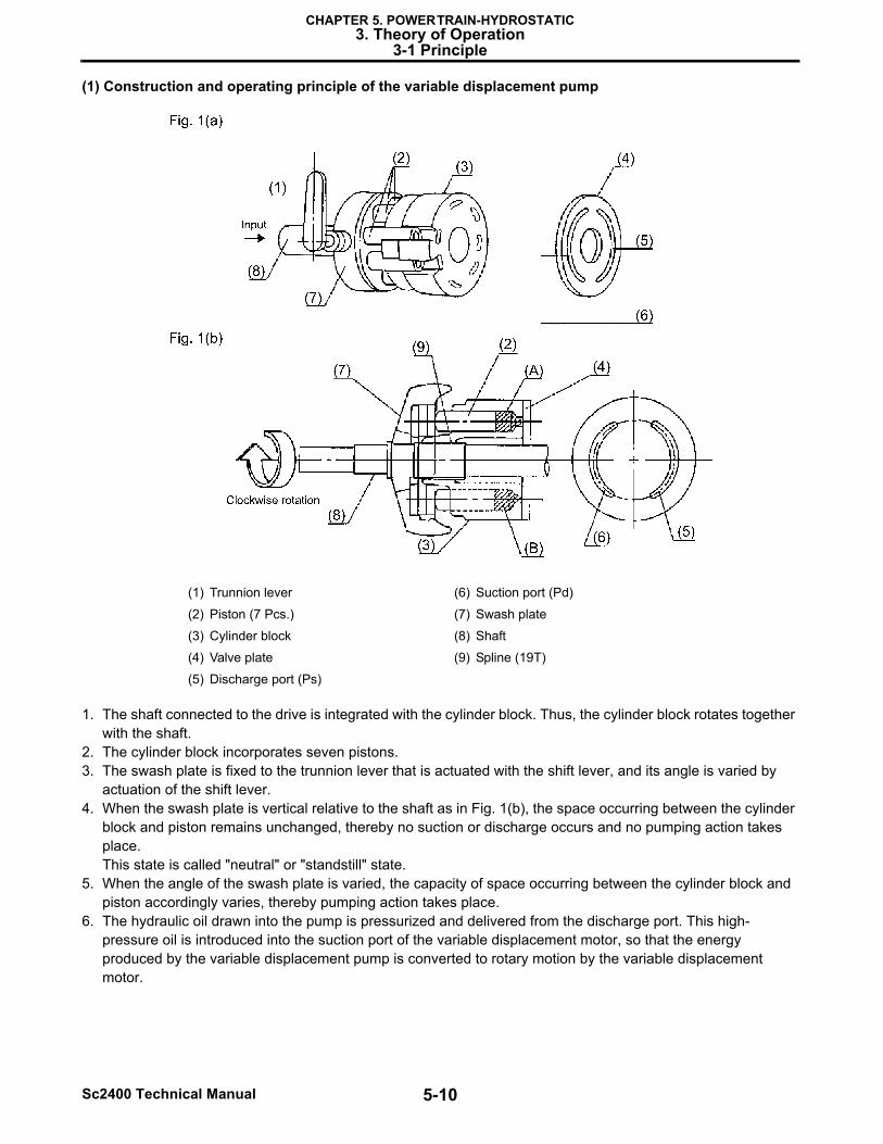
(1) Construction and operating principle of the variable displacement pump
1. The shaft connected to the drive is integrated with the cylinder block. Thus, the cylinder block rotates together with the shaft.
2. The cylinder block incorporates seven pistons.3. The swash plate is fixed to the trunnion lever that is actuated with the shift lever, and its angle is varied by
actuation of the shift lever.4. When the swash plate is vertical relative to the shaft as in Fig. 1(b), the space occurring between the cylinder
block and piston remains unchanged, thereby no suction or discharge occurs and no pumping action takes place.This state is called "neutral" or "standstill" state.
5. When the angle of the swash plate is varied, the capacity of space occurring between the cylinder block and piston accordingly varies, thereby pumping action takes place.
6. The hydraulic oil drawn into the pump is pressurized and delivered from the discharge port. This high-pressure oil is introduced into the suction port of the variable displacement motor, so that the energy produced by the variable displacement pump is converted to rotary motion by the variable displacement motor.
(1) Trunnion lever (6) Suction port (Pd)
(2) Piston (7 Pcs.) (7) Swash plate
(3) Cylinder block (8) Shaft
(4) Valve plate (9) Spline (19T)
(5) Discharge port (Ps)
5-11 Sc2400 Technical Manual
CHAPTER 5. POWER TRAIN-HYDROSTATIC3. Theory of Operation
3-1 Principle
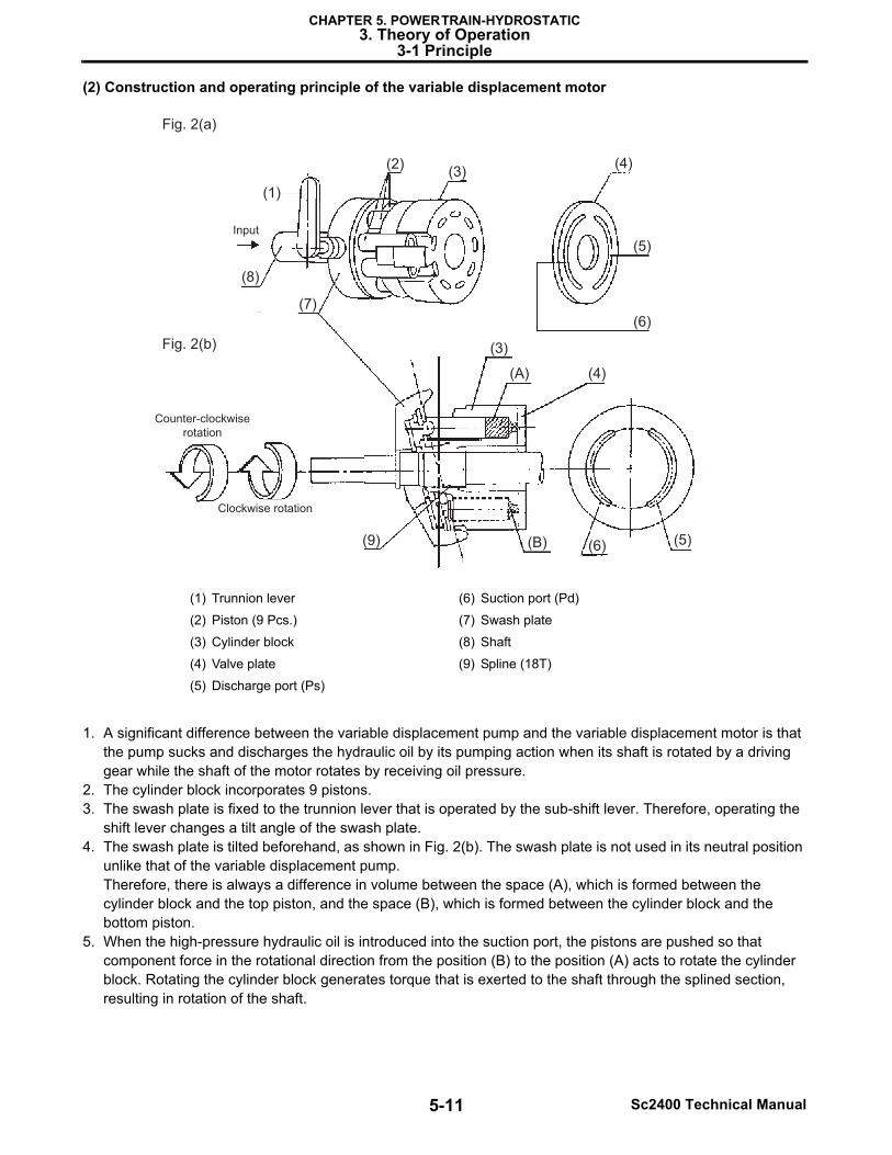
(2) Construction and operating principle of the variable displacement motor
1. A significant difference between the variable displacement pump and the variable displacement motor is that the pump sucks and discharges the hydraulic oil by its pumping action when its shaft is rotated by a driving gear while the shaft of the motor rotates by receiving oil pressure.
2. The cylinder block incorporates 9 pistons.3. The swash plate is fixed to the trunnion lever that is operated by the sub-shift lever. Therefore, operating the
shift lever changes a tilt angle of the swash plate.4. The swash plate is tilted beforehand, as shown in Fig. 2(b). The swash plate is not used in its neutral position
unlike that of the variable displacement pump.Therefore, there is always a difference in volume between the space (A), which is formed between the cylinder block and the top piston, and the space (B), which is formed between the cylinder block and the bottom piston.
5. When the high-pressure hydraulic oil is introduced into the suction port, the pistons are pushed so that component force in the rotational direction from the position (B) to the position (A) acts to rotate the cylinder block. Rotating the cylinder block generates torque that is exerted to the shaft through the splined section, resulting in rotation of the shaft.
(1) Trunnion lever (6) Suction port (Pd)
(2) Piston (9 Pcs.) (7) Swash plate
(3) Cylinder block (8) Shaft
(4) Valve plate (9) Spline (18T)
(5) Discharge port (Ps)
Fig. 2(a)
Input
Counter-clockwise
rotation
Clockwise rotation
Fig. 2(b)
(1)
(2)(3)
(3)
(4)
(4)
(5)
(5)
(6)
(6)
(7)
(A)
(B)
(8)
(9)
5-12Sc2400 Technical Manual
CHAPTER 5. POWER TRAIN-HYDROSTATIC3. Theory of Operation
3-1 Principle
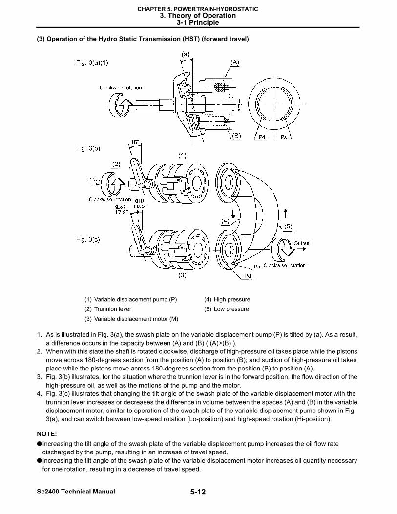
(3) Operation of the Hydro Static Transmission (HST) (forward travel)
1. As is illustrated in Fig. 3(a), the swash plate on the variable displacement pump (P) is tilted by (a). As a result, a difference occurs in the capacity between (A) and (B) ( (A)>(B) ).
2. When with this state the shaft is rotated clockwise, discharge of high-pressure oil takes place while the pistons move across 180-degrees section from the position (A) to position (B); and suction of high-pressure oil takes place while the pistons move across 180-degrees section from the position (B) to position (A).
3. Fig. 3(b) illustrates, for the situation where the trunnion lever is in the forward position, the flow direction of the high-pressure oil, as well as the motions of the pump and the motor.
4. Fig. 3(c) illustrates that changing the tilt angle of the swash plate of the variable displacement motor with the trunnion lever increases or decreases the difference in volume between the spaces (A) and (B) in the variable displacement motor, similar to operation of the swash plate of the variable displacement pump shown in Fig. 3(a), and can switch between low-speed rotation (Lo-position) and high-speed rotation (Hi-position).
NOTE:●Increasing the tilt angle of the swash plate of the variable displacement pump increases the oil flow rate
discharged by the pump, resulting in an increase of travel speed.●Increasing the tilt angle of the swash plate of the variable displacement motor increases oil quantity necessary
for one rotation, resulting in a decrease of travel speed.
(1) Variable displacement pump (P) (4) High pressure
(2) Trunnion lever (5) Low pressure
(3) Variable displacement motor (M)
5-13 Sc2400 Technical Manual
CHAPTER 5. POWER TRAIN-HYDROSTATIC3. Theory of Operation
3-1 Principle
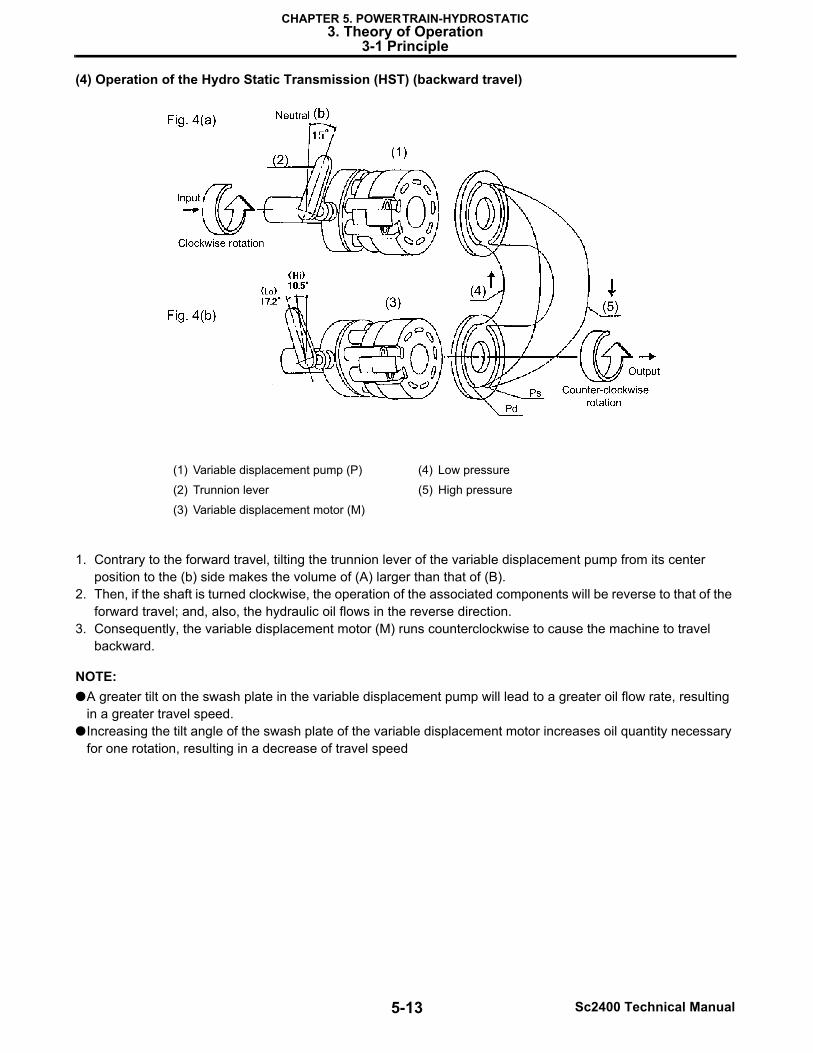
(4) Operation of the Hydro Static Transmission (HST) (backward travel)
1. Contrary to the forward travel, tilting the trunnion lever of the variable displacement pump from its center position to the (b) side makes the volume of (A) larger than that of (B).
2. Then, if the shaft is turned clockwise, the operation of the associated components will be reverse to that of the forward travel; and, also, the hydraulic oil flows in the reverse direction.
3. Consequently, the variable displacement motor (M) runs counterclockwise to cause the machine to travel backward.
NOTE:●A greater tilt on the swash plate in the variable displacement pump will lead to a greater oil flow rate, resulting
in a greater travel speed.●Increasing the tilt angle of the swash plate of the variable displacement motor increases oil quantity necessary
for one rotation, resulting in a decrease of travel speed
(1) Variable displacement pump (P) (4) Low pressure
(2) Trunnion lever (5) High pressure
(3) Variable displacement motor (M)
5-14Sc2400 Technical Manual
CHAPTER 5. POWER TRAIN-HYDROSTATIC3. Theory of Operation
3-1 Principle
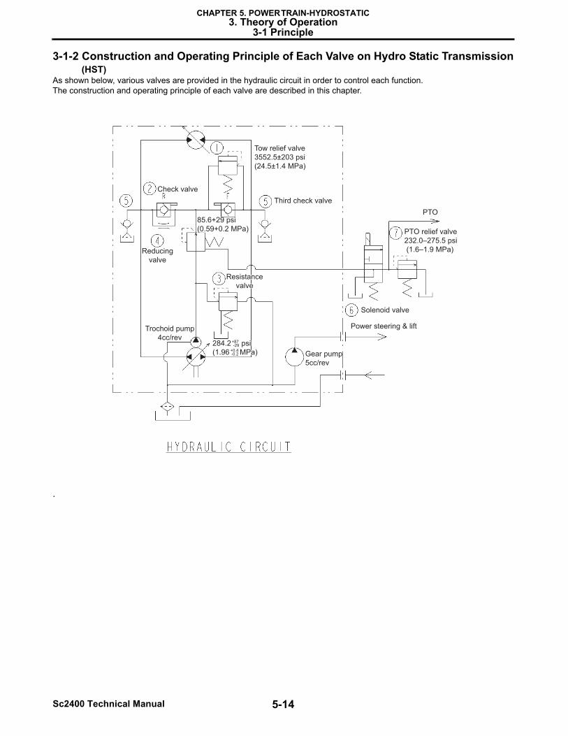
3-1-2 Construction and Operating Principle of Each Valve on Hydro Static Transmission (HST)
As shown below, various valves are provided in the hydraulic circuit in order to control each function.The construction and operating principle of each valve are described in this chapter.
.
Tow relief valve
3552.5±203 psi
(24.5±1.4 MPa)
Third check valve
PTO
PTO relief valve
232.0–275.5 psi
(1.6–1.9 MPa)
Solenoid valve
Power steering & lift
Gear pump
5cc/rev
284.2 psi
(1.96 MPa)
284.2 psi
(1.96 MPa)
+87-29
+0.4-0.2
Trochoid pump
4cc/rev
85.6+29 psi
(0.59+0.2 MPa)
Reducing
valve
Resistance
valve
Resistance
valve
Check valve
5-15 Sc2400 Technical Manual
CHAPTER 5. POWER TRAIN-HYDROSTATIC3. Theory of Operation
3-1 Principle
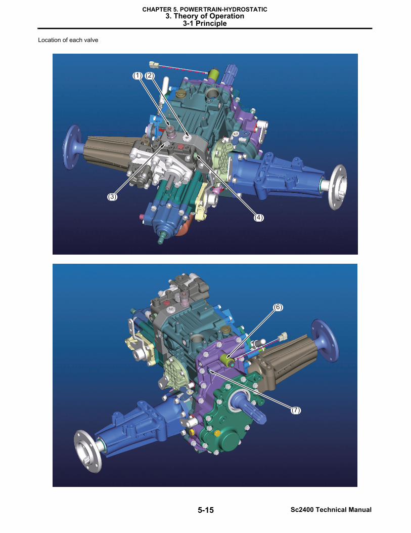
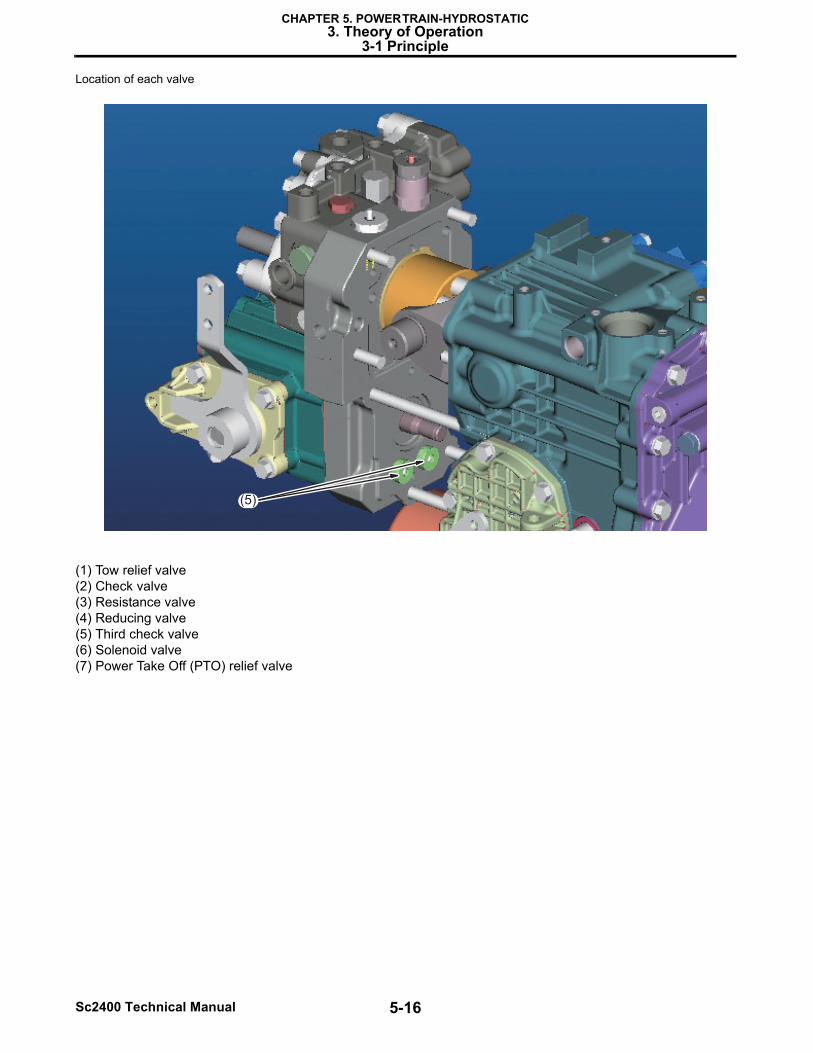
Location of each valve
(2)(1)
(3)
(4)
(6)
(7)
5-16Sc2400 Technical Manual
CHAPTER 5. POWER TRAIN-HYDROSTATIC3. Theory of Operation
3-1 Principle
Location of each valve
(1) Tow relief valve(2) Check valve(3) Resistance valve(4) Reducing valve(5) Third check valve(6) Solenoid valve(7) Power Take Off (PTO) relief valve
(5)
5-17 Sc2400 Technical Manual
CHAPTER 5. POWER TRAIN-HYDROSTATIC3. Theory of Operation
3-1 Principle
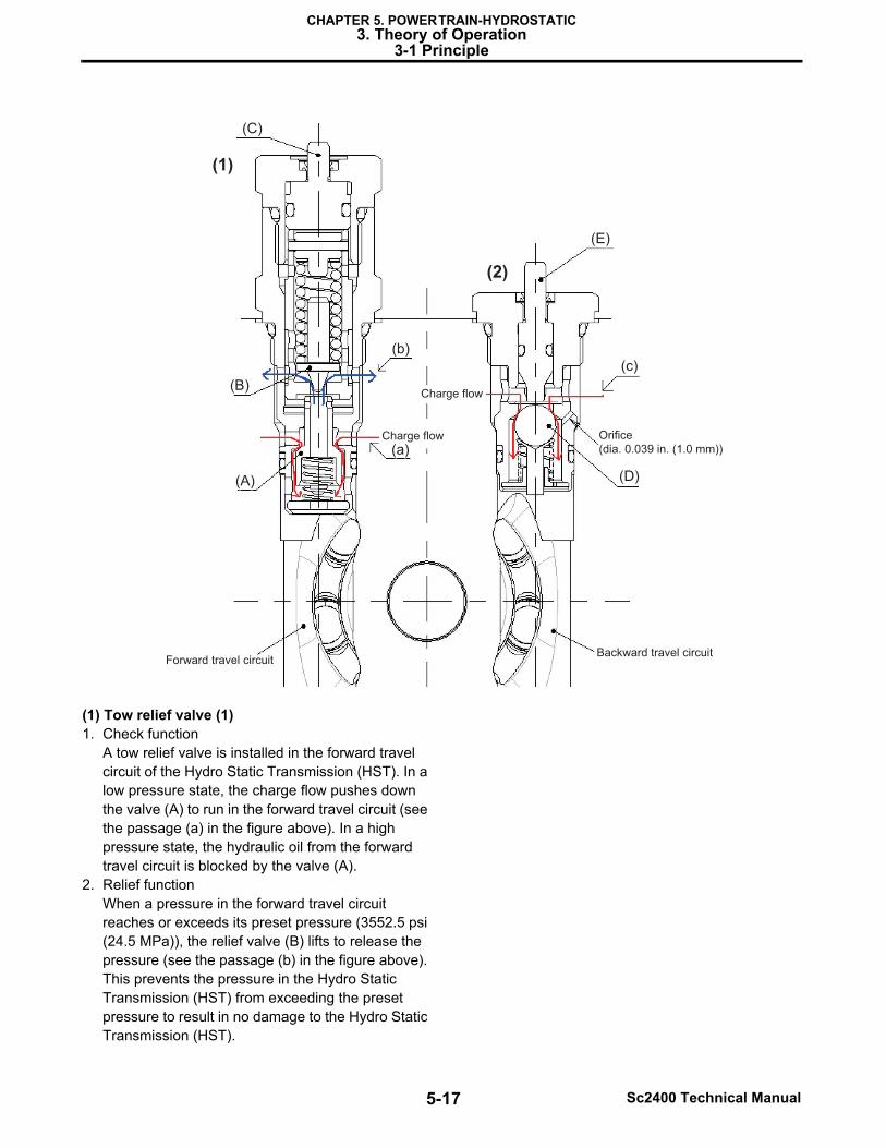
(1) Tow relief valve (1)1. Check function
A tow relief valve is installed in the forward travel circuit of the Hydro Static Transmission (HST). In a low pressure state, the charge flow pushes down the valve (A) to run in the forward travel circuit (see the passage (a) in the figure above). In a high pressure state, the hydraulic oil from the forward travel circuit is blocked by the valve (A).
2. Relief functionWhen a pressure in the forward travel circuit reaches or exceeds its preset pressure (3552.5 psi (24.5 MPa)), the relief valve (B) lifts to release the pressure (see the passage (b) in the figure above). This prevents the pressure in the Hydro Static Transmission (HST) from exceeding the preset pressure to result in no damage to the Hydro Static Transmission (HST).
Charge flow
Charge flow
Forward travel circuitBackward travel circuit
Orifice
(dia. 0.039 in. (1.0 mm))
(C)
(E)
(B)
(A) (D)
(c)(b)
(a)
(1)
(2)
5-18Sc2400 Technical Manual
CHAPTER 5. POWER TRAIN-HYDROSTATIC3. Theory of Operation
3-1 Principle
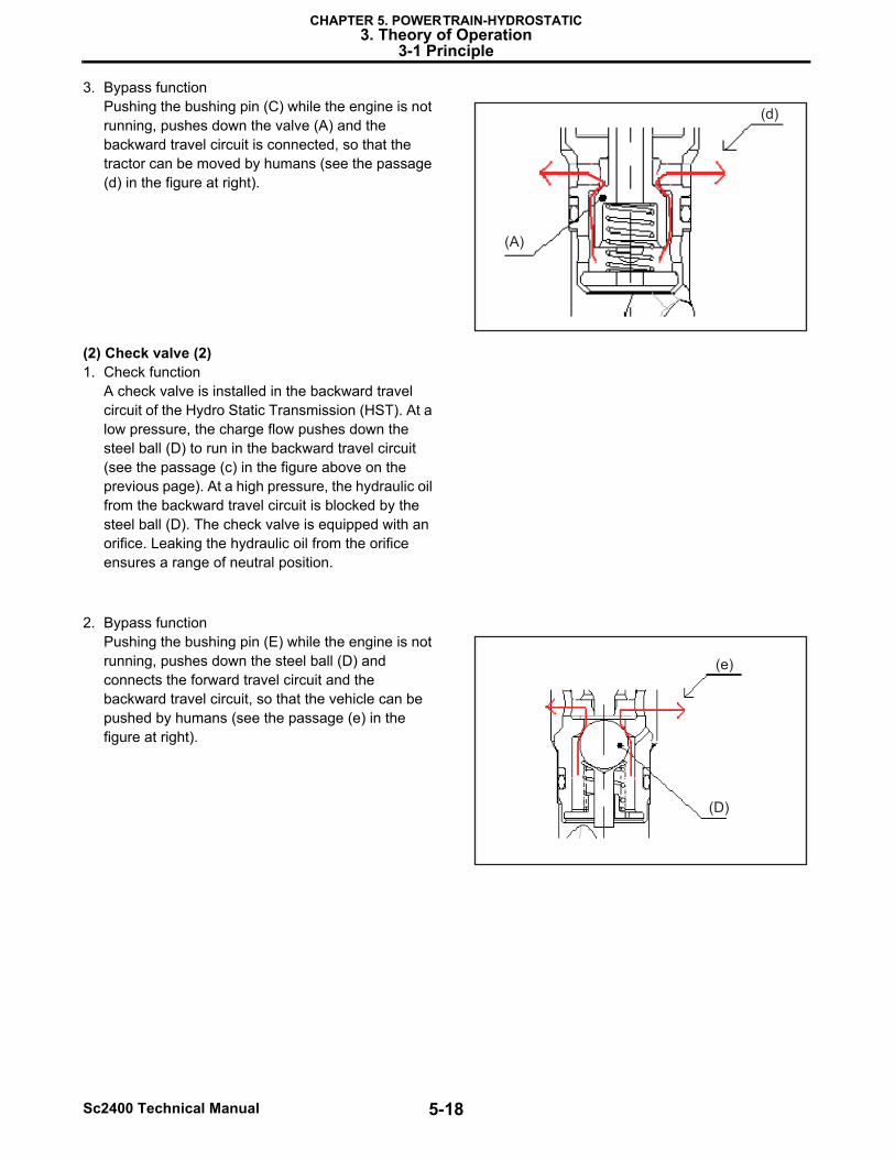
3. Bypass functionPushing the bushing pin (C) while the engine is not running, pushes down the valve (A) and the backward travel circuit is connected, so that the tractor can be moved by humans (see the passage (d) in the figure at right).
(2) Check valve (2)1. Check function
A check valve is installed in the backward travel circuit of the Hydro Static Transmission (HST). At a low pressure, the charge flow pushes down the steel ball (D) to run in the backward travel circuit (see the passage (c) in the figure above on the previous page). At a high pressure, the hydraulic oil from the backward travel circuit is blocked by the steel ball (D). The check valve is equipped with an orifice. Leaking the hydraulic oil from the orifice ensures a range of neutral position.
2. Bypass functionPushing the bushing pin (E) while the engine is not running, pushes down the steel ball (D) and connects the forward travel circuit and the backward travel circuit, so that the vehicle can be pushed by humans (see the passage (e) in the figure at right).
(d)
(A)
(e)
(D)
5-19 Sc2400 Technical Manual
CHAPTER 5. POWER TRAIN-HYDROSTATIC3. Theory of Operation
3-1 Principle
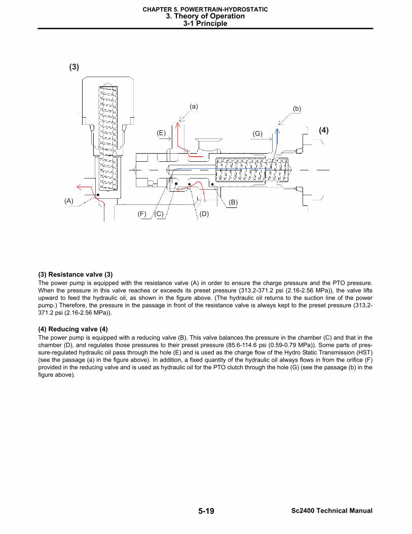
(3) Resistance valve (3)The power pump is equipped with the resistance valve (A) in order to ensure the charge pressure and the PTO pressure.When the pressure in this valve reaches or exceeds its preset pressure (313.2-371.2 psi (2.16-2.56 MPa)), the valve liftsupward to feed the hydraulic oil, as shown in the figure above. (The hydraulic oil returns to the suction line of the powerpump.) Therefore, the pressure in the passage in front of the resistance valve is always kept to the preset pressure (313.2-371.2 psi (2.16-2.56 MPa)).
(4) Reducing valve (4)The power pump is equipped with a reducing valve (B). This valve balances the pressure in the chamber (C) and that in thechamber (D), and regulates those pressures to their preset pressure (85.6-114.6 psi (0.59-0.79 MPa)). Some parts of pres-sure-regulated hydraulic oil pass through the hole (E) and is used as the charge flow of the Hydro Static Transmission (HST)(see the passage (a) in the figure above). In addition, a fixed quantity of the hydraulic oil always flows in from the orifice (F)provided in the reducing valve and is used as hydraulic oil for the PTO clutch through the hole (G) (see the passage (b) in thefigure above).
(G) (4)
(3)
(A)
(F) (C)
(E)
(a) (b)
(D)
(B)
5-20Sc2400 Technical Manual
CHAPTER 5. POWER TRAIN-HYDROSTATIC3. Theory of Operation
3-1 Principle
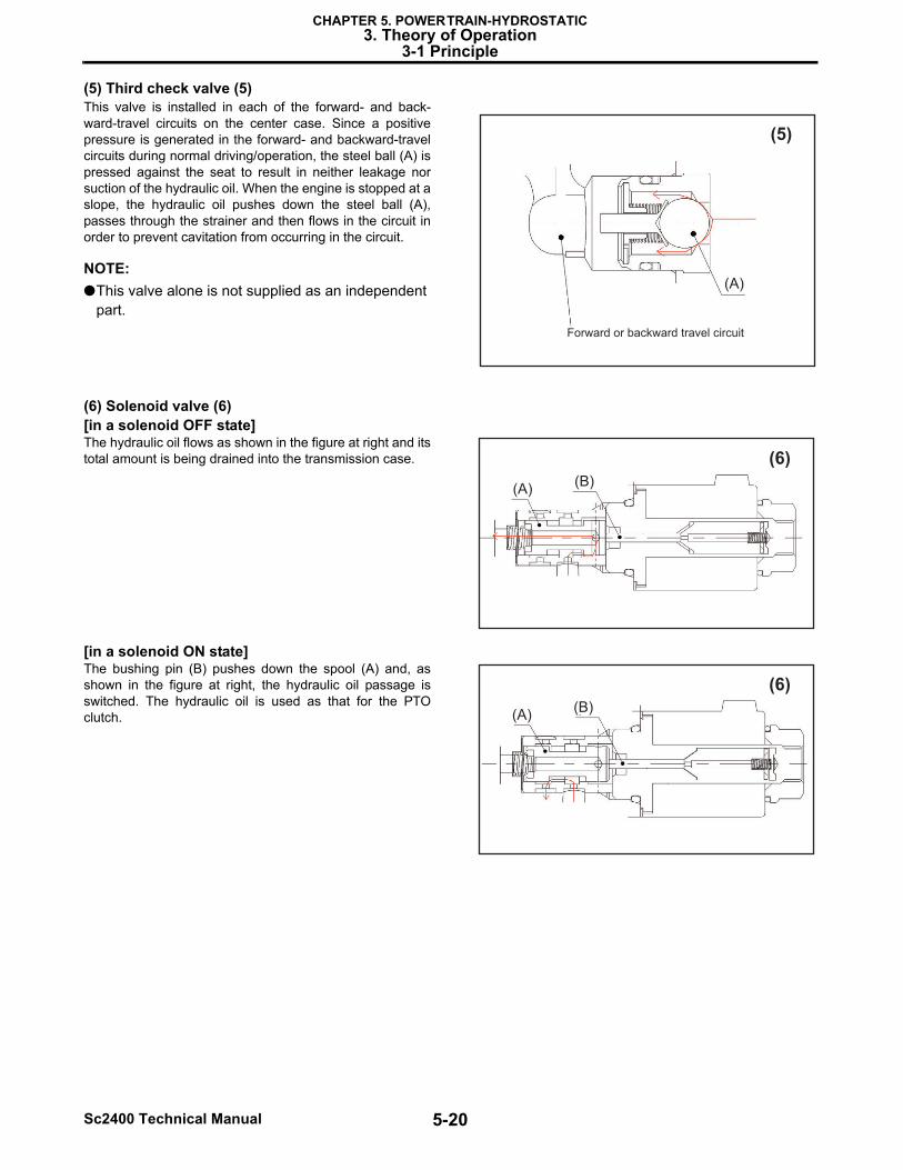
(5) Third check valve (5)This valve is installed in each of the forward- and back-ward-travel circuits on the center case. Since a positivepressure is generated in the forward- and backward-travelcircuits during normal driving/operation, the steel ball (A) ispressed against the seat to result in neither leakage norsuction of the hydraulic oil. When the engine is stopped at aslope, the hydraulic oil pushes down the steel ball (A),passes through the strainer and then flows in the circuit inorder to prevent cavitation from occurring in the circuit.
NOTE:●This valve alone is not supplied as an independent
part.
(6) Solenoid valve (6)[in a solenoid OFF state]The hydraulic oil flows as shown in the figure at right and itstotal amount is being drained into the transmission case.
[in a solenoid ON state]The bushing pin (B) pushes down the spool (A) and, asshown in the figure at right, the hydraulic oil passage isswitched. The hydraulic oil is used as that for the PTOclutch.
(5)
Forward or backward travel circuit
(A)
(6)
(A)(B)
(6)
(A)(B)
5-21 Sc2400 Technical Manual
CHAPTER 5. POWER TRAIN-HYDROSTATIC3. Theory of Operation
3-1 Principle
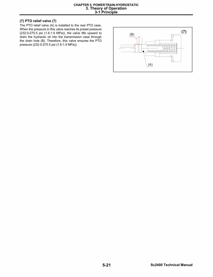
(7) PTO relief valve (7)The PTO relief valve (A) is installed to the rear PTO case.When the pressure in this valve reaches its preset pressure(232.0-275.5 psi (1.6-1.9 MPa)), the valve lifts upward todrain the hydraulic oil into the transmission case throughthe drain hole (B). Therefore, this valve ensures the PTOpressure (232.0-275.5 psi (1.6-1.9 MPa)).
(7)
(A)
(B)
5-22Sc2400 Technical Manual
CHAPTER 5. POWER TRAIN-HYDROSTATIC3. Theory of Operation
3-1 Principle
3-1-3 Transmission route of driving force(1) Power schematic
Hydro
Sta
tic T
ransm
issio
n
(H
ST
) pum
p
Hydro
Sta
tic T
ransm
issio
n
(HS
T)
moto
r
Tra
nsaxle
Clu
tch p
ack
572m
in-1
RE
AR
PT
O
SLR
: S
tatic L
oaded R
adiu
s
MF
WD
: M
echanic
al F
ront W
heel D
rive
Gear
pum
p
Engin
e
22hp@
3300m
in-1
FW
D
MID
PT
O
35T
23T
20T
19T
45T
13T
8T
65T
26”
TIR
E
(SLR
11.7
inch (
301 m
m))
14T
61T
29T
20T
39T
62T
RE
V
Bra
ke
HIG
HLO
W
MF
WD
OU
T
5-23 Sc2400 Technical Manual
CHAPTER 5. POWER TRAIN-HYDROSTATIC3. Theory of Operation
3-1 Principle
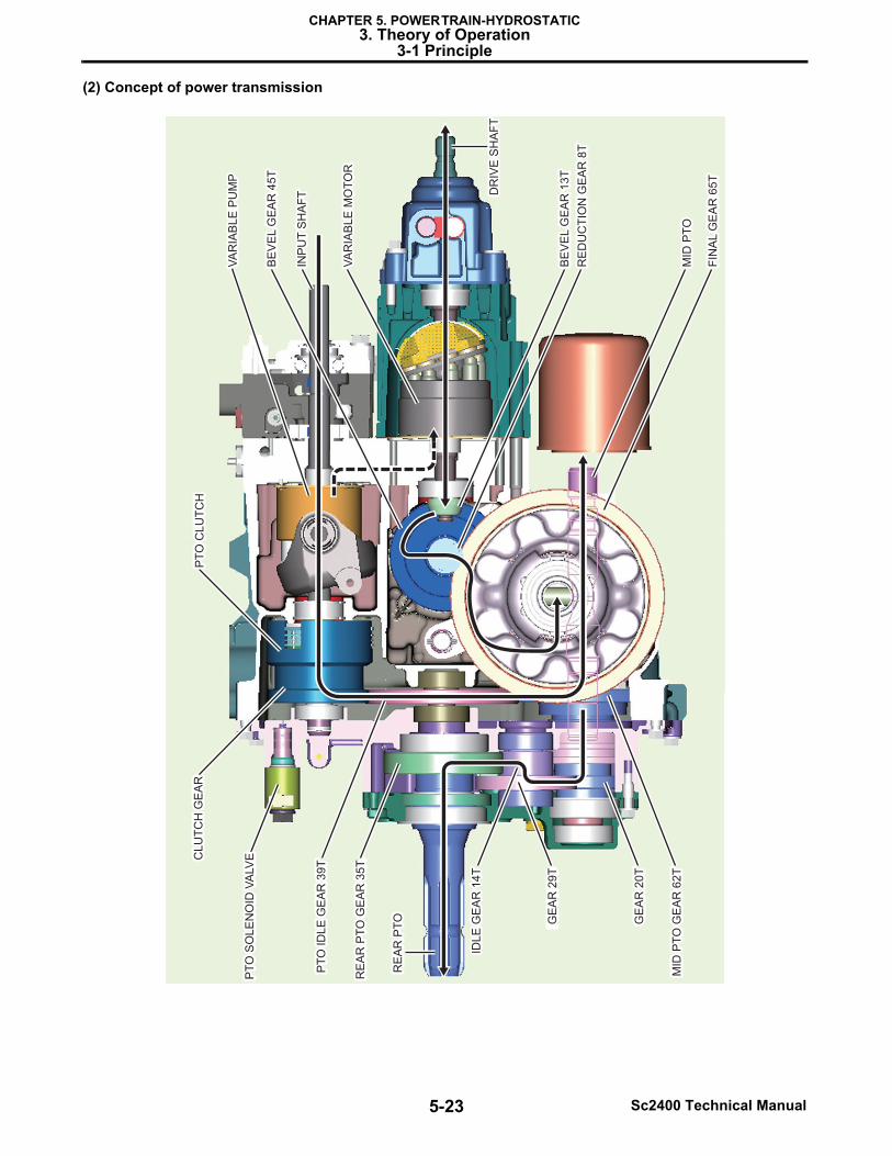
(2) Concept of power transmission
VA
RIA
BLE
PU
MP
BE
VE
L G
EA
R 4
5T
INP
UT
SH
AF
T
VA
RIA
BLE
MO
TO
R
DR
IVE
SH
AF
T
BE
VE
L G
EA
R 1
3T
RE
DU
CT
ION
GE
AR
8T
MID
PT
O
FIN
AL G
EA
R 6
5T
MID
PT
O G
EA
R 6
2T
GE
AR
20
T
RE
AR
PT
O
IDL
E G
EA
R 1
4T
RE
AR
PT
O G
EA
R 3
5A
PT
O S
OL
EN
OID
VA
LV
E
PT
O I
DL
E G
EA
R 3
9T
CL
UT
CH
GE
AR
PT
O C
LU
TC
H
VA
RIA
BLE
PU
MP
BE
VE
L G
EA
R 4
5T
INP
UT
SH
AF
T DR
IVE
SH
AF
T
BE
VE
L G
EA
R 1
3T
RE
DU
CT
ION
GE
AR
8T
MID
PT
O
FIN
AL G
EA
R 6
5T
MID
PT
O G
EA
R 6
2T
GE
AR
20
T
GE
AR
29
T
IDL
E G
EA
R 1
4T
RE
AR
PT
O G
EA
R 3
5T
PT
O S
OL
EN
OID
VA
LV
E
PT
O I
DL
E G
EA
R 3
9T
CL
UT
CH
GE
AR
PT
O C
LU
TC
H
RE
AR
PT
OR
EA
R P
TO
VA
RIA
BLE
MO
TO
R
5-24Sc2400 Technical Manual
CHAPTER 5. POWER TRAIN-HYDROSTATIC3. Theory of Operation
3-2 Releasing the Hydraulic Pressure in the Transaxle
3-2 Releasing the Hydraulic Pressure in the Transaxle*When the engine is not running!!
On the center plate, there is tow relief valve and check valve. On top of the tow relief valve and check valve, there are "By-pass push pins".
When those pins are pushed, the oil will be escaped to the transmission case through the charge circuit.
Those two pins are pushed by Hydro Static Transmission (HST) pressure plate.
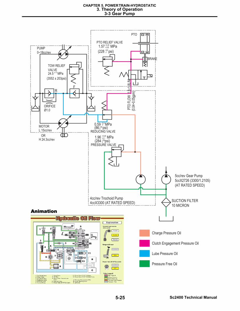
3-3 Gear PumpThere are two kinds of pump.
One that is attached with the transaxle is trochoid pump as the charge pump for Hydro Static Transmission (HST) unit.
The other is the gear pump which supplies the hydraulic pressured oil for the power steering, lift valve and loader valve.
5-25 Sc2400 Technical Manual
CHAPTER 5. POWER TRAIN-HYDROSTATIC3. Theory of Operation
3-3 Gear Pump
PUMP
0~18cc/rev
ORIFICEØ1.0
MOTORL 15cc/rev
ORH 24.3cc/rev
PTO
BRAKE
MPa+0.29-0.051.57
psi)+42-7(228
PTO RELIEF VALVE
MPa+0.2
+290
00.59(86 psi)
+290(284 psi)
REDUCING VALVEPT
O F
LOW
1.5
~1.8
L/M
(0.0
4~0.
05gp
m)
SUCTION FILTER10 MICRON
Charge Pressure Oil
Clutch Engagement Pressure Oil
Lube Pressure Oil
Pressure Free Oil
RF
TOW RELIEF
VALVEMPa±1.424.5
(3552 ± 203psi)
4cc/rev Trochoid Pump
MPa+0.45+0.11.96
PRESSURE VALVE
5cc/rev Gear Pump5ccX2726 (3300/1.2105)(AT RATED SPEED)
4ccX3300 (AT RATED SPEED)
Animation