Embed Size (px)
Citation preview

Training courses that PSMi can offer to the
customers:
Trainer: Viktor P. Astakhov is the Tool Research and Application Manager of PSMi

PSMi Courses
This has been gradually changing in manufacturing since the beginning of the 21st century. To
address these issues, leading tool and machine manufacturers have developed a number of new
products—new tool materials and coatings, new cutting inserts and tool designs, and other
aspects of machining in order to increase the efficiency of machining operations in industry by
increasing working speeds, feed rates, tool life, and reliability. Today, it is common to use dry
hobbing with high-speed steel hobs at 80 m/min. Modern grades of polycrystalline diamond
(PCD) tool material allow milling, drilling, and reaming of high-silicon aluminum alloys at
speeds of 1,000-8,000 m/min. Modern grades of carbide tools combined with advanced coatings
allow machining of alloyed steels at speeds of 300-600 m/min.
Nowadays, machines with great ranges of speed and feed and high-precision spindles, high-
pressure coolant supplies; high-precision hydraulic and shrink-fit tool holders; tool pre-setting
machines (Zollar and Kelch, for example); advanced machine controllers; and many other
improvements have become common. In tool manufacturing system, CNC tool grinders (for
example, EWAG, Walter, Star, ANKA, etc.) and tool inspection machines (for example, Helicheck,
Zoller/genius 3) were introduced. In the tool design, three-dimensional (3D) solid modeling
software packages were introduced to help tool designers. New tool materials and advanced
grades of the existing tool materials, including nano-coatings, were introduced.
The cutting tool manufacturers were pushed to the forefront to show their capability to produce
new tools to address new challenges in metal machining – high productivity rates, low-cost
parts, great quality, suitable tool reliability, particularly for unattended manufacturing lines and
cells. In light of the trainer’s experience, they, together with all metal cutting-related academics
and researchers, failed miserably to meet this goal. The root cause of the failure of the tool
manufacturers is the lack of specialists capable of understanding the fundamental principles of
metal cutting and tool design as well as tool application aspects.
PSMi offers a unique set of courses on machining because:
1. PSMi has a unique experience managing cutting tools for various industries (e.g.,
automotive, medical, aerospace). Being directly responsible for efficiency, quality and
reliability of machining operations, PSMi gained a unique combination of knowledge on
tool performance, tool design, tool materials, etc.
2. PSMi specialists combine knowledge and experience from academia and industry.
3. PSMi is not a tool manufactures so it acts as an independent tool quality evaluator.
However, PSMi develops its own tool designs correcting drawbacks of cutting tools.
4. PSMi involves in research and development activities on metal cutting and cutting tools.
5. PSMi involves in publishing of great variety of materials including academic books and
monographs, journal papers and articles, reference materials, manuals, industrial
reports, etc.
No one other tool commodity management company or even a tool manufacturing
company possesses such a unique experience.
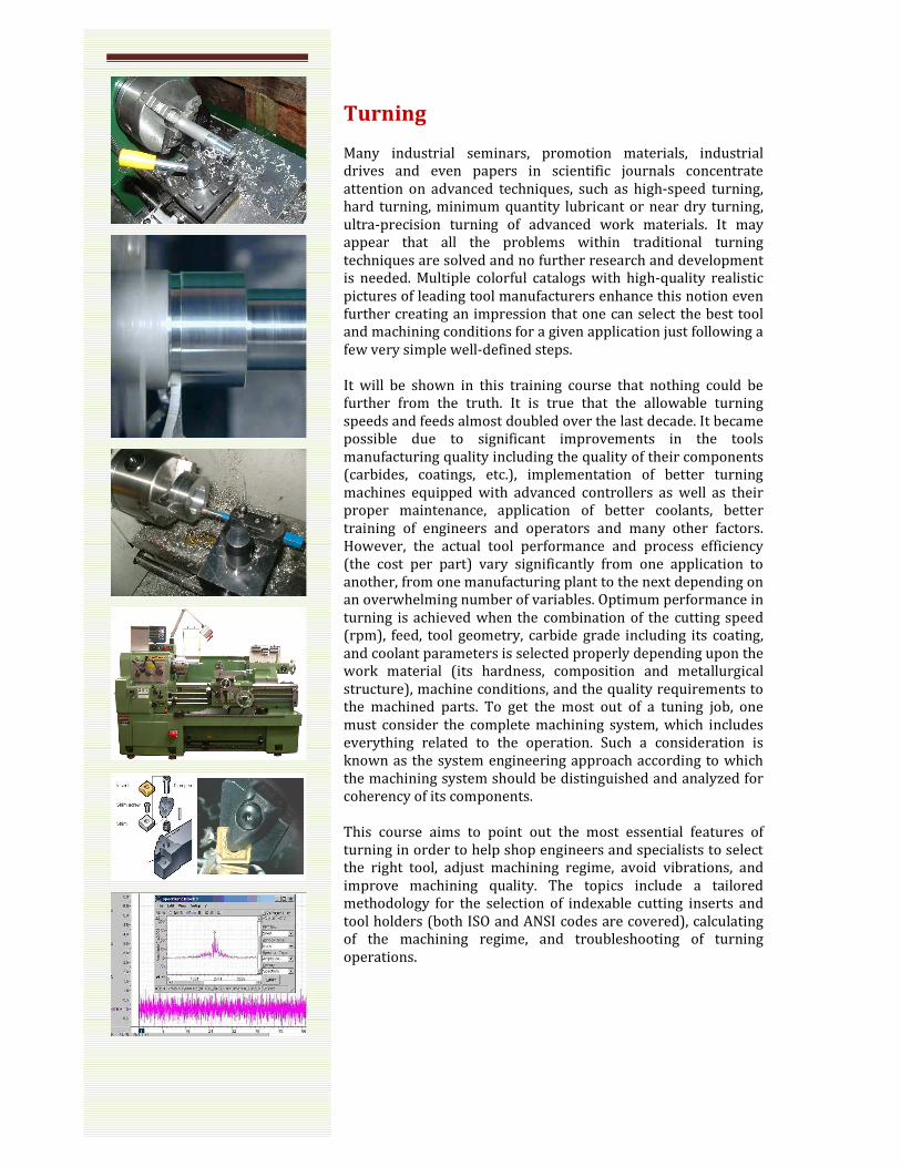
Turning
Many industrial seminars, promotion materials, industrial
drives and even papers in scientific journals concentrate
attention on advanced techniques, such as high-speed turning,
hard turning, minimum quantity lubricant or near dry turning,
ultra-precision turning of advanced work materials. It may
appear that all the problems within traditional turning
techniques are solved and no further research and development
is needed. Multiple colorful catalogs with high-quality realistic
pictures of leading tool manufacturers enhance this notion even
further creating an impression that one can select the best tool
and machining conditions for a given application just following a
few very simple well-defined steps.
It will be shown in this training course that nothing could be
further from the truth. It is true that the allowable turning
speeds and feeds almost doubled over the last decade. It became
possible due to significant improvements in the tools
manufacturing quality including the quality of their components
(carbides, coatings, etc.), implementation of better turning
machines equipped with advanced controllers as well as their
proper maintenance, application of better coolants, better
training of engineers and operators and many other factors.
However, the actual tool performance and process efficiency
(the cost per part) vary significantly from one application to
another, from one manufacturing plant to the next depending on
an overwhelming number of variables. Optimum performance in
turning is achieved when the combination of the cutting speed
(rpm), feed, tool geometry, carbide grade including its coating,
and coolant parameters is selected properly depending upon the
work material (its hardness, composition and metallurgical
structure), machine conditions, and the quality requirements to
the machined parts. To get the most out of a tuning job, one
must consider the complete machining system, which includes
everything related to the operation. Such a consideration is
known as the system engineering approach according to which
the machining system should be distinguished and analyzed for
coherency of its components.
This course aims to point out the most essential features of
turning in order to help shop engineers and specialists to select
the right tool, adjust machining regime, avoid vibrations, and
improve machining quality. The topics include a tailored
methodology for the selection of indexable cutting inserts and
tool holders (both ISO and ANSI codes are covered), calculating
of the machining regime, and troubleshooting of turning
operations.

2. Drilling
2.1 Basic level
Various studies and surveys indicate that holemaking (drilling)
is one of the most time-consuming metal cutting operations in
the typical shop. It is estimated that 36% of all machine hours
(40% of CNC) are spent performing holemaking operations, as
opposed to 25% for turning and 26% for milling, producing
60% of chips. Therefore, the use of high-performance drills and
reamers could significantly reduce the time required for drilling
operations, and thus reduce holemaking costs.
Over the past decade, the tool materials and coatings used for
drills have improved dramatically. Combined with new
powerful, high-speed-spindles rigid machines, proper tooling
including tool and work holding, and high-pressure high-
concentration coolant supply, these allowed a significant
increase in the cutting speed and penetration rate in drilling
operations. In modern machine shops, as, for example, in the
automotive industry, quality requirement to drilled holes today
are the same as they used to be for reamed holes a decade ago.
Despite all the new developments in drilling, however, there is
still a significant gap in efficiency, quality and reliability of
drilling operation between advanced and common machine
shops. This gap is due to lack of understanding the process and
its surrounding. Therefore, the objective of this course is two-
fold. First, it aims to familiarize application specialists with
properly-defined basic concepts, terminology, and essentials of
drilling. Second, it introduces the concept of the drilling system
formulating the systems rules (laws) and showing the impact of
the first-level system components. The course includes topics on
the selection of application-specific tools, requirements to their
drawings and inspection, tool setting practice, and
troubleshooting of drilling operations.
DR
ILL
ING
CO
RE
DR
ILL
ING
ST
EP
DR
ILL
ING
CO
UN
TE
RB
OR
ING
CO
UT
ER
SIN
KIN
G
RE
AM
ING
CE
NT
ER
DR
ILLI
NG
GU
ND
RIL
LIN
G
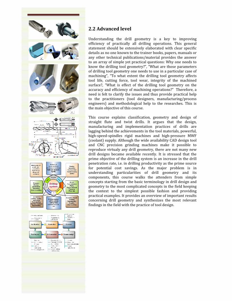
2.2 Advanced level
Understanding the drill geometry is a key to improving
efficiency of practically all drilling operations. This general
statement should be extensively elaborated with clear specific
details as no one known to the trainer books, papers, manuals or
any other technical publications/material provides the answer
to an array of simple yet practical questions: Why one needs to
know the drilling tool geometry?”, “What are those parameters
of drilling tool geometry one needs to use in a particular case of
machining”, “To what extent the drilling tool geometry affects
tool life, cutting force, tool wear, integrity of the machined
surface?, “What is effect of the drilling tool geometry on the
accuracy and efficiency of machining operations?” Therefore, a
need is felt to clarify the issues and thus provide practical help
to the practitioners (tool designers, manufacturing/process
engineers) and methodological help to the researches. This is
the main objective of this course.
This course explains classification, geometry and design of
straight flute and twist drills. It argues that the design,
manufacturing and implementation practices of drills are
lagging behind the achievements in the tool materials, powerful,
high-speed-spindles rigid machines and high-pressure MWF
(coolant) supply. Although the wide availability CAD design tool
and CNC precision grinding machines make it possible to
reproduce virtualy any drill geometry, there are not many new
drill designs became available recently. It is stressed that the
prime objective of the drilling system is an increase in the drill
penetration rate, i.e. in drilling productivity as the prime source
for potential cost savings. As the major problem is in
understanding particularities of drill geometry and its
components, this course walks the attenders from simple
concepts starting from the basic terminology in drill design and
geometry to the most complicated concepts in the field keeping
the context to the simplest possible fashion and providing
practical examples. It provides an overview of important results
concerning drill geometry and synthesizes the most relevant
findings in the field with the practice of tool design.

Tool wear
In metal cutting, tool wear is a dominant concern because
process conditions are chosen to give maximum productivity or
economy, often resulting in tool life in minutes. Central to the
problem are: high contact temperatures at the tool–chip and
tool–workpiece interfaces that lead to the softening of tool
material and promote diffusion and chemical (oxidation) wear;
high contact pressures at these interfaces and sliding of freshly
formed (juvenile) surfaces of the work material layers promote
abrasive and adhesion wear; cyclic nature of the chip formation
process which can cause cracking due to thermal fatigue.
Another tool wear mechanism is fretting wear. Fretting is a
small amplitude oscillatory motion, usually tangential, between
two solid surfaces in contact. Fretting wear occurs when
repeated loading and unloading cause cyclic stresses, which
induce surface or subsurface breakup and loss of material.
Vibration is a common cause of fretting wear. The mentioned
wear mechanisms may take place alone or, more frequently, in
combination.
The nature of tool wear, unfortunately, is not yet clear enough in
spite of numerous investigations carried out over the last 50
years. Although various theories have been introduced hitherto
to explain the wear mechanism, the complicity of the processes
in the cutting zone hampers formulation of a sound theory of
cutting tool wear.
The course consists of two parts. The first part aims to
familiarize the attendants with the standard way to
assess/measure/evaluate tool wear in accordance with
ANSI/ASME Tool Life Testing with Single-Point Turning Tools
(B94.55M-1985) Standard. The principal types of tool wear,
classified according to the regions of the tool they affect. Metrics
of too wear and their practical correlation with the work
material type/properties and machining parameters are
discussed with multiple examples carefully tailored for different
types of cutting tools: single-point turning tools, drill and
reamers, milling tools, etc. Wear curves construction and the
concept of tool life are explained.
The second logical part of the course deals with advanced
concepts of cutting tool wear assessment. The concepts of
volumetric/mass tool wear, dimension wear rate, surface wear
rate, etc. will be introduced and explained. The optimal cutting
temperature/cutting speed – the First Metal Cutting Law – will
be introduced and explained with multiple practical examples
related to various machining operations. Practical methods of
determining the optimal cutting temperature/speed are
presented in this part. The concept and practical
implementation of the cutting tool technical resource concludes
the course.
Tool materials
why
Introductio
coating
ongoing activity
th
suggested
titanium alloy, there are more than fifty tool
on the tool market supplied by a
w
Selecting the appropriate cutting tool material for a specific
application is crucial in achieving efficient
operations.
selection of the proper tool material
correlation
this course.
The course discusses various
from high carbon steel to ceramics and diamonds,
today’s metalworking industry. It
differe
differences are, and
of material.
Th
for various application
single material
needed
example increasing hardness generally results in lower
toughness.
The
of the proper
based upon
the
selection governed by material availability and economic
considerations.
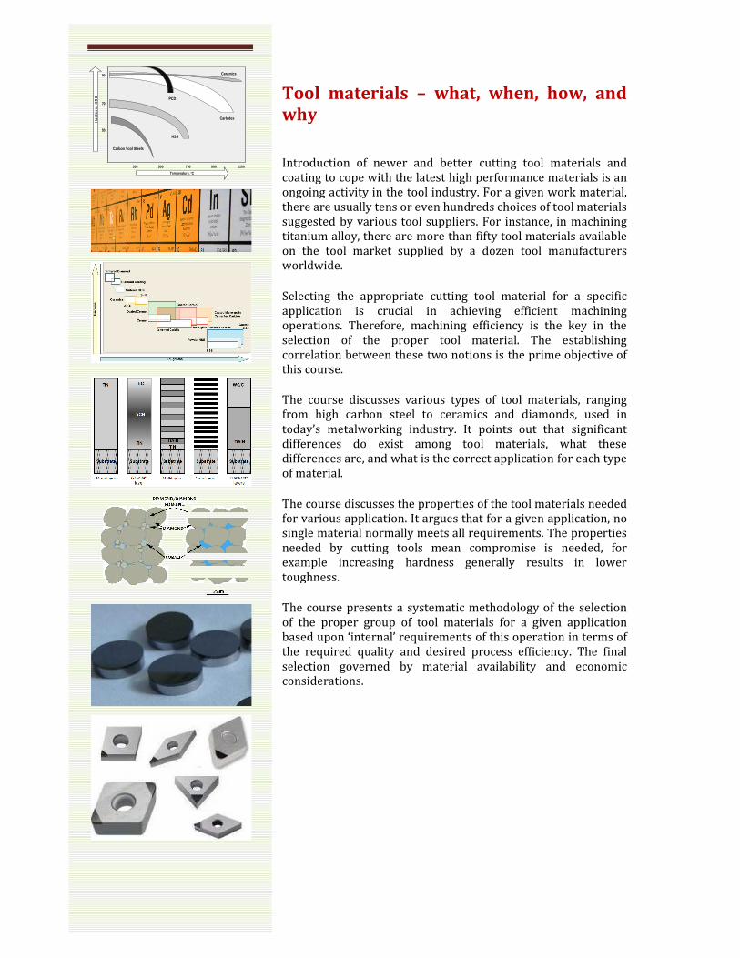
50
300 500 700 900 1100
70
90
Temperature, oC
Har
dn
ess
HR
C
Carbon Tool Steels
HSS
Carbides
PCD
Ceramics
Tool materials – what, when, how
why
Introduction of newer and better cutting tool materials
coating to cope with the latest high performance materials
ongoing activity in the tool industry. For a given work
there are usually tens or even hundreds choices of tool materials
suggested by various tool suppliers. For instance, in machining
titanium alloy, there are more than fifty tool materials available
on the tool market supplied by a dozen tool manufacturers
worldwide.
Selecting the appropriate cutting tool material for a specific
application is crucial in achieving efficient
operations. Therefore, machining efficiency is the key in the
selection of the proper tool material. The
correlation between these two notions is the prime
this course.
he course discusses various types of tool material
from high carbon steel to ceramics and diamonds,
today’s metalworking industry. It points out that
differences do exist among tool materials, what these
differences are, and what is the correct application for each type
of material.
The course discusses the properties of the tool materials
for various application. It argues that for a given application, n
single material normally meets all requirements. The properties
needed by cutting tools mean compromise is needed, for
example increasing hardness generally results in lower
toughness.
The course presents a systematic methodology of the selection
of the proper group of tool materials for a given application
based upon ‘internal’ requirements of this operation in terms of
the required quality and desired process efficiency
selection governed by material availability and economic
considerations.
how, and
newer and better cutting tool materials and
cope with the latest high performance materials is an
work material,
tens or even hundreds choices of tool materials
by various tool suppliers. For instance, in machining
materials available
manufacturers
Selecting the appropriate cutting tool material for a specific
application is crucial in achieving efficient machining
refore, machining efficiency is the key in the
The establishing
is the prime objective of
tool materials, ranging
from high carbon steel to ceramics and diamonds, used in
points out that significant
, what these
the correct application for each type
materials needed
It argues that for a given application, no
meets all requirements. The properties
by cutting tools mean compromise is needed, for
example increasing hardness generally results in lower
presents a systematic methodology of the selection
a given application
of this operation in terms of
efficiency. The final
selection governed by material availability and economic
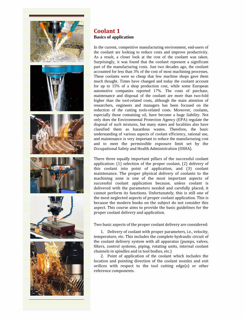
Coolant 1 Basics of application In the current, competitive manufacturing environment, end-users of the coolant are looking to reduce costs and improve productivity. As a result, a closer look at the cost of the coolant was taken. Surprisingly, it was found that the coolant represent a significant part of the manufacturing costs. Just two decades ago, the coolant accounted for less than 3% of the cost of most machining processes. These coolants were so cheap that few machine shops gave them much thought. Times have changed and today the coolant account for up to 15% of a shop production cost, while some European automotive companies reported 17%. The costs of purchase, maintenance and disposal of the coolant are more than two-fold higher than the tool-related costs, although the main attention of researchers, engineers and managers has been focused on the reduction of the cutting tools-related costs. Moreover, coolants, especially those containing oil, have become a huge liability. Not only does the Environmental Protection Agency (EPA) regulate the disposal of such mixtures, but many states and localities also have classified them as hazardous wastes. Therefore, the basic understanding of various aspects of coolant efficiency, rational use, and maintenance is very important to reduce the manufacturing cost and to meet the permissible exposure limit set by the
Occupational Safety and Health Administration (OSHA).
There three equally important pillars of the successful coolant
application: (1) selection of the proper coolant, (2) delivery of
this coolant into point of application, and (3) coolant
maintenance. The proper physical delivery of coolants to the
machining zone is one of the most important aspects of
successful coolant application because, unless coolant is
delivered with the parameters needed and carefully placed, it
cannot perform its functions. Unfortunately, this is still one of
the most neglected aspects of proper coolant application. This is
because the modern books on the subject do not consider this
aspect. This course aims to provide the basic guidelines for the
proper coolant delivery and application.
Two basic aspects of the proper coolant delivery are considered:
1. Delivery of coolant with proper parameters, i.e., velocity,
temperature, etc. This includes the complete hydraulic circuit of
the coolant delivery system with all apparatus (pumps, valves,
filters, control systems, piping, rotating units, internal coolant
channels in spindles and in tool bodies, etc.) 2. Point of application of the coolant which includes the
location and pointing direction of the coolant nozzles and exit
orifices with respect to the tool cutting edge(s) or other
reference components.
Coolant 2 High
a. This aim of the
foundations and detailed explanations of high
application techniques in metal cutting. Covering the external
(single
applications, it
flow rather not its pressure defines the efficiency of high
pre
example, the
considered in the design of hole
high
The costs of maintaining and eventually disposi
combined with the health and safety concerns, have led to a
heightened interest in either eliminating the coolant altogether
or limiting the amount of the coolant applied. The former
process is known as dry machining while the latter is
as near
(MQL) machining. In NDM, an air
fed onto the machining zone. Compared to dry machining, NDM
substantially enhances cutting performance in terms of
incr
parts. Th
NDM methods, discussing their advantages and drawbacks.
Analyzing the available information on the performance of NDM,
a physically
discussed in details. It considers the essential components of the
whole NDM system, arguing that a 360° vision approach is the
key to successful implementation of NDM.
Cryogenic coolants have been used in indus
cold treating applications for quite some time, but their
application in the machining industry as coolants is relatively
new. Cryogenic machining involves the application of a
cryogenic fluid in the machining process, primarily as a co
agent
to perform both conductive and convective cooling of the
machining zone or could be applied indirectly to cool the cutting
tool through conduction alone. The objective of the third pa
the course is to cover the complete area of cryogenic machining
starting from the basics and finishing with application
techniques including the tool designs and cryogenic liquid
delivery systems. Technical and cost efficiency of cryogenic
machining
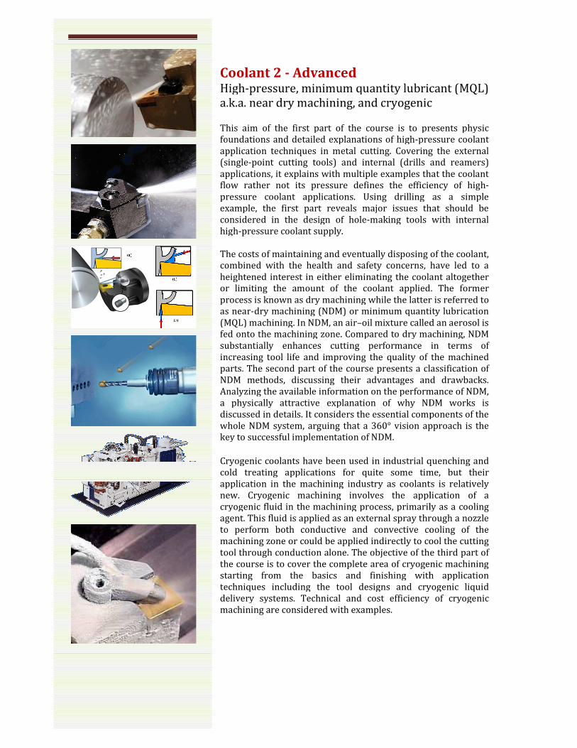
Coolant 2 - Advanced High-pressure, minimum quantity lubricant (MQL)
.k.a. near dry machining, and cryogenic
This aim of the first part of the course is to presents physic
foundations and detailed explanations of high-pressure
application techniques in metal cutting. Covering the external
(single-point cutting tools) and internal (drills and reamers)
applications, it explains with multiple examples that
flow rather not its pressure defines the efficiency of high
pressure coolant applications. Using drilling as a simple
example, the first part reveals major issues that should be
considered in the design of hole-making tools with internal
high-pressure coolant supply.
The costs of maintaining and eventually disposing of the coolant,
combined with the health and safety concerns, have led to a
heightened interest in either eliminating the coolant altogether
or limiting the amount of the coolant applied. The former
process is known as dry machining while the latter is
as near-dry machining (NDM) or minimum quantity lubrication
(MQL) machining. In NDM, an air–oil mixture called an aerosol is
fed onto the machining zone. Compared to dry machining, NDM
substantially enhances cutting performance in terms of
increasing tool life and improving the quality of the machined
parts. The second part of the course presents a classification of
NDM methods, discussing their advantages and drawbacks.
Analyzing the available information on the performance of NDM,
a physically attractive explanation of why NDM works is
discussed in details. It considers the essential components of the
whole NDM system, arguing that a 360° vision approach is the
key to successful implementation of NDM.
Cryogenic coolants have been used in industrial quenching and
cold treating applications for quite some time, but their
application in the machining industry as coolants is relatively
new. Cryogenic machining involves the application of a
cryogenic fluid in the machining process, primarily as a co
agent. This fluid is applied as an external spray through a nozzle
to perform both conductive and convective cooling of the
machining zone or could be applied indirectly to cool the cutting
tool through conduction alone. The objective of the third pa
the course is to cover the complete area of cryogenic machining
starting from the basics and finishing with application
techniques including the tool designs and cryogenic liquid
delivery systems. Technical and cost efficiency of cryogenic
machining are considered with examples.
inimum quantity lubricant (MQL)
ry machining, and cryogenic
part of the course is to presents physic
pressure coolant
application techniques in metal cutting. Covering the external
point cutting tools) and internal (drills and reamers)
that the coolant
flow rather not its pressure defines the efficiency of high-
drilling as a simple
reveals major issues that should be
making tools with internal
ng of the coolant,
combined with the health and safety concerns, have led to a
heightened interest in either eliminating the coolant altogether
or limiting the amount of the coolant applied. The former
process is known as dry machining while the latter is referred to
dry machining (NDM) or minimum quantity lubrication
oil mixture called an aerosol is
fed onto the machining zone. Compared to dry machining, NDM
substantially enhances cutting performance in terms of
easing tool life and improving the quality of the machined
course presents a classification of
NDM methods, discussing their advantages and drawbacks.
Analyzing the available information on the performance of NDM,
attractive explanation of why NDM works is
discussed in details. It considers the essential components of the
whole NDM system, arguing that a 360° vision approach is the
trial quenching and
cold treating applications for quite some time, but their
application in the machining industry as coolants is relatively
new. Cryogenic machining involves the application of a
cryogenic fluid in the machining process, primarily as a cooling
. This fluid is applied as an external spray through a nozzle
to perform both conductive and convective cooling of the
machining zone or could be applied indirectly to cool the cutting
tool through conduction alone. The objective of the third part of
the course is to cover the complete area of cryogenic machining
starting from the basics and finishing with application
techniques including the tool designs and cryogenic liquid
delivery systems. Technical and cost efficiency of cryogenic
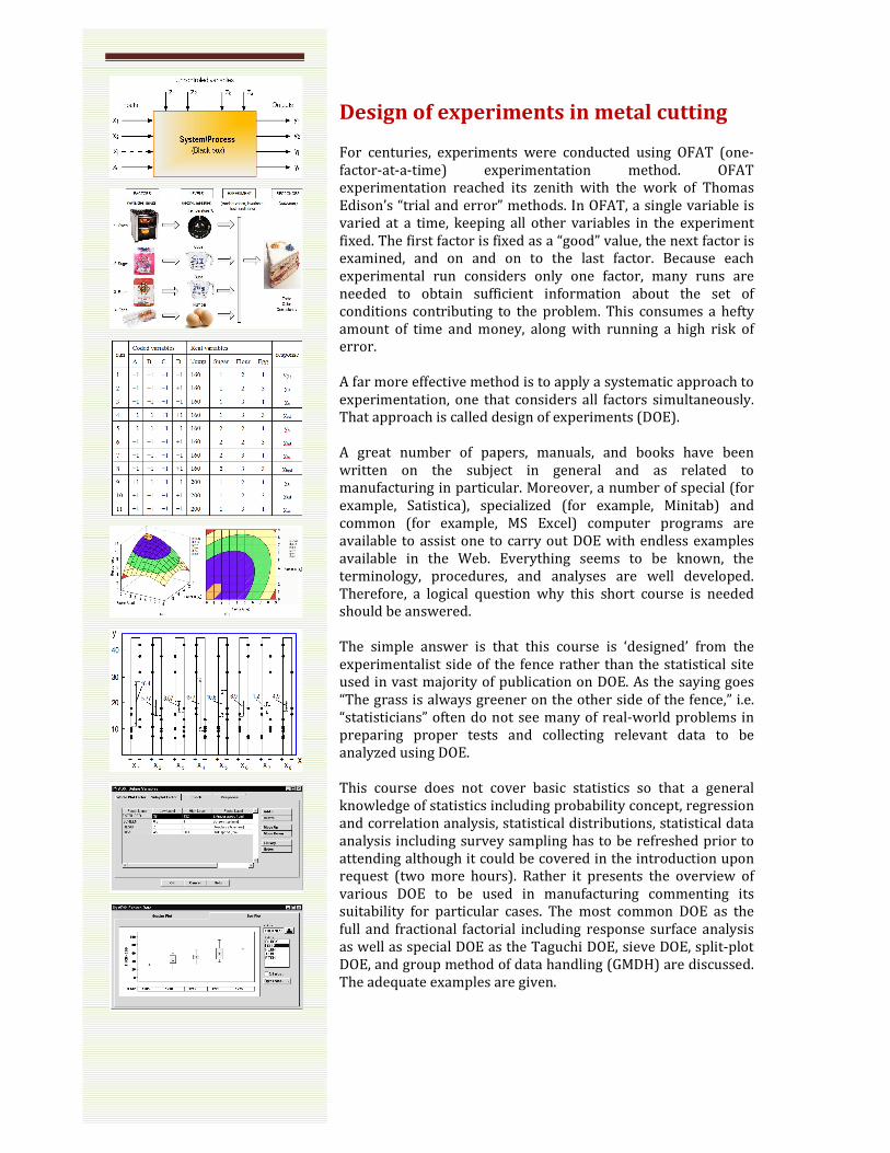
Design of experiments in metal cutting For centuries, experiments were conducted using OFAT (one-
factor-at-a-time) experimentation method. OFAT
experimentation reached its zenith with the work of Thomas
Edison’s “trial and error” methods. In OFAT, a single variable is
varied at a time, keeping all other variables in the experiment
fixed. The first factor is fixed as a “good” value, the next factor is
examined, and on and on to the last factor. Because each
experimental run considers only one factor, many runs are
needed to obtain sufficient information about the set of
conditions contributing to the problem. This consumes a hefty
amount of time and money, along with running a high risk of
error.
A far more effective method is to apply a systematic approach to
experimentation, one that considers all factors simultaneously.
That approach is called design of experiments (DOE).
A great number of papers, manuals, and books have been
written on the subject in general and as related to
manufacturing in particular. Moreover, a number of special (for
example, Satistica), specialized (for example, Minitab) and
common (for example, MS Excel) computer programs are
available to assist one to carry out DOE with endless examples
available in the Web. Everything seems to be known, the
terminology, procedures, and analyses are well developed.
Therefore, a logical question why this short course is needed
should be answered.
The simple answer is that this course is ‘designed’ from the
experimentalist side of the fence rather than the statistical site
used in vast majority of publication on DOE. As the saying goes
“The grass is always greener on the other side of the fence,” i.e.
“statisticians” often do not see many of real-world problems in
preparing proper tests and collecting relevant data to be
analyzed using DOE.
This course does not cover basic statistics so that a general
knowledge of statistics including probability concept, regression
and correlation analysis, statistical distributions, statistical data
analysis including survey sampling has to be refreshed prior to
attending although it could be covered in the introduction upon
request (two more hours). Rather it presents the overview of
various DOE to be used in manufacturing commenting its
suitability for particular cases. The most common DOE as the
full and fractional factorial including response surface analysis
as well as special DOE as the Taguchi DOE, sieve DOE, split-plot
DOE, and group method of data handling (GMDH) are discussed.
The adequate examples are given.

Finite Element Modeling (FEM) of metal
cutting A number of cutting theories and the FEM models have been
developed to model the metal cutting process in hope to
increase its efficiency and design the proper cutting tools. The
commercial codes MSC.Marc, Deform2D, and Thirdwave
AdvantEdge and others are readily available in the marketplace.
Although many of major manufacturing companies in the
automotive, aerospace, energy, tool industries have one or even
several commercial FEM codes, no one know to the trainer has
made a good use of these codes in the practice of the process
and tool design. The first part of the course aims to explain the
reasons.
The second part of the course explains that to obtain more
information (mechanics, chemistry, etc.) from the FEM an
appropriate about of information should be put in. This is
popularly expressed with the acronym “GIGO,” or “garbage in,
garbage out.” In other words, FEM simulations cannot generate
new knowledge. The results of such simulations are new data
that (provided the data are correct) help in practical operation
and cutting tool design.
The third part of the course answers the most important yet
non-answered question in all FEM simulation of metal cutting,
namely what to do with the result of simulations. Obtaining the
stress, temperature, strain, and other outputs, which are also
often set as the objective of the study or even of simulations,
cannot be considered as the final result because nobody really
knows how to use the data obtained for optimization fo any
practical machining operation and/or design the proper cutting
tool.
This forth part of the course aims to educate the listeners how
to do FEM of metal cutting properly about the concept of
authentication of FEM in metal cutting. This part of the course
concentrates on the fundamental issues with the use of FEM
analysis in metal cutting: the requirement for a physical model,
modeling of the behavior of materials during cutting, and the
verification of the FEM. The discussion of accurate physical
models provides the definition and objective of the metal cutting
system. The discussion of the behavior of materials during
cutting argues that the most common model of behavior, known
as the Johnson and Cook model, is unnecessary
overcomplicated. This forth part emphasizes that the
verification of the FEM is the final and mandatory stage in metal
cutting, with simple physics-based methods of FEM verification
discussed in details.

What does it mean “Metal Cutting”?
Basic equations and correlations used in metal cutting are
known phenomenologically, i.e. from the testing and
implementation practice of various tools. A little is known about
their physical nature. Unfortunately, these experience-based
facts are often incomplete and contradictive as they normally
considered ignoring system properties of the cutting system. As
a result, they cannot provide much guidance in the tool design in
terms of selection the optimal, for a given application, tool
geometry. The theory of metal cutting as taught in student’s
textbooks is of little help as it does not consider correlations
between essential parameters of the cutting tool geometry and
the physics of this process. Only when the physics of the metal
cutting process is understood and the system properties of the
metal cutting system are accounted for, the proper process
parameters and the right cutting tool can be selected. This,
however, can happen if the proper answer a simple question:
What is metal cutting? is known so one can answer to the
following questions:
1. What is the difference between metal cutting and cutting?
2. If a polymer or any other non-metal (wood, stone)
material is cut by means of turning, milling, drilling, etc., what
should this process be called?
3. What kind of cutting is performed by a knife or by a pair
of scissors?
This course aims to provide the answers to these questions
which will surprise many including seasoned professionals in
the field. These answers should help to distinguish metal cutting
among other closely related manufacturing operations revealing
its unique physical features controlled this process. The metal
cutting process is defined as a forming process, which takes
place in the components of the cutting system that are so
arranged that the external energy applied to the cutting system
causes the purposeful fracture of the layer being removed. This
fracture occurs due to the combined stress including the
continuously changing bending stress. The most important
property in metal cutting studies is the system time. The system
time was introduced as a new variable in the analysis of the
metal cutting system and it was conclusively proven that the
relevant properties of the cutting system’s components are time
dependent. The dynamic interactions of these components take
place in the cutting process, causing a cyclic nature of this
process.
The major outcome of the course is that the essence of the metal
cutting process can be understood so the parameters of any
machining operation can then be selected to optimize this
process.