Embed Size (px)
Citation preview
545www.hera.de | technical details are subject to change without notice ©2015
16. TRAINING SYSTEMS CONTROL AND AUTOMATION TECHNOLOGY, MECHATRONICS
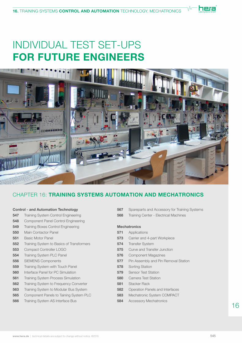
INDIVIDUAL TEST SET-UPS FOR FUTURE ENGINEERS
CHAPTER 16: TRAINING SYSTEMS AUTOMATION AND MECHATRONICS
Control - and Automation Technology
547 Training System Control Engineering
548 Component Panel Control Engineering
549 Training Boxes Control Engineering
550 Main Contactor Panel
551 Basic Motor Panel
552 Training System to Basics of Transformers
553 Compact Controller LOGO
554 Training System PLC Panel
556 SIEMENS Components
559 Training System with Touch Panel
560 Interface Panel for PC Simulation
561 Training System Process Simulation
562 Training System to Frequency Converter
563 Training System to Modular Bus System
565 Component Panels to Taining System PLC
566 Training System AS Interface Bus
567 Spareparts and Accessory for Training Systems
568 Training Center - Electrical Machines
Mechatronics
571 Applications
573 Carrier and 4-part Workpiece
574 Transfer System
575 Curve and Transfer Junction
576 Component Magazines
577 Pin Assembly and Pin Removal Station
578 Sorting Station
579 Sensor Test Station
580 Camera Test Station
581 Stacker Rack
582 Operation Panels and Interfaces
583 Mechatronic System COMPACT
584 Accessory Mechatronics
16
546 technical details are subject to change without notice ©2015 | www.hera.de
16. TRAINING SYSTEMS CONTROL AND AUTOMATION TECHNOLOGY, MECHATRONICS
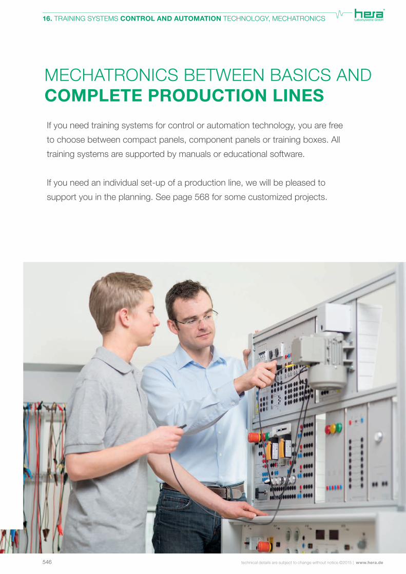
MECHATRONICS BETWEEN BASICS AND COMPLETE PRODUCTION LINES
If you need training systems for control or automation technology, you are free
to choose between compact panels, component panels or training boxes. All
training systems are supported by manuals or educational software.
If you need an individual set-up of a production line, we will be pleased to
support you in the planning. See page 568 for some customized projects.
547www.hera.de | technical details are subject to change without notice ©2015
16. TRAINING SYSTEMS CONTROL AND AUTOMATION TECHNOLOGY, MECHATRONICS
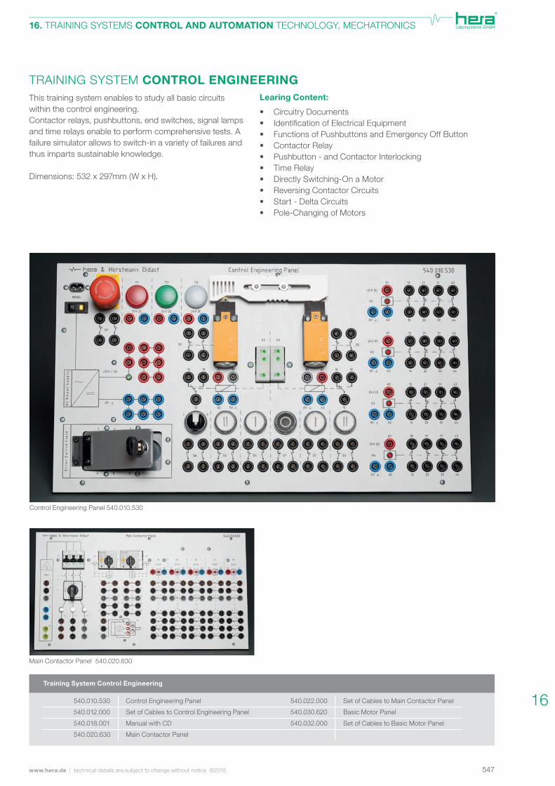
TRAINING SYSTEM CONTROL ENGINEERINGThis training system enables to study all basic circuits within the control engineering. Contactor relays, pushbuttons, end switches, signal lamps and time relays enable to perform comprehensive tests. A failure simulator allows to switch-in a variety of failures and thus imparts sustainable knowledge.
Dimensions: 532 x 297mm (W x H).
Learing Content:
• Circuitry Documents• IdentificationofElectricalEquipment • Functions of Pushbuttons and Emergency Off Button • Contactor Relay • Pushbutton - and Contactor Interlocking • Time Relay • Directly Switching-On a Motor • Reversing Contactor Circuits • Start - Delta Circuits• Pole-Changing of Motors
Training System Control Engineering
Control Engineering Panel
Set of Cables to Control Engineering Panel
Manual with CD
Main Contactor Panel
Set of Cables to Main Contactor Panel
Basic Motor Panel
Set of Cables to Basic Motor Panel
Control Engineering Panel 540.010.530
Main Contactor Panel 540.020.630
540.010.530
540.012.000
540.018.001
540.020.630
540.022.000
540.030.620
540.032.000
16
548 technical details are subject to change without notice ©2015 | www.hera.de
16. TRAINING SYSTEMS CONTROL AND AUTOMATION TECHNOLOGY, MECHATRONICS
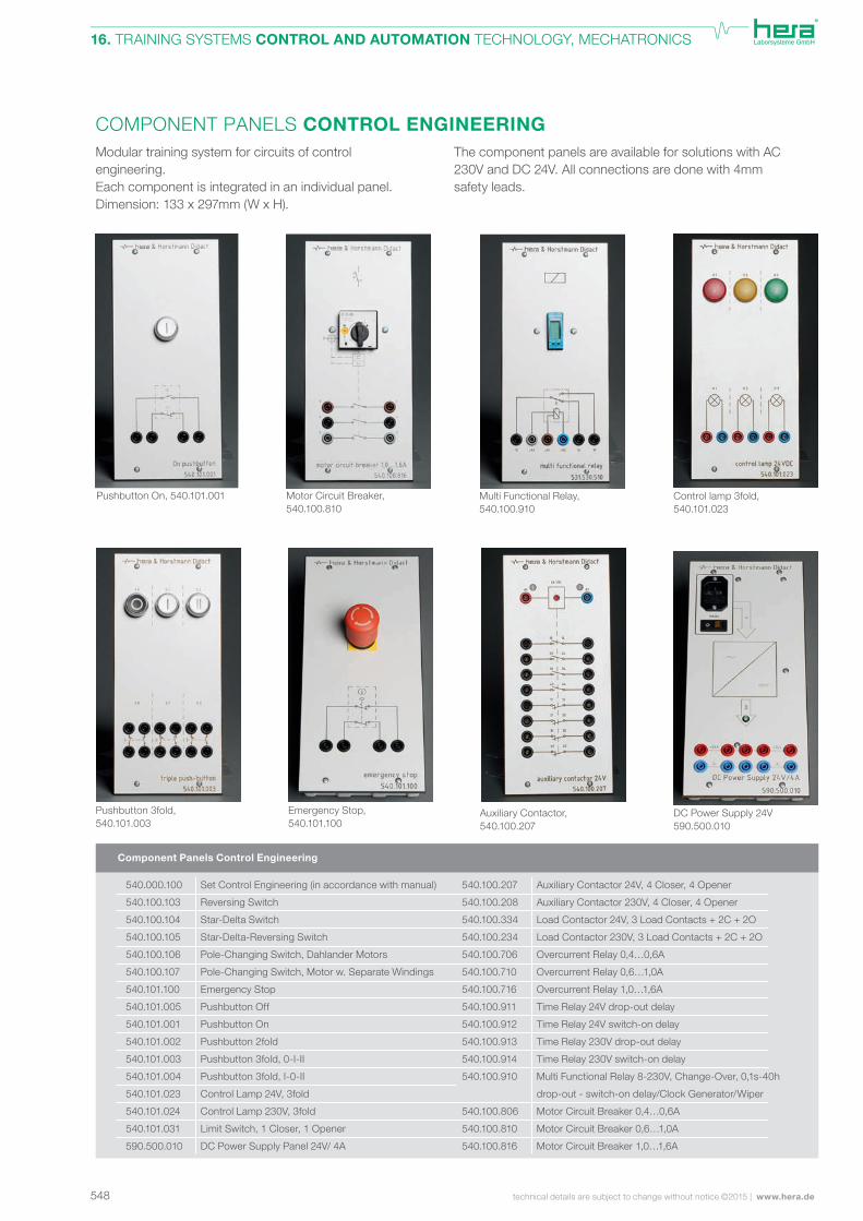
The component panels are available for solutions with AC 230V and DC 24V. All connections are done with 4mm safety leads.
COMPONENT PANELS CONTROL ENGINEERINGModular training system for circuits of control engineering. Each component is integrated in an individual panel.Dimension: 133 x 297mm (W x H).
Pushbutton On, 540.101.001 Motor Circuit Breaker,540.100.810
Multi Functional Relay,540.100.910
Control lamp 3fold,540.101.023
DC Power Supply 24V 590.500.010
Auxiliary Contactor,540.100.207
Emergency Stop,540.101.100
Pushbutton 3fold,540.101.003
Component Panels Control Engineering
Set Control Engineering (in accordance with manual)
Reversing Switch
Star-Delta Switch
Star-Delta-Reversing Switch
Pole-Changing Switch, Dahlander Motors
Pole-Changing Switch, Motor w. Separate Windings
Emergency Stop
Pushbutton Off
Pushbutton On
Pushbutton 2fold
Pushbutton 3fold, 0-I-II
Pushbutton 3fold, I-0-II
Control Lamp 24V, 3fold
Control Lamp 230V, 3fold
Limit Switch, 1 Closer, 1 Opener
DC Power Supply Panel 24V/ 4A
Auxiliary Contactor 24V, 4 Closer, 4 Opener
Auxiliary Contactor 230V, 4 Closer, 4 Opener
Load Contactor 24V, 3 Load Contacts + 2C + 2O
Load Contactor 230V, 3 Load Contacts + 2C + 2O
Overcurrent Relay 0,4…0,6A
Overcurrent Relay 0,6…1,0A
Overcurrent Relay 1,0…1,6A
Time Relay 24V drop-out delay
Time Relay 24V switch-on delay
Time Relay 230V drop-out delay
Time Relay 230V switch-on delay
Multi Functional Relay 8-230V, Change-Over, 0,1s-40h
drop-out - switch-on delay/Clock Generator/Wiper
Motor Circuit Breaker 0,4…0,6A
Motor Circuit Breaker 0,6…1,0A
Motor Circuit Breaker 1,0…1,6A
540.000.100
540.100.103
540.100.104
540.100.105
540.100.106
540.100.107
540.101.100
540.101.005
540.101.001
540.101.002
540.101.003
540.101.004
540.101.023
540.101.024
540.101.031
590.500.010
540.100.207
540.100.208
540.100.334
540.100.234
540.100.706
540.100.710
540.100.716
540.100.911
540.100.912
540.100.913
540.100.914
540.100.910
540.100.806
540.100.810
540.100.816
549www.hera.de | technical details are subject to change without notice ©2015
16. TRAINING SYSTEMS CONTROL AND AUTOMATION TECHNOLOGY, MECHATRONICS
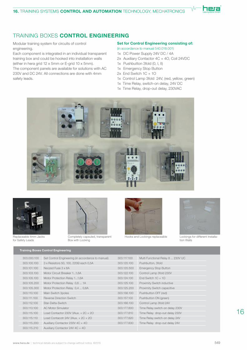
TRAINING BOXES CONTROL ENGINEERINGModular training system for circuits of control engineering. Each component is integrated in an individual transparent training box and could be hooked into installation walls (either in hera grid 12 x 5mm or E-grid 10 x 5mm).The component panels are available for solutions with AC 230V and DC 24V. All connections are done with 4mm safety leads.
Set for Control Engineering consisting of:(in accordance to manual 540.018.001)
1x DC Power Supply 24V DC / 4A2x Auxiliary Contactor 4C + 4O, Coil 24VDC1x Pushbutton 3fold (0, I, II)1x Emergency Stop Button2x End Switch 1C + 1O1x Control Lamp 3fold 24V, (red, yellow, green)1x Time Relay, switch-on delay, 24V DC1x Time Relay, drop-out delay, 230VAC
Replaceable 4mm Jacks for Safety Leads
Completely capsuled, transparentBox with Locking
Hooks and Lockings replaceable Lockings for different Installa-tion Walls
Training Boxes Control Engineering
Set Control Engineering (in accordance to manual)
3xResistors50,100,220Ωeach0,5A
Neozed Fuse 3 x 6A
Motor Circuit Breaker 1...1,6A
Motor Protection Relay 1...1,6A
Motor Protection Relay 0,6 ... 1A
Motor Protection Relay 0,4 ... 0,6A
Main Switch 3poles
Reverse Direction Switch
Star-Delta-Switch
AC Motor Simulator
Load Contactor 230V 3Aux. + 2C + 2O
Load Contacotr 24V 3Aux. + 2C + 2O
Auxiliary Contactor 230V 4C + 4O
Auxiliary Contactor 24V 4C + 4O
Multi Functional Relay 8 ... 230V UC
Pushbutton, 3fold
Emergency Stop Button
Control Lamp 3fold 230V
End Switch 1C + 1O
Proximity Switch inductive
Proximity Switch capacitive
Pushbutton OFF (red)
Pushbutton ON (green)
Control Lamp 3fold 24V
Time Relay switch-on delay 230V
Time Relay drop-out delay 230V
Time Relay switch-on delay 24V
Time Relay drop-out delay 24V
303.000.100
303.100.100
303.101.100
303.103.100
303.105.100
303.105.200
303.105.300
303.110.100
303.111.100
303.112.100
303.113.100
303.115.100
303.115.110
303.115.200
303.115.210
303.117.100
303.120.100
303.120.500
303.122.100
303.124.100
303.125.100
303.125.200
303.156.100
303.157.100
303.166.100
303.177.800
303.177.810
303.177.820
303.177.830
16
550 technical details are subject to change without notice ©2015 | www.hera.de
16. TRAINING SYSTEMS CONTROL AND AUTOMATION TECHNOLOGY, MECHATRONICS
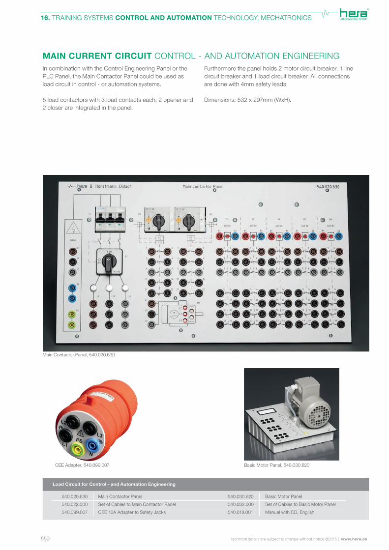
MAIN CURRENT CIRCUIT CONTROL - AND AUTOMATION ENGINEERINGFurthermore the panel holds 2 motor circuit breaker, 1 line circuit breaker and 1 load circuit breaker. All connections are done with 4mm safety leads.
Dimensions: 532 x 297mm (WxH).
In combination with the Control Engineering Panel or the PLC Panel, the Main Contactor Panel could be used as load circuit in control - or automation systems. 5 load contactors with 3 load contacts each, 2 opener and 2 closer are integrated in the panel.
CEE Adapter, 540.099.007
Load Circuit for Control - and Automation Engineering
Main Contactor Panel
Set of Cables to Main Contactor Panel
CEE 16A Adapter to Safety Jacks
Basic Motor Panel
Set of Cables to Basic Motor Panel
Manual with CD, English
Main Contactor Panel, 540.020.630
Basic Motor Panel, 540.030.620
540.020.630
540.022.000
540.099.007
540.030.620
540.032.000
540.018.001
551www.hera.de | technical details are subject to change without notice ©2015
16. TRAINING SYSTEMS CONTROL AND AUTOMATION TECHNOLOGY, MECHATRONICS
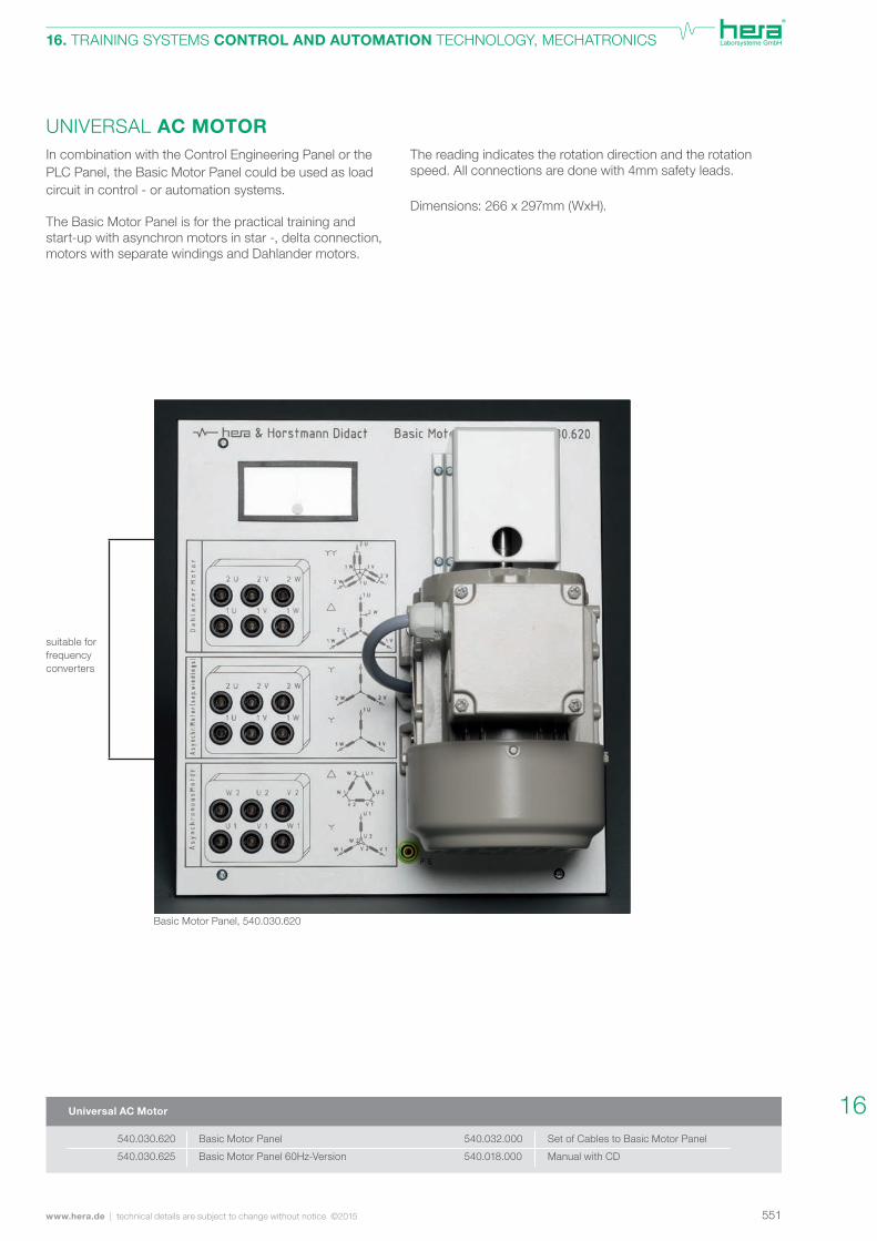
UNIVERSAL AC MOTORIn combination with the Control Engineering Panel or the PLC Panel, the Basic Motor Panel could be used as load circuit in control - or automation systems. The Basic Motor Panel is for the practical training and start-up with asynchron motors in star -, delta connection, motors with separate windings and Dahlander motors.
The reading indicates the rotation direction and the rotation speed. All connections are done with 4mm safety leads.
Dimensions: 266 x 297mm (WxH).
suitable for frequency converters
Universal AC Motor
Basic Motor Panel
Basic Motor Panel 60Hz-Version
Set of Cables to Basic Motor Panel
Manual with CD
540.030.620
540.030.625
540.032.000
540.018.000
Basic Motor Panel, 540.030.620
16
552 technical details are subject to change without notice ©2015 | www.hera.de
16. TRAINING SYSTEMS CONTROL AND AUTOMATION TECHNOLOGY, MECHATRONICS
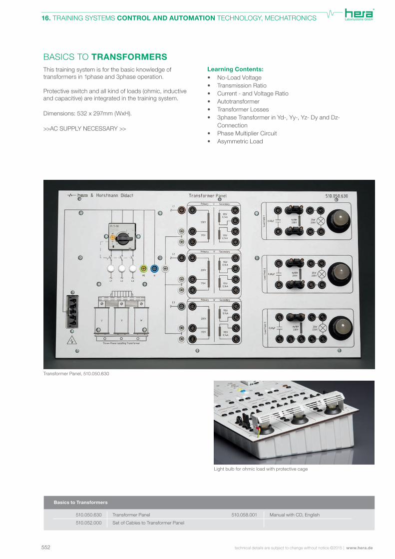
BASICS TO TRANSFORMERSLearning Contents:• No-Load Voltage• Transmission Ratio• Current - and Voltage Ratio• Autotransformer• Transformer Losses• 3phase Transformer in Yd-, Yy-, Yz- Dy and Dz- Connection• Phase Multiplier Circuit• Asymmetric Load
This training system is for the basic knowledge of transformers in 1phase and 3phase operation. Protective switch and all kind of loads (ohmic, inductive and capacitive) are integrated in the training system.
Dimensions: 532 x 297mm (WxH).
>>AC SUPPLY NECESSARY >>
Manual with CD, English Transformer Panel
Set of Cables to Transformer Panel
Basics to Transformers
Transformer Panel, 510.050.630
510.050.630
510.052.000
510.058.001
Light bulb for ohmic load with protective cage

553www.hera.de | technical details are subject to change without notice ©2015
16. TRAINING SYSTEMS CONTROL AND AUTOMATION TECHNOLOGY, MECHATRONICS
Inputs are connected to safety jacks and with latching
pushbuttons.
Outputs are relay outputs (DRO) or trasistor outputs (DTO)
connected to safety jacks.
Dimensions: 266 x 297mm.
LOGIC CONTROLLERLogic controllers are the ideal control for small machines or
comfort house-installations.
The hera training system allows the set-up and training
with logic controllers of different brands.
Thismodulartrainingsystemallowsconfigurationswith
controll dependent in- and outputs. All systems come with
software and PC connecting cable.
Training System LOGO!, 550.980.022 Training System Millenium 3, 550.980.044
Compact Controller
Training System SIEMENS LOGO! 8 12/24V with 12x DI and 8x DRO (4x DI applicable as AI (0-10V)) incl. LOGO! Soft Comfort V8
Training System SIEMENS LOGO! 8 230V with 12x DI and 8x DRO incl. LOGO! Soft Comfort V8
Additional Siemens Module for Temperature Measurement (2x AI for Pt100/Pt1000) and suitable panel addition
Manual English „Controlling with the LOGO!“
Training System Easy 24V (8x DI + 4x DRO)
Training System Easy 230V (8x DI + 4x DRO)
Training System Easy 24V (12x DI + 8x DRO)
Training System Easy 230V (12x DI + 6x DRO)
550.980.025
550.980.026
550.980.027
550.988.024
550.980.030
550.980.031
550.980.032
550.980.033
16
554 technical details are subject to change without notice ©2015 | www.hera.de
16. TRAINING SYSTEMS CONTROL AND AUTOMATION TECHNOLOGY, MECHATRONICS
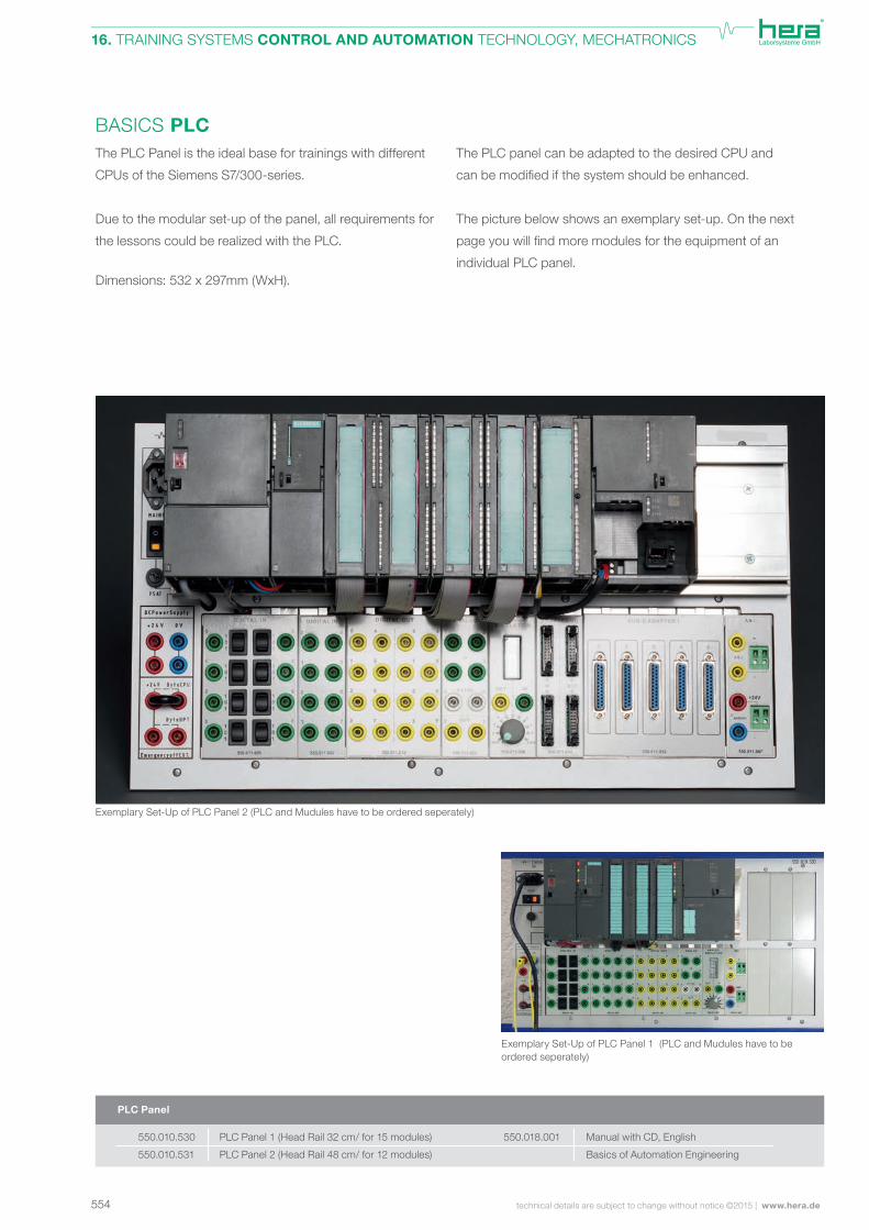
BASICS PLCThe PLC Panel is the ideal base for trainings with different
CPUs of the Siemens S7/300-series.
Due to the modular set-up of the panel, all requirements for
the lessons could be realized with the PLC.
Dimensions: 532 x 297mm (WxH).
The PLC panel can be adapted to the desired CPU and
canbemodifiedifthesystemshouldbeenhanced.
The picture below shows an exemplary set-up. On the next
pageyouwillfindmoremodulesfortheequipmentofan
individual PLC panel.
Exemplary Set-Up of PLC Panel 2 (PLC and Mudules have to be ordered seperately)
Exemplary Set-Up of PLC Panel 1 (PLC and Mudules have to be ordered seperately)
PLC Panel 1 (Head Rail 32 cm/ for 15 modules)
PLC Panel 2 (Head Rail 48 cm/ for 12 modules)
Manual with CD, English
Basics of Automation Engineering
PLC Panel
550.010.530
550.010.531
550.018.001
555www.hera.de | technical details are subject to change without notice ©2015
16. TRAINING SYSTEMS CONTROL AND AUTOMATION TECHNOLOGY, MECHATRONICS
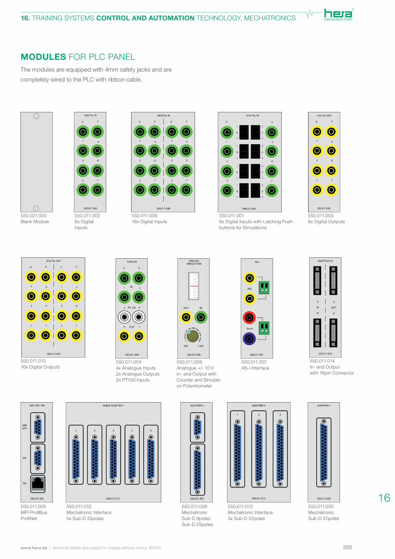
MODULES FOR PLC PANELThe modules are equipped with 4mm safety jacks and are
completely wired to the PLC with ribbon cable.
550.021.000Blank Module
550.011.0028x DigitalInputs
550.011.00916x Digital Inputs
550.011.0018x Digital Inputs with Latching Push-buttons for Simulations
550.011.01016x Digital Outputs
550.011.0044x Analogue Inputs2x Analogue Outputs2x PT100 Inputs
550.011.008Analogue +/- 10 VIn- and Output with Counter and Simulati-on Potentiometer
550.011.007AS-i Interface
550.011.012Mechatronic Interface5x Sub-D 25poles
550.011.005MPIProfiBusProfiNet
550.011.006MechatronicSub-D 9polesSub-D 25poles
550.011.013Mechatronic Interface3x Sub-D 37poles
550.011.0038x Digital Outputs
550.011.014In- and Outputwith 16pin Connector
550.011.030MechatronicSub-D 37poles
16
556 technical details are subject to change without notice ©2015 | www.hera.de
16. TRAINING SYSTEMS CONTROL AND AUTOMATION TECHNOLOGY, MECHATRONICS
Ethernet CableMicro Memory Card
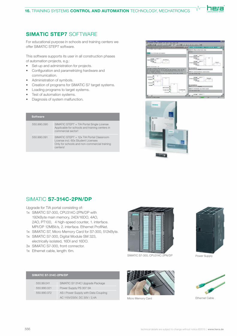
SIMATIC S7-314C-2PN/DP
SIMATIC S7-314C Upgrade Package
Power Supply PS 307 5A
AS-i Power Supply with Data Coupling
AC 115V/230V, DC 30V / 2,4A
550.99.041
550.990.021
550.990.072
SIMATIC STEP7 SOFTWAREFor educational purpose in schools and training centers we offer SIMATIC STEP7 software.
This software supports its user in all construction phases of automation projects, e.g.:• Set-up and administration for projects.• Configurationandparametrizinghardwareand communication.• Administration of symbols.• Creation of programs for SIMATIC S7 target systems.• Loading programs to target systems.• Test of automation systems.• Diagnosis of system malfunction.
SIMATIC STEP7 + 12x TIA Portal Classroom License incl. 60x Student LicensesOnly for schools and non-commercial training centers!
SIMATIC STEP7 + TIA Portal Single LicenseApplicable for schools and training centers in commercial sector!
550.990.090
550.990.091
Software
SIMATIC S7-300: CPUs (without power supply and MMC) SIMATIC S7-300: Input-Output-Units
SIMATIC S7-300: Power Supply
Power SupplySIMATIC S7-300, CPU314C-2PN/DP
Upgrade for TIA portal consisting of:1x SIMATIC S7-300, CPU314C-2PN/DP with 192kByte main memory, 24DI/16DO, 4AO, 2AO, PT100, 4 high-speed counter, 1. interface. MPI/DP12MBit/s,2.interface.EthernetProfiNet.1x SIMATIC S7, Micro Memory Card for S7-300, 512kByte.1x SIMATIC S7-300, Digital Module SM 323, electrically isolated, 16DI and 16DO.3x SIMATIC S7-300, front connector.1x Ethernet cable, length: 6m.
SIMATIC S7-314C-2PN/DP
557www.hera.de | technical details are subject to change without notice ©2015
16. TRAINING SYSTEMS CONTROL AND AUTOMATION TECHNOLOGY, MECHATRONICS
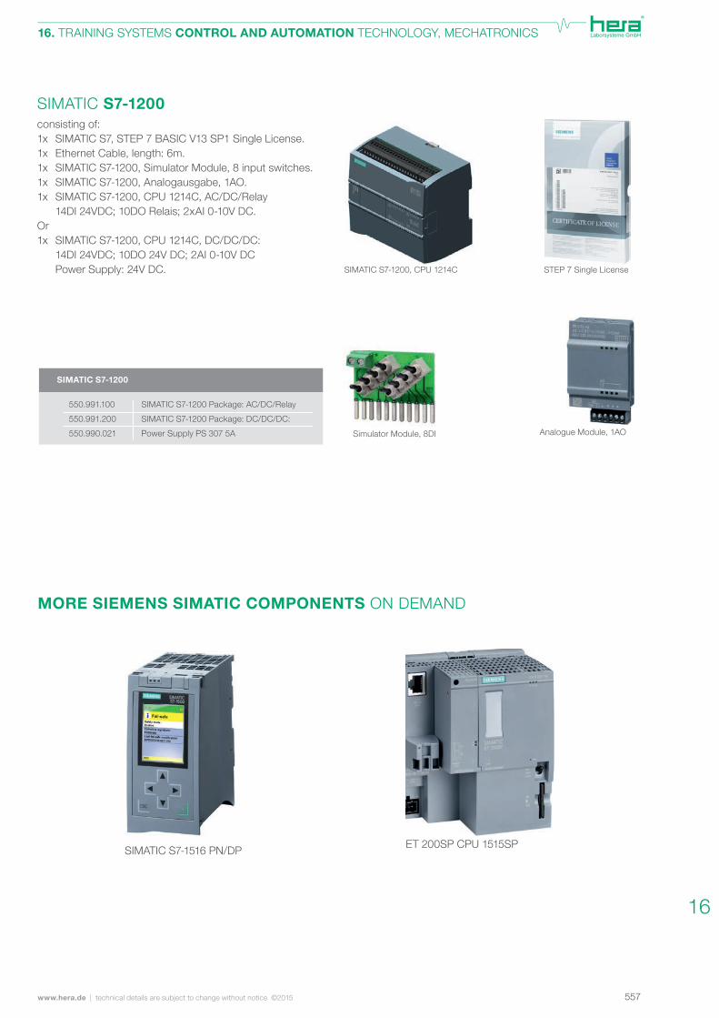
STEP 7 Single LicenseSIMATIC S7-1200, CPU 1214C
consisting of:1x SIMATIC S7, STEP 7 BASIC V13 SP1 Single License.1x Ethernet Cable, length: 6m.1x SIMATIC S7-1200, Simulator Module, 8 input switches.1x SIMATIC S7-1200, Analogausgabe, 1AO.1x SIMATIC S7-1200, CPU 1214C, AC/DC/Relay 14DI 24VDC; 10DO Relais; 2xAI 0-10V DC.Or1x SIMATIC S7-1200, CPU 1214C, DC/DC/DC: 14DI 24VDC; 10DO 24V DC; 2AI 0-10V DC Power Supply: 24V DC.
SIMATIC S7-1200
Simulator Module, 8DI Analogue Module, 1AO
SIMATIC S7-1200
SIMATIC S7-1200 Package: AC/DC/Relay
SIMATIC S7-1200 Package: DC/DC/DC:
Power Supply PS 307 5A
550.991.100
550.991.200
550.990.021
ET 200SP CPU 1515SPSIMATIC S7-1516 PN/DP
MORE SIEMENS SIMATIC COMPONENTS ON DEMAND
16
558 technical details are subject to change without notice ©2015 | www.hera.de
16. TRAINING SYSTEMS CONTROL AND AUTOMATION TECHNOLOGY, MECHATRONICS
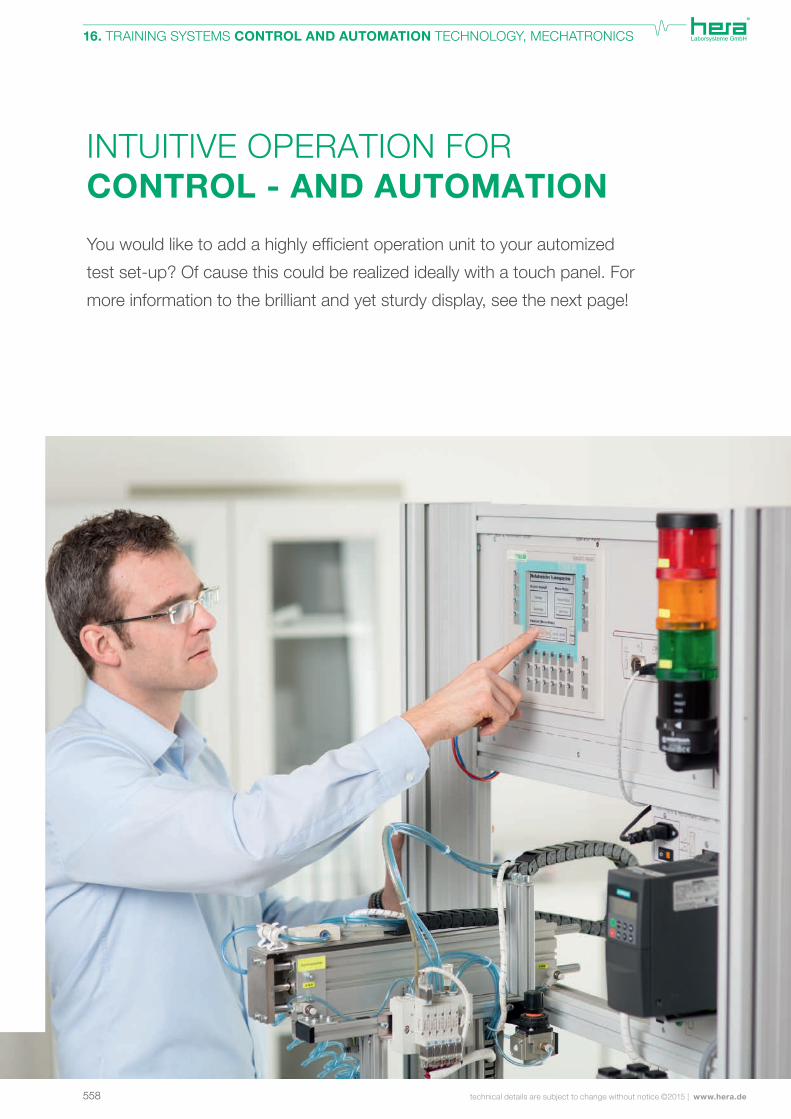
INTUITIVE OPERATION FOR CONTROL - AND AUTOMATION
Youwouldliketoaddahighlyefficientoperationunittoyourautomized
test set-up? Of cause this could be realized ideally with a touch panel. For
more information to the brilliant and yet sturdy display, see the next page!
559www.hera.de | technical details are subject to change without notice ©2015
16. TRAINING SYSTEMS CONTROL AND AUTOMATION TECHNOLOGY, MECHATRONICS
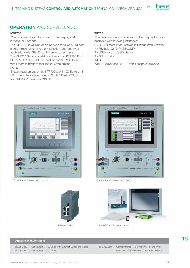
OPERATION AND SURVEILLANCE
Operation and Surveillance
TP700:7“ wide screen Touch Panel with colour display for touch operation with following interfaces:2xRJ45EthernetforProfiNet(mitintegriertemSwitch)1xRS485/422fürProfiBus/MPI2 x USB-host, 1 x USB- device2 x SD card slotINFO:WIN CC Advanced 13 SP1 within scope of delivery!
KTP700:7“ wide screen Touch Panel with colour display and 8 buttons for functions.The KTP700 Basic is an operator panel for simple HMI with medium requirements to the visulization functionality of applications with S7-122 controllers or other logics.The KTP700 Basic is available in 2 versions: KTP700 Basic DPforMPI/ProfiBusDPconnectionandKTP700BasicwithEthernetInterfaceforProfiNetenvironment.NOTE:System requirement for the KTP700 is WIN CC Basic V 13 SP1. The software is included in STEP 7 Basic V13 SP1 and STEP 7 Professional V13 SP1.
Incl. WinCC and Ethernet CableEthernet Switch
Comfort Panel, Art-No.: 550.060.320Touch Panel, Art-No.: 550.055.320
Comfort Panel TP700 with ProfiNet and MPI/
ProfiBus DP Interface incl. Cable and Software
550.060.320 Touch Panel KTP700 Basic with Ethernet Switch and Cable
Touch Panel KTP700 Basic DP
550.055.320
550.056.320
16
560 technical details are subject to change without notice ©2015 | www.hera.de
16. TRAINING SYSTEMS CONTROL AND AUTOMATION TECHNOLOGY, MECHATRONICS
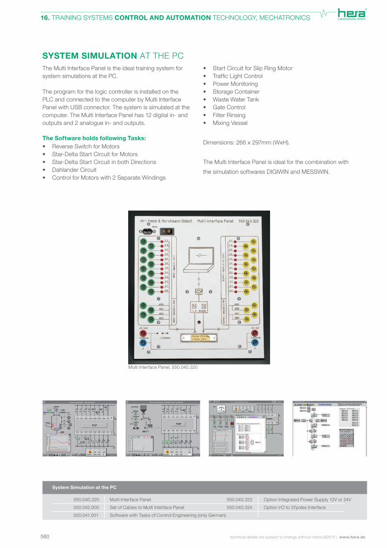
SYSTEM SIMULATION AT THE PCThe Multi Interface Panel is the ideal training system for system simulations at the PC.
The program for the logic controller is installed on the PLC and connected to the computer by Multi Interface Panel with USB connector. The system is simulated at the computer. The Multi Interface Panel has 12 digital in- and outputs and 2 analogue in- and outputs.
The Software holds following Tasks:• Reverse Switch for Motors • Star-Delta Start Circuit for Motors • Star-Delta Start Circuit in both Directions • Dahlander Circuit • Control for Motors with 2 Separate Windings
• Start Circuit for Slip Ring Motor • TrafficLightControl • Power Monitoring • Storage Container • Waste Water Tank • Gate Control • Filter Rinsing • Mixing Vessel
Dimensions: 266 x 297mm (WxH).
The Multi Interface Panel is ideal for the combination with
the simulation softwares DIGIWIN and MESSWIN.
System Simulation at the PC
Multi Interface Panel
Set of Cables to Multi Interface Panel
Software with Tasks of Control Engineering (only German)
Option Integrated Power Supply 12V or 24V
Option I/O to 37poles Interface
Multi Interface Panel, 550.040.320
550.040.320
550.042.000
550.041.001
550.040.322
550.040.324
561www.hera.de | technical details are subject to change without notice ©2015
16. TRAINING SYSTEMS CONTROL AND AUTOMATION TECHNOLOGY, MECHATRONICS
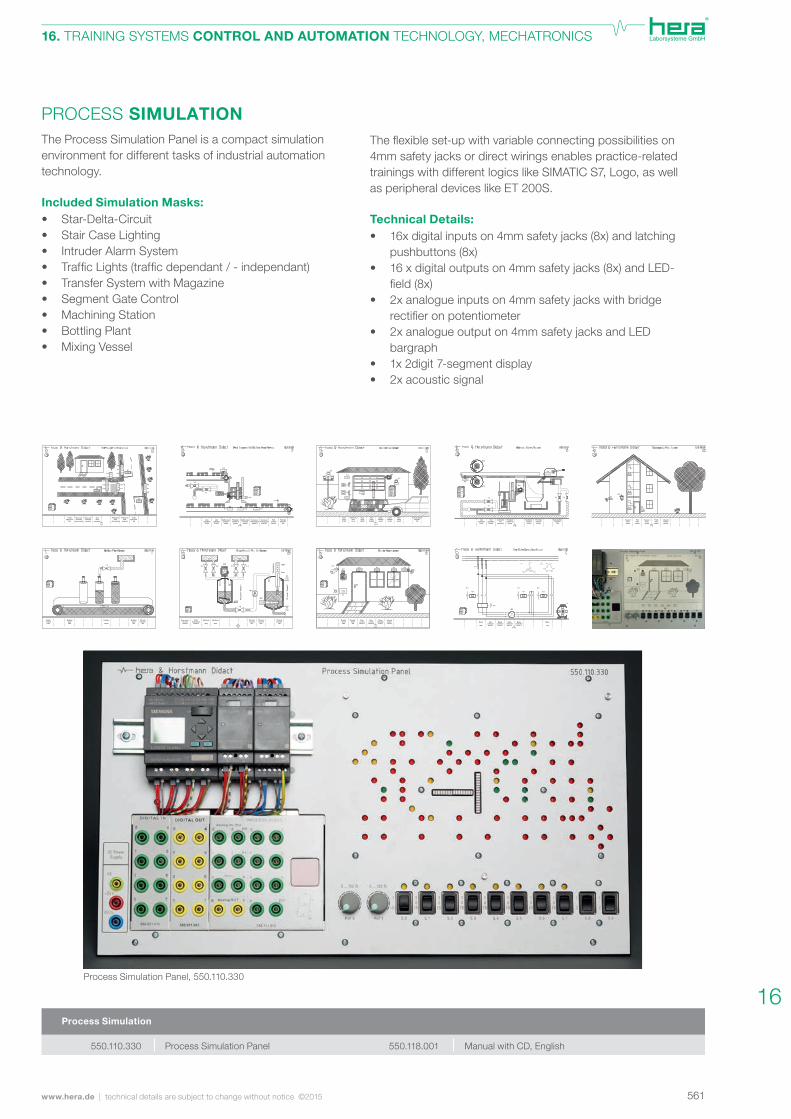
Theflexibleset-upwithvariableconnectingpossibilitieson4mm safety jacks or direct wirings enables practice-related trainings with different logics like SIMATIC S7, Logo, as well as peripheral devices like ET 200S. Technical Details:• 16x digital inputs on 4mm safety jacks (8x) and latching pushbuttons (8x) • 16 x digital outputs on 4mm safety jacks (8x) and LED- field(8x) • 2x analogue inputs on 4mm safety jacks with bridge rectifieronpotentiometer • 2x analogue output on 4mm safety jacks and LED bargraph • 1x 2digit 7-segment display • 2x acoustic signal
PROCESS SIMULATIONThe Process Simulation Panel is a compact simulation environment for different tasks of industrial automation technology.
Included Simulation Masks:• Star-Delta-Circuit • Stair Case Lighting • Intruder Alarm System • TrafficLights(trafficdependant/-independant) • Transfer System with Magazine • Segment Gate Control • Machining Station • Bottling Plant • Mixing Vessel
Process Simulation Panel Manual with CD, English
Process Simulation
Process Simulation Panel, 550.110.330
550.110.330 550.118.001
16
562
FC Motor Panel, Artikel-Nr.: 570.021.520
technical details are subject to change without notice ©2015 | www.hera.de
16. TRAINING SYSTEMS CONTROL AND AUTOMATION TECHNOLOGY, MECHATRONICS
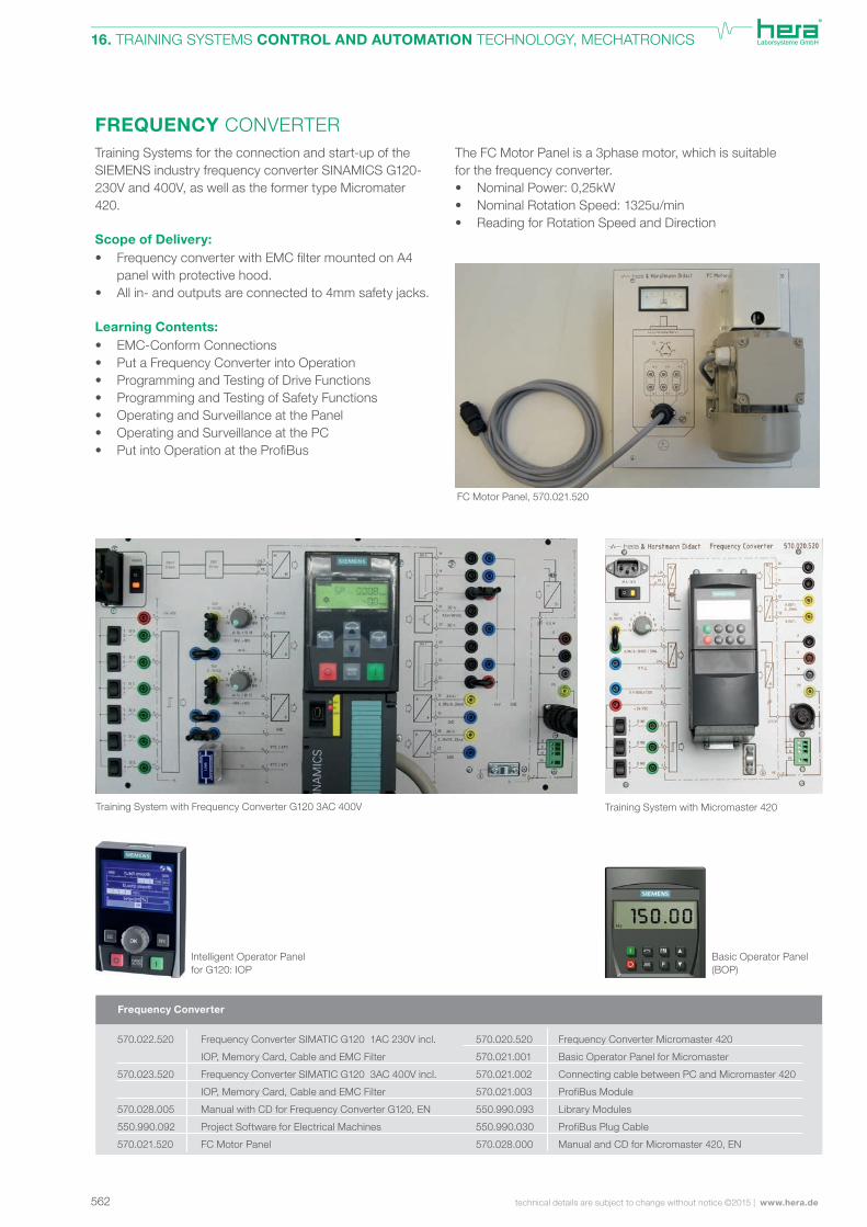
FREQUENCY CONVERTERThe FC Motor Panel is a 3phase motor, which is suitable for the frequency converter. • Nominal Power: 0,25kW • Nominal Rotation Speed: 1325u/min • Reading for Rotation Speed and Direction
Training Systems for the connection and start-up of the SIEMENS industry frequency converter SINAMICS G120-230V and 400V, as well as the former type Micromater 420.
Scope of Delivery:• FrequencyconverterwithEMCfiltermountedonA4 panel with protective hood. • All in- and outputs are connected to 4mm safety jacks. Learning Contents:• EMC-Conform Connections • Put a Frequency Converter into Operation • Programming and Testing of Drive Functions • Programming and Testing of Safety Functions • Operating and Surveillance at the Panel • Operating and Surveillance at the PC • PutintoOperationattheProfiBus
FC Motor Panel, 570.021.520
Frequency Converter
Basic Operator Panel (BOP)
Intelligent Operator Panel for G120: IOP
Training System with Frequency Converter G120 3AC 400V Training System with Micromaster 420
Frequency Converter SIMATIC G120 1AC 230V incl.
IOP, Memory Card, Cable and EMC Filter
Frequency Converter SIMATIC G120 3AC 400V incl.
IOP, Memory Card, Cable and EMC Filter
Manual with CD for Frequency Converter G120, EN
Project Software for Electrical Machines
FC Motor Panel
570.022.520
570.023.520
570.028.005
550.990.092
570.021.520
Frequency Converter Micromaster 420
Basic Operator Panel for Micromaster
Connecting cable between PC and Micromaster 420
ProfiBus Module
Library Modules
ProfiBus Plug Cable
Manual and CD for Micromaster 420, EN
570.020.520
570.021.001
570.021.002
570.021.003
550.990.093
550.990.030
570.028.000
563www.hera.de | technical details are subject to change without notice ©2015
16. TRAINING SYSTEMS CONTROL AND AUTOMATION TECHNOLOGY, MECHATRONICS
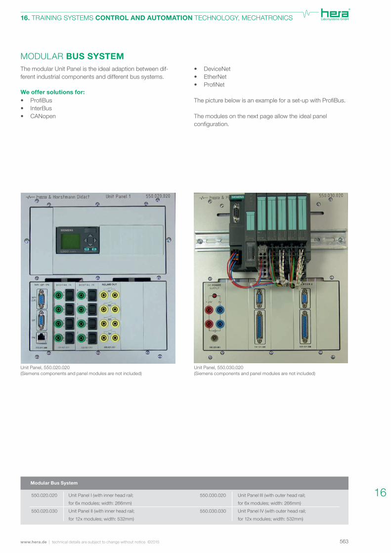
MODULAR BUS SYSTEMThe modular Unit Panel is the ideal adaption between dif-ferent industrial components and different bus systems. We offer solutions for:• ProfiBus • InterBus • CANopen
• DeviceNet • EtherNet • ProfiNet
Thepicturebelowisanexampleforaset-upwithProfiBus.
The modules on the next page allow the ideal panel configuration.
Unit Panel, 550.020.020(Siemens components and panel modules are not included)
Unit Panel, 550.030.020(Siemens components and panel modules are not included)
Modular Bus System
Unit Panel III (with outer head rail;
for 6x modules; width: 266mm)
Unit Panel IV (with outer head rail;
for 12x modules; width: 532mm)
Unit Panel I (with inner head rail;
for 6x modules; width: 266mm)
Unit Panel II (with inner head rail;
for 12x modules; width: 532mm)
550.020.020
550.020.030
550.030.020
550.030.030
16

564 technical details are subject to change without notice ©2015 | www.hera.de
16. TRAINING SYSTEMS CONTROL AND AUTOMATION TECHNOLOGY, MECHATRONICS
BUS SYSTEM MODULES FOR UNIT PANELSThe modules are equipped with 4mm safety jacks and are wired on the panel to the industrial components and bus systems.
550.021.000Blank Module
550.021.00124 V DC withSafety Jacks+ DC Connector
550.021.002230V Mains Connector
550.021.003230V AC Power Supply Safety Jacks
550.021.030InterfaceSub-D 9polesSub-D 25poles
550.021.031InterfaceSub-D 37poles
550.021.0108x DigitalInputs
550.021.0208x DigitalOutputs
550.021.0214x RelayOutputs
550.021.0156x Digital Inputswith Latching Pushbuttons4x Digital Outputs
550.021.0294x Analogue Inputs2x Analogue Outputs2x PT100 Inputs
550.021.0166x Digital Inputs with Latching Pushbuttons4x Relay Outputs
550.021.0114x DigitalInputs with Latching Push-buttons
565www.hera.de | technical details are subject to change without notice ©2015
16. TRAINING SYSTEMS CONTROL AND AUTOMATION TECHNOLOGY, MECHATRONICS
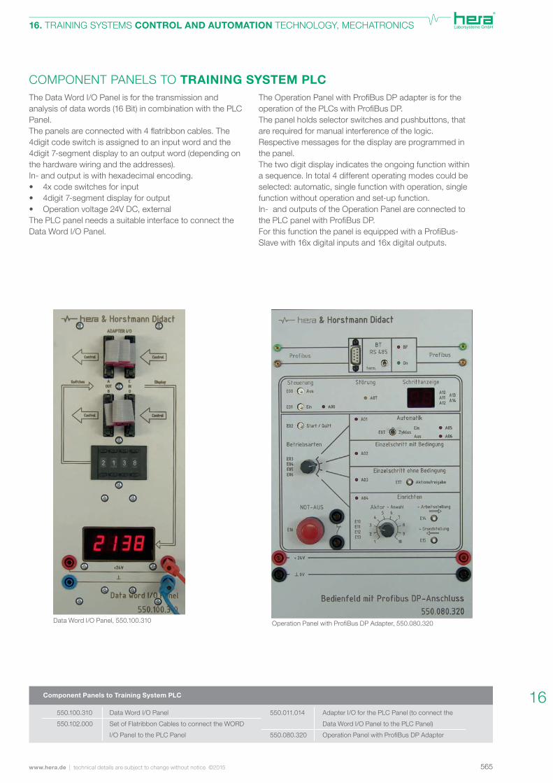
COMPONENT PANELS TO TRAINING SYSTEM PLCThe Data Word I/O Panel is for the transmission and analysis of data words (16 Bit) in combination with the PLC Panel. Thepanelsareconnectedwith4flatribboncables.The4digit code switch is assigned to an input word and the 4digit 7-segment display to an output word (depending on the hardware wiring and the addresses).In- and output is with hexadecimal encoding.• 4x code switches for input• 4digit 7-segment display for output• Operation voltage 24V DC, externalThe PLC panel needs a suitable interface to connect the Data Word I/O Panel.
TheOperationPanelwithProfiBusDPadapterisfortheoperationofthePLCswithProfiBusDP. The panel holds selector switches and pushbuttons, that are required for manual interference of the logic. Respective messages for the display are programmed in the panel. The two digit display indicates the ongoing function within a sequence. In total 4 different operating modes could be selected: automatic, single function with operation, single function without operation and set-up function. In- and outputs of the Operation Panel are connected to thePLCpanelwithProfiBusDP.ForthisfunctionthepanelisequippedwithaProfiBus-Slave with 16x digital inputs and 16x digital outputs.
OperationPanelwithProfiBusDPAdapter,550.080.320
Adapter I/O for the PLC Panel (to connect the
Data Word I/O Panel to the PLC Panel)
Operation Panel with ProfiBus DP Adapter
Data Word I/O Panel
Set of Flatribbon Cables to connect the WORD
I/O Panel to the PLC Panel
Component Panels to Training System PLC
Data Word I/O Panel, 550.100.310
550.100.310
550.102.000
550.011.014
550.080.320
16
566 technical details are subject to change without notice ©2015 | www.hera.de
16. TRAINING SYSTEMS CONTROL AND AUTOMATION TECHNOLOGY, MECHATRONICS
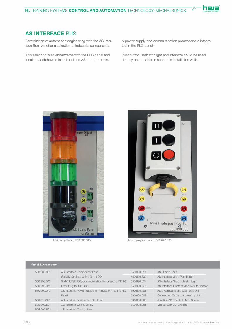
AS INTERFACE BUSFor trainings of automation engineering with the AS Inter-face Bus we offer a selection of industrial components.
This selection is an enhancement to the PLC panel and ideal to teach how to install and use AS-I components.
A power supply and communication processor are integra-ted in the PLC panel.
Pushbutton, indicator light and interface could be used directly on the table or hooked in installation walls.
AS-Interface Component Panel
(8x M12 Sockets with 4 DI + 4 DO)
SIMATIC S7/300, Communication Processor CP343-2
Front Plug for CP343-2
AS-Interface Power Supply for integration into the PLC
Panel
AS-Interface Adapter for PLC Panel
AS-Interface Cable, yellow
AS-Interface Cable, black
Panel & Accessory
AS-i Lamp Panel
AS-Interface 3fold Pushbutton
AS-Interface 3fold Indicator Light
AS-Interface Contact Module with Sensor
AS-i, Adressing and Diagnosis Unit
Connecting Cable to Adressing Unit
Junction AS-i Cable to M12 Socket
Manual with CD, English
AS-i Lamp Panel, 550.090.310 AS-i triple pushbutton, 550.090.330
550.900.001
550.990.070
550.990.071
550.990.072
550.011.007
505.900.501
505.900.502
550.090.310
550.090.330
550.990.074
550.990.075
590.600.001
590.600.002
590.600.003
550.908.001
567www.hera.de | technical details are subject to change without notice ©2015
16. TRAINING SYSTEMS CONTROL AND AUTOMATION TECHNOLOGY, MECHATRONICS
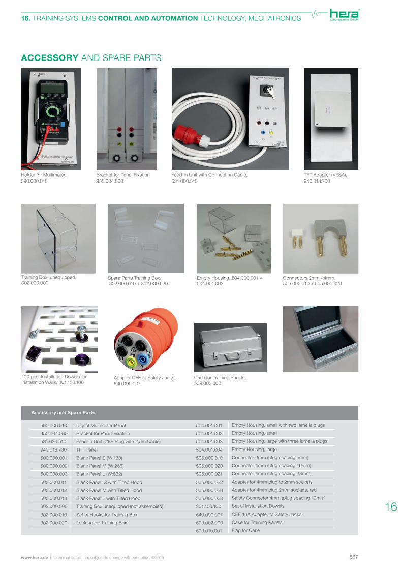
Feed-In Unit with Connecting Cable, 531.000.510
ACCESSORY AND SPARE PARTS
TFT Adapter (VESA),940.018.700
Bracket for Panel Fixation 950.004.000
Holder for Multimeter, 590.000.010
Connectors 2mm / 4mm,505.000.010 + 505.000.020
Empty Housing, 504.000.001 + 504.001.003
Spare Parts Training Box, 302.000.010 + 302.000.020
Training Box, unequipped,302.000.000
Case for Training Panels,509.002.000
Adapter CEE to Safety Jacks, 540.099.007
100 pcs. Installation Dowels for Installation Walls, 301.150.100
Empty Housing, small with two lamella plugs
Empty Housing, small
Empty Housing, large with three lamella plugs
Empty Housing, large
Connector 2mm (plug spacing 5mm)
Connector 4mm (plug spacing 19mm)
Connector 4mm (plug spacing 38mm)
Adapter for 4mm plug to 2mm sockets
Adapter for 4mm plug 2mm sockets, red
Safety Connector 4mm (plug spacing 19mm)
Set of Installation Dowels
CEE 16A Adapter to Safety Jacks
Case for Training Panels
Flap for Case
Digital Multimeter Panel
Bracket for Panel Fixation
Feed-In Unit (CEE Plug with 2,5m Cable)
TFT Panel
Blank Panel S (W:133)
Blank Panel M (W:266)
Blank Panel L (W:532)
Blank Panel S with Tilted Hood
Blank Panel M with Tilted Hood
Blank Panel L with Tilted Hood
Training Box unequipped (not assembled)
Set of Hooks for Training Box
Locking for Training Box
Accessory and Spare Parts
590.000.010
950.004.000
531.020.510
940.018.700
500.000.001
500.000.002
500.000.003
500.000.011
500.000.012
500.000.013
302.000.000
302.000.010
302.000.020
504.001.001
504.001.002
504.001.003
504.001.004
505.000.010
505.000.020
505.000.021
505.000.022
505.000.023
505.000.030
301.150.100
540.099.007
509.002.000
509.010.001
16
568 technical details are subject to change without notice ©2015 | www.hera.de
16. TRAINING SYSTEMS CONTROL AND AUTOMATION TECHNOLOGY, MECHATRONICS
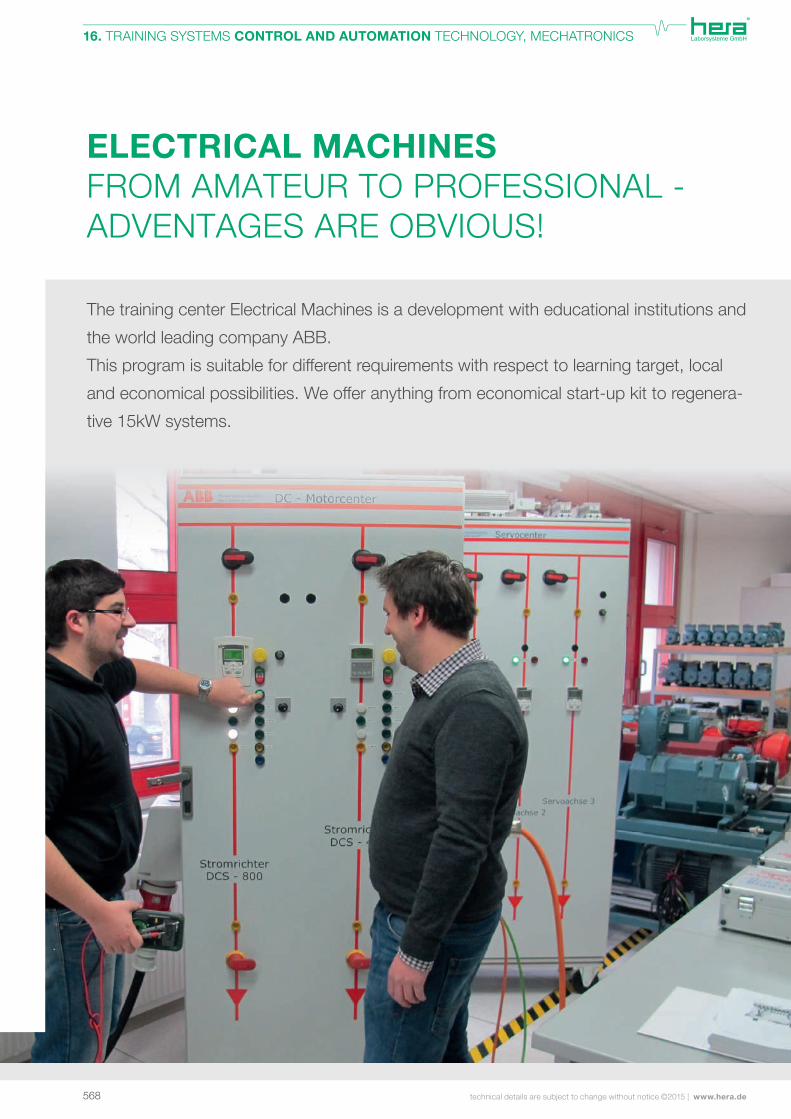
The training center Electrical Machines is a development with educational institutions and
the world leading company ABB.
This program is suitable for different requirements with respect to learning target, local
and economical possibilities. We offer anything from economical start-up kit to regenera-
tive 15kW systems.
ELECTRICAL MACHINES FROM AMATEUR TO PROFESSIONAL -ADVENTAGES ARE OBVIOUS!
569www.hera.de | technical details are subject to change without notice ©2015
16. TRAINING SYSTEMS CONTROL AND AUTOMATION TECHNOLOGY, MECHATRONICS
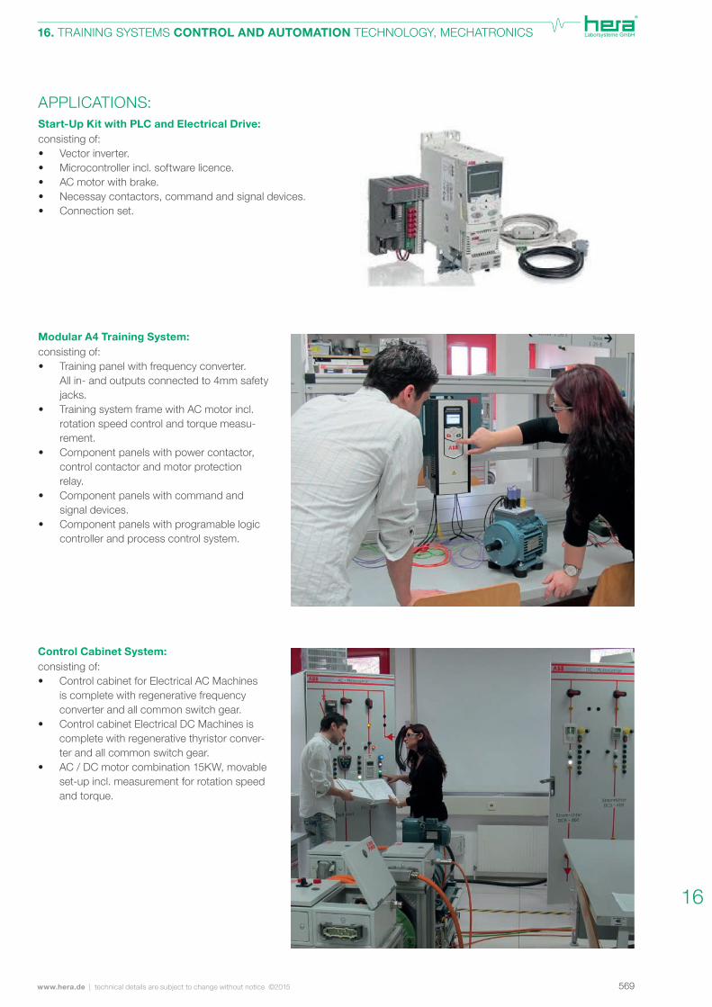
Control Cabinet System:consisting of:• Control cabinet for Electrical AC Machines
is complete with regenerative frequency converter and all common switch gear.
• Control cabinet Electrical DC Machines is complete with regenerative thyristor conver-ter and all common switch gear.
• AC / DC motor combination 15KW, movable set-up incl. measurement for rotation speed and torque.
Modular A4 Training System:consisting of:• Training panel with frequency converter.
All in- and outputs connected to 4mm safety jacks.
• Training system frame with AC motor incl. rotation speed control and torque measu-rement.
• Component panels with power contactor, control contactor and motor protection relay.
• Component panels with command and signal devices.
• Component panels with programable logic controller and process control system.
Start-Up Kit with PLC and Electrical Drive:consisting of:• Vector inverter. • Microcontroller incl. software licence. • AC motor with brake.• Necessay contactors, command and signal devices.• Connection set.
APPLICATIONS:
16

570 technical details are subject to change without notice ©2015 | www.hera.de
16. TRAINING SYSTEMS CONTROL AND AUTOMATION TECHNOLOGY, MECHATRONICS
PERFECT SIMULATIONFROM 3D PLANNING TO START-UP
What are the requirements on a modern manufacturing line? What com-
ponents are needed and how do I get things working? These and many
others are the questions that students of automation engineering have to
dealwitheveryday.Seeourpossibilitiesforyourindividualhigh-efficiency
training system on the following pages.
571www.hera.de | technical details are subject to change without notice ©2015
16. TRAINING SYSTEMS CONTROL AND AUTOMATION TECHNOLOGY, MECHATRONICS
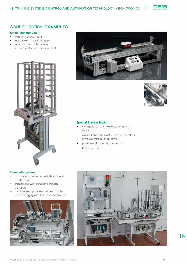
CONFIGURATION EXAMPLESSingle Transfer Line:• with DC - or AC motor• inductive end position sensor• encoding disk with counter for path and speed measurement
Complete System:• component magazine, test stations and stacker rack• transfer line with curve and transfer cunction• modular set-up on mechatronic mobles with training system Frame for control unit
Special Stacker Rack:• storage for 24 workpiece carrieres on 4
racks
• distribution by horizontal linear drive, rotary drive and vertical linear drive
• positioning is done by reed sensor
• PLC controlled
16
572 technical details are subject to change without notice ©2015 | www.hera.de
16. TRAINING SYSTEMS CONTROL AND AUTOMATION TECHNOLOGY, MECHATRONICS
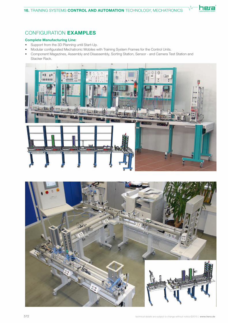
CONFIGURATION EXAMPLESComplete Manufacturing Line:• Support from the 3D Planning until Start-Up.• ModularconfiguratedMechatronicMobileswithTrainingSystemFramesfortheControlUnits. • Component Magazines, Assembly and Disassembly, Sorting Station, Sensor - and Camera Test Station and Stacker Rack.
573www.hera.de | technical details are subject to change without notice ©2015
16. TRAINING SYSTEMS CONTROL AND AUTOMATION TECHNOLOGY, MECHATRONICS
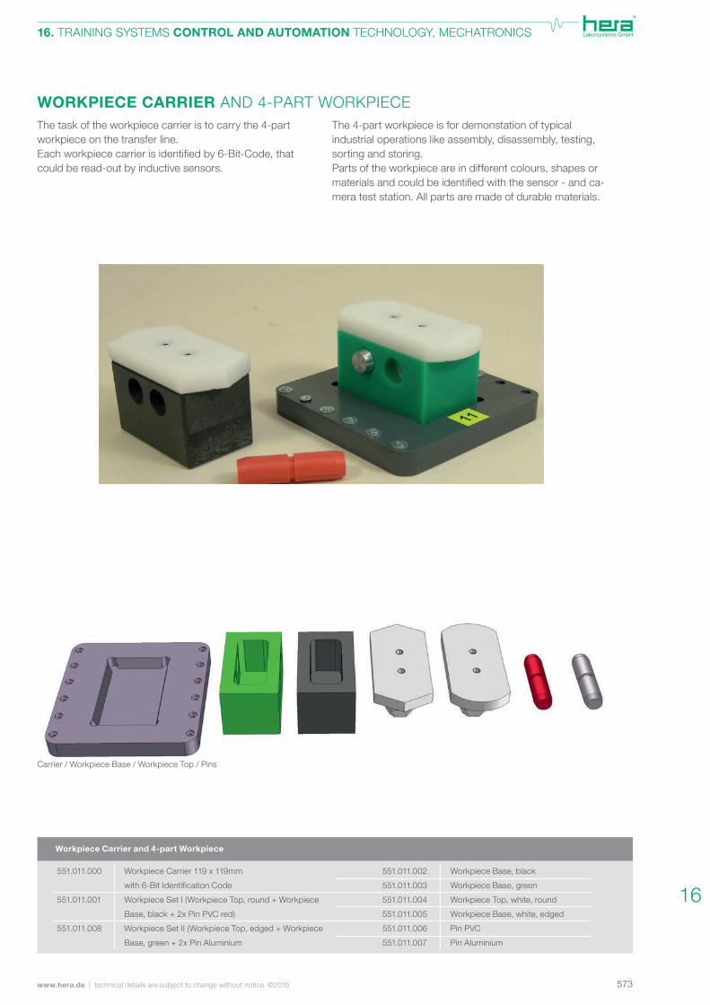
WORKPIECE CARRIER AND 4-PART WORKPIECEThe 4-part workpiece is for demonstation of typical industrial operations like assembly, disassembly, testing, sorting and storing.Parts of the workpiece are in different colours, shapes or materialsandcouldbeidentifiedwiththesensor-andca-mera test station. All parts are made of durable materials.
The task of the workpiece carrier is to carry the 4-part workpiece on the transfer line. Eachworkpiececarrierisidentifiedby6-Bit-Code,thatcould be read-out by inductive sensors.
Carrier / Workpiece Base / Workpiece Top / Pins
Workpiece Carrier and 4-part Workpiece
Workpiece Carrier 119 x 119mm
with 6-Bit Identification Code
Workpiece Set I (Workpiece Top, round + Workpiece
Base, black + 2x Pin PVC red)
Workpiece Set II (Workpiece Top, edged + Workpiece
Base, green + 2x Pin Aluminium
Workpiece Base, black
Workpiece Base, green
Workpiece Top, white, round
Workpiece Base, white, edged
Pin PVC
Pin Aluminium
551.011.000
551.011.001
551.011.008
551.011.002
551.011.003
551.011.004
551.011.005
551.011.006
551.011.007
16
574 technical details are subject to change without notice ©2015 | www.hera.de
16. TRAINING SYSTEMS CONTROL AND AUTOMATION TECHNOLOGY, MECHATRONICS
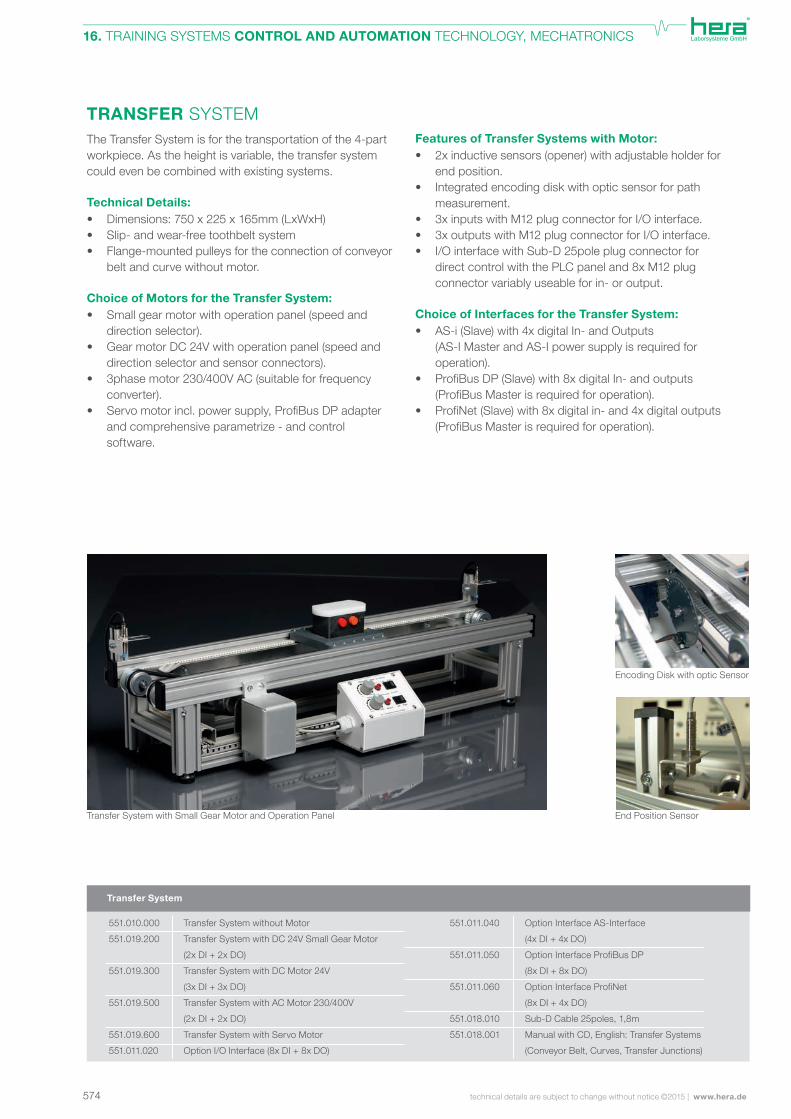
TRANSFER SYSTEMThe Transfer System is for the transportation of the 4-part workpiece. As the height is variable, the transfer system could even be combined with existing systems.
Technical Details:• Dimensions: 750 x 225 x 165mm (LxWxH) • Slip- and wear-free toothbelt system • Flange-mounted pulleys for the connection of conveyor belt and curve without motor.
Choice of Motors for the Transfer System:• Small gear motor with operation panel (speed and direction selector). • Gear motor DC 24V with operation panel (speed and direction selector and sensor connectors). • 3phase motor 230/400V AC (suitable for frequency converter). • Servomotorincl.powersupply,ProfiBusDPadapter and comprehensive parametrize - and control software.
Features of Transfer Systems with Motor:• 2x inductive sensors (opener) with adjustable holder for end position. • Integrated encoding disk with optic sensor for path measurement. • 3x inputs with M12 plug connector for I/O interface. • 3x outputs with M12 plug connector for I/O interface. • I/O interface with Sub-D 25pole plug connector for direct control with the PLC panel and 8x M12 plug connector variably useable for in- or output.
Choice of Interfaces for the Transfer System:• AS-i (Slave) with 4x digital In- and Outputs (AS-I Master and AS-I power supply is required for operation). • ProfiBusDP(Slave)with8xdigitalIn-andoutputs (ProfiBusMasterisrequiredforoperation). • ProfiNet(Slave)with8xdigitalin-and4xdigitaloutputs (ProfiBusMasterisrequiredforoperation).
Transfer System with Small Gear Motor and Operation Panel
Transfer System
Transfer System without Motor
Transfer System with DC 24V Small Gear Motor
(2x DI + 2x DO)
Transfer System with DC Motor 24V
(3x DI + 3x DO)
Transfer System with AC Motor 230/400V
(2x DI + 2x DO)
Transfer System with Servo Motor
Option I/O Interface (8x DI + 8x DO)
Option Interface AS-Interface
(4x DI + 4x DO)
Option Interface ProfiBus DP
(8x DI + 8x DO)
Option Interface ProfiNet
(8x DI + 4x DO)
Sub-D Cable 25poles, 1,8m
Manual with CD, English: Transfer Systems
(Conveyor Belt, Curves, Transfer Junctions)
551.010.000
551.019.200
551.019.300
551.019.500
551.019.600
551.011.020
551.011.040
551.011.050
551.011.060
551.018.010
551.018.001
Encoding Disk with optic Sensor
End Position Sensor
575www.hera.de | technical details are subject to change without notice ©2015
16. TRAINING SYSTEMS CONTROL AND AUTOMATION TECHNOLOGY, MECHATRONICS
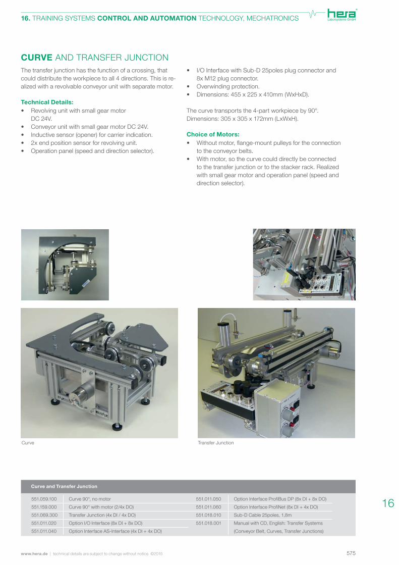
• I/O Interface with Sub-D 25poles plug connector and 8x M12 plug connector. • Overwinding protection. • Dimensions: 455 x 225 x 410mm (WxHxD).
The curve transports the 4-part workpiece by 90°.Dimensions: 305 x 305 x 172mm (LxWxH). Choice of Motors:• Withoutmotor,flange-mountpulleysfortheconnection to the conveyor belts. • With motor, so the curve could directly be connected to the transfer junction or to the stacker rack. Realized with small gear motor and operation panel (speed and direction selector).
CURVE AND TRANSFER JUNCTIONThe transfer junction has the function of a crossing, that could distribute the workpiece to all 4 directions. This is re-alized with a revolvable conveyor unit with separate motor. Technical Details:• Revolving unit with small gear motor DC 24V. • Conveyor unit with small gear motor DC 24V. • Inductive sensor (opener) for carrier indication. • 2x end position sensor for revolving unit. • Operation panel (speed and direction selector).
Option Interface ProfiBus DP (8x DI + 8x DO)
Option Interface ProfiNet (8x DI + 4x DO)
Sub-D Cable 25poles, 1,8m
Manual with CD, English: Transfer Systems
(Conveyor Belt, Curves, Transfer Junctions)
Transfer Junction
Curve 90°, no motor
Curve 90° with motor (2/4x DO)
Transfer Junction (4x DI / 4x DO)
Option I/O Interface (8x DI + 8x DO)
Option Interface AS-Interface (4x DI + 4x DO)
Curve and Transfer Junction
Curve
551.059.100
551.159.000
551.069.300
551.011.020
551.011.040
551.011.050
551.011.060
551.018.010
551.018.001
16
576 technical details are subject to change without notice ©2015 | www.hera.de
16. TRAINING SYSTEMS CONTROL AND AUTOMATION TECHNOLOGY, MECHATRONICS
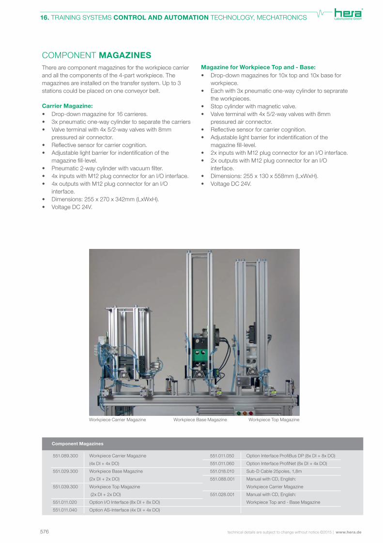
COMPONENT MAGAZINESThere are component magazines for the workpiece carrier and all the components of the 4-part workpiece. The magazines are installed on the transfer system. Up to 3 stations could be placed on one conveyor belt.
Carrier Magazine:• Drop-down magazine for 16 carrieres. • 3x pneumatic one-way cylinder to separate the carriers • Valve terminal with 4x 5/2-way valves with 8mm pressured air connector. • Reflectivesensorforcarriercognition. • Adjustablelightbarrierforindentificationofthe magazinefill-level. • Pneumatic2-waycylinderwithvacuumfilter. • 4x inputs with M12 plug connector for an I/O interface. • 4x outputs with M12 plug connector for an I/O interface. • Dimensions: 255 x 270 x 342mm (LxWxH). • Voltage DC 24V.
Magazine for Workpiece Top and - Base:• Drop-down magazines for 10x top and 10x base for workpiece. • Each with 3x pneumatic one-way cylinder to seprarate the workpieces. • Stop cylinder with magnetic valve. • Valve terminal with 4x 5/2-way valves with 8mm pressured air connector. • Reflectivesensorforcarriercognition. • Adjustablelightbarrierforindentificationofthe magazinefill-level. • 2x inputs with M12 plug connector for an I/O interface. • 2x outputs with M12 plug connector for an I/O interface.• Dimensions: 255 x 130 x 558mm (LxWxH). • Voltage DC 24V.
Workpiece Carrier Magazine
(4x DI + 4x DO)
Workpiece Base Magazine
(2x DI + 2x DO)
Workpiece Top Magazine
(2x DI + 2x DO)
Option I/O Interface (8x DI + 8x DO)
Option AS-Interface (4x DI + 4x DO)
Workpiece Carrier Magazine Workpiece Base Magazine Workpiece Top Magazine
Option Interface ProfiBus DP (8x DI + 8x DO)
Option Interface ProfiNet (8x DI + 4x DO)
Sub-D Cable 25poles, 1,8m
Manual with CD, English:
Workpiece Carrier Magazine
Manual with CD, English:
Workpiece Top and - Base Magazine
Component Magazines
551.089.300
551.029.300
551.039.300
551.011.020
551.011.040
551.011.050
551.011.060
551.018.010
551.088.001
551.028.001
577www.hera.de | technical details are subject to change without notice ©2015
16. TRAINING SYSTEMS CONTROL AND AUTOMATION TECHNOLOGY, MECHATRONICS
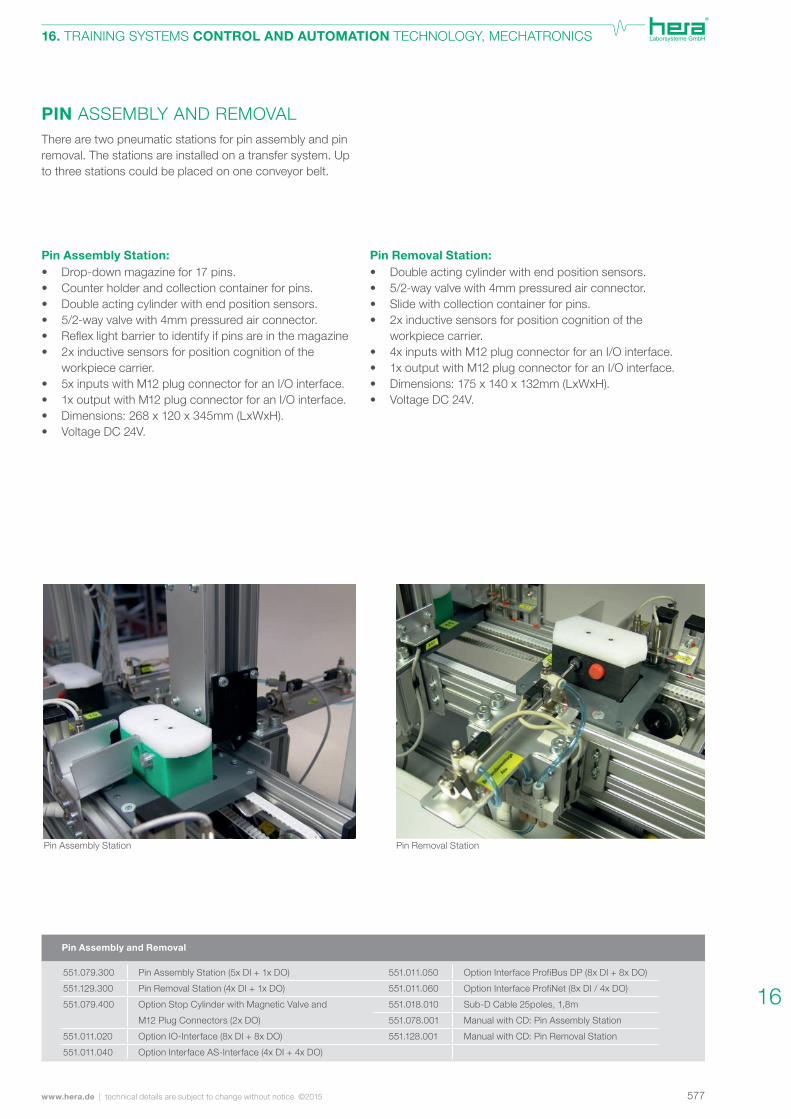
PIN ASSEMBLY AND REMOVALThere are two pneumatic stations for pin assembly and pin removal. The stations are installed on a transfer system. Up to three stations could be placed on one conveyor belt.
Pin Removal Station:• Double acting cylinder with end position sensors. • 5/2-way valve with 4mm pressured air connector. • Slide with collection container for pins. • 2x inductive sensors for position cognition of the workpiece carrier. • 4x inputs with M12 plug connector for an I/O interface. • 1x output with M12 plug connector for an I/O interface. • Dimensions: 175 x 140 x 132mm (LxWxH). • Voltage DC 24V.
Pin Assembly Station:• Drop-down magazine for 17 pins. • Counter holder and collection container for pins. • Double acting cylinder with end position sensors. • 5/2-way valve with 4mm pressured air connector. • Reflexlightbarriertoidentifyifpinsareinthemagazine• 2x inductive sensors for position cognition of the workpiece carrier. • 5x inputs with M12 plug connector for an I/O interface. • 1x output with M12 plug connector for an I/O interface.• Dimensions: 268 x 120 x 345mm (LxWxH). • Voltage DC 24V.
Pin Removal StationPin Assembly Station
Option Interface ProfiBus DP (8x DI + 8x DO)
Option Interface ProfiNet (8x DI / 4x DO)
Sub-D Cable 25poles, 1,8m
Manual with CD: Pin Assembly Station
Manual with CD: Pin Removal Station
Pin Assembly Station (5x DI + 1x DO)
Pin Removal Station (4x DI + 1x DO)
Option Stop Cylinder with Magnetic Valve and
M12 Plug Connectors (2x DO)
Option IO-Interface (8x DI + 8x DO)
Option Interface AS-Interface (4x DI + 4x DO)
Pin Assembly and Removal
551.079.300
551.129.300
551.079.400
551.011.020
551.011.040
551.011.050
551.011.060
551.018.010
551.078.001
551.128.001
16
578 technical details are subject to change without notice ©2015 | www.hera.de
16. TRAINING SYSTEMS CONTROL AND AUTOMATION TECHNOLOGY, MECHATRONICS
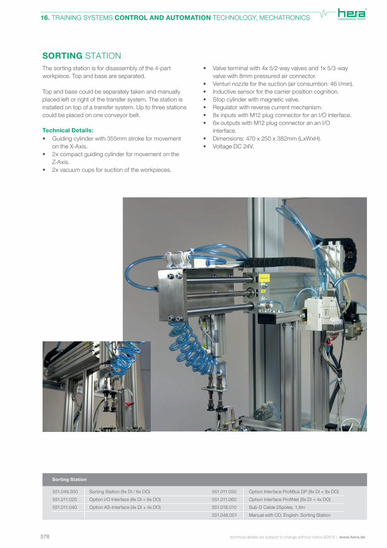
SORTING STATIONThe sorting station is for disassembly of the 4-part workpiece. Top and base are separated.
Top and base could be separately taken and manually placed left or right of the transfer system. The station is installed on top of a transfer system. Up to three stations could be placed on one conveyor belt.
Technical Details:• Guiding cylinder with 355mm stroke for movement on the X-Axis.• 2x compact guiding cylinder for movement on the Z-Axis.• 2x vacuum cups for suction of the workpieces.
• Valve terminal with 4x 5/2-way valves and 1x 5/3-way valve with 8mm pressured air connector. • Venturi nozzle for the suction (air consumtion: 46 l/min). • Inductive sensor for the carrier position cognition. • Stop cylinder with magnetic valve. • Regulator with reverse current mechanism. • 8x inputs with M12 plug connector for an I/O interface.• 6x outputs with M12 plug connector an an I/O interface.• Dimensions: 470 x 250 x 382mm (LxWxH). • Voltage DC 24V.
Sorting Station
Sorting Station (8x DI / 6x DO)
Option I/O Interface (8x DI + 8x DO)
Option AS-Interface (4x DI + 4x DO)
Option Interface ProfiBus DP (8x DI + 8x DO)
Option Interface ProfiNet (8x DI + 4x DO)
Sub-D Cable 25poles, 1,8m
Manual with CD, English: Sorting Station
551.049.300
551.011.020
551.011.040
551.011.050
551.011.060
551.018.010
551.048.001
579www.hera.de | technical details are subject to change without notice ©2015
16. TRAINING SYSTEMS CONTROL AND AUTOMATION TECHNOLOGY, MECHATRONICS
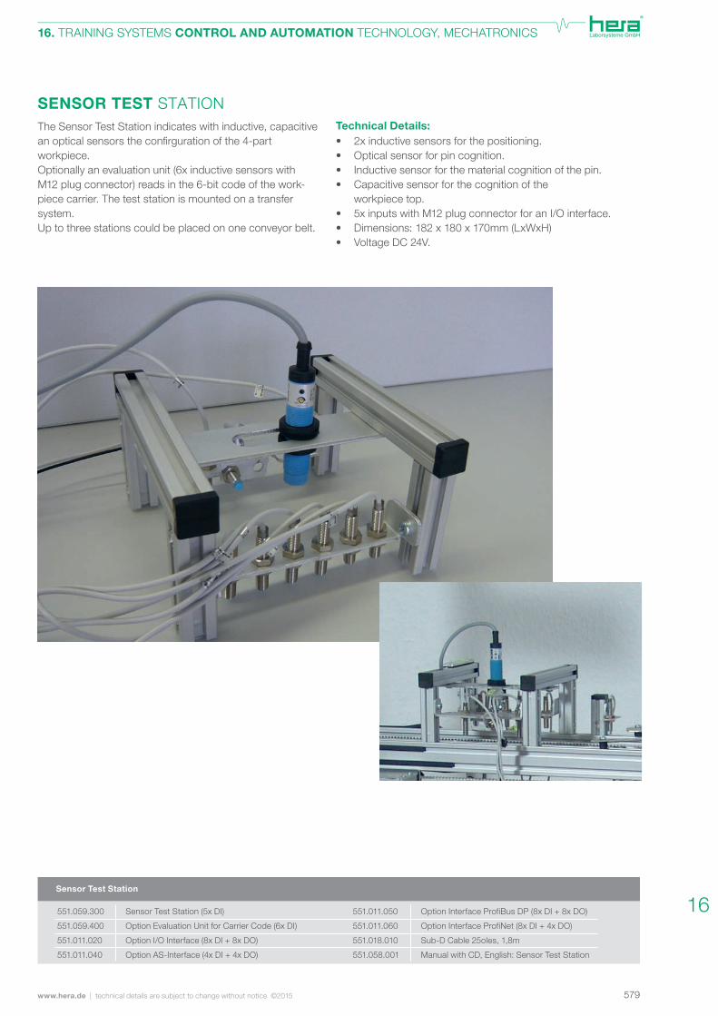
SENSOR TEST STATIONTechnical Details:• 2x inductive sensors for the positioning. • Optical sensor for pin cognition. • Inductive sensor for the material cognition of the pin. • Capacitive sensor for the cognition of the workpiece top. • 5x inputs with M12 plug connector for an I/O interface. • Dimensions: 182 x 180 x 170mm (LxWxH) • Voltage DC 24V.
The Sensor Test Station indicates with inductive, capacitive anopticalsensorstheconfirgurationofthe4-partworkpiece.Optionally an evaluation unit (6x inductive sensors with M12 plug connector) reads in the 6-bit code of the work-piece carrier. The test station is mounted on a transfer system.Up to three stations could be placed on one conveyor belt.
Sensor Test Station
Sensor Test Station (5x DI)
Option Evaluation Unit for Carrier Code (6x DI)
Option I/O Interface (8x DI + 8x DO)
Option AS-Interface (4x DI + 4x DO)
551.059.300
551.059.400
551.011.020
551.011.040
551.011.050
551.011.060
551.018.010
551.058.001
Option Interface ProfiBus DP (8x DI + 8x DO)
Option Interface ProfiNet (8x DI + 4x DO)
Sub-D Cable 25oles, 1,8m
Manual with CD, English: Sensor Test Station
16

580 technical details are subject to change without notice ©2015 | www.hera.de
16. TRAINING SYSTEMS CONTROL AND AUTOMATION TECHNOLOGY, MECHATRONICS
CAMERA TEST STATIONThis camera system enables to identify the outlines and colours of the workpiece. Thus the outline of the top (round or edged) and the colour of the pin (red or silver) could be evaluated. The software for camera installation is within the scope of delivery. Control and evaluation is done by the digital in- and outputs of the PLC.The camera test station is installed on top of a transfer system. Up to three stations could be placed on one conveyor belt.
Camera Test Features:• Outline Detection • Colour Detectoin • Colour-Matching • Greytone-Matching • Edge Detection • Corner Detection • Dimension Check • Characteristic Detection
Technical Details:• End postion sensor for test item cognition. • Camera system with adjustable holder (height, depth and tilt). • Installation software. • USB cable. • 3x inputs with M12 plug connectors for an I/O interface. • 1x output with M12 plug connectors for an I/O interface. • Dimensions: 150 x 205 x 345mm (LxWxH). • Voltage DC 24V.
Camera Test Station
Teststation Camera (3x DI + 1x DO)
Option I/O Interface (8x DI + 8x DO)
Option AS-Interface (4x DI + 4x DO)
Option Interface ProfiBus DP (8x DI + 8x DO)
Option Interface ProfiNet (8x DI + 4x DO)
Sub-D Cable 25poles, 1,8m
Manual with CD, English: Camera Test Station
551.139.310
551.011.020
551.011.040
551.011.050
551.011.060
551.018.010
551.138.001
581www.hera.de | technical details are subject to change without notice ©2015
16. TRAINING SYSTEMS CONTROL AND AUTOMATION TECHNOLOGY, MECHATRONICS
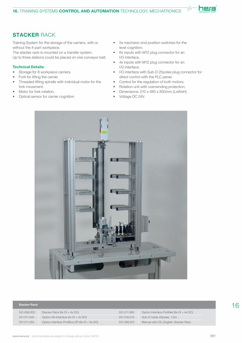
STACKER RACK• 5x mechanic end position switches for the level cognition. • 6x inputs with M12 plug connector for an I/O interface.• 4x inputs with M12 plug connector for an I/O interface. • I/O interface with Sub-D 25poles plug connector for direct control with the PLC panel. • Control for the regulation of both motors. • Rotation unit with overwinding protection. • Dimensions: 210 x 485 x 850mm (LxWxH). • Voltage DC 24V.
Training System for the storage of the carriers, with or without the 4-part workpiece.The stacker rack is mounted on a transfer system.Up to three stations could be placed on one conveyor belt. Technical Details:• Storage for 8 workpiece carriers. • Fork for lifting the carrier. • Threaded lifting spindle with individual motor for the fork movement. • Motor for fork rotation. • Optical sensor for carrier cognition.
Stacker Rack
Stacker Rack (6x DI + 4x DO)
Option AS-Interface (4x DI + 4x DO)
Option Interface ProfiBus DP (8x DI + 8x DO)
Option Interface ProfiNet (8x DI + 4x DO)
Sub-D Cable 25poles, 1,8m
Manual with CD, English: Stacker Rack
551.099.300
551.011.040
551.011.050
551.011.060
551.018.010
551.098.001
16
582 technical details are subject to change without notice ©2015 | www.hera.de
16. TRAINING SYSTEMS CONTROL AND AUTOMATION TECHNOLOGY, MECHATRONICS
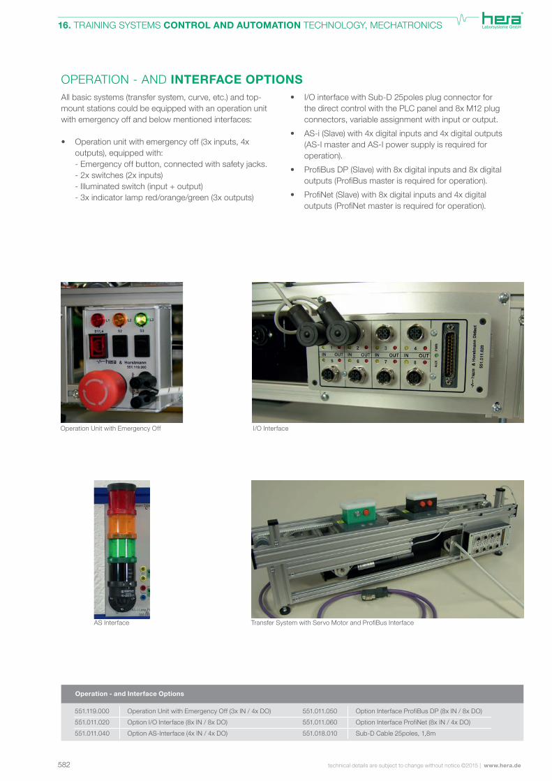
OPERATION - AND INTERFACE OPTIONSAll basic systems (transfer system, curve, etc.) and top-mount stations could be equipped with an operation unit with emergency off and below mentioned interfaces:
• Operation unit with emergency off (3x inputs, 4x outputs), equipped with: - Emergency off button, connected with safety jacks. - 2x switches (2x inputs) - Illuminated switch (input + output) - 3x indicator lamp red/orange/green (3x outputs)
• I/O interface with Sub-D 25poles plug connector for the direct control with the PLC panel and 8x M12 plug connectors, variable assignment with input or output.
• AS-i (Slave) with 4x digital inputs and 4x digital outputs (AS-I master and AS-I power supply is required for operation).
• ProfiBusDP(Slave)with8xdigitalinputsand8xdigital outputs(ProfiBusmasterisrequiredforoperation).
• ProfiNet(Slave)with8xdigitalinputsand4xdigital outputs(ProfiNetmasterisrequiredforoperation).
Operation Unit with Emergency Off
TransferSystemwithServoMotorandProfiBusInterface
Operation - and Interface Options
Operation Unit with Emergency Off (3x IN / 4x DO)
Option I/O Interface (8x IN / 8x DO)
Option AS-Interface (4x IN / 4x DO)
Option Interface ProfiBus DP (8x IN / 8x DO)
Option Interface ProfiNet (8x IN / 4x DO)
Sub-D Cable 25poles, 1,8m
551.119.000
551.011.020
551.011.040
551.011.050
551.011.060
551.018.010
I/O Interface
AS Interface
583www.hera.de | technical details are subject to change without notice ©2015
16. TRAINING SYSTEMS CONTROL AND AUTOMATION TECHNOLOGY, MECHATRONICS
Workpiece Carrier with 6-Bit Identification Code
Workpiece Set I
Workpiece Set II
551.011.000
551.011.001
551.011.008
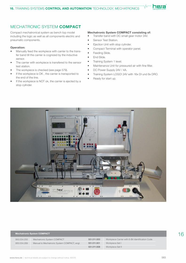
Mechatronic System COMPACT consisting of:• Transfer band with DC small gear motor 24V.• Sensor Test Station.• Ejection Unit with stop cylinder.• Compact Terminal with operator panel.• Feeding Slide.• End Slide.• Training System 1 level.• MaintenanceUnitforpressuredairwithfinefilter.• DC Power Supply 24V / 4A.• Training System LOGO! 24V with 16x DI und 8x DRO.• Ready for start up.
Compact mechatronical system as bench top model including the logic as well as all components electric and pneumatic components.
Operation:• Manually feed the workpiece with carrier to the trans-
fer band till the carrier is cognized by the inductive sensor.
• The carrier with workpiece is transfered to the sensor test station.
• The workpiece is checked (see page 579).• If the workpiece is OK , the carrier is transported to
the end of the line.• If the workpiece is NOT ok, the carrier is ejected by a
stop cylinder.
MECHATRONIC SYSTEM COMPACT
551.011.000
551.011.001
551.011.008
Mechatronic System COMPACT
Mechatronic System COMPACT
Manual to Mechatronic System COMPACT, engl.
950.034.200
950.034.289
16

584 technical details are subject to change without notice ©2015 | www.hera.de
16. TRAINING SYSTEMS CONTROL AND AUTOMATION TECHNOLOGY, MECHATRONICS
ACCESSORY MECHATRONICSFor mobile applications, all basic systems (transfer system, curves, transfer junctions and stacker rack) could be ins-talled on special mechatonic mobiles with adapting connections. Adventages:• Clear,flexibleandsafecablerunsduetospacious cabletraywithdoublerubber-lipflap.• Modularconfigurableandconnectibletoindividual systems. • Could be equipped with training system frames to hook in DIN-A4 training systems (like PLC panel, etc.). • Compatible to the laboratory system PROFI.
Technical Details:• Dimensions: 750 x 400 x 780mm (WxDxH). • Mounting base made of sheet steel with perforation for thefixationofthebasicsystems.• Rear side with cable tray made of sheet steel with cable access to the lower - and front side. • Cableflapwithcutoutforextensionsanddouble rubber lip for bruise protection. • PROFI aluminium legs with 6 slots and cross sections.• Four swivel casters (diameter: 75mm), two with brakes. • Durable, light grey powder coating. On demand we offer suitable silent running compressors with calculated air volume and maintenance unit for compressed air for each individual set-up.
Maintenance Unit for Compressed AirTraining System Frame, 461.062.901Mechatronic Mobile, 551.000.100
Training System Frame for Mechatronic Mobile
2 levels (H: 680)
Silent Compressor for Mechatronic Systems
WITHOUT Sorting Station
Silent Compressor for Mechatronic Systems WITH
Sorting Station
Component Panel Mechatronic: Maintenance Unit
for Compressed Air
Component Panel Mechatronic: Maintenance Unit
for Compressed Air and Fine Filter
Mechatronic Mobile
Adapter Base for Curve and Transfer Junction
(incl. assembly set for the fixation to the
Mechatronic Mobile)
Set of PROFI Extensions SINGLE, height:
800mm (for Training System Frame 1 level)
Set of PROFI Extensions SINGLE, height:
1100mm (for Training System Frame 2 levels)
Training System Frame for Mechatronic Mobile
1 level (H: 360)
Accessory Mechatronic
551.000.000
551.000.100
401.008.902
401.011.902
461.061.901
461.062.901
551.990.020
551.990.010
551.990.050
551.990.060