Embed Size (px)
Citation preview

Pub No. 18-HD48D1-1A-EN
Part No. 37-7760003
September 2018
TCONT302 and 303 Installation and User Guide
Trane Touchscreen Thermostat
ALL phases of this installation must comply with NATIONAL, STATE AND LOCAL CODES
IMPORTANT — This Document is customer property and is to remain with this unit.
These instructions do not cover all variations in systems or provide for every possible contingency to be met in connection with the installation. Should further information be desired or should particular problems arise which are not covered sufficiently for the purchaser’s purposes, the matter should be referred to your installing dealer or local distributor.

Installation and User Guide
2 Part No. 37-7760003 09-2018 18-HD48D1-1A-EN
WARNING!FAILURE TO READ AND FOLLOW ALL INSTRUCTIONS CAREFULLY BEFORE INSTALLING OR OPERATING THIS CONTROL COULD CAUSE PERSONAL INJURY AND/OR PROPERTY DAMAGE.
This information is intended for use by individuals possessing adequate backgrounds of electrical, mechanical, HVAC and experience. Any attempt to repair a HVAC system may result in personal injury and/or property damage. The manufacturer or seller cannot be responsible for the interpretation of this information, nor can it assume any liability in connection with its use.
LIVE ELECTRICAL COMPONENTS!During installation, testing, servicing, and troubleshooting of this product, it may be necessary to work with live electrical components. Failure to follow all electrical safety precautions when exposed to live electrical components could result in death or serious injury.
Thermostat installation and all components of the control system shall conform to Class II circuits per the NEC code.
CAUTION!To prevent electrical shock and/or equipment damage, disconnect electric power to system at main fuse or circuit breaker box until installation is complete.
ATTENTION: MERCURY NOTICE
This product does not contain mercury. However, this product may replace a product that contains mercury.
Mercury and products containing mercury must not be discarded in household trash. Do not touch any spilled mercury. Wearing non-absorbent gloves, clean up any spilled mercury and place in a sealed container. For proper disposal of a product containing mercury or a sealed container of spilled mercury, place it in a suitable shipping container. Refer to www.thermostat-recycle.org for location to send the product containing mercury.
NOTE: Use 18-gauge color-coded thermostat cable for proper wiring. Shielded cable is not typically required.
Keep this wiring at least one foot away from large inductive loads such as Electronic Air Cleaners, motors, line starters, lighting ballasts and large distribution panels. Failure to follow these wiring practices may introduce electrical interference (noise) which can cause erratic system operation.
All unused thermostat wire to be grounded at indoor unit chassis ground only. Shielded cable may be required if the above wiring guidelines cannot be met. Ground only one end of the shield to the system chassis.
1. Safety ............................................................................................22. Product Specifications ................................................................33. General Information ....................................................................3
3.1 Overview .........................................................................33.2 Contents .........................................................................33.3 Accessories ....................................................................3
4. Installation ...................................................................................44.1 Location ..........................................................................4
Figure 1: Placement4.2 Mounting .........................................................................44.3 Battery Location .............................................................44.4 Power Stealing Switch ...................................................44.5 Heat/Cool Applications ..................................................5
Figure 2: Thermostat Base Plate Figure 3: Terminal Designations Single State or Multi-Stage System: Heat / Cool Systems Figure 4: Heat Pump Systems
5 Wiring Diagrams 1 or 2 Stage AC with TAM9 or TAM7 ...........................................6 1 Stage AC with TEM3, TEM4, GAT2, GAM2 ...............................6 1 or 2 Stage AC with TEM6 ..........................................................7 1 or 2 Stage AC with GAM5B ......................................................7 AC / Cooling with GAF2-S ...........................................................8 1 or 2 Stage Heat Pump with TAM9 or TAM7 .............................8 2 Stage Heat Pump with GAM5B ................................................9 1 or 2 Stage Heat Pump with Variable Speed Furnace .............9 1 or 2 Stage Heat Pump with S9V2 Furnace ...........................10 1 or 2 Stage Heat Pump with TAM4, GAM5A, GAF2-36M .......10 1 or 2 Stage Heat / Cool Pkg Unit with VSB ............................11 HP Pkg Unit with Non-Variable SB ...........................................11
1 Stage Heat Pump with GAF2-s ......................................................12Package Heat / Cool Unit ..................................................................126. Thermostat Quick Reference ....................................................137. Installer Configuration Menu ...............................................14-188. User Guide .................................................................................19
8.1 Fan Operation ...............................................................198.2 Heating ..........................................................................198.3 Humidifier Option .........................................................198.4 Emergency Mode (Heat) ..............................................198.5 Cooling ..........................................................................198.6 Cooling Dehumidification ...........................................198.7 Fan Settings .................................................................198.8 System Setting .............................................................208.9 Manual Operation (Non-Programmable Mode) ..........208.10 Manual Operation (Programmable Mode) ..................208.11 Program Override ........................................................20
9. Programming .................................................................................9.1 Setting Time and Day ...................................................209.1.1 Automatic Daylight Saving Calculation .....................209.2 Programming Tip ..........................................................209.3 Enter the Heating Program .........................................219.4 Enter the Cooling Program .........................................219.5 Automatic Schedule
10. Planning Your Program .............................................................21Worksheet for Re-Programming .............................................22
11 Wired Remote Temperature Sensing. ......................................2311.1 Averaging or Weighting Remote Sensors ..................2311.2 Dual Fuel Temperature Setpoint .................................2311.3 Blower Blance Point for Heating ................................23
Trouble Shooting ...............................................................................24
Contents
1. Safety

Trane XR302 and XR303 Touchscreen Thermostat
Part No. 37-7760003 09-2018 18-HD48D1-1A-EN 3
SPECIFICATION DESCRIPTION
Product Models TCONT302 / TCONT303
Products XR 302 / XR 303
Size 4-9/16” x 5-13/16” x 1-3/16” (HxWxD)
Configurations Heat Pump, Heat/Cool, Dual Fuel, Heat Only, Cooling Only
Maximum Number of Stages 4 Stages Heat, 2 Stages Cooling
Operating Temperature 32°F to 105°F (0 to +41°C) / 90% RH Non Condensing
Shipping Temperature Range -40 to 150°F (-90 to +65°C)
Input Power (DC) Two 1.5V AA Alkaline
Input Power (AC) 20-30 VACm NEC Class 11m 50/60 HZ
Terminal Load 1.5A per Terminal, 2.5A Maximum, all Terminals Combined
Wire Usage 18 AWG
System Modes Auto, Heating, Cooling, Off, Emergency Heat
Fan Modes Auto, On, Program
Setpoint Temperature Range 45°F to 99°F, (7 to 37°C)
Humidification Setpoint Range 5 to 50% (303 only)
Dehumidification Setpoint Range 40 TO 95% (303 only)
Indoor Temperature Display Range 32°F to 99°F
Outdoor Temperature Display Range -40°F to 140°F
Indoor Humidity Display Range 0°F to 100°F
RATED DIFFERENTIALSFast Slow
Heat (Single Stage/Multi-Stage) 0.6°F 1.5F
Cool (Single Stage/Multi-Stage) 1.2°F 1.7°F
Heat Pump 1.2°F 1.7°F
Emer Heat 0.6°F 1.7°F
THERMOSTAT APPLICATION GUIDEThermostat Configuration Options Thermostat Applications Maximum Stages Heat/Cool
Single Stage 1 No Heat Pump (SS1) Gas, Oil, Electric, Heat Only, Cool Only or Heat/Cool Systems, 2 or 3 wire Hydronic Zone (Hot Water or Steam) Systems, 24 Volt or Millivolt
1+1
Multi Stage 2 No Heat Pump (MS2) 2+2
Heat Pump 1Single Stage Compressor Heat Pump (HP1)
Single Stage Compressor Heat Pump Systems - up to 2 Stages Aux./Emergency Heat 3+1
Heat Pump 2Two Stage or Two Compressor Heat Pump (HP2)
Two Stage or Two Compressor Heat Pump systems - up to 2 Stages Aux./Emergency Heat 4+2
*On every application, 24VAC loads should be reviewed to be sure the indoor unit control power transformer is adequately sized.
2. Product Specifications
3. General Information3.1 OverviewThe 302 and 303 are programmable thermostats with 5” diagnoal, blue backlit, touchscreen displays. The 303 features a built-in humidity sensor that may be used to control a whole house humidifier (HM) and cooling dehumidification (DHM).
3.2 Contents— 1-Thermostat
— 1-Sub-base
— 2-Phillips slotted head mounting screws
— 2-Nylon Drywall Anchors
— 1-Installation Guide / User Guide
3.3 Accessories— Wired Remote Indoor Sensor ZZSENSAL0300AAA
— Wired Remote Outdoor Sensor BAYSEN30ATEMPAA
— Wall Cover Plate BAYCOVR300AA

Installation and User Guide
4 Part No. 37-7760003 09-2018 18-HD48D1-1A-EN
4. Installation4.1 LocationThe 302 and 303 is designed for installation in climate controlled living spaces. Place the unit in a central location with good circulation.
For proper temperature sensing, avoid exposing the 302 and 303 to heat radiated from lamps, sun light, fireplaces or any other radiant heat source.
Avoid locations close to windows, behind doors or alcoves with poor air circulation, adjoining outside walls, or doors that lead to the outside.
Select a location that prevents the 302 and 303 from being directly exposed to air currents from supply registers or ceiling fans.
Mount the Control on a section of interior wall that does not contain hot or cold water pipes or duct work.
FIGURE 1. PLACEMENT OF THE 302 AND 303
IncorrectPlacement
Ceiling FanNatural heatdissipationfrom the Touch Screen
OnboardThermistor5 FEET
OptimumZone
2 FEET
CorrectPlacement
Heat from the screen may be trapped within the body of the Control by an
external top-down airflow source, such as a ceiling fan.
The onboard thermistor may be biased by this heat causing the displayed indoor temperature to be elevated.
4.2 Mounting / InstallationFollow these steps to mount the 302 and 303 Control to the wall.
1. Turn OFF all power to heating and cooling equipment.
2. If an existing thermostat is being replaced:
a. Remove the existing thermostat from the wall.
b. Record color and terminal marking of each wire.
c. Disconnect the wires from the existing thermostat being careful not to allow them to fall back into the wall.
3. Pull the thermostat body off the thermostat base. Forcing or prying on the thermostat will cause damage to the unit.
4. Place base over hole in wall and mark mounting hole locations on wall using base as template. (See Fig. 1)
5. Move base out of the way. Drill mounting holes. If you are using existing mounting holes and the holes drilled are too large and do not allow you to tighten base snugly, use plastic screw anchors to secure the base.
6. Fasten base snugly to wall using mounting holes shown in Figure 1 and two mounting screws. Leveling is for appearance only and will not affect thermostat operation.
7. Connect wires to terminal block on base using appropriate wiring diagram.
8. Push excess wire into wall and plug hole with a fire resistant material (such as fiberglass insulation) to prevent drafts from affecting thermostat operation.
9. Carefully line the thermostat up with the base and snap into place.
WARNING!Thermostat installation and all components of the control system shall conform to Class II circuits per the NEC code.
4.3 Battery LocationTwo “AA” alkaline batteries are included in the thermostat at the factory with a battery tag to prevent power drainage. Remove the battery tag to engage the batteries.
To replace batteries, set system to OFF, remove thermostat from wall and install the batteries in the rear along the top of the thermostat (see Figure 2). For best results, use a premium brand “AA” alkaline battery such as Duracell® or Energizer®. If the home is going to be unoccupied for an extended period (over 3 months) and is displayed, the batteries should be replaced before leaving.
4.4 Power Stealing SwitchThe power stealing switch is set to OFF. Placing the switch in the ON position may extend battery life. Power stealing is not compatible with every furnace. Cycle the furnace and verify the inducer and/or indoor blower do not run continuously or with no call for heat. If they do, return switch to OFF position.

Part No. 37-7760003 09-2018 18-HD48D1-1A-EN 5
MountingHole
MountingHole
Place Levelacross Mounting Tabs(for appearance only)
Place Levelacross Mounting Tabs (for appearance only)
+
S
HM
-
W/E
6
DHM
Y2
O/BL
YW2
THERMOSTAT REARVIEW
2 "AA" Batteries
Power Stealing Switches
Stack PowerStealing Switch
FIGURE 2. THERMOSTAT BASE PLATE 302 / 303
+
HM
S-
W16
DHM
W2
Supplies voltage to remote temperature sensorRemote Temperature Sensor Terminals
Supplies voltage to remote temperature sensor
Whole House Humidification (HM)— 303 ONLY
Humidification Terminal, energizes on call for heat if humidity setpoint is
above room humidity. Can also be used to provide humidification
independnent of a call to heat and/or in cooling mode if Automatic Humidification is selected in Con�guration Menu item #42
Enhanced Cooling Dehumidification (DHM) —303 ONLYDe-energizes on call for Dehumidification to lower the variable speed fan speed by 20%. The DHM terminal is only used on systems with a compatible dehumidification feature that has the required terminal connection on the control module or BK terminal on indoor models with variable speed blower motors.
Y2
O/BL
Y
+
HM
S
-
W1
6
DHM
W2
COOLING DEHUMIDIFICATION, HUMIDIFICATION, AND REMOTE TEMPERATURE SENSOR TERMINALS
FIGURE 3. – TERMINAL DESIGNATIONS SINGLE STAGE OR MULTI-STAGE SYSTEM: Heat / Cool Systems
Single Stage 1(SS1)
Multi Stage 2(MS2)
System RC RH C Y Y2 W/E W2 G O/B 6 L
Call for heat
Heat mode-1ststage
Heat mode-2ndstage
No output
24 volt power for cooling
24 volt power for heating
Cool mode-2ndstage
24 volt common (optional
for system operation, required
for remote sensor)
Call for cool No Output
Cool mode-1ststage
Blower/Circulator fanenergized on a call for cool or Fan On(also energized in
heating if configuredfor Electric Heat)
InstallerConfigurationMenu selects “O” or “B” for changeoverfunction. Set
to “O” terminalenergized in Cool& Off mode. Set to “B” terminalenergized in
Heat & mergency mode
Power closedconnection forSPDT 3-wirezone valve
Fault or SystemMalfunctionIndicator for Heat Pumps
with “L” terminalconnection.
FIGURE 4. – HEAT PUMP SYSTEMS
HeatPump 1(HP1)
Heat Pump 2(HP2)
System RC RH C Y Y2 *W/E *W2 G O/B 6 L
Heat mode-2ndstage, Emergency
Mode-1st stage*Note: Dual Fuel
option de-energizes Heatmode stage 1(compressor)when auxiliary
heat is energized
Heat mode-3rdstage, Emergency
Mode-1st stage
*Note: Dual Fueloption de-
energizes Heatmode stages 1
and 2 (bothcompressors)when auxiliary
heat is energized
Heat mode-4thstage, EmergencyMode-2nd stage
*Note: Dual Fueloption de-
energizes Heatmode stages 1
and 2 (bothcompressors)when auxiliary
heat is energized
Heat mode-3rdstage, EmergencyMode-2nd stage*Note: Dual Fuel
option de-energizes Heatmode stage 1(compressor)when auxiliary
heat is energized24 volt
power for cooling
24 volt power for heating
Heat mode-2nd stage,
Cool mode-2nd stage,
(Compressor)
No Output
24 volt common (optional
for system operation, required
for remote sensor)
Heat mode-1ststage,
Cool mode-1ststage,
(Compressor)
Blower/Circulator fanenergized on a call for cool or Fan On(also energized in
heating if configuredfor Electric Heat)
InstallerConfigurationMenu selects “O” or “B” for changeoverfunction. Set
to “O” terminalenergized in Cool& Off mode. Set to “B” terminalenergized in
Heat & mergency mode
Power closedconnection forSPDT 3-wirezone valve
Fault or SystemMalfunctionIndicator for Heat Pumps
with “L” terminalconnection.

Installation and User Guide
6 Part No. 37-7760003 09-2018 18-HD48D1-1A-EN
5. Wiring Diagrams

Part No. 37-7760003 09-2018 18-HD48D1-1A-EN 7
Trane XR302 and XR303 Touchscreen Thermostat

Installation and User Guide
8 Part No. 37-7760003 09-2018 18-HD48D1-1A-EN
G
R
B
W1
O/B
L
Y2
Y
G
Rc
Rh
C
+
S
-
HM
W2
W/E
6
DHM
Optionalremote
indoor oroutdoor
wiredsensor
FOOTNOTES:1) A/TCONT302 {does not include humidi�er(HM) and dehumidi�er(DHM) terminals}
AC/Cooling with GAF2-S
ThermostatThermostat Indoor
* Caution: Do not run Outdoor/Remote sensor wires in the same bundle with HVAC wires. Also, keep away from high voltage wiring to avoid interference.
Y
B
Outdoor
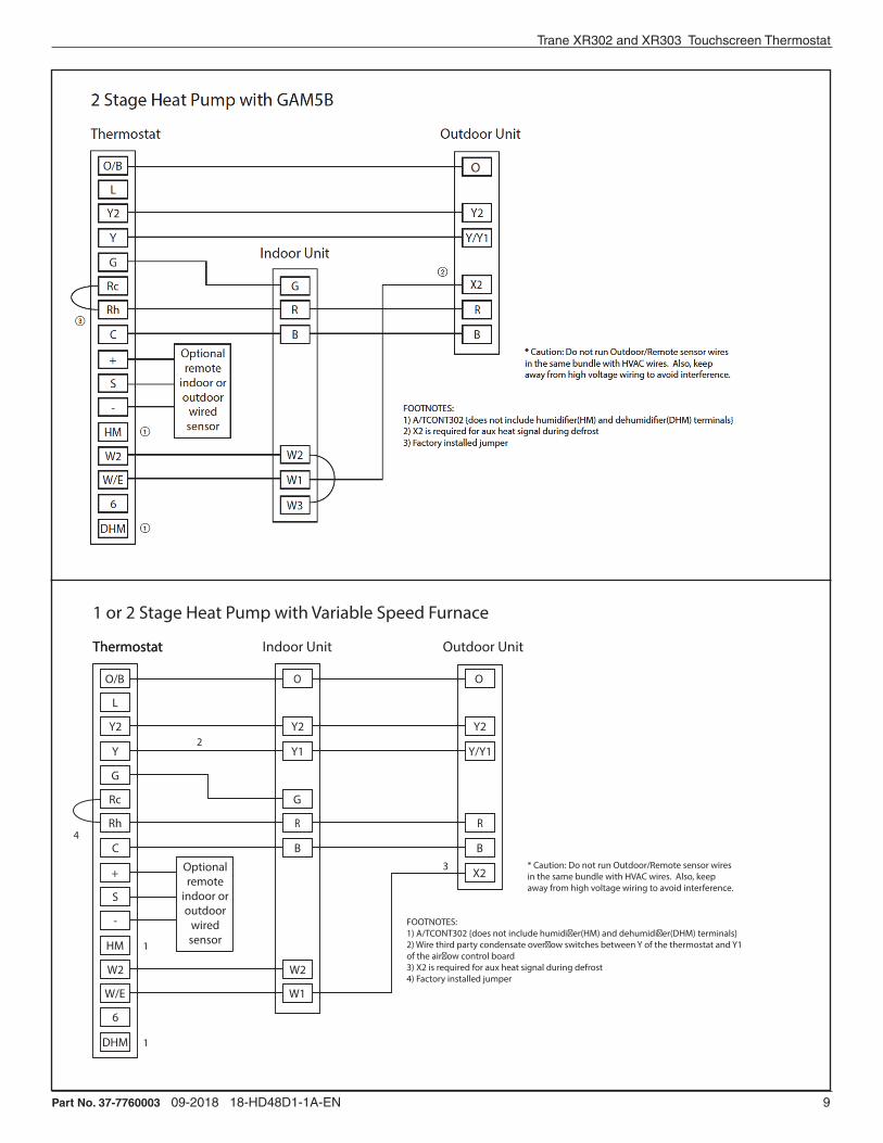
Part No. 37-7760003 09-2018 18-HD48D1-1A-EN 9
Trane XR302 and XR303 Touchscreen Thermostat
O
Y2
Y1
G
R
B
W2
W1
O
Y2
Y/Y1
R
B
X2
O/B
L
Y2
Y
G
Rc
Rh
C
+
S
-
HM
W2
W/E
6
DHM
Optionalremote
indoor oroutdoor
wiredsensor
FOOTNOTES:1) A/TCONT302 {does not include humidi�er(HM) and dehumidi�er(DHM) terminals}2) Wire third party condensate over�ow switches between Y of the thermostat and Y1 of the air�ow control board3) X2 is required for aux heat signal during defrost4) Factory installed jumper
1 or 2 Stage Heat Pump with Variable Speed Furnace
* Caution: Do not run Outdoor/Remote sensor wires in the same bundle with HVAC wires. Also, keep away from high voltage wiring to avoid interference.
ThermostatThermostat Indoor Unit Outdoor Unit
1
2
4
3
1

Installation and User Guide
10 Part No. 37-7760003 09-2018 18-HD48D1-1A-EN

Part No. 37-7760003 09-2018 18-HD48D1-1A-EN 11
Trane XR302 and XR303 Touchscreen Thermostat
G
R
B
W
O
Y/Y1
R
B
O/B
L
Y2
Y
G
Rc
Rh
C
+
S
-
HM
W2
W/E
6
DHM
X2Optionalremote
indoor oroutdoor
wiredsensor
FOOTNOTES:1) A/TCONT302 {does not include humidi�er(HM) and dehumidi�er(DHM) terminals}2) Wire third party condensate over�ow switches between Y of the thermostat and Y1 of the air�ow control board3) X2 is required to energize aux heat during defrost4) Factory installed jumper
Heat Pump with GAF2-S
Thermostat
Indoor Unit
Outdoor Unit
* Caution: Do not run Outdoor/Remote sensor wires in the same bundle with HVAC wires. Also, keep away from high voltage wiring to avoid interference.
1
1
2
4
3
G
R
B
W1
O/B
L
Y2
Y
G
Rc
Rh
C
+
S
-
HM
W2
W/E
6
DHM
Optionalremote
indoor oroutdoor
wiredsensor
FOOTNOTES:1) A/TCONT302 {does not include humidi�er(HM) and dehumidi�er(DHM) terminals}
Package Heat Cool Unit
ThermostatThermostat
* Caution: Do not run Outdoor/Remote sensor wires in the same bundle with HVAC wires. Also, keep away from high voltage wiring to avoid interference.
Y
W2

Installation and User Guide
12 Part No. 37-7760003 09-2018 18-HD48D1-1A-EN
Y2
Y1
G
R
B
W2
W1
O/B
L
Y2
Y
G
Rc
Rh
C
+
S
-
HM
W2
W/E
6
DHM
Optionalremote
indoor oroutdoor
wiredsensor
FOOTNOTES:1) A/TCONT302 {does not include humidi�er(HM) and dehumidi�er(DHM) terminals}
1 or 2 Stage Heat/Cool Package Unit with Variable Speed Blower
ThermostatThermostat Package Unit
BK
X2
Y1
G
R
B
W1
O/B
L
Y2
Y
G
Rc
Rh
C
+
S
-
HM
W2
W/E
6
DHM
Optionalremote
indoor oroutdoor
wiredsensor
FOOTNOTES:1) A/TCONT302 {does not include humidi�er(HM) and dehumidi�er(DHM) terminals}
HP Package Unit with Non-Variable Speed Blower
ThermostatThermostat Package Unit
* Caution: Do not run Outdoor/Remote sensor wires in the same bundle with HVAC wires. Also, keep away from high voltage wiring to avoid interference.
O/B
W2

Trane XR302 and XR303 Touchscreen Thermostat
Part No. 37-7760003 09-2018 18-HD48D1-1A-EN 13
6. Thermostat Quick Reference
Time of Day
Day of WeekRoomTemperature
SystemSwitch
FanSwitch
Indicates whenthermostat is callingfor Heat or Cool
Battery Level IndicatorIndicating the current power levelof the 2 “AA” batteries. Full power remaining. Half power remaining.Change The batteries should be replaced at this time.
Menu key for enteringdifferent modes such asCleaning, Configuration, SetTime and Set Schedule
Press to view Humidity setpoint
TemperatureUP/Down used formodifying setpointas well as tonavigating the menus
Set Temperature/Humidity
Note: If is displayed, thethermostat is battery powered.When battery power remainingis approximately half, willbe displayed. If the home isgoing to be unoccupied for anextended period (over 3 months)and is displayed, the batteriesshould be replaced before leaving.
Programming and Configuration Items 1. Displays and “Keypad Lockout” when in keypad lockout mode.
Displays and “Temperature Limit” and “Keypad Lockout” when limited range is activated and locked. Displays only “Temperature Limit” when limited range is activated.
2. Indicates period of day being programmed.
3. RUN SCHEDULE (run program) key.
4. SET TIME key or HOLD temperature key.
5. Displays “Change Filter”/ “Change Pad”/ “Change UV Lamp” when the system has run for the programmed filter/humidity pad/UV lamp time period as a reminder to change or clean your filter/humidity pad or to replace UV lamp.
6. COPY key or INSTALLER CONFIG key.
7. CLEAN DISPLAY key allows 30 seconds to wipe off the display or ADVANCE DAY key for programming.
8. Used in programming to set time and in configuration menu to change selections.
9. “Hold Until” indicates the time when a temporary hold period will end.
10. “Hours” and “Days” displays during steps in installer configuration.
11. The words “Hold At” are displayed when the thermostat is in the HOLD mode. “Temporary Hold At” is displayed when the thermostat is in a temporary HOLD mode.
12. “Humidity” indicates that the “Set At” display is Humidity setpoint.
13. “System On” indicates when heating or cooling stage is energized. “+2” indicates when a second stage is energized.
14. “Copy” indicates the copy program feature is being used during programming.
15. A steady “Cool Savings” display indicates the featureis enabled in the installer menu. A flashing “Cool Savings” display indicates the feature is active.
16. “Remote” indicates that the indoor remote temperature sensor, is being accessed. “Outdoor Remote” indicates the outdoor remote temperature sensor is being accessed.
17. Display time, remote temperature or humidity.
18. “Heat Pump” displays when the system configurationis set in HP1/HP2.
19. “Call for Service” indicates a fault in the heating/cooling systems. It does not indicate a fault in the thermostat.
20. Auto Schedule key for Auto Schedule function or Humidity key to display current Humidity and Humidity setpoint.
21. In Configuration Menu, shows screen number.
7
15
6 5
1 2 3 4 5 6 7 8 9 10
11
12
13
14
15
16
17
18
19
20
21
22
23
24
25
26
27
28
29
30
31
32
33
34
35
36
37
38
39
3
20
21
2
1
11 121016 17
9
8
18
14
13
419

14 Part No. 37-7760003 09-2018 18-HD48D1-1A-EN
Screen Reference Numbers for the 02 and 303 Touchscreen Thermostat
7. Installer Configuration Menu
From the Home Screen: Press Menu, then the Installer Config touch key and hold for 5 seconds. The Screen Reference number appears in the top right corner of display. See reference numbers in the table below. Screen Reference numbers appear in top right corner of display. Press to advance to the next menu item or to return to a previous menu item. Press or to change a menu item option. Shaded items are not available if selected for Non-Programmable. Write the options selected in the “Option Selected” column of the menu.
Installer Note: To default the programming, clock and Configuration Menu to the Factory Default Settings, press the , and SYSTEM keys simultaneously. The thermostat display will go blank for a few seconds, and then all segments will display momentarily. For heat pump systems, Configuration Menu items 1 and 3 must be set to match the heat pump system.
302 303 CONFIGURATION MENU
Screen Reference Number
SS1MS2
HP1HP2
Press key
Displayed Factory (Default)
Press or to select from listed options
CommentsOption
Selected
1 MS 2 HP 1, HP 2, SS 1Selects Multi-Stage (MS2, No Heat Pump), Heat Pump 1 (HP1, 1 compressor), Heat Pump 2 (HP2, 2 compress or 2 speed compressor), or Single Stage.
2 (gas) ELEGAS setting: furnace controls blower. ELE setting: thermostat controls blower.
3 0b (0) bSelects Reversing Valve (This item is only to appear if HP1 or HP2 is selected above.)
4 Days, (7) P 5 or 0Programs per week. (7 days, 5+1+1 days or non-programmable)
5 (4) PS 2
Programs per day. 4 = Morning, Day, Evening, Night 2 = Day, NightNot available if 4 is 0
6
Cool-Off-Heat-Auto
Cool-Off-Heat, Heat Off, Heat, Cool-Off,
Auto OffSystem switch configuration in non heat pump mode.
Cool-Off-Heat-
Em-AutoCool-Off-Heat-Em,
Off-Em-AutoSystem switch configuration, heat pump mode.
7 (On) E OFFSelects Energy Management Recovery. Not available if 4 is 0
8 (FA) Heat, Cr SL Selects Adjustable Anticipation, cycle rate, Heat
9 (FA) Cool, Cr SL Selects Adjustable Anticipation, cycle rate, Cool
10 (FA) Cr/AU,
EmSL
Selects Adjustable Anticipation, cycle rate auxiliary, (This item is only to appear if HP1 or HP2 is selected above).
11 (OFF) SC ON Selects Stage Cycle Completion On (Off).
12 (OFF) CL OnCompressor Lockout. Default minimum OFF Time = 5 minutes
13 (OFF) dL On Selects Continuous Display backlight.
14 0
(Temperature)5, LO to 5, HI
Selects Adjustable Ambient Temperature Display [range -5 (LO) to +5 (HI)].
15 °F °CSelects °F/°C Display (temperature units in Fahrenheit or Celsius).
16 (On) b OFF Selects audible Beeper On/Off.
17 (On) dS OFF Selects Daylight Saving Time calculation.
18 (On) Heat, AS OFFSelects Automatic Schedule for comfort temperature Programming, heat mode. Not available if 4 is 0
19 (On) Cool, AS OFFSelects Automatic Schedule for comfort temperature Programming, cool mode. Not available if 4 is 0
20 (OFF) CS On Selects Cool Savings Feature On of Off.
21 CS Cool
Savings (3)1-2-3-4-5-6 Selects amount of Cool Savings adjustment.
22 (Off) CO On Select Compressor Optimization
23 (OFF) CA On Selects Comfort Alert Feature On or Off
24 (99) Heat, HL 62-98 TEMPERATURE LIMIT, HEAT (max. heat set point).

Part No. 37-7760003 09-2018 18-HD48D1-1A-EN 15
302 303 CONFIGURATION MENU
Screen Reference Number
SS1MS2
HP1HP2
Press key
Displayed Factory (Default)
Press or to select from listed options
CommentsOption
Selected
25 (45) Cool, LL 46-82 TEMPERATURE LIMIT, COOL (min. cool set point).
26 OFF, Keypad Lockout
L (total), P (partial), Temperature
Limit(limited temperature
range)
Selects Keypad Lockout.
28 (On) Heat, FS OFFFast second stage of heat (not available if SS1 is selected above).
29 (On) Cool, FS OFFFast second stage of cool (not available if SS1 or HP1 is selected above).
30 Remote (OFF)
On Remote temperature sensor, enable/disable.
31 Remote, In Outdoor Remote Remote temperature sensor (Indoor/Outdoor).
32 (On) LS OFFLocal temp. Sensor enable/disable (only when Indoor Remote is selected On).
33 (OFF) dF OnSelects Dual Fuel feature On or OFF (this item appears if HP1 or HP2 is selected above).
34 (35) dF -5 - 50Selects Dual Fuel setpoint (°F), dF selected On with outdoor sensor available.
35 (05) dF 0 - 09Selects Dual Fuel setpoint (°F), dF selected On with no outdoor sensor.
36 (60) Cd 0-99 Selects compressor off delay in seconds, dF selected On
37 (80) AO -5 - 79Selects Auxiliary Heat cut out temperature. This item appears if HP1 or HP2 is selected and outdoor sensor is installed and enabled.
302 303 FROM THIS POINT ON REFER TO THE SPECIFIC MODEL FOR THE CORRECT SCREEN REFERNCE NUMBER
N/A 38 (80) bP 79-20Selects Blower balance point. Selection of 80 disables this feature. This item appears if HP1 or HP2 is selected and outdoor sensor is installed and enabled.
N/A 39 (OFF) Hd on Selects Humidity Display alternate with time.
N/A 40 Humidity 00
(Room Humidity)
-20 LO20 HI
Selects Humidity Display adjustment.
N/A 41 (OFF) HR LO, HI Selects Auto Humidity reduction.
N/A 42 (OFF) AH H, C, A Selects Automatic Humidification.
N/A 43 (OFF) CH On Selects Cycle Humidifier.
N/A 44 OC (0) od, OFFSelects Optimum Comfort or Optimum Dehumidification or Off.
38 45 (OFF)
Change UV Lamp
On Selects Change UV Lamp feature.
39 46 350 Days 25-1975 Change UV Lamp duration days.
N/A 47 (OFF)
Change PadOn Selects Change Humidifier Pad feature.
N/A 48 100 Hrs 25-1975 Change Humidifier Pad duration hours.
40 49 OFF
Change FilterOn Selects Change Filter feature.
41 50 200 Hrs 25-1975 Change Filter duration hours.
1. This control can be configured for: MS2 – Multi-Stage System (2 heat/2 cool) HP1 – Heat Pump with one stage of compressor (2 heat/1 cool) HP2 – Heat Pump with two stage compressor or two compressor system, Gas or Electric backup; (Dual Fuel see screen reference number 33) (4 heat/2 cool)
SS1 – Single Stage System (3 wire zone see wiring diagrams.
2. GAS or Electric (ELE) fan operation. If the heating system requires the thermostat to energize the fan, select ELE. Select GAS if the heating system energizes the fan on a call for heat. Note: Resetting the thermostat switches the option to GAS.

Installation and User Guide
16 Part No. 37-7760003 09-2018 18-HD48D1-1A-EN
3. O/B Terminal selection – Selects the operation of the reversing valve (when item 1 is set to HP1 or HP2 only). When set to “O” the changeover valve will be energized in COOL to accommodate the majority of heat applications. If the heat pump requires the changeover valve to energize in HEAT, select “B”.
4. Programs per week – This control can be configured for 7 independent day or 5+1+1 day programming or nonprogrammable modes. Default is 7-day mode. The display indicates “7 Days” as default. Other options “5 Days” or “0 Days” can be selected. If “0 Days” is selected for non-programmable mode, the step for EMR will be skipped, as this feature will not be available in this mode.
5. Program Steps per day – Not available if configured for non-programmable. This control can be configured for 4 or 2 program steps per day. Default is “4 PS” and can be toggled between 4 PS and 2 PS.
6. System Switch Configuration (MS2/SS1) – This thermostat is configured for Heat and Cool with Auto changeover default (Cool-Off-Heat-Auto). It can be configured as Heat & Cool (Cool-Off-Heat), or Heat Only (Off-Heat), or Cool Only (Cool-Off). When the control is in heat pump configuration (HP1/HP2), the system switch configuration will have an additional mode, Em for Emergency.
7. Energy Management Recovery (EMR) – (this step is skipped if configured as non-programmable). When set to “On” causes the thermostat to start heating or cooling early to make the building temperature reach the program setpoint at the time you specify. Example: The heating program is 65°F at night and 70° at 7 AM. If the building temperature is 65°F, the difference is 5°F. Allowing 5 minutes per °F rise, the thermostat setpoint will change to 70° at 6:35 AM. Cooling allows more time per °F, because it takes longer to reach temperature.
8, 9 & 10 Cycle Rate Selection - Heat, Cool, EM The factory default setting is fast cycle (FA Cr) in all modes (Heat, Cool, Em). To change to slow cycling (SL, Cr), press touch keys or toggle between FA & SL. The cycle rates are below: Mode Med Slow Heat 0.6°F 1.5°F Cool 1.2°F 1.7°F Heat Pump 1.2°F 1.7°F Emer Heat 0.6°F 1.7°F
11. Stage Cycle Completion (SC On) will cause the thermostat to complete heating and/or cooling cycles on the highest stage engaged during the cycle. Thermostat will not reduce heating or cooling stages before the heating or cooling cycle is satisfied and all stages are turned off.
12. Select Compressor Lockout (CL) – Selecting (CL On) will cause the thermostat to wait 5 minutes between cooling cycles. This is intended to help protect the compressor from short cycling. Some of the newer compressors have a time delay built in and do not require this feature to be activated in the thermostat.Your compressor manufacturer can tell you if this lockout feature is already present in their system. When the thermostat compressor time delay is activated, it will flash the set point for up to five minutes.
13. Select Continuous Display Lighting (dL) – In low lighting conditions, display backlight improves the display contrast.
14. Select Temperature Display Adjustment 5 LO to 5 HI This allows you to adjust the room temperature display by -5°F to +5°F in 1° steps. Your thermostat was accurately calibrated at the factory, however you have the option to change the display temperature value to match the previous thermostat, if you so prefer.
15. Select °F or °C Readout – Changes the display readout to Celsius or Fahrenheit as required.
16. Select Audio Prompting (Beeper) On or Off – Factory default setting is b, On. If you wish to turn off the beeper select OFF.
17. Select Daylight Saving Time Calculation – This feature will allow the thermostat to calculate the DST automatically and apply it to the Real Time Clock display. Default is On.
18. Select Automatic Schedule – Heat Mode –
19. Select Automatic Schedule – Cool Mode – Not available if configured for non-programmable. This feature allows programming a “Comfort Temperature” into all program periods with the Auto Schedule key. When Heat AS (for Heat mode) or Cool AS (for Cool mode) is selected On, the Auto Schedule feature is ready to be set. Off indicates that the feature is not ready to be used or a “Comfort Temperature” is already set. See Auto Schedule in Programming section.
20, 21 Select Cool Savings™ – Cool Savings™ provides an energy saving temperature offset (from 1-6 degrees) under peak cooling load conditions (high outdoor temperatures). If selected on, Cool Savings™ becomes active when the air-conditioner runs for periods of longer than 20 minutes. When active, Cool Savings™ gradually offsets the indoor temperature display downward. The first 1° of adjustment will take one hour of continuous air conditioner run time with subsequent 1° adjustments occurring with each additional half hour of run time (ex for a 2° offset, the air conditioner would need to run continuously for 1 ½ hours). The offset is limited to the number of degrees you select from 1 up to 6. When an offset starts or is active, “Cool Savings” will flash on the display. The principle of this energy saving feature takes advantage of the long air conditioning run times lowering the indoor humidity allowing a slightly higher temperature to feel comfortable. As the peak load subsides, this feature also takes advantage of the air conditioner’s increased capacity under more efficient conditions to gradually reduce the offset back to zero and return control to the selected setpoint temperature. If Cool Savings is selected off, no temperature offset will occur.
22. Compressor Optimization – (Not available on earlier models) CO provides a delay in circulator fan operation after the compressor turns on or off. With CO selected ON, when the compressor turns on (for a call for heat in heat pump or a call for cool) the fan will be delayed for five seconds before turning on to allow the air to be heated or cooled. After the compressor turns off for call for cool, the fan will continue to run for 20 seconds to capture additional cooling from the system. If CO is set to OFF, there will be no delay in fan operation.

Trane XR302 and XR303 Touchscreen Thermostat
Part No. 37-7760003 09-2018 18-HD48D1-1A-EN 17
23. Comfort Alert with Active Protection – (For systems that use Comfort Alert.) Turn this feature ON to enable active protection. This allows the thermostat to identify fault codes sent by the Comfort Alert module when compressor damage is possible and react to those codes by turning the compressor off. Fault codes from the Comfort Alert module will flash on the thermostat. If a Comfort Alert module is not connected, or to disable active protection, turn this feature OFF. If a Comfort Alert module is connected and this feature is turned OFF, the thermostat will still receive and flash the fault codes from the Comfort Alert module, but the active protection will not be enabled to protect the compressor.
24. Heat Temperature Limit Range – This feature adjusts the highest setpoint temperature for heat. The default setting is 99°F. It can be changed to a setting between 62°F and 98°F. The “temperature limit” icon will be displayed to the left of your setpoint temperature when using this feature. The “temperature limit” icon will flash if an attempt is made to adjust the temperature beyond the range selected.
25. Cool Temperature Limit Range – This feature adjusts the lowest setpoint temperature for cool. The default setting is 45°F. It can be changed to a setting between 46°F and 82°F. The “temperature limit” icon will be displayed to the left of your setpoint temperature when using this feature. The “temperature limit” icon will flash if an attempt is made to adjust the temperature beyond the range selected.
26, 27. Keypad Lockout – This step allows you to select the type of lockout or limited range security required. If no lockout or limited range security is required, press to advance the menu. Three security settings are available in this menu item. Use the
or keys to select the lockout desired. Lockout selections are: “Keypad Lockout and L” = Total Lockout. Total Lockout locks all keys. “Keypad Lockout and P” = Partial Lockout. Partial Lockout allows only the or keys to operate within your set temperature limits “Temperature Limit/Keypad Lockout” prevents changing the temperature limits in the Configuration Menu. After the type of lockout is selected, press Keypad Lockout Combination Number Selection Display will read “000” “Keypad Lockout”. Skip this step and continue through the remainder of the configuration menu if you require an Air Filter Change out indicator or Humidifier Pad Change out indicator by pressing the key to advance. Return to this point when you are ready to start your selected lock-out and continue by: Pressing or keys to select your keypad lockout combination number. Note: “000” is not a valid combination choice. Record the number you select for future use. Press to exit the menu. The security feature you select will start in 10 seconds. The system key will remain active for 10 seconds to allow setting Heat, Off, Cool or Auto. To unlock the keypad, press Menu, then press Installer Config. Display will show “000” and keypad lock. Enter the code used to lock the keypad and press .
28, 29 Select Fast Second Stage, ON or OFF – Not available if configured for SS1. Selecting FA ON forces additional heat stages to come on quickly when is used to raise the temperature a few degrees above the room. Select this setting if you want the heat to increase quickly
when you manually raise the temperature. Selecting FA OFF allows the thermostat to calculate an optimal time to bring on additional stages of heat. When the is used to raise the setting above the room temperature additional heat stages may come on very quickly or very slowly (up to 30 minutes later) depending on recent system performance. Select this setting if you do not require the additional heat stages to come on quickly when you manually raise the setting and want to allow the thermostat to stage based on recent system performance. The Fast Cool feature operates the cooling stages in the same manner as Fast Heat, On or Off when the temperature is lowered below the room setting.
30. Select Remote Temperature Sensor Enabled – ON enables a remote sensor connected to thermostat and displays the sensor temperature in the clock digits. OFF (default) indicates no remote sensor connected or enabled.
31. Select Remote Sensor as Indoor or Outdoor – If 30 is enabled, select Indoor or Outdoor Remote. Default is Remote Indoor.
32. Select Local Sensor Disable – If 31 is selected Indoor, the thermostat Local Sensor can be disabled so the displayed temperature will be from the Remote Sensor. Default is On LS. To disable the Local Sensor, change selection to OFF LS.
33. Select Dual Fuel Feature (dF) – This feature is applicable only in heat pump modes (HP1, HP2). Enables (On) or disables (Off) dual fuel feature of thermostat.
34. Select Dual Fuel Temperature – With dF selected On and outdoor remote sensor available, select the outdoor temperature the thermostat will use to determine when to switch to gas heat and shut down the compressor. When the outdoor temperature falls below the selected temperature the gas heat will begin. Default is 35°, but can be set in the range of -5 to 50°. A lower setting will delay the start of gas heat allowing cooler temperature in the home.
35. Select Dual Fuel Setting – With DF selected On and no outdoor sensor, select the dF setting from 01-09. Factory default is 05. The dF setting influences when second stage comes on. The factory default creates a separation of approximately 1°F between stages. Increasing the setting decreases the separation between stages. Decreasing the value increases stage separation. This adjustment allows a small change in the operation of your heat pump system versus your auxiliary system relative to the thermostat adjustment. The higher the number the sooner the auxiliary stage energizes for better comfort. The lower the number the longer period of time before auxiliary is energized for more economy.
Note: This setting is not minutes or degrees. It is numeric setting that will influence the internal thermostat calculation for staging.
36. Select Compressor Delay (Cd) – For use with Dual Fuel System. After the auxiliary heat is turned on, the compressor(s) shut down is delayed for the time selected (in seconds). This delay is factory set to 60, but can be set in the range of 0 to 99.
37. Select Auxiliary Off (AO) – Applicable with HP1 or HP2 selected with outdoor sensor. Select the temperature that will inhibit the auxiliary heating stage. As long as the outdoor temperature is above the selected temperature, the auxiliary heat will not turn on. The default setting is 80°(disabled),

Installation and User Guide
18 Part No. 37-7760003 09-2018 18-HD48D1-1A-EN
but can be set in the range of -5 ° to 79°. Thermostat will not allow a setting at or below the (dF) dual fuel setting. If indoor temperature drops below 45° because of a possible heat pump malfunction, the thermostat will turn off the pump and switch to Auxiliary heat. “Call for Service” will display on screen. There are two ways the thermostat will return to normal heat pump operation:
• Press any key to retry the pump and erase the “call for service icon.
• When setpoint is achieved on Auxiliary, system will return to heat pump operation on next call for heat.
From this point on screen reference numbers are specific to either the 302 or the 303 model
38. (303 ONLY) Select Programmable Blower Balance Point (bP) – Applicable with HP1 or HP2 selected, dF On with outdoor sensor. Requires DHM connection from thermostat to heat pump system. This feature de-energizes the DHM terminal to operate the blower at a slower speed for first stage heat when the outdoor temperature is below the temperature selected. This circulates warmer air than the higher fan speed. The default is 80° (disabled), but can be set from 20° to 79°. Select an outdoor temperature where the air coming out of the ducts begins to feel cool and the thermostat will lower the fan speed to circulate warmer air.
39. (303 ONLY) Humidity Display (Hd) – Selecting HD On enables the display to alternately show the current time and the humidity. If HD is selected OFF, the display will not show the humidity. (See page 10 for Humidity setpoint range)
40. (303 ONLY) Adjustable Humidity Display – The display will show the ambient humidity and 00 (default). The setting can be changed from -20 and LO to 20 and HI. The displayed humidity will change as the offset is changed. In Run mode, the displayed humidity will be the ambient humidity adjusted by the setting selected.
41. (303 ONLY) Auto Humidity Reduction (HR) – This feature automatically lowers humidity setting when the outside temperature drops to prevent the interior windows/walls from reaching the dew point where water condenses on surfaces. This feature default is OFF. It can be changed to select LO (low humidity reduction) or HI. To achieve automatic humidity reduction, the thermostat lowers the humidity when furnace cycles are long. When the outside temperature rises, it increases humidity. “LO” indicates a low amount of humidity reduction.
42. (303 ONLY) Automatic Humidification (AH) – This feature if enabled allows for humidification independent of a call for heating – useful in arid climates where addition humidification in heating and/or cooling is desired. If enabled, will energize the humidifier and circulator blower (“G” terminal and the “HM” terminal) if the actual humidity is below the humidity set point. The display indicates AH. Pressing the key will cycle the display from OFF to H (feature enabled in Heat mode) to C (feature enabled in Cool mode) to A (feature enabled to Auto mode) and back to OFF.
43. (303 ONLY) Cycle Humidifier (CH) – This feature provides an option that reduces the water usage by up to 50% when a flow-through humidifier is controlled by the thermostat. It is recommended for use on flow-through humidifiers only. The display indicates CH (Cycle Humidifier) with the default
indicating OFF. Pressing the or keys will toggle the display from OFF to On and back to OFF. When CH is enabled, the humidifier will cycle to turn off for 10 minutes after it has run for 10 minutes. The blower and/or furnace will continue to run during the humidifier off period.
44. (303 ONLY) Programmable Dehumidification Optimal Comfort Mode (OC) or Optimal Dehumidification (Od) – This item can be selected to OC (Optimal Comfort mode), Od (Optimal Dehumidification), or OFF. When Optimal Comfort (OC) is enabled, this feature automatically reduces indoor humidity with a call for Cooling if humidity is 2% above humidity setpoint. Humidity is set by pressing the Humidity key when in the appropriate mode, in this case Cooling, and pressing the or keys to set desired humidity (range 40% to 95%) level followed by pressing Humidity key again. This dehumidification feature uses less energy by maintaining temperature and dehumidifying only when a call for Cooling is required. Optimal Dehumidification (Od) when enabled, this feature automatically reduces indoor humidity with a call for Cooling if humidity is 2% above setting. Humidity is set by pressing the HUMIDITY key when in the appropriate mode, in this case Cooling, and pressing the or keys to set desired humidity level followed by pressing Humidity key again. This dehumidification feature may use more energy by making dehumidification a priority initiating a call for cooling if humidity is 2% above desired setting. This feature may also over-cool the condition space by up to 3 degrees to achieve the desired humidity level. (Note: Both dehumidification modes operate in Cooling mode only with a call for cooling)
45, 46 on 303 (38/39 on 302) Change UV Lamp – This feature allows the thermostat to display the words “Change UV Lamp” (Call for Service of UV bulb) after a set time of UV bulb operation. This is a reminder to maintain your UV system at optimum level of operation. When enabled, the factory set interval for “Change UV Lamp” to be displayed is 350 days of UV bulb operation and can be adjusted in 25 day increments. This should be adjusted with respect to the bulb’s recommended maintenance schedule. When “Change UV Lamp” is displayed, you can clear it by pressing Clean Display.
47, 48 (303 ONLY) Change Humidifier Pad – This feature allows the thermostat to display the words “Change Pad” after a set time of humidifier operation. This is a reminder to maintain or clean your humidifier. The factory set interval for “Change Pad” to be displayed is 100 hours of humidifier operation. This should be adjusted with respect to the humidifier’s recommended maintenance schedule. When “Change Pad” is displayed, you can clear it by pressing Clean Display.
49, 50 on 303 (40/41 on 302) Select Change Filter Run Time – This feature allows thermostat to display “Change Filter” after a set time of blower operation. This is a reminder to change or clean your air filter. This time can be set from 25 to 1975 hours in 25 hour increments. A selection of OFF will cancel this feature. When “Change Filter” is displayed, you can clear it by pressing Clean Display. In a typical application, 200 hours of run time is approximately 30 days.

Trane XR302 and XR303 Touchscreen Thermostat
Part No. 37-7760003 09-2018 18-HD48D1-1A-EN 19
8. User Guide - Operating Your Thermostat
CAUTION!Do not allow the compressor to run unless the compressor oil heaters have been operational for 6 hours and the system has not been operational for at least 5 minutes.To Prevent compressor and/or property damage, if the outdoor temperature is below 55°F, do not operate the cooling system.
If at any time your system does not operate properly, contact a qualified service person.
8.1 Fan OperationCheck thermostat operation. If your system does not have an indoor fan, skip to Heating System.
1. Turn on power to system.
2. Press FAN key to ON position. The blower should begin to operate.
3. Press FAN key to AUTO position. The blower should stop immediately.
8.2 Heating1. Press SYSTEM key to select HEAT. If the heating system
has a standing pilot, be sure to light it.
2. Press to adjust thermostat setting to 1° above the room temperature.
3. The heating system should begin to operate if the compressor lockout time (min. OFF time of 5 minutes is met. If the minimum time is not met the setpoint temperature will flash.
4. The display should show “System On”. However, if the system configuration is set to HP1 or HP2 and setpoint temperature display is flashing, the 5 minute compressor lockout feature is operating (see Configuration menu, item 11).
5. Adjust temperature setting to 3° above room temperature. If your system configuration is set at MS2, HP1 or HP2, the auxiliary heat system should begin to operate and the display will show “System On +2”.
6. Press to adjust the thermostat below room temperature. The heating system should stop operating.
8.3 Humidifier Optional To check the humidifier when System On appears and the heating system is running press the HUMIDITY* button once. Press to adjust the humidity 2% or more above the room humidity level setpoint range. (Humidity setpoint can be adjusted from 5 to 50%.)
Hum On will appear indicating it is calling for the humidifier.1
8.4 Emergency Mode Applies only to Heat Pump SystemsEmergency Heat (System EM Position) bypasses the Heat Pump to use the heat source wired to terminal W/E, W2 on the thermostat. EM is typically used when compressor operation is
*1. If Auto Schedule is displayed instead of Humidity, Auto Schedule must be turned off in the Configuration Menu
not desired, or you prefer back-up heat only.
7. Press SYSTEM key to select EM. “EM Heat Mode” will flash on the display.
8. Press to adjust thermostat setting above room temperature. The Emergency heating system will begin to operate. The display will show “System On” flashing “EM Heat Mode” and “Heat” to indicate that the Emergency system is operating.
9. Adjust temperature setting to 3° above room temperature. Any additional stages of auxiliary heat should begin to operate and the display will show “System On +2”.
10. Press to adjust the thermostat below room temperature. The heating system should stop operating.
8.5 Cooling 1. Press SYSTEM to select “Cool”.
2. Press to adjust the thermostat setting below room temperature. The blower should come on immediately on high speed, followed by cold air circulation. The display should show “System On”. If the setpoint temperature display is flashing, the compressor lockout feature is operating (see Configuration menu, item 11).
3. Adjust temperature setting to 3° below room temperature. The second stage cooling should begin to operate and the display should show “System On +2”.
4. Press to adjust the temperature setting above room temperature. The cooling system should stop operating.
8.6 Cooling Dehumidification2
1. To check the dehumidifier when System On appears and the cooling system is running press HUMIDITY* button once. Press to adjust the humidity 2% or more below the room humidity level setpoint range. DeHum On will appear indicating it is calling for the dehumidification.
2. If the room humidity is lower than the adjustment range, press to 40% and hold it for four seconds. This will force the DeHum On for one complete cooling cycle to test the dehumidification equipment.
3. After adjusting the humidity setting the display will return to temperature in approximately 10 seconds. To switch the display back to temperature immediately after adjusting humidity setting press HUMIDITY again. 1
8.7 Choose the Fan Setting (Auto or On or Prog)
1. Fan Auto/On – Traditional Fan Settings Press Fan to select Auto or On. The most commonly used setting is Auto. Fan Auto runs the fan only when the heating or cooling system is operating. Selecting Fan On runs the fan continuously for increased air circulation or to allow additional air cleaning if the system is equipped with an Electronic Air Cleaner.
2. FAN Prog – Comfort Circulating Fan Feature Pressing FAN until FAN Prog appears activates the Comfort Circulating Fan Option. This causes the thermostat to cycle the fan on for 10 minutes and off for 20 minutes if the thermostat has not called for heat or cool during the past 60 minutes. This assures moderate air
*2. Variable Speed Blower (BK Terminal)

Installation and User Guide
20 Part No. 37-7760003 09-2018 18-HD48D1-1A-EN
circulation even when the heating and cooling equipment is not cycling.
8.8 Choose the System Setting (Cool, Off, Heat, Em, Auto)Press the SYSTEM key to select:
Cool: Thermostat controls only the cooling system.
Off: Heating and Cooling systems are off.
Heat: Thermostat controls only the heating system.
Em: Setting is available only when the thermostat is configured in HP1 or HP2 mode.
Auto: Auto Changeover is used in areas where both heating and cooling may be required on the same day. AUTO allows the thermostat to automatically select heating or cooling depending on the indoor temperature and the selected heat and cool temperatures. When using AUTO, be sure to set the Cooling temperatures more than 1° Fahrenheit higher than the heating temperature.
8.9 Manual Operation for Non-Programmable ModePress the SYSTEM key to select “Heat” or “Cool” and use the keys to adjust the temperature to your desired setting. After selecting your desired settings you can also press the SYSTEM key to select AUTO to allow the thermostat to automatically change between “Heat” and “Cool”.
8.10 Manual Operation (Bypassing the Program) Programmable ModeManual operation will bypass the program and allow you to adjust the temperature as you desire. The temperature you set in Hold will be maintained indefinitely. Press or to adjust the temperature. The HOLD key will appear. Press the HOLD key. “Hold At” will appear next to the set point temperature and the thermostat will maintain the new set point temperature until Run Schedule is pressed to resume program operation.
8.11 Program Override (Temporary Override)Press or keys to adjust the temperature. This will override the temperature setting for a (default) four hour override period. The override period can be shortened by pressing or lengthened by pressing . Program Override period can range from 15 minutes to 7 days.
Example: If you turn up the heat during the morning program, it will be automatically lowered later, when the temporary hold period ends. To cancel the temporary setting at any time and return to the program, press Run Schedule.
If the SYSTEM key is pressed to select AUTO the thermostat will change to “Heat” or “Cool”, whichever ran last. If it switches to “Heat”, but you want “Cool”, or it changes to “Cool”, but you want “Heat”, press both keys simultaneously to change to the other mode.
9. Programming9.1 Set Current Time and Day
1. Press Menu key to enter installer menu. Then press Set Time once to indicate hour & AM or PM designation in clock display.
2. Press and hold either the or touch key until you reach the correct hour and AM or PM designation.
3. Press Set Time again to display minutes only in clock display.
4. Press and hold either the or touch keys until you reach the correct minutes.
5. Press Set Time once again to display year.
6. Press either the or touch key until you reach the correct year.
7. Press Set Time once again to display month.
8. Press either the or touch key until you reach the correct month.
9. Press Set Time once again to display date of the month along with day of the week at top row (which is automatic).
10. Press and hold either the or touch key until you reach the correct day of the month and day of the week displayed at the top row.
11. Press Run Schedule once or twice to remove the key. Now the display will show the correct time and room temperature.
9.1.1 Automatic Daylight Saving CalculationThe Real Time Clock will adjust automatically for daylight savings time, in the following manner:
Increment one hour at 2 AM on the second Sunday of March and decrement one hour at 2 AM on the first Sunday of November.
The daylight saving feature can be enabled or disabled in installer configuration menu. Default is DS ON (enabled).
After entering installer configuration mode, momentarily press touch key until the display indicates dS (in actual temperature digits) and on (default – in clock digits). and keys will toggle display and operation from on to OFF.
9.2 Programming Tip: Copy Program1. When programming your thermostat, you may copy the
program from one day to another day or group of days using the Copy key. In 7 day programming mode, a day can be copied to another day or all six other days. In 5+1+1 day programming mode the weekday (Mon – Fri) program can be copied into Sat and Sun or either Sat or Sun.
2. To copy a program from one day to another:
3. In Set Schedule mode, enter the program for the day or select the day you wish to copy by pressing Advance Day.
4. Press Copy. The display will show “Copy” next to the SYSTEM key and the day of the week that will be copied.
5. Press Advance Day. The day being copied will be indicated and the other days will be flashing.
6. If you wish to copy to all days skip to next step or press Advance Day until the day you wish to copy to is flashing.
7. Press Copy. “Copy” will disappear, the day you copied from will disappear and the day (s) you copied to will be on.
8. If you wish to copy this same program into other days, press Copy and repeat steps 3, 4 and 5.
9. Press Run Schedule to return to normal operation.
10. Fill in the blank schedule provided and then: