Embed Size (px)
Citation preview

Trans-Cal Industries, Inc.
Model SSD120-(XX)A &
Model SSD120-(XX)AE (Includes Mod. 1 Data)
All Solid State
Altitude Encoder/Digitizer
Owner/Installation Manual
FAA TSO-C88a Approved
Trans-Cal Industries, Inc.
Van Nuys Airport 16141 Cohasset Street
Van Nuys, CA 91406-8916 (818) 787-1221 FAX(818)787-8916
www.trans-cal.com
6 June 2015 Document Number: 881000 Rev. E

Trans-Cal Industries, Inc. Owner/Installation Manual SSD120-(XX)A
881000 Rev. E Page 2 June 2015
Copyright Notice: This document may not be reproduced, transmitted, or copied in any form without the prior written consent of Trans-Cal Industries, Inc. The data contained herein is subject to change without notice. Trans-Cal Industries hereby grants permission to download one copy of this manual and any subsequent revision, provided that electronic or printed copy contains this complete copyright notice. Trans-Cal Industries explicitly prohibits any unauthorized commercial distribution of this manual or any revision thereto. © 2015 by Trans-Cal Industries, Inc. 16141 Cohasset Street Van Nuys, CA 91406 CAGE Code 57323 818/787-1221 FAX 818/787-8916 E-Mail: [email protected] www.trans-cal.com What’s in the Box: Qty. Part Number Description 1 ea. SSD120-(XX)A Altitude Digitizer 1 ea. 881000 Owner/Installation Manual 1 ea. DA-15S 15 Pin D-Subminiature Mating Connector 1 ea. 600016 15 Pin Connector Back Shell 1 ea. 600019 1/8 NPT Nylon tube elbow fitting 1 ea. 600020 ¼” Tube Polypropylene tee fitting
History of Revision Revision Date Description
N/C 07/98 Production release.
A 10/99 Added SL70 transponder data pg. XX.
B 12/01 Added GTX 327 transponder pg. 13. Corrected current pg. 3. Clarified calibration '3.3.3 added diagram.
C 08/04 Updated Manual in entirety.
D 08/06 Updated warranty from 40 to 42 months.
E 06/2015 Revised in entirety. Added limitations, deviations & compliance §1.3.2.

Owner/Installation Manual SSD120-(XX)A Trans-Cal Industries, Inc.
881000 Rev. E Page 3
June 2015
Table of Contents Abbreviations, Acronyms and Symbols ..................................................................................... 4 Section 1.0 Introduction ............................................................................................................. 5
1.1 Scope ............................................................................................................................... 5 1.2 Equipment Description ..................................................................................................... 5 1.3 General Specifications ..................................................................................................... 5
1.3.1 Operating Altitude ...................................................................................................... 5 1.3.2 Limitations, Deviations and Compliance ................................................................... 6 TSO/ETSO/RTCA Certification & Compliance Table ......................................................... 6 1.3.3 Accuracy .................................................................................................................... 6 1.3.4 Mechanical Characteristics ....................................................................................... 6 1.3.5 Over Range ............................................................................................................... 6
1.4 Parallel ICAO Altitude Data Port Specifications ............................................................... 6 Section 2.0 Operation ................................................................................................................ 7
2.1 General ............................................................................................................................ 7 2.2 Operating Instructions ...................................................................................................... 7
Section 3.0 Installation .............................................................................................................. 8 3.1 Mechanical Installation ..................................................................................................... 8 3.2 Electrical Installation ........................................................................................................ 8 3.3 Parallel ICAO Altitude Data Port Test Equipment ........................................................... 9
Section 4.0 Calibration and Configuration ............................................................................... 10 4.1 Calibration Overview ...................................................................................................... 10 4.2 Required Equipment Span Adjust .................................................................................. 10 4.3 Span Adjust Procedure .................................................................................................. 11 Figure 1 Altitude Digitizer Correspondence ......................................................................... 12
Section 5.0 Tables I through VII Digitizer Interconnection ...................................................... 13 Figure 2 SSD120-(XX)A 15 Pin D-Sub Connector Front View ............................................ 13
Section 6.0 Instructions for Continued Airworthiness .............................................................. 20 Section 7.0 Frequently Asked Questions ................................................................................ 20 Section 9.0 Known Compatibility Issues ................................................................................. 22
9.1 Narco AT5A, AT6A, AT-50 and AT-50A Installations and SSD120-(XX)A Mod.1 ......... 22 9.2 “Mod. 1” Installations ...................................................................................................... 22 9.3 King KT-75 ..................................................................................................................... 22 9.4 S-Tec (Collins) TDR950 ................................................................................................. 22 9.5 Trans-Cal SSD120-(XX)A Backwards Compatibility ..................................................... 22 9.6 SSD120-(XX)A Compatibility to Competitor’s Products ................................................ 23
Figure 3 Temperature vs. Warm-up Time ............................................................................... 24 Outline Drawing ....................................................................................................................... 25 Environmental Qualification Form ........................................................................................... 26 Part Number Builder ................................................................................................................ 27 Manufacturer Direct Warranty ................................................................................................. 28

Trans-Cal Industries, Inc. Owner/Installation Manual SSD120-(XX)A
881000 Rev. E Page 4 June 2015
Abbreviations, Acronyms and Symbols
A Amperes AC Advisory Circular ARINC Aeronautical Radio Incorporated ASCII American Standard for Coded Information Interchange ATCRBS Air Traffic Control Radar Beacon System bps Bits per second. CFR Code of Federal Regulations C
R Carriage Return EASA European Aviation Safety Agency EEPROM Electronically Erasable Read Only Memory EIA Electronic Industries Association ETSO European Technical Standard Order FAA Federal Aviation Administration FAR Federal Aviation Regulation ft. Distance in feet. GPS Global Positioning System H/W Hardware Hz Hertz ICAO International Civil Aviation Organization I.F.F. Identification Friend or Foe In. Hg. Inches of Mercury Kbps Kilobits per Second KHz Kilohertz L
F Line Feed LSB Least Significant Bit mA Milliamperes max. Maximum MB Millibar MHz Megahertz MFD Multi-Function Display MSL Mean Sea Level min. Minimum ms Time in milliseconds. MSB Most Significant Bit mW Milliwatt NIST National Institute of Standards and Technology oz Ounce psi Pounds per Square Inch P/N Part number RAM Random Access Memory RS Recommended Standard RTCA RTCA Inc. (Radio Technical Commission for Aeronautics) SAE Society of Automotive Engineers sec. Time in seconds. SSR Secondary Surveillance Radar S/W Software TCI Trans-Cal Industries, Inc. TIA Telecommunication Industries Association TSO Technical Standard Order Vdc Volts Direct Current VSI Vertical Speed Indicator Ω Electrical resistance measured in Ohms. ºC Temperature in degrees centigrade. ± Plus or minus. § Section

Owner/Installation Manual SSD120-(XX)A Trans-Cal Industries, Inc.
881000 Rev. E Page 5
June 2015
Section 1.0 Introduction
1.1 Scope This manual provides detailed installation, calibration and operating instructions for Trans-Cal Industries’ Model SSD120-(XX)A and SSD120-(XX)AE1 series of altitude encoder/digitizer, and applies to units with operating ceilings of 30,000 to 42,000 feet. This manual assumes use by competent, qualified avionics professionals utilizing installation methods in accordance with 14CFR and other industry accepted installation practices.
1.2 Equipment Description Approved under FAA TSO-C88a, the Model SSD120-(XX)A and SSD120-(XX)AE is an all solid-state electronic device which, when connected to an aircraft static and electrical system, converts pressure altitude information into parallel digital data. The parallel digital altitude data protocol is set forth in the ICAO International Standard for SSR Pressure Altitude Transmission. In accordance with U.S. National Standards for Common System Component Characteristics for the I.F.F. Mark X (SIF)/Air Traffic Control Radar Beacon System SIF/ATCRBS. 1.3 General Specifications This equipment has been tested and will utilize power in accordance with MIL-STD-704E for 28 Vdc systems. Operating Voltage:
Model SSD120-(XX)A Model SSD120-(XX)AE2
+12 to 30 Vdc +12 to 30 Vdc
Operating Current all models: 0.25 Amps at 14Vdc 0.27 Amps at 28Vdc
Operating Temperature: Model SSD120-(XX)A Model SSD120-(XX)AE
-20° to +70°C (-4° to +158°F) -55° to +70°C (-67° to +158°F)
Storage Temperature (non-operating) all models:
-65° to +85°C (-85° to +185°F)
Warm-up time: 0 Seconds at 20°C (68°F). See Figure 2 for
low temperature warm-up times. Weight: 10 oz.
1.3.1 Operating Altitude
Model Operating Altitude SSD120-30A( ) -1000 to +30,000 feet. SSD120-35A( ) -1000 to +35,000 feet. SSD120-42A( ) -1000 to +42,000 feet.
1 SSD120-(XX)AE Extended operating temperature range: -55° to +70°C. 2 Longer warm-up times will be experienced when operated at +12 Vdc.
Trans-Cal Industries, Inc. Owner/Installation Manual SSD120-(XX)A
881000 Rev. E Page 6 June 2015
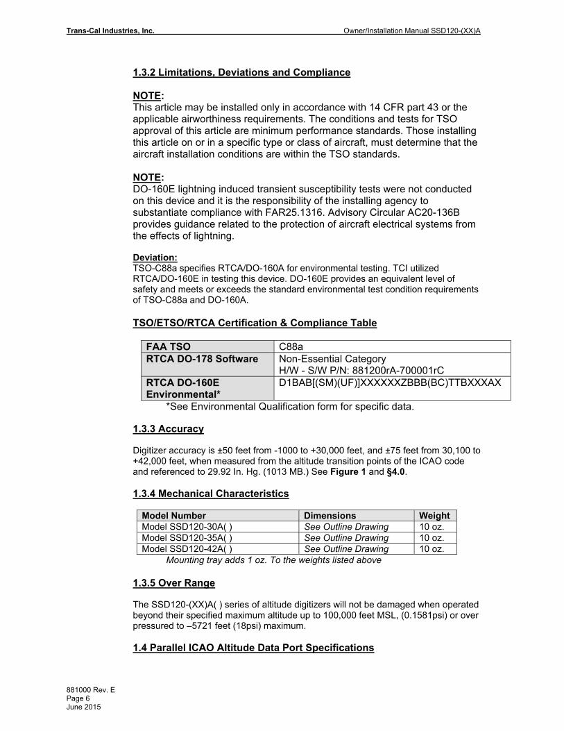
1.3.2 Limitations, Deviations and Compliance NOTE: This article may be installed only in accordance with 14 CFR part 43 or the applicable airworthiness requirements. The conditions and tests for TSO approval of this article are minimum performance standards. Those installing this article on or in a specific type or class of aircraft, must determine that the aircraft installation conditions are within the TSO standards. NOTE: DO-160E lightning induced transient susceptibility tests were not conducted on this device and it is the responsibility of the installing agency to substantiate compliance with FAR25.1316. Advisory Circular AC20-136B provides guidance related to the protection of aircraft electrical systems from the effects of lightning. Deviation: TSO-C88a specifies RTCA/DO-160A for environmental testing. TCI utilized RTCA/DO-160E in testing this device. DO-160E provides an equivalent level of safety and meets or exceeds the standard environmental test condition requirements of TSO-C88a and DO-160A. TSO/ETSO/RTCA Certification & Compliance Table
FAA TSO C88a RTCA DO-178 Software Non-Essential Category
H/W - S/W P/N: 881200rA-700001rC RTCA DO-160E Environmental*
D1BAB[(SM)(UF)]XXXXXXZBBB(BC)TTBXXXAX
*See Environmental Qualification form for specific data. 1.3.3 Accuracy Digitizer accuracy is ±50 feet from -1000 to +30,000 feet, and ±75 feet from 30,100 to +42,000 feet, when measured from the altitude transition points of the ICAO code and referenced to 29.92 In. Hg. (1013 MB.) See Figure 1 and §4.0. 1.3.4 Mechanical Characteristics
Model Number Dimensions Weight Model SSD120-30A( ) See Outline Drawing 10 oz. Model SSD120-35A( ) See Outline Drawing 10 oz. Model SSD120-42A( ) See Outline Drawing 10 oz.
Mounting tray adds 1 oz. To the weights listed above 1.3.5 Over Range The SSD120-(XX)A( ) series of altitude digitizers will not be damaged when operated beyond their specified maximum altitude up to 100,000 feet MSL, (0.1581psi) or over pressured to –5721 feet (18psi) maximum. 1.4 Parallel ICAO Altitude Data Port Specifications

Owner/Installation Manual SSD120-(XX)A Trans-Cal Industries, Inc.
881000 Rev. E Page 7
June 2015
Code Format: In accordance with U.S. National Standard for Common System Component Characteristics for the IFF Mark X (SIF) Air Traffic Control Radar Beacon System, SIF/ATCRBS. Driver Description: The parallel altitude data output is provided by the “uncommitted” collectors of a transistor array and must be “pulled-up” through a resistive load by the transponder. Pull-Up Voltage: +3 to 40Vdc. Maximum Sink Current: 35 mA. Maximum Cable Length: 4000 ft. (1219 meters) Input Signal Requirement: Pin 6 (strobe or signal common) must be either grounded or connected to the transponder.
Section 2.0 Operation
2.1 General
The SSD-120(XX)A( ) series of altitude digitizers are designed to be mounted within a pressurized or non-pressurized, but temperature controlled area within aircraft operating up to 42,000 feet MSL. Usually remotely located, the digitizer is fully automatic in operation. The parallel ICAO altitude data output is controlled by the transponder.
2.2 Operating Instructions Place the transponder in mode “C”, altitude-reporting mode. Apply power to the transponder and to the digitizer. In some installations the digitizer will automatically be supplied power when the transponder is energized; in others, power to the digitizer may be through a separate circuit breaker. If power to the digitizer is provided directly from the aircraft’s avionics buss, follow the power-up procedures recommended by the transponder manufacturer. All ICAO altitude parallel outputs will be pulled low for a self test at power up, then assume the value for the present input pressure. In some installations, the transponder controls the digitizer by enabling and disabling its output. In other installations, the digitizer’s output is not controlled by the transponder and is continuously enabled, (Digitizer pin 6 is grounded.)

Trans-Cal Industries, Inc. Owner/Installation Manual SSD120-(XX)A
881000 Rev. E Page 8 June 2015
Section 3.0 Installation 3.1 Mechanical Installation The SSD120-(XX)A should be installed in a manner consistent with the requirements of 14 CFR Part 43. Good workmanship and installation practices in accordance with the instructions given in this publication are to be observed. To verify the digitizer has been properly and safely installed, the installer should perform a visual inspection and conduct an overall operational check of the system prior to flight.
The SSD120-(XX)A( ) series of digitizer may be mounted in any attitude within the internal structure of the aircraft. DO NOT mount the digitizer in the direct air stream of either hot or cold air ducts. The mounting position should allow for a short static pressure line from the digitizer to the altimeter, access to the digitizer’s adjustments, and ample room for a service loop for the interconnecting cabling to the transponder. The SSD120-(XX)A is provided with one 1/8-27NPT static port inlet to connect the Digitizer to the aircraft static system. Apply pipe sealant (not included) or equal to the static system fitting threads. Exercise care to prevent excess sealant from plugging the inlet to the pressure sensor. On SSD120-(XX)AE devices operating below -20ºC, use metal fittings on all static line connections. The coefficient of thermal expansion for nylon is roughly three times that of aluminum. Nylon and plastic fittings will leak at low temperatures due to thermal contraction. To prevent the accumulation of condensation in the digitizer pressure sensor, locate this device away from the lowest section of the static system, and ensure a proper condensation trap and system drain is installed and functional, reference FAR 23.1325. Verify that moisture resulting from condensation will run away from the digitizer electrical connections.
Use #4-40 or #6-32 machine screws, sheet metal screws, or rivets to attach the digitizer or the mounting tray to the airframe. Secure mating connectors to the digitizer housing using the #4-40 screws provided. Refer to the outline drawing for mechanical dimensions. 3.2 Electrical Installation NOTE: Proper solder or crimp techniques should be observed when attaching wires to the mating connectors. Failure to do so could result in damage, intermittent operation or non-operation of the digitizer. Shielded cable is recommended for the wiring harness. Wire and harnesses should be installed in such a way that the weight of the cable does not exert a force on the connector pins. Harnesses must be fully supported to prevent movement and should be protected against chaffing.
CAUTION AFTER INSTALLING THE WIRING HARNESS AND BEFORE INSTALLATION OF THE DIGITIZER, A CONTINUITY CHECK OF ALL WIRES IN THE HARNESS SHOULD BE MADE TO VERIFY HARNESS CONSTRUCTION. A TEST SHOULD THEN BE MADE WITH THE AIRCRAFT POWER SUPPLIED TO THE DIGITIZER’S CONNECTOR TO VERIFY POWER, GROUND AND DATA ARE ROUTED TO THE CORRECT PINS AS DETAILED IN THE OUTLINE DRAWING. REMOVE POWER BEFORE INSTALLING THE DIGITIZER.

Owner/Installation Manual SSD120-(XX)A Trans-Cal Industries, Inc.
881000 Rev. E Page 9
June 2015
The digitizer is designed to operate with either a +14 or +28 Vdc power source. These voltages may be A+ switched power provided by the transponder or can be provided by the avionics buss. If using the avionics buss, protect the circuit with a ½ amp fuse or circuit breaker.
Parallel ICAO Altitude Data Connection The outline drawing provides electrical connector pin/function information. Use this data when connecting the digitizer to the transponder or other navigation device. In some installations where older transponders are used, the transponder may not provide an “altitude disable” function. In this case, an instrument panel mounted switch for this function may be required.
3.3 Parallel ICAO Altitude Data Port Test Equipment The output of the parallel ICAO altitude data may be monitored by any number of transponder ramp test sets, which allow display of the ICAO altitude digitizer/encoder code. The IFR Model ATC-600A Portable Transponder Test Set is one example. Alternatively, the Trans-Cal Industries’ ATS-400 may be used to display the parallel data.

Trans-Cal Industries, Inc. Owner/Installation Manual SSD120-(XX)A
881000 Rev. E Page 10 June 2015
Section 4.0 Calibration and Configuration
4.1 Calibration Overview
Reference: FAR 91.217; FAA Advisory Circular 43-6C FAR 91.411; FAR 43-Appendix E and F FAA TSO-C88a, SAE AS8003 NOTE: To ensure correspondence with all on-board pressure altitude systems, altitude digitizers that are not providing information to the ATC transponder should be tested to ensure correspondence to the primary flight altimeter, as per FAA AC43-6C.
This procedure will allow adjustment to the calibration curve of the SSD120-(XX)A or SSD120-(XX)AE as an aide in matching the digitizer output to a primary flight altimeter or NIST traceable pressure standard. The maximum allowed error between the primary flight altimeter and the altitude digitizer is ±125 feet as required by TSO-C88a. All Trans-Cal digitizers are calibrated to within ±50 feet of a NIST traceable pressure standard; however, the error allowed on altimeters at higher altitudes could lead to a combined error in excess of ±125 feet. When the altitude digitizer is installed in an aircraft for use as the transponder’s source of mode “C” information the digitizer must be recalibrated for correspondence to the aircraft’s primary flight altimeter, as required by FAR 91.217 and 91.411. Model SSD120-(XX)A and SSD120-(XX)AE are designed to be field calibrated to meet this requirement, as per the procedure described in §4.3 of this manual. The correspondence required for altitude digitizers is fully addressed in SAE Aerospace Standard AS8003 §3.11. The correspondence described by the SAE standard requires the digitizer to report altitude within ±125 feet of the primary flight altimeter’s reading when the pressure datum is set to 29.92 In. Hg., (1013 MB) absolute. The SAE standard also requires a transition accuracy of ±75 feet of the nominal transition point for that altitude. A transition is defined as the point at which the digitizer changes from one altitude to the next, either increasing or decreasing altitude. The nominal transition point of the ICAO code occurs 50 feet prior to the altitude in question. See Figure 1.
4.2 Required Equipment Span Adjust
1. Primary Flight Altimeter.
2. +12 or 28VDC power supply.
3. A pitot-static test set, capable of exercising the altimeter and digitizer over a
range of –1000 feet to the maximum altitude of the digitizer.
4. A ramp checker or test set capable of interrogating the transponder. Optional: ATS-400 or equal device which will allow the display of the 100-foot resolution parallel altitude data.

Owner/Installation Manual SSD120-(XX)A Trans-Cal Industries, Inc.
881000 Rev. E Page 11
June 2015
4.3 Span Adjust Procedure
CAUTION ALWAYS DETERMINE THE DESIGN LIMITS OF THE INSTRUMENTS ATTACHED TO THE STATIC SYSTEM. LOCATE AND IDENTIFY ALL INSTRUMENTS ATTACHED TO THE SYSTEM AND REFER TO THE MANUFACTURER’S DATA FOR MAXIMUM RATE OF CLIMB OR DESCENT, AND ANY SPECIAL TEST CONDITIONS WHICH MUST BE COMPLIED WITH TO PREVENT DAMAGE.
1. Connect the pitot-static test equipment to the aircraft’s static line, and connect
the transponder test set as per the manufacturer’s recommendations. The digitizer’s two altitude adjustment potentiometers are identified as L and H, representing low and high altitude.
Note: Changing either potentiometer will affect the other. An adjustment made to correct the low transition point, will move the high transition point, and require an adjustment of the high potentiometer.
2. Apply power to the altitude digitizer/transponder.
3. Set the primary flight altimeter barometric pressure to 29.92 In. Hg. (1013 MB).
4. Interrogate the transponder with the ramp tester, while observing the digitizer
ICAO altitude code, decrease pressure to the point where the altitude code just makes a transition to the maximum altitude encoded. Verify that the digitizer is within ±125 feet of the primary flight altimeter’s reading. If not, adjust the high potentiometer until the digitizer transition point is within ±30 feet of the nominal transition point. (i.e. while ascending, the digitizer should transition from 29,900 feet to 30,000 feet at 29,950 feet nominally.)
5. Increase pressure until the digitizer’s output just makes the transition from 100
feet to 0 feet. Verify that the altitude digitizer reports within ±125 feet of the primary flight altimeter. If not, adjust the low potentiometer until the transition point is within ±30 feet of the nominal transition point. (i.e. while descending, the digitizer should transition from +100 to 0 feet at +50 feet nominally.)
6. Repeat steps (4) and (5) until the ±125 foot tolerance is achieved for both the
maximum calibration altitude and the minimum calibration altitude.
7. Exercise the aircraft’s static system over the operating range of the altitude digitizer and, with increasing and decreasing pressure, verify at a minimum of ten test points that the altitude digitizer and primary flight altimeter correspond within the ±125 foot tolerance. Lightly tap the altimeter before each reading to eliminate friction. If correspondence is not achieved at any test point, the altimeter may require calibration.
8. Verify that the digitizer’s output is disabled when the transponder is not in mode
“C”, or when the “Altitude Disable” switch is in the off position.

Trans-Cal Industries, Inc. Owner/Installation Manual SSD120-(XX)A
881000 Rev. E Page 12 June 2015
Figure 1 Altitude Digitizer Correspondence

Owner/Installation Manual SSD120-(XX)A Trans-Cal Industries, Inc.
881000 Rev. E Page 13
June 2015
Section 5.0 Tables I through VII Digitizer Interconnection The following digitizer interconnections are provided as a quick reference only, and though they are correct to the best of our knowledge, always consult the latest installation, operation, and service bulletins from the equipment manufacturer.
Table I
SSD120 15 Pin Conn. Function
Bendix/King KT73
Pin Number
Bendix/King KT76/78
Pin Number
Bendix/King KT76A/78A Pin Number
Bendix/King KXP
Pin Number
1 D4 8 *3 *3 V
2 A1 M 6 M G
3 A2 K 7 K H
4 A4 J 9 J J
5 B1 E 4 E K
9 B2 C 1 C L
10 B4 B 2 B M
11 C1 D 3 D P
13 C2 L 8 L R
12 C4 H 10 H S
6 Output Enable
Connect to aircraft ground.
Connect to aircraft ground.
Connect to aircraft ground.
Connect to aircraft ground.
8 or 14 *4
14 to 28Vdc Input.
Connect to aircraft’s avionics buss
protected by a fuse or circuit breaker.
Connect to aircraft’s avionics buss protected
by a fuse or circuit breaker.
Connect to aircraft’s avionics buss protected
by a fuse or circuit breaker.
Connect to aircraft’s avionics buss protected
by a fuse or circuit breaker.
15 Ground Connect to
aircraft ground. Connect to aircraft
ground. Connect to aircraft
ground. Connect to aircraft
ground.
Figure 2 SSD120-(XX)A 15 Pin D-Sub Connector Front View
3 Data for this connection is not available at this time. 4 Pins 8 and 14 are connected internally.

Trans-Cal Industries, Inc. Owner/Installation Manual SSD120-(XX)A
881000 Rev. E Page 14 June 2015
Table II
SSD120 15 Pin Conn. Function
Cessna RT359A, RT459A, RT859A
Pin Number
Narco AT-150 AT-50, AT-50A
Pin Number
Narco AT-6A AT-5, AT-6
Pin Number Microair T2000
1 D4 10 *5 *5 21
2 A1 14 7 2 9
3 A2 13 6 4 10
4 A4 15 8 8 11
5 B1 19 12 9 12
9 B2 17 10 10 13
10 B4 16 9 11 17
11 C1 21 14 1 18
13 C2 18 11 3 19
12 C4 20 13 5 20
6 Output Enable 11 5 12
Connect to aircraft ground.
8 or 14 *6
14 to 28Vdc Input 9 18 13 2
15 Ground
Connect to aircraft ground.
Connect to aircraft ground. 14
Connect to aircraft ground.
Narco AT-50 and AT-50A Installations
The Narco AT-5A, AT-6A, AT-50 or AT-50A transponder will not accept data from the SSD120-(XX)A( ) Altitude Digitizer. A modification to remove the output decoupling capacitors is required. The unit may be ordered from the factory with this modification. Order Model Number SSD120-(XX)A( ) with Mod 1. Please note! The Narco AT-50 and earlier transponder models require a modification before they will function correctly with any altitude encoder. This modification is outlined in Narco Service Bulletin AT-50A-5.
5 Data for this connection is not available at this time. 6 Pins 8 and 14 are connected internally.

Owner/Installation Manual SSD120-(XX)A Trans-Cal Industries, Inc.
881000 Rev. E Page 15
June 2015
Table III
SSD120 15 Pin Conn. Function
Garmin GTX 327
Pin Number
Garmin GTX 330 & 330D
Pin Number This column left
blank intentionally. This column left
blank intentionally.
1 D4 18 11
2 A1 3 2
3 A2 5 4
4 A4 6 5
5 B1 9 7
9 B2 11 9
10 B4 12 10
11 C1 10 8
13 C2 4 3
12 C4 7 6
6 Output Enable
13 or 25 or aircraft ground 50
8 or 14 *7
14 to 28Vdc Input
14 to 28VDC Input
Pin 62 through a 3 amp 50V
reverse rated diode.
15 Ground Connect to aircraft
ground. Connect to
aircraft ground.
7 Pins 8 and 14 are connected internally.

Trans-Cal Industries, Inc. Owner/Installation Manual SSD120-(XX)A
881000 Rev. E Page 16 June 2015
Table IV
SSD120 15 Pin Conn. Function
Edo-Air RT-777
Pin Number
Genave Beta 5000
Pin Number
Collins TDR 950
Pin Number
Radair 250
Pin Number
1 D4 15 0 3 15
2 A1 7 4 12 7
3 A2 5 5 10 6
4 A4 3 6 7 13
5 B1 12 7 6 9
9 B2 13 8 5 10
10 B4 14 9 4 11
11 C1 8 10 8 14
13 C2 6 11 11 16
12 C4 4 12 9 12
6 Output Enable 2 3
Connect to aircraft ground. 19
8 or 14 *8
14 to 28Vdc Input
Connect to aircraft’s avionics buss protected by
a fuse or circuit breaker. 2
Connect to aircraft’s avionics
buss protected by a fuse or
circuit breaker. 22
15 Ground 2 Connect to aircraft
ground. Connect to
aircraft ground. Connect to
aircraft ground.
8 Pins 8 and 14 are connected together internally.

Owner/Installation Manual SSD120-(XX)A Trans-Cal Industries, Inc.
881000 Rev. E Page 17
June 2015
Table V
SSD120 15 pin Conn. Function
Bendix TPR-2060
Pin Number
Bendix TR641A/B
Pin Number
Wilcox 1014A
Pin Number
UPS AT Apollo SL70 Pin Number
1 D4 *9 N C 35
2 A1 4 A k 13
3 A2 6 B c 31
4 A4 8 C W 12
5 B1 9 D T 33
9 B2 10 E L 14
10 B4 11 F D 32
11 C1 3 H P 16
13 C2 5 J f 34
12 C4 7 K Z 15
6 Output Enable
Connect to aircraft ground.
Connect to aircraft ground.
Connect to aircraft ground.
Connect to aircraft ground.
8 or 14 *10
14 to 28Vdc Input
Connect to aircraft’s avionics buss protected by
a fuse or circuit breaker.
Connect to aircraft’s avionics
buss protected by a fuse or
circuit breaker.
Connect to aircraft’s avionics buss protected by
a fuse or circuit breaker.
Connect to aircraft’s avionics buss protected by
a fuse or circuit breaker.
15 Ground Connect to aircraft
ground. Connect to
aircraft ground. Connect to aircraft
ground. Connect to aircraft
ground.
9 Data for this connection is not available at this time. 10 Pins 8 and 14 are connected internally.

Trans-Cal Industries, Inc. Owner/Installation Manual SSD120-(XX)A
881000 Rev. E Page 18 June 2015
Table VI
SSD120 15 pin Conn. Function
Becker Avionic Systems
ATC3401 ATC2000
Becker Avionic Systems ATC4401
Terra TRT-250
TRT-250D
This column left blank
intentionally.
1 D4 23 20 9
2 A1 16 1 5
3 A2 15 2 17
4 A4 14 3 16
5 B1 17 14 15
9 B2 19 15 2
10 B4 18 16 14
11 C1 22 17 3
13 C2 21 18 4
12 C4 20 19 18
6 Output Enable 24 25 12
8 or 14*11
+14 to 28Vdc 6 6 20
15 Ground 24 25 Connect to
aircraft ground
11 Pins 8 and 14 are connected internally.

Owner/Installation Manual SSD120-(XX)A Trans-Cal Industries, Inc.
881000 Rev. E Page 19
June 2015
Table VII
SSD120 15 pin Conn. Function
Bendix/King 560EGPWS
& MK-XXI EGPWS
Bendix/King KMH 870
IHAS Processor
This column left blank
intentionally.
1 D4 No connection 18
2 A1 12 11
3 A2 52 10
4 A4 33 9
5 B1 14 14
9 B2 34 13
10 B4 73 12
11 C1 32 17
13 C2 13 16
12 C4 72 15
6 Output Enable
Connect to aircraft ground
Connect to aircraft ground
8 or 14*12
+14 to 28Vdc
Connect to avionics buss via circuit
breaker
Connect to avionics buss
via circuit breaker
15 Ground Connect to aircraft
ground Connect to
aircraft ground
12 Pins 8 and 14 are connected internally.

Trans-Cal Industries, Inc. Owner/Installation Manual SSD120-(XX)A
881000 Rev. E Page 20 June 2015
DIGITIZER PARALLEL DATA OUTPUTCIRCUIT 1 OF 10
D4 THRU C4
TYPICAL TRANSPONDER PARALLELDATA INPUT CIRCUIT 1 OF 10
D4 THRU C4
LOGICLOGIC
10K
+9Vdc
STROBE/OUTPUTENABLE
PIN 6
EMITTER
COLLECTORBASE
Section 6.0 Instructions for Continued Airworthiness
The SSD120-(XX)A is an all solid-state device and requires no periodic maintenance to maintain its airworthiness. The altitude encoder is to be tested during the aircraft biennial transponder and pitot-static system test as required by Federal Aviation Regulations. If the altitude encoder reports an error in excess of ±125 feet compared to the primary flight altimeter, than recalibration as per §4.0 of this manual is required. If the error cannot be corrected through this procedure, then the unit is to be repaired or replaced. Contact Trans-Cal Industries for further information.
Section 7.0 Frequently Asked Questions
1. How often must the Altitude Digitizer be calibrated; is there periodic maintenance required?
There is no periodic maintenance required. The Digitizer is tested and calibrated, if required, during the aircraft’s biennial certification of the transponder and static system.
2. How many devices may be driven off of the parallel ICAO Altitude data port?
The number of devices that may be connected to the Digitizer ICAO altitude output is a function of the current and power required. The Digitizer parallel data outputs are “uncommitted” collectors of a transistor array which are “pulled-up” through a resistive load by the transponder (or other device) to some positive voltage. This voltage may range from about +3 to +40Vdc. Each Digitizer data output line (i.e. D4, A1, A2, A4 etc.) is capable of providing 35 mA (0.035 Amperes) with a not to exceed power rating of 100mW (0.1 Watts), when it is “sinking” current in the “on” position. Typical modern applications require about 1 milliampere or less per data line, per device.
In the circuit illustrated below, the current is calculated as 0.9mA at 8.1mW. At this current and power rating, a total of 12 identical devices could be connected to the digitizer. Given the wide variety of input circuits capable of interfacing with the Digitizer and the possibility of crosstalk, careful planning of the electrical loads acting upon the Digitizer output is advised.
IRV = AmpsOhms
Vdc0009.010000
9=
PIV =)( WattsAmpsVdc 0081.00009.09 =×

Owner/Installation Manual SSD120-(XX)A Trans-Cal Industries, Inc.
881000 Rev. E Page 21
June 2015
DIGITIZER PARALLEL DATA OUTPUTCIRCUIT 1 OF 10
D4 THRU C4
TYPICAL ICAO PARALLEL DATAINPUT CIRCUIT 1 OF 10
D4 THRU C4
LOGICLOGIC
10K
+9Vdc
STROBE/OUTPUTENABLE
PIN 6
EMITTER
COLLECTORBASE
LOGIC
4.7K
+5Vdc
TYPICAL TRANSPONDER PARALLELDATA INPUT CIRCUIT 1 OF 10
D4 THRU C4
TYPICAL BLOCKINGDIODE 1 OF 10
D4 THRU C4
3. Why do altitude encoding errors occur when connecting a second or third device to the altitude encoder, but not when only one device is connected?
This is a symptom of “Cross-Talk.” This condition typically occurs when the devices connected to the altitude encoder are “pulling-up” to different voltages without diode isolation. When the altitude encoder is in the “off” state the data line electrical current may flow in undesired directions due to this pull-up voltage imbalance. Most modern avionics devices are diode isolated; but in applications where older equipment is mixed with new devices, blocking diodes may be required to isolate the older device. Germanium or Schottky blocking diodes are the preferred devices to install due to the low forward voltage drop across the diode. Connect as detailed in the illustration below. Use of general purpose silicon diodes are NOT recommended, as the larger voltage drop may interfere with the logic threshold detection in the equipment.
4. My transponder does not have a D2 or D4 input. What do I do with these signals from the Digitizer?
Leave unused data bits unconnected or connect to circuit ground.
5. What is the Strobe or Signal Common or Output Enable function on the ICAO altitude data port?
This is a control signal for the ICAO parallel altitude data. On devices manufactured by Trans-Cal this function is always on pin 6 of the ICAO altitude port. A “high” or “open” on this pin will disable the ICAO altitude data. A “low” or “ground” on this line will enable the altitude data. Some interconnecting devices may use this signal to control the flow of data from the Digitizer. Be aware that when using this signal and connecting multiple devices to the Digitizer, interruptions of the ICAO data will occur when the controlling device “strobes” the Digitizer.

Trans-Cal Industries, Inc. Owner/Installation Manual SSD120-(XX)A
881000 Rev. E Page 22 June 2015
Section 9.0 Known Compatibility Issues 9.1 Narco AT5A, AT6A, AT-50 and AT-50A Installations and SSD120-(XX)A Mod.1
The Narco AT-5A, AT-6A, AT-50 or AT-50A transponder will not accept data from the SSD120-(XX)A Altitude Digitizer. A modification to remove the output decoupling capacitors is required. The unit may be ordered from the factory with this modification. Order Model Number SSD120-(XX)A with Mod. 1. Please note! This modification may NOT be performed in the field. Please also note! The Narco AT-50 and earlier transponder models require a modification before they will function correctly with any altitude encoder. This modification is outlined in Narco Service Bulletin AT-50A-5.
9.2 “Mod. 1” Installations
SSD120-(XX)A Mod.1 Altitude digitizers lack decoupling capacitors on the data line outputs to enable operation with older Narco transponders. When installing a Mod. 1 unit in an aircraft, and particularly when installing in composite structured aircraft, great care should be taken to insure that the digitizer is located away from RF emitting devices and fields. The interconnecting data harness must be shielded and properly grounded. Additional shielding around the digitizer may be required to prevent stray RFI from disrupting the digitizer’s analog signal sensing electronics.
9.3 King KT-75 The King KT-75/75R uses the old RTL (resistor transistor logic) pulling up to about 3 volts; consequently the open collectors of the SSD120-(XX)A will not pull the signal past the KT-75 logic threshold.
9.4 S-Tec (Collins) TDR950
The TDR950 must be powered-up first, or the SSD120-(XX)A must be diode isolated to prevent the TDR 950 from invalidating the encoder data. All diodes 1N4454 (CPN 353-3741-010).
9.5 Trans-Cal SSD120-(XX)A Backwards Compatibility All Model SSD120-(XX)A are pin-for-pin replacements for all Model SSD120-(XX) and D120-P2-T, with ONE exception. The older SSD120-(XX) utilized a 28V heater ground on pin 1 of the D-Subminiature connector. Pin 1 is the D4 data bit on the SSD120-(XX)A models. Rewire the harness appropriately, if D4 is an active bit. No action is required if D4 is unused. All Model SSD120-(XX)N-XXXX are pin-for-pin replacements for all Model SSD120-(XX)A-XXXX.

Owner/Installation Manual SSD120-(XX)A Trans-Cal Industries, Inc.
881000 Rev. E Page 23
June 2015
9.6 SSD120-(XX)A Compatibility to Competitor’s Products
Manufacturer Compatibility with Model SSD120-(XX)A ACK Technologies Model A-30 Pin-for-pin compatible. Ameri-King Corp. Model AK-350 Pin-for-pin compatible. Becker Avionic Systems Model BE6400-01-(XX) Utilizes an RS422
interface and in NOT compatible with Trans-Cal Encoders
Narco Model AR-850 Pin-for-pin compatible. Narco Model AR-500 Uses a 25 Pin D-Sub connector
and must be rewired to use SSD120-(XX)A. Rocky Mountain Instrument
Model μEncoder no display function and requires rewiring the harness to use SSD120-(XX)A.
Shadin See chart below. Sandia Model SAE5-35 ICAO data is pin-for-pin
compatible. Terra Model AT3000 is pin-for-pin compatible.
Manufacturer Compatibility with Model SSD120-(XX)N Shadin Model 8800M ICAO data is pin-for-pin compatible, RS232 data
is output on pin 7. Requires use of TCI model SSD120-(XX)A-RS232 and rewire to use TCI 9 pin D-Sub connector. Configure for UPS AT serial data message.
Shadin Model 8800G ICAO data is pin-for-pin compatible, RS232 data is output on pin 7. Requires use of TCI model SSD120-(XX)A-RS232 and rewire to use TCI 9 pin D-Sub connector. Configure for Magellan serial data message.
Shadin Model 8800T ICAO data is pin-for-pin compatible, RS232 data is output on pin 7. Requires use of TCI model SSD120-(XX)A-RS232 and rewire to use TCI 9 pin D-Sub connector. Configure for Trimble serial data message.
Shadin Model 8800A ICAO data is pin-for-pin compatible, RS232 data is output on pin 7. Requires use of TCI model SSD120-(XX)A-RS232 and rewire to use TCI 9 pin D-Sub connector. Configure for ARNAV serial data message.

Trans-Cal Industries, Inc. Owner/Installation Manual SSD120-(XX)A
881000 Rev. E Page 24 June 2015
TEM
PE
RA
TUR
ED
egre
es C
elsi
us
Seconds (±20%)TIME
Figure 3 Temperature vs. Warm-up Time

Owner/Installation Manual SSD120-(XX)A Trans-Cal Industries, Inc.
881000 Rev. E Page 25
June 2015
Outline Drawing

Trans-Cal Industries, Inc. Owner/Installation Manual SSD120-(XX)A
881000 Rev. E Page 26 June 2015
Environmental Qualification Form Nomenclature: Altitude Digitizer Model No.: SSD120 – 42A FAA TSO-C88a Manufacturer: Trans-Cal Industries, Inc., 16141 Cohasset St. Van Nuys, CA 91406 DO-160B Testing Completed: May 1988
Conditions Section Description of Tests Conducted Temp. and Altitude Low Temperature High Temperature In-Flight Loss of Cooling Altitude Decompression Overpressure
§4.0 §4.5.1 §4.5.2 & 4.5.3 §4.5.4 §4.6.1 §4.6.2 §4.6.3
Tested to Category B1. -20°C +55°C No cooling required. 30,700 Feet
Temp. Variation §5.0 Tested to Category B. Humidity §6.0 Tested to Category A. Operational Shock and Crash Safety
§7.0 Tested to Category B.
Vibration §8.0 Tested to Categories JKLMNOP Explosive Atmosphere §9.0 Identified as Category X, no test performed. Waterproofness §10.0 Identified as Category X, no test performed. Fluids Susceptibility §11.0 Identified as Category X, no test performed. Sand and Dust §12.0 Identified as Category X, no test performed. Fungus Resistance §13.0 Identified as Category X, no test performed. Salt Spray §14.0 Identified as Category X, no test performed. Magnetic Effect §15.0 Tested to Category Z. Power Input §16.0 Tested to Category B. Voltage Spike §17.0 Tested to Category B. Audio Frequency Conducted Susceptibility – Power Inputs
§18.0 Tested to Category B.
Induced Signal Susceptibility
§19.0 Tested to Category BC.
RF Susceptibility (Radiated and Conducted)
§20.0 Tested to Category T for Radiated Susceptibility and Category T for Radiated Susceptibility.
Emission of RF §21.0 Tested to Category B. Lightning Induced Transient Susceptibility
§22.0 Identified as Category X, no test performed.

Owner/Installation Manual SSD120-(XX)A Trans-Cal Industries, Inc.
881000 Rev. E Page 27
June 2015
Part Number Builder
SSD120-XX X X X-XXXX
Model Number Example: SSD120-30NE-RS232 Solid State Altitude Digitizer -1000 to +30,000 ft., Nano Style, Extended Temperature Range, 1/8-27NPT Female Static Port, Dual RS232 Ports.
Max. Operating Altitude (ft.) Dash Number 30,000 -30 35,000 -35 42,000 -42 50,000 -50 62,000 -62 65,000 -65 80,000 -80 85,000 -85 100,000 -100
Model Nomenclature Encoder/Digitizer A
2” Dia. Module M Servo Module SM
Nano Encoder Series N
Operating Environment Standard -20° to +70°C Blank Extended -55° to +70°C E Extended Hermetic -55° to +70°C EH
Static Port Connection Dual Female 1/8-27NPT Blank .125” Dia Swivel 1
Additional Ports/Features Dual RS232 Ports -RS232
Dual RS232 Ports and One RS485 Port -RS Dual RS232 Ports with 1’ resolution data on TxD2
and one RS485 Port -RS1

Trans-Cal Industries, Inc. Owner/Installation Manual SSD120-(XX)A
881000 Rev. E Page 28 June 2015
Manufacturer Direct Warranty Do Not Return to Place of Purchase
Trans-Cal Industries warrants each Model SSD120-(XX)A( ) Solid State altitude digitizer to be free of defects in workmanship and materials for a period of 42 months after purchase. Do NOT send this unit to a distributor or retailer for repair. Contact the factory directly if you experience problems (818) 787-1221 x400.
This warranty applies to the original purchaser of the instrument. Trans-Cal’s obligation under this warranty is limited to repairing or replacing any unit returned to Trans-Cal during the life of this warranty provided:
(1) The defective unit is returned to Trans-Cal, transportation pre-paid. (2) Prior approval is obtained from Trans-Cal. (3) The unit has not been damaged by misuse, neglect, improper operation, accident, alteration or
improper installation. Trans-Cal DOES NOT reimburse labor costs on warranty repairs. Trans-Cal Industries will be the sole
judge as to the cause of the malfunction and wherein the responsibility lies. No other obligation or liability is expressed or implied. For the above warranty to become effective, the attached registration card must be completed and returned to Trans-Cal Industries, properly filled out and signed by the dealer selling or installing this equipment. Mail to: Trans-Cal Ind., Inc., 16141 Cohasset St., Van Nuys, CA 91406
- - - - - - - - - - - - - - - - - - - - - - - - - - - cut here - - - - - - - - - - - - - - - - - - - - - - - - - - MODEL: SSD120-( )A( ) SERIAL NO: A-___________________ AIRCRAFT:______________________ NUMBER:__________________________ OWNER:___________________________________________________________ ADDRESS:_________________________________________________________ CITY:_________________________________ STATE:_______ZIP:___________ DEALER:__________________________________________________________ INSTALLED BY:____________________________________________________ LICENSE NO:______________________________________________________ INSTALLATION DATE:_______________________________________________ I hereby certify the above instrument was installed in accordance with the instructions of Trans-Cal Industries, and the installation was done to industry standards. I further certify the instrument was properly working on the above date. SIGNED:___________________________________________________________ PRINT NAME:_______________________________________________________