Embed Size (px)
Citation preview
TRANSAS MIP LTD
GMDSS TUTOR
TGS-5000 V.8.3
General Description
November 2013

CONTENTS
2
CONTENTS
3
CONTENTS CONTENTS ...................................................................................................................................3
1. GENERAL ..................................................................................................................................5
1.1. INTRODUCTION ................................................................................................................6 1.2. PRODUCT CAPABILITIES .................................................................................................7 1.3. UPGRADE PRINCIPLES ....................................................................................................8
2. PRODUCT DESCRIPTION ........................................................................................................9
2.1. MAIN MENU FEATURES ..................................................................................................10 2.1.1 MAIN MENU WITH SAILOR 6000 CONSOLE ...........................................................10 2.1.2 Main menu with SAILOR 5000 console ......................................................................12 2.1.3 Main menu with SAILOR programme 4000 console ..................................................14 2.1.4 Main menu with SAILOR compact 2000 console .......................................................16 2.1.5 Main menu with FURUNO (A1) ..................................................................................18 2.1.6 Common Main menu controls ....................................................................................19
2.2. FUNCTIONAL DESCRIPTION ..........................................................................................21 2.2.1 Use of External Loudspeakers and simulation of Microtelephone Handset ...............21 2.2.2 Printing Out .................................................................................................................22 2.2.3 Alarms ........................................................................................................................22 2.2.4 Chart System ..............................................................................................................23 2.2.5 Use of Self-Education program (TUTOR) ..................................................................24 2.2.6 HELP System .............................................................................................................26
2.3. SIMULATED EQUIPMENT ...............................................................................................27 2.3.1 VHF RADIO STATION WITH DSC SAILOR 6222 .....................................................27 2.3.2 VHF Radio station with DSC SAILOR RT5022 ..........................................................28 2.3.3 VHF Radio station with DSC SAILOR RT4822 ..........................................................29 2.3.4 VHF Radio station with DSC FURUNO FM-8800S ....................................................31 2.3.5 MF/HF RADIO STATION WITH DSC SAILOR 6301 .................................................32 2.3.6 MF/HF Radio station with DSC SAILOR CU5100 ......................................................33 2.3.7 MF/HF Radio station with DSC SAILOR HC4500 ......................................................34 2.3.8 MF/HF RADIOTELEX TERMINAL SAILOR 6300 ......................................................36 2.3.9 MF/HF Radiotelex terminal SAILOR Programme 4000 ..............................................37 2.3.10 MF/HF Radiotelex terminal SAILOR 5000 ................................................................38 2.3.11 VHF Radio Station SAILOR RT2048 ........................................................................38 2.3.12 DSC Modem with Channel 70 Receiver SAILOR RM2042 .....................................39 2.3.13 MF/HF Radio Station SAILOR RE2100 ....................................................................40 2.3.14 MF/HF DSC Modem/ Distress Frequency Scanning Receiver SAILOR RM2150 ....41 2.3.15 MF/HF DSC and Telex Modem, Scanning Receiver and Telex Terminal SAILOR RM2151/H2098B .................................................................................................................42
CONTENTS
4
2.3.16 Watch Receiver 2182 kHz SAILOR R501 ................................................................43 2.3.17 Ship Earth Station INMARSAT-B SAILOR SP4400..................................................43 2.3.18 SES INMARSAT-C SAILOR 6110 ............................................................................44 2.3.19 SES Inmarsat mini-C with EGC Receiver SAILOR TT-3000E and Remote alarm/distress box TT-3043CP ............................................................................................45 2.3.20 Ship Earth Station Inmarsat-C with EGC receiver SAILOR H2095C .......................46 2.3.21 Inmarsat Fleet 77 SES TT-3084A (Thrane&Thrane)................................................47 2.3.22 Inmarsat SAILOR 250 FleetBroadband (Thrane&Thrane) .......................................48 2.3.23 NAVTEX Receiver NX-700 (FURUNO) ....................................................................49 2.3.24 NAVTEX Receiver NT900 (JMC) .............................................................................50 2.3.25 COSPAS-SARSAT System EPIRB E3 (McMurdo) ..................................................50 2.3.26 COSPAS-SARSAT EPIRB G5 SmartFind (McMurdo) .............................................51 2.3.27 Radar Transponder RT9 (McMurdo) ........................................................................51 2.3.28 Radar Transponder S4 RESCUE (McMurdo)...........................................................52 2.3.29 TRON AIS-SART (Jotron) ........................................................................................52 2.3.30 Portable GMDSS VHF Radio Station SAILOR SP3520 ...........................................53 2.3.31 Portable VHF Radio Station SAILOR SP3300 ..........................................................53 2.3.32 Portable VHF Radio Station SAILOR SP3110 ..........................................................54 2.3.33 VHF Radio Station for the communication with Aircraft Tron Air (Jotron) ................54 2.3.34 GPS Receiver FURUNO GP-90 ...............................................................................55 2.3.35 Glonass/GPS Receiver Transas T-701 ....................................................................55 2.3.36 Transas M-3 AIS Transponder Class A ....................................................................56 2.3.37 ALARM PANEL SAILOR 6103 .................................................................................57 2.3.38 Alarm panel SAILOR AP5065 ..................................................................................57 2.3.39 Alarm panel SAILOR AP4365 ..................................................................................58 2.3.40 Battery panel for SAILOR 5000 ................................................................................58 2.3.41 Battery panel SAILOR BP4680 .................................................................................59 2.3.42 Feeder switchboard ..................................................................................................59 2.3.43 RACAL BRIDGEMASTER radar ..............................................................................61 2.3.44 RACAL BRIDGEMASTER E radar ...........................................................................62 2.3.45 Remote Control Panel of Charging Unit SAILOR H2180 .........................................63 2.3.46 Steering Panel ..........................................................................................................63 2.3.47 Direction Finder Rhotheta RT-500-M .......................................................................64 2.3.48 Ship Security Alert system SAT-101 .........................................................................65
2.4. OPTIONS WINDOW .........................................................................................................66 2.5. CHOICE OF THE SIMULATED RADIOEQUIPMENT .......................................................68 2.6. RUNNING THE SCENARIOS ...........................................................................................69

CONTENTS
5
1. GENERAL
INTRODUCTION
6
1.1. INTRODUCTION
GMDSS training with the use of simulators is considered of extreme importance in most maritime institutes. Transas is one of the leaders in the area of simulation and has to date, provided more than 2000 on-board GMDSS training systems and successfully installed full mission GMDSS networked simulators at over 300 training establishments worldwide.
The stand-alone GMDSS Tutor TGS5000 program from Transas is a high-level software product designed for training at an individual level. On the one hand, the system caters for initial training of sea going navigators and radio officers to the highest levels required for General Operator Certificate (GOC) and Restricted Operator Certificate (ROC) holders. Similarly, the system is also fully adaptable for use directly on operational ships and at maritime schools, as well as shipping company offices, as a facility for checking and maintaining knowledge gained at GMDSS Training centers.
Transas’ simulators also enable correct and efficient operation of all GMDSS subsystems and equipment, to ensure compliance with training requirements of the IMO Model Course 1.25.
PRODUCT CAPABILITIES
7
1.2. PRODUCT CAPABILITIES
The Transas GMDSS TGS 5000 Tutor program provides the following capabilities:
� Control of all GMDSS radio station equipment.
� Imitation of radio communication in the telex and DSC modes taking into account radio wave propagation.
� Self-education program.
� Running of the prepared scenarios.
� Built in HELP system on all the instruments.
� Reference materials on the GMDSS theory and some ITU publications.
� Printing out of received information on both simulated and connected external printers.
� Availability of electronic chart display with a coast station database and indication of the current ship position.
� Information on GMDSS Sea Areas and SRRs on an electronic chart.
� Availability to make a rough estimate of the radio waves propagation in the selected frequency band.
� Connection of active external loudspeakers.
The Tutor software accurately emulates GMDSS equipment produced by S. P. Radio/Thrane&Thrane and various other manufacturers.
UPGRADE PRINCIPLES
8
1.3. UPGRADE PRINCIPLES
With complete customer satisfaction in mind, Transas has developed a scheme to give best value for money for the long-term development of each customer’s system requirements. Once becoming a Transas customer, you will be eligible to take advantage of our Upgrade Scheme. Firstly, the scheme ensures that you are regularly informed about new products, software versions, hardware options, etc from the Transas range. Secondly, whenever you decide to upgrade your Tutor system to a new level, you pay only the difference in price between your existing system and the upgrade.
UPGRADE PRINCIPLES
9
2. PRODUCT DESCRIPTION
MAIN MENU FEATURES
10
2.1. MAIN MENU FEATURES
Five types of equipment can be simulated on the trainee workplace: SAILOR 6000, SAILOR 5000, SAILOR Programme 4000, SAILOR Compact 2000 and FURUNO (A1).
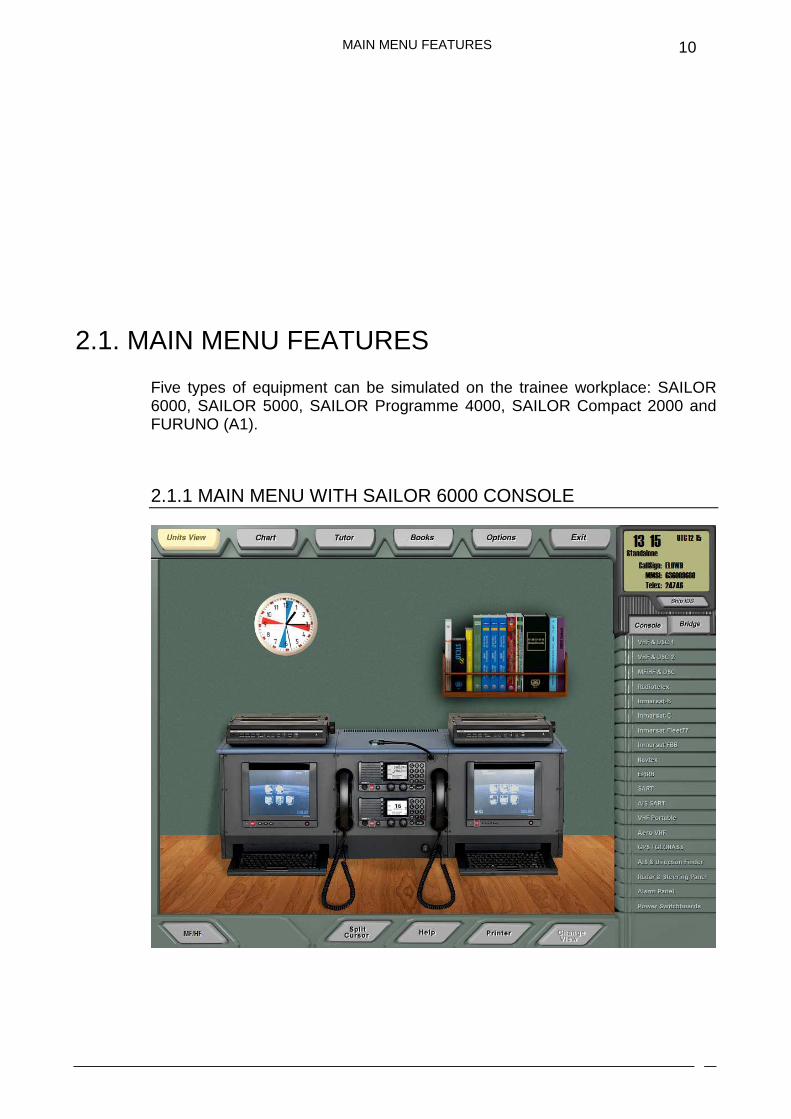
2.1.1 MAIN MENU WITH SAILOR 6000 CONSOLE

MAIN MENU FEATURES
11
The Sailor 6000 Main Menu contains a picture of a GMDSS radio console manufactured by the Danish company Thrane&Thrane (SAILOR 6000), including the following units:
� VHF radio station with DSC 6222.
� Control panel of MF/HF radio station with DSC 6301 and telex terminal.
� INMARSAT-C ship earth station 6110 with EGC receiver.
The menu also contains a picture of a bookshelf with a selection of IMO and ITU-R publications, and a GMDSS Guide arranged on it. By using the mouse, the user can select the bookshelf to be shown on the screen, choose a required book and open the book to read and familiarise his or herself with its content.
Located in the right hand part of the Main Menu is a list of buttons used for displaying any of the simulated units on the screen. This list includes the following buttons:
VHF&DSC 1 Main VHF radio station with DSC
VHF&DSC 2 Additional VHF radio station with DSC
MF/HF&DSC MF/HF radio station with DSC modem and scanning receiver
Radiotelex MF/HF Radiotelex terminal
Inmarsat-B INMARSAT-B ship earth station
Inmarsat-C INMARSAT-C ship earth station
Inmarsat Fleet77 INMARSAT Fleet77 ship earth station
Inmarsat FBB
Navtex
INMARSAT FleetBroadband ship earth station
NAVTEX receiver
EPIRB COSPAS/SARSAT EPIRB
SART Search and rescue transponder
AIS-SART Survival craft AIS search and rescue transmitter
VHF Portable Portable GMDSS VHF radio
Aero VHF Airborne VHF radio station
GPS/Glonass GPS receiver + Glonass/GPS receiver
AIS & Direction Finder AIS Class A + Radio Direction Finder for Search and Rescue
Radar & Steering Panel Ship borne radar + Steering Panel
Alarm Panel GMDSS Distress Alarm Panel
Power Switchboards Main power feeder switchboard + Reserve power feeder switchboard
MAIN MENU FEATURES
12
2.1.2 MAIN MENU WITH SAILOR 5000 CONSOLE
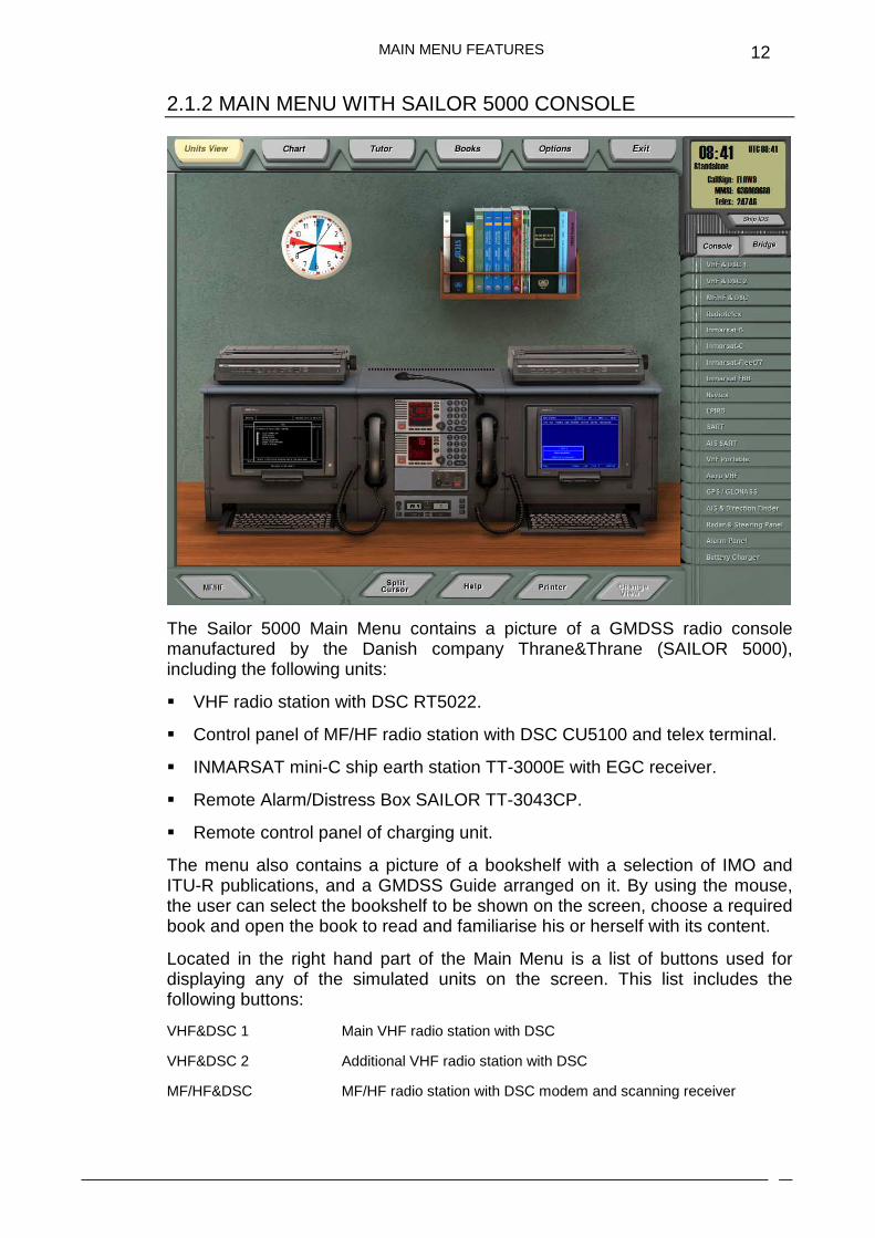
The Sailor 5000 Main Menu contains a picture of a GMDSS radio console manufactured by the Danish company Thrane&Thrane (SAILOR 5000), including the following units:
� VHF radio station with DSC RT5022.
� Control panel of MF/HF radio station with DSC CU5100 and telex terminal.
� INMARSAT mini-C ship earth station TT-3000E with EGC receiver.
� Remote Alarm/Distress Box SAILOR TT-3043CP.
� Remote control panel of charging unit.
The menu also contains a picture of a bookshelf with a selection of IMO and ITU-R publications, and a GMDSS Guide arranged on it. By using the mouse, the user can select the bookshelf to be shown on the screen, choose a required book and open the book to read and familiarise his or herself with its content.
Located in the right hand part of the Main Menu is a list of buttons used for displaying any of the simulated units on the screen. This list includes the following buttons:
VHF&DSC 1 Main VHF radio station with DSC
VHF&DSC 2 Additional VHF radio station with DSC
MF/HF&DSC MF/HF radio station with DSC modem and scanning receiver
MAIN MENU FEATURES
13
Radiotelex MF/HF Radiotelex terminal
Inmarsat-B INMARSAT-B ship earth station
Inmarsat-C INMARSAT mini-C ship earth station
Inmarsat Fleet77 INMARSAT Fleet77 ship earth station
Inmarsat FBB
Navtex
INMARSAT FleetBroadband ship earth station
NAVTEX receiver
EPIRB COSPAS/SARSAT EPIRB
SART Search and rescue transponder
AIS-SART Survival craft AIS search and rescue transmitter
VHF Portable Portable GMDSS VHF radio
Aero VHF Airborne VHF radio station
GPS/Glonass GPS receiver / Glonass-GPS receiver
AIS & Direction Finder AIS Class A transceiver + Radio Direction Finder for Search and Rescue
Radar & Steering Panel Ship borne radar + Steering Panel
Alarm Panel GMDSS Distress Alarm Panel
Battery Charger Charging unit control panel + Main power feeder switchboard + Reserve power feeder switchboard
MAIN MENU FEATURES
14
2.1.3 MAIN MENU WITH SAILOR PROGRAMME 4000 CONSOLE
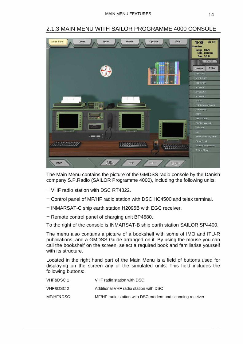
The Main Menu contains the picture of the GMDSS radio console by the Danish company S.P.Radio (SAILOR Programme 4000), including the following units:
− VHF radio station with DSC RT4822.
− Control panel of MF/HF radio station with DSC HC4500 and telex terminal.
− INMARSAT-C ship earth station Н2095В with EGC receiver.
− Remote control panel of charging unit BP4680.
To the right of the console is INMARSAT-B ship earth station SAILOR SP4400.
The menu also contains a picture of a bookshelf with some of IMO and ITU-R publications, and a GMDSS Guide arranged on it. By using the mouse you can call the bookshelf on the screen, select a required book and familiarise yourself with its structure.
Located in the right hand part of the Main Menu is a field of buttons used for displaying on the screen any of the simulated units. This field includes the following buttons:
VHF&DSC 1 VHF radio station with DSC
VHF&DSC 2 Additional VHF radio station with DSC
MF/HF&DSC MF/HF radio station with DSC modem and scanning receiver
MAIN MENU FEATURES
15
Radiotelex MF/HF Radiotelex terminal
Inmarsat-A INMARSAT-A ship earth station
Inmarsat-B INMARSAT-B ship earth station
Inmarsat-C INMARSAT-C ship earth station
Inmarsat Fleet77 INMARSAT Fleet77 ship earth station
Navtex NAVTEX receiver
EPIRB COSPAS/SARSAT EPIRB
SART Search and rescue transponder
VHF Portable Portable GMDSS VHF radio
Aero VHF Airborne VHF radio station
GPS GPS receiver
Direction Finder Radio Direction Finder for Search and Rescue
Radar & Steering Panel Shipborne radar and Steering panel
Alarm Panel GMDSS Distress Alarm Panel
Battery Charger Charging unit control panel + Feeder switchboards for main and reserve power source
When a button is pressed, the corresponding unit is displayed on the screen instead of the radio console presentation.
MAIN MENU FEATURES
16
2.1.4 MAIN MENU WITH SAILOR COMPACT 2000 CONSOLE
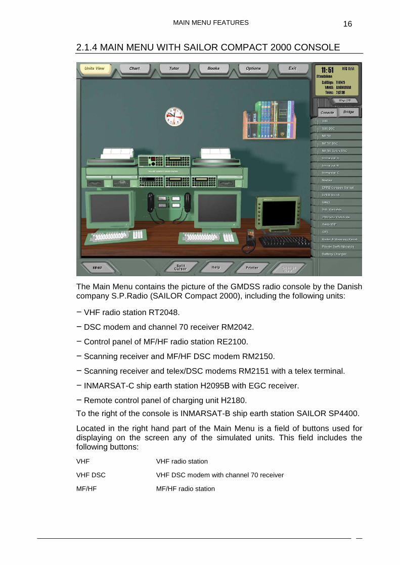
The Main Menu contains the picture of the GMDSS radio console by the Danish company S.P.Radio (SAILOR Compact 2000), including the following units:
− VHF radio station RT2048.
− DSC modem and channel 70 receiver RM2042.
− Control panel of MF/HF radio station RE2100.
− Scanning receiver and MF/HF DSC modem RM2150.
− Scanning receiver and telex/DSC modems RM2151 with a telex terminal.
− INMARSAT-C ship earth station Н2095В with EGC receiver.
− Remote control panel of charging unit Н2180.
To the right of the console is INMARSAT-B ship earth station SAILOR SP4400.
Located in the right hand part of the Main Menu is a field of buttons used for displaying on the screen any of the simulated units. This field includes the following buttons:
VHF VHF radio station
VHF DSC VHF DSC modem with channel 70 receiver
MF/HF MF/HF radio station
MAIN MENU FEATURES
17
MF/HF DSC MF/HF DSC modem with a scanning receiver
MF/HF Telex/DSC MF/HF modems, telex and DSC with a scanning receiver
Radiotelex Radiotelex terminal
Inmarsat-B INMARSAT-B ship earth station
Inmarsat-C INMARSAT-C ship earth station
Inmarsat Fleet77 INMARSAT Fleet77 ship earth station
Navtex NAVTEX receiver
EPIRB COSPAS/SARSAT EPIRB
SART Search and rescue transponder
VHF Portable Portable GMDSS VHF radio
Aero VHF Airborne VHF radio station
GPS GPS receiver
Direction Finder Radio Direction Finder for Search and Rescue
Radar & Steering panel Shipborne radar and Steering panel
Battery Charger Charging unit control panel + Feeder switchboards for main and reserve power source
When a button is pressed, the corresponding unit is displayed on the screen instead of the radio console presentation.
MAIN MENU FEATURES
18
2.1.5 MAIN MENU WITH FURUNO (A1)
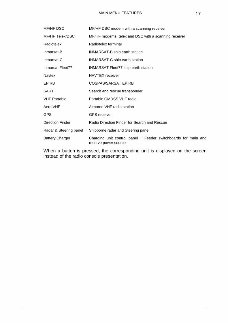
The Furuno (A1) Main Menu contains a picture of a VHF DSC station FM-8800S manufactured by the Japanese company Furuno.
Located to the right hand side of the Main Menu is a list of buttons used for displaying any of the simulated units on the screen. This list includes the following buttons:
VHF&DSC 1 Main VHF radio station with DSC
VHF&DSC 2 Additional VHF radio station with DSC
Navtex NAVTEX receiver
EPIRB COSPAS/SARSAT EPIRB
SART Search and rescue transponder
VHF Portable Portable GMDSS VHF radio
Aero VHF Airborne VHF radio station
GPS GPS receiver
Radar & Steering Panel Ship borne radar + Steering Panel
Battery Charger Charging unit control panel + Main power feeder switchboard + Reserve power feeder switchboard
MAIN MENU FEATURES
19
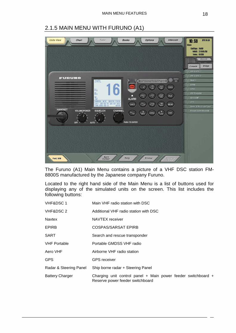
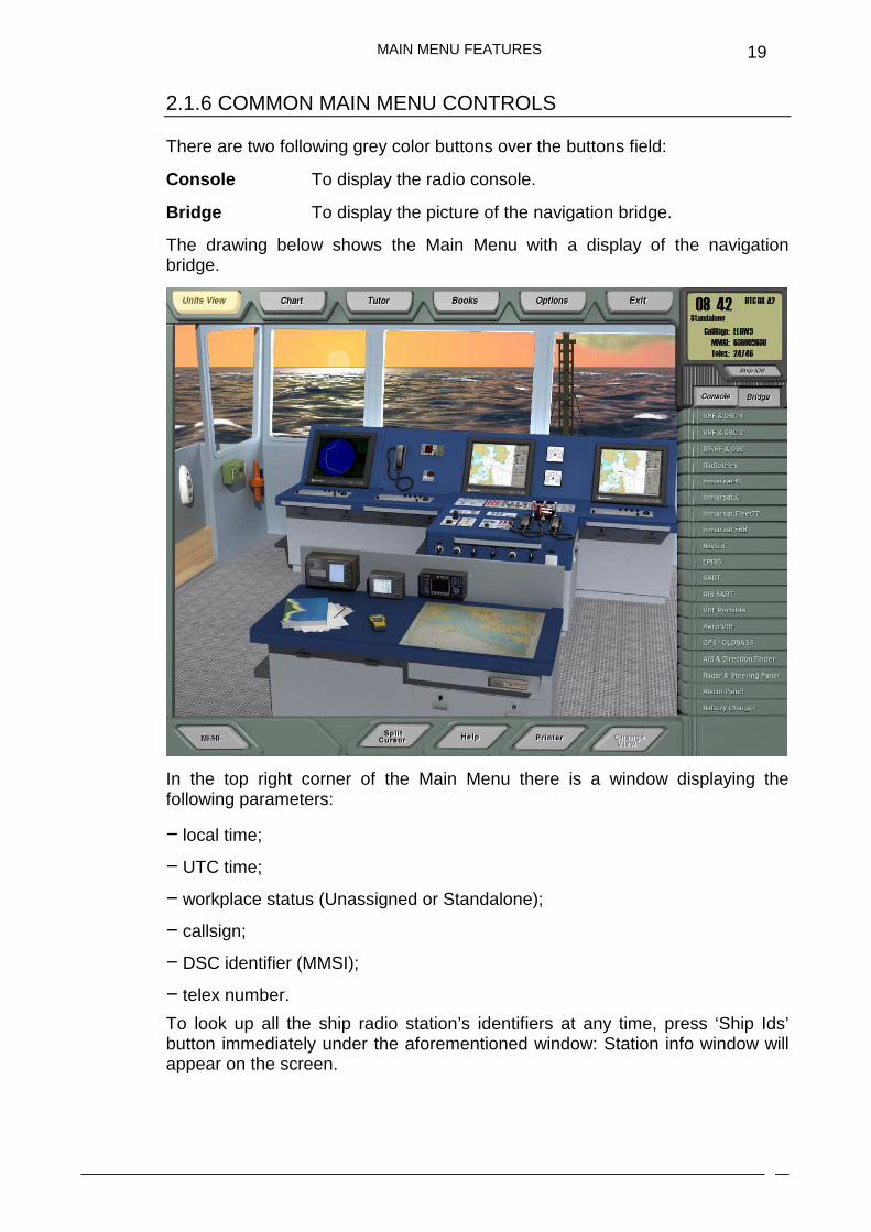
2.1.6 COMMON MAIN MENU CONTROLS
There are two following grey color buttons over the buttons field:
Console To display the radio console.
Bridge To display the picture of the navigation bridge.
The drawing below shows the Main Menu with a display of the navigation bridge.
In the top right corner of the Main Menu there is a window displaying the following parameters:
− local time;
− UTC time;
− workplace status (Unassigned or Standalone);
− callsign;
− DSC identifier (MMSI);
− telex number.
To look up all the ship radio station’s identifiers at any time, press ‘Ship Ids’ button immediately under the aforementioned window: Station info window will appear on the screen.

MAIN MENU FEATURES
20
You can display any of the units on the screen not only by pressing relevant buttons, but also by positioning the marker on the required unit on the presentation of the radio console or the navigation bridge, and pressing the left mouse button.
From the main menu, the trainee can at any time:
� switch to instrument control mode, or to electronic chart display mode, or the Self-Education mode.
� call the information reference system and auxiliary setup window; a HELP system on that unit will be displayed on the screen.
� switch to the printer window of the specific unit.
� display another unit related to the currently displayed communication device.
� imitate connection of the microtelephone handset.
FUNCTIONAL DESCRIPTION
21
2.2. FUNCTIONAL DESCRIPTION
2.2.1 USE OF EXTERNAL LOUDSPEAKERS AND SIMULATION OF MICROTELEPHONE HANDSET
The simulator provides for the connection of a simulated microtelephone handset attached to the required communication device.
In the left bottom part of the screen there is a button labelled by default as MF/HF. The label on the button changes to indicate which communication device the simulated microtelephone handset is currently connected to. If the button is labelled MF/HF, this means that the handset is connected to MF/HF radio station. Place the cursor on the button and right-click on the “mouse”. The MF/HF button is then highlighted in yellow. This means that the handset is lifted from the holder and the push-to-talk switch is activated. You can start transmission in MF/HF band using whichever MF/HF station frequency the radio is tuned to. After you press MF/HF button a second time, the button returns to the non-activated grey colour. This indicates that the handset has been returned to the holder.
When another station allowing radiotelephone communication to be maintained is called on the screen, e.g., INMARSAT-B, the handset will automatically be switched to this station.
Additionally the user can switch the handset manually to any other communication device which is not currently displayed on the screen.
Active loudspeakers connected to the sound card are used for listening to the required frequencies (channels).

FUNCTIONAL DESCRIPTION
22
2.2.2 PRINTING OUT
The simulator enables information received and transmitted by all the units which have an output onto the printer, to be printed out for records and review by the trainee.
The external printer should be connected to LPT1 port.
A useful aspect of this system is, if you do not have a facility for an external printer, this function is optional, as the simulator program imitates a printer which can be displayed on the screen.
2.2.3 ALARMS
Some units included in the simulator generate an audible alarm upon the receipt of important messages or when the vessel is made to switch to a certain status, in order to draw the operator’s attention to the change or problem.
The simulator program automatically switches on a visual alarm to warn the operator of any such circumstance.

FUNCTIONAL DESCRIPTION
23
2.2.4 CHART SYSTEM
GENERAL INFORMATION
During work with the simulator, the trainee can use the electronic chart system included in the system funcitons. This option provides the following capabilities:
� to view any chart fragment on a suitable scale;
� to determine coordinates of any object plotted on the chart;
� to determine the distance and bearing between any two points on the chart;
� obtain and change ownship coordinates, course and speed;
� to plot other trainees’ ships on the chart, setting their coordinates, names, types and icon colours;
� to obtain information on any of the previously plotted ships;
� to use the database of coast radio stations, NAVTEX system stations and INMARSAT coast earth stations.
� to view GMDSS Sea Areas and Search and Rescue Regions.
� availability to make a rough estimate of the radio waves propagation in the selected frequency band.
CHART FEATURES
FUNCTIONAL DESCRIPTION
24
The electronic chart system allows the following objects to be displayed on the chart:
� outlines of the electronic nautical charts;
� ships;
� coast VHF/MF/HF radio stations;
� NAVTEX stations;
� INMARSAT coast earth stations;
� GMDSS Sea Areas and SRRs.
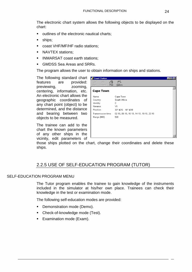
The program allows the user to obtain information on ships and stations.
The following standard chart features are provided: previewing, zooming, centering, information, etc. An electronic chart allows the geographic coordinates of any chart point (object) to be determined, and the distance and bearing between two objects to be measured.
The trainee can add to the chart the known parameters of any other ships in the vicinity, edit parameters of those ships plotted on the chart, change their coordinates and delete these ships.
2.2.5 USE OF SELF-EDUCATION PROGRAM (TUTOR)
SELF-EDUCATION PROGRAM MENU
The Tutor program enables the trainee to gain knowledge of the instruments included in the simulator at his/her own place. Trainees can check their knowledge in the test or examination mode.
The following self-education modes are provided:
� Demonstration mode (Demo).
� Check-of-knowledge mode (Test).
� Examination mode (Exam).
FUNCTIONAL DESCRIPTION
25
It is advisable to use the demonstration mode for the process of training in the handling of instruments. This program will show, when operated in automatic mode, the procedure for completion of the selected exercise. The program’s operation is complemented with clarifications and comments displayed on the screen. There are two demo modes whilst using the self-education program:
� AUTO: The program automatically completes the entire exercise passing to each following step after a pre-defined time interval.
� STEP BY STEP: The program automatically completes the exercise, however, in order to go on to the next exercise step, the user must click the left mouse button or any key on the keyboard. The Step by Step mode has been specifically designed to aid individual training, as it allows the user to learn at their optimum work rate. Each trainee is therefore given the opportunity to read comments on each step in their own time and ensure that each step serves as a useful learning example.
It is advisable to use the check-of-knowledge function after working in demonstration mode, as this enables the trainee to accurately review progress made and highlight any areas that may need further exercise practise.
The final stage in the self-education mode is an examination in the trainee’s operation of instruments included in the simulator.
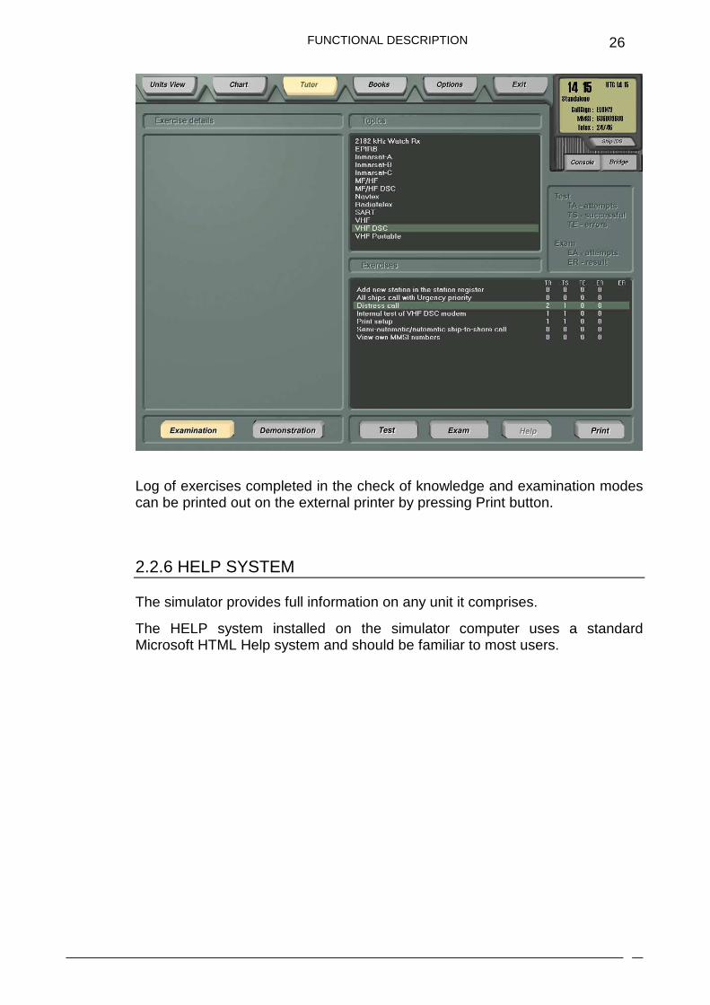
The program keeps a log of exercises completed in both the checks of knowledge and examination modes. After pressing the Examination button, an Exercises window displays statistics for each of the exercises. These statistics include the following information distributed among the columns:
� number of attempts to complete the given exercise in test mode
� number of successful attempts in test mode
� number of errors in the last attempt in test mode
� number of attempts to complete the given exercise in examination mode
� examination result.
FUNCTIONAL DESCRIPTION
26
Log of exercises completed in the check of knowledge and examination modes can be printed out on the external printer by pressing Print button.
2.2.6 HELP SYSTEM
The simulator provides full information on any unit it comprises.
The HELP system installed on the simulator computer uses a standard Microsoft HTML Help system and should be familiar to most users.

SIMULATED EQUIPMENT
27
2.3. SIMULATED EQUIPMENT
2.3.1 VHF RADIO STATION WITH DSC SAILOR 6222
The program provides imitation of the following principal functions:
� turning ON/OFF and volume control;
� adjusting the squelch level;
� selection of any out of 55 international channels;
� prompt selection of call and distress channel 16;
� function of keeping watch on two or three channels;
� programming and operation in the channel scanning mode;
� reduction of the station’s transmitting power;
� setting of channels used in the USA;
� changing the display light, night view;
� manual and automatic input of position and time;
� viewing of the own MMSI number;
SIMULATED EQUIPMENT
28
� transmission of a distress call using the “hot” key;
� preparation, transmission, and reception of all the types of DSC calls required for the class A VHF DSC equipment;
� DSC and voice communication sessions; active and on hold sessions;
� keeping watch on channel 70;
� acoustic alarm upon the reception of distress calls as well as calls requiring the operator’s presence;
� storage and viewing of 20 last received DSC distress calls, calls unrelated to the distress and transmitted calls;
� DSC Self Test;
� address book and a facility for editing it;
� printing out of the DSC messages;
� replay of the latest 240 seconds of received voice data;
� setting up some options in accordance with the unit description.
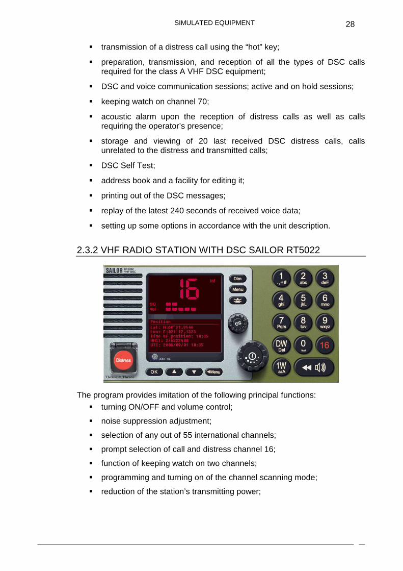
2.3.2 VHF RADIO STATION WITH DSC SAILOR RT5022
The program provides imitation of the following principal functions:
� turning ON/OFF and volume control;
� noise suppression adjustment;
� selection of any out of 55 international channels;
� prompt selection of call and distress channel 16;
� function of keeping watch on two channels;
� programming and turning on of the channel scanning mode;
� reduction of the station’s transmitting power;
SIMULATED EQUIPMENT
29
� setting of channels used in the USA;
� changing of the display illumination;
� manual and automatic input of coordinates and time;
� viewing of the own MMSI numbers;
� transmission of a distress call using the “hot” key;
� preparation, transmission and reception of all the types of DSC calls required for the class A VHF DSC equipment;
� keeping watch on channel 70;
� acoustic alarm upon the reception of distress calls, as well as calls requiring the operator’s presence;
� control of the channels and transmitting power of the VHF radio station;
� storage and viewing of 20 last received DSC distress calls and calls unrelated to the distress;
� check of the modem without transmission;
� address book and a facility for editing it;
� printing out of the received messages;
� replay of the latest 90 seconds of received voice data;
� setting of options in accordance with the description of the unit.
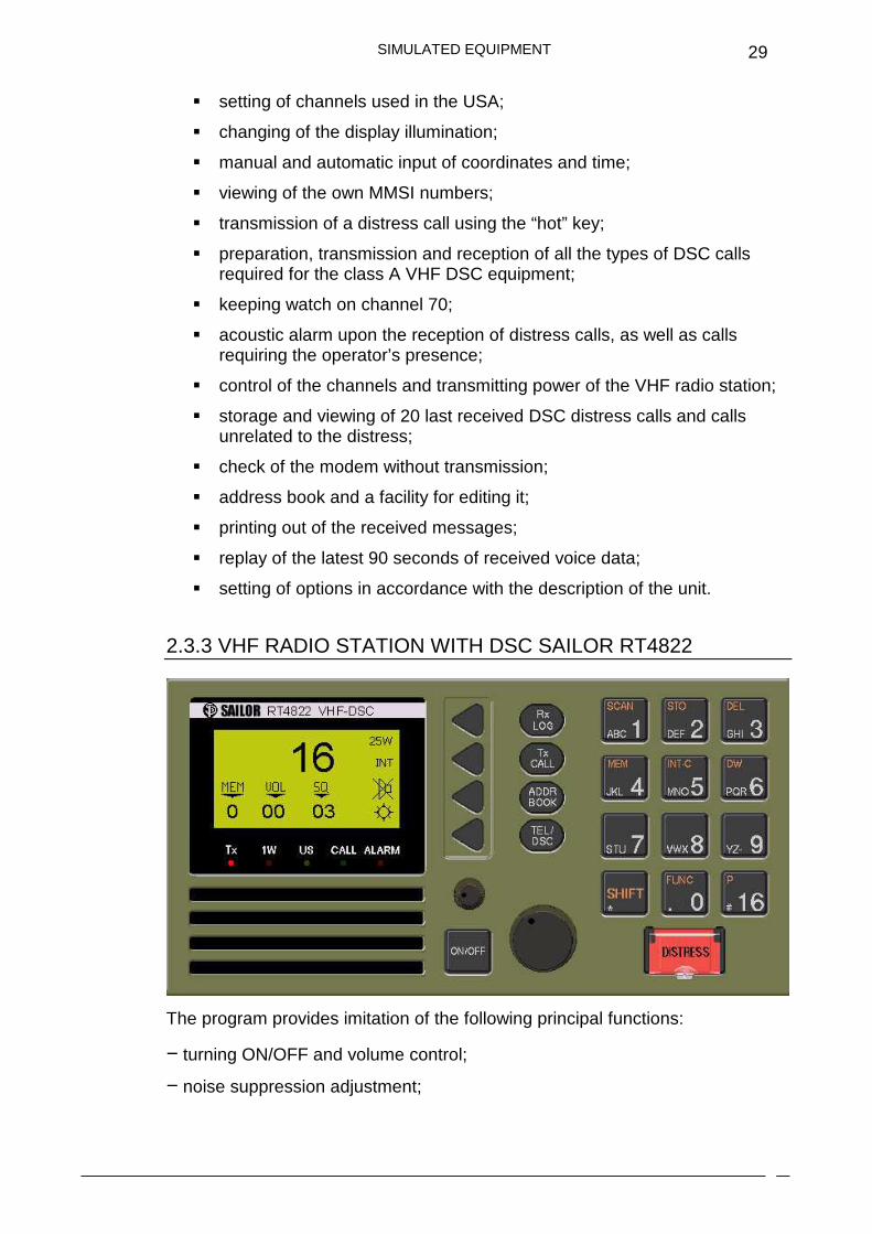
2.3.3 VHF RADIO STATION WITH DSC SAILOR RT4822
The program provides imitation of the following principal functions:
− turning ON/OFF and volume control;
− noise suppression adjustment;

SIMULATED EQUIPMENT
30
− selection of any out of 55 international channels;
− prompt selection of call and distress channel 16;
− function of keeping watch on two channels;
− programming and turning on of the channel scanning mode;
− reduction of the station’s transmitting power;
− setting of channels used in the USA;
− changing of the display illumination;
− manual and automatic input of coordinates and time;
− viewing of the own MMSI numbers;
− transmission of a distress call using the «hot» key;
− preparation, transmission and reception of all the types of DSC calls required for the class A VHF DSC equipment;
− keeping watch on channel 70;
− acoustic alarm upon the reception of distress calls, as well as calls requiring the operator’s presence;
− list of stations and a facility for editing it;
− control of the channels and transmitting power of the VHF radio station;
− storage and viewing of 20 last received DSC distress calls and calls unrelated to the distress;
− check of the modem without transmission;
− address book and a facility for editing it;
− printing out of the received messages;
− setting of options in accordance with the description of the unit.
By pressing HELP button the trainee can familiarise him/herself in detail with the procedure to operate a VHF radio station. HELP system allows obtaining full information on the control of all the instruments imitated in the simulator.
SIMULATED EQUIPMENT
31
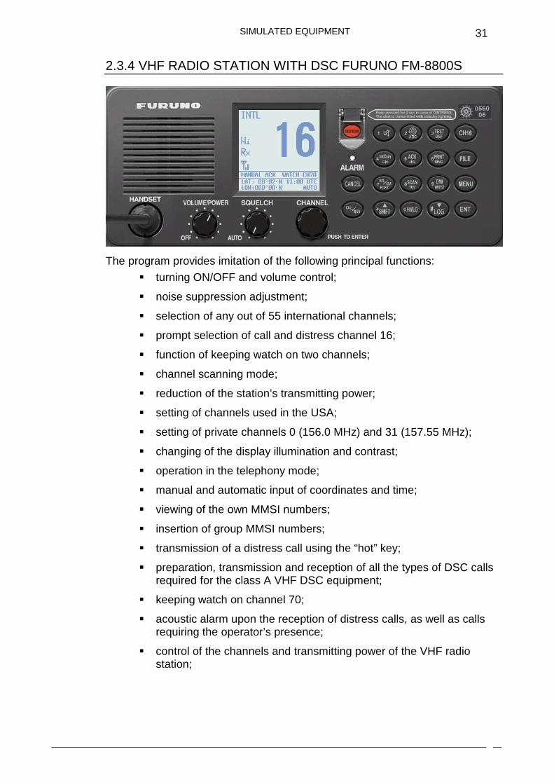
2.3.4 VHF RADIO STATION WITH DSC FURUNO FM-8800S
The program provides imitation of the following principal functions:
� turning ON/OFF and volume control;
� noise suppression adjustment;
� selection of any out of 55 international channels;
� prompt selection of call and distress channel 16;
� function of keeping watch on two channels;
� channel scanning mode;
� reduction of the station’s transmitting power;
� setting of channels used in the USA;
� setting of private channels 0 (156.0 MHz) and 31 (157.55 MHz);
� changing of the display illumination and contrast;
� operation in the telephony mode;
� manual and automatic input of coordinates and time;
� viewing of the own MMSI numbers;
� insertion of group MMSI numbers;
� transmission of a distress call using the “hot” key;
� preparation, transmission and reception of all the types of DSC calls required for the class A VHF DSC equipment;
� keeping watch on channel 70;
� acoustic alarm upon the reception of distress calls, as well as calls requiring the operator’s presence;
� control of the channels and transmitting power of the VHF radio station;
SIMULATED EQUIPMENT
32
� storage and viewing of 50 last received DSC distress calls and calls unrelated to the distress;
� check of the modem without transmission;
� address book and a facility for editing it;
� printing out of the received messages;
� setting of options in accordance with the description of the unit.
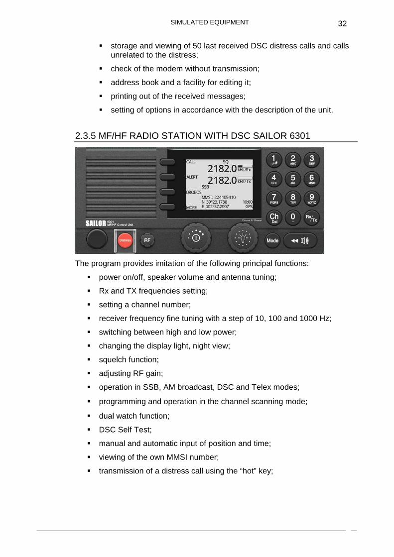
2.3.5 MF/HF RADIO STATION WITH DSC SAILOR 6301
The program provides imitation of the following principal functions:
� power on/off, speaker volume and antenna tuning;
� Rx and TX frequencies setting;
� setting a channel number;
� receiver frequency fine tuning with a step of 10, 100 and 1000 Hz;
� switching between high and low power;
� changing the display light, night view;
� squelch function;
� adjusting RF gain;
� operation in SSB, AM broadcast, DSC and Telex modes;
� programming and operation in the channel scanning mode;
� dual watch function;
� DSC Self Test;
� manual and automatic input of position and time;
� viewing of the own MMSI number;
� transmission of a distress call using the “hot” key;

SIMULATED EQUIPMENT
33
� preparation, transmission and reception of all the types of DSC calls
required for the class A MF/HF DSC equipment;
� acoustic alarm upon the reception of distress calls, as well as calls
requiring the operator’s presence;
� DSC and voice communication sessions; active and on hold sessions;
� list of contacts and a facility for editing it;
� keeping watch on the distress DSC frequencies;
� keeping watch on the public DSC frequency;
� printing out of the DSC messages;
� replay of the latest 240 seconds of received voice data;
� storage and viewing of up to 20 last received distress calls, calls
unrelated to the distress and transmitted calls;
� setting of some options in accordance with the description of the unit.
2.3.6 MF/HF RADIO STATION WITH DSC SAILOR CU5100
The program provides imitation of the following principal functions:
� turning ON/OFF and volume control;
� setting of the reception and transmission frequencies;
� setting the channel number;
� receiver frequency control with a step of 10, 100 and 1000 Hz;
� selection of the transmission mode;
� changing of the transmitter’s output power;
SIMULATED EQUIPMENT
34
� changing of the display illumination;
� switching on/off of the noise suppression;
� operation in the telephony mode, as well as in combination with the DSC
and telex modem;
� manual and automatic input of coordinates and time;
� viewing of the own MMSI numbers;
� internal and external check;
� transmission of a distress call using the «hot» key;
� preparation, transmission and reception of all the types of DSC calls
required for the class A MF/HF DSC equipment;
� acoustic alarm upon the reception of distress calls, as well as calls
requiring the operator’s presence;
� list of stations and a facility for editing it;
� keeping watch on the distress DSC frequencies;
� keeping watch on the public DSC frequencies;
� storage and viewing of up to 20 last received distress calls and calls
unrelated to the distress;
� setting of options in accordance with the description of the unit.
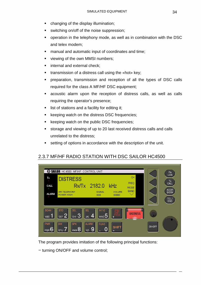
2.3.7 MF/HF RADIO STATION WITH DSC SAILOR HC4500
The program provides imitation of the following principal functions:
− turning ON/OFF and volume control;
SIMULATED EQUIPMENT
35
− manual and automatic gain adjustment;
− setting of the reception and transmission frequencies;
− setting the channel number;
− receiver frequency control with a step of 10, 100, 500 and 1000 Hz;
− selection of the transmission mode;
− changing of the transmitter’s output power;
− tuning of the station to 2182 kHz frequency by using a single key;
− transmission of a radio telephone alarm signal;
− acoustic check of the radio telephone alarm generator;
− changing of the display illumination;
− switching on/off of the noise suppression;
− operation in combination with the DSC and telex modem;
− manual and automatic input of coordinates and time;
− viewing of the own MMSI numbers;
− internal and external check;
− transmission of a distress call using the «hot» key;
− preparation, transmission and reception of all the types of DSC calls required for the class A MF/HF DSC equipment;
− acoustic alarm upon the reception of distress calls, as well as calls requiring the operator’s presence;
− list of stations and a facility for editing it;
− keeping watch on the distress DSC frequencies;
− keeping watch on the public DSC frequencies;
− storage and viewing of up to 20 last received distress calls and calls unrelated to the distress;
− setting of options in accordance with the description of the unit.

SIMULATED EQUIPMENT
36
2.3.8 MF/HF RADIOTELEX TERMINAL SAILOR 6300
The program provides imitation of the following principal functions:
� text editor for the preparation of telex messages;
� printing, saving and deleting messages;
� using a virtual keyboard;
� operation in ARQ and FEC modes;
� calling of and work with a coast radio station in ARQ mode in accordance with procedures of ITU-R Recommendation M.492 (manual operation mode only);
� keeping watch on the selected scan frequencies;
� editing the scan list;
� contacts list with a facility for editing it;
� power status;
� setting of some options in accordance with the description of the unit.
SIMULATED EQUIPMENT
37
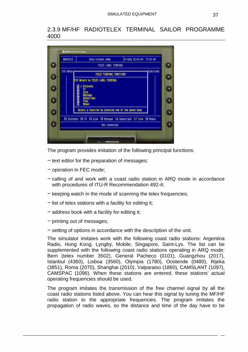
2.3.9 MF/HF RADIOTELEX TERMINAL SAILOR PROGRAMME 4000
The program provides imitation of the following principal functions:
− text editor for the preparation of messages;
− operation in FEC mode;
− calling of and work with a coast radio station in ARQ mode in accordance with procedures of ITU-R Recommendation 492-4;
− keeping watch in the mode of scanning the telex frequencies;
− list of telex stations with a facility for editing it;
− address book with a facility for editing it;
− printing out of messages;
− setting of options in accordance with the description of the unit.
The simulator imitates work with the following coast radio stations: Argentina Radio, Hong Kong, Lyngby, Mobile, Singapore, Saint-Lys. The list can be supplemented with the following coast radio stations operating in ARQ mode: Bern (telex number 3502), General Pacheco (0101), Guangzhou (2017), Istanbul (4360), Lisboa (3560), Olympia (1780), Oostende (0480), Rijeka (3851), Roma (2070), Shanghai (2010), Valparaiso (1860), CAMSLANT (1097), CAMSPAC (1096). When these stations are entered, these stations’ actual operating frequencies should be used.
The program imitates the transmission of the free channel signal by all the coast radio stations listed above. You can hear this signal by tuning the MF/HF radio station to the appropriate frequencies. The program imitates the propagation of radio waves, so the distance and time of the day have to be
SIMULATED EQUIPMENT
38
taken into account in the selection of communication frequencies for a parti-cular radio station.
2.3.10 MF/HF RADIOTELEX TERMINAL SAILOR 5000
The program provides imitation of the following principal functions: � text editor for the preparation of telex messages;
� operation in FEC mode;
� calling of and work with a coast radio station in ARQ mode in
accordance with procedures of ITU-R Recommendation M.492 (manual
operation mode only);
� rephasing procedure in accordance with ITU-R Recommendation M.625;
� keeping watch on a selected telex frequency;
� list of telex stations with a facility for editing it;
� address book with a facility for editing it;
� printing out of telex messages;
� setting of options in accordance with the description of the unit.
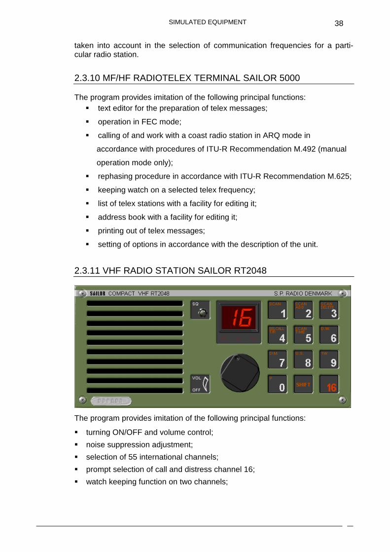
2.3.11 VHF RADIO STATION SAILOR RT2048
The program provides imitation of the following principal functions:
� turning ON/OFF and volume control;
� noise suppression adjustment;
� selection of 55 international channels;
� prompt selection of call and distress channel 16;
� watch keeping function on two channels;

SIMULATED EQUIPMENT
39
� programming and turning on, of the channel scanning mode;
� reduction of the station’s transmitting power;
� setting of channels used in the USA;
� changing of the display illumination;
� work with DSC modem.
2.3.12 DSC MODEM WITH CHANNEL 70 RECEIVER SAILOR RM2042
The program provides imitation of the following principal functions:
� turning ON/OFF and volume control;
� changing of the display illumination;
� manual and automatic input of coordinates and time;
� viewing of the own MMSI numbers;
� transmission of a distress call using the «hot» keys;
� preparation, transmission and reception of all the types of DSC calls required for class A VHF DSC equipment;
� watch keeping on channel 70;
� acoustic alarm upon the receipt of distress calls, as well as calls requiring the operator’s attention;
� list of stations and a list edit facility;
� control of the channels and transmitting power of the VHF radio station;
� storage and viewing of 20 last received DSC distress calls as well as other unrelated calls;
� check of the modem without transmission;
� address book with edit facility;
� printing received messages;
SIMULATED EQUIPMENT
40
� setting of options in accordance with the description of the unit.
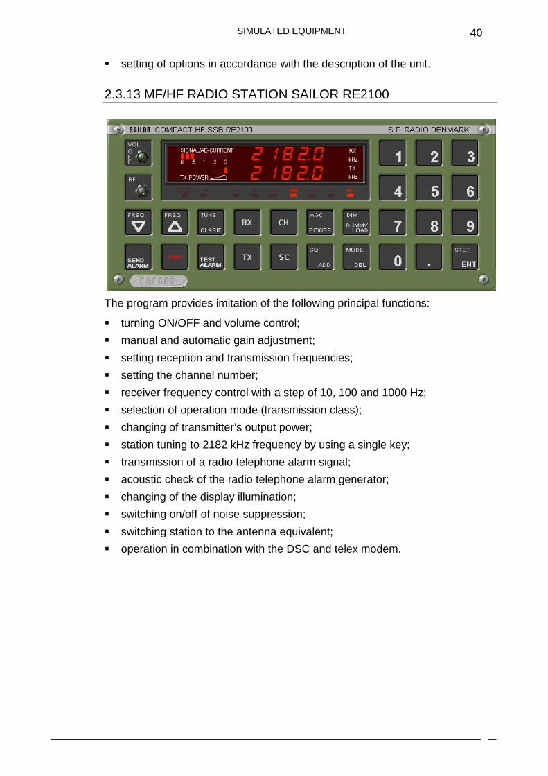
2.3.13 MF/HF RADIO STATION SAILOR RE2100
The program provides imitation of the following principal functions:
� turning ON/OFF and volume control;
� manual and automatic gain adjustment;
� setting reception and transmission frequencies;
� setting the channel number;
� receiver frequency control with a step of 10, 100 and 1000 Hz;
� selection of operation mode (transmission class);
� changing of transmitter’s output power;
� station tuning to 2182 kHz frequency by using a single key;
� transmission of a radio telephone alarm signal;
� acoustic check of the radio telephone alarm generator;
� changing of the display illumination;
� switching on/off of noise suppression;
� switching station to the antenna equivalent;
� operation in combination with the DSC and telex modem.
SIMULATED EQUIPMENT
41
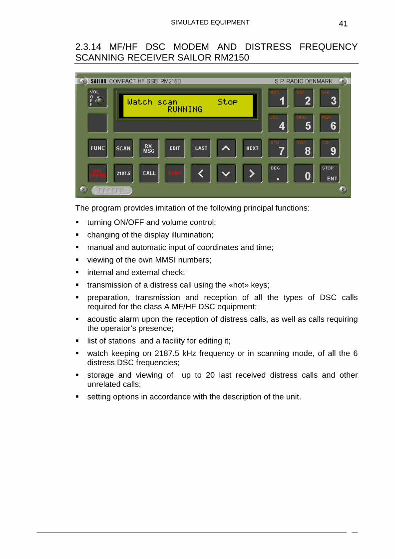
2.3.14 MF/HF DSC MODEM AND DISTRESS FREQUENCY SCANNING RECEIVER SAILOR RM2150
The program provides imitation of the following principal functions:
� turning ON/OFF and volume control;
� changing of the display illumination;
� manual and automatic input of coordinates and time;
� viewing of the own MMSI numbers;
� internal and external check;
� transmission of a distress call using the «hot» keys;
� preparation, transmission and reception of all the types of DSC calls required for the class A MF/HF DSC equipment;
� acoustic alarm upon the reception of distress calls, as well as calls requiring the operator’s presence;
� list of stations and a facility for editing it;
� watch keeping on 2187.5 kHz frequency or in scanning mode, of all the 6 distress DSC frequencies;
� storage and viewing of up to 20 last received distress calls and other unrelated calls;
� setting options in accordance with the description of the unit.
SIMULATED EQUIPMENT
42
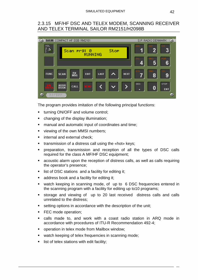
2.3.15 MF/HF DSC AND TELEX MODEM, SCANNING RECEIVER AND TELEX TERMINAL SAILOR RM2151/H2098B
The program provides imitation of the following principal functions:
� turning ON/OFF and volume control;
� changing of the display illumination;
� manual and automatic input of coordinates and time;
� viewing of the own MMSI numbers;
� internal and external check;
� transmission of a distress call using the «hot» keys;
� preparation, transmission and reception of all the types of DSC calls required for the class A MF/HF DSC equipment;
� acoustic alarm upon the reception of distress calls, as well as calls requiring the operator’s presence;
� list of DSC stations and a facility for editing it;
� address book and a facility for editing it;
� watch keeping in scanning mode, of up to 6 DSC frequencies entered in the scanning program with a facility for editing up to10 programs;
� storage and viewing of up to 20 last received distress calls and calls unrelated to the distress;
� setting options in accordance with the description of the unit;
� FEC mode operation;
� calls made to, and work with a coast radio station in ARQ mode in accordance with procedures of ITU-R Recommendation 492-4;
� operation in telex mode from Mailbox window;
� watch keeping of telex frequencies in scanning mode;
� list of telex stations with edit facility;
SIMULATED EQUIPMENT
43
� printing messages.
The program imitates the propagation of radio waves, so the distance and time of the day have to be taken into account in the selection of communication frequencies for a particular radio station. The telex terminal program allows automatic determination of the optimum communication frequencies, ie. those not currently engaged in work with another ship.
The ability to connect with telex and to switch between telex modem and telex terminal monitor is provided.
2.3.16 WATCH RECEIVER 2182 KHZ SAILOR R501
The program provides imitation of the following principal functions:
� turning ON/OFF and volume control;
� turning the loudspeaker OFF;
� setting the internal clock;
� automatic switching ON of the loudspeaker for the time of radio telephone silence periods;
� test check of the receiver.
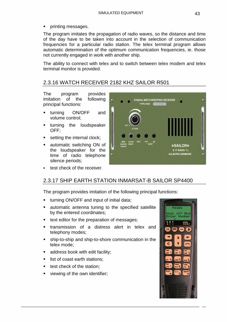
2.3.17 SHIP EARTH STATION INMARSAT-B SAILOR SP4400
The program provides imitation of the following principal functions:
� turning ON/OFF and input of initial data;
� automatic antenna tuning to the specified satellite by the entered coordinates;
� text editor for the preparation of messages;
� transmission of a distress alert in telex and telephony modes;
� ship-to-ship and ship-to-shore communication in the telex mode;
� address book with edit facility;
� list of coast earth stations;
� test check of the station;
� viewing of the own identifier;

SIMULATED EQUIPMENT
44
� viewing and setting of some options in accordance with the description of the unit;
� printing messages.
2.3.18 SHIP EARTH STATION INMARSAT-C SAILOR 6110
The program provides imitation of the following principal functions:
� turning ON/OFF;
� manual and automatic log-in procedures to the satellite;
� manual and automatic input of position;
� transmission of distress alerts by using “hot” key;
� changing the Distress Alert settings and transmission of the distress alert;
� transmission of message with distress priority;
� ship-to-ship and ship-to-shore transmission and reception of messages in the telex mode;
� text editor for the preparation of messages;
� using a virtual keyboard;
� address book with editing facility;
� list of Land Earth Stations;
� link Test mode;
� testing Distress button;

SIMULATED EQUIPMENT
45
� printing of messages;
� programming of the EGC receiver and reception of EGC messages;
� log of transmitted and received messages including EGC messages;
� viewing of own identifier;
� sending of position reports;
� internal GPS receiver;
� power status;
� setting of main options in accordance with the unit description.
2.3.19 SES INMARSAT MINI-C WITH EGC RECEIVER SAILOR TT-3000E AND REMOTE ALARM/DISTRESS BOX TT-3043CP
The program provides imitation of the following principal functions:
� Turning ON/OFF;
� Manual and automatic log-in procedures to the satellite;

SIMULATED EQUIPMENT
46
� Manual and automatic input of coordinates;
� Transmission of distress alerts by using “hot” key at the remote alarm panel TT-3043CP;
� Transmission of message with distress priority;
� Ship-to-ship and ship-to-shore transmission and reception of messages in the telex mode;
� Text editor for the preparation of messages;
� Address book with editing facility;
� List of stations;
� Test mode;
� Printing of messages;
� Programming of the EGC receiver and reception of EGC messages;
� Log of transmitted and received messages including EGC messages;
� Viewing of own identifier;
� Sending of position reports;
� Internal GPS receiver;
� Setting of main options in accordance with the unit description.
2.3.20 SHIP EARTH STATION INMARSAT-C WITH EGC RECEIVER SAILOR H2095C
The program provides imitation of the following principal functions:
� turning ON/OFF and input of initial data;
� manual and automatic procedure of logging to the satellite;
� manual and automatic input of coordinates;
� transmission of distress alerts by using “hot” keys;
� transmission of a message with a distress priority;
� ship-to-ship and ship-to-shore transmission and receipt of messages in telex mode;
� text editor for the preparation of messages;
� address book with edit facility;
SIMULATED EQUIPMENT
47
� list of stations;
� test check of the station;
� printing messages;
� programming of the EGC receiver and reception of EGC messages;
� log of transmitted and received messages and EGC messages;
� viewing of the own identifier;
� sending of position reports;
� setting of the main options in accordance with the unit description.
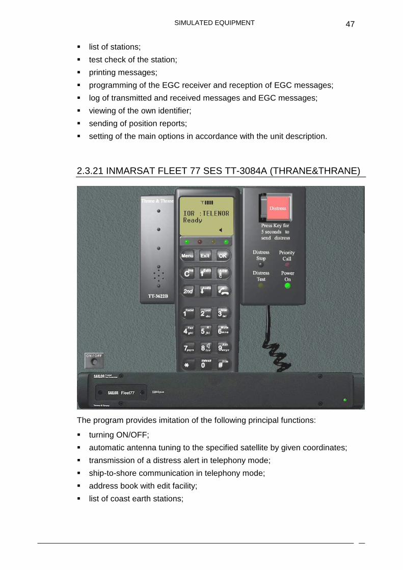
2.3.21 INMARSAT FLEET 77 SES TT-3084A (THRANE&THRANE)
The program provides imitation of the following principal functions:
� turning ON/OFF;
� automatic antenna tuning to the specified satellite by given coordinates;
� transmission of a distress alert in telephony mode;
� ship-to-shore communication in telephony mode;
� address book with edit facility;
� list of coast earth stations;
SIMULATED EQUIPMENT
48
� generic E-mail terminal for MPDS mode of operation;
� viewing and setting of some options in accordance with the unit description.
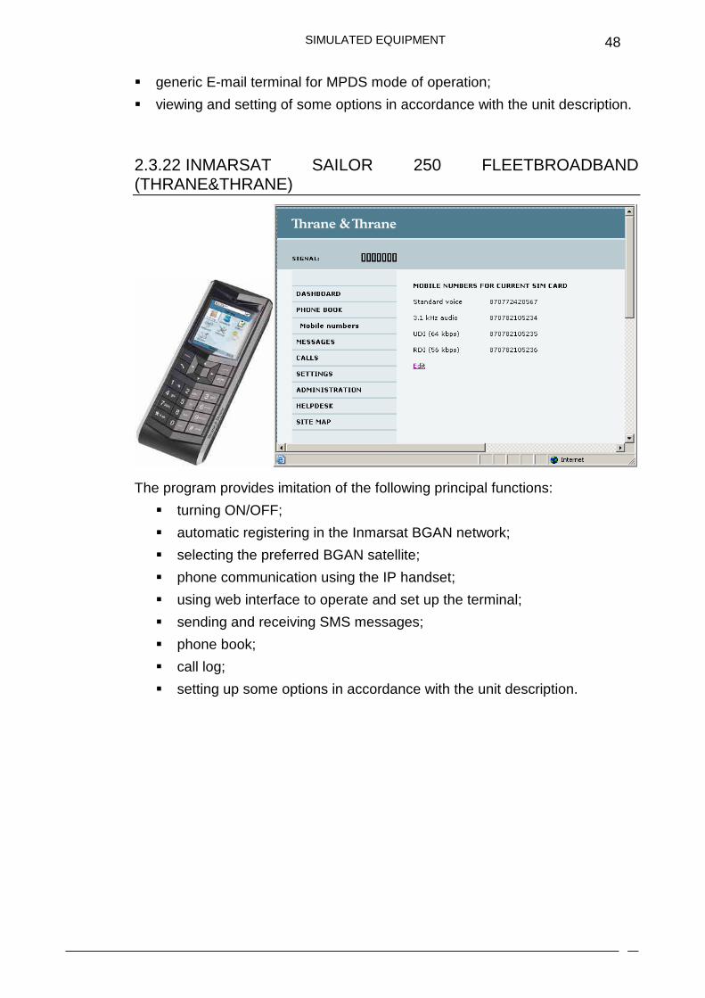
2.3.22 INMARSAT SAILOR 250 FLEETBROADBAND (THRANE&THRANE)
The program provides imitation of the following principal functions:
� turning ON/OFF;
� automatic registering in the Inmarsat BGAN network;
� selecting the preferred BGAN satellite;
� phone communication using the IP handset;
� using web interface to operate and set up the terminal;
� sending and receiving SMS messages;
� phone book;
� call log;
� setting up some options in accordance with the unit description.
SIMULATED EQUIPMENT
49
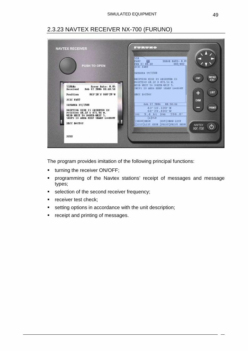
2.3.23 NAVTEX RECEIVER NX-700 (FURUNO)
The program provides imitation of the following principal functions:
� turning the receiver ON/OFF;
� programming of the Navtex stations’ receipt of messages and message types;
� selection of the second receiver frequency;
� receiver test check;
� setting options in accordance with the unit description;
� receipt and printing of messages.
SIMULATED EQUIPMENT
50
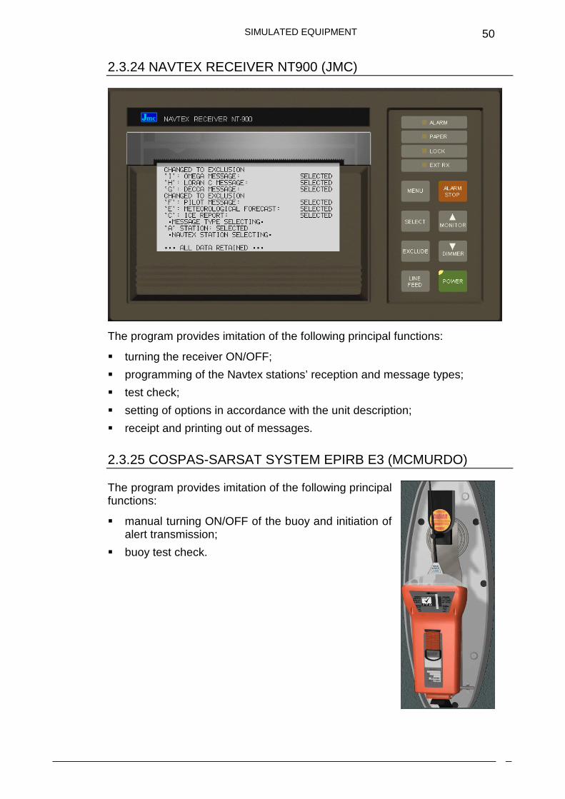
2.3.24 NAVTEX RECEIVER NT900 (JMC)
The program provides imitation of the following principal functions:
� turning the receiver ON/OFF;
� programming of the Navtex stations’ reception and message types;
� test check;
� setting of options in accordance with the unit description;
� receipt and printing out of messages.
2.3.25 COSPAS-SARSAT SYSTEM EPIRB E3 (MCMURDO)
The program provides imitation of the following principal functions:
� manual turning ON/OFF of the buoy and initiation of alert transmission;
� buoy test check.
SIMULATED EQUIPMENT
51
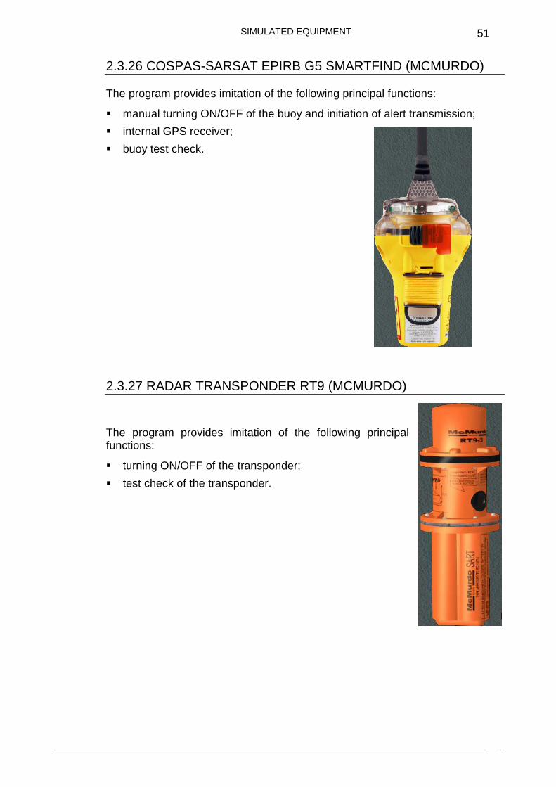
2.3.26 COSPAS-SARSAT EPIRB G5 SMARTFIND (MCMURDO)
The program provides imitation of the following principal functions:
� manual turning ON/OFF of the buoy and initiation of alert transmission;
� internal GPS receiver;
� buoy test check.
2.3.27 RADAR TRANSPONDER RT9 (MCMURDO)
The program provides imitation of the following principal functions:
� turning ON/OFF of the transponder;
� test check of the transponder.
SIMULATED EQUIPMENT
52
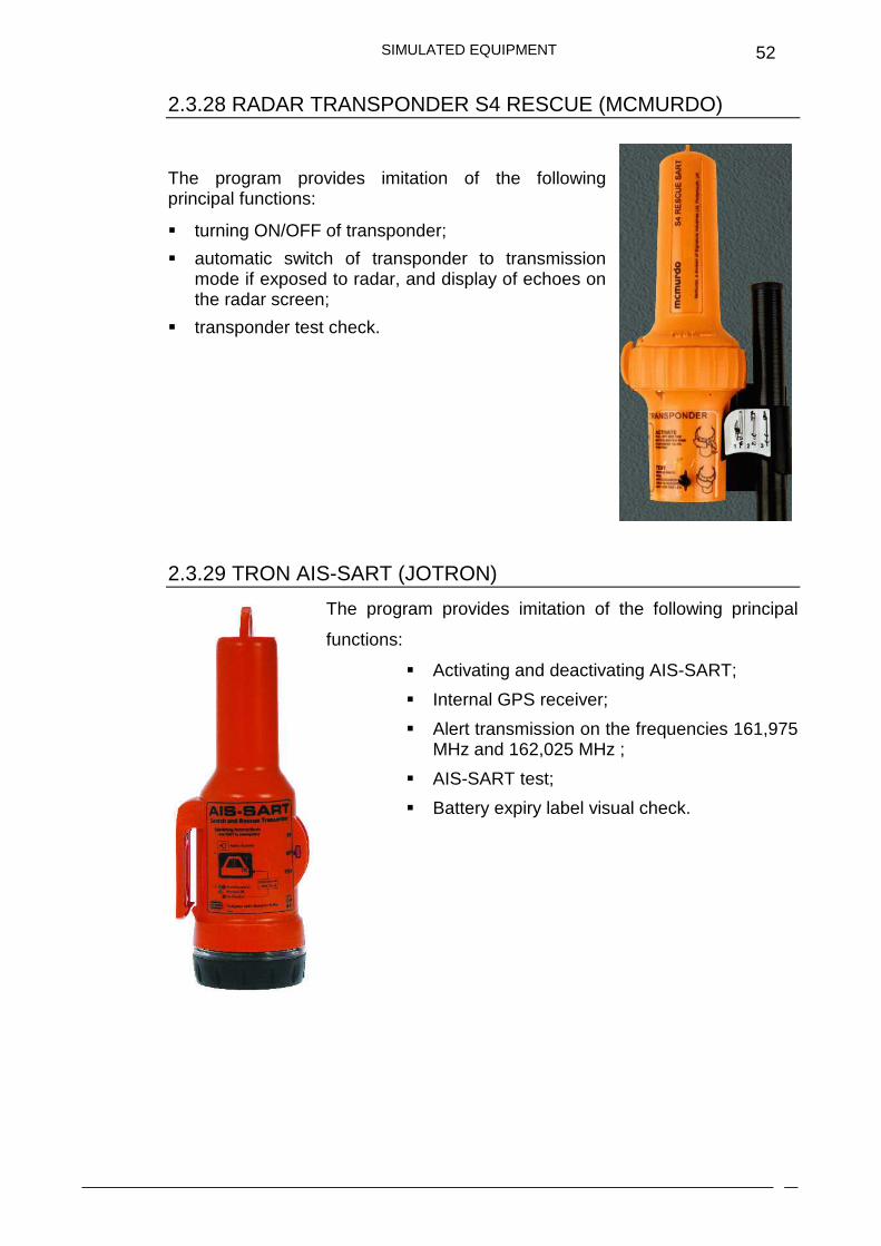
2.3.28 RADAR TRANSPONDER S4 RESCUE (MCMURDO)
The program provides imitation of the following principal functions:
� turning ON/OFF of transponder;
� automatic switch of transponder to transmission mode if exposed to radar, and display of echoes on the radar screen;
� transponder test check.
2.3.29 TRON AIS-SART (JOTRON)
The program provides imitation of the following principal
functions:
� Activating and deactivating AIS-SART;
� Internal GPS receiver;
� Alert transmission on the frequencies 161,975 MHz and 162,025 MHz ;
� AIS-SART test;
� Battery expiry label visual check.
SIMULATED EQUIPMENT
53
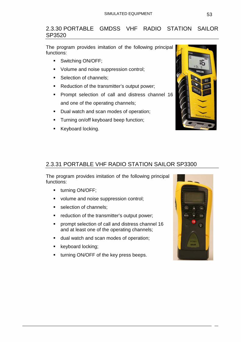
2.3.30 PORTABLE GMDSS VHF RADIO STATION SAILOR SP3520
The program provides imitation of the following principal functions:
� Switching ON/OFF;
� Volume and noise suppression control;
� Selection of channels;
� Reduction of the transmitter’s output power;
� Prompt selection of call and distress channel 16
and one of the operating channels;
� Dual watch and scan modes of operation;
� Turning on/off keyboard beep function;
� Keyboard locking.
2.3.31 PORTABLE VHF RADIO STATION SAILOR SP3300
The program provides imitation of the following principal functions:
� turning ON/OFF;
� volume and noise suppression control;
� selection of channels;
� reduction of the transmitter’s output power;
� prompt selection of call and distress channel 16 and at least one of the operating channels;
� dual watch and scan modes of operation;
� keyboard locking;
� turning ON/OFF of the key press beeps.
SIMULATED EQUIPMENT
54
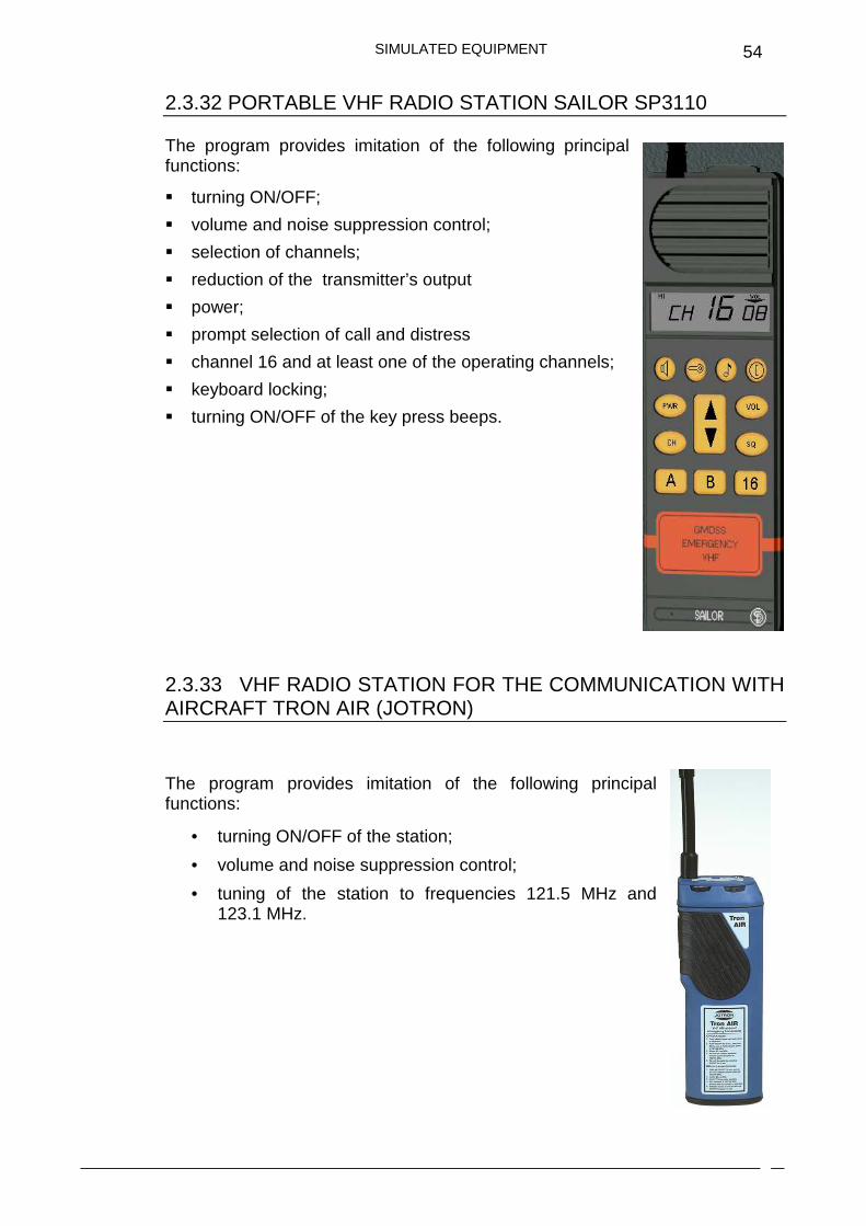
2.3.32 PORTABLE VHF RADIO STATION SAILOR SP3110
The program provides imitation of the following principal functions:
� turning ON/OFF;
� volume and noise suppression control;
� selection of channels;
� reduction of the transmitter’s output
� power;
� prompt selection of call and distress
� channel 16 and at least one of the operating channels;
� keyboard locking;
� turning ON/OFF of the key press beeps.
2.3.33 VHF RADIO STATION FOR THE COMMUNICATION WITH AIRCRAFT TRON AIR (JOTRON)
The program provides imitation of the following principal functions:
• turning ON/OFF of the station;
• volume and noise suppression control;
• tuning of the station to frequencies 121.5 MHz and 123.1 MHz.

SIMULATED EQUIPMENT
55
2.3.34 GPS RECEIVER FURUNO GP-90
The program provides imitation of the following functions:
• turning ON/OFF of the receiver;
• display of ship position, course and speed;
• operation in the following display modes: Plotter 1, Plotter 2, Highway, Navigation and Data;
• Satellite monitor to show position of GPS satellites;
• Beacon receiver monitor to display DGPS beacon station information;
• setting options in accordance with the unit description.
Coordinates, course and speed are sent from the instructor workplace. In addition, the trainee can change the course and speed by using the steering panel.
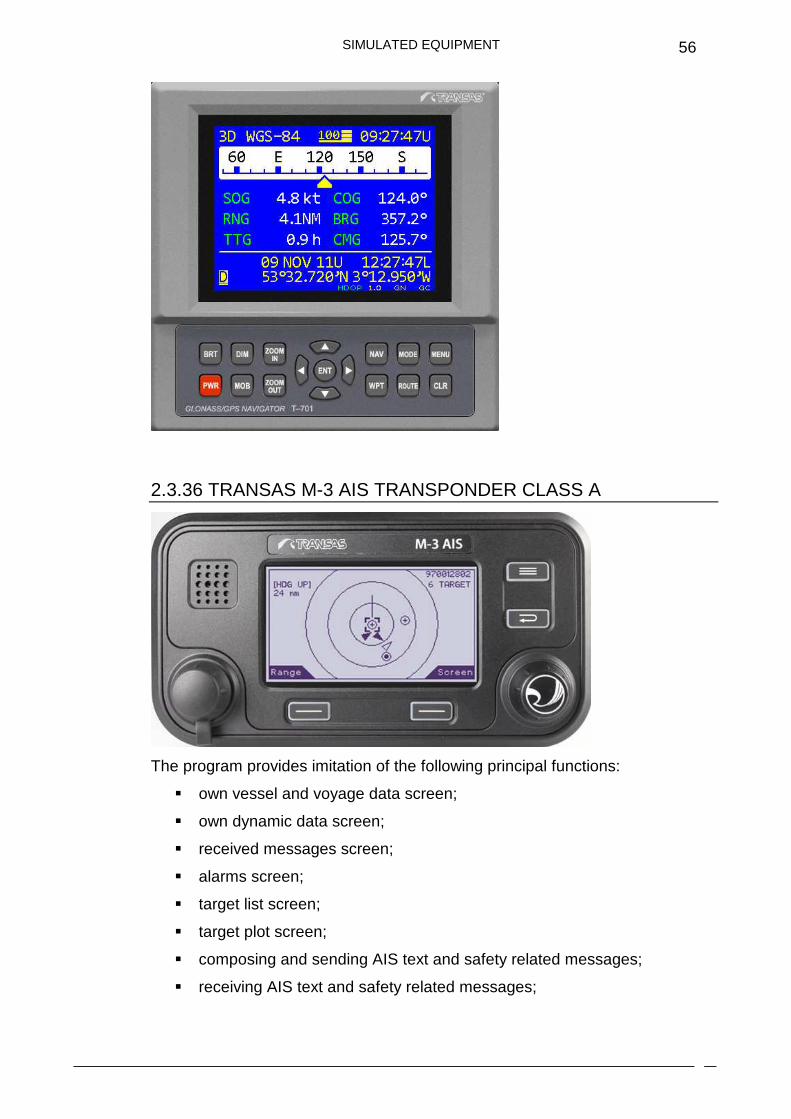
2.3.35 GLONASS/GPS RECEIVER TRANSAS T-701
The program provides imitation of the following principal functions:
• turning ON/OFF;
• Display of ship position, course and speed;
• Operation in the following display modes: Main, Course Deviation Indicator, Satellite, Plotter, Highway;
• Satellite monitor to show position of GPS and Glonass satellites;
• Setting some options in accordance with the unit description.
SIMULATED EQUIPMENT
56
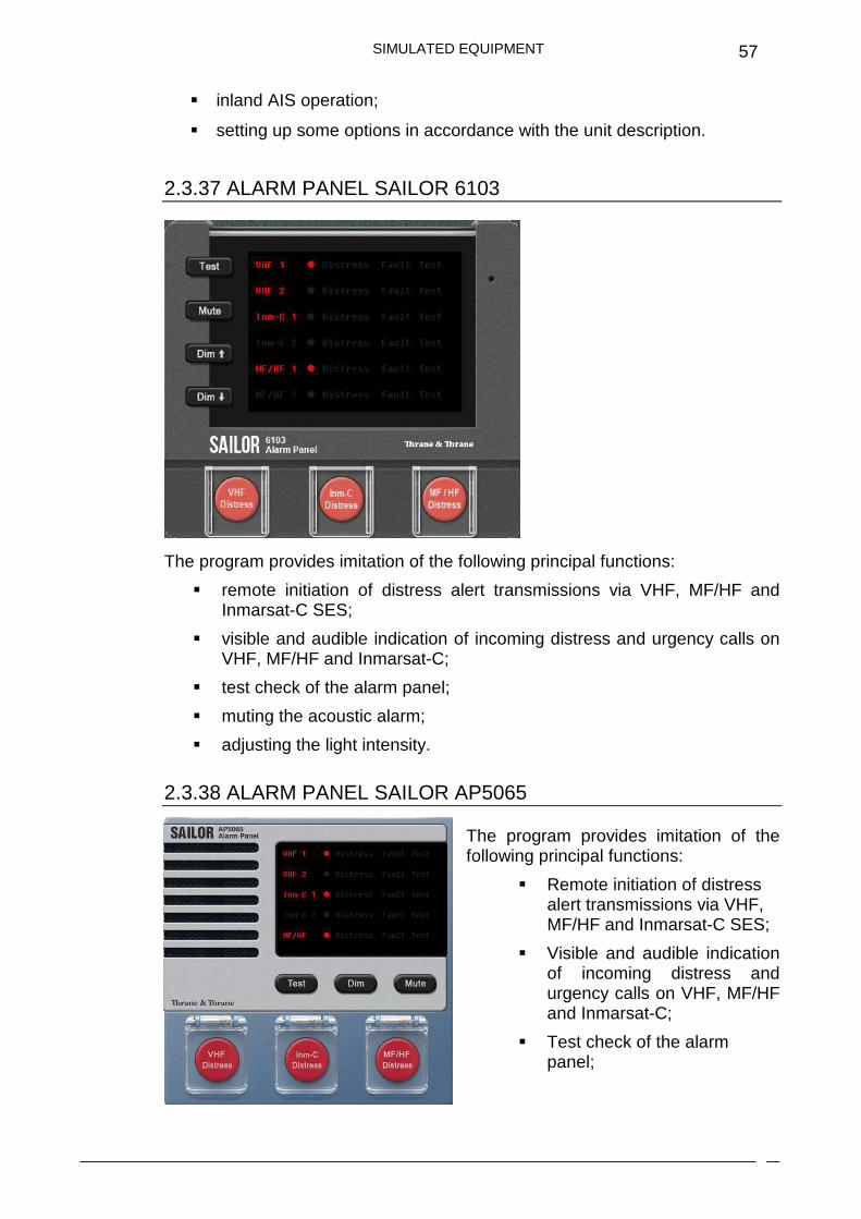
2.3.36 TRANSAS M-3 AIS TRANSPONDER CLASS A
The program provides imitation of the following principal functions:
� own vessel and voyage data screen;
� own dynamic data screen;
� received messages screen;
� alarms screen;
� target list screen;
� target plot screen;
� composing and sending AIS text and safety related messages;
� receiving AIS text and safety related messages;
SIMULATED EQUIPMENT
57
� inland AIS operation;
� setting up some options in accordance with the unit description.
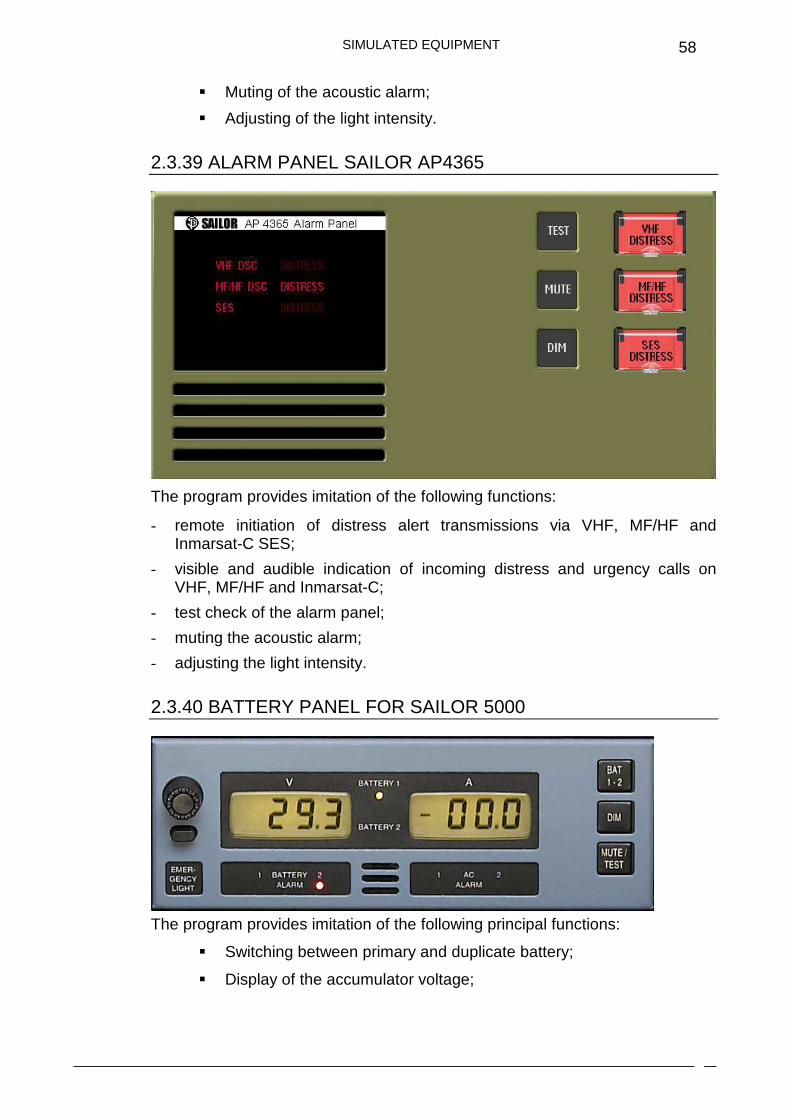
2.3.37 ALARM PANEL SAILOR 6103
The program provides imitation of the following principal functions:
� remote initiation of distress alert transmissions via VHF, MF/HF and Inmarsat-C SES;
� visible and audible indication of incoming distress and urgency calls on VHF, MF/HF and Inmarsat-C;
� test check of the alarm panel;
� muting the acoustic alarm;
� adjusting the light intensity.
2.3.38 ALARM PANEL SAILOR AP5065
The program provides imitation of the following principal functions:
� Remote initiation of distress alert transmissions via VHF, MF/HF and Inmarsat-C SES;
� Visible and audible indication of incoming distress and urgency calls on VHF, MF/HF and Inmarsat-C;
� Test check of the alarm panel;
SIMULATED EQUIPMENT
58
� Muting of the acoustic alarm;
� Adjusting of the light intensity.
2.3.39 ALARM PANEL SAILOR AP4365
The program provides imitation of the following functions:
- remote initiation of distress alert transmissions via VHF, MF/HF and Inmarsat-C SES;
- visible and audible indication of incoming distress and urgency calls on VHF, MF/HF and Inmarsat-C;
- test check of the alarm panel;
- muting the acoustic alarm;
- adjusting the light intensity.
2.3.40 BATTERY PANEL FOR SAILOR 5000
The program provides imitation of the following principal functions:
� Switching between primary and duplicate battery;
� Display of the accumulator voltage;

SIMULATED EQUIPMENT
59
� Display of the charging and discharging current;
� Visual and acoustic alarm in case of voltage drop below the
permissible limit (for both, the main power supply and the battery);
� Muting of the alarm sound;
� Test check of the panel;
� Switching on/off the console light and changing the light intensity by
the dimming potentiometer.
2.3.41 BATTERY PANEL SAILOR BP4680
The program provides imitation of the following functions:
- Switching between primary and duplicate battery;
- display of the accumulator voltage;
- display of the charging and discharging current;
- visual and acoustic alarm in case of voltage drop below a permissible limit (for both, main power supply and battery);
- muting of the alarm sound;
- test check of the panel.
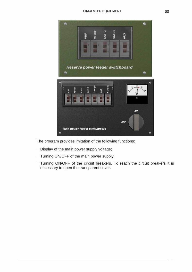
2.3.42 FEEDER SWITCHBOARD
Main and reserve power feeder switchboards are simulated.
SIMULATED EQUIPMENT
60
The program provides imitation of the following functions:
− Display of the main power supply voltage;
− Turning ON/OFF of the main power supply;
− Turning ON/OFF of the circuit breakers. To reach the circuit breakers it is necessary to open the transparent cover.
SIMULATED EQUIPMENT
61
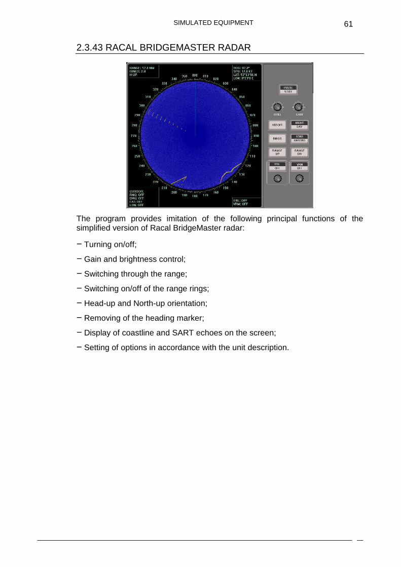
2.3.43 RACAL BRIDGEMASTER RADAR
The program provides imitation of the following principal functions of the simplified version of Racal BridgeMaster radar:
− Turning on/off;
− Gain and brightness control;
− Switching through the range;
− Switching on/off of the range rings;
− Head-up and North-up orientation;
− Removing of the heading marker;
− Display of coastline and SART echoes on the screen;
− Setting of options in accordance with the unit description.
SIMULATED EQUIPMENT
62
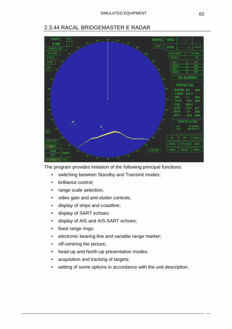
2.3.44 RACAL BRIDGEMASTER E RADAR
The program provides imitation of the following principal functions:
• switching between Standby and Transmit modes;
• brilliance control;
• range scale selection;
• video gain and anti-clutter controls;
• display of ships and coastline;
• display of SART echoes;
• display of AIS and AIS-SART echoes;
• fixed range rings;
• electronic bearing line and variable range marker;
• off-centring the picture;
• head-up and North-up presentation modes;
• acquisition and tracking of targets;
• setting of some options in accordance with the unit description.

SIMULATED EQUIPMENT
63
2.3.45 REMOTE CONTROL PANEL OF CHARGING UNIT SAILOR H2180
The program provides imitation of the following principal functions:
� turning ON/OFF of the charging unit;
� display of the charging current;
� display of the accumulator voltage.
2.3.46 STEERING PANEL
Trainee can change course and speed.
SIMULATED EQUIPMENT
64
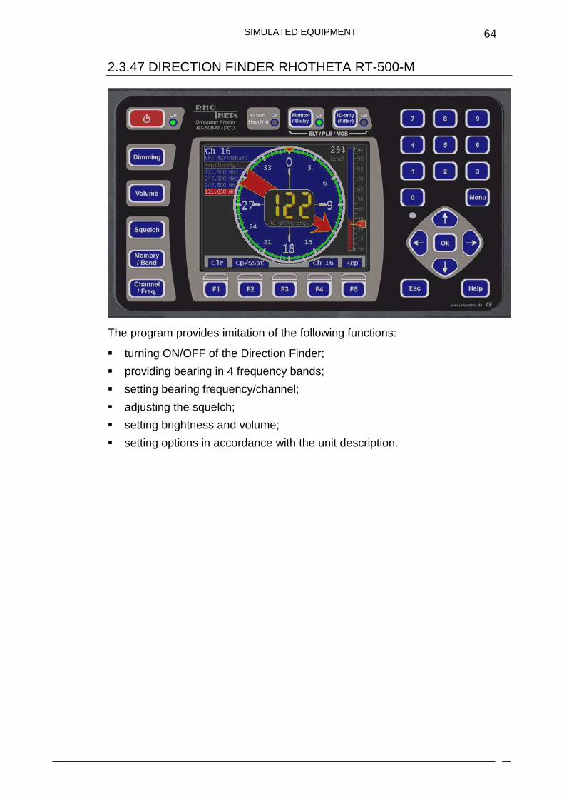
2.3.47 DIRECTION FINDER RHOTHETA RT-500-M
The program provides imitation of the following functions:
� turning ON/OFF of the Direction Finder;
� providing bearing in 4 frequency bands;
� setting bearing frequency/channel;
� adjusting the squelch;
� setting brightness and volume;
� setting options in accordance with the unit description.
SIMULATED EQUIPMENT
65
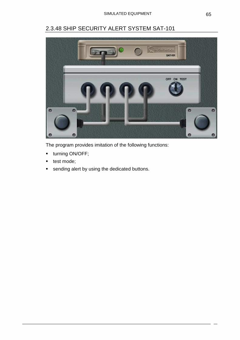
2.3.48 SHIP SECURITY ALERT SYSTEM SAT-101
The program provides imitation of the following functions:
� turning ON/OFF;
� test mode;
� sending alert by using the dedicated buttons.
OPTIONS WINDOW
66
2.4. OPTIONS WINDOW
OPTIONS WINDOW
67
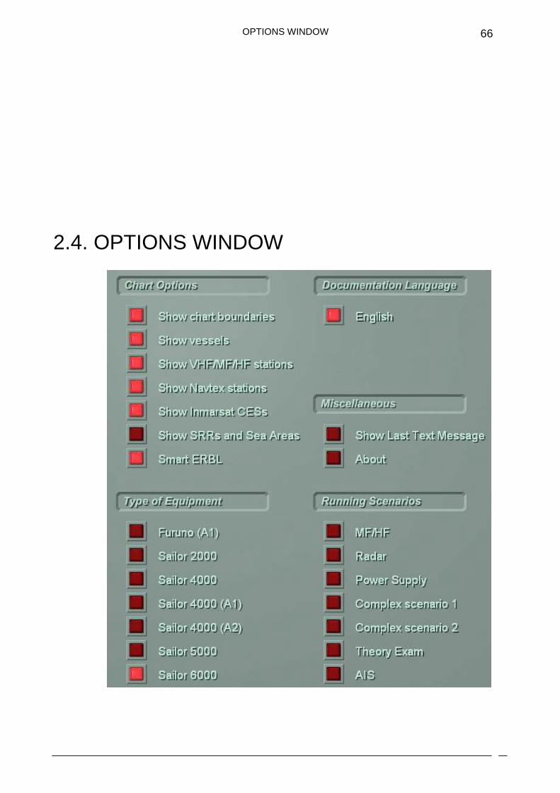
Options window contains the following items:
− Chart Options - to allow the display of objects on the chart.
− Type of equipment - to select the type of equipment in use.
− Running scenarios – to run the prepared scenarios.
CHOICE OF THE SIMULATED RADIO EQUIPMENT
68
2.5. CHOICE OF THE SIMULATED RADIO EQUIPMENT
When Tutor program is started, SAILOR 6000 radio equipment by the Danish company Thrane&Thrane will be selected automatically.
The user can choose SAILOR 5000, SAILOR Programme 4000 and SAILOR Compact 2000 radio equipment. Press Options button and select the required subset. In addition, SAILOR Programme 4000 radio equipment required for Sea Area A1 or A2 only and Furuno radio equipment required for Sea Area A1 can be chosen.
RUNNING THE SCENARIOS
69
2.6. RUNNING THE SCENARIOS
The program includes six prepared scenarios. The list of scenarios is located in the Options window.
The following scenarios are available:
− MF/HF: DSC 'All ships' safety call will be transmitted by a coast station. The user is required to receive safety message in FEC mode and accomplish tasks set by the program.
− Radar scenario: the user is required to detect SART marks on the radar screen and proceed to the distress area.
− Power supply: the goal of the scenario is to become familiar with a visual and acoustic alarm in case of voltage drop below the permissible limit (for both, the main power supply and the battery).
− Complex scenario 1 and 2: the user is required to receive messages and accomplish tasks set by the program.
− Theory exam: the program will display 12 text questions with 30-second intervals. Mark the correct answer and press Accept button. The final result will be displayed on the screen.
− AIS: the goal of the scenario is the reception of the different types of AIS messages.
Only one scenario should be started at a time. Mark the required scenario to run.