Embed Size (px)
Citation preview
TranScan Sentinel User Reference Manual (T510)
UDN1595 Issue A © Seven Telematics 2011 Page 1 of 20
TranScan Sentinel User Reference Manual
Contents
Section Page number 1.0 Introduction
1.1 Product overview 3 1.2 Inputs and outputs 3 1.3 Principle of operation 4 1.4 Main components
1.4.1 The display 4 1.4.2 The operator keys 4 1.4.3 The printer 4
2.0 Getting started
2.1 Language of operation 5 2.2 Journey ticket 5 2.3 Vehicle identifiers 6 2.4 Time and date 6 2.5 Inputs being monitored 6 2.6 Recording process active 6 2.7 Recording interval 6
3.0 Basic operation
3.1 Help printout 7 3.2 Printing a delivery ticket 7 3.3 Printing a Journey ticket 7 3.4 Printing from memory 8 3.5 Display mode 8 3.6 Adjusting the recording interval 8
4.0 Advanced operation
4.1 Printing data from memory 4.1.1 Print file list 9 4.1.2 Print new files 10 4.1.3 Print all files 10 4.1.4 Marking a file 10
4.2 Offloading data to a PC 4.2.1 Print file list 11 4.2.2 Upload new files 11 4.2.3 Upload old files 11 4.2.4 Upload all files 11 4.2.5 Marking a file 11
4.3 Setting user options Language, print direction, recorder type, C/F selection. 12
4.4 Adjusting the time and date 4.4.1 Clock protect 12 4.4.2 Clock adjustment (clock protect not enabled) 12 4.4.3 Clock adjustment (clock protect enabled) 13 4.4.4 Date adjustment 13
TranScan Sentinel User Reference Manual (T510)
UDN1595 Issue A © Seven Telematics 2011 Page 2 of 20
TranScan Sentinel User Reference Manual
Contents
Section Page number 5.0 Configuration parameters
5.1 Printing the parameters 14 5.2 Accessing and adjusting parameters
5.2.1 Product description and sign on message 15 5.2.2 Recording regime 15 5.2.3 Recording interval 15 5.2.4 On/Off input 15 5.2.5 Temperature channels and descriptions 16 5.2.6 Information included in reports 16 5.2.7 Engineering display 16 5.2.8 Vehicle identifiers 17 5.2.9 Signature 17
6.0 Specification 18 7.0 Declaration of conformance 20
Firmware version T510
TranScan Sentinel User Reference Manual (T510)
UDN1595 Issue A © Seven Telematics 2011 Page 3 of 20
1.0 Introduction 1.1 Product Overview TranScan Sentinel has been designed specifically to meet the recommendations of Food Hygiene Regulations with the regard to transport and delivery of chilled and frozen foodstuffs in refrigerated vehicles. TranScan Sentinel is approved to EN 12830 (and other national requirements) meeting the objectives of directives 92/1/EEC and 93/43/EEC. TranScan Sentinel is available in three styles as depicted below :-
Sentinel R for in-cab installation in a standard DIN car radio slot
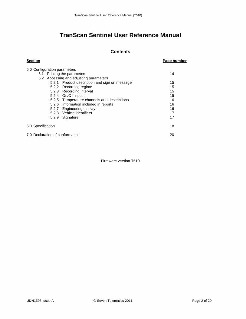
Sentinel C for in-cab installation on a vertical surface or bulkhead
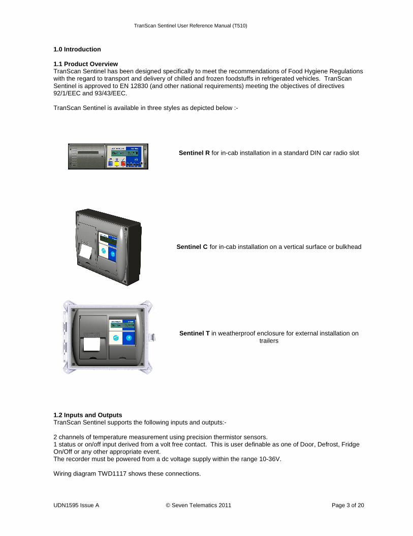
Sentinel T in weatherproof enclosure for external installation on trailers
1.2 Inputs and Outputs TranScan Sentinel supports the following inputs and outputs:- 2 channels of temperature measurement using precision thermistor sensors. 1 status or on/off input derived from a volt free contact. This is user definable as one of Door, Defrost, Fridge On/Off or any other appropriate event. The recorder must be powered from a dc voltage supply within the range 10-36V. Wiring diagram TWD1117 shows these connections.
TranScan Sentinel User Reference Manual (T510)
UDN1595 Issue A © Seven Telematics 2011 Page 4 of 20
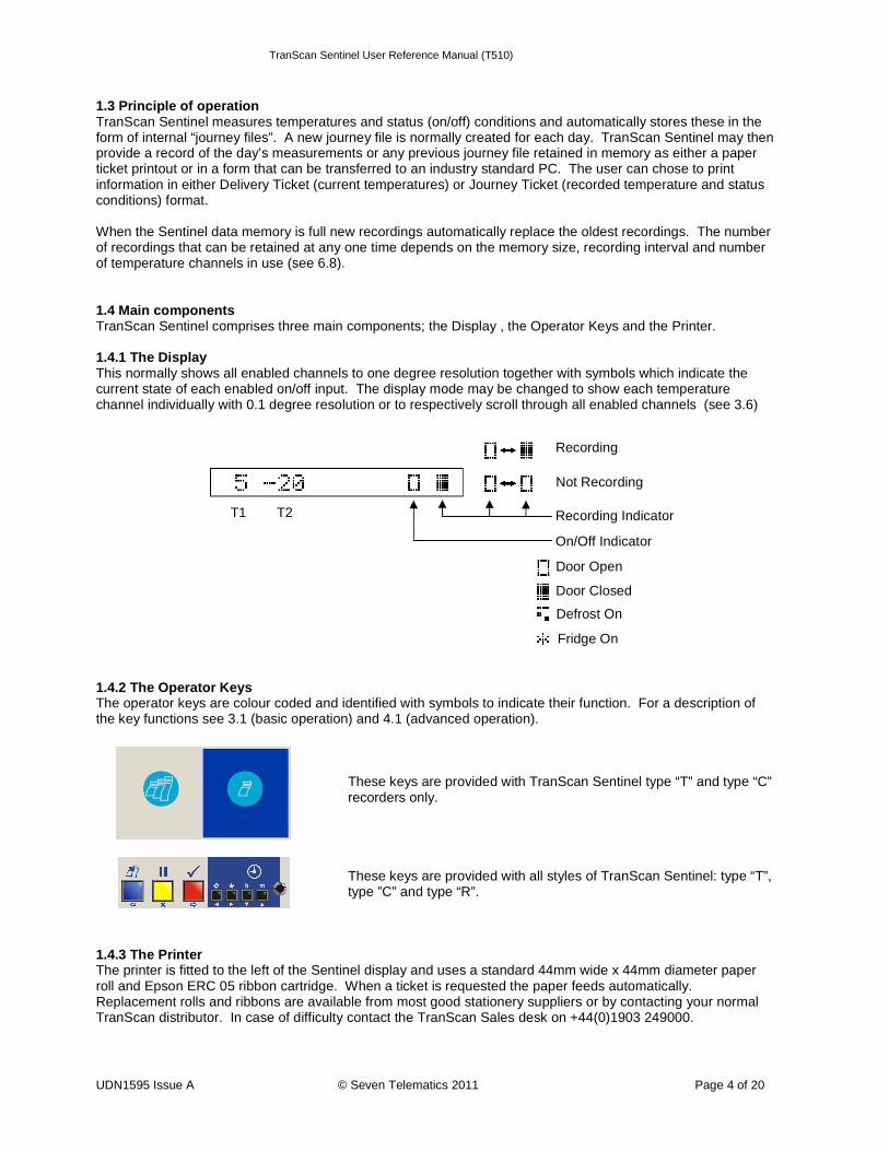
1.3 Principle of operation TranScan Sentinel measures temperatures and status (on/off) conditions and automatically stores these in the form of internal “journey files”. A new journey file is normally created for each day. TranScan Sentinel may then provide a record of the day’s measurements or any previous journey file retained in memory as either a paper ticket printout or in a form that can be transferred to an industry standard PC. The user can chose to print information in either Delivery Ticket (current temperatures) or Journey Ticket (recorded temperature and status conditions) format. When the Sentinel data memory is full new recordings automatically replace the oldest recordings. The number of recordings that can be retained at any one time depends on the memory size, recording interval and number of temperature channels in use (see 6.8). 1.4 Main components TranScan Sentinel comprises three main components; the Display , the Operator Keys and the Printer. 1.4.1 The Display This normally shows all enabled channels to one degree resolution together with symbols which indicate the current state of each enabled on/off input. The display mode may be changed to show each temperature channel individually with 0.1 degree resolution or to respectively scroll through all enabled channels (see 3.6) 1.4.2 The Operator Keys The operator keys are colour coded and identified with symbols to indicate their function. For a description of the key functions see 3.1 (basic operation) and 4.1 (advanced operation).
These keys are provided with TranScan Sentinel type “T” and type “C” recorders only.
These keys are provided with all styles of TranScan Sentinel: type “T”, type ”C” and type “R”.
1.4.3 The Printer The printer is fitted to the left of the Sentinel display and uses a standard 44mm wide x 44mm diameter paper roll and Epson ERC 05 ribbon cartridge. When a ticket is requested the paper feeds automatically. Replacement rolls and ribbons are available from most good stationery suppliers or by contacting your normal TranScan distributor. In case of difficulty contact the TranScan Sales desk on +44(0)1903 249000.
Recording
Not Recording
Recording Indicator
On/Off Indicator
Door Open
Door Closed
Defrost On
T1 T2
Fridge On
TranScan Sentinel User Reference Manual (T510)
UDN1595 Issue A © Seven Telematics 2011 Page 5 of 20
2.0 Getting Started See also 3.1 “Help Printout” Before operating your Sentinel recorder for the first time check that is it set to operate to your requirements by carrying out a few simple checks in the following order:- 2.1 Set the Language of Operation Press and h together and the Display shows Set User Options Press and the Display shows the language selected TranScan Sentinel is factory set to English. If this is acceptable Press to return to the normal Display. If a different language is required Press to step through the alternatives available
English Francais Deutsch Nederlands Espaîol Portugu es Italiano
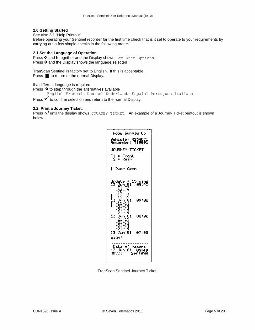
Press to confirm selection and return to the normal Display. 2.2. Print a Journey Ticket. Press until the display shows JOURNEY TICKET. An example of a Journey Ticket printout is shown below:-
TranScan Sentinel Journey Ticket
TranScan Sentinel User Reference Manual (T510)
UDN1595 Issue A © Seven Telematics 2011 Page 6 of 20
2.3 Check the Vehicle Identifiers Check that the Title and Vehicle descriptions are set correctly. The Title is a total of 16 characters that is usually set to the vehicle operator’s company name and is printed on the first line of each report. This is factory set to “Company Name”. The Vehicle number is an 8 character descriptor normally used for the registration number or trailer number. It is factory set to AB51 CDE for type “C” and “R” recorders and TRL 1234 for type “T” recorders. To change the Title and Vehicle descriptions see 5.2.8. 2.4 Check the Time and Date The time and date which are printed at the end of the Journey and Delivery Ticket are factory set to GMT immediately prior to despatch from the factory. Once set the Date should never need adjusting during the lifetime of the recorder. The clock includes automatic adjustment for winter/summer time. This automatically adds one hour to the set time between 2:00am on the last Sunday in March and 2:00am on the last Sunday in October. To check the clock time and date press h. To adjust the time and/or date see 4.4 and 5.2.7 NOTE : When the time or date are changed a new recording is started and the message NEW FILE will appear on the display. 2.5 Check that all required inputs are being monitored. TranScan Sentinel supports up to 2 temperature channels and 1 on/off input but the most applications call for two temperature channels only. Inspect the Journey Ticket printout taken and compare with the example above to determine how many temperature channels your recorder is monitoring. Examine the display (see 1.4.1) to determine if door or defrost monitoring is enabled by reference to the relevant symbols. Exercise this input (e.g. by opening and closing the compartment door) to check that the input sensor is working correctly by checking that the symbol on the display changes accordingly. 2.6 Check that recordings are being made TranScan Sentinel is factory set to record continuously 24 hours a day 7 days a week. Data is recorded in separate complete 24 hour periods, or daily files, for ease of access. This is known as Automatic Daily Recording (ADR) and is a unique TranScan process. Although many different recording regimes are possible this standard setting is very widely used and normally no driver action or adjustment is required to start or stop the recording process. Use the display (see 1.4.1) to check that recording is in progress. 2.7 Check the Recording Interval TranScan Sentinel is factory set to record every 15 minutes. To check the recording interval Press and the Display will show the recording interval in minutes. To change the recording interval Press and the Display shows PAUSING Press to show the recording interval selected Press to step through the alternatives available (5, 15, or 30 mins)
Press to confirm selection and return to the normal Display. NOTE : When recording interval is changed a new recording is started and the message NEW FILE will appear on the display.
TranScan Sentinel User Reference Manual (T510)
UDN1595 Issue A © Seven Telematics 2011 Page 7 of 20
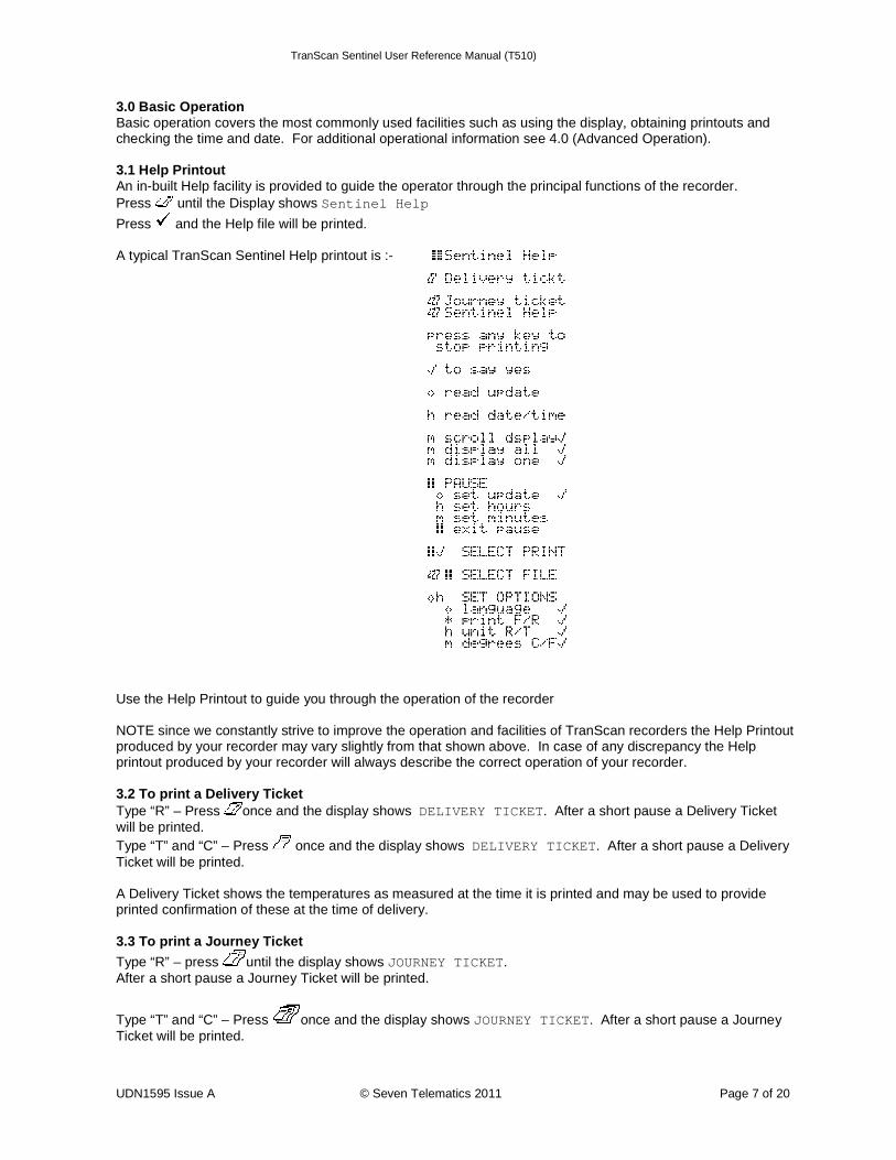
3.0 Basic Operation Basic operation covers the most commonly used facilities such as using the display, obtaining printouts and checking the time and date. For additional operational information see 4.0 (Advanced Operation). 3.1 Help Printout An in-built Help facility is provided to guide the operator through the principal functions of the recorder. Press until the Display shows Sentinel Help
Press and the Help file will be printed. A typical TranScan Sentinel Help printout is :- Use the Help Printout to guide you through the operation of the recorder NOTE since we constantly strive to improve the operation and facilities of TranScan recorders the Help Printout produced by your recorder may vary slightly from that shown above. In case of any discrepancy the Help printout produced by your recorder will always describe the correct operation of your recorder. 3.2 To print a Delivery Ticket Type “R” – Press once and the display shows DELIVERY TICKET . After a short pause a Delivery Ticket will be printed. Type “T” and “C” – Press once and the display shows DELIVERY TICKET . After a short pause a Delivery Ticket will be printed. A Delivery Ticket shows the temperatures as measured at the time it is printed and may be used to provide printed confirmation of these at the time of delivery. 3.3 To print a Journey Ticket
Type “R” – press until the display shows JOURNEY TICKET. After a short pause a Journey Ticket will be printed.
Type “T” and “C” – Press once and the display shows JOURNEY TICKET. After a short pause a Journey Ticket will be printed.
TranScan Sentinel User Reference Manual (T510)
UDN1595 Issue A © Seven Telematics 2011 Page 8 of 20
3.4 To print any file from memory TranScan Sentinel stores data as Journey Files each of which normally cover a complete 24 hour period. Other types of recording regime are possible to cover specific requirements (see 5.2.2). TranScan data memory is battery backed and data is retained with or without power for a minimum of 5 years. Individual Journey Files may be printed from memory as often as required. See 4.2 for further information about printing data from memory and see 6.8 for a description of memory size and data storage capacity. 3.5 To set the display mode The TranScan Sentinel display can be set to any of the following options:- Summary display All enabled temperature channels are displayed simultaneously (resolution 1.0 degree) together with symbols representing the enabled on/off inputs. This is the factory default setting. Single display One selected enabled temperature channel is displayed individually (resolution 0.1 degrees) together with its name. This is useful when undertaking a temperature verification or reference check on an individual temperature channel. Scroll display This shows each enabled channel plus the summary display in turn. To change the display mode. Press m and the display shows scroll display. Press m to show the summary. Press m to step through the individual temperature channels enabled.
Press at any time to confirm your choice. For more information concerning the display symbols and their meaning see 1.4.1. 3.6 To check and adjust the recording interval TranScan Sentinel is factory set to record every 15 minutes. To check the recording interval Press and the Display will show the recording interval in minutes. To change the recording interval Press and the Display shows PAUSING Press to show the recording interval selected Press to step through the alternatives available (5, 15, 30 mins)
Press to confirm selection and return to the normal Display. NOTE : When recording interval is changed a new recording is started and the message NEW FILE will appear on the display.
TranScan Sentinel User Reference Manual (T510)
UDN1595 Issue A © Seven Telematics 2011 Page 9 of 20
4.0 Advanced Operation Advanced operation covers the less commonly used facilities such as selecting data from memory and printing it, offloading data to a Data Collection Unit or PC, setting user options and adjusting the time and date. For basic operational information see 3.0 (Basic Operation). 4.1 Printing Data from memory (Select Printout) It is possible to print a list of all files stored in the Sentinel data memory, mark a file to identify those that have been printed (subsequent recordings are then identified as “New”), print all files contained in memory or select and print one or more files.
Press and together and the display shows Select printout Press to scroll through the following options
Print file list Print new files Print all files DD MM hh:mm (then use h to move back through older recordings and m to move forwards through
newer ones) DD MM hh:mm is the date and start time of the most recent recording in memory. For standard Sentinel operation this will be the current date with a start time of 00:00 (midnight).
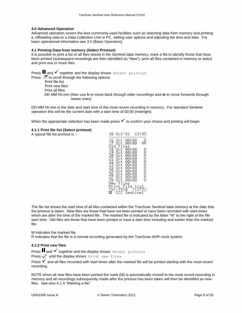
When the appropriate selection has been made press to confirm your choice and printing will begin. 4.1.1 Print file list (Select printout) A typical file list printout is :- The file list shows the start time of all files contained within the TranScan Sentinel data memory at the date that the printout is taken. New files are those that have not been printed or have been recorded with start times which are after the time of the marked file. The marked file is indicated by the letter “M” to the right of the file start time. Old files are those that have been printed or have a start time including and earlier than the marked file. M indicates the marked file R indicates that the file is a normal recording generated by the TranScan ADR clock system. 4.1.2 Print new files
Press and together and the display shows Select printout Press until the display shows Print new files
Press and all files recorded with start times after the marked file will be printed starting with the most recent recording. NOTE when all new files have been printed the mark (M) is automatically moved to the most recent recording in memory and all recordings subsequently made after the printout has been taken will then be identified as new files. See also 4.1.4 “Marking a file”
TranScan Sentinel User Reference Manual (T510)
UDN1595 Issue A © Seven Telematics 2011 Page 10 of 20
4.1.3 Print all files
Press and together and the display shows Select printout Press until the display shows Print all files
Press and all files in memory will be printed starting with the most recent recording. NOTE when all files have been printed the mark (M) is automatically moved to the most recent recording in memory and all recordings subsequently made after the printout has been taken will then be identified as new files. See also 4.1.4 “Marking a file” 4.1.4 Marking a file
Press and together and the display shows Select printout Press until the display shows the date and time of the most recent recording in memory. Press h to move back through older recordings and m to move forwards through newer ones and then press or to mark a chosen file. NOTE:- the marking of files for printing data from memory is completely independent of that when offloading recordings to a Data Collection Unit or PC (see 4.2.5). 4.2 Offloading data to a computer (Select filedump) Data recorded by the TranScan Sentinel may be offloaded for archiving on an office computer. TranScan supply a Data Collection Unit (DCU) and software for this purpose. Alternatively a PC running TranScan Data Management software may be connected directly to the Sentinel. Offloading data is a copying process and does not remove or delete data from the Sentinel data memory. NOTE:- Data is offloaded through the communications socket located on the front fascia of the TranScan Sentinel (see 1.4.2) using a lead and jack plug to connect to a DCU or PC running software supplied by TranScan For further information concerning data offloading, compatible equipment and software contact the TranScan Sales Desk or your accredited TranScan dealer.
Press and together and the display shows Select filedump Press to scroll through the following options
Upload file list Upload new files Upload old files Upload all files DD MM hh:mm (then use h to move back through older recordings and m to move forwards through
newer ones) DD MM hh:mm is the date and start time of the most recent recording in memory. For standard TranScan Sentinel operation this will be the current date with a start time of 00:00 (midnight).
When the appropriate selection has been made press to confirm choice and offloading will begin.
TranScan Sentinel User Reference Manual (T510)
UDN1595 Issue A © Seven Telematics 2011 Page 11 of 20
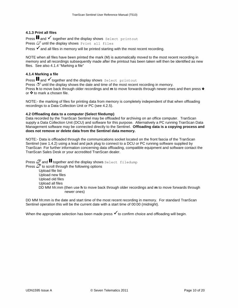
4.2.1 Print file list (Select filedump) A typical file list printout is:- The file list shows the start time of all files contained within the TranScan data memory at the date that the printout is taken. New files are those that have not been offloaded or have been recorded with start times which are after the time of the marked file. The marked file is indicated by the letter “X” to the right of the file start time. Old files are those that have been offloaded or have a start time including and earlier than the marked file. X indicates the marked file R indicates that the file is a normal recording generated by the Sentinel ADR clock system. 4.2.2 Upload new files
Press and together and the display shows Select filedump Press until the display shows Upload new files
Press and all files recorded with start times after the marked file will be offloaded starting with the most recent recording. NOTE when all new files have been offloaded the mark (X) is automatically moved to the most recent recording in memory and all recordings subsequently made after the offload will then be identified as new files. See also 4.2.5 “Marking a file” 4.2.3 Upload old files
Press and together and the display shows Select filedump Press until the display shows Upload old files
Press and all files recorded with start times earlier than the marked file will be offloaded starting with the marked file. Offloading old files does not alter the marked file. 4.2.4 Upload all files
Press and together and the display shows Select filedump Press until the display shows Upload all files
Press and all files in memory will be offloaded starting with the most recent recording. NOTE when all files have been offloaded the mark (X) is automatically moved to the most recent recording in memory and all recordings subsequently made after the offload will then be identified as new files. See also 4.2.5 “Marking a file” 4.2.5 Marking a file
Press and together and the display shows Select filedump Press until the display shows the date and time of the most recent recording in memory. Press h to move back through older recordings and m to move forwards through newer ones and then press or to mark a chosen file.
TranScan Sentinel User Reference Manual (T510)
UDN1595 Issue A © Seven Telematics 2011 Page 12 of 20
NOTE:- the marking of files for offloading data to a Data Collection Unit or PC is completely independent from marking files for printing data from memory (see 4.2.4). 4.3 Setting user options It is possible to customise the operation of the TranScan Sentinel through the User Options feature. To review or change the User Options for a recorder Press and h together and the display shows Set User Options Press to select the operator language English Francais Deutsch Nederlands Espaîol Portug ues Italiano Press to select the print direction as FORWARD or REVERSE Press h to select recorder type as R or T. Select R for type “R” recorders Select T for type “T” and type “C” recorders. Press m to select operation in C or F
In all cases press to confirm a choice from the options available.
The and keys return the recorder to the normal operating display. Journey tickets may be printed in a forward or reverse direction as determined by the selected print direction. The results look similar but timed data is always printed in the reverse time direction (most recent first) independently of the direction of printing. The default settings for print direction are: Type “T”/”C” – REVERSE direction Type “R” – FORWARD direction.
These settings ensure that printed data emerges from the printer with the text readable as it is being printed (ie not upside down). However this will result in the data being presented differently when comparing printouts produced by type “R” recorders with those produced by type “T” / “C” recorders. If the direction of data on printouts is important for ease of comparing recordings printed by type “R” recorders with those printed by type “T” /”C” recorders then it will be necessary to set the print direction the same for both types. 4.4 Adjusting the time and date The time and date are factory set to GMT prior to despatch from the factory. Once set the Date should never need adjusting during the lifetime of the recorder. The clock includes automatic adjustment for winter/summer time. This automatically adds one hour to the set time between 2:00am on the last Sunday in March and 2:00am on the last Sunday in October (see 5.2.7). 4.4.1 Clock protect Adjustment of the real time clock maybe security protected by the Configuration Parameter ‘Clk Protect’. This is factory set to OFF but maybe set to ON to prevent unauthorised adjustment of the time. To check if the clock protect is enabled
Press and the display shows PAUSING Press h or m and if the clock protect is enabled the display shows Protected. When the clock protect is enabled the clock can only be adjusted by using the PIN protected Configuration Mode. See 4.4.3 4.4.2 Clock adjustment (clock protect not enabled) When the clock protect is not enabled (see 4.4.1)
Press and the display shows PAUSING Press h to adjust hours and m to adjust minutes
TranScan Sentinel User Reference Manual (T510)
UDN1595 Issue A © Seven Telematics 2011 Page 13 of 20
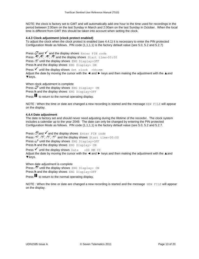
NOTE: the clock is factory set to GMT and will automatically add one hour to the time used for recordings in the period between 2:00am on the last Sunday in March and 2:00am on the last Sunday in October. When the local time is different from GMT this should be taken into account when setting the clock. 4.4.3 Clock adjustment (clock protect enabled) To adjust the clock when the clock protect is enabled (see 4.4.1) it is necessary to enter the PIN protected Configuration Mode as follows. PIN code (1,1,1,1) is the factory default value (see 5.0, 5.2 and 5.2.7)
Press and and the display shows Enter PIN code Press , , , and the display shows Start time>00:00 Press until the display shows ENG Display>OFF Press h and the display shows ENG Display> ON
Press until the display shows Set clock >hh:mm Adjust the date by moving the cursor with the ◄ and ► keys and then making the adjustment with the ▲and ▼keys. When clock adjustment is complete Press until the display shows ENG Display> ON Press h and the display shows ENG Display>OFF
Press to return to the normal operating display. NOTE : When the time or date are changed a new recording is started and the message NEW FILE will appear on the display. 4.4.4 Date adjustment The date is factory set and should never need adjusting during the lifetime of the recorder. The clock system includes a calendar up to the year 2049. The date can only be changed by entering the PIN protected Configuration Mode as follows. PIN code (1,1,1,1) is the factory default value (see 5.0, 5.2 and 5.2.7.
Press and and the display shows Enter PIN code Press , , , and the display shows Start time>00:00 Press until the display shows ENG Display>OFF Press h and the display shows ENG Display> ON
Press until the display shows Date >DD MM YY Adjust the date by moving the cursor with the ◄ and ► keys and then making the adjustment with the ▲and ▼keys. When date adjustment is complete Press until the display shows ENG Display> ON Press h and the display shows ENG Display>OFF
Press to return to the normal operating display. NOTE : When the time or date are changed a new recording is started and the message NEW FILE will appear on the display.
TranScan Sentinel User Reference Manual (T510)
UDN1595 Issue A © Seven Telematics 2011 Page 14 of 20
5.0 Configuration Parameters TranScan Sentinel has been designed to allow a number of variations in the way it operates. This is provided by the configuration parameters and how they are set. Sentinel recorders are normally supplied as a kit that includes appropriate components for the application concerned and the configuration parameters are set accordingly. Entry to Configuration Mode is password protected to prevent unauthorised adjustment. When the correct sequence of keys is pressed Configuration Mode is entered and each parameter is then presented on the display one at a time. The user can step through each parameter and make modifications as necessary. In order to enter Configuration Mode a PIN code is required. To enter the PIN code each of the operator keys is associated with a number as follows:-
= 1, =2, =3, =4, =5, h = 6, m = 7. 5.1 Printing the parameters Before attempting to adjust any of the configuration parameters it is recommended that a printout of the parameters is taken.
Press and together and the display shows Enter PIN code
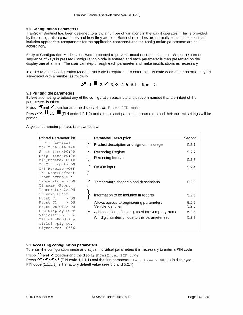
Press , , , (PIN code 1,2,1,2) and after a short pause the parameters and their current settings will be printed. A typical parameter printout is shown below:-
Printed Parameter list Parameter Description Section CCI Sentinel TS2-T510.010-128 Start time>00:00 Stop time>00:00 min/update> 0010 On/Off input> ON I/P Reverse >OFF I/P Name>Defrost Input symbol> * Temperature1> ON T1 name >Front Temperature2> ON T2 name >Rear Print T1 > ON Print T2 > ON Print On/Off> ON ENG Display >OFF Vehicle>TRL 1234 Title1 >Food Sup Title2 >ply Co. Signature: 0556
Product description and sign on message Recording Regime
Recording Interval
On /Off input
Temperature channels and descriptions
Information to be included in reports Allows access to engineering parameters Vehicle Identifier
Additional identifiers e.g. used for Company Name
A 4 digit number unique to this parameter set
5.2.1
5.2.2
5.2.3
5.2.4
5.2.5
5.2.6
5.2.7 5.2.8
5.2.8
5.2.9
5.2 Accessing configuration parameters To enter the configuration mode and adjust individual parameters it is necessary to enter a PIN code
Press and together and the display shows Enter PIN code Press , , , (PIN code 1,1,1,1) and the first parameter Start time > 00:00 is displayed. PIN code (1,1,1,1) is the factory default value (see 5.0 and 5.2.7)
TranScan Sentinel User Reference Manual (T510)
UDN1595 Issue A © Seven Telematics 2011 Page 15 of 20
The operating keys have the following functions in configuration mode
steps to the previous parameter ����
exits configuration mode ���� steps to the next parameter ����
shifts cursor one place left ◄ shifts cursor one place right ►
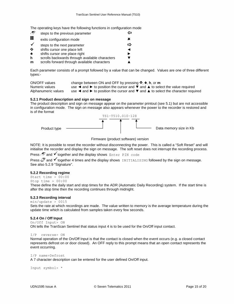
h scrolls backwards through available characters ▼ m scrolls forward through available characters ▲ Each parameter consists of a prompt followed by a value that can be changed. Values are one of three different types:- ON/OFF values change between ON and OFF by pressing , , h, or m Numeric values use ◄ and ► to position the cursor and ▼ and ▲ to select the value required Alphanumeric values use ◄ and ► to position the cursor and ▼ and ▲ to select the character required 5.2.1 Product description and sign on message The product description and sign on message appear on the parameter printout (see 5.1) but are not accessible in configuration mode. The sign on message also appears whenever the power to the recorder is restored and is of the format
TS1-T510.010-128
NOTE: It is possible to reset the recorder without disconnecting the power. This is called a “Soft Reset” and will initialise the recorder and display the sign on message. The soft reset does not interrupt the recording process.
Press and together and the display shows Enter PIN code
Press and together 4 times and the display shows INITIALISING followed by the sign on message. See also 5.2.9 “Signature”. 5.2.2 Recording regime Start time > 00:00 Stop time > 00:00 These define the daily start and stop times for the ADR (Automatic Daily Recording) system. If the start time is after the stop time then the recording continues through midnight. 5.2.3 Recording interval min/update > 0015 Sets the rate at which recordings are made. The value written to memory is the average temperature during the update time which is calculated from samples taken every few seconds. 5.2.4 On / Off Input On/Off Input> ON ON tells the TranScan Sentinel that status input 4 is to be used for the On/Off input contact. I/P reverse> ON Normal operation of the On/Off Input is that the contact is closed when the event occurs (e.g. a closed contact represents defrost on or door closed). An OFF reply to this prompt means that an open contact represents the event occurring. I/P name>Defrost A 7 character description can be entered for the user defined On/Off input. Input symbol> *
Data memory size in Kb
Firmware (product software) version
Product type
TranScan Sentinel User Reference Manual (T510)
UDN1595 Issue A © Seven Telematics 2011 Page 16 of 20
A symbol can be selected from the display character set for the user defined on/off input. There are also special symbols representing a door, defrost and fridge (see 1.4.1). 5.2.5 Temperature channels and descriptions Temperature1> ON Temperature 1 input (T1) will be measured and displayed when set to ON. An OFF reply to this prompt will turn the measurement off and there will be no display for T1 on the display or in reports. T1 name >Air Ret The name of T1 is shown on the display and in reports. A 7 character description can be used. The second temperature input (T2) is similarly programmed. 5.2.6 Information to be included in reports Print T1 > ON Print T2 > ON Print On/Off> ON It is possible to define which inputs are printed on reports and in order to appear on the printout the relevant parameter must be set to ON. Only activate those inputs which are being monitored. 5.2.7 Engineering Display ENG Display >OFF This parameter is normally set to OFF. An ON value allows the following parameters to be displayed R standard> 9090 This is a standard calibration constant for the TranScan. This constant must not be modified. T1 cal val> 2252 This is the standard calibration value for the thermistor probes supplied for use with TranScan recorders. This value must not be modified. The second temperature input (T2) is similarly programmed. PIN number> 1111 (Factory default value) The PIN can consist of any digits in the range 1-7. Setting a PIN of 0000 has the effect of not requiring a PIN code to be entered in order to access the Configuration parameters. WARNING If the PIN is changed, access to parameters will be denied unless the new PIN code is entered correctly. See 5.0, 5.1 and 5.2 Unit I/D> T12345 This is an individual 6 character identifier which is always set to the serial number of the recorder. The identifier is recorded with the data. The unit I/D is printed on line 3 of each report. Please refer to your TranScan dealer if you need to change this parameter. Baud Rate > 9600 This is the speed of communication when the recorder is connected to a PC or other device via the serial port. Date >15 Oct‘01 Adjust the date by moving the cursor with the ◄ and ► keys and then making the adjustment with the ▲and ▼keys. Invalid dates cannot be set. Set clock >12:00 Adjust the clock by moving the cursor with the ◄ and ► keys and then making the adjustment with the ▲and ▼keys. Auto Clk Adj> ON Set this parameter to ON to automatically adjust the time by one hour at 2:00 am on the last Sunday in March (add 1 hour) and 2:00 am on the last Sunday in October (subtract 1 hour). Clk Protect >OFF
TranScan Sentinel User Reference Manual (T510)
UDN1595 Issue A © Seven Telematics 2011 Page 17 of 20
When this parameter is set to OFF it is possible to adjust the clock without the need to enter Configuration Mode
by pressing and using the h and m keys (see 4.4.3). 5.2.8 Vehicle identifiers Vehicle>TRL 1234 A 8 character identifier which may be used to identify the vehicle registration or trailer ID number and which is printed on the second line of each report. Title 1>XXXXXXXX Title 2>XXXXXXXX A further two 8 character identifiers which are used together to specify a user defined 16 character title line which is printed as line 1 of each report. 5.2.9 Signature This is a four digit number which uniquely characterises the current settings of the configuration parameters. The signature does not depend on any of the descriptive names which may be specified as parameter values. NOTE: the signature may be inspected without the need for taking a parameter printout by viewing it on the display. This is useful when a quick comparison between a number of recorders is required in order to establish if their parameter settings are identical.
Press and together and the display shows Enter PIN code Press and h together and the signature will be shown on the display for a few seconds. Recorders with identical firmware (product software) and different signatures have different parameter settings. To check the firmware of the recorder see 5.2.1 “Product description and sign on message”.
TranScan Sentinel User Reference Manual (T510)
UDN1595 Issue A © Seven Telematics 2011 Page 18 of 20
6.0 Specification TranScan temperature recorders are designed to meet the requirements of EN12830 and other national requirements to support the objectives of directives 92/1/EEC (amended by 93/43/EEC) -usually known as the Quick Frozen Food Directive. 6.1 Type of application Suitable for recording storage temperatures. Suitable for recording transport temperatures. 6.2 Measuring range Certified range -30 °C to +30 °C For Germany -35 °C to +25 °C Available range -50 °C to +50 °C 6.3 Autonomous power Lithium Thionyl Chloride ½ AA battery gives 10 year unpowered retention of data and time/date. The battery is not user replaceable. 6.4 Protection IP65 for Trailer models, IP20 for Rigid models. The recorder but not the internal printer in the Rigid model is protected to IP22. In the event of the printer being subject to drips or spillage, it should be allowed to dry out before use. In order to ensure that a printout may be made on demand, a spare printer roll should be carried at all times. 6.5 Supply Voltage DC 10 V to 32 V. The DC supply shall be either from a vehicle battery fused in-line with a Bussmann type TDS501-2 A (or equivalent T2A fuse approved to EN60127) or from an approved mains operated SELV power supply rated for 3A minimum and limited to 100 VA maximum output. The mains operated power supply should be suitable for IEC installation category II. In order to protect the recorder against reversed power supply connections there is a diode in series with the input supply. Occasionally this may impair printer operation at the minimum supply voltage. 6.6 Accuracy class Class 1. Maximum permitted error under all operating conditions of recorder and sensor is 1°C at a res olution of 0.5°C. 6.7 Recording interval May be set at 5, 15 or 30 minutes. For the installation to comply with current German legislation, the user must not set the recording interval longer than 15 minutes. 6.8 Recording duration The memory capacity with a 15 minute recording interval is 246 days 6.9 Data archiving In order to satisfy the requirements of national legislation, data must be retained for at least one year. The files may be printed on the internal printer or may be transferred via a Data Collector Unit to a PC. The maximum interval at which this can take place may be determined from the above table, but it is recommended to perform the operation monthly. Records from the internal printer should be kept in a clean dry place to ensure that they are readable after one year. 6.10 Time recording error Relative error less than 0.1%, typical < 0.01%.error less than 15 min in 7 days, typical <1 min in 7 days. 6.11 Climatic environment Recording -30 °C to +70 °C Printing -10 °C to +50 °C Transport and storage unpowered -40 °C to +85 °C TranScan Trailer for indoor or outdoor use TranScan Rigid for installation in vehicle cabin
TranScan Sentinel User Reference Manual (T510)
UDN1595 Issue A © Seven Telematics 2011 Page 19 of 20
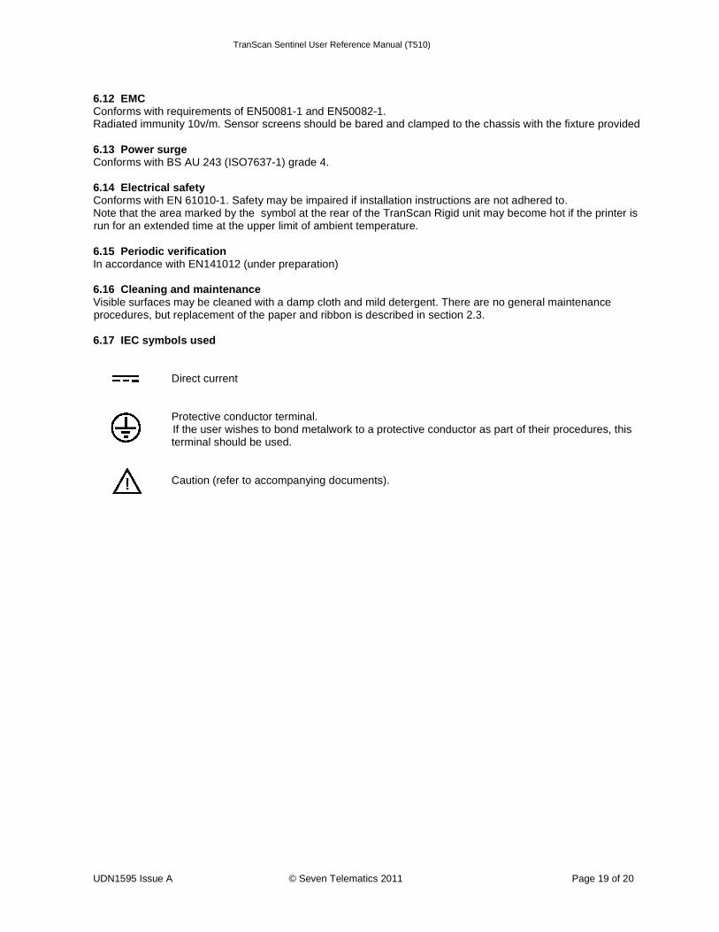
6.12 EMC Conforms with requirements of EN50081-1 and EN50082-1. Radiated immunity 10v/m. Sensor screens should be bared and clamped to the chassis with the fixture provided 6.13 Power surge Conforms with BS AU 243 (ISO7637-1) grade 4. 6.14 Electrical safety Conforms with EN 61010-1. Safety may be impaired if installation instructions are not adhered to. Note that the area marked by the symbol at the rear of the TranScan Rigid unit may become hot if the printer is run for an extended time at the upper limit of ambient temperature. 6.15 Periodic verification In accordance with EN141012 (under preparation) 6.16 Cleaning and maintenance Visible surfaces may be cleaned with a damp cloth and mild detergent. There are no general maintenance procedures, but replacement of the paper and ribbon is described in section 2.3. 6.17 IEC symbols used Direct current Protective conductor terminal.
If the user wishes to bond metalwork to a protective conductor as part of their procedures, this terminal should be used.
Caution (refer to accompanying documents).
TranScan Sentinel User Reference Manual (T510)
UDN1595 Issue A © Seven Telematics 2011 Page 20 of 20
7.0 Declaration of Conformance
Declaration of Conformity to European Council Directives Cold Chain Instruments hereby declare that representative samples of the following products: Models Transcan Trailer (4, 2 ADR, Sentinel) Transcan Rigid (4, 2 ADR, Sentinel) Manufactured by Cold Chain Instruments Ltd 291 Tarring Road Worthing West Sussex UK BN11 5JG have been tested and found to comply with the essential requirements of the following European Council Directives: Electromagnetic Compatibility 89/336/EEC (amended by 93/68/EEC) Quick Frozen Foodstuffs 92/1/EEC (amended by 93/43/EEC) Low Voltage Directive 73/23/EEC Automotive EMC Directive 95/54/EC by application of the following harmonised European Standards: Temperature Recorders EN12830:1999 Generic Emission Standard EN50081-1:1992 Generic Immunity Standard EN50082-1:1997 Environmental Testing (Vibration and Shock) EN60068:1993 Degrees of Protection provided by Enclosures EN60529:1992 Safety of Electrical Equipment EN61010-1:1993/A1:1995 provided that: a. The product is correctly installed in accordance with the installation instructions supplied. b. The product has not been modified in any way. c. The product bears the CE mark. An authorised copy of this declaration is retained at Cold Chain Instruments Ltd