Embed Size (px)
Citation preview

Transceiver
Performance and how
do we measure it?
Rob Sherwood
NCØB
What’s important when it comes to choosing a radio?
Sherwood Engineering

Why Did I Start Testing Radios ?
• Purchased a new Drake R-4C in the 1970s.
• Used it during the ARRL 160m CW contest
• Radio performed miserably, yet Specs Were Good
• 1970s: QST and ham radio magazine introduced new
terminology: Noise Floor & Dynamic Range.
• R-4C tested well for Dynamic Range, but flunked CW
contest 101.
• The ARRL dynamic range test did not approximate a real-
world environment, especially in a CW contest.

• Dynamic Range - measures the ability to hear weak signals in the present of near-by strong signals.
• A 20 kHz Dynamic Range measurement in a multi-conversion radio only tests the radio’s front end.
• If the first IF was 6 - 20 kHz wide, be it at 5 MHz, 9 MHz or 45 - 70 MHz, the radio could overload in a CW pile up.
• 20 kHz dynamic range test showed no hint of the problem
• Solution: Place test signals close together so they pass through 1st IF Filter the Next Amplifier Mixer
• Close-in dynamic range numbers are almost ALWAYS worse than the wide-spaced numbers, for a radio with a single wide roofing filter. (Hilberling the exception)

What 2 Numbers are Most Important
for a CW Contester or DX Pile-up?
• Close-in Dynamic Range (DR3)
• Noise floor
(Noise floor need to calculate DR3)

What is Noise Floor?
Sensitivity is a familiar number, normally applies to SSB.
Sensitivity = 10 dB Signal + Noise / Noise (10 dB S+N/N)
Noise Floor = 3 dB Signal + Noise / Noise (3 dB S+N/N)
Noise floor can be measured at any filter bandwidth, CW or
SSB, for example, and is bandwidth dependent.
League normally only publishes noise floor for a CW
bandwidth, typically 500 Hz CW filter.

Third Order IMD
Signal Signal
IMD IMD
X kHz spacing
X kHz spacing X kHz spacing

What is Dynamic Range?
The range in dB of very strong signals to very weak signals
that the receiver can handle At The Same Time
What is Close-in Dynamic Range vs
Wide-Spaced Dynamic Range?
Why is Close-in Dynamic so important for CW ops?
Why is it less important for SSB operators?

Wide & Close Dynamic Range
20 kHz Spacing 2 kHz Spacing
First IF Filter at 70.455 MHz
IMD 20 kHz Away
15 kHz Wide
First IF Filter at 70.455 MHz
IMD 2 kHz Away
15 kHz Wide

This keeps the undesired strong signals from progressing
down stream to the next stages
Filter
500 Hz
Wide
Filter
6–15 kHz
Wide Amplifier Mixer Mixer
Filter
600 Hz
Wide
What if we could switch in a narrow Roofing Filter only
slightly wider than the final selectivity?

What are roofing filter limits?
Fractional bandwidth of the filter is a big issue.
It is easy to make a 500-Hz filter at 9 MHz, but not at 70 MHz
Passive IMD in the roofing filter itself is often the limit for radios with a
true dynamic range (DR3) of 90 dB or greater.
I have observed passive IMD in Ten-Tec, Kenwood and Elecraft roofing
filters.
With the K3, for example, you can spend up to $700 for roofing filters for
the main receiver, and an additional $700 for the sub receiver !
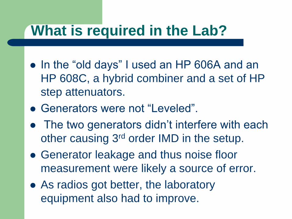
What is required in the Lab?
In the “old days” I used an HP 606A and an
HP 608C, a hybrid combiner and a set of HP
step attenuators.
Generators were not “Leveled”.
The two generators didn’t interfere with each
other causing 3rd order IMD in the setup.
Generator leakage and thus noise floor
measurement were likely a source of error.
As radios got better, the laboratory
equipment also had to improve.

Progression of Sig Gens over time
606A & 608C, low noise, no leveling problem
but leakage issues at sub-microvolt levels.
8640Bs, low phase noise, leveling problem
but lower leakage for noise floor test.
8662As, lower close-in phase noise, leveling
issue and excellent low leakage.
8642As, even lower phase noise, leveling
issue, and excellent low leakage.

The lab setup requires high isolation
Gen
Gen
Gen
Buf
Buf
Buf
LPF
LPF
LPF
20 dB
Pad
20 dB
Pad
20 dB
Pad
Hybrid Variable
Atten
10 dB
Pad
Radio
Leveled generators cause problems !

ARRL Dynamic Range Numbers
Many modern transceivers are phase noise
limited, particularly close-in at 2 kHz. The
League wanted to be able subtract out the
phase noise when measuring IMD, and came
up with a new method in 2007 using a
spectrum analyzer with a 3-Hz filter using an
audio spectrum analyzer.
Later used a 1-Hz or narrower filter with an
FFT analyzer make measurements quicker.

HP 3561A FFT Analyzer

IC-7600 with 3-Hz Spectrum Analyzer
Phase noise
limited
dynamic
range is 78
dB at 2 kHz.
Measured
with a 3-Hz
filter on the
analyzer, the
dynamic
range is 87
dB at 2 kHz!
IMD @ -130 dBm Reference tone
-130 dBm
500 Hz DSP
Filter Passband

ARRL 2007 – 2011 DR3 Method
2006 and earlier, IMD or noise increased 3
dB. This was published as the dynamic
range, either IMD or noise limited.
With the 2007 - 2011 method, phase noise
buried the IMD product.
3-Hz filter used for the third-order dynamic
range measurement, and the published
values were greater than in 2006 and before.
Non synthesized rigs (S-Line / C-Line) would
not have any reciprocal-mixing issues.

IC-7410 Dynamic Range Data
Spacing Value
100 kHz 107 dB some noise
20 kHz 102 dB noise limited
5 kHz 90 dB noise limited
2 kHz 78 dB noise limited
2 kHz ARRL* 89 dB noise ignored
* (Using spectrum analyzer and narrow BW)
Example

The ARRL / Sherwood Compromise
In September 2011 the League agreed to add
emphasis to their reciprocal-mixing data. The first
Product review with the testing change was April 2012.
The League’s reciprocal-mixing (RMDR) values should
equal their pre-2007 noise-limited data, and my
published noise-limited or IMD limited data.
IC-7410 RMDR limited dynamic range = 78 dB
Sherwood noise-limited DR3 = 78 dB
The IC-9100 review uses the new reporting, and has a
nice sidebar on page 55 explaining the changes.

Phase Noise Revisited in IC-9100 review
The League’s third-order dynamic range is
measured in such a way to eliminate phase
noise from the equation. Their new 2-kHz
reciprocal-mixing dynamic range can be
equated to 2006 and older “phase noise
limited” dynamic range data.
Icom IC-9100 data, April QST 2012
2-kHz 3rd order DR3 = 87 dB (with 1-Hz filter)
2-kHz reciprocal mixing dynamic range 77 dB

Now both RMDR and 1-Hz Data is Presented
Currently ARRL blocking and DR3 use a 1-Hz
filter to remove phase noise.
For most radios RMDR is the limit.
If DR3 is 100 dB, but RMDR is 80 dB the
smaller value is the performance limit.
The 1-Hz data is useful to the design engineer.
RMDR data is more useful to the ham operator.
You choose which data to consider
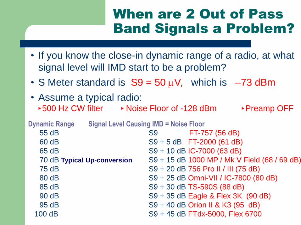
When are 2 Out of Pass
Band Signals a Problem?
• If you know the close-in dynamic range of a radio, at what
signal level will IMD start to be a problem?
• S Meter standard is S9 = 50 V, which is –73 dBm
• Assume a typical radio: 500 Hz CW filter Noise Floor of -128 dBm Preamp OFF
Dynamic Range Signal Level Causing IMD = Noise Floor
55 dB S9 FT-757 (56 dB)
60 dB S9 + 5 dB FT-2000 (61 dB)
65 dB S9 + 10 dB IC-7000 (63 dB)
70 dB Typical Up-conversion S9 + 15 dB 1000 MP / Mk V Field (68 / 69 dB)
75 dB S9 + 20 dB 756 Pro II / III (75 dB)
80 dB S9 + 25 dB Omni-VII / IC-7800 (80 dB)
85 dB S9 + 30 dB TS-590S (88 dB)
90 dB S9 + 35 dB Eagle & Flex 3K (90 dB)
95 dB S9 + 40 dB Orion II & K3 (95 dB)
100 dB S9 + 45 dB FTdx-5000, Flex 6700

The DR3 “window” is not fixed
The dynamic range of a radio is the same with an
attenuator ON or OFF.
If on a noisy band, attenuate the noise and all signals to
make better use of the dynamic range, and reduce the
chance of overload.
If band noise goes from S6 to S2 by turning on the
attenuator, you have lost nothing, yet your radio is being
stressed much less.

A Comment on IP3 (3rd Order Intercept)
I don’t publish IP3. It is a theoretical number.
It has more meaning for a block amplifier or mixer.
Almost meaningless if the AGC of a receiver is involved
October 2007 QST Product Review FT-2000D
DR3 Spacing Level IP3
98 dB 20 kHz Noise Floor +25 dBm
69 dB 2 kHz Noise Floor -19 dBm
29 dB 2 kHz 0 dBm = S9+73 dB +15 dBm

Attenuators, Preamps & IP3
Dynamic range is constant if you enable an attenuator
and often constant even with preamp enabled. IP3 varies
all over the map. Data from March QST 2008 FT-950
Gain Dynamic Range IP3 dBm
Pre 2 95 +4 (published)
Pre 1 95 +13 (published)
No Preamp 94 +22 (published)
Att 6 dB 94 +28 (calculated)
Att 12 dB 94 +34 (calculated)
Att 18 dB 94 +40 (calculated)

Comments on Blocking & Phase Noise
Blocking is the onset of gain compression.
This can be an issue with another ham within “line-of-site”.
It is an issue on Field Day and multi-multi contest stations.
Low phase noise is desirable, but a very good low phase-
noise receiver has to contend with transmitted phase
noise.
Dealing with transmitted phase noise is like dealing with
transmitted IMD products and splatter.
We cannot do much about it.

Blocking & 1 Hz FFT measurements
The ARRL measures blocking since 2007 in a 1 Hz bandwidth.
With most radios, if we measure blocking in a 500-Hz bandwidth,
the signal at the speaker goes UP, not DOWN !
In other words, the phase noise (reciprocal mixing) dominates
over gain compression.
Just like DR3 numbers being higher with a 1-Hz measurement,
the blocking numbers are exaggerated when measured at audio
with an FFT spectrum analyzer.
The bottom line: Understand what the numbers really mean.

Lets now move from CW to SSB
Why are the dynamic range requirements less
stringent on SSB than on CW?
On CW the limitation on working weak signals very
close to a strong signal is often the keying
sidebands of the QRM, once the dynamic range is
good enough. (Discussed later)
On SSB the limitation is often the distortion
products from an adjacent station a few kHz up or
down the band.

Transmitted IMD Collins 32S-3
Third order down -36 dB

Icom 781 on 20 meters @ 150 Watts
-34 dB 3rd order, -43 dB 7th order

Icom 756 Pro III on 20 meters @ 70 W
-27 dB 3rd order, 40 dB 7th order

Third order IMD down only -27 dB
Elecraft K3 on 20 meters
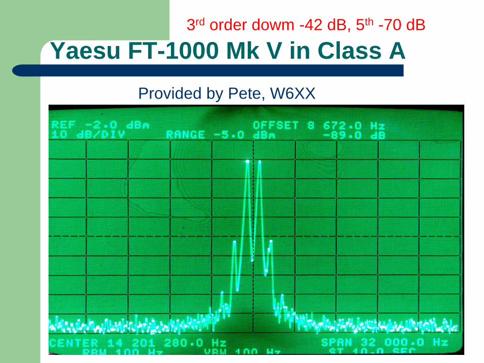
Yaesu FT-1000 Mk V in Class A
Provided by Pete, W6XX
3rd order dowm -42 dB, 5th -70 dB

Mk V Class A + 8877 Linear Amplifier
3rd order only 2 dB worse @ -40 dB

Compare the Old vs. New Order Collins Yaesu Difference
IMD 32S-3 FT-450 in dB
QST
3rd -42 dB -30 dB 12 dB
5th -53 dB -37 dB 16 dB
7th -66 dB -42 dB 24 dB (Note)
9th -77 dB -48 dB 29 dB
Have to add 6 dB to compare to PEP method

Close-in Signal and Splatter
IF Filter vs. Adjacent Signal and IMD Splatter
Signal 5 kHz Away
-60 dB, 7th Order

Steady-State vs. Dynamic Splatter
Some transceivers, in addition to normal IMD products, produce additional ALC-Induced splatter. On CW the ALC can cause leading-edge key clicks.
ALCs could be driven hard in a 32S-3 or a T-4XC, for example, and not add to splatter.
Some modern rigs splatter more if the ALC is more than “tickled”, or induce clicks on CW.
The League has chosen not to address this problem in its equipment reviews. SM5BSZ & I tried to no avail.

How Many Roofing Filters are Needed?
It depends on your mode of operation.
For SSB, a single 15 kHz roofing filter is adequate, such as in the Icom 756 Pro II / Pro III with a close-in dynamic range of 75 dB.
Other radios with similar performance: Drake R7 and TR7, IC-781, Collins 75S-3B/C, TS-930, FT-1000x, T-T Omni-V or VI.
Would a 2.7 kHz roofing filter be better?
Yes, K3, Orion, Omni-VII
On CW, a single wide roofing filter is not optimum.
CW signals do not have IMD products. Strong adjacent signals do not have as much energy in the CW passband of your filter.
A CW Signal Does have a Bandwidth. It is NOT zero bandwidth

Roofing Filter BW on SSB
Do you need more than one SSB BW Filter?
Best if Roofing & DSP bandwidths are equal.
More selectivity up front is always desirable.
Better shape factor than depending of last IF only.
Omni-VII the 455 kHz filters really help total selectivity.
Orion & K3 both offer a 1.8 kHz roofing filter.
Reduces load on DSP !
Just not as dramatic improvement as on CW.

Back to CW signals
We have seen how width of an SSB signal & its
IMD products affects how close you can operate
to another station.
How does CW compare?
How close can we work to a strong adjacent CW
signal?
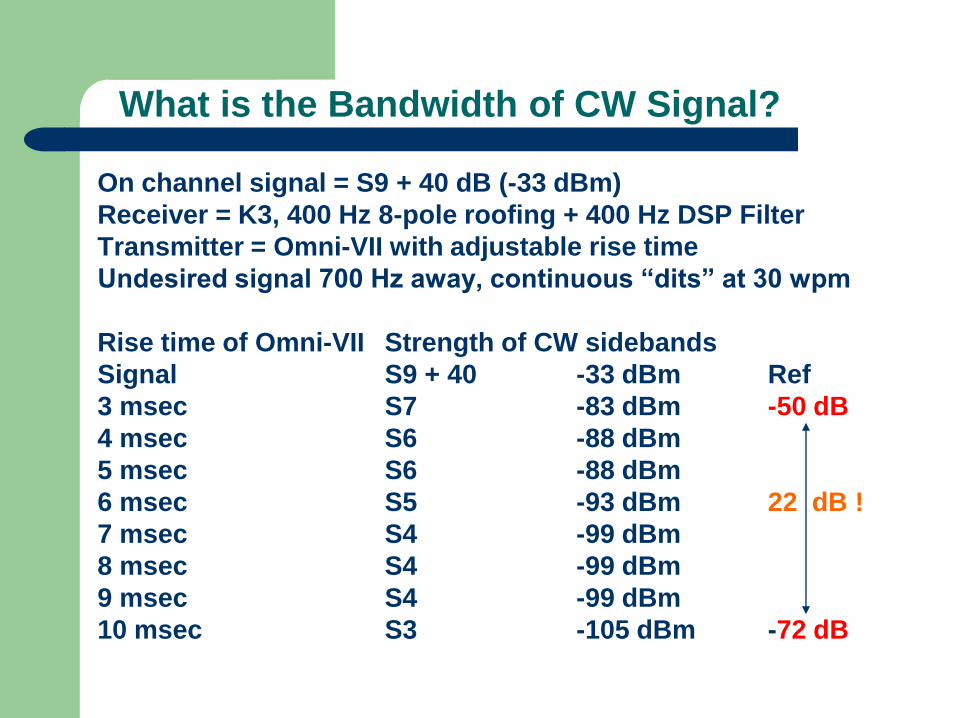
What is the Bandwidth of CW Signal?
On channel signal = S9 + 40 dB (-33 dBm)
Receiver = K3, 400 Hz 8-pole roofing + 400 Hz DSP Filter
Transmitter = Omni-VII with adjustable rise time
Undesired signal 700 Hz away, continuous “dits” at 30 wpm
Rise time of Omni-VII Strength of CW sidebands
Signal S9 + 40 -33 dBm Ref
3 msec S7 -83 dBm -50 dB
4 msec S6 -88 dBm
5 msec S6 -88 dBm
6 msec S5 -93 dBm 22 dB !
7 msec S4 -99 dBm
8 msec S4 -99 dBm
9 msec S4 -99 dBm
10 msec S3 -105 dBm -72 dB
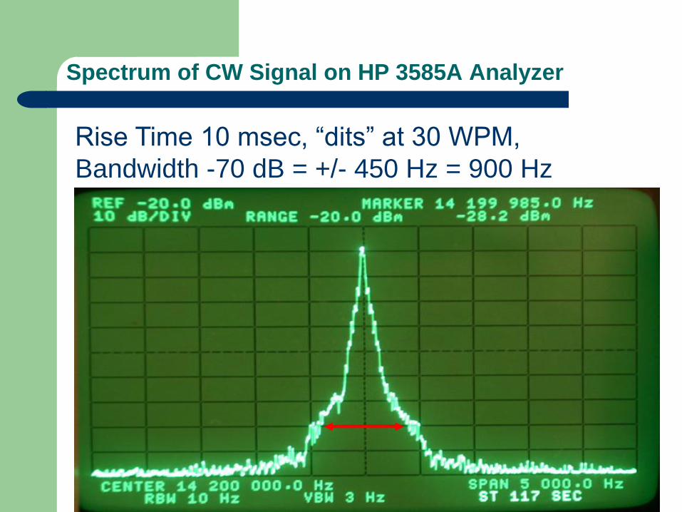
Spectrum of CW Signal on HP 3585A Analyzer
Rise Time 10 msec, “dits” at 30 WPM,
Bandwidth -70 dB = +/- 450 Hz = 900 Hz

Spectrum of CW Signal on HP 3585A Analyzer
Rise Time 3 msec, “dits” at 30 WPM,
Bandwidth -70 dB = +/- 750 Hz = 1500 Hz

Spectrum of CW Signal on HP 3585A Analyzer
Comparison of 3 msec vs 10 msec rise time
20 dB
difference

Leading edge of “dit” 3 & 10 msec
How Many Poles Are Needed for a narrow CW roofing filter? Orion II 600 Hz 4-pole filter is - 30 dB @ +/-700 Hz
Orion II 600 Hz 4-pole filter is – 50 dB @ +/-1200 Hz
A signal 2-kHz away is in the stop band of any filter.
Typical CW signal is +/- 700 Hz wide at –70 dB
The Orion II uses 4-pole roofing filters.
Sherwood has used a 6-pole filter for 32 years.
Elecraft uses both 5 and 8-pole filters.
I see no significant advantage of one choice over another.

From a Dynamic Range standpoint, reducing a strong adjacent signal 30 dB with a roofing filter is adequate. All the roofing filters from Elecraft, Kenwood, Ten-Tec or Yaesu do the job. More poles have more insertion loss and cost more. Its a trade-off. Compared to a 15 kHz roofing filter, a 500 Hz CW roofing filters will pass about 3% of those signals on to the later stages of the radio. You likely cannot work a weak signal 500 Hz from an S9 +40 dB CW signal with any radio with the best roofing filter due to the transmitted bandwidth (keying sidebands) of the interfering signal.
Just the facts

Conclusions
Contesters – DXers – Pileup operators need a good receiver for SSB and an even better receiver for CW.
The Sherwood 600-Hz CW roofing filter fixed the R-4C in 1976.
Ten-Tec Orion put that concept in a commercial design in 2003.
Elecraft K3 offered multiple roofing filters in 2008.
Now Kenwood & Yaesu have followed suit.

25 years of up conversion radios have generally
offered a 20 kHz dynamic range in the 90s but a 2 kHz
close-in dynamic range in the 70s. Typical degradation of
dynamic range within the up conversion filter bandwidth
is 25 dB.
Some brands offer a 3-kHz roofing filter in up-
conversion radios, though filter is often wider than spec.
IC-7800 3-kHz filter is 5+ kHz wide, 6-kHz is 11+ kHz
FT-2000 3-kHz filter is 7 kHz wide, and with my
sample, it had 9 dB worse IMD than its 6 kHz filter.

It is not possible to offer CW bandwidth
Roofing Filters at VHF frequencies.
It all comes down to fractional bandwidth.
A 500-Hz filter at 5 MHz is like a 1-kHz filter at
10 MHz, or a 2 kHz filter at 20 MHz or a 4 kHz
filter at 40 MHz & an 8 kHz filter at 80 MHz.
FTdx-9000 IF = 40 MHz, 3-kHz reasonable.
FT-2000 IF = 70 MHz, “3 kHz” = 7 kHz wide
The Orion II and the K3 roofing filters are in
the 8 to 9 MHz range, similar to the R-4C at 5
MHz. Narrow filters are no problem here.
How Narrow Can a VHF Filter Be?

Flex Radio and Apache ANAN
Flex and Apache have are now using a direct sampling architecture.
There are no mixers or roofing filters.
The number crunching can be done in the computer (Apache) or in an
FPGA in the radio (Flex).
While the hardware costs money, the real cost of development is in the
software.
I have used both the Flex 6700 and ANAN-200D in recent CW contests.
Both perform very well, with limitations in respect to logging.
We can discuss this later if there is interest.

80 dB or better @ 2 kHz.
1976 Sherwood / Drake R-4C: 84 dB
2001 Ten-Tec Omni-VI+: 80 dB
2003 Icom IC-7800: 80 dB
2003 Ten-Tec Orion I: 93 dB
2005 Ten-Tec Orion II: 95 dB
2007 Flex 5000A: 96 dB
2008 Elecraft K3: 95 dB
2010 to date: Yaesu, Hilberling, Flex: 100 dB
What dynamic range is possible and needed for CW?

Elecraft K2: 80 dB
Collins R-390A: 79 dB
Kenwood TS-850S: 77 dB
Icom Pro II / Pro III 75 dB
Collins 75S-3B/C: 72 dB
Kenwood TS-870S: 69 dB
Yaesu FT-2000: 63 dB
Icom IC-7000: 63 dB
Yaesu FT-One: 63 dB
Yaesu FT-101E: 59 dB
Drake R-4C Stock: 58 dB
Yaesu FT-757: 56 dB
Yaesu VR-5000: 49 dB
Other radios for comparison, 2 kHz dynamic range data

Contest Fatigue & Audio Quality - The Forgotten Spec
Two transceivers made me tired in a long contest.
The audio was harsh on SSB and CW. Met OEM Spec
OEM spec = 2.5 watts @ 10% distortion = clipping
What makes audio harsh and fatiguing?
High Odd-Order Harmonics and / or IM Distortion
The ear / brain is very sensitive to these products.
Any product detector & audio amp will meet 10% spec
Thus the spec is meaningless.
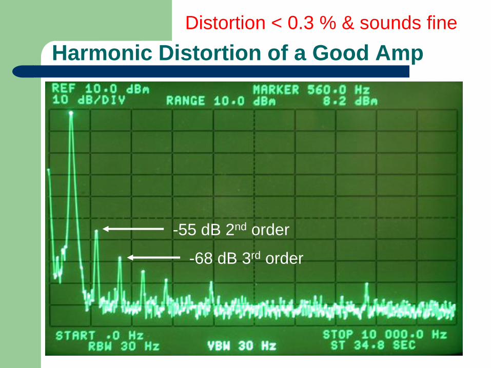
Harmonic Distortion of a Good Amp
Distortion < 0.3 % & sounds fine
-55 dB 2nd order
-68 dB 3rd order

IM distortion of Good Amp
Distortion = 0.3 % & sounds fine
-53 dB 3rd order

Not So Good Amp & Odd Order > Even
Distortion < 0.3 % but sounds bad
-65 dB 11th order

Way too much IM Distortion
3% distortion but sounds terrible !
-40 dB 9th order IMD

Screen shot from Elecraft Lab Fall 2008
Factory Confirms K3 Audio Problem
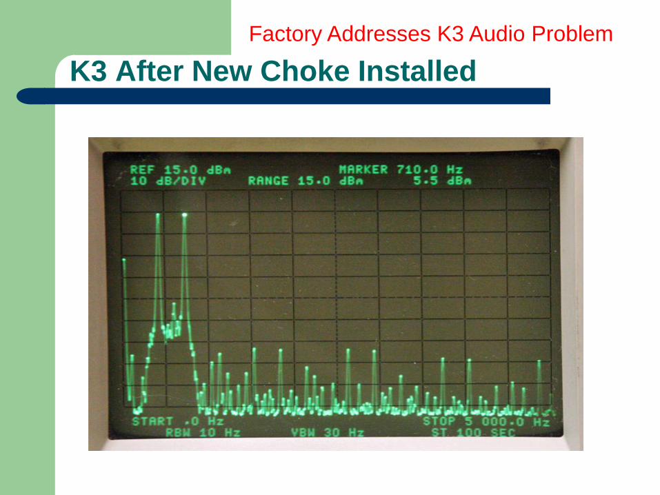
K3 After New Choke Installed
Factory Addresses K3 Audio Problem

Icom 756 Pro III Harmonic Distortion
0.1 % distortion

Icom 756 Pro III in-band IMD Distortion
< 0.3 % distortion
-54 dB 3rd Order IMD

Considerations in Choosing a Transceiver
High close-in dynamic range (copy S1 in crowded band)
Low noise floor (copy very weak signals)
Low phase noise (low noise on the Local Oscillator)
Low in-band spurious on both receive and transmit
Low IMD on SSB transmit, and low key clicks on CW transmit
Effective SSB speech processor (more talk power)
Good receive and transmit audio quality (intelligibility)
Smooth AGC for low fatigue (noise doesn’t fill in spaces)
AGC that doesn’t exaggerate impulse noise (hangs up AGC)
Good ergonomics of controls and menus (easy adjustments)
Good display that also shows important settings
The Challenge = Get OEMs to Listen
In a 24 hour or 48 hour contest, you need every edge.
High Dynamic Range Receiver
Good Speech Processor on SSB
Big Tower and Good Antennas, etc.
But Your Brain Can Get “Fried” due to operator fatigue.
Bad audio can be a factor in that fatigue.

Sherwood Engineering
http://www.sherwood-engineering.com
http://www.NC0B.com