Embed Size (px)
DESCRIPTION
tài liệu mạng
Citation preview
CS646: Software Design and Architectures
Design methods: SSA/SD†
Stands for: Structured Systems Analysis / Structured Design.Primary applicable notations:
DFDsStructure Charts
Secondary notations:ERDsPseudo-codeData Dictionary
Overall objective: Derive “white box” structure chart.________________† Material from text by Budgen and from “Software Engineering: A Practitioner’s Approach (4th edition)”, by Roger Pressman.
CS646: Software Design and Architectures
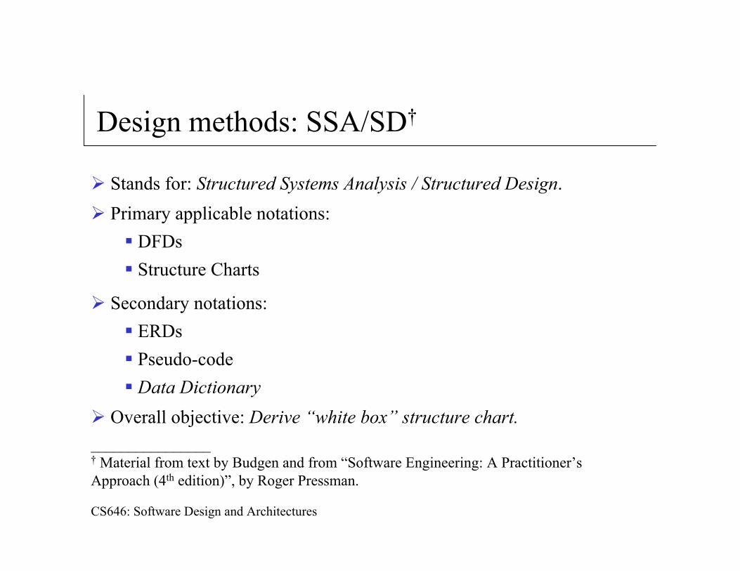
Effective modular design
Module: a grouping of related routines or data.
Diagrammatic convention: ModuleReferenceModuleName
Modularization criteria:
coupling: The degree of interconnection between modules.
cohesion: The strength of relationship between elements of a particular module; the “single mindedness of purpose” of the module.
CS646: Software Design and Architectures
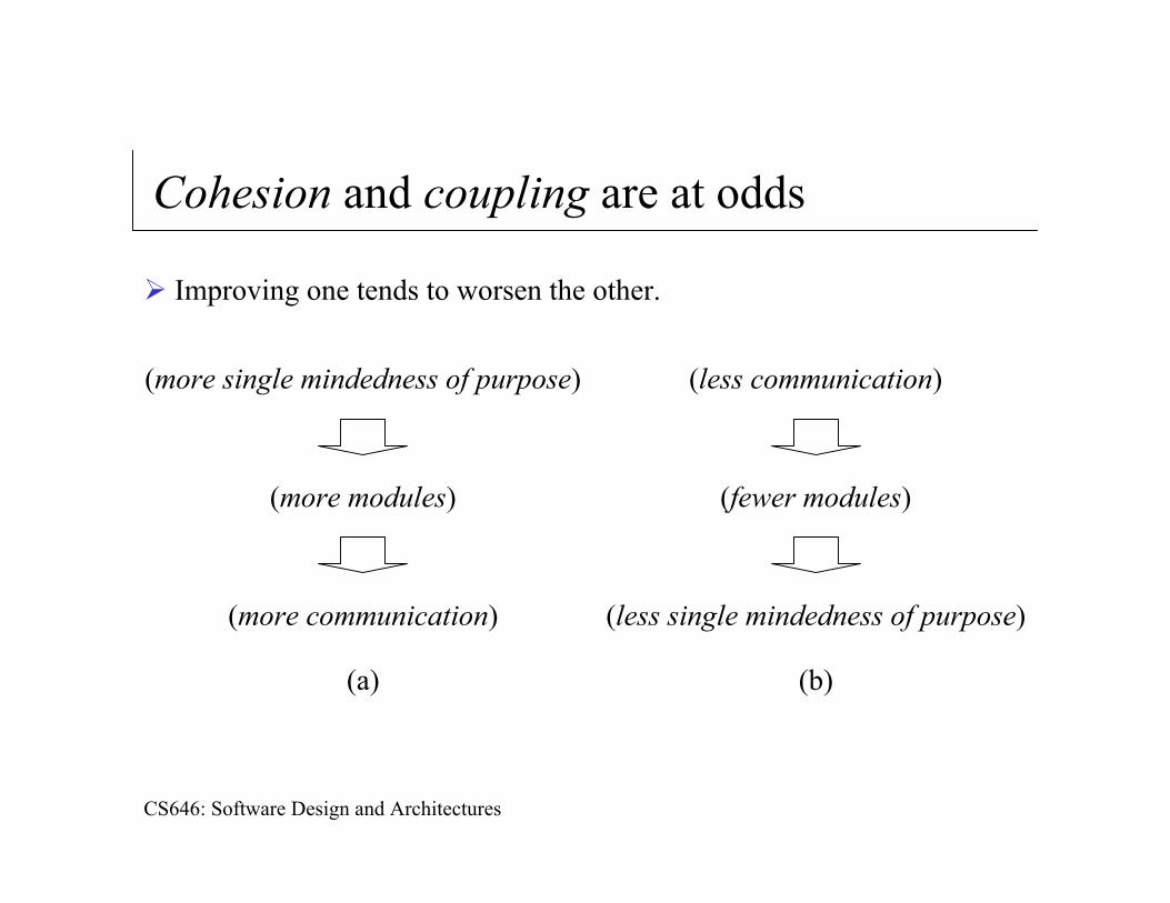
Cohesion and coupling are at odds
Improving one tends to worsen the other.
(more single mindedness of purpose)
(more modules)
(more communication)
(a)
(less communication)
(fewer modules)
(less single mindedness of purpose)
(b)
CS646: Software Design and Architectures
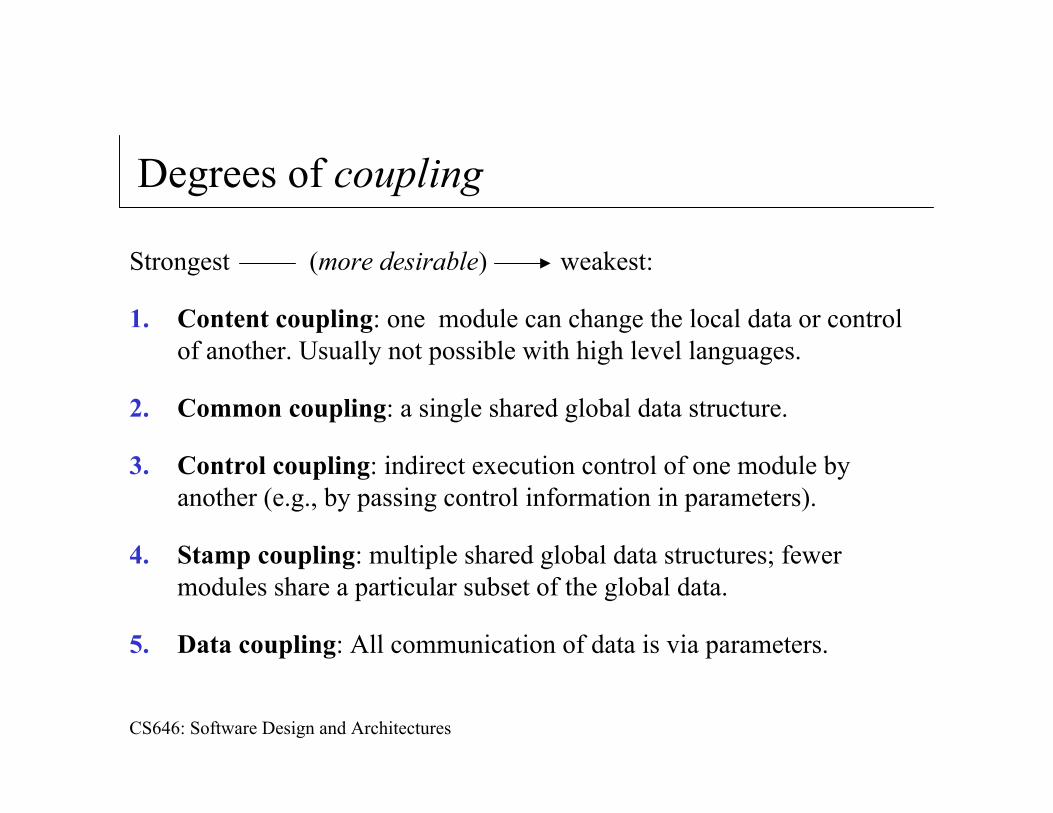
Degrees of coupling
Strongest (more desirable) weakest:
1. Content coupling: one module can change the local data or control of another. Usually not possible with high level languages.
2. Common coupling: a single shared global data structure.
3. Control coupling: indirect execution control of one module by another (e.g., by passing control information in parameters).
4. Stamp coupling: multiple shared global data structures; fewer modules share a particular subset of the global data.
5. Data coupling: All communication of data is via parameters.
CS646: Software Design and Architectures
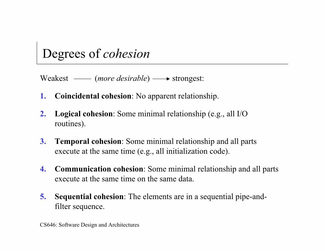
Degrees of cohesion
Weakest (more desirable) strongest:
1. Coincidental cohesion: No apparent relationship.
2. Logical cohesion: Some minimal relationship (e.g., all I/O routines).
3. Temporal cohesion: Some minimal relationship and all parts execute at the same time (e.g., all initialization code).
4. Communication cohesion: Some minimal relationship and all parts execute at the same time on the same data.
5. Sequential cohesion: The elements are in a sequential pipe-and-filter sequence.
CS646: Software Design and Architectures
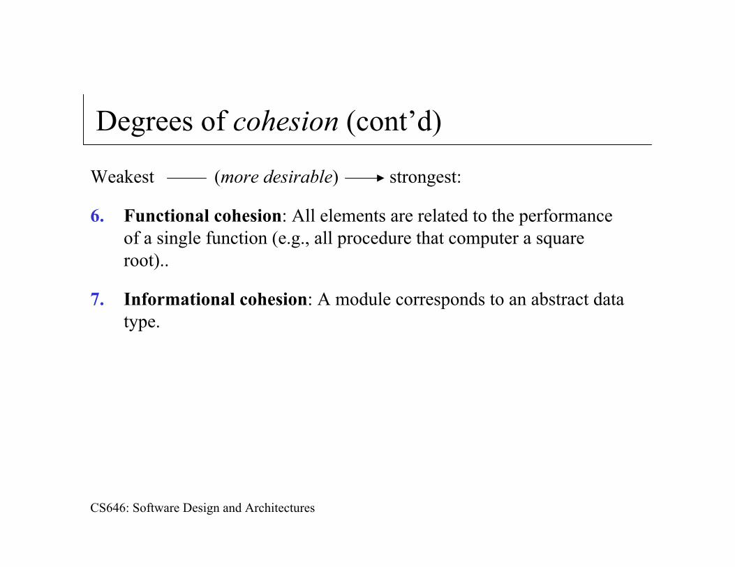
Degrees of cohesion (cont’d)
Weakest (more desirable) strongest:
6. Functional cohesion: All elements are related to the performance of a single function (e.g., all procedure that computer a squareroot)..
7. Informational cohesion: A module corresponds to an abstract data type.
CS646: Software Design and Architectures
SSA/SD Process (from text and Pressman)
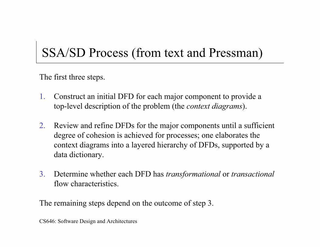
The first three steps.
1. Construct an initial DFD for each major component to provide a top-level description of the problem (the context diagrams).
2. Review and refine DFDs for the major components until a sufficient degree of cohesion is achieved for processes; one elaborates thecontext diagrams into a layered hierarchy of DFDs, supported by a data dictionary.
3. Determine whether each DFD has transformational or transactionalflow characteristics.
The remaining steps depend on the outcome of step 3.
CS646: Software Design and Architectures
Flow types
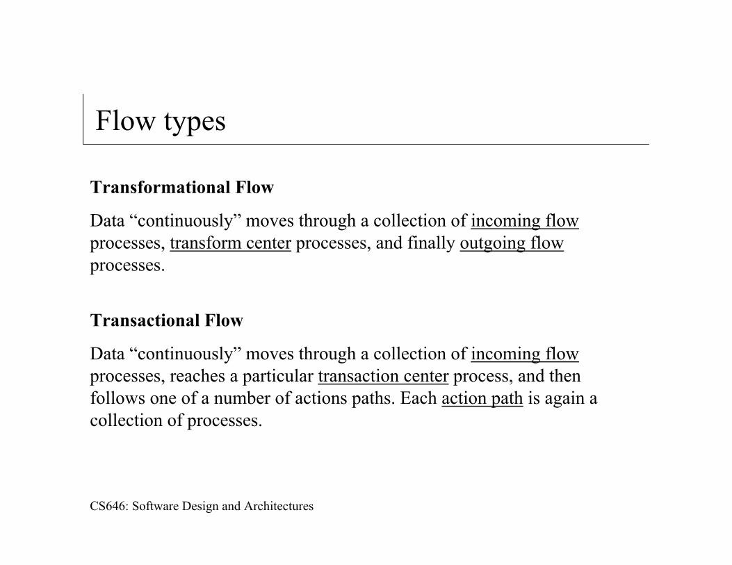
Transformational Flow
Data “continuously” moves through a collection of incoming flowprocesses, transform center processes, and finally outgoing flowprocesses.
Transactional Flow
Data “continuously” moves through a collection of incoming flowprocesses, reaches a particular transaction center process, and then follows one of a number of actions paths. Each action path is again a collection of processes.
CS646: Software Design and Architectures
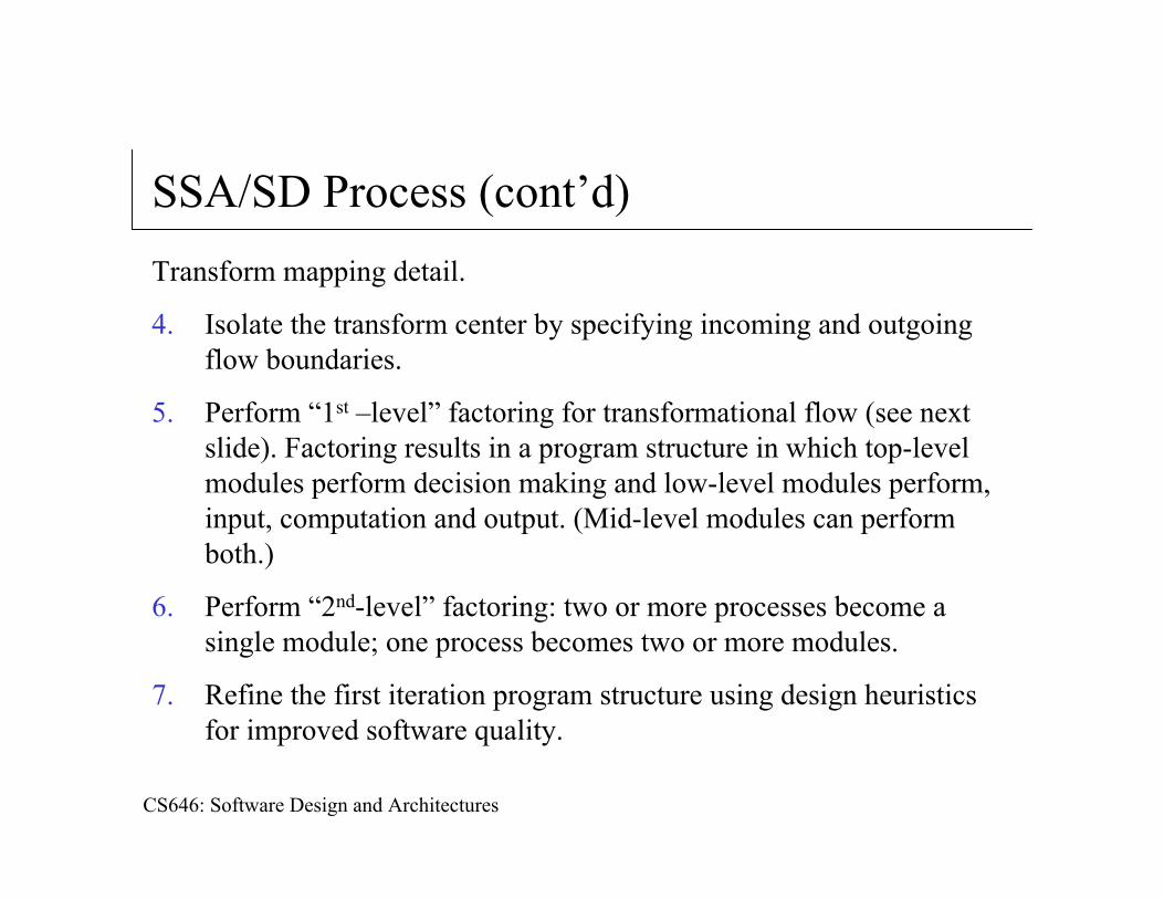
SSA/SD Process (cont’d)Transform mapping detail.
4. Isolate the transform center by specifying incoming and outgoingflow boundaries.
5. Perform “1st –level” factoring for transformational flow (see next slide). Factoring results in a program structure in which top-level modules perform decision making and low-level modules perform, input, computation and output. (Mid-level modules can perform both.)
6. Perform “2nd-level” factoring: two or more processes become a single module; one process becomes two or more modules.
7. Refine the first iteration program structure using design heuristics for improved software quality.
CS646: Software Design and Architectures
SSA/SD Process (cont’d)
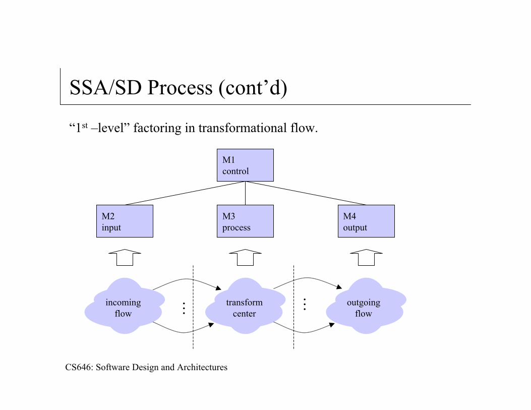
“1st –level” factoring in transformational flow.
......incoming
flowtransform
centeroutgoing
flow
M1control
M4output
M3process
M2input
CS646: Software Design and Architectures
SSA/SD Process (cont’d)
Transaction mapping detail.
4. Identify the transaction center, and the flow characteristics along each of the action paths.
5. Perform “1st –level” factoring for transactional flow (see next slide); map the DFD to a program structure amenable to transaction processing.
6. Factor and refine the transaction structure and the structure of each action path.
7. Refine the first iteration program structure using design heuristics for improved software quality.
CS646: Software Design and Architectures
SSA/SD Process (cont’d)
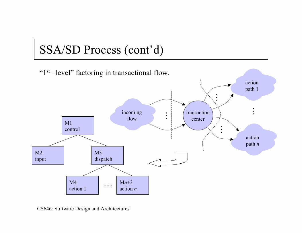
“1st –level” factoring in transactional flow.
...incomingflow
transactioncenter
actionpath 1
actionpath n
...transactioncenter
...
...
M1control
M2input
M3dispatch
Mn+3action n
M4action 1
…
CS646: Software Design and Architectures
Design heuristics for effective modularity
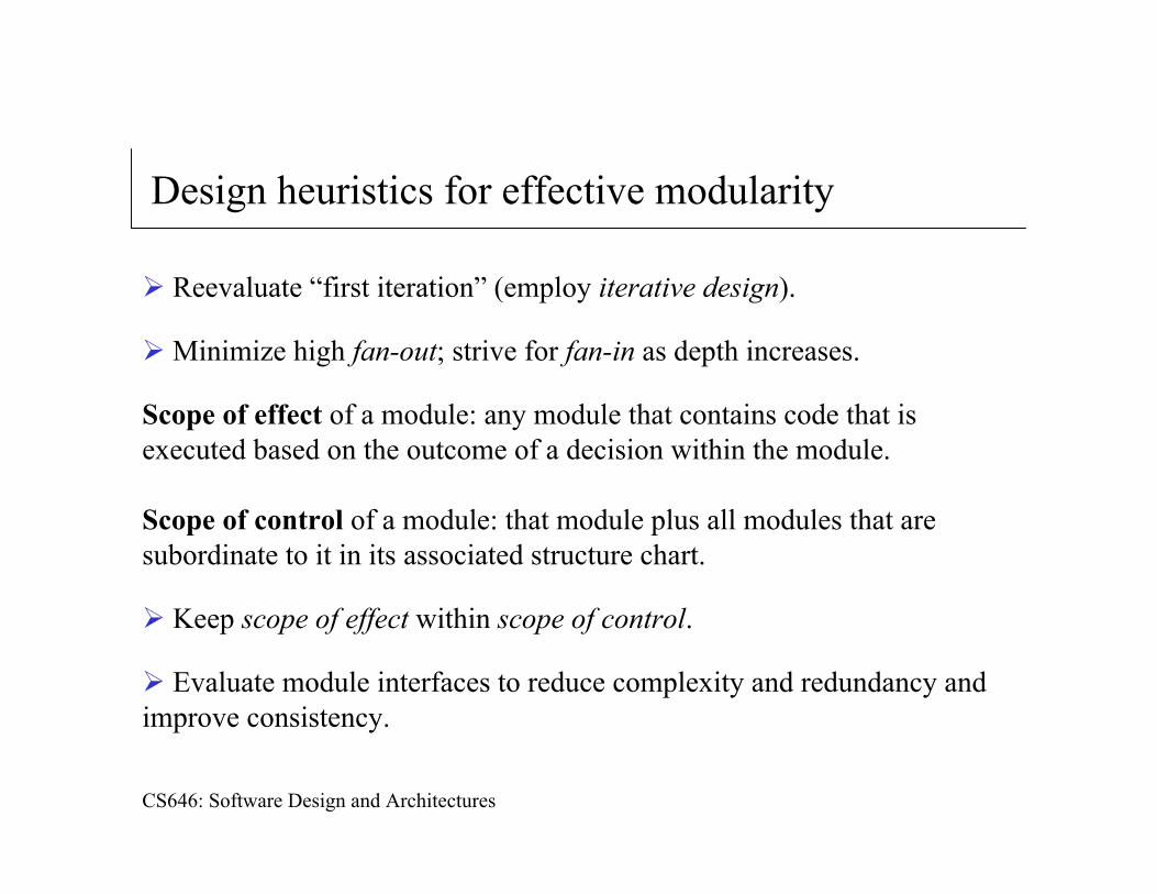
Reevaluate “first iteration” (employ iterative design).
Minimize high fan-out; strive for fan-in as depth increases.
Scope of effect of a module: any module that contains code that is executed based on the outcome of a decision within the module.
Scope of control of a module: that module plus all modules that are subordinate to it in its associated structure chart.
Keep scope of effect within scope of control.
Evaluate module interfaces to reduce complexity and redundancy and improve consistency.
CS646: Software Design and Architectures
Design heuristics for effective modularity (cont’d)
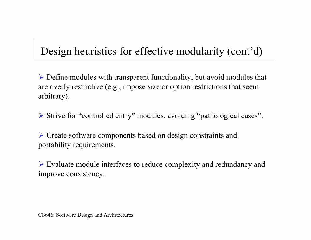
Define modules with transparent functionality, but avoid modules that are overly restrictive (e.g., impose size or option restrictions that seem arbitrary).
Strive for “controlled entry” modules, avoiding “pathological cases”.
Create software components based on design constraints and portability requirements.
Evaluate module interfaces to reduce complexity and redundancy and improve consistency.
CS646: Software Design and Architectures
Design postprocessing
After structure charts have been developed and refined, the following tasks must be completed.
A processing narrative must be developed for each module.
An interface description is provided for each module.
Local and global data structures are refined or designed.
All design restrictions and limitations are noted.
A design review is conducted.
“Optimization” is considered (if required and justified).
CS646: Software Design and Architectures
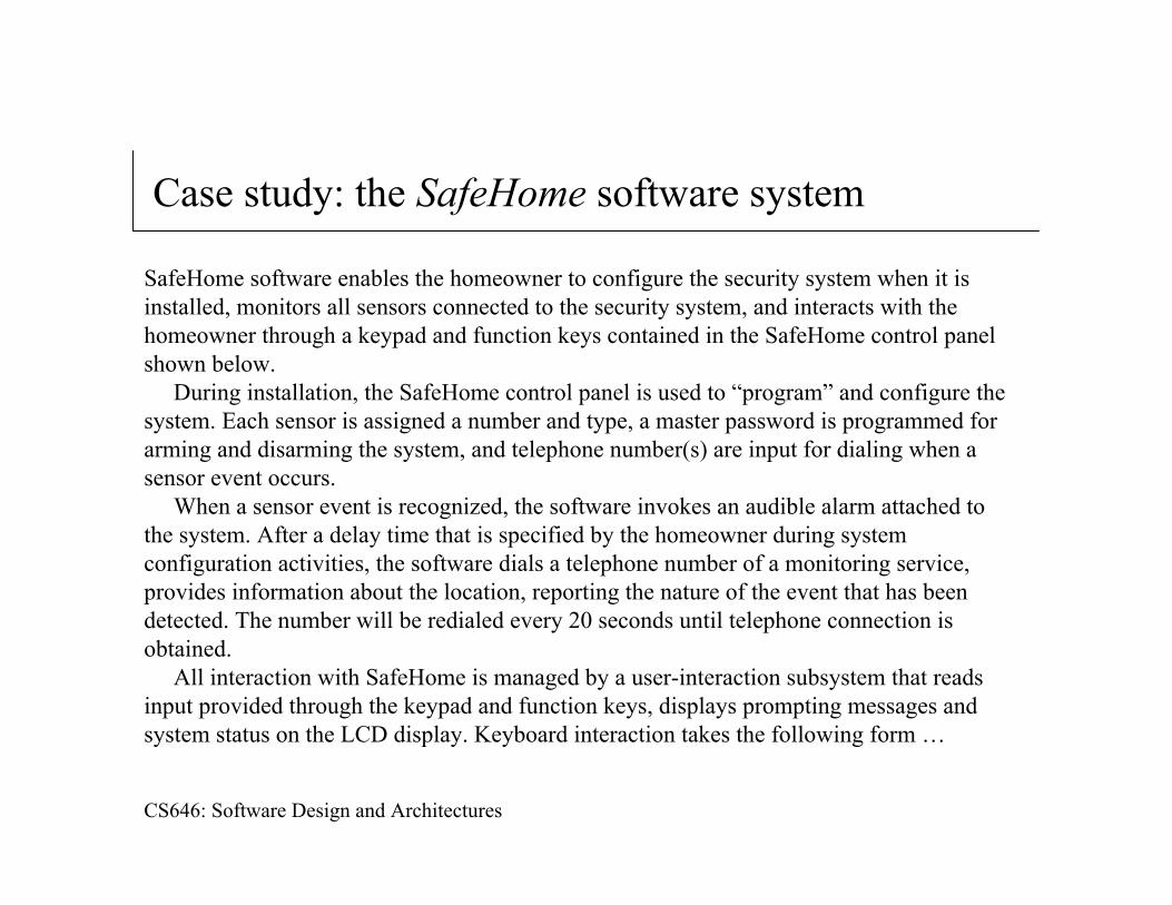
Case study: the SafeHome software system
SafeHome software enables the homeowner to configure the security system when it is installed, monitors all sensors connected to the security system, and interacts with the homeowner through a keypad and function keys contained in the SafeHome control panel shown below.
During installation, the SafeHome control panel is used to “program” and configure the system. Each sensor is assigned a number and type, a master password is programmed for arming and disarming the system, and telephone number(s) are input for dialing when a sensor event occurs.
When a sensor event is recognized, the software invokes an audible alarm attached to the system. After a delay time that is specified by the homeowner during system configuration activities, the software dials a telephone number of a monitoring service, provides information about the location, reporting the nature of the event that has been detected. The number will be redialed every 20 seconds until telephone connection is obtained.
All interaction with SafeHome is managed by a user-interaction subsystem that reads input provided through the keypad and function keys, displays prompting messages and system status on the LCD display. Keyboard interaction takes the following form …
CS646: Software Design and Architectures
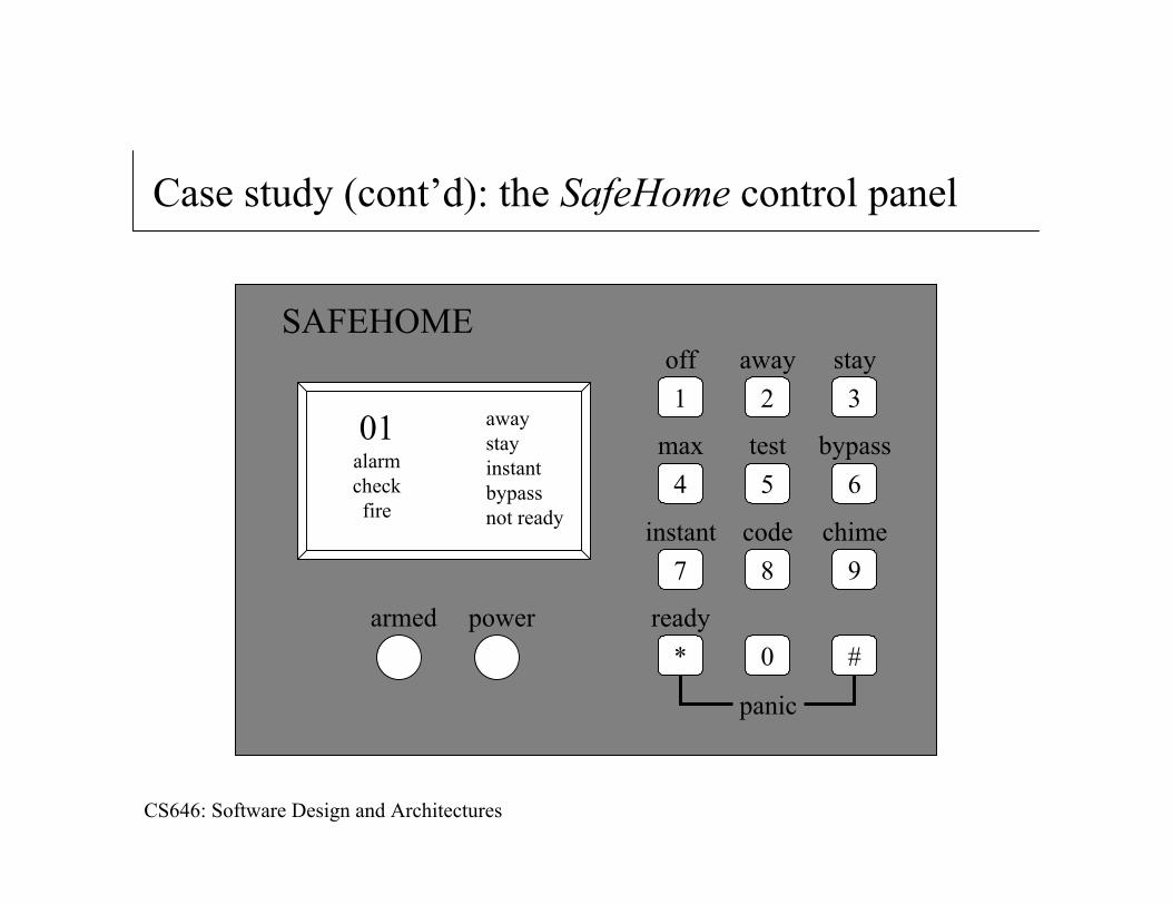
Case study (cont’d): the SafeHome control panel
SAFEHOME
1off
3stay
2away
4max
6bypass
5test
7instant
9chime
8code
*ready
#0
panic
powerarmed
01alarmcheckfire
awaystayinstantbypassnot ready
CS646: Software Design and Architectures
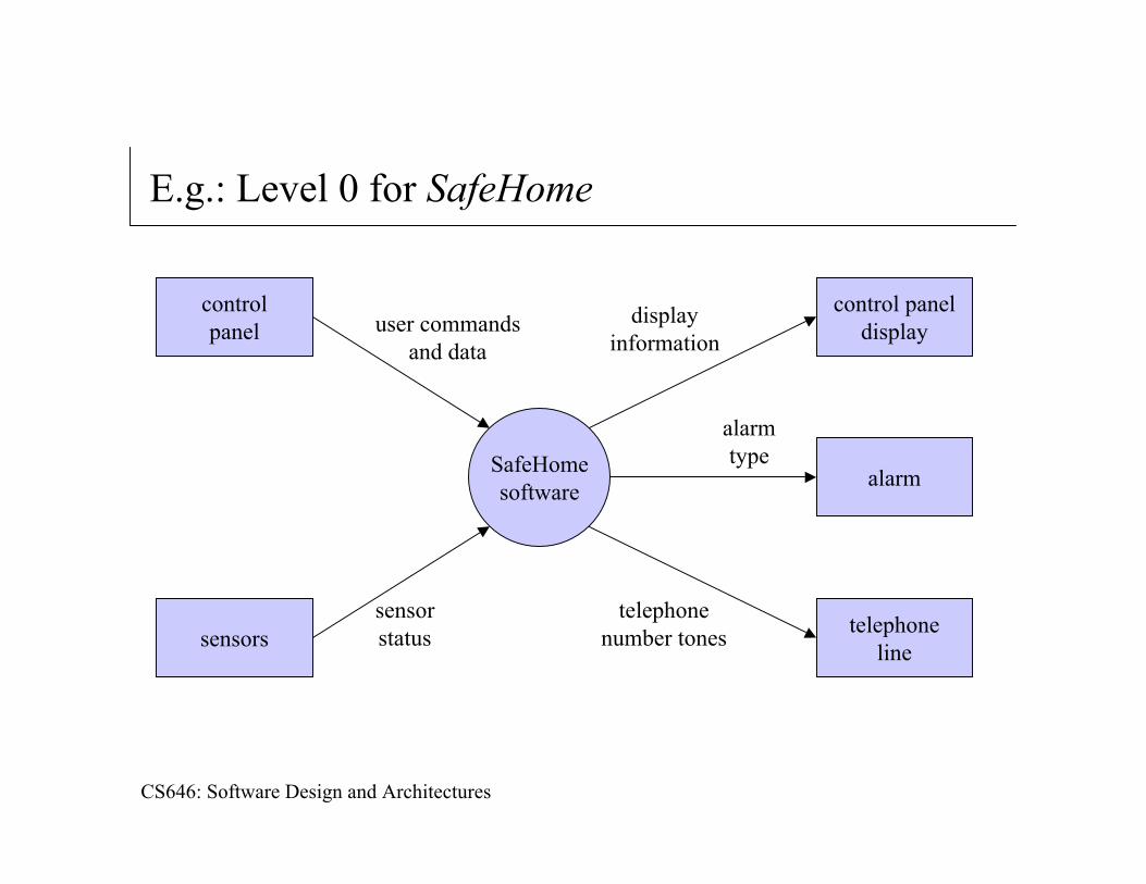
E.g.: Level 0 for SafeHome
SafeHomesoftware
controlpanel
sensors telephoneline
alarm
control paneldisplayuser commands
and data
sensorstatus
displayinformation
alarmtype
telephonenumber tones
CS646: Software Design and Architectures
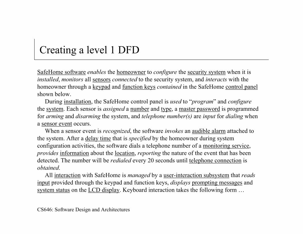
Creating a level 1 DFD
SafeHome software enables the homeowner to configure the security system when it is installed, monitors all sensors connected to the security system, and interacts with the homeowner through a keypad and function keys contained in the SafeHome control panelshown below.
During installation, the SafeHome control panel is used to “program” and configurethe system. Each sensor is assigned a number and type, a master password is programmed for arming and disarming the system, and telephone number(s) are input for dialing when a sensor event occurs.
When a sensor event is recognized, the software invokes an audible alarm attached to the system. After a delay time that is specified by the homeowner during system configuration activities, the software dials a telephone number of a monitoring service, provides information about the location, reporting the nature of the event that has been detected. The number will be redialed every 20 seconds until telephone connection is obtained.
All interaction with SafeHome is managed by a user-interaction subsystem that readsinput provided through the keypad and function keys, displays prompting messages and system status on the LCD display. Keyboard interaction takes the following form …
CS646: Software Design and Architectures
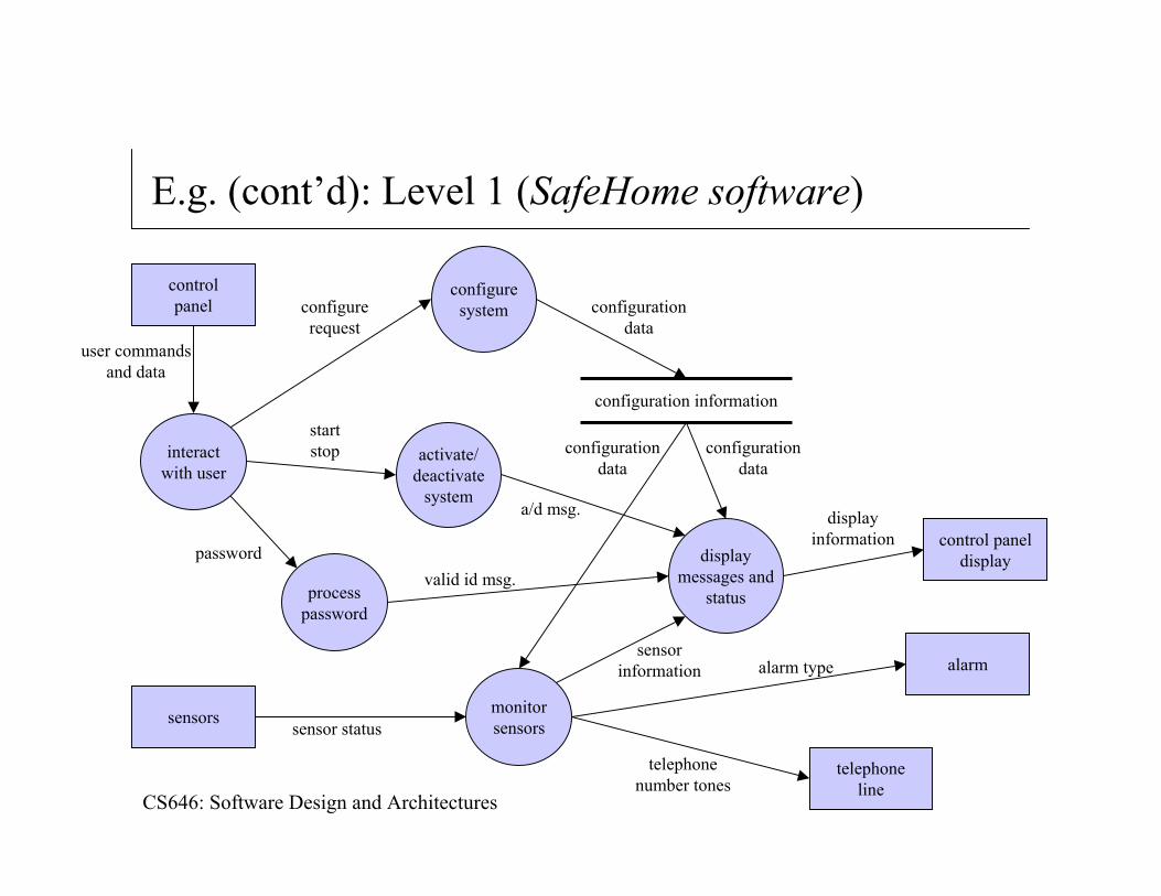
E.g. (cont’d): Level 1 (SafeHome software)
user commandsand data
controlpanel
sensors
telephoneline
alarm
control paneldisplay
displayinformation
configuresystem
interactwith user
processpassword
activate/deactivate
system
displaymessages and
status
monitorsensors
configuration information
password
configurerequest
startstop
configurationdata
a/d msg.
valid id msg.
configurationdata
configurationdata
sensorinformation alarm type
telephonenumber tones
sensor status
CS646: Software Design and Architectures
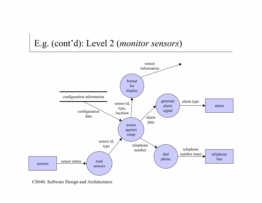
E.g. (cont’d): Level 2 (monitor sensors)
sensors
telephoneline
alarm
formatfor
display
generatealarmsignal
assessagainstsetup
readsensors
configuration information
configurationdata
sensor id,type
alarm type
telephonenumber tones
sensor status
dialphone
sensorinformation
telephonenumber
alarmdata
sensor id,type,
location
CS646: Software Design and Architectures
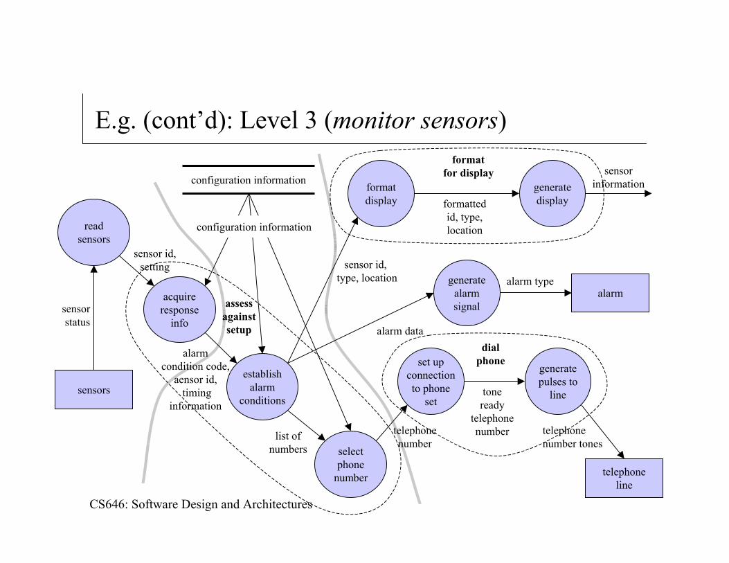
E.g. (cont’d): Level 3 (monitor sensors)
sensors
telephoneline
alarm
formatdisplay
generatealarmsignal
establishalarm
conditions
readsensors
configuration information
alarm type
telephonenumber tones
sensorstatus
generatepulses to
line
sensorinformation
telephonenumber
alarm data
sensor id, type, location
generatedisplay
acquireresponse
info
selectphone
number
set upconnectionto phone
set
formattedid, type,location
toneready
telephonenumberlist of
numbers
alarmcondition code,
aensor id,timing
information
sensor id,setting
configuration information
assessagainstsetup
dialphone
formatfor display
CS646: Software Design and Architectures
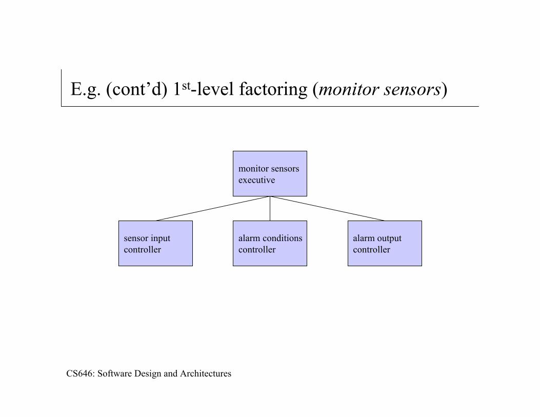
E.g. (cont’d) 1st-level factoring (monitor sensors)
monitor sensorsexecutive
sensor inputcontroller
alarm conditionscontroller
alarm outputcontroller
CS646: Software Design and Architectures
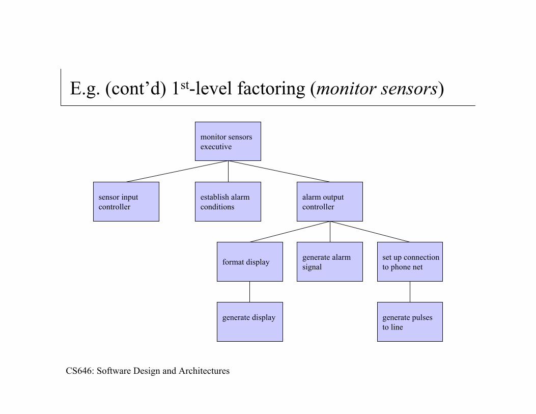
E.g. (cont’d) 1st-level factoring (monitor sensors)
monitor sensorsexecutive
sensor inputcontroller
establish alarmconditions
alarm outputcontroller
format display generate alarmsignal
set up connectionto phone net
generate pulsesto line
generate display
CS646: Software Design and Architectures
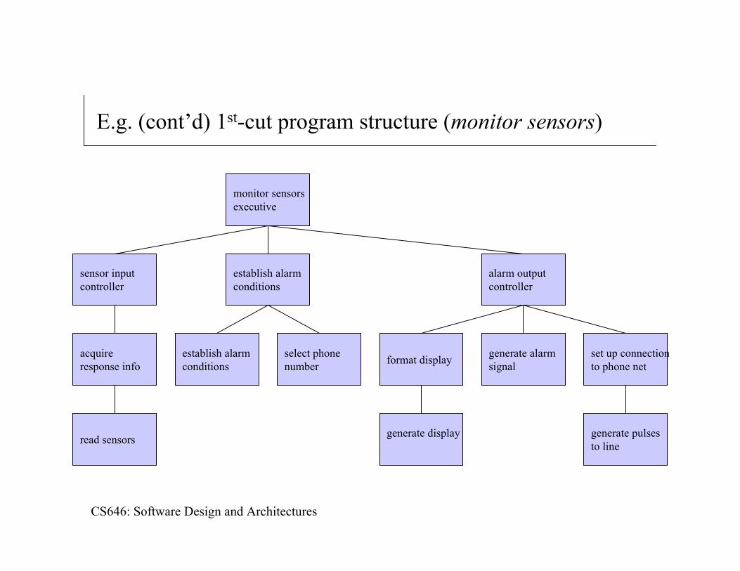
E.g. (cont’d) 1st-cut program structure (monitor sensors)
monitor sensorsexecutive
sensor inputcontroller
establish alarmconditions
alarm outputcontroller
format display generate alarmsignal
set up connectionto phone net
generate pulsesto line
generate display
select phonenumber
establish alarmconditions
read sensors
acquireresponse info
CS646: Software Design and Architectures
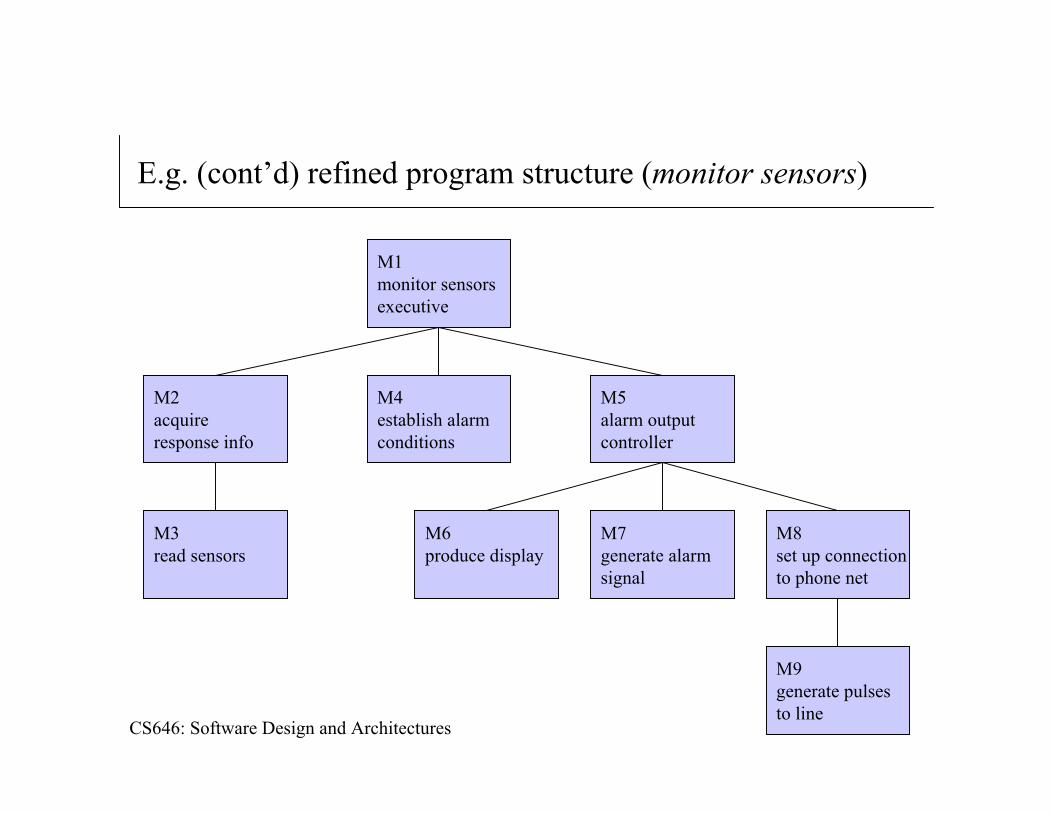
E.g. (cont’d) refined program structure (monitor sensors)
M1monitor sensorsexecutive
M2acquireresponse info
M4establish alarmconditions
M5alarm outputcontroller
M6produce display
M7generate alarmsignal
M8set up connectionto phone net
M9generate pulsesto line
M3read sensors
CS646: Software Design and Architectures
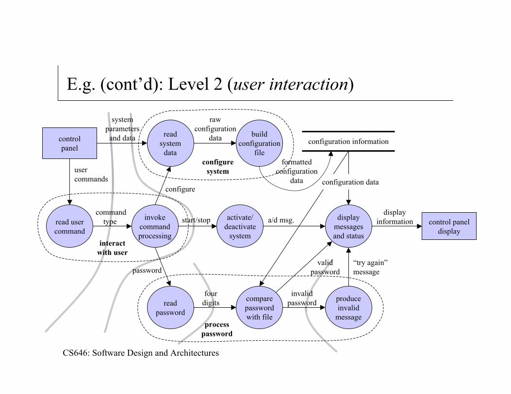
E.g. (cont’d): Level 2 (user interaction)
controlpanel
control paneldisplay
displayinformation
readsystem
data
invokecommandprocessing
readpassword
configuration information
commandtype
formattedconfiguration
data
a/d msg.
comparepasswordwith file
produceinvalid
message
buildconfiguration
file
read usercommand
activate/deactivate
system
displaymessagesand status
start/stop
rawconfiguration
data
“try again”message
validpassword
invalidpassword
fourdigits
usercommands
systemparameters
and data
password
configuration dataconfigure
configuresystem
interactwith user
processpassword
CS646: Software Design and Architectures
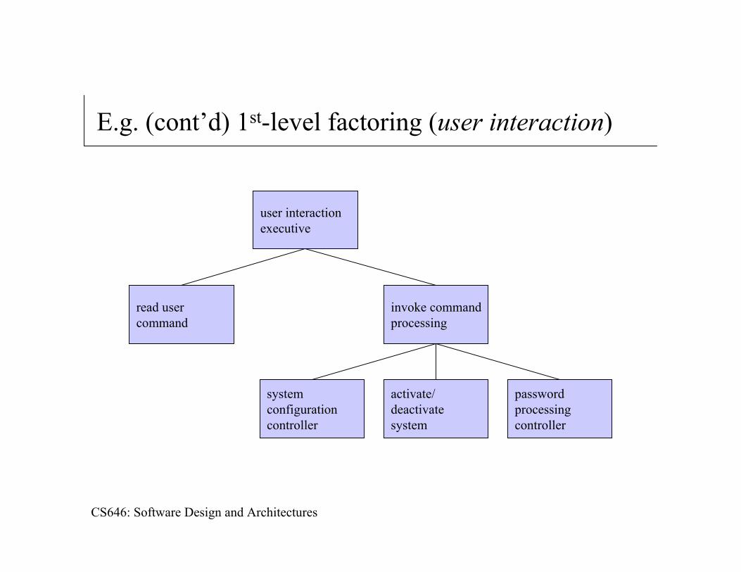
E.g. (cont’d) 1st-level factoring (user interaction)
user interactionexecutive
read usercommand
invoke commandprocessing
passwordprocessingcontroller
activate/deactivatesystem
systemconfigurationcontroller
CS646: Software Design and Architectures
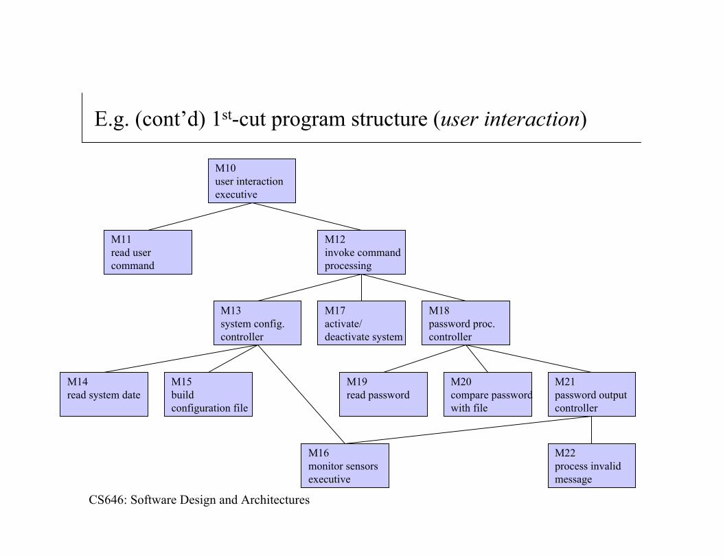
E.g. (cont’d) 1st-cut program structure (user interaction)
M10user interactionexecutive
M11read usercommand
M12invoke commandprocessing
M18password proc.controller
M17activate/deactivate system
M13system config.controller
M14read system date
M15buildconfiguration file
M16monitor sensorsexecutive
M19read password
M20compare passwordwith file
M21password outputcontroller
M22process invalidmessage