Embed Size (px)
Citation preview

TRANSFORMER GUIDE75W | 150W | 300W

INSTRUCTIONS APPLY TO MODELS: 75W, 150W & 300W
SAFETY: This fixture must be installed in accordance with the National Electric Code and local code specifications. Failure to follow these codes and installation instructions will void the warranty and may result in serious injury and/or damage to the fixture. This product is designed for above ground installation only. Keep these instructions for future use.
-WARNING! Risk of fire or electrical shock. Install the transformer at least 5 feet (1.5m) from pool or spa and at least 10 feet (3.05m) from a fountain.-This transformer must be connected to GUCCI-protected receptacle. If the receptacle is outdoors then it must be protected by an in-use weather-proof cover.-All transformers are indoor and outdoor rated, but we recommend the transformer be mounted outdoors. If mounted indoors, then codes should be followed that apply to indoor wiring - especially for wires that pass through exterior walls.-Transformer must be mounted in a vertical orientation with the bottom plate at least 1 foot from ground.-It is normal for the unit to become hot, do not allow contact with PVC or plastic sidings. In hot climates, avoid mounting in direct sunlight, but allow photocell to be exposed to sky. Near salt-water, protect unit by enclosing in weather-proof structure.
CIRCUIT BREAKER: This product has a built in circuit breaker to help protect against electrical short circuits. This does not prevent the need to use GFCI outlets marked for “wet location.” It also does not prevent the requirement to follow all local and electrical building codes for the main circuit breaker protection.
If a circuit break occurs, immediately disconnect the transformer from the power source. Make all repairs to the lighting system that cause the circuit breaker to trip. Once the problem has been determined and fixed, reset the breaker by switching to the on position.
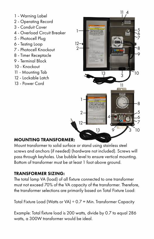
1 - Warning Label2 - Operating Record3 - Conduit Cover4 - Overload Circuit Breaker5 - Photocell Plug6 - Testing Loop7 - Photocell Knockout8 - Timer Receptacle9 - Terminal Block10 - Knockout11 - Mounting Tab12 - Lockable Latch13 - Power Cord
MOUNTING TRANSFORMER:Mount transformer to solid surface or stand using stainless steel screws and anchors (if needed) (hardware not included). Screws will pass through keyholes. Use bubble level to ensure vertical mounting. Bottom of transformer must be at least 1 foot above ground.
TRANSFORMER SIZING:The total lamp VA (load) of all fixture connected to one transformer must not exceed 70% of the VA capacity of the transformer. Therefore, the transformer selections are primarily based on Total Fixture Load:
Total Fixture Load (Watts or VA) ÷ 0.7 = Min. Transformer Capacity
Example: Total fixture load is 200 watts, divide by 0.7 to equal 286 watts, a 300W transformer would be ideal.
1
2
3
1
2
3
4
4
5
56
67
7
8
8
9
9
10
10
11
11
12
12
13
13

SELECT YOUR WIRE:We recommend using 12 AWG low voltage direct landscape wire. It is important to distribute fixtures evenly along the cable with higher wattage fixtures closer to the transformer if possible. Only use the bottom terminals for wiring to the light source. Do not loosen the top terminals. They are for internal wiring of the transformer. The higher voltage terminals are for long wire runs to lights. These will help account for voltage loss along the long run of wire.
Voltage Loss Calculation( distance [ft] X load [W] X 2 ) ÷ cable constant = voltage loss
Wire Gauge Cable Constant#18/2 1380#16/2 2200#14/2 3500#12/2 7500#10/2 11920
SELECT VOLTAGE TAPS:Transformers are Multi-Tap - giving you a selection of voltages for your wire run connections. Selecting a higher voltage at the transformer compensates for voltage that may be lost along wire runs.

Remove the nut from the photo cell & unplug the jumper connection from the transformer.
INSTALLING A PHOTOCELL:Disconnect the source power to the transformer before installing the photo cell. Remove the inner knockout located on the side of the transformer. Do not remove the outer portion of the knockout or the photo cell will not fit properly.
Insert the wire & connector of the photo cell through the hole in the side of the transformer. Place the nut around the wire & screw onto the photo cell, holding the unit in position.
Plug the photo cell into the now empty socket
To remove the inner portion, use a screw driver to bend the tabs forward. Once both tabs are bent forward, use a set of pliers to twist and bend the tabs until the inner knockout breaks loose.
75W
75W
150/300W
150/300W
150/300W
75W
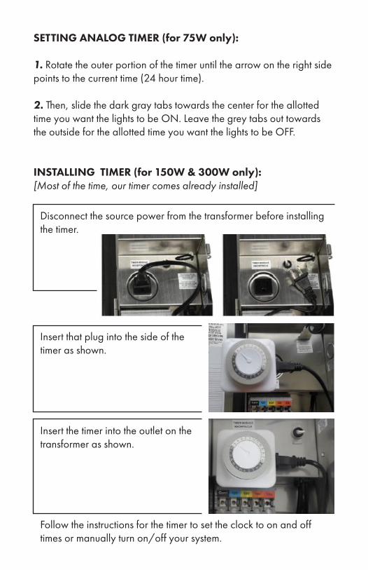
SETTING ANALOG TIMER (for 75W only):
1. Rotate the outer portion of the timer until the arrow on the right side points to the current time (24 hour time).
2. Then, slide the dark gray tabs towards the center for the allotted time you want the lights to be ON. Leave the grey tabs out towards the outside for the allotted time you want the lights to be OFF.
INSTALLING TIMER (for 150W & 300W only):[Most of the time, our timer comes already installed]
Disconnect the source power from the transformer before installing the timer.
Insert that plug into the side of the timer as shown.
Insert the timer into the outlet on thetransformer as shown.
Follow the instructions for the timer to set the clock to on and off times or manually turn on/off your system.
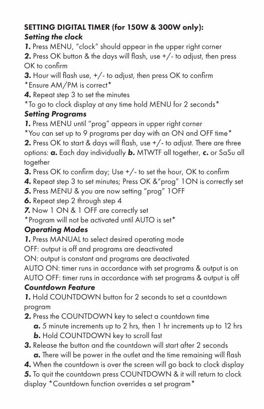
SETTING DIGITAL TIMER (for 150W & 300W only):Setting the clock1. Press MENU, “clock” should appear in the upper right corner2. Press OK button & the days will flash, use +/- to adjust, then press OK to confirm3. Hour will flash use, +/- to adjust, then press OK to confirm *Ensure AM/PM is correct*4. Repeat step 3 to set the minutes*To go to clock display at any time hold MENU for 2 seconds*Setting Programs1. Press MENU until “prog” appears in upper right corner *You can set up to 9 programs per day with an ON and OFF time*2. Press OK to start & days will flash, use +/- to adjust. There are three options: a. Each day individually b. MTWTF all together, c. or SaSu all together3. Press OK to confirm day; Use +/- to set the hour, OK to confirm4. Repeat step 3 to set minutes; Press OK &“prog” 1ON is correctly set5. Press MENU & you are now setting “prog” 1OFF6. Repeat step 2 through step 47. Now 1 ON & 1 OFF are correctly set *Program will not be activated until AUTO is set*Operating Modes1. Press MANUAL to select desired operating modeOFF: output is off and programs are deactivatedON: output is constant and programs are deactivated AUTO ON: timer runs in accordance with set programs & output is onAUTO OFF: timer runs in accordance with set programs & output is offCountdown Feature1. Hold COUNTDOWN button for 2 seconds to set a countdown program2. Press the COUNTDOWN key to select a countdown time a. 5 minute increments up to 2 hrs, then 1 hr increments up to 12 hrs b. Hold COUNTDOWN key to scroll fast3. Release the button and the countdown will start after 2 seconds a. There will be power in the outlet and the time remaining will flash4. When the countdown is over the screen will go back to clock display5. To quit the countdown press COUNTDOWN & it will return to clock display *Countdown function overrides a set program*

7202 E Cave Creek Rd, Suite 3A | PO Box 2281 | Carefree, AZ 85377(800) 867-2108 | www.brillianceled.com