Embed Size (px)
Citation preview

Page 1 of 1
Increase transformer reliability and availability:
From Condition Assessment to Site Repair
By
Pierre Lorin, Lars Eklund, Peter Werle, Ekkehard Zeitz ABB Ltd Transformer Service

Page 2 of 2
Page 3 of 3
Increase transformer reliability and availability: From Condition Assessment to Site Repair
Pierre Lorin Lars Eklund Peter Werle Ekkehard Zeitz
ABB Ltd Transformer Service 1. Abstract
Over the last decade there has been a renewed and increased interest in transformer life
evaluation and monitoring. The main reason is that a large number of the transformers world
population is approaching its expected end-of-life and the need increases for better methods
to see whether the transformers are still fit for use or need to be retrofitted or replaced.
In case of failure the possibility to reduce the outage time is usually important for the
transformer owner.
In this paper we will therefore describe MTMPTM - ABB’s condition assessment
methodology - as well as TrafoSiteRepairTM - ABB’s on-site repair solution – as means to
increase both the reliability and availability of transformers and therefore the energy
efficiency of the network.
The output of such a MTMPTM survey is a ranking of the population with priorities for
investment and recommended maintenance actions plan for each unit.
The advanced diagnosis of the transformer condition is used to identify defects before even
untanking the transformer and therefore is from great support in order to speed up repair time
especially in the case when a transformer is repaired at site.
If a transformer has to be repaired the time for transportation of the unit to a transformer
factory will have a major influence on when it can be put back in service. Also the cost and
risk of such a heavy transport has to be considered.
Since some years ABB started to develop processes to perform also major repair, including
replacement of windings and repair of the core at site. To date a total of more than 200 units
including utility, industrial and HVDC transformers and reactors have been repaired. In
many cases units were also upgraded to provide an increased rating.
By introducing on the market MTMPTM and TrafoSiteRepairTM two state-of-the-art
technologies combined with extensive experience, ABB can offer today even greater speed,
minimizing the outage time of the transformer and unavailability of the power supply in order
to maximize revenues for the owner.
Page 4 of 4
2. Introduction How to keep aged assets up running at a minimum Total Cost of Ownership while ensuring a
requested reliability?
This question is the challenge that each and every asset manager face in his daily work.
Transformers are a large part of the asset cost structure of the power system. With increasing
financial pressure on utilities, the trend is to use existing units as long and hard as possible
without putting the reliability of the system at risk. For critical transformers, the
consequential cost of a failure can easily exceed the value of the transformer itself by one or
two orders of magnitude.
In this perspective, assets managers are exposed to solving a complex equation that involves
both technical and economical criterions. The capability to make a correct condition
assessment of the equipment is essential to meet the goals of maximizing return on
investment, reducing costs associated to possible loss of production [1] and lowering total
Life Cycle Costs.
Transformer asset management, which relies mainly on condition assessment study outputs
combined with financial evaluations, will then be the main decision driver in future planning
and budgeting either for maintenance strategy, retrofit or replacement purpose.
To fully gain the advantages of the condition assessment of the assets any measures required
should be performed in as short period of time as possible. The development of processes to
perform also advanced repair and retrofit at the site has made it possible to now reduce the
down time in such cases considerably.
3. Understand the status of the assets and define risk mitigation actions: MTMProgramTM (Mature Transformer Management Program) A statistical approach based on international figures about transformer reliability is useful in
a first step to setup rough maintenance and investment budgets. However, ABB’s experience
shows that each unit should be considered as a specific case once the user need to decide
about precise maintenance actions or wants to take solid decisions to relocate, retrofit or
replace the unit by a new one.
Page 5 of 5
The method presented here is a modular approach to meet different levels of expectation
defined by the end-user in term of population’s size, level of information requested and
budget available.
The strategy we have taken for the evaluation is to identify the most critical transformers and
use a fast screening to reduce the number of concerned units to be studied closer. The
ambition level will then judge how deep the investigation should go. Our evaluation
approach has been to make the evaluation in steps [2]. It is not necessary to spend efforts on
units that are very well suited for their purpose or which looks to be in a very good shape.
The steps are normally linked together in order to reuse the information gained in an earlier
step. The assessment methodology is then based on the three steps described below:
Step 1: Fleet Screening
This is a quick scanning of a large population (20 – 200 units) using easily accessible data
such as name plate data from the units, oil and dissolved gas in oil data, load profile and
history of the unit (maintenance, operation and events).
One idea with this step is to reduce the number of units, which could be of interest for further
deeper studies. All units that look normal do not need to be treated further. This also means
that the ambition level is reduced.
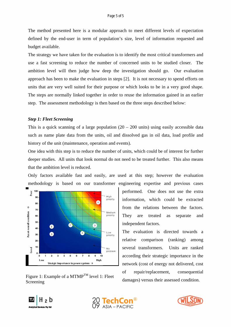
Only factors available fast and easily, are used at this step; however the evaluation
methodology is based on our transformer engineering expertise and previous cases
performed. One does not use the extra
information, which could be extracted
from the relations between the factors.
They are treated as separate and
independent factors.
The evaluation is directed towards a
relative comparison (ranking) among
several transformers. Units are ranked
according their strategic importance in the
network (cost of energy not delivered, cost
of repair/replacement, consequential
damages) versus their assessed condition. Figure 1: Example of a MTMPTM level 1: Fleet Screening

Page 6 of 6
This first step provides higher-level management and asset managers with a cockpit view of
their assets as shown on Figure 1. It gives relevant inputs for maintenance or investment
budget strategy. It is also used to select units that must be further investigated either because
they are strategic units or because they are in a critical status.
Step 2: Life Assessment
The experts here focus on a smaller number of units (10 to 20 units) identified during step 1.
The normal evaluation step needs more information. It uses the results from the screening
evaluation, but adds some calculations, site inspections and measurements. Experts use
modern design rules and tools to evaluate the original design. Advanced diagnosis tests [3]
are performed (DGA, Furanes, Frequency Response Analysis, Dielectric Response, Partial
Discharge) to assess each of the main properties of the transformer in a structured way:
mechanical status, thermal status and ageing of the insulation, electrical status of the active
part as well as the condition of the accessories such as tap changer(s), bushings, over-pressure
valves, air-dryer system, pumps and relays.
In terms of serviceability the end user gets richer information since a ranking is done on
different criteria for each of the key properties. For example a transformer could be suitable
to withstand overload but not short circuit.
Taking into account the results of this detailed assessment, the experts elaborate for each unit
an action plan to improve each key properties and as a result their overall reliability.
Assets, maintenance and operation managers take full benefits of this second part of the
survey. Valuable inputs (see Figure 2) - such as a list of spare parts to be kept in stock, a list
of maintenance actions to be done at site with clear priorities, proposals to relocate or deload
units, to repair or change for new - will help them strengthening their daily decisions with
solid understanding and explanations.

Page 7 of 7
Unit # Mechanical Electrical Thermal Accessories Overall Actions
TFO 2 Winding Arcing Heating 95
TFO 5 Tank OLTC heating 80
TFO 1 Aged oil Bushing 70
TFO 6 Arcing Thermometer 50
TFO 3 Silicagel 40
TFO 7 25
TFO 8 15
TFO 4 10
Plant 1 - Results of condition assessement step 2 and action plan
Oil regeneration / filtration and advanced diagnosis / change HV bushing
Visual Inspection and repair in factory / rewinding
Standard maintenance actions and controls / 10 % overload capabilities
Standard maintenance actions and controls / 15 % overload capabilities
Exchange TopOil - thermometer / on line monitoring of DGA
Repair on site and OLTC overhaul
Exchange Silicagel
Standard maintenance actions and controls
Figure 2: Result of MTMProgramTM level 2: Life Assessment on eight transformers
Step 3: Risk Assessment
This last step uses the data from step 2 but adds some more data and extra analysis (Fig. 3).
The number of units to be further analyzed is usually limited to two or three out of a
population of 100 units. International experts are involved using state of the art simulation
tools to perform thermal simulations such as hot spot and ageing, mechanical calculations
such as short-circuit withstand and electro-magnetic field computations.
Design-Based Data Loading andOperational History
Diagnostic andMaintenance Records
Output
Figure 3: Chart illustrating the structure of a Risk Assessment survey using the influence
between the different evaluation criteria.
Page 8 of 8
The goal is then to define weak points of the units that need to be improved in order to meet
defined serviceability constraints.
The assessment is here very detailed and provides a deep evaluation of each main properties
including remaining life time and risks in operation.
This third module within the assessment process provide accurate information to the end-
user’s engineering manager that want to overload a transformer, upgrade a unit to increase its
nominal power [4] or voltage rating, or extend its life time.
It could also be used to understand root causes after failures and support decisions related to
the possibility of a workshop or site repair [5].
4. Repair of Power Transformers at Site
As discussed above the increased age of the installed base of transformers has increased the
interest for assessment of the condition of the transformers. The above described program for
condition assessment will assist the owner of the transformers to take early measures to
prevent failures that may require an extensive repair or a replacement of the transformer.
However with the aging stock of transformers also the failure rate of transformers will
increase and create an increased demand for repair or replacement of units. The result of the
condition assessment and a required increase of production or transmission of power may
also lead to decision to upgrade the rating of transformers. Such an upgrade will normally
include replacement of the windings and insulation and also an upgrade of the cooling
system.
A repair or refurbishment of a power transformer not requiring winding replacement or
another major action is normally performed at site. However, when a major repair or upgrade
has been required in the past the transformer has been transported to a transformer factory
where the required space and equipment were available.
For a large transformer the transportation will have a major influence on the time until the
transformer can be put back in service and the capacity be restored. Such heavy
transportation may also be very risky. In some cases it may not even be possible to get the

Page 9 of 9
transformer to a transformer workshop due to changes of the infrastructure that not any
longer support the transportation of the heavy loads of large power transformers.
To reduce the outage time of a failed transformer and to solve the difficult cases when
transportation is not possible site repair offers a solution. It will save time and avoid risks of
transportation damages. However, a repair of a large power transformer is a demanding
process, requiring clean environment, highly qualified workmanship, an advanced drying
process and verifying high voltage dielectric tests. Would all this be possible to fulfill at
remote site far away from the well organized transformer factory?
In the middle of the ‘80-ties this was a challenge taken by ABB and some utilities for the first
time. Since then the site repair concept has been developed to be an important alternative to
increase the availability of transformers, power generation plants and sub-stations.
Until a few years ago site repair was mainly performed by ABB in three countries, Brazil,
Italy and Spain. Today, the TrafoSiteRepairTM is a concept being developed to be applied
globally and since the successful first projects were performed some 20 years ago, more than
200 transformers have been repaired successfully on-site in 25 different countries.
4.1 The TrafoSiteRepairTM process Power transformer factories and workshops are characterized by their orderliness, cleanliness
and well controlled atmospheres which are conditions required for manufacturing and repair
of high voltage equipment. They also possess heavy lifting equipment, special tools and
fixtures, high voltage test laboratories and experienced and well trained operators for each
step of the process.
To perform a site repair of a transformer, the same capabilities have to be set up at site to
meet the individual circumstances of each case. The ABB TrafoSiteRepairTM concept will
include:
• As a site repair should be performed in a controlled environment it should be
performed indoors, in a facility where the required levels of cleanliness and
orderliness may achieved. The facility should as far as possible, allow for the
performance of all critical steps of the repair inside the facility. If the customer does
not have a repair area a temporary workshop will be set up.

Page 10 of 10
• Heavy lifting equipment will be brought to the site. The largest transformers may
require a capacity of up to 400 metric tons for untanking and tanking of the active
part. If the customer possesses a maintenance area which may be used for the repair
an overhead crane may be available.
• The same type of tools and equipment as used in a factory are brought to the site and
used for the repair.
• Maintaining low moisture content of the insulation is of highest importance for the
result of the repair. Windings and insulation components are manufactured at a
transformer factory and are dried and impregnated prior to shipment. They are then
specially packed to maintain the low moisture content and shipped for assembly at
site.
• Following the complete assembly of the active part it is tanked and prepared for final
drying. The On-Site Drying process will reduce the moisture level to below 1 %.
There are several methods available for On-Site Drying. To further save time of the
repair a special method for On-Site Drying has been developed by ABB
• High voltage test of the assembled transformer is carried out on-site according to the
agreed test schedule. To meet the requirement of portability and flexibility an On-Site
High Voltage test system has been developed together with a test equipment supplier.
4.2 Facilities for TrafoSiteRepairTM
Temporary workshops
Based on the experience gained within the ABB Service centers that have performed site
repair projects a maintenance shop owned by the customer is available for approximately
50% of the repair projects. Those may also be equipped with an overhead crane for lifting of
active parts and winding blocks. For the remaining 50% of the projects it is necessary to set
up a temporary facility. When a permanent facility is available at site to be used for the
transformer repair it should be separated from the rest of the facility to maintain the
cleanliness required.
A temporary workshop may be set up based on a steel structure with a cladding of corrugated
sheets of steel or aluminum. This type of building is primarily used when more that one
transformer will be repaired at the same site or when there is a desire to keep the building for
any future repair or maintenance.

Page 11 of 11
Figure 4: A steel building used as temporary workshop by ABB in Brazil for TrafoSiteRepairTM
Another very flexible solution is to use a large tent consisting of a steel structure and
claddings of flexible sheet material such as PVC giving a tight facility where it is possible to
keep an excellent environment for the work on the active part of the transformer. These types
of tents may be set up in very short time, normally less than a week. They are also designed
to withstand severe weather conditions such strong winds and snow load.
Figure 5: Typical tent structure that may be used as temporary workshop for TrafoSiteRepairTM
Heavy lifting at site The major heavy lifting during repair of a core type transformer is the lifting of the active
part for untanking and tanking of the transformer. The active part of the largest transformers
may weigh up to 400 metric tons. To handle this weight, mobile compact lifting systems are

Page 12 of 12
and other
components for disassembly and reassembly of the active part and the transformer
available from global suppliers. For smaller transformers the lifting of the active part may be
performed with mobile cranes which are also used for lifting of windings
Figure 6: Tanking of large power transformer using mobile lifting equipment
tory the guideline for the ABB
d, the same criteria for
red maximum level of moisture content. These alternative processes are
escribed below.
4. 3 The factory is brought to site For achieving the same quality of repair at site as repair in fac
TrafoSiteRepairTM concept is: “We bring the factory to site”.
That means that the repair should be performed in the same way at site as in the factory. The
same processes, tools, fixtures and equipment shall be used as far as possible. For tools and
fixtures this rule can normally be followed to 100%. When the factory processes or
equipment may not be used and an alternative has to be applie
successfully performed process should be applied as in the factory.
One process used in factory which not is used at site is the drying of the active part using the
vapor-phase process. However based on the experience and detailed investigations of the
result from a large number of projects the drying result of the alternative processes used is
fulfilling the requi
d
Page 13 of 13
4. 4 On-Site Drying Initially, all new windings and insulating components internal to the transformer are dried
and impregnated while still in the factory. The oil impregnation is a protection against
moisture absorption when handling the parts. In addition all parts are specially packed or
transported with special containers that are filled with dry oil or dry air. On site the new parts
and the transformer are stored under controlled climatic conditions. Air drying units
guarantee the best possible condition to prevent moisture ingress during the repair.
Once the repair is finished, an on site drying process is initiated after the assembly and
tanking of the transformer’s active part. The on site drying includes a heating of the whole
transformer succeeded by vacuum cycles.
Typical processes used:
• Hot oil circulation: Hot oil is circulated through the transformer and once the desired
temperature is reached the oil is emptied into a tank and vacuum is applied. As the
transformer will cool down during the vacuum phase several cycles are needed. Also
the maximum allowed oil temperature may limit the maximum drying temperature.
• Hot oil spray: Spray nozzles are installed at the available flanges and hot oil is
sprayed over the active part at the same time as vacuum is applied. This allows
limiting the temperature reduction during the vacuum cycles. But due to design of the
core type transformers with press plates and shieldings, it might be difficult to heat up
the whole transformer uniformly. For shell type transformer this method is more
often used as the main insulation can be easily reached by the hot oil spray.
• Low frequency current heating (LFH) in combination with hot oil spray: In order to
heat up both low and high voltage windings, a frequency of approx. 1 Hz is applied
to the transformer. With the combination of LFH drying and the conventional hot oil
spray method, the whole transformer can be heated very uniform. The LFH system is
heating the windings from the inside and the hot oil spray supports the heating process
by heating outer parts of the insulation system.
Page 14 of 14
The LFH process combined with hot oil spray allows to reduce the drying time essentially. It
is possible to reach the same low levels of moisture in the whole insulation as with a factory
repair within approx. 1 week. Compared to “conventional” systems like oil circulation or hot
oil spray, this is a time reduction by approximately a factor of 4.
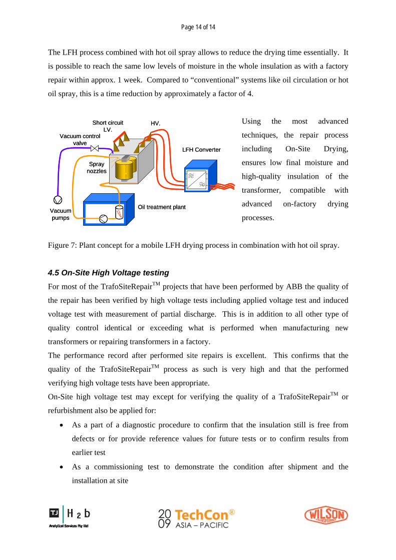
Using the most advanced
techniques, the repair process
including On-Site Drying,
ensures low final moisture and
high-quality insulation of the
transformer, compatible with
advanced on-factory drying
processes.
LFH Converter
Oil treatment plant
Short circuitLV.
HV.
Vacuumpumps
Vacuum control valve
Spray nozzles
LFH Converter
Oil treatment plant
Short circuitLV.
HV.
Vacuumpumps
Vacuum control valve
Spray nozzles
Figure 7: Plant concept for a mobile LFH drying process in combination with hot oil spray.
4.5 On-Site High Voltage testing For most of the TrafoSiteRepairTM projects that have been performed by ABB the quality of
the repair has been verified by high voltage tests including applied voltage test and induced
voltage test with measurement of partial discharge. This is in addition to all other type of
quality control identical or exceeding what is performed when manufacturing new
transformers or repairing transformers in a factory.
The performance record after performed site repairs is excellent. This confirms that the
quality of the TrafoSiteRepairTM process as such is very high and that the performed
verifying high voltage tests have been appropriate.
On-Site high voltage test may except for verifying the quality of a TrafoSiteRepairTM or
refurbishment also be applied for:
• As a part of a diagnostic procedure to confirm that the insulation still is free from
defects or for provide reference values for future tests or to confirm results from
earlier test
• As a commissioning test to demonstrate the condition after shipment and the
installation at site
Page 15 of 15
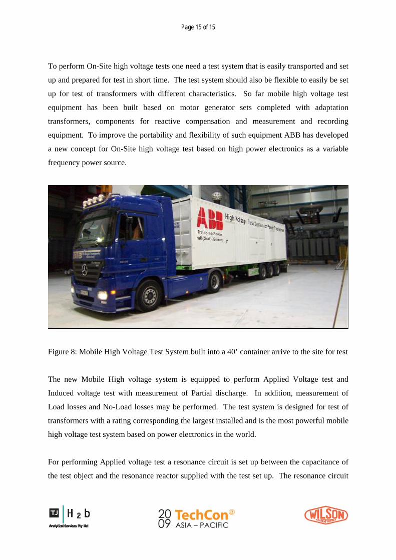
To perform On-Site high voltage tests one need a test system that is easily transported and set
up and prepared for test in short time. The test system should also be flexible to easily be set
up for test of transformers with different characteristics. So far mobile high voltage test
equipment has been built based on motor generator sets completed with adaptation
transformers, components for reactive compensation and measurement and recording
equipment. To improve the portability and flexibility of such equipment ABB has developed
a new concept for On-Site high voltage test based on high power electronics as a variable
frequency power source.
Figure 8: Mobile High Voltage Test System built into a 40’ container arrive to the site for test
The new Mobile High voltage system is equipped to perform Applied Voltage test and
Induced voltage test with measurement of Partial discharge. In addition, measurement of
Load losses and No-Load losses may be performed. The test system is designed for test of
transformers with a rating corresponding the largest installed and is the most powerful mobile
high voltage test system based on power electronics in the world.
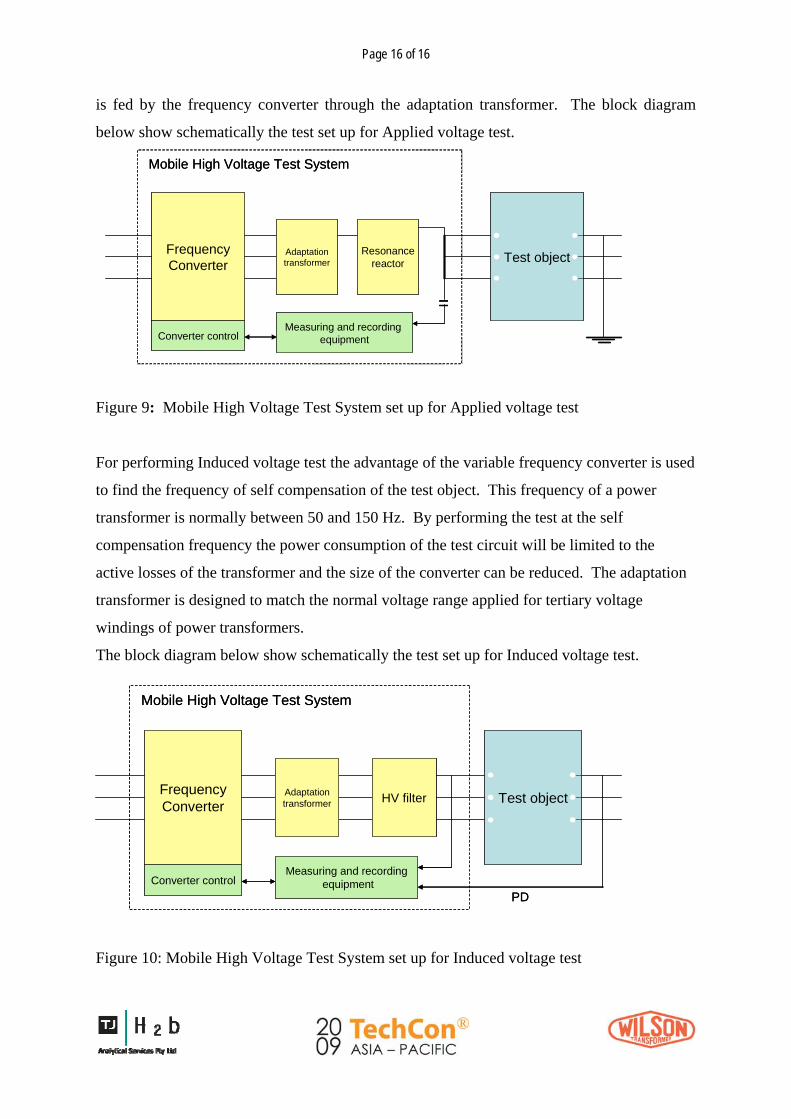
For performing Applied voltage test a resonance circuit is set up between the capacitance of
the test object and the resonance reactor supplied with the test set up. The resonance circuit
Page 16 of 16
is fed by the frequency converter through the adaptation transformer. The block diagram
below show schematically the test set up for Applied voltage test.
FrequencyConverter
Adaptationtransformer
Resonancereactor Test object
Measuring and recording equipmentConverter control
Mobile High Voltage Test System
=
FrequencyConverter
Adaptationtransformer
Resonancereactor Test object
Measuring and recording equipmentConverter control
Mobile High Voltage Test System
=
Figure 9: Mobile High Voltage Test System set up for Applied voltage test
For performing Induced voltage test the advantage of the variable frequency converter is used
to find the frequency of self compensation of the test object. This frequency of a power
transformer is normally between 50 and 150 Hz. By performing the test at the self
compensation frequency the power consumption of the test circuit will be limited to the
active losses of the transformer and the size of the converter can be reduced. The adaptation
transformer is designed to match the normal voltage range applied for tertiary voltage
windings of power transformers.
The block diagram below show schematically the test set up for Induced voltage test.
FrequencyConverter
Adaptationtransformer HV filter Test object
Measuring and recordingequipmentConverter control
PD
Mobile High Voltage Test System
FrequencyConverter
Adaptationtransformer HV filter Test object
Measuring and recordingequipmentConverter control
PD
Mobile High Voltage Test System
Figure 10: Mobile High Voltage Test System set up for Induced voltage test
Page 17 of 17
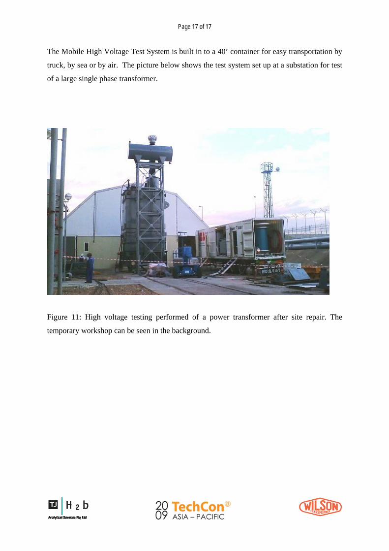
The Mobile High Voltage Test System is built in to a 40’ container for easy transportation by
truck, by sea or by air. The picture below shows the test system set up at a substation for test
of a large single phase transformer.
Figure 11: High voltage testing performed of a power transformer after site repair. The
temporary workshop can be seen in the background.

Page 18 of 18
5. Transformer repaired at site in the Philippines using the ABB TrafoSiteRepairTM technology
A Generator Step Up Transformer (GSU) located in Limay Bataan, Philippines failed in
service. The power plant is owned by the National Power Corporation (NPC) in the
Philippines and operated by Alstom
Power. The operator did not have
any spare transformers and required
the quickest option to repair and
return the GSU to service.
Initial electrical measurements and
oil analysis indicated that the
windings of the transformer were
damaged and needed to be replaced.
ABB offered both on site and
factory repair. Alstom decided to order ABB’s TrafoSiteRepairTM and to perform the
repair on site to achieve the shortest possible delivery time.
Figure 12: The transformer in the bay. The ratingof the unit is 93.5 MVA, 240/13.8 kV
One of the key success factors was the close cooperation between the ABB transformer
operations in the USA, Germany and Thailand. ABB in the US, who was the original
manufacturer of the transformer, provided the original transformer design data, which
significantly reduced the design time for the replacement windings.
The manufacturing of the new windings and preassembling of the winding blocs were
completed in ABB factory in Thailand, in accordance with the guidelines for new
transformers. After they were assembled they were loaded in purpose built sealed tanks
under dry air and shipped to the Philippines.

Page 19 of 19
Figure 13: New winding were manufactured at the ABB transformer factory and
shipped to site in steel containers filled with dry air
For the repair on-site the key challenge was to create the same environmental
conditions on-site as in the factory. ABB erected a temporary workshop equipped with
an air conditioner and dehumidifier.
After delivery of the windings from the ABB factory in Thailand the ABB team
exchanged the windings and rebuilt the transformer to new condition. After tanking of
the active part, a drying process in vacuum and hot oil circulation technology was
carried out. The quality of
the drying process was
monitored by Frequency-
Domain-Spectroscopy (FDS)
measurements.
The significant advantage
ABB offered for this project
was the ability to perform all
high voltage tests on site.
Figure 14: The temporary workshop set up at site
Page 20 of 20
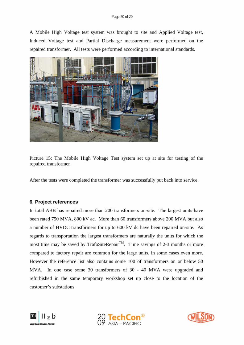
A Mobile High Voltage test system was brought to site and Applied Voltage test,
Induced Voltage test and Partial Discharge measurement were performed on the
repaired transformer. All tests were performed according to international standards.
Picture 15: The Mobile High Voltage Test system set up at site for testing of the repaired transformer
After the tests were completed the transformer was successfully put back into service.
6. Project references In total ABB has repaired more than 200 transformers on-site. The largest units have
been rated 750 MVA, 800 kV ac. More than 60 transformers above 200 MVA but also
a number of HVDC transformers for up to 600 kV dc have been repaired on-site. As
regards to transportation the largest transformers are naturally the units for which the
most time may be saved by TrafoSiteRepairTM. Time savings of 2-3 months or more
compared to factory repair are common for the large units, in some cases even more.
However the reference list also contains some 100 of transformers on or below 50
MVA. In one case some 30 transformers of 30 - 40 MVA were upgraded and
refurbished in the same temporary workshop set up close to the location of the
customer’s substations.

Page 21 of 21
7. Conclusions
The electrical market in most of the countries, not to say all, value more and more the
quality of the energy supplied to the end-users. One of the important challenges for
utilities is therefore to ensure no interruption in the delivery which means a high
availability and reliability of the different equipments installed in the networks.
Transformers being a key component among the electrical assets, ABB developed
dedicated solutions to help utilities and especially power producers managing their fleet
of equipment in a more efficient way. After several years of experience in many
countries ABB sees lots of value to combine condition assessment survey and
TrafoSiteRepairTM to help transformer owners reducing the downtime of their
equipment.
Condition Assessment provide relevant information to support informed decisions
needed to implement condition based maintenance and reduce repair time by better
planning the repair tasks and ordering of material.
TrafoSiteRepairTM based on a proven process and strong project management combined
with state-of-the-art technology and strict quality control allows reducing repair time by
several weeks or even months while ensuring a highly reliable repair.
Condition Assessment and TrafoSiteRepairTM helps utilities keeping a high standard of
energy delivery through improved availability of transformers.

Page 22 of 22
References:
1. W. Bartley, “Analysis of Transformer Failures”, Proceedings of the 67th Annual Int. Conf. of Doble Clients, Paper 8N, March 2000.
2. K.Carrander, L.Pettersson L.Melzer, N.Fantana, P.Lorin, “Methodology for life
assessment on power transformers”,TRAFOTECH-2002, Sixth International Conference on Transformers, 24-25 January 2002, Mumbai, India.
3. A. Fazlagic , M. Perkins, P.Lorin, “Transformer life assessment and advanced
diagnostics as tools in pro-active and advanced risk asset management“, Seventh European Electric Steelmaking conference, Venise, Italy, May 2002
4. R. Marek, JC. Duart and al, “Power Transformer Refurbishment: The Benefits of
Hybrid Insulation“, CIGRE Paris Session 2004
5. R. Albuquerque, J.C. Mendes, R. Marcondes, “On-Site Repair of an HVDC Transformer“, CIGRE Paris Session 2004
6. J.C. Mendes, R.A. Marcondes, J. Nakamura, “On-Site Tests on HV Power
Transformers”, CIGRE Paris Session 2004
7. P. Koestinger, T. Bruarøy, "Drying of power transformers in the field, applying the LFH-Technology in combination with oil reclamation", CIGRE Paris Session 2006
8. O. Berg, K. Herdlevar, M. Dahlund, K. Renström, A. Danielsen, U. Thiess,
“Experiences from on-site transformer oil reclaiming”, CIGRE Paris Conference Paper 12-103, 2002 Session
9. P. Koestinger, E. Aronsen, P. Boss, “Practical experience with the drying of power
transformers in the field, applying the Low Frequency Heating Technology (LFH) “, CIGRE Paris Session 2004.
10. J.C. Mendes, L. Eklund, P. Capuano, “Meet the challenges of tomorrow: Increase the
power of your transformer in record time“, Power-Gen Middle East, Bahrain 2008.
Page 23 of 23
____________________________________________________________________________________________ Pierre Lorin, M. Sc. Electrical & Mechanical. He Graduated Paris in 1992. From 1992 to 1996 he worked as a research engineer by the Swiss Federal Institute of Technology in Lausanne. He conducted researches for large utilities in Europe and North America on reliability and maintenance strategy for electrical overhead lines. He presented several publications on this topic during international conferences. From 1996 till today he has been with ABB Power Technologies - Transformers Service. He has been active in Research & Development, mainly involved in transformers reliability, diagnosis methods, on-line monitoring, and active noise control. He is now head of technology for transformers service activities. He is the author or co-author of several publications in this filed. ____________________________________________________________________________________________ Lars Eklund, M.Sc. in Electrical Engineering. He graduated from the Royal Institute of Technology in Stockholm 1974. After having started as development engineer for High Voltage Direct Current (HVDC) 1974 he had management positions in the field of design, R&D and HVDC project management for ASEA and ABB during more than 15 years. During the last 15 years he has had several senior management positions in the field of Power transmission systems and equipment within ABB. He is now the Product Manager for the On-Site Repair services of transformers. He is the author or co-author of several publications in the field of Power Transmission. ____________________________________________________________________________________________ ____________________________________________________________________________________________ Dr.-Ing. Peter Werle has studied Electrical Engineering at the University of Hannover, where he afterwards received his dr.-ing. degree at the Schering-Institute for High Voltage Technique and Engineering. Since 2003 he is with ABB AG, Transformer Service in Halle, Germany, where he is at the moment responsible for the departments condition assessment, quality management and high voltage testing. As technology manager for engineering solutions within the ABB transformer service group he is member of VDE, IEEE, DKE K 182 insulation liquids and CIGRÉ as liaison officer A2 - IEC TC 10. He is the author or co-author of more than 80 publications and owner of several patents in the above mentioned fields. ____________________________________________________________________________________________ __________________________________________________________________________________________ Dipl.-Ing. Ekkehard Zeitz studied High Voltage Engineering at Technische Hochschule Zittau and graduated as Dipl.-Ing. in 1988. He started his carrier as a test engineer at ABB AG in Halle, Germany and continued to work for ABB in Germany until 2006. He was then responsible for Service and Repairs and for Traction Transformers. He was also the Deputy Plant manager for the operation at ABB in Halle. Ekkehard Zeitz is since 2006 working for ABB Ltd in Bangkok, Thailand. Since 2008 he is the General Manager for the ABB Transformer plant in Bangkok and also responsibility for the Transformer Service business in South East Asia. ____________________________________________________________________________________________