Embed Size (px)
Citation preview
1
Transformer testing commissioning
and maintenance
Content :
1. Transformer types, categories, application and use
2. Classification of tests on transformer
3. Transformer polarity and vector group tests
2
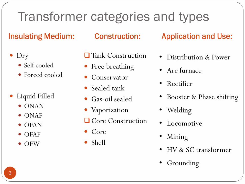
Transformer categories and types
Insulating Medium:
Dry
Self cooled
Forced cooled
Liquid Filled
ONAN
ONAF
OFAN
OFAF
OFW
Construction:
Tank Construction
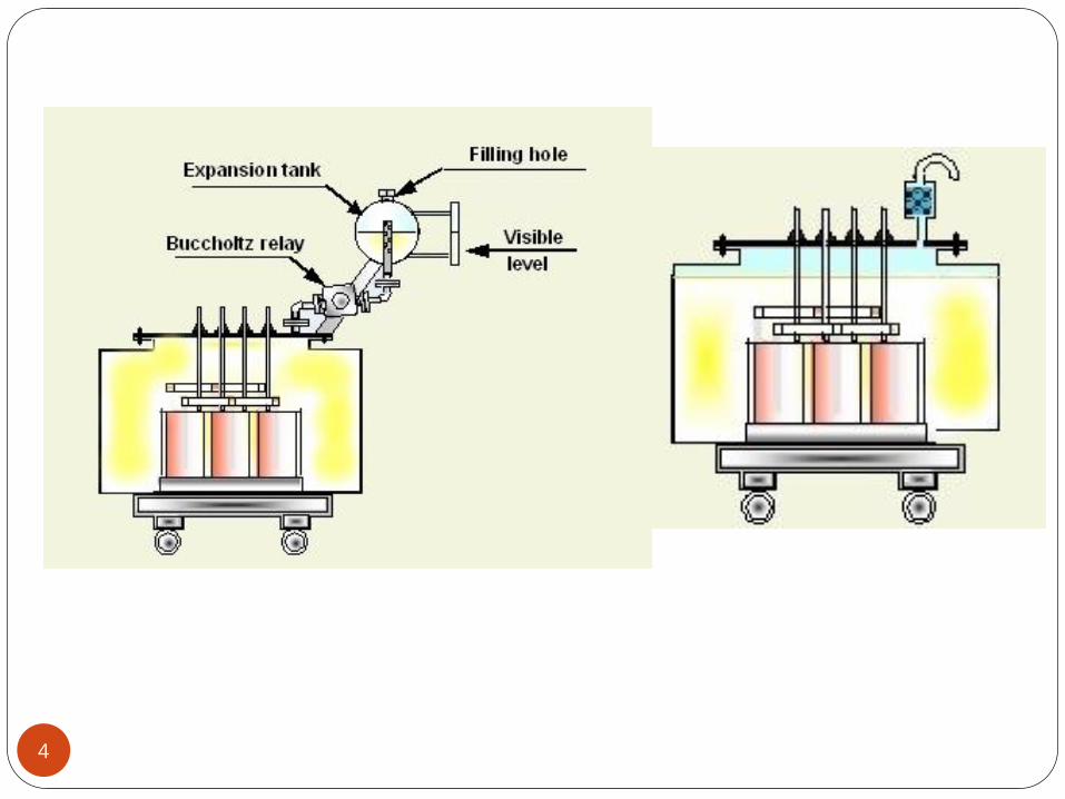
Free breathing
Conservator
Sealed tank
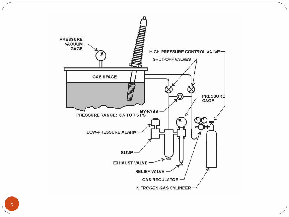
Gas-oil sealed
Vaporization
Core Construction
Core
Shell
3
Application and Use:
• Distribution & Power
• Arc furnace
• Rectifier
• Booster & Phase shifting
• Welding
• Locomotive
• Mining
• HV & SC transformer
• Grounding
4
5
Transformer Testing
DC testing of transformer involves testing of,
Solid Winding Insulation
Insulating Fluid
Solid winding insulation tests are not conclusive in
themselves but provide valuable information on winding
conditions, such as moisture content and carbonization.
DC tests are considered nondestructive.
6
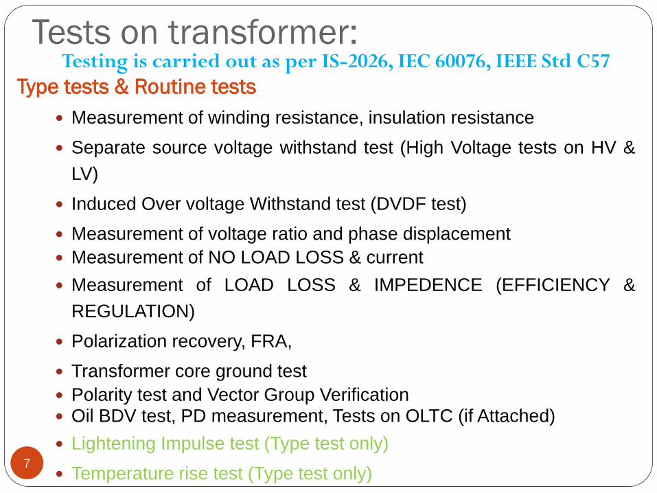
Tests on transformer:
Type tests & Routine tests
Measurement of winding resistance, insulation resistance
Separate source voltage withstand test (High Voltage tests on HV &
LV)
Induced Over voltage Withstand test (DVDF test)
Measurement of voltage ratio and phase displacement
Measurement of NO LOAD LOSS & current
Measurement of LOAD LOSS & IMPEDENCE (EFFICIENCY &
REGULATION)
Polarization recovery, FRA,
Transformer core ground test
Polarity test and Vector Group Verification Oil BDV test, PD measurement, Tests on OLTC (if Attached)
Lightening Impulse test (Type test only)
Temperature rise test (Type test only)7
Testing is carried out as per IS-2026, IEC 60076, IEEE Std C57
8
Special Tests
Additional Impulse test
Short circuit test
Measurement of zero Phase sequence Impedance
test
Measurement of acoustic noise level.
Measurement of harmonics of the no load current
Magnetic balance test
Capacitance and tanδ
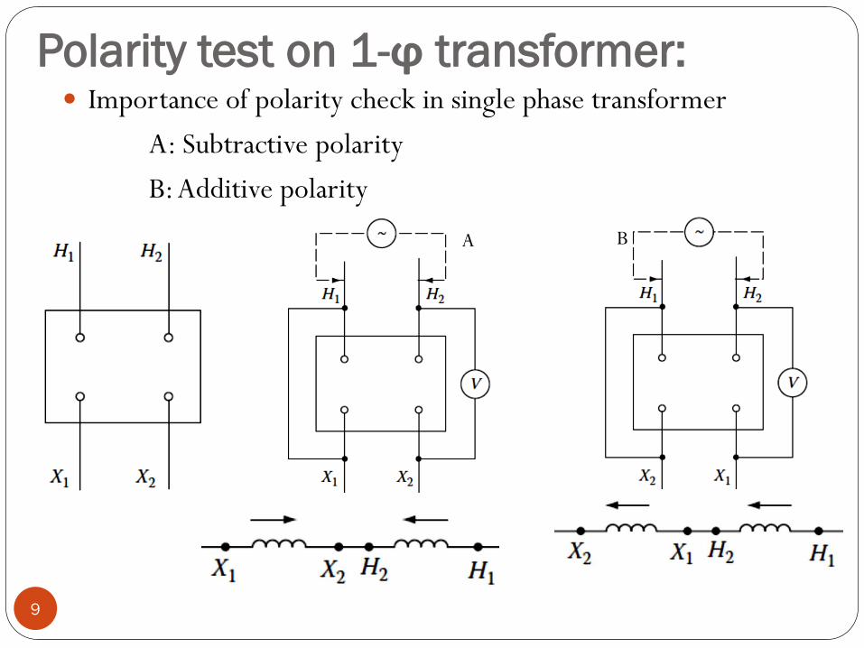
Polarity test on 1-ϕ transformer: Importance of polarity check in single phase transformer
A: Subtractive polarity
B: Additive polarity
9
A B
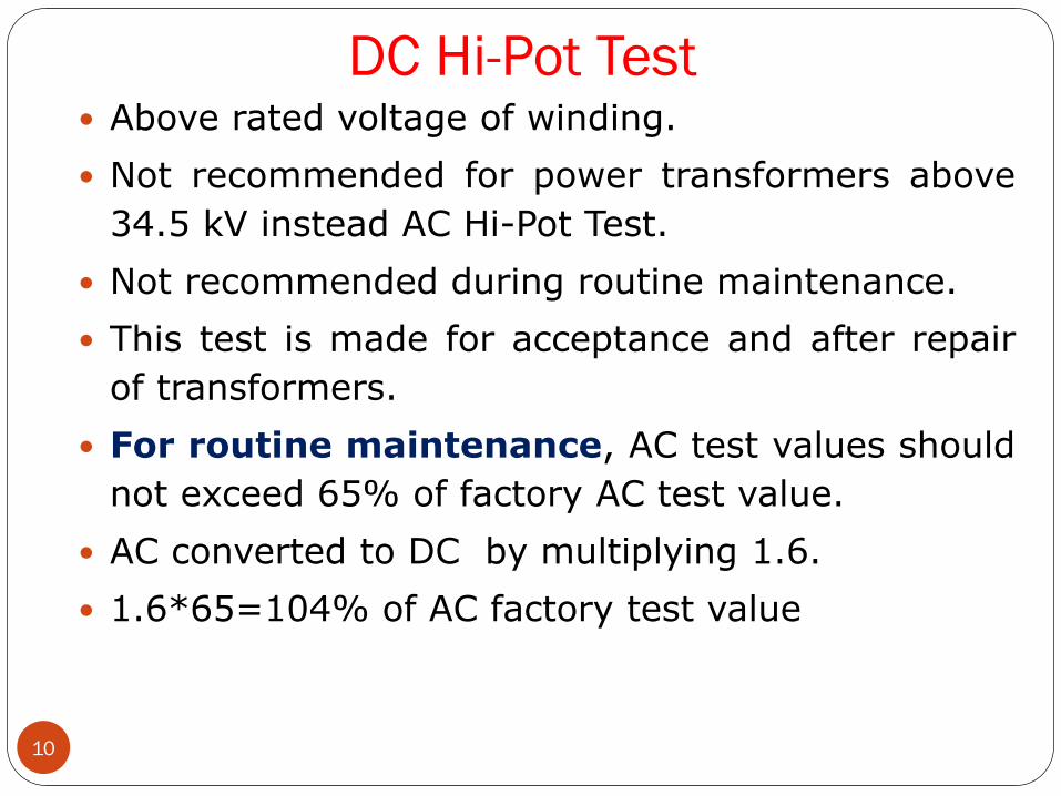
DC Hi-Pot Test
10
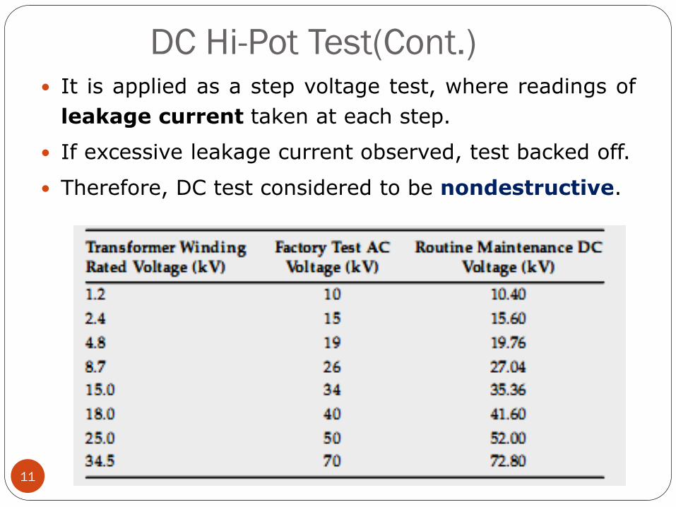
Above rated voltage of winding.
Not recommended for power transformers above
34.5 kV instead AC Hi-Pot Test.
Not recommended during routine maintenance.
This test is made for acceptance and after repair
of transformers.
For routine maintenance, AC test values should
not exceed 65% of factory AC test value.
AC converted to DC by multiplying 1.6.
1.6*65=104% of AC factory test value
DC Hi-Pot Test(Cont.)
11
It is applied as a step voltage test, where readings of
leakage current taken at each step.
If excessive leakage current observed, test backed off.
Therefore, DC test considered to be nondestructive.
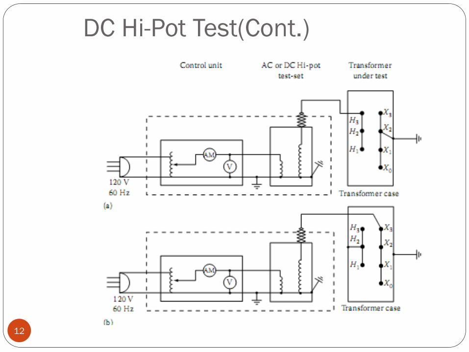
DC Hi-Pot Test(Cont.)
12
DC Hi-Pot Test (Cont.)
13
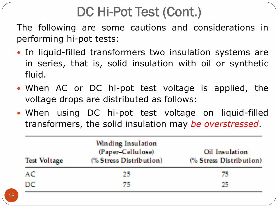
The following are some cautions and considerations in
performing hi-pot tests:
In liquid-filled transformers two insulation systems are
in series, that is, solid insulation with oil or synthetic
fluid.
When AC or DC hi-pot test voltage is applied, the
voltage drops are distributed as follows:
When using DC hi-pot test voltage on liquid-filled
transformers, the solid insulation may be overstressed.
Power Transformer Turns Ratio Test
14
The turns ratio test is an AC low voltage
test which determines the ratio of the high voltage
winding to all other windings at no-load.
The turns ratio test is performed on all taps of
every winding.
The Transformer Turns Ratio tester (TTR) is
device used to measure the turns ratio between
the windings (example shown below).
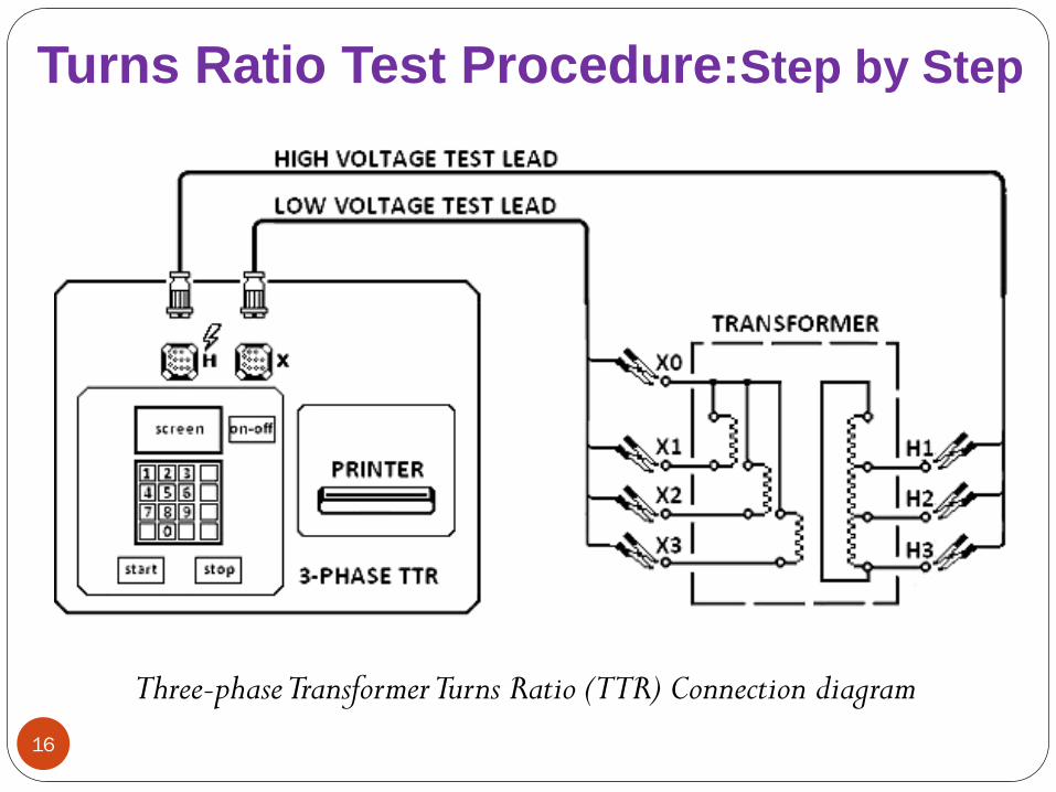
Voltage is applied on the H marked leads and
measured of the X marked lead by the test set.
Ratio measurements are conducted on all tap
positions and calculated by dividing the induced
voltage reading into the applied voltage value.
15
When ratio tests are being made on three-phase
transformers, the ratio is taken on one phase at a
time with a three-phase TTR until the ratio
measurements of all three phases are completed.
Measured ratio variations should be within 0.5%
of the nameplate markings.
16
Three-phase Transformer Turns Ratio (TTR) Connection diagram
Turns Ratio Test Procedure:Step by Step
17
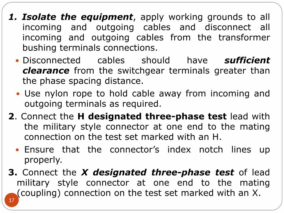
1. Isolate the equipment, apply working grounds to allincoming and outgoing cables and disconnect allincoming and outgoing cables from the transformerbushing terminals connections.
Disconnected cables should have sufficientclearance from the switchgear terminals greater thanthe phase spacing distance.
Use nylon rope to hold cable away from incoming andoutgoing terminals as required.
2. Connect the H designated three-phase test lead withthe military style connector at one end to the matingconnection on the test set marked with an H.
Ensure that the connector’s index notch lines upproperly.
3. Connect the X designated three-phase test of leadmilitary style connector at one end to the mating(coupling) connection on the test set marked with an X.

18
Ensure that the connector’s index notch lines up
properly.
4. Connect the H1,H2,H3 designated test lead to the
corresponding H1, H2,H3 transformer terminal/ bushing.
Connect the H0 test lead if H0 terminal/bushing is
present. (Refer to Figure 1)
5. Connect the X1,X2,X3 designated test leads to the
corresponding X1,X2,X3 transformer terminals/ bushings.
Connect the X0 test lead if X0 terminal/bushing is
present.
6. Perform turns ratio measurements for all tap positions.
7. Confirm that the measured ratios is within 0.5% of the
calculated ratios.
19
Vector group test on 3-ϕ transformer:
Vector groups in three phase transformer
Parallel connections of different vector groups
20
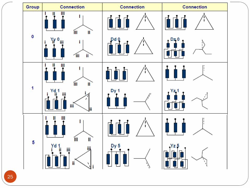
Determining the Connection Group
21
Depending on the type of the transformer, the
input and output windings of a multi-phase
transformer are connected either as star ( Y ) or
delta ( D ) or zigzag ( Z ).
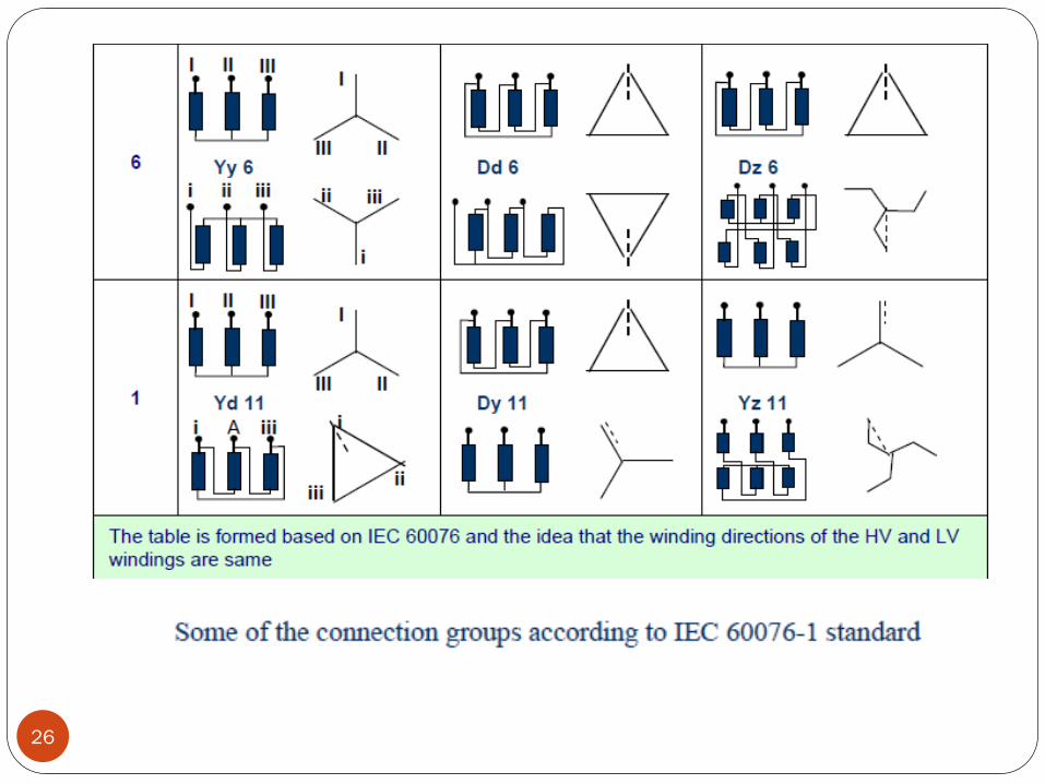
The phase angle between the high voltage and
the low voltage windings varies between 0◦ and
360◦ .
Representing as vectors, the HV winding is
represented as 12 (0) hour and the other
windings of the connection group are represented
by other numbers of the clock in reference to
the real or virtual point.
22
For example, in Dyn11 connection group, the HVwinding is delta and the LV winding is star andthere is a phase difference of 330◦ (11x30◦) betweentwo windings.
While the HV end shows 12 (0), the LV end shows11 o’clock (after 330◦).
Determining the connection group is valid only inthree phase transformers.
The high voltage winding is shown first (asreference) and the other windings follow it.
If the vector directions of the connection arecorrect, the bridge can be balanced.
Also, checking the connection group or polarity ispossible by using a voltmeter.
Direct current or alternating current can be used forthis check.
23
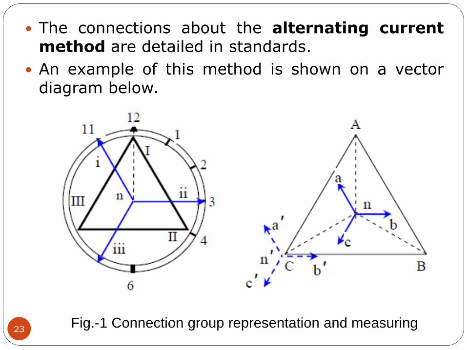
The connections about the alternating currentmethod are detailed in standards.
An example of this method is shown on a vectordiagram below.
Fig.-1 Connection group representation and measuring
24
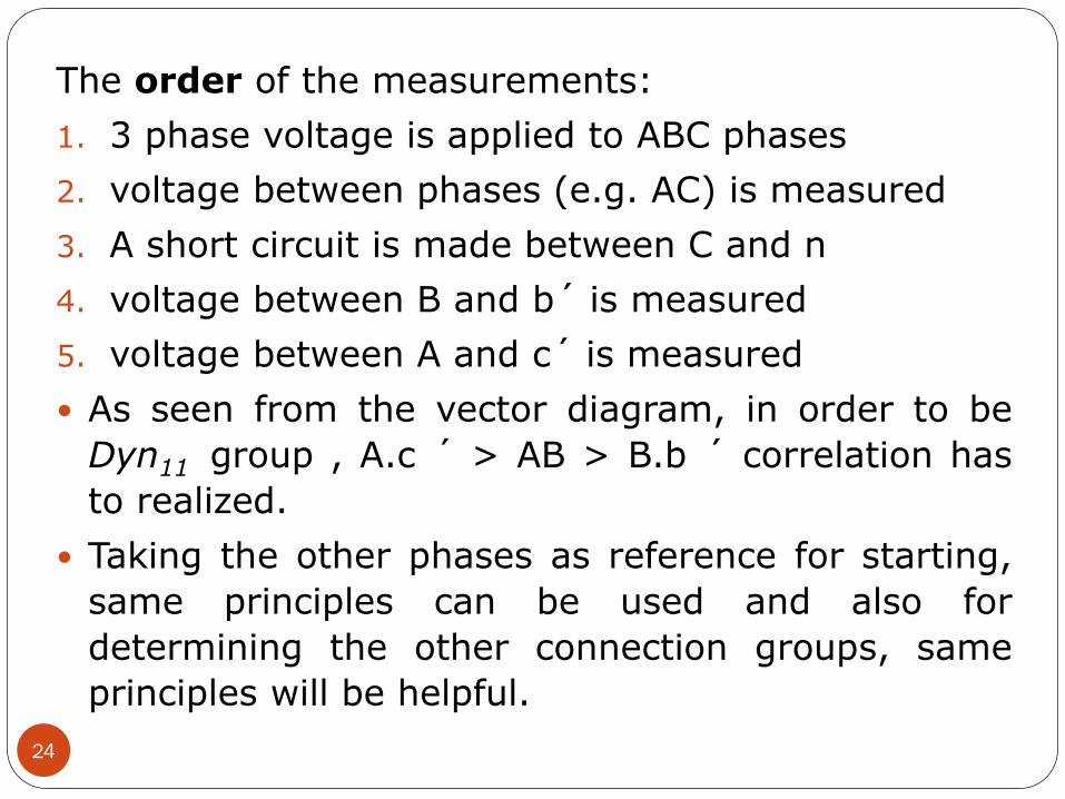
The order of the measurements:
1. 3 phase voltage is applied to ABC phases
2. voltage between phases (e.g. AC) is measured
3. A short circuit is made between C and n
4. voltage between B and b´ is measured
5. voltage between A and c´ is measured
As seen from the vector diagram, in order to be
Dyn11 group , A.c ´ > AB > B.b ´ correlation has
to realized.
Taking the other phases as reference for starting,
same principles can be used and also for
determining the other connection groups, same
principles will be helpful.
25
26
Measurement of
short-circuit impedance and load loss
27
The short-circuit loss and the short-circuit voltage show theperformance of the transformer.
These values are recorded and guaranteed to the customer andimportant for operational economy.
The short-circuit voltage is an important criteria especially
during parallel operations of the transformers.
The short-circuit loss is a data which is also used in the heattest.
Short-circuit voltage, is the voltage applied to the primary
winding and causes the rated current to flow in the windingcouples while one of the winding couples is short circuited.
The active loss measured during this, is called short-circuit loss.
28
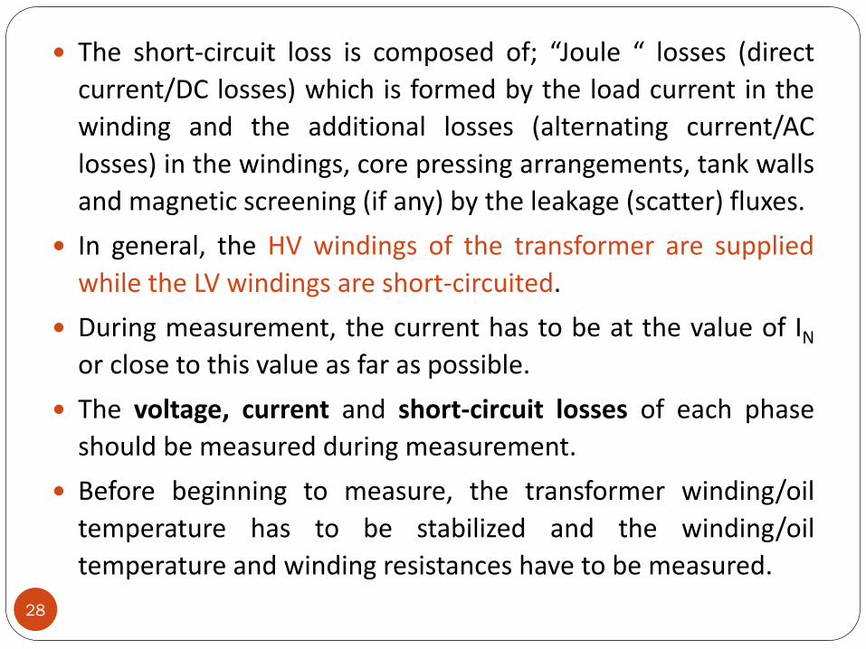
The short-circuit loss is composed of; “Joule “ losses (direct
current/DC losses) which is formed by the load current in the
winding and the additional losses (alternating current/AC
losses) in the windings, core pressing arrangements, tank walls
and magnetic screening (if any) by the leakage (scatter) fluxes.
In general, the HV windings of the transformer are supplied
while the LV windings are short-circuited.
During measurement, the current has to be at the value of IN
or close to this value as far as possible.
The voltage, current and short-circuit losses of each phase
should be measured during measurement.
Before beginning to measure, the transformer winding/oil
temperature has to be stabilized and the winding/oil
temperature and winding resistances have to be measured.
29
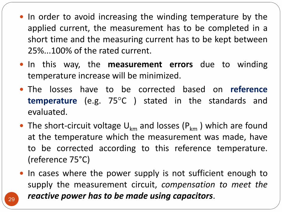
In order to avoid increasing the winding temperature by theapplied current, the measurement has to be completed in ashort time and the measuring current has to be kept between25%...100% of the rated current.
In this way, the measurement errors due to windingtemperature increase will be minimized.
The losses have to be corrected based on referencetemperature (e.g. 75°C ) stated in the standards andevaluated.
The short-circuit voltage Ukm and losses (Pkm ) which are foundat the temperature which the measurement was made, haveto be corrected according to this reference temperature.(reference 75°C)
In cases where the power supply is not sufficient enough tosupply the measurement circuit, compensation to meet thereactive power has to be made using capacitors.
30
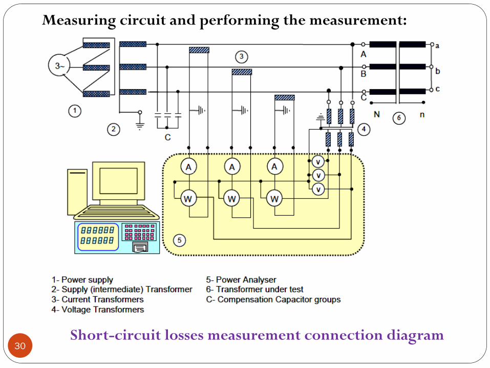
Measuring circuit and performing the measurement:
Short-circuit losses measurement connection diagram
31
The following insulation tests are performed in order to meet thetransformer insulation strength expectations.
Unless otherwise requested by the customer, the following testare performed in the following order (IEC 60076-3) :
1. Switching impulse test : To confirm the insulation of thetransformer terminals and windings to the earthed parts andother windings, and to confirm the insulation strength in thewindings and through the windings.
2. Lightning impulse test : to confirm the transformer insulationstrength in case of a lightning hitting the connection terminals.
3. Separate source AC withstand voltage test : to confirm theinsulation strength of the transformer line and neutralconnection terminals and the connected windings to theearthed parts and other windings.
32
4. Induced AC voltage test ( short duration ACSD and long
duration ACLD ) : to confirm the insulation strength of the
transformer connection terminals and the connected
windings to the earthed parts and other windings, both
between the phases and through the winding.
5. Partial discharge measurement : to confirm the “partial
discharge below a determined level” property of the
transformer insulation structure under operating conditions.
33
The aim of this test is to check the insulation strengthbetween the windings and earthed core, other windings,construction pieces and the tank, with foreseen testvoltage.
In this way, the insulation strength of the transformer istested against:
1. excessive voltages due to operational systeminstabilities,
2. malfunctions,
3. operational mistakes and transient events.
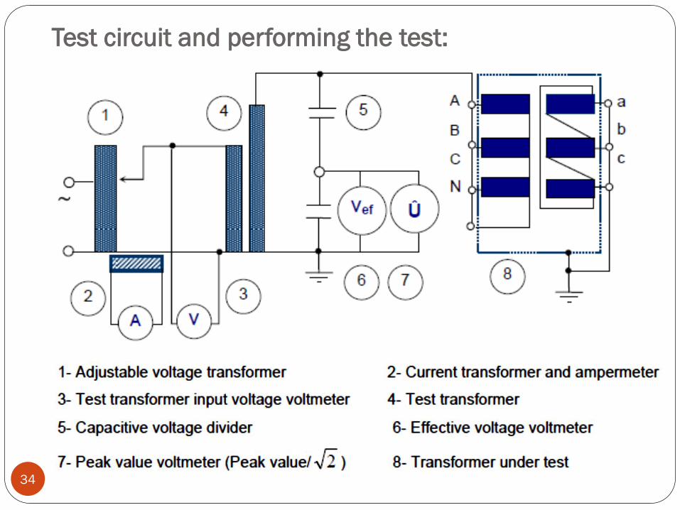
Test circuit and performing the test:
34
35
During the Separate source AC withstand voltage test, the
frequency of the test voltage should be equal to the
transformer’s rated frequency or should be not less than 80%
of this frequency.
In this way, 60 Hz transformers can also be tested at 50 Hz.
The shape of the voltage should be single phase and sinusoidal
as far as possible.
This test is applied to the star point (neutral point) of uniform
insulated windings and gradual (non-uniform) insulation
windings.
Every point of the winding which test voltage has been applied
is accepted to be tested with this voltage.
The insulation tests of the input terminals (phase inputs) of the
gradual insulation windings is completed during induced
voltage test. (Section 7).
36
The test voltage is measured with the help of a voltagedivider.
The test voltage should be read from voltmeter as peakvalue divided by √(2).
Test period is 1 minute. All the terminals of the windingunder test should be connected together and the voltageshould be applied here.
Meanwhile, the terminals of the non tested windingsshould be connected together as groups.
Non-tested windings, tank and the core should beearthed.
The secondary windings of bushing type currenttransformers should be connected together and earthed.
The current should be stable during test and no surgesshould occur.
37
The aim of this test is to check the insulation bothbetween phases and between turns of the windingsand also the insulation between the input terminals ofthe graded insulation windings and earth.
During test, normally the test voltage is applied to thelow voltage winding.
Meanwhile the other windings should be left open andearthed from a common point.
Since the test voltage will be much higher than thetransformer’s rated voltage, the test frequency shouldnot be less than twice the rated frequency value, inorder to avoid oversaturation of the transformer core.
38
The test voltage value is chosen according to the Um’value of the winding with highest operating voltage.
Other windings should be kept at a test level closest totheir own operation voltage.
The test voltage can either be measured on a voltagedivider connected to the HV terminal or on a voltagetransformer and voltmeter which have been set togetherwith this voltage divider at the LV side.
Another method is to measure the test voltage with apeak-value measuring instrument at the measuring-tapend of the capacitor type bushing (if any).
Test period which should not be less than 15 seconds, iscalculated according to the equation below:
120 seconds x ( Rated frequency / Test frequency )
39
The test is accepted to be successful if no surges,voltage collapses or extreme increases in the currenthas occurred.
As per the table at section 5, the induced voltage testsare classified as short duration or long duration andaccording to the operation voltage being less or morethan 72.5 kV, in IEC 60076-3 standard.
Different routine, type and special tests are performedaccordingly.
In transformers with the highest operation voltage lessthan 72.5 kV, partial-discharge measurement is notmandatory.
However in transformers bigger than 72.5 kV, partial-discharge measurement during induced voltage tests ismandatory.
40
(1) Uniform insulated windings :
The test connection of a transformer is the same asoperating connection.
Three phase, symmetrical voltage is applied to thetransformer under test.
Normally the test voltage is twice the rated voltage.
This voltage should not be more than the test voltage.
To be safe, the tap position of the transformer under testshould be appropriate.
The value of the test voltage (between phases andbetween phase and earth) is measured at the LV side onan accurate voltage transformer.
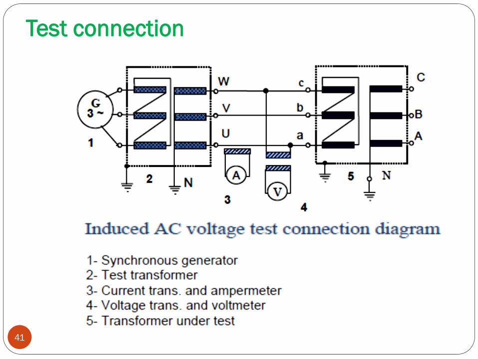
Test connection
41
42
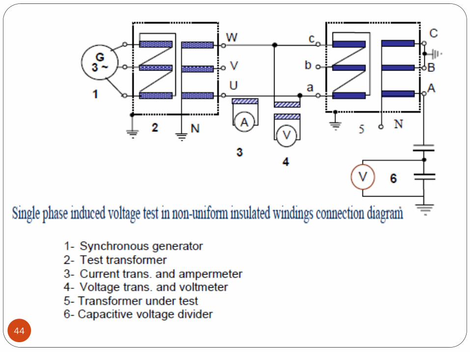
(2) Non-Uniform insulated windings :
There are two different methods for three phase
transformers:
1. Together with partial-discharge measurement, phase-earth
strength test.
2. Together with partial-discharge measurement, inter-phase
strength test while the star point is earthed. This test is
performed as explained in section a) above.
Only phase – earth test is applied to single phase
transformers. In three phase transformers, the test voltage is
applied to the phase terminals as single phase.
The test is repeated for each phase.
So, the foreseen test voltage is applied once to each HV
input.
43
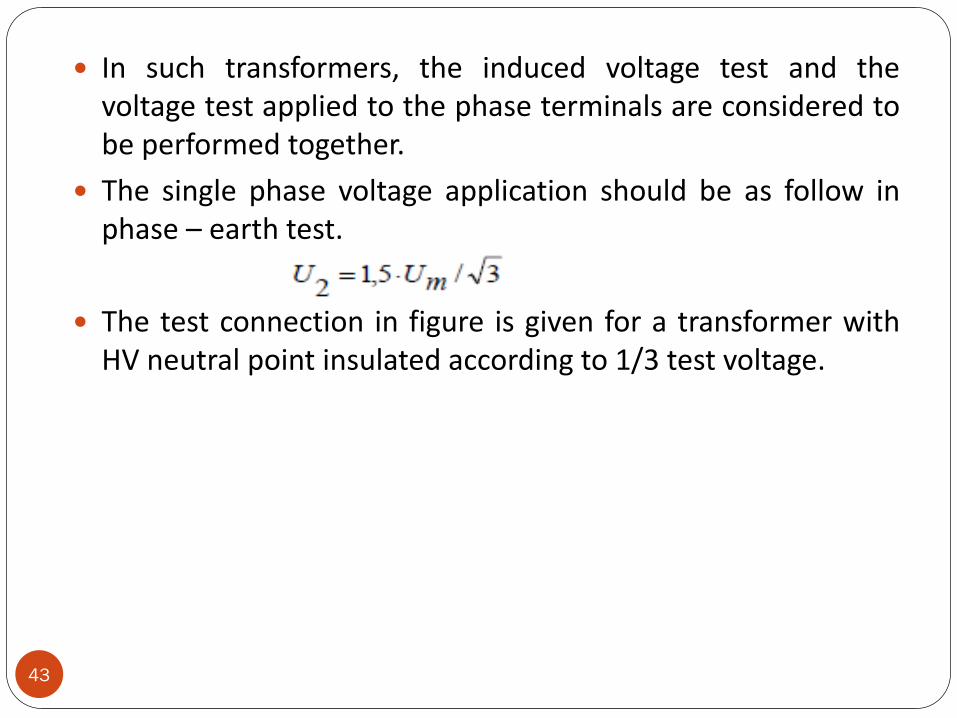
In such transformers, the induced voltage test and thevoltage test applied to the phase terminals are considered tobe performed together.
The single phase voltage application should be as follow inphase – earth test.
The test connection in figure is given for a transformer withHV neutral point insulated according to 1/3 test voltage.
44
45
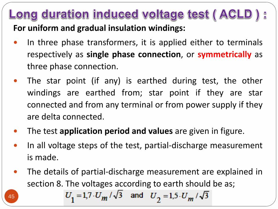
For uniform and gradual insulation windings:
In three phase transformers, it is applied either to terminals
respectively as single phase connection, or symmetrically as
three phase connection.
The star point (if any) is earthed during test, the other
windings are earthed from; star point if they are star
connected and from any terminal or from power supply if they
are delta connected.
The test application period and values are given in figure.
In all voltage steps of the test, partial-discharge measurement
is made.
The details of partial-discharge measurement are explained in
section 8. The voltages according to earth should be as;
46
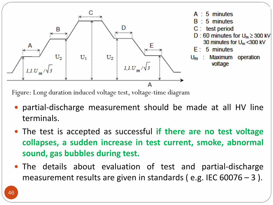
Figure: Long duration induced voltage test, voltage-time diagram
partial-discharge measurement should be made at all HV lineterminals.
The test is accepted as successful if there are no test voltagecollapses, a sudden increase in test current, smoke, abnormalsound, gas bubbles during test.
The details about evaluation of test and partial-dischargemeasurement results are given in standards ( e.g. IEC 60076 – 3 ).
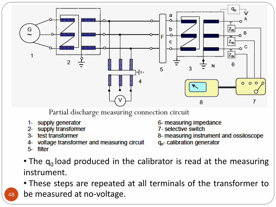
47
It aims to measure the partial discharges which may occur in
the transformer insulation structure during test.
Measuring circuit and application:
Partial-discharge measurement structure of a transformer and
related circuit in accordance with IEC 60270 is explained in the
next slide.
The measurement circuit in figure is formed according to
Bushing-tap method stated in standards.
Before starting to measure, complete measurement circuit
should be calibrated. For this, a calibrator (Calibration
generator) is necessary.
The calibrator produces a q0 load with a predefined value.
Calibrator is connected to the test material in parallel.
48
Partial discharge measuring connection circuit
• The q0 load produced in the calibrator is read at the measuringinstrument.• These steps are repeated at all terminals of the transformer tobe measured at no-voltage.
49
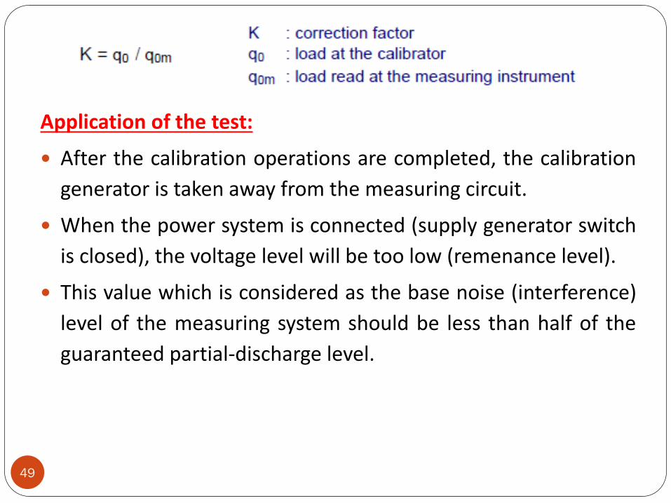
Application of the test:
After the calibration operations are completed, the calibration
generator is taken away from the measuring circuit.
When the power system is connected (supply generator switch
is closed), the voltage level will be too low (remenance level).
This value which is considered as the base noise (interference)
level of the measuring system should be less than half of the
guaranteed partial-discharge level.
50
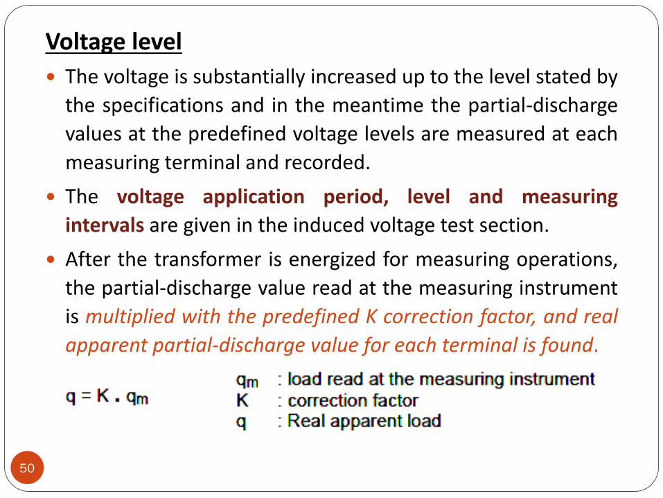
Voltage level
The voltage is substantially increased up to the level stated by
the specifications and in the meantime the partial-discharge
values at the predefined voltage levels are measured at each
measuring terminal and recorded.
The voltage application period, level and measuring
intervals are given in the induced voltage test section.
After the transformer is energized for measuring operations,
the partial-discharge value read at the measuring instrument
is multiplied with the predefined K correction factor, and real
apparent partial-discharge value for each terminal is found.
51
Evaluation:
The test is considered to be successful if the partial-discharge
value measured at the transformer’s measuring terminals is
lower than predefined values or values stated in the
standards and no increasing tendency is observed during test.
In addition to the measured partial-discharge level, the below
conditions should also be considered in transformers:
1. Partial-discharge start and cease voltages are above the
operating voltage.
2. Depending on the test period, partial-discharge level stays
approximately stable.
3. Increasing the test voltage causes almost no partial-
discharge level change.
Switching Impulse Voltage Test
52
The switching impulse test is applied to confirm thewithstand of the transformer’s insulation againstexcessive voltages occurring during switching.
During switching impulse voltage test, the insulationbetween windings and between winding and earth andwithstand between different terminals is checked.
The switching impulse voltage is generated inconventional impulse voltage generators at thelaboratories.
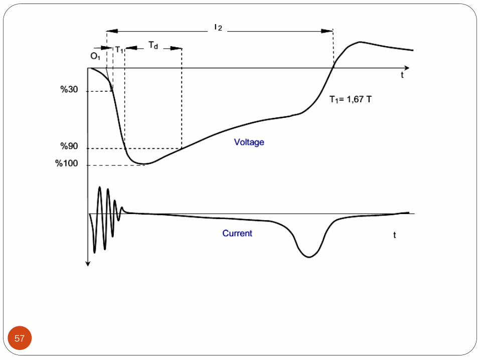
The polarity of the voltage is negative and the voltagewaveform should normally be T1/ Td/ T2 - 20/200/500μs /figure) according to IEC 60076-3.
53
Due to over-saturation of the core during switchingimpulse test, a few low amplitude, reverse polarity (e.g.positive) impulses are applied after each test impulse inorder to reset the transformer core to it’s startingcondition (demagnetized).
By this way, the next impulse voltage waveform is applied.
The tap position of the transformer during test isdetermined according to test conditions.
The on-off impulse voltages are applied to each highvoltage terminal sequentially.
Meanwhile, the neutral terminal is earthed.
The windings which are not under test are left open(earthed at one point).
This connection is similar to the induced voltage testconnection.
54
The voltage distribution on the winding is linear like theinduced voltage test and the voltage amplitudes at theun-impulsed windings are induced according to the turnratio.
Meanwhile, necessary arrangements should be made sincethe voltage between phases will be 1,5 times the phase-neutral voltage.
The test circuit connections of three phase transformersdepend on;
1. structure of the core (three or five legged),
2. the voltage level between phases and
3. the open or closed state of the delta winding (if any).
At first, a voltage with 50 % decreased value is used at thetests, then impulse voltages at full values and at numbersgiven in standards are used.
The peak value of the voltage is measured.
55
The change of the voltage waveform and winding currentare measured with a special measuring instrument andrecorded.
The negativities in the transformer during the test aredetermined by comparing the voltage and currentoscillograms.
The sudden collapses of the voltage (surges) andabnormal sounds show deformation of the insulation inthe transformer.
The deformation of the voltage waveform and increase innoise due to magnetic saturation of the core should notbe considered as fault.
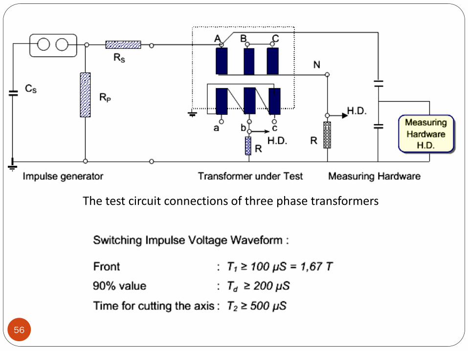
56
The test circuit connections of three phase transformers
57
58
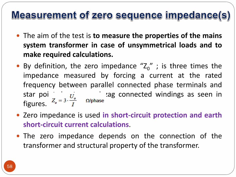
The aim of the test is to measure the properties of the mainssystem transformer in case of unsymmetrical loads and tomake required calculations.
By definition, the zero impedance “Z0” ; is three times theimpedance measured by forcing a current at the ratedfrequency between parallel connected phase terminals andstar point, in star or zigzag connected windings as seen infigures.
Zero impedance is used in short-circuit protection and earthshort-circuit current calculations.
The zero impedance depends on the connection of thetransformer and structural property of the transformer.
59
The zero impedance consists of R0 real and X0 imaginary parts.Here, since R0 << X0, R0 is negligible.
In this case, the zero impedance equals zero reactance.
Zero impedance can only be measured in windings with starpoint taken out.
Measurement is made at the rated tap position and with theactive part assembled in the tank.
The zero impedance of delta connected windings andwindings with the star point not possible to take out, isinfinite in magnitude.
If the other winding of the transformer is delta connected or ifthere is a delta connected balance winding, the star point ofthe star (or zig-zag) connected winding can be loaded withmaximum rated current during Z0 impedance measurement.
60
Meanwhile, it is seen that the U0 test voltage is 15% to 27% ofthe rated phase-neutral voltage of the transformer.
In cases where there is no counter magnetic current, forexample in start-star connected, three legged transformerswith no balancing winding, this test current should bemaximum 0,3xIN in order to avoid excessive heating of theconstructive parts.
In transformers with both windings star connected and thestar points taken out, there are two different zeroimpedances.
61
(1) No-load zero impedance Z00
While one of the star connected windings is measured,the ends of the other winding is kept open. See Figure.
(2) Short-circuit zero impedance Z0K
While one of the star connected windings is measured,the ends of the other winding and the star point isshort-circuited. See Figure.
62
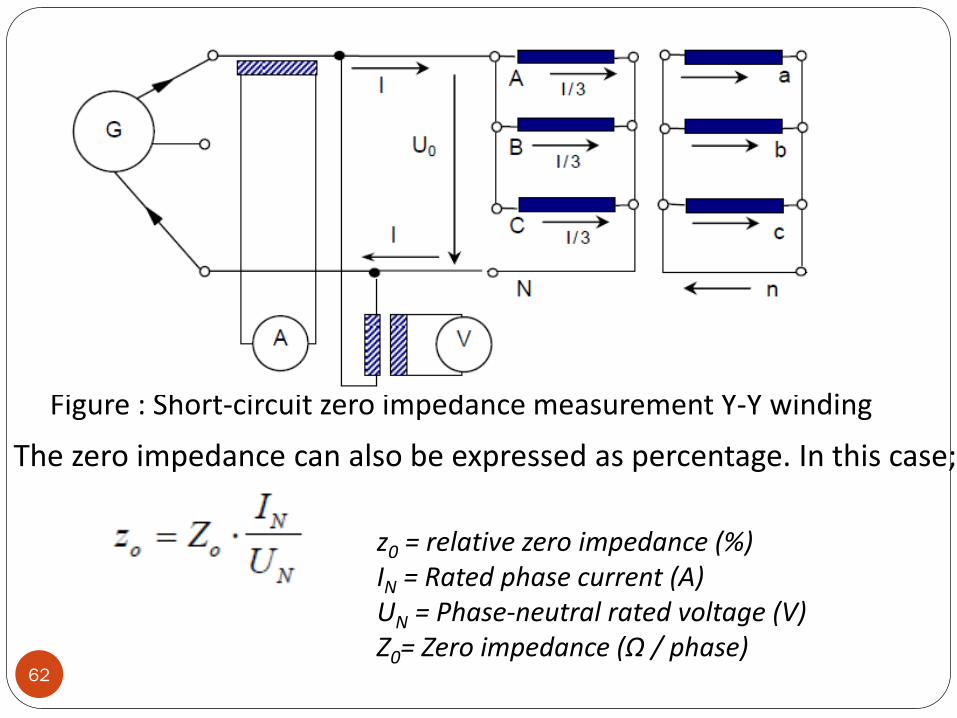
Figure : Short-circuit zero impedance measurement Y-Y winding
The zero impedance can also be expressed as percentage. In this case;
z0 = relative zero impedance (%) IN = Rated phase current (A) UN = Phase-neutral rated voltage (V) Z0= Zero impedance (Ω / phase)
63
Aim of measurement:
To confirm that the sound (noise) level of the transformerand related equipments meet the customer’s demandsand/or standards.
Explanations about transformer noise is given inIEC 60076-10.
Main causes of a transformer noise is explained below:
1. Core noise: caused by the magnetic forces betweenmagnetositriction and core sheet steel.
2. Noise of the transformer’s load (current): caused by currentpassing in the windings, and by electromagnetic forcesformed at the magnetic screenings at the tank walls.
3. Noise of the cooling equipments: caused by fans and pumpsof the cooling system.
64
An effective and important noise source is the core of thetransformer.
The noise of the core depends on the magnetic property ofthe core material (sheet steel) and flux density.
The sound frequency is low (twice the rated frequency).
The magnetic forces formed in the core cause vibration andnoise.
The load noise occurs only on the loaded transformers andis added to the no-load (core noise ).
This noise is caused by the electromagnetic forces due toleakage fields.
The source of the noise are tank walls, magnetic screeningsand vibrations of the windings.
The noises caused by the core and windings are mainly inthe 100-600 Hz frequency band.
65
The frequency range of the noise ( aerodynamic/air andmotor/bearing noise ) caused by cooling fans is generallywide.
The factors effecting the total fan noise are; speed, bladestructure, number of fans and arrangements of the radiators.
The pump noise is not effective when the fans are workingand its frequency is low.
During noise measurements below precautions are veryimportant to ensure the accuracy of the results :
1. The transformer should be placed in a room with minimumecho properties.
It should be placed on a base with no direct vibrations orshould be placed on wheels.
All mechanical components/equipments on the transformershould be fixed to avoid vibration with the transformer.
66
2. During measurement, the transformer should be supplied at rated voltage and rated frequency.
Before starting the measurement procedure, the background noise level of the measurement room should bedetermined.
If there is more than 8 dB (A) difference between background noise level and transformer noise level, nocorrection of the transformer’s noise level is required.
If the difference is between 3 dB (A) and 8 dB (A), acorrection is required according to standards.
If the difference between the back ground noise level andtransformer noise level is less than 3 dB, a measurement isnot necessary.
Measurement of harmonics of the no-load current
67
They are measured to use whenever necessary during theoperating of the transformer.
In general, the ratio of harmonic currents in the ratedcurrent is less than 1%.
The amplitude of the harmonics component depends onthe property of transformer’s core material, inductiondegree, core design, connection of windings andimpedance of the transformer’s supply circuit.
The measurement of current and voltage harmonics aredone during the no-load losses and currents measurement(section 4) by the same test connection.
The measurement circuit connection diagram is given infigure
68
The supply voltage of the transformer at the test laboratoryshould be sinusoidal.
Because of the possible defects in the no-load current, thesupply voltage may deviate from sinus wave.
To avoid this, the test generator and the connections of the testtransformer should be appropriate and should make sure thatthey are at the linear operation area of their magneticcharacteristics.
The measurement currents and voltages are connected to theanalyzer through measurement current and voltagetransformers.
Because of this, the operation areas of the measurementtransformers should also be linear.
By this way, the measurement transformers will not produceharmonics.
The measurements are repeated for each of the three phases.
69
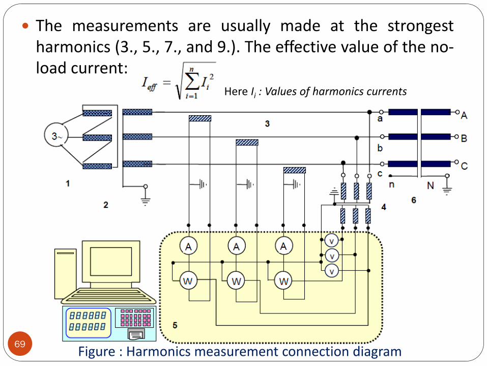
The measurements are usually made at the strongestharmonics (3., 5., 7., and 9.). The effective value of the no-load current:
Here Ii : Values of harmonics currents
Figure : Harmonics measurement connection diagram
70
1- Power supply
2- Supply (intermediate) Transformer
3- Measurement Current Transformers
4- Measurement Voltage Transformers
5- Harmonics Analyzer / Power Analyzer
6- transformer under Test
DISSOLVED GAS ANALYSIS (DGA) (Latest trends in transformer health monitoring)
The DGA is a basically a laboratory test using an oil sampletaken from a transformer.
The oil sample is subjected to a vacuum to remove thecombustible (explosive) gases.
These gases are then passes through a gas chromatographand each gas is then extracted and analyzed for type andquality.
The quantity of each gas is given in part per million( ppm ) or percent of the total gas present.
The analysis of each gas present provides a useful tool indetermining the condition of transformer.
72
The interpretation of the analysis has not yet beenperfected to an exact science and is therefore to anexact(precise) science and is therefore subjected tointerpretation.
The DGA is the most informative method of detectingcombustible gases.
Although this is a laboratory method ,it provides theearliest possible detection of any abnormal conditions inthe transformer.