Embed Size (px)
Citation preview

1
Název projektu: Automatizace výrobních procesů ve strojírenství a řemeslech
Registrační číslo: CZ.1.07/1.1.30/01.0038
Příjemce: SPŠ strojnická a SOŠ profesora Švejcara Plzeň, Klatovská 109
Tento projekt je spolufinancován Evropskou unií a státním rozpočtem České republiky
Produkt:
Zavádění cizojazyčné terminologie do výuky odborných
předmětů a do laboratorních cvičení
Transformers
Návod v anglickém jazyce
Číslo tématu: 6b
Monitorovací indikátor: 06.43.10

2
INSTRUCTIONS FOR TOPIC: 6b
Created in school year: 2012/2013
Branch: 26-41-M/01 Electrical Engineering - Mechatronics
Subject: Measurement and diagnostics
Year: 3.
Prepared by: Ing. Milan Nechanický; translated by: Bc. Veronika Mádlová
Transformers
Introduction
Transformer is an electrical non-rotating machine
It works on a principle of electromagnetic induction (Faraday's law of
induction)
It converts AC voltage to AC voltage of different intensity (or the same
intensity in case of isolation transformer)
Transformation ratio p
Single Phase Transformer
Basic parts of a transformer:
- magnetic circuit made of transformer sheets
- windings (primary and secondary)
1
2
2
1
2
1
I
I
N
N
U
Up

3
Unloaded Transformer
Magnetic flux changes sinusoidally in a time period and its course is 90° delayed
after the voltage U1.
Magnetic fluxes of an unloaded transformer are real, caused by current
I1
Phasor Diagram of Ideal Unloaded Transformer
The resistence of winding, leakage flows and the losses of iron are neglected.
Basic Relations of Ideal Transformer:

4
Phasor Diagram of Real Unloaded Transformer
Formula of Effective Value of Induced Voltage:
R1 = R2 = 0 021
dt
dNU
11
dt
dNU
22
2
1
2
1
N
N
U
U
1
2
2
12211
N
N
I
IIUIU

5
Ideal Loaded Transformer:
Magnetic fluxes of a loaded transformer are fictive fluxes. The other
fluxes are real.
dt
dNU i
tj
me
tj
mi eNjU fNU mi 2max
mmi
ief fNfNU
U
44,42
2
2
max
6
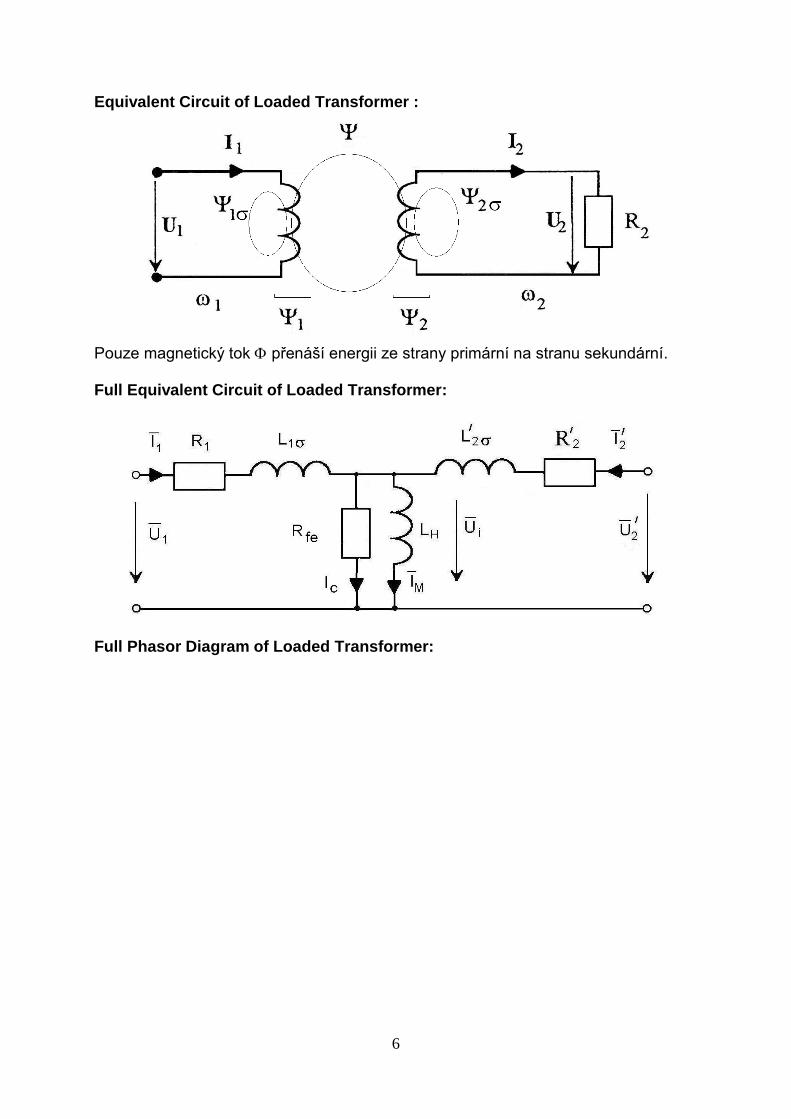
Equivalent Circuit of Loaded Transformer :
Pouze magnetický tok přenáší energii ze strany primární na stranu sekundární. Full Equivalent Circuit of Loaded Transformer:
Full Phasor Diagram of Loaded Transformer:

7
Simplified Equivalent Circuit of Loaded Transformer :

8
At large transformers the values R1, R2, X1, X2 are low and the values X12 a Rfe
high.
Therefore it is possible to use following simplification:
X1K = X1σ + X2σ R1K = R1 + R2

9
The resistence of windings, iron losses and leakage inductance are neglected.
The resistence of winding and iron losses are neglected.

10
Iron losses are neglected in this case.

11
The resistance of windings and the leakage inductance are neglected.
Leakage inductance is neglected.

12
Transformer in Short Circuit
Iron losses are neglected in this case.
Three-phase Transformer:

13
Possible Winding Circuits of Three-phase Transformer- Hour Angle
Dd: 0 1 2 4 6 8 10
Dy: 5 7 11
Dz: 0 2 4 6 8 10
Yd: 1 5 7 11
Yy: 0 6
Yz: 1 5 7 11
Examples of Winding Circuits of Three-phase Transformer – Yy6

14
Examples of Winding Circuits of Three-phase Transformer – Yy0
Examples of Winding Circuits of Three-phase Transformer – Dd0
Yy0 (0o)
Dd0 (0o)

15
Examples of Winding Circuits of Three-phase Transformer – Dy1
Examples of Winding Circuits of Three-phase Transformer – Dy5
Dy1 (30o)

16
Examples of Winding Circuits of Three-phase Transformer – Dy7
Secondary Winding Connected to Angled Star
The secondary winding is divided into two stages and each one happens on a
different core of the transformer.
The advantage is that the phase voltage on the secondary side stays the
same even if the transformer is asymmetrically loaded (that means there is
current in a zero conductor).
Dy5 (150o)
Dy7 (210o)

17
Zdroje:
poznámky z předmětu Základy teoretické elektrotechniky - 2. semestr při ZČU Plzeň
BLAHOVEC, A., Elektrotechnika I, Praha: Informatorium s.r.o., 2002. ISBN 978-80-
7333-043-1.
BLAHOVEC, A., Elektrotechnika II, Praha: Informatorium s.r.o., 2002. ISBN 978-80-
7333-044-6.

18
Transformátory - Transformers - slovníček odborných termínů
Vocabulary Slovníček
transformátor transformer
napětí voltage
vinutí winding
nezatížený transformátor unloaded transformer
zatížený transformátor loaded transformer
proud current
magnetický tok magnetic flux
rozptylová indukčnost leakage inductance
elektromagnetická indukce electromagnetic induction
odpor resistance
zapojení circuit


![f(0O]. J}tL toJ](https://img.pdfslide.net/doc/110x75/61980b8063c8765f6043bec1/f0o-jtl-toj.jpg)


![0o+==o[Berbagai Kumpulan Makalah]+==o0o==](https://img.pdfslide.net/doc/110x75/55cf9730550346d033902a14/0ooberbagai-kumpulan-makalaho0o.jpg)