Embed Size (px)
Citation preview
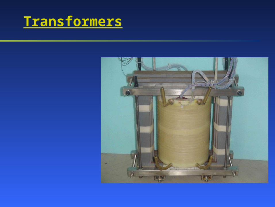
Transformers
Some history
The second generation of power distribution systems (what we are still using) was proposed by Tesla few years later. His idea was to generate AC power of any convenient voltage, step up the voltage for transmission (higher voltage implies lower current and, thus, lower losses), transmit AC power with small losses, and finally step down its voltage for consumption. Since power loss is proportional to the square of the current transmitted, raising the voltage, say, by the factor of 10 would decrease the current by the same factor (to deliver the same amount of energy) and, therefore, reduce losses by factor of 100.
Historically, the first electrical power distribution system developed by Edison in 1880s was transmitting DC. It was designed for low voltages (safety and difficulties in voltage conversion); therefore, high currents were needed to be generated and transmitted to deliver necessary power. This system suffered significant energy losses!
The step up and step down voltage conversion was based on the use of transformers.
Preliminary considerations
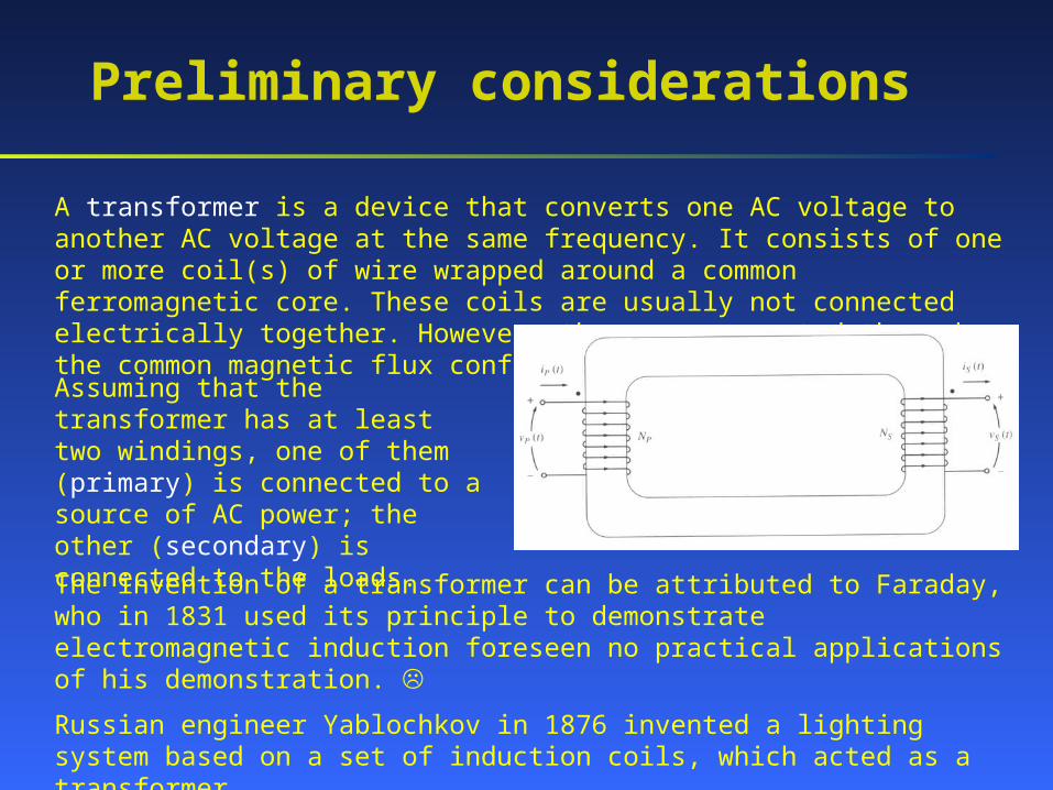
A transformer is a device that converts one AC voltage to another AC voltage at the same frequency. It consists of one or more coil(s) of wire wrapped around a common ferromagnetic core. These coils are usually not connected electrically together. However, they are connected through the common magnetic flux confined to the core.
Assuming that the transformer has at least two windings, one of them (primary) is connected to a source of AC power; the other (secondary) is connected to the loads.
The invention of a transformer can be attributed to Faraday, who in 1831 used its principle to demonstrate electromagnetic induction foreseen no practical applications of his demonstration.
Russian engineer Yablochkov in 1876 invented a lighting system based on a set of induction coils, which acted as a transformer.
More history
Gaulard and Gibbs first exhibited a device with an open iron core called a 'secondary generator' in London in 1882 and then sold the idea to a company Westinghouse. They also exhibited their invention in Turin in 1884, where it was adopted for an electric lighting system.
In 1885, William Stanley, an engineer for Westinghouse, built the first commercial transformer after George Westinghouse had bought Gaulard and Gibbs' patents. The core was made from interlocking E-shaped iron plates. This design was first used commercially in 1886.
Hungarian engineers Zipernowsky, Bláthy and Déri created the efficient "ZBD" closed-core model in 1885 based on the design by Gaulard and Gibbs. Their patent application made the first use of the word "transformer".
Another Russian engineer Dolivo-Dobrovolsky developed the first three-phase transformer in 1889.
Finally, in 1891 Nikola Tesla invented the Tesla coil, an air-cored, dual-tuned resonant transformer for generating very high voltages at high frequency.
Types and construction
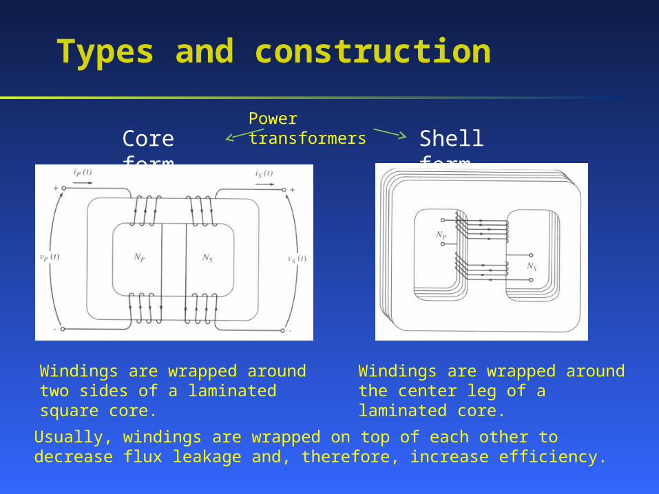
Core form Shell formPower transformers
Windings are wrapped around two sides of a laminated square core.
Windings are wrapped around the center leg of a laminated core.
Usually, windings are wrapped on top of each other to decrease flux leakage and, therefore, increase efficiency.
Types and construction
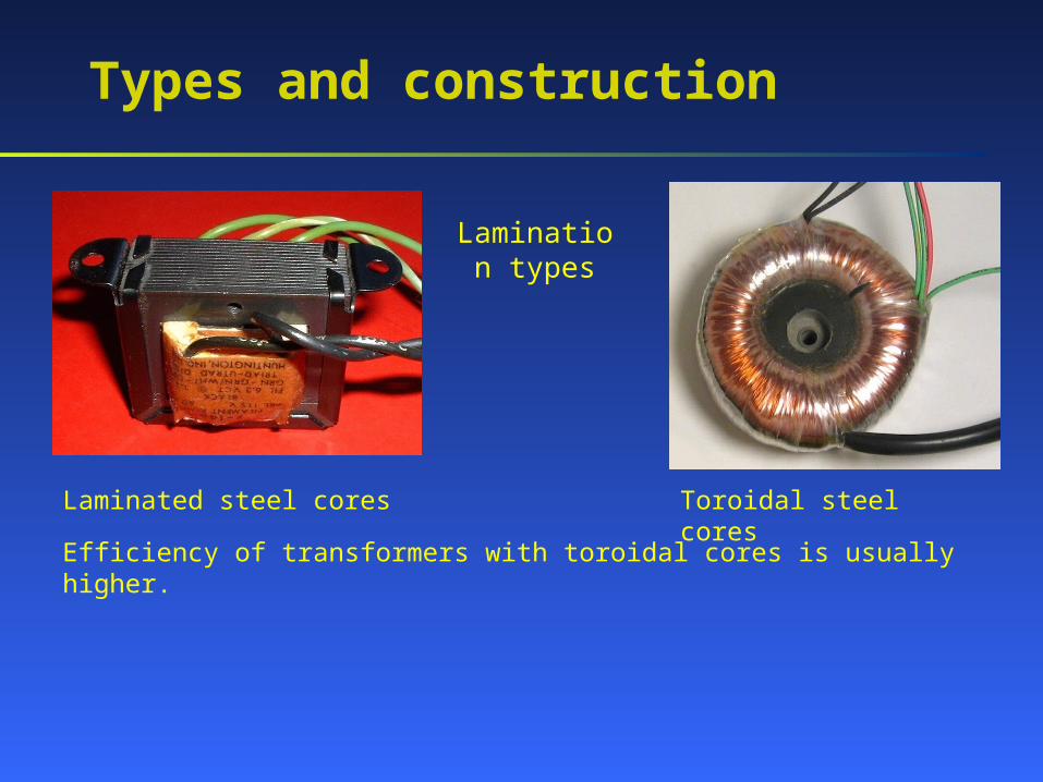
Lamination types
Laminated steel cores Toroidal steel cores
Efficiency of transformers with toroidal cores is usually higher.
Types and construction
A power transformer connected to the output of a generator and used to step its voltage up to the transmission level (110 kV and higher) is called a unit transformer.
A transformer used at a substation to step the voltage from the transmission level down to the distribution level (2.3 … 34.5 kV) is called a substation transformer.
A transformer converting the distribution voltage down to the final level (110 V, 220 V, etc.) is called a distribution transformer.
In addition to power transformers, other types of transformers are used.
Power transformers used in power distribution systems are sometimes referred as follows:
Ideal transformer
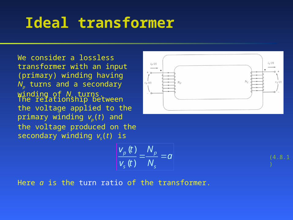
We consider a lossless transformer with an input (primary) winding having Np turns and a secondary winding of Ns turns.
The relationship between the voltage applied to the primary winding vp(t) and the voltage produced on the secondary winding vs(t) is
( )
( )p p
s s
v t Na
v t N (4.8.1)
Here a is the turn ratio of the transformer.
Ideal transformer
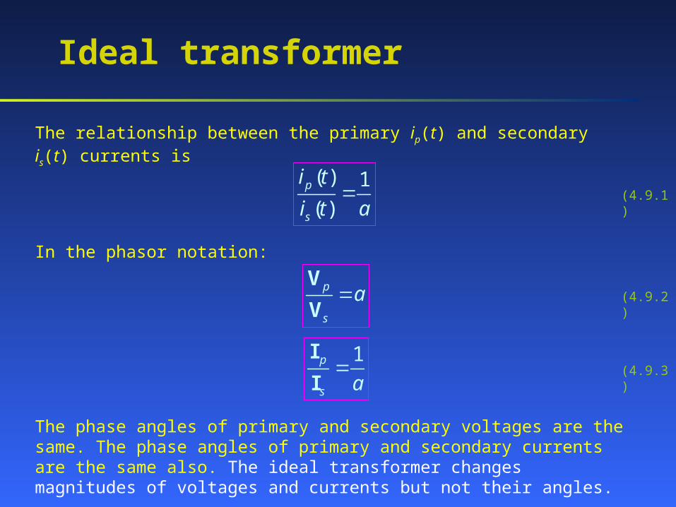
The relationship between the primary ip(t) and secondary is(t) currents is
( ) 1
( )p
s
i t
i t a (4.9.1)
In the phasor notation:
p
s
aV
V
1p
s a
I
I
(4.9.2)
(4.9.3)
The phase angles of primary and secondary voltages are the same. The phase angles of primary and secondary currents are the same also. The ideal transformer changes magnitudes of voltages and currents but not their angles.
Ideal transformer
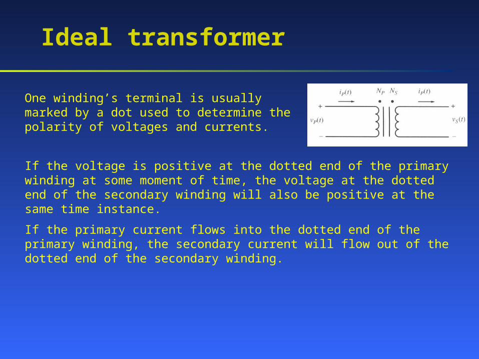
One winding’s terminal is usually marked by a dot used to determine the polarity of voltages and currents.
If the voltage is positive at the dotted end of the primary winding at some moment of time, the voltage at the dotted end of the secondary winding will also be positive at the same time instance.
If the primary current flows into the dotted end of the primary winding, the secondary current will flow out of the dotted end of the secondary winding.
Power in an ideal transformer
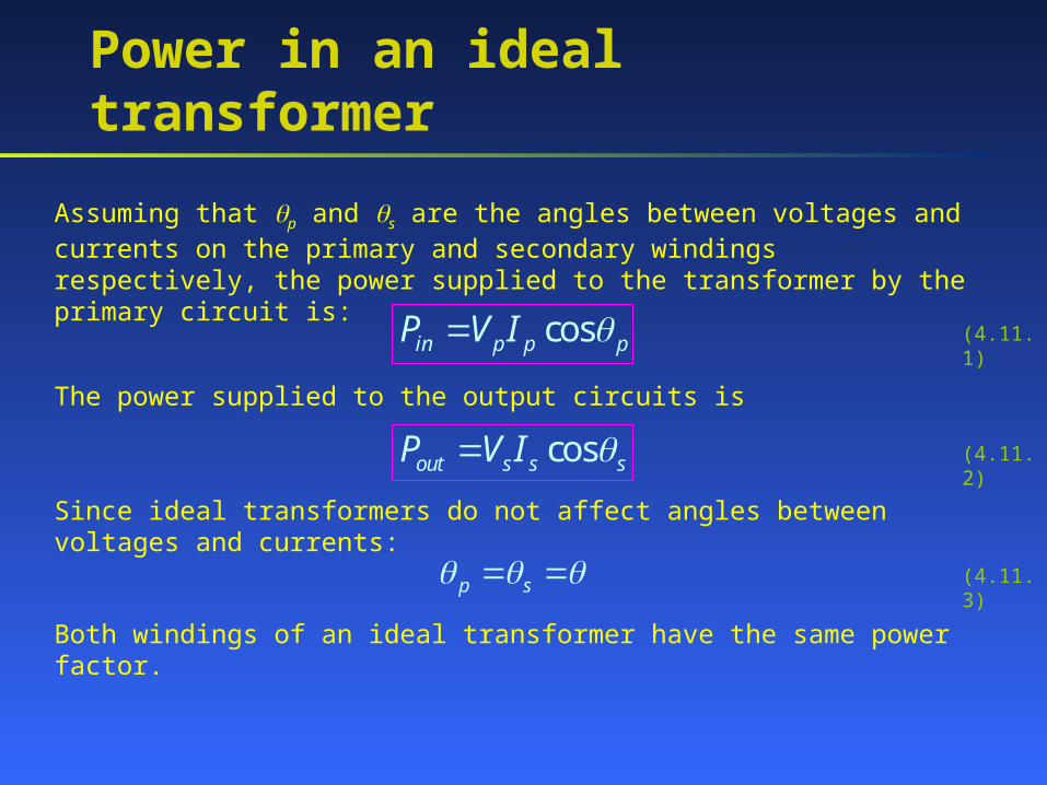
Assuming that p and s are the angles between voltages and currents on the primary and secondary windings respectively, the power supplied to the transformer by the primary circuit is:
cosin p p pP V I (4.11.1)
The power supplied to the output circuits is
cosout s s sP V I (4.11.2)
Since ideal transformers do not affect angles between voltages and currents:
p s (4.11.3)
Both windings of an ideal transformer have the same power factor.
Power in an ideal transformer
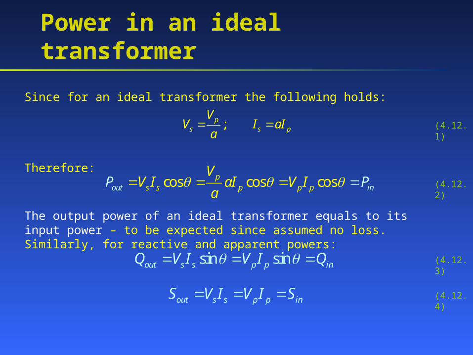
Since for an ideal transformer the following holds:
;ps s p
VV I aI
a
Therefore:cos cos cosout i
ps s p p p n
VV I aIP V I
aP
The output power of an ideal transformer equals to its input power – to be expected since assumed no loss. Similarly, for reactive and apparent powers:
sin sinout s s p p inQ V I V I Q
out s s p p inS V I V I S
(4.12.1)
(4.12.2)
(4.12.3)
(4.12.4)
Impedance transformation
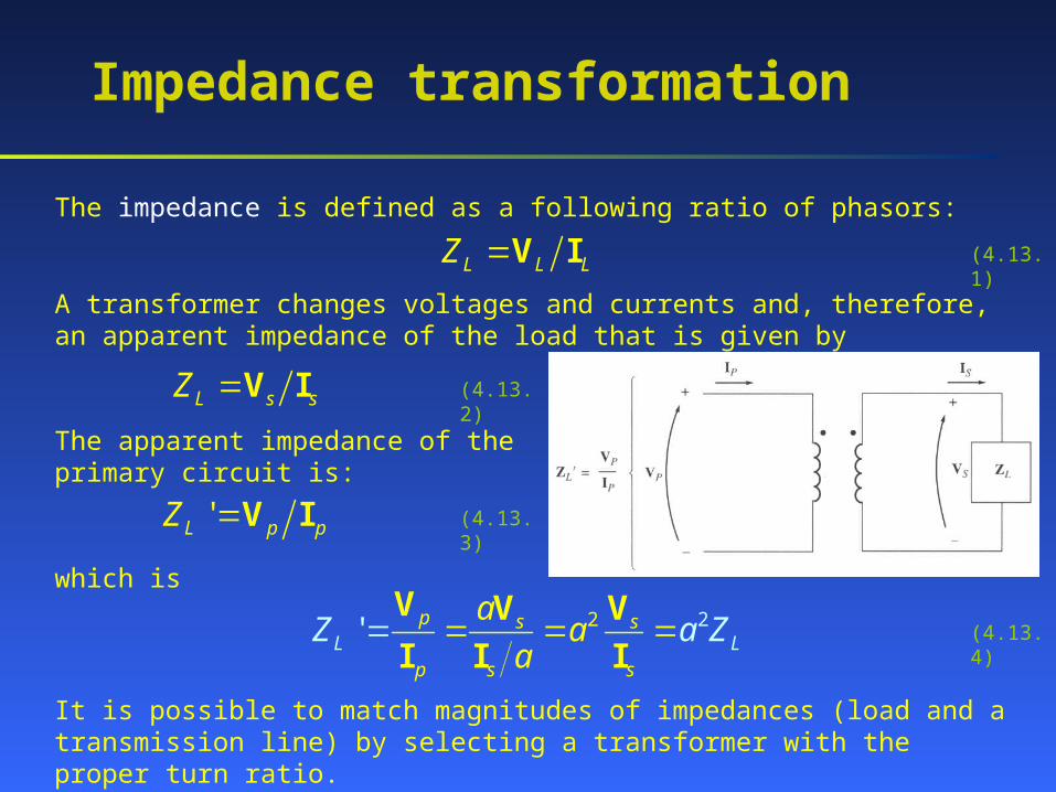
The impedance is defined as a following ratio of phasors:
L L LZ V I
A transformer changes voltages and currents and, therefore, an apparent impedance of the load that is given by
L s sZ V I
The apparent impedance of the primary circuit is:
'L p pZ V I
which is
2 2' p s s
p s sL L
aa
aZ a Z
V V V
I I I
It is possible to match magnitudes of impedances (load and a transmission line) by selecting a transformer with the proper turn ratio.
(4.13.1)
(4.13.2)
(4.13.3)
(4.13.4)
Theory of operation of real single-phase transformers
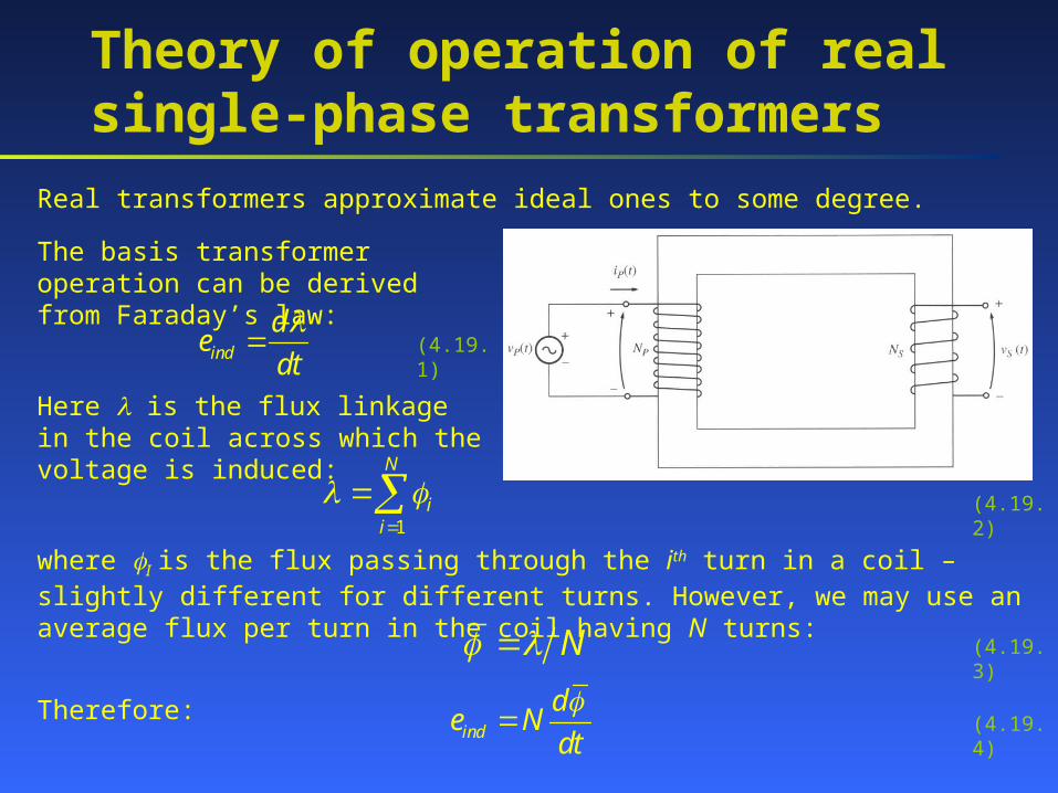
Real transformers approximate ideal ones to some degree.
The basis transformer operation can be derived from Faraday’s law:
ind
de
dt
(4.19.1)
Here is the flux linkage in the coil across which the voltage is induced:
1
N
ii
(4.19.2)
where I is the flux passing through the ith turn in a coil – slightly different for different turns. However, we may use an average flux per turn in the coil having N turns:
Therefore:
N
ind
de N
dt
(4.19.3)
(4.19.4)
The voltage ratio across a real transformer
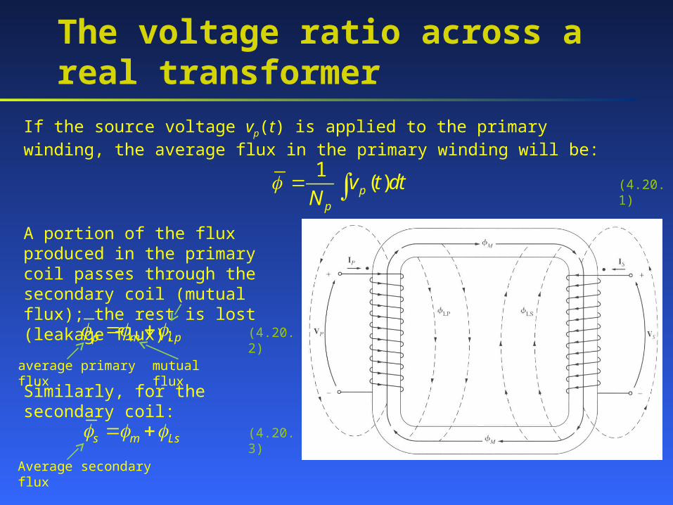
If the source voltage vp(t) is applied to the primary winding, the average flux in the primary winding will be:
1( )p
p
v t dtN
(4.20.1)
A portion of the flux produced in the primary coil passes through the secondary coil (mutual flux); the rest is lost (leakage flux):
p m Lp (4.20.2)
average primary flux mutual flux
Similarly, for the secondary coil:
s m Ls (4.20.3)
Average secondary flux
The voltage ratio across a real transformer
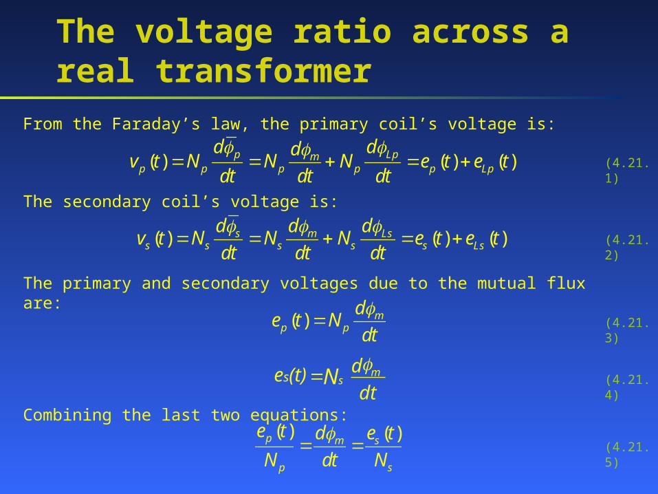
From the Faraday’s law, the primary coil’s voltage is:
( ) ( ) ( )p Lpmp p p p p Lp
d ddv t N N N e t e t
dt dt dt
The secondary coil’s voltage is:
( ) ( ) ( )s m Lss s s s s Ls
d d dv t N N N e t e t
dt dt dt
(4.21.1)
(4.21.2)
The primary and secondary voltages due to the mutual flux are:
( ) mp p
de t N
dt
(4.21.3)
(4.21.4)
Combining the last two equations:( ) ( )p m s
p s
e t d e t
N dt N
(4.21.5)
mNs des(t)dt
The voltage ratio across a real transformer
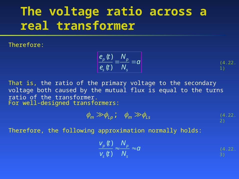
Therefore:
( )
( )p p
s s
e t Na
e t N (4.22.1)
That is, the ratio of the primary voltage to the secondary voltage both caused by the mutual flux is equal to the turns ratio of the transformer.
For well-designed transformers:
;m Lp m Ls
Therefore, the following approximation normally holds:
( )
( )p p
s s
v t Na
v t N
(4.22.2)
(4.22.3)
The magnetization current in a real transformer
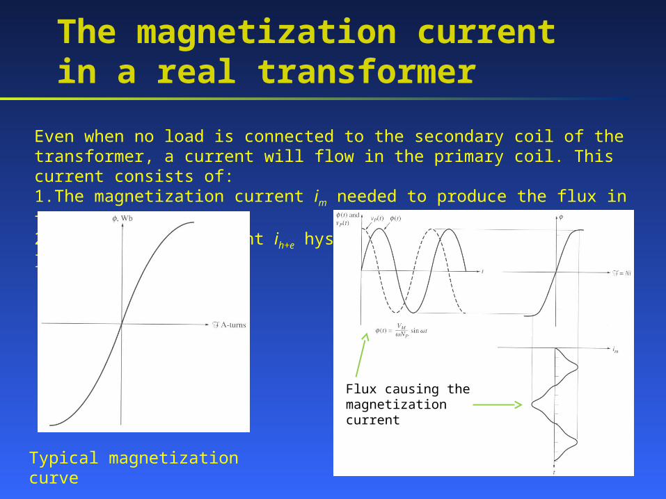
Even when no load is connected to the secondary coil of the transformer, a current will flow in the primary coil. This current consists of:1.The magnetization current im needed to produce the flux in the core;2.The core-loss current ih+e hysteresis and eddy current losses.
Flux causing the magnetization current
Typical magnetization curve
The magnetization current in a real transformer
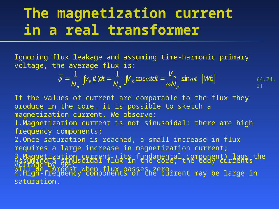
Ignoring flux leakage and assuming time-harmonic primary voltage, the average flux is:
1 1( ) cos sinmp m
p p p
Vv t dt V tdt t Wb
N N N
If the values of current are comparable to the flux they produce in the core, it is possible to sketch a magnetization current. We observe:1.Magnetization current is not sinusoidal: there are high frequency components;2.Once saturation is reached, a small increase in flux requires a large increase in magnetization current;3.Magnetization current (its fundamental component) lags the voltage by 90o;4.High-frequency components of the current may be large in saturation.
Assuming a sinusoidal flux in the core, the eddy currents will be largest when flux passes zero.
(4.24.1)
The magnetization current in a real transformer
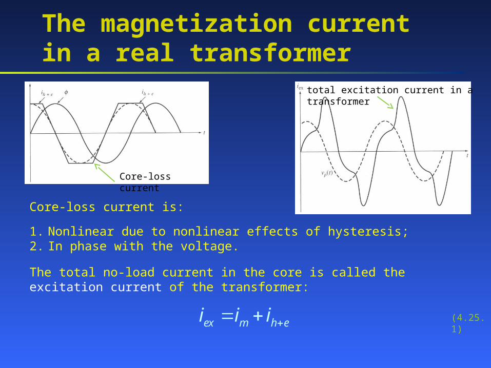
Core-loss current
Core-loss current is:
total excitation current in a transformer
1. Nonlinear due to nonlinear effects of hysteresis;2. In phase with the voltage.
The total no-load current in the core is called the excitation current of the transformer:
ex m h ei i i (4.25.1)
The current ratio on a transformer
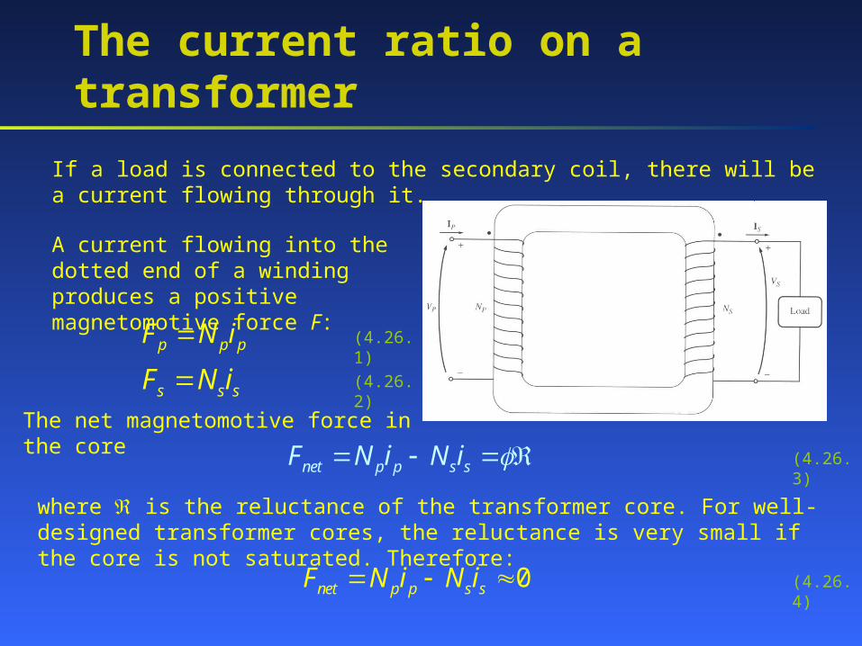
If a load is connected to the secondary coil, there will be a current flowing through it.
A current flowing into the dotted end of a winding produces a positive magnetomotive force F:
p p pF N i
s s sF N i
(4.26.1)
(4.26.2)
The net magnetomotive force in the core
net p p s sF N i N i
where is the reluctance of the transformer core. For well-designed transformer cores, the reluctance is very small if the core is not saturated. Therefore:
0net p p s sF N i N i
(4.26.3)
(4.26.4)
The current ratio on a transformer
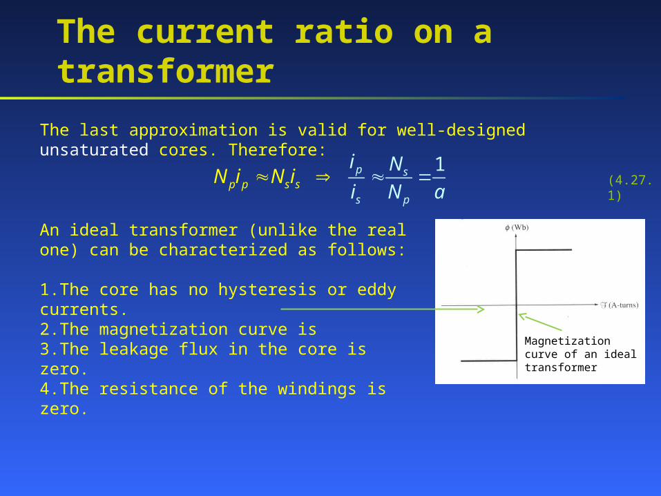
The last approximation is valid for well-designed unsaturated cores. Therefore:
1p
sp
sp s
ps
i N
i N aN i N i (4.27.1)
Magnetization curve of an ideal transformer
An ideal transformer (unlike the real one) can be characterized as follows:
1.The core has no hysteresis or eddy currents.2.The magnetization curve is3.The leakage flux in the core is zero.4.The resistance of the windings is zero.
The transformer’s equivalent circuit
To model a real transformer accurately, we need to account for the following losses:
1.Copper losses – resistive heating in the windings: I2R.2.Eddy current losses – resistive heating in the core: proportional to the square of voltage applied to the transformer.3.Hysteresis losses – energy needed to rearrange magnetic domains in the core: nonlinear function of the voltage applied to the transformer.4.Leakage flux – flux that escapes from the core and flux that passes through one winding only.
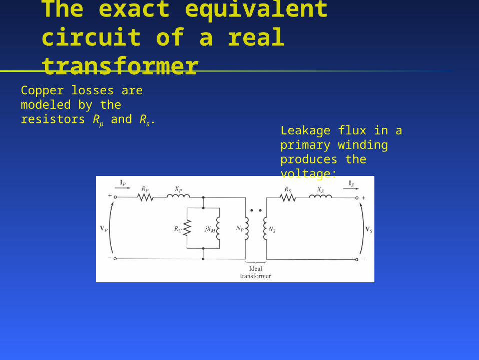
The exact equivalent circuit of a real transformer
Copper losses are modeled by the resistors Rp and Rs.
Leakage flux in a primary winding produces the voltage:
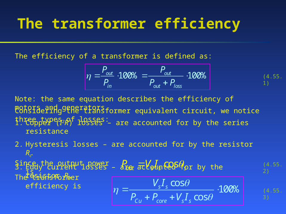
Considering the transformer equivalent circuit, we notice three types of losses:
The transformer efficiency
100% 100%out out
in out loss
P P
P P P
cosout s s sP V I
The efficiency of a transformer is defined as:
Note: the same equation describes the efficiency of motors and generators.
1. Copper (I2R) losses – are accounted for by the series resistance
2. Hysteresis losses – are accounted for by the resistor Rc.
3. Eddy current losses – are accounted for by the resistor Rc.
Since the output power is
The transformer efficiency iscos
100%cos
s s
Cu core s s
V I
P P V I
(4.55.1)
(4.55.2)
(4.55.3)
3-phase transformers
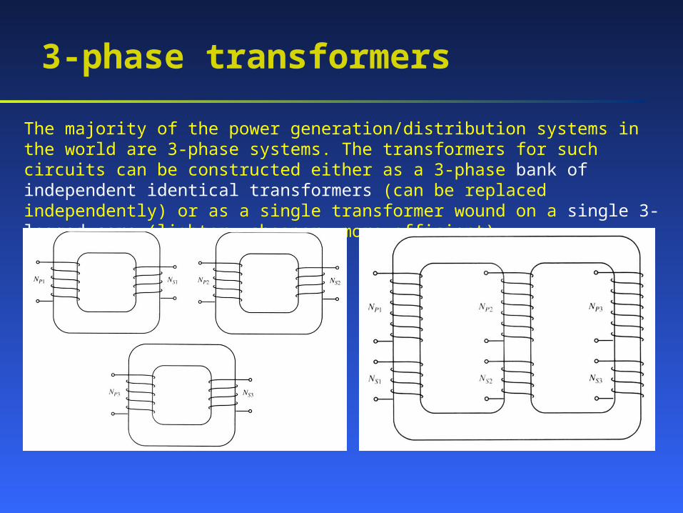
The majority of the power generation/distribution systems in the world are 3-phase systems. The transformers for such circuits can be constructed either as a 3-phase bank of independent identical transformers (can be replaced independently) or as a single transformer wound on a single 3-legged core (lighter, cheaper, more efficient).
3-phase transformer connections
We assume that any single transformer in a 3-phase transformer (bank) behaves exactly as a single-phase transformer. The impedance, voltage regulation, efficiency, and other calculations for 3-phase transformers are done on a per-phase basis, using the techniques studied previously for single-phase transformers.
Four possible connections for a 3-phase transformer bank are:
1. Y-Y2. Y-3. - 4. -Y
3-phase transformer connections
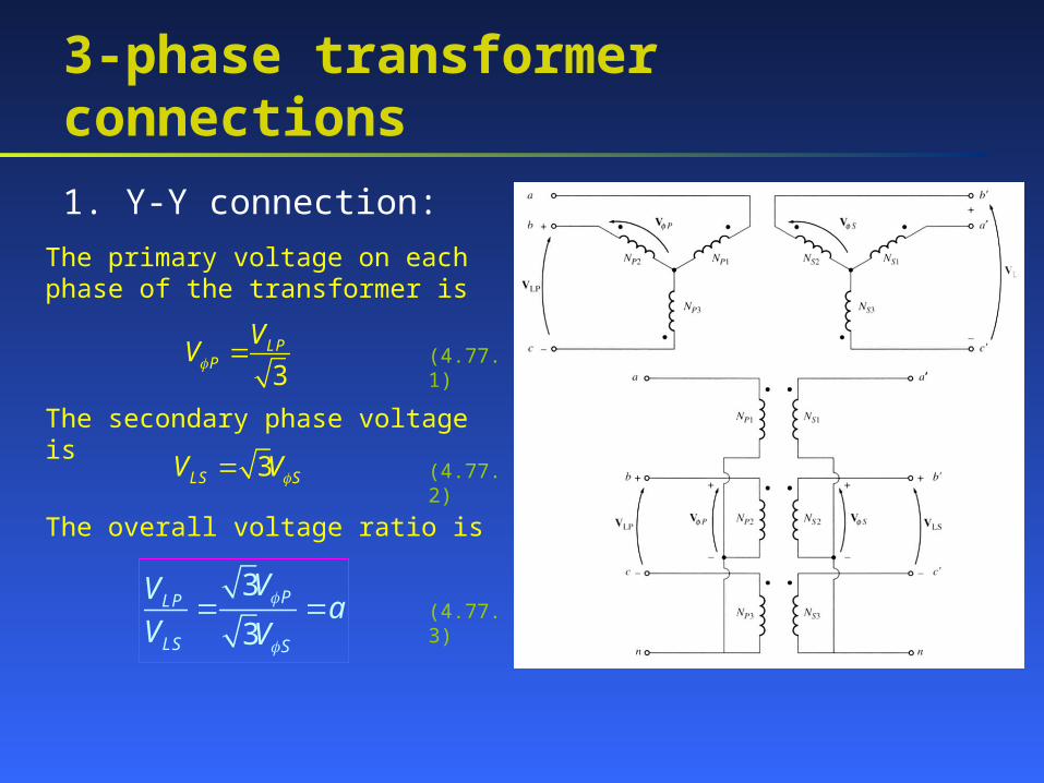
1. Y-Y connection:
The primary voltage on each phase of the transformer is
3LP
P
VV (4.77.1)
The secondary phase voltage is
3LS SV V (4.77.2)
The overall voltage ratio is
3
3PLP
LS S
VVa
V V
(4.77.3)
3-phase transformer connections
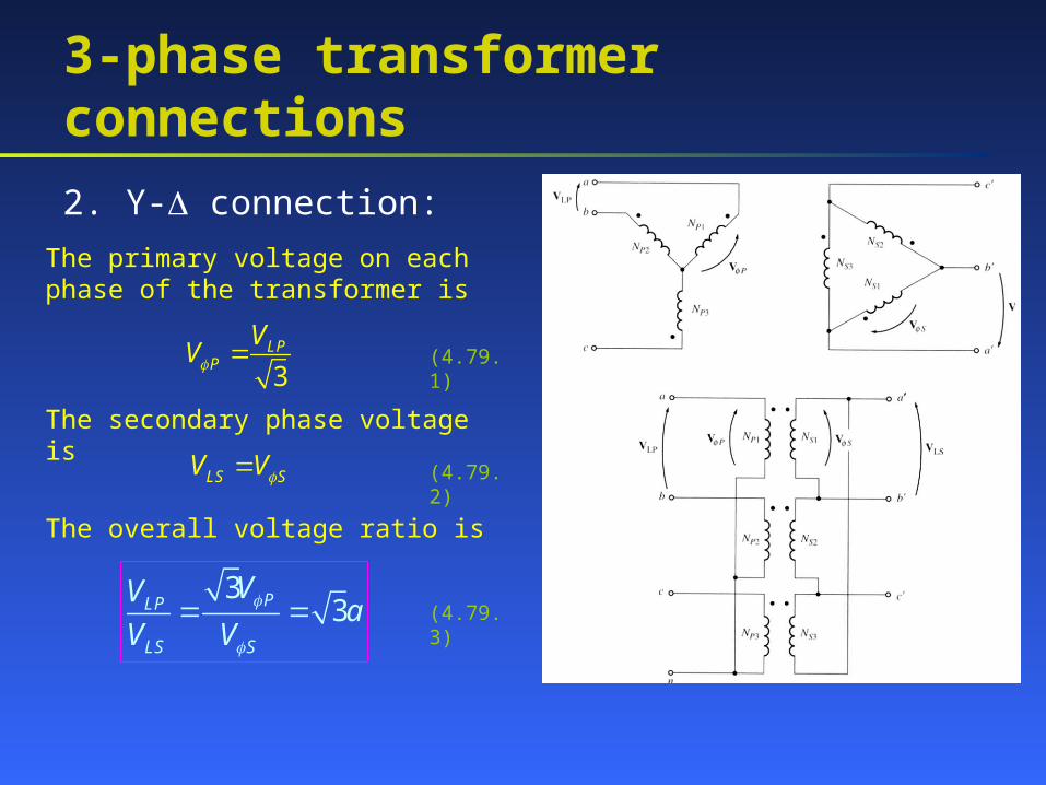
2. Y- connection:
The primary voltage on each phase of the transformer is
3LP
P
VV (4.79.1)
The secondary phase voltage is
LS SV V (4.79.2)
The overall voltage ratio is
33PLP
LS S
VVa
V V
(4.79.3)
3-phase transformer connections
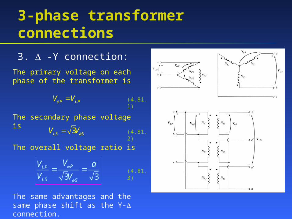
3. -Y connection:
The primary voltage on each phase of the transformer is
P LPV V (4.81.1)
The secondary phase voltage is
3LS SV V (4.81.2)
The overall voltage ratio is
3 3PLP
LS S
VV a
V V
(4.81.3)
The same advantages and the same phase shift as the Y- connection.
3-phase transformer connections
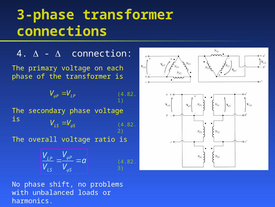
4. - connection:
The primary voltage on each phase of the transformer is
P LPV V (4.82.1)
The secondary phase voltage is
LS SV V (4.82.2)
The overall voltage ratio is
PLP
LS S
VVa
V V
(4.82.3)
No phase shift, no problems with unbalanced loads or harmonics.
Transformer ratings
Transformers have the following major ratings:
1. Apparent power;2. Voltage;3. Current;4. Frequency.
Transformer ratings: Voltage and Frequency
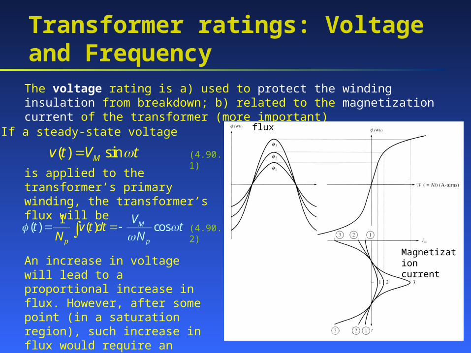
The voltage rating is a) used to protect the winding insulation from breakdown; b) related to the magnetization current of the transformer (more important)
If a steady-state voltage
( ) sinMv t V t (4.90.1)
is applied to the transformer’s primary winding, the transformer’s flux will be
( ) c) o1
s( M
p p
v t dV
t tN
tN
(4.90.2)
An increase in voltage will lead to a proportional increase in flux. However, after some point (in a saturation region), such increase in flux would require an unacceptable increase in magnetization current!
flux
Magnetization current
Transformer ratings: Voltage and Frequency
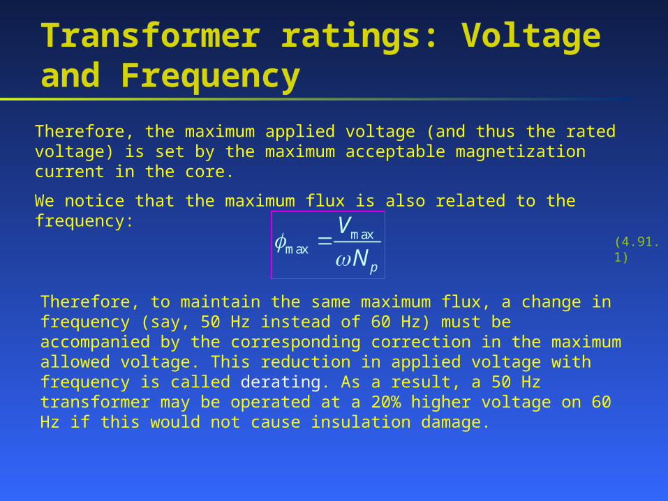
Therefore, the maximum applied voltage (and thus the rated voltage) is set by the maximum acceptable magnetization current in the core.
We notice that the maximum flux is also related to the frequency:
maxmax
p
V
N
(4.91.1)
Therefore, to maintain the same maximum flux, a change in frequency (say, 50 Hz instead of 60 Hz) must be accompanied by the corresponding correction in the maximum allowed voltage. This reduction in applied voltage with frequency is called derating. As a result, a 50 Hz transformer may be operated at a 20% higher voltage on 60 Hz if this would not cause insulation damage.
Transformer ratings: Apparent Power
The apparent power rating sets (together with the voltage rating) the current through the windings. The current determines the i2R losses and, therefore, the heating of the coils. Remember, overheating shortens the life of transformer’s insulation!
In addition to apparent power rating for the transformer itself, additional (higher) rating(s) may be specified if a forced cooling is used. Under any circumstances, the temperature of the windings must be limited.
Note, that if the transformer’s voltage is reduced (for instance, the transformer is working at a lower frequency), the apparent power rating must be reduced by an equal amount to maintain the constant current.